

Page 1
HAL SERIES
DLV 1280 Users Manual
Table of Contents
Section Contents Page
1
2
3
Introduction
Installation &
Setup
Operation
1.1 The Projector ....................................................................................................1-1
1.2 Components......................................................................................................1-2
1.3 Purchase Record and Servicing.........................................................................1-2
2.1 Quick Setup ......................................................................................................2-1
2.2 Installation Considerations................................................................................2-2
2.3 Projector Position and Mounting......................................................................2-8
2.4 Connecting Sources ........................................................................................2-11
2.5 Connecting to Power.......................................................................................2-15
2.6 Operating Orientation .....................................................................................2-16
2.7 Leveling..........................................................................................................2-16
2.8 Zoom, Focus & Offset ....................................................................................2-17
2.9 Connecting to the Serial Ports.........................................................................2-17
2.10 Keypad Protocols............................................................................................2-20
3.1 Overview...........................................................................................................3-1
3.2 Projector Basics................................................................................................3-1
3.3 Using the Keypads............................................................................................3-3
3.4 Navigating the Menus.....................................................................................3-10
3.5 Working With Sources and Channels .............................................................3-14
3.6 Adjusting the Image........................................................................................3-19
3.7 Adjusting and Checking System Parameters...................................................3-24
3.8 Using Multiple Projectors...............................................................................3-32
3.9 Error Conditions .............................................................................................3-33
4
5
6
54-007075-06P (12/98) Software Version 1.2
Maintenance
Specifications
Appendices
NOTE: Due to constant research, the information in this manual is subject to change without notice
4.1 Warnings and Guidelines..................................................................................4-1
4.2 Cleaning............................................................................................................4-3
4.3 Replacing Keypad Batteries..............................................................................4-3
4.4 Replacing the Lamp..........................................................................................4-4
4.5 Replacing the Filters.........................................................................................4-7
4.6 Changing the Lens ..........................................................................................4-10
4.7 Troubleshooting..............................................................................................4-11
5.1 Specifications....................................................................................................5-1
A Glossary...........................................................................................................A-1
B Keypad Reference ........................................................................................... B-1
C Menu Tree ........................................................................................................ C-1
D Serial Communication Cables..........................................................................D-1
E Optional Interface Modules ............................................................................. E-1
DLV 1280
User's Manual
iii
Page 2
Section 1
Introduction
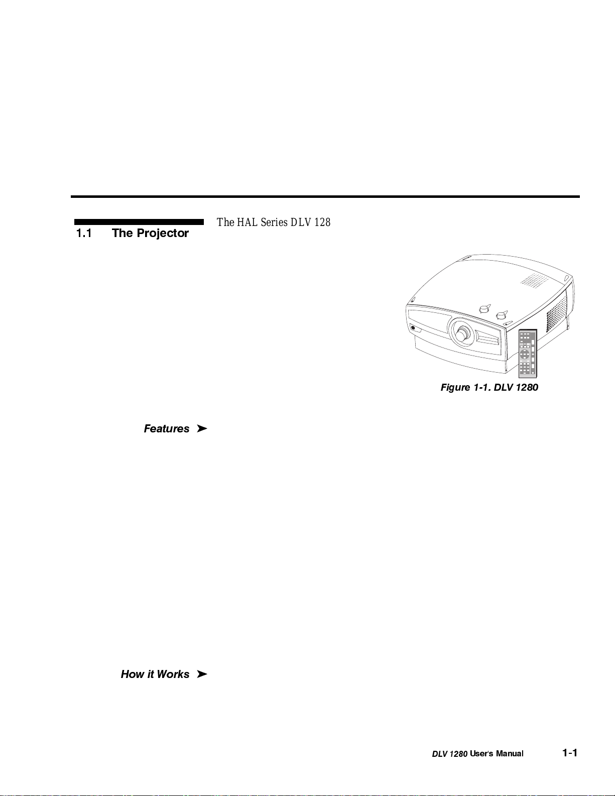
1.1 The Projector
Features
The HAL Series DLV 1280 is a professional quality projector that uses Digital
Light Valve (DLV) reflective technology from IBM
exceptional clarity and brilliance. The
high resolution, contrast and
consistency of DLV 1280 images is
ideal for situations in which superior
readability and detail are crucial, such
as control rooms, boardrooms, and
training venues. A complete
data/graphics/video projector, DLV
1280 can interface with IBM
compatible PCs, Macintosh and
computer workstations, and is
compatible with standard international
video formats. Main features are listed below:
'
◊ 1280 x 1024 pixels resolution
◊ 1000 lumens brightness
◊ Displays input from PCs, Macs, workstations, VCRs, laser-disc players,
video cameras, etc.
◊ NTSC, PAL and SECAM compatible
◊ Diagonal screen size up to 30 feet
◊ Set up and adjust images directly or through menus
◊ Memory for up to 99 different “channels” or source setups
◊ Active data loop-through capability for additional destinations
◊ RS-232 input with loop-through for networking multiple projectors
◊ Switcher and controller compatibility
◊ Input switching at projector or with remote keypad
◊ Long lamp life expectancy
◊ Power saving lamp modes for extended lamp life
◊ Interchangeable lenses
◊ Volume control for stereo PA system or (some models) internal speakers
◊ Modular design for ease of servicing
®
-
(some models require an opti onal decoder)
®
to project images with
Figure 1-1. DLV 1280
How it Works
DLV 1280 accepts data/graphics and video input signals for projection onto flat
'
or curved front or rear projection screens. High brightness light is generated by
an internal 500 watt CERMAX
transmitted by a system of optical components and sent to three DLV panels
responsible for either red, green or blue digitized video information. Light from
®
Xenon lamp. This light is collected and
DLV 1280
User's Manual
1-1
Page 3
INTRODUCTION
Construction
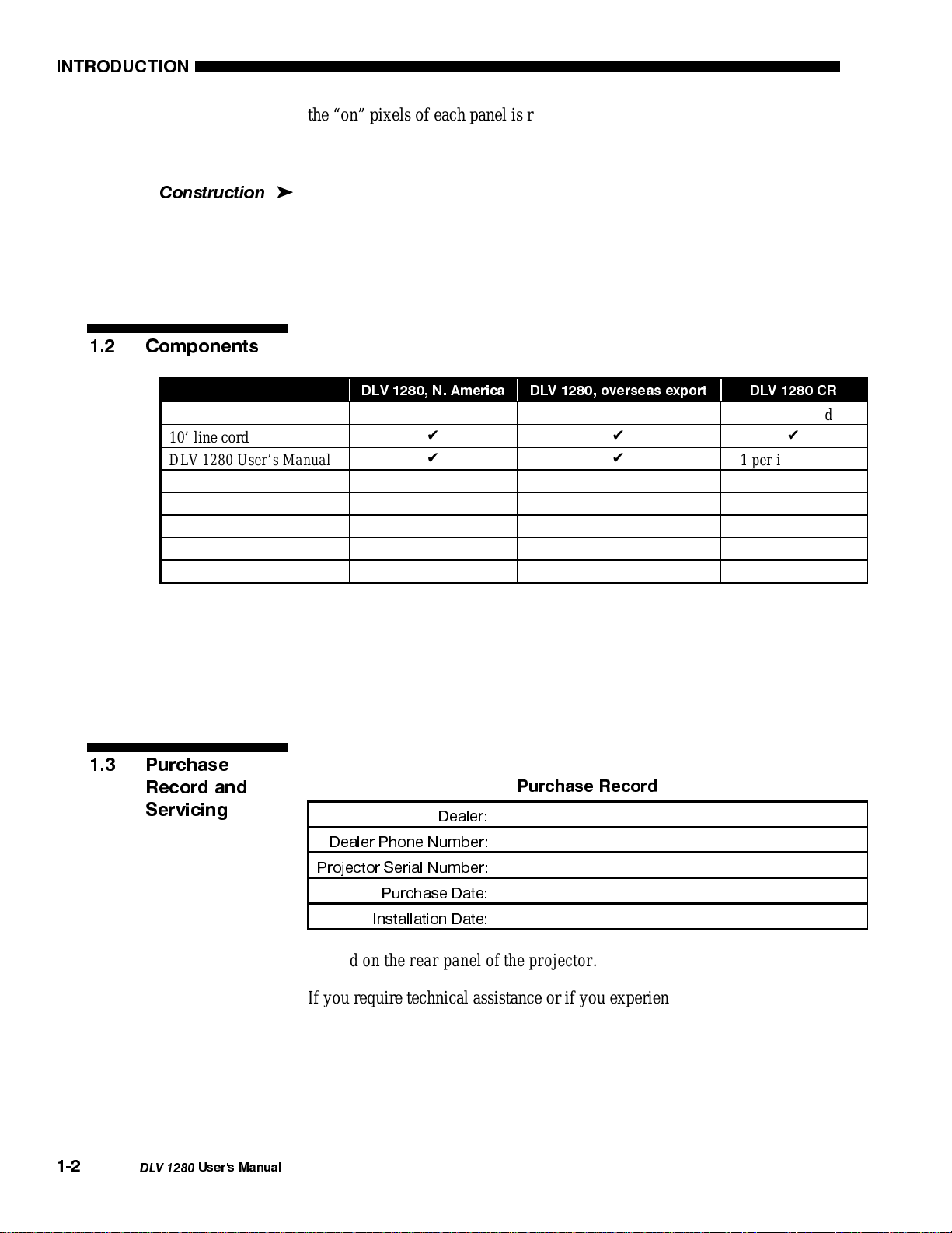
1.2 Components
Projector case covers
10’ line cord
DLV 1280 User’s Manual
Video functions
Audio functions
Internal speakers
IR remote keypad
Warranty card
the “on” pixels of each panel is reflected, converged and then projected to the
screen through a single front lens, where the pixels are all superimposed to
create a sharp full-color image.
The projector body is comprised of plastic panels and lid (DVL 1280 only), with
'
a durable powder-coated metal base. The top cover can be removed for quick
replacement of the lamp, filters or lens. A modular internal design ensures easeof-service and minimal down-time.
Make sure you have the items shown below. Fill out the warranty registration
card and mail it directly to Electrohome.
DLV 1280, N. America DLV 1280, overseas export DLV 1280 CR
✔✔
✔✔✔
✔✔
✔
✔
✔✔
✔✔
✔✔✔
not included not included
not included not included
not included
1 per installation
not included
1 per installation
1.3 Purchase
Record and
Servicing
NOTE: The overseas export DLV 1280 and the DLV 1280 CR do not include
video or audio functions. This manual assumes the video/audio options have
been installed.
Complete the information below for your records.
Purchase Record
Dealer:
Dealer Phone Number:
Projector Serial Number:
Purchase Date:
Installation Date:
NOTE: The projector serial number is on the projector's identification label
located on the rear panel of the projector.
If you require technical assistance or if you experience a problem with your
projector, contact the authorized Electrohome dealer from which the projector
was purchased. Whether the projector is under warranty or the warranty has
expired, Electrohome’s extensive factory and dealer service network is always
available. Electrohome service technicians are fully trained to quickly diagnose
and correct projector malfunction, often performing the service on site.
1-2
DLV 1280
User's Manual
Page 4
Section 2
Installation & Setup
This section explains how to install and set up the projector. If you are familiar with the projector and want to
quickly set it up for temporary use, follow the Quick Setup instructions. For a complete setup, follow the
instructions and guides covered in the remaining subsections.
NOTE: The overseas export DLV 1280 and the DLV 1280 CR do not include video or audio functions. This
manual assumes the video/audio options have been installed.
Follow these steps for quick setup of the projector:
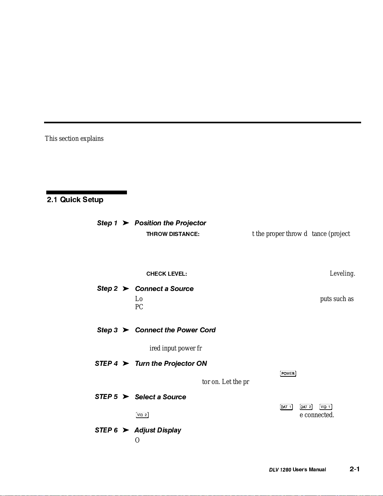
2.1 Quick Setup
Step1
Step2
Step3
STEP 4
STEP 5
'
Position the Projector
•
THROW DISTANCE:
to-screen distance) for your screen size and lens type. Make sure that the
projector front panel is parallel to the screen. See 2.3, Projector Position and
Mounting.
•
CHECK LEVEL:
'
Connect a Source
Locate the input panel at the rear of the projector. Connect RGB inputs such as
PCs to either Dat 1 or Dat 2. Connect video inputs such as VCRs to Vid 1
(composite) or Vid 2 (S-Video). See 2.4, Connecting a Source.
'
Connect the Power Cord
Plug the AC power cord into the AC power socket at the rear of the projector.
Required input power from 90 VAC to 264 VAC, 50 to 60 Hz is 9 amps.
'
Turn the Projector ON
Using either the built-in or IR remote keypad, press
or two to turn the projector on. Let the projector warm up for five minutes.
'
Select a Source
Using either the built-in or IR remote keypad, press
to select and display the image for the source you have connected.
Set the projector at the proper throw distance (projector-
Rotate the feet until the projector is level. See 2.7, Leveling.
and hold for a second
, , , or
STEP 6
'
Adjust Display
Once you have positioned the projector and are displaying a source image, adjust
as follows.
DLV 1280
User's Manual
2-1
Page 5
INSTALLATION & SETUP
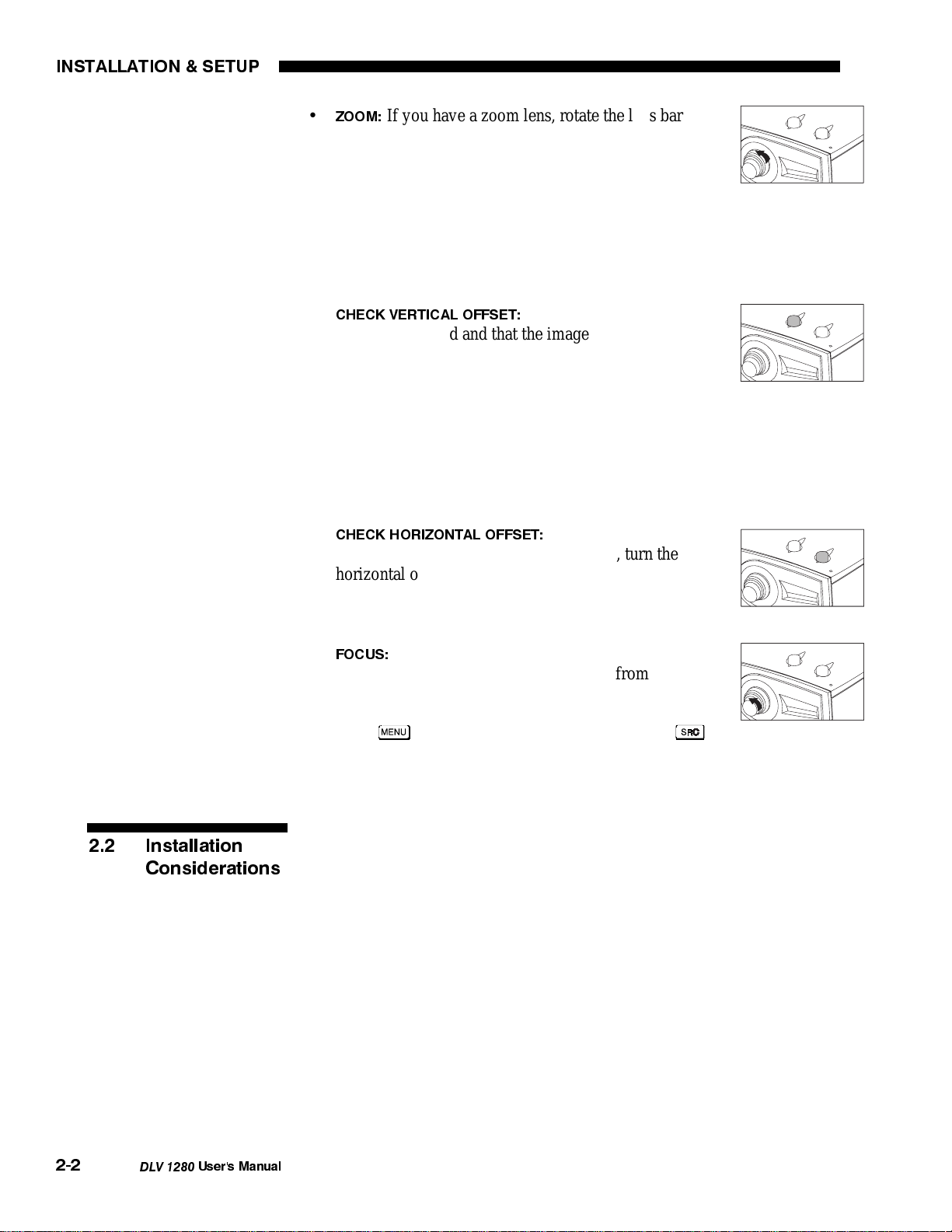
If you have a zoom lens, rotate the lens barrel
ZOOM:
•
end (closest to the projector) as desired to increase or
decrease the image size.
If you don’t have a zoom lens or if you can’t adjust the
image enough, the projector is likely not positioned at the proper throw
distance for your screen size. Power down, unplug the projector and move it
towards or away from the screen. See 2.3, Projector Position and Mounting
for details.
CHECK VERTICAL OFFSET:
•
To ensure that the image is
located as desired and that the image is a proper
rectangle rather than “keystoned” (having non-parallel
sides), turn the vertical offset knob located on the top of
the unit near the front edge—this is the knob closest to
the lens. Try to achieve the desired overall image position while obtaining a
rectangular image with the best overall brightness. If the image remains
keystoned, the projector may be too high or low for the screen. Also, ensure
that the projector is perpendicular to the screen. See 2.8, Zoom, Focus and
Offset and Figure 2-10.
CHECK HORIZONTAL OFFSET:
•
To mechanically place
your image slightly left or right of center, turn the
horizontal offset knob located on the top of the unit near
the front edge—this is the knob nearest the corner of the
projector. See Figure 2-9.
•
FOCUS:
When the image is the right size and shape,
rotate the lens barrel (at the end furthest from the
projector) until the image is as sharp as possible.
• Press
to refine other display settings, press
if
you want to select a different source or channel. See 3.5, Working With
Sources and Channels.
2.2 Installation
Considerations
2-2
DLV 1280
Although DLV 1280 delivers both high resolution and high brightness output,
your final display quality could be compromised if the projector is not properly
installed. This subsection discusses issues you should consider before
proceeding with a final installation. Even if you do not intend to use the
projector in a fixed and permanent installation, this subsection will help you to
better understand what may be done to ensure maximum performance.
User's Manual
Page 6
INSTALLATION & SETUP
yp
Installation T
e
Choose the installation type which suits your needs: front or rear screen, floor
'
mount or inverted mount.
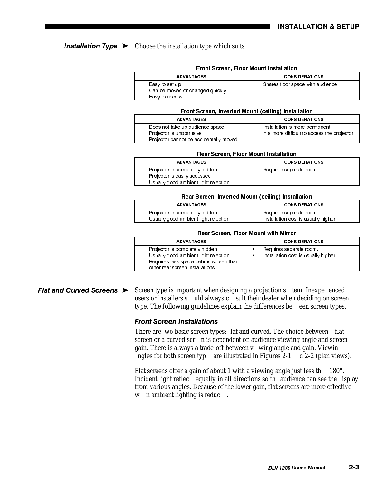
Front Screen, Floor Mount Installation
ADVANTAGES CONSIDERATIONS
•
Easy to set up
•
Can be moved or changed quickly
•
Easy to access
Front Screen, Inverted Mount (ceiling) Installation
ADVANTAGES CONSIDERATIONS
•
Does not take up audience space
•
Projector is unobtrusive
•
Projector cannot be accidentally moved
Rear Screen, Floor Mount Installation
ADVANTAGES CONSIDERATIONS
•
Projector is completely hidden
•
Projector is easily accessed
•
Usually good ambient light rejection
Rear Screen, Inverted Mount (ceiling) Installation
ADVANTAGES CONSIDERATIONS
•
Projector is completely hidden
•
Usually good ambient light rejection
•
Shares floor space with audience
•
Installation is more permanent
•
It is more difficult to access the projector
•
Requires separate room
•
Requires separate room
•
Installation cost is usually higher
Flat and Curved Screens
Rear Screen, Floor Mount with Mirror
ADVANTAGES CONSIDERATIONS
•
Projector is completely hidden
•
Usually good ambient light rejection
•
Requires less space behind screen than
other rear screen installations
Screen type is important when designing a projection system. Inexperienced
'
•
Requires separate room.
•
Installation cost is usually higher
users or installers should always consult their dealer when deciding on screen
type. The following guidelines explain the differences between screen types.
Front Screen Installations
There are two basic screen types: flat and curved. The choice between a flat
screen or a curved screen is dependent on audience viewing angle and screen
gain. There is always a trade-off between viewing angle and gain. Viewing
angles for both screen types are illustrated in Figures 2-1 and 2-2 (plan views).
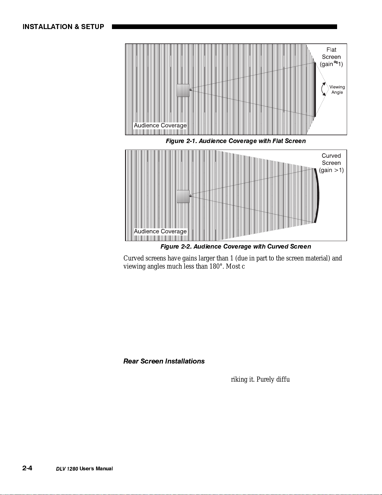
Flat screens offer a gain of about 1 with a viewing angle just less than 180°.
Incident light reflects equally in all directions so the audience can see the display
from various angles. Because of the lower gain, flat screens are more effective
when ambient lighting is reduced.
DLV 1280
User's Manual
2-3
Page 7
INSTALLATION & SETUP
Figure 2-1. Audience Coverage with Flat Screen
Figure 2-2. Audience Coverage with Curved Screen
Curved screens have gains larger than 1 (due in part to the screen material) and
viewing angles much less than 180°. Most curved screens have different
horizontal and vertical viewing angles. Incident light does not reflect equally in
all directions. The reflected light concentrates in a conical volume or "viewing
cone". Audiences within the viewing cone see a brighter image than that from an
equal area on a flat screen. Audiences outside the viewing cone see a dimmer
image.
NOTE: While DLV 1280 lenses are designed primarily for use with flat screens,
the depth-of-field range for these lenses allows focusing on curved screens as
well. Focus remains sharp, however there may be significant pincushion
distortion, primarily at the top of the screen..
Rear Screen Installations
There are two basic types of rear screens: diffused and optical. A diffused screen
has a surface which spreads the light striking it. Purely diffused screens have a
gain of less than 1. The main advantage of the diffused screen is its wide viewing
angle, similar to that of a flat screen for front screen projection. Optical screens
take light from the projector and redirect it to increase the light intensity at the
front of the screen. This reduces it in other areas. A viewing cone, similar to that
of a curved front screen installation, is created.
2-4
DLV 1280
To summarize, optical screens are better suited for brightly lit rooms where the
audience is situated within the viewing cone. Diffused screens are best suited
when a wide viewing angle is required but there is low ambient room lighting.
User's Manual
Page 8
Screen Size
INSTALLATION & SETUP
Choose a screen size which is most appropriate for your lens and application.
'
Table 2-1. Screen Size Ranges
Lens Type Diagonal Screen Size* (if 5:4)
2:1 - 3:1 zoom 2.3 - 30 (0.7 - 9 meters)
1.2:1 fixed 4 - 10 (1.2 - 3.1 meters)
1.5:1 - 3:1 zoom 4 - 30 (1.2 - 9 meters)
3:1 - 7:1 zoom 6 - 30 (1.8 - 9 meters)
Note: Stated screen sizes refer to the diagonal size of a 5:4 screen.
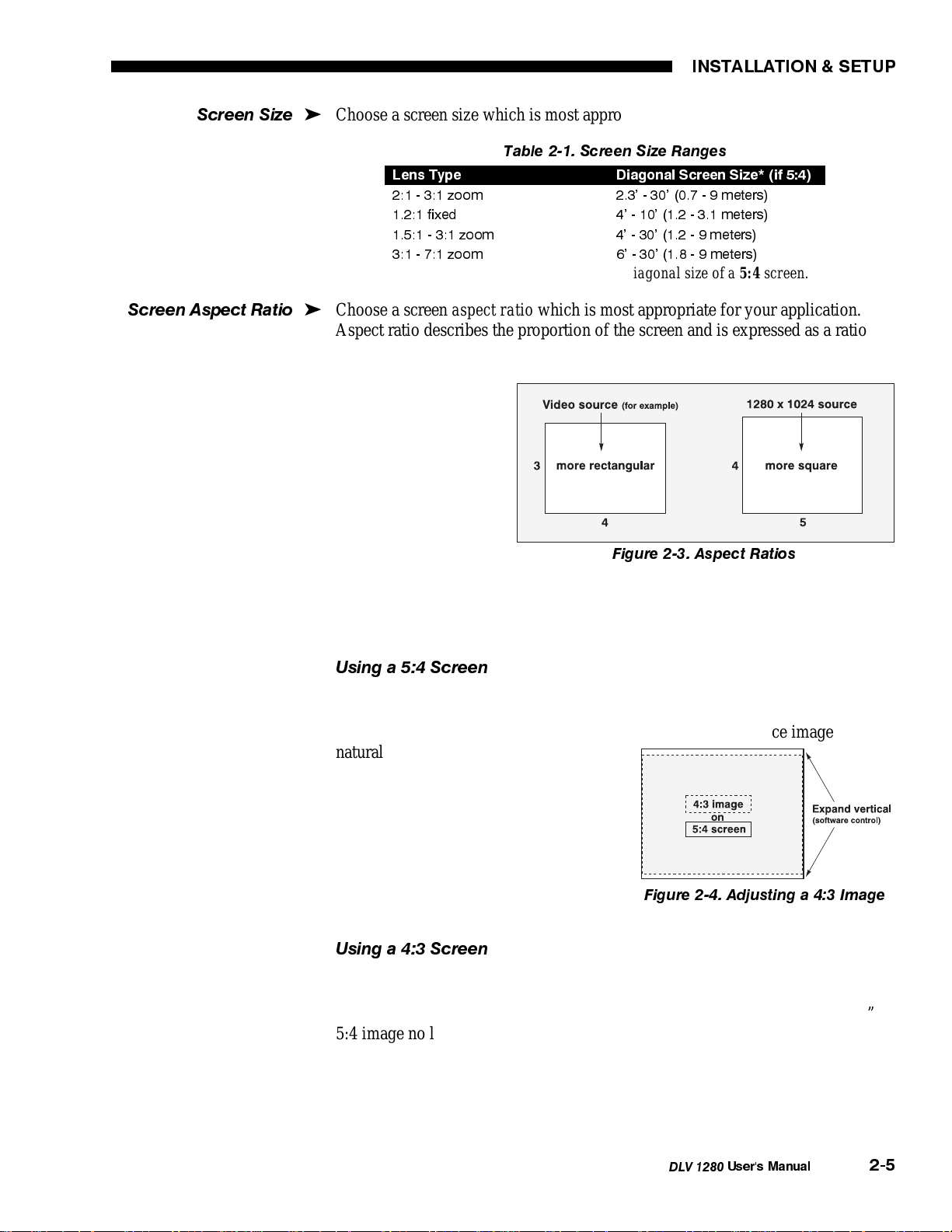
Screen Aspect Ratio
Choose a screen
'
aspect ratio
which is most appropriate for your application.
Aspect ratio describes the proportion of the screen and is expressed as a ratio of
width to height, such as “4:3” or “5:4”. Ideally, to exactly fill a screen with an
image, the aspect ratio of the screen should correspond to the aspect ratio of the
image, which depends
on the source in use.
For example, standard
video from a VCR has
a 4:3 aspect ratio,
whereas a high
resolution SXGA
signal (1280 x 1024)
has a 5:4 aspect ratio.
Figure 2-3. Aspect Ratios
See Figure 2-3.
NOTE: With a few exceptions, sources with
than 1280 x 1024 resolution
less
have a 4:3 aspect ratio. The correct aspect ratio for 1280 x 1024 sources is 5:4.
Using a 5:4 Screen
If you use a mix of sources—i.e., those with the rectangular 4:3 aspect ratio as
well as those with the slightly more square 5:4 aspect ratio—a 5:4 screen will
likely provide the most flexibility. With a 5:4 screen, a 5:4 source image
naturally fills the screen at an established
throw distance. Filling the same screen
with a 4:3 source image requires only a
simple software adjustment to slightly
expand the image to the top and bottom
edges of the screen (Figure 2-4). See 3.6,
Adjusting the Image.
Figure 2-4. Adjusting a 4:3 Image
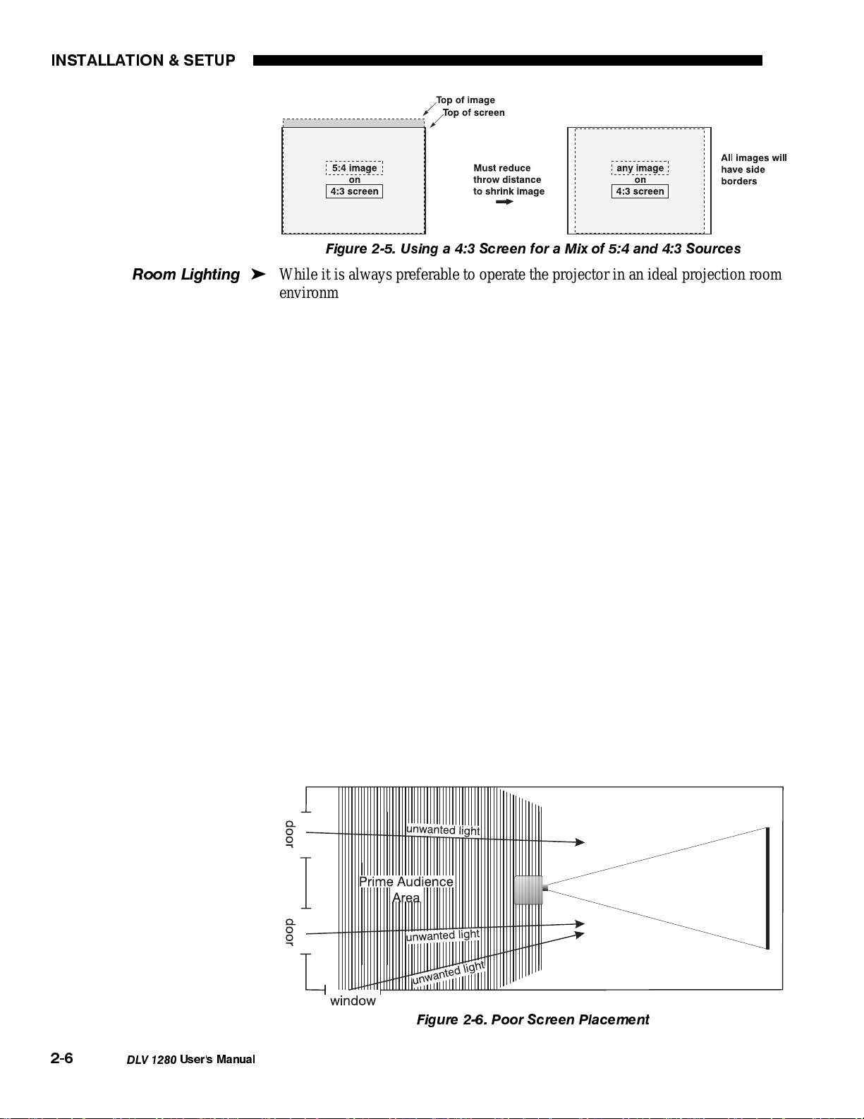
Using a 4:3 Screen
With a 4:3 screen, 4:3 sources will naturally fill the screen at an established
throw distance. Filling the same screen with a 5:4 source image (one from a 1280
x 1024 source) requires a reduction in this throw distance so that the “too tall”
5:4 image no longer spills over the top or bottom of the screen. Once set up in
this manner, all images will then have side borders (Figure 2-5), with most 4:3
images changing aspect ratio as well.
NOTE: For existing installations having multiple 4:3 screens, you can use
Electrohome’s EX-1200 or EX-2000 Display Wall controller to fill each screen.
DLV 1280
User's Manual
2-5
Page 9
INSTALLATION & SETUP
g
Figure 2-5. Using a 4:3 Screen for a Mix of 5:4 and 4:3 Sources
Room Lightin
While it is always preferable to operate the projector in an ideal projection room
'
environment, the high brightness output of DLV 1280 is well suited for locations
where ambient lighting may be less than optimum for projection. For temporary
installations where the room may not be designed for projection, there are many
simple things which can be done to avoid problems caused by unwanted light.
Visiting a movie theater can give you an idea of what makes a good projection
environment. Walls, floors and furnishings are dark and matte finished. A
projection room should not have reflective white ceilings or non-directional
lighting such as fluorescent lights. The white ceiling spreads light, making the
room appear brighter. Keep lighting and reflections to a minimum.
If it is not possible to eliminate fluorescent lights, consider using parabolic
reflectors ("egg crates") to direct light down to the floor. Incandescent spot
lighting is a better way to obtain illumination. Light dimmers or rheostats allow
you to further control the lighting.
Outside windows are undesirable in any projection room. A small crack between
curtains on a sunny day can wash out a projected image. If you do have
windows, make sure that window coverings are opaque and overlapping — some
window coverings are designed to provide up to 100 percent blockage of outside
light. Ideally, the material should have a matte finish.
2-6
DLV 1280
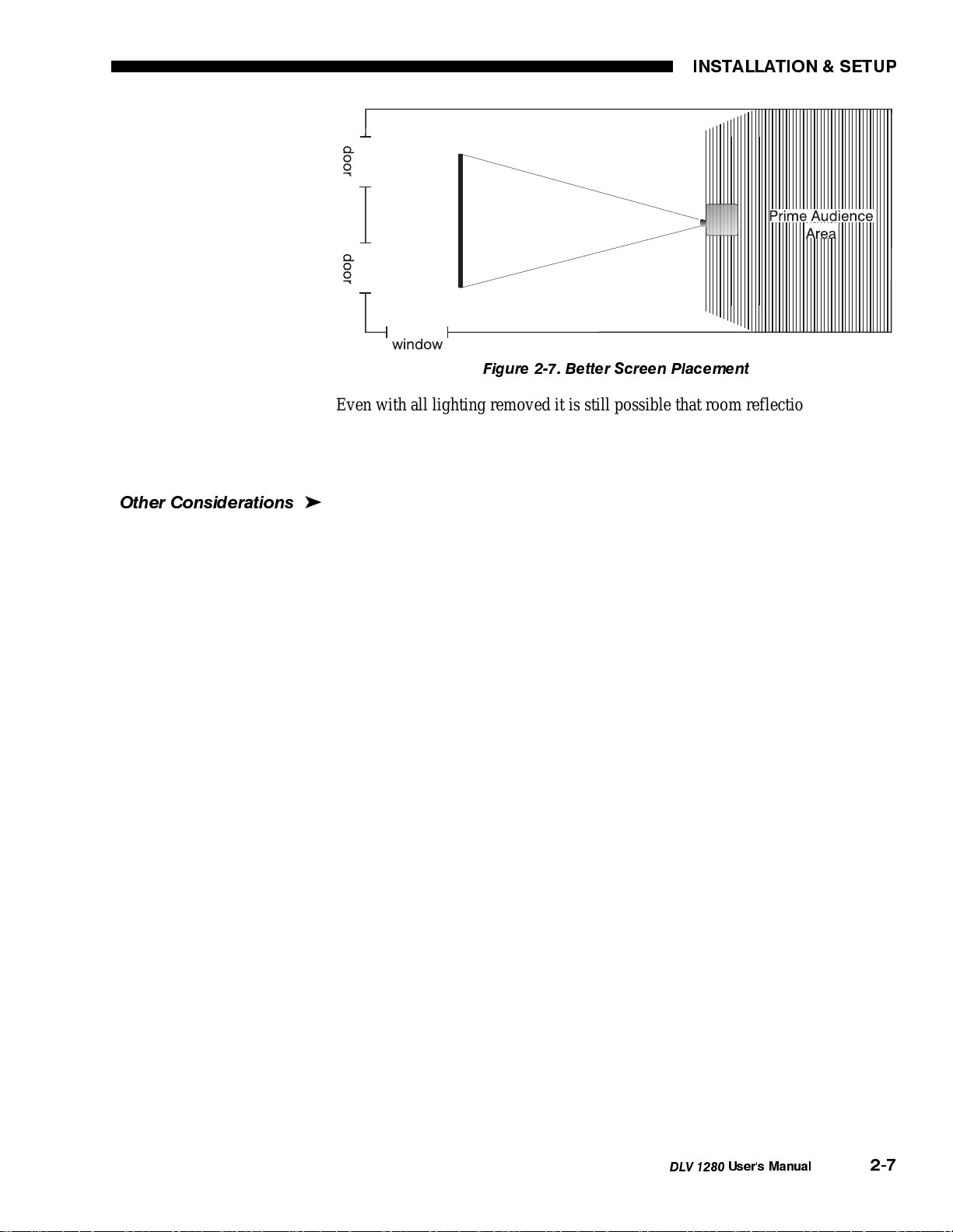
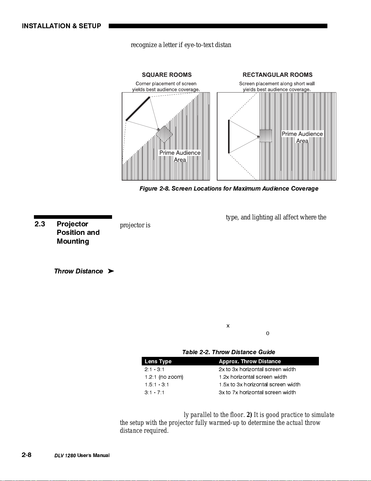
To minimize the effects caused by unwanted light from door and aisle ways,
carefully choose the position of your projector and screen. Figure 2-6 shows an
installation where poor screen placement allows too much unwanted light to
enter the screen. In Figure 2-7, the screen and the projector are positioned to
minimize the effect of unwanted light.
Figure 2-6. Poor Screen Placement
User's Manual
Page 10
Other Considerations
INSTALLATION & SETUP
Figure 2-7. Better Screen Placement
Even with all lighting removed it is still possible that room reflections within the
room can degrade the image. Light from the projection screen should be
absorbed by the ceilings, walls and floors so that it will not be reflected back to
the screen. Again, reflective surfaces should be kept to a minimum.
Here are some other considerations and tips which can help you improve your
'
installation:
• Ventilation is an important factor when preparing a projection room. The
ambient temperature should be kept constant and below 35°C (95°F). Keep
the projector away from heating and/or air conditioning vents. Changes in
temperature can cause drifts in the projector circuitry which may affect
performance.
• Keep the projector away from devices which radiate electromagnetic energy
such as motors and transformers. Common sources of these are slide
projectors, speakers, power amplifiers, elevators, etc.
• For rear screen applications, less space is required if a mirror is used to fold
the optical path.
• Choose the right screen size for the application:
◊ As screen size increases, magnification increases which reduces
brightness. Select a screen size which is appropriate for the venue,
but not larger than that required.
◊ Installing a large screen in a small room is similar to watching
television close up; too large a screen can overpower a room. A good
rule of thumb is to be no closer than 1.5 times the width of the
screen.
◊ Larger screens require greater attention to lighting conditions.
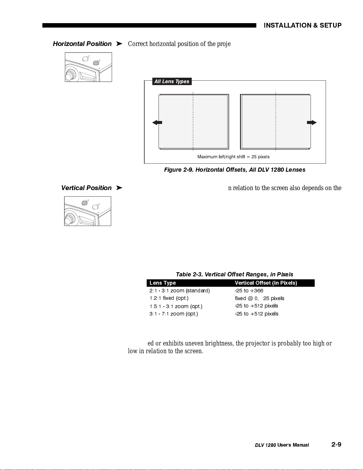
• When laying out the projection room, consider positioning the projector and
screen in a manner which will achieve maximum audience coverage and
space efficiency. For example, placing the screen along the larger wall in a
rectangular room will reduce audience coverage. Figure 2-8 shows two
examples of how audience coverage is maximized.
• Keep in mind that for good display of text information, the image size must
allow the audience to distinguish all text clearly. In general, the eye can
DLV 1280
User's Manual
2-7
Page 11
INSTALLATION & SETUP
recognize a letter if eye-to-text distance is less than 150 times the height of
the letter. Text will normally become illegible at a greater distance despite
the sharpest and clearest of images.
Figure 2-8. Screen Locations for Maximum Audience Coverage
2.3 Projector
Position and
Mounting
Throw Distance
As mentioned, installation type, screen type, and lighting all affect where the
projector is positioned. In addition, both throw distance (the distance between
the projector and screen) and horizontal/vertical position must be determined for
every new installation. Both depend on screen size and projector lens type. Make
sure that the room can accommodate the required position of the projector for the
chosen screen size.
Throw distance is the distance between the projector's front feet and the screen
'
(measured perpendicular to the screen and projector, not necessarily parallel to
floor). As the distance between the projector and the screen increases, image size
also increases.
Throw distance is roughly equal to the horizontal width of the screen multiplied
by the type of lens you are using. For example, if using a 1.2:1 lens, throw
the horizontal screen width. Once you
distance should be roughly equal to 1.2
x
know your horizontal screen size, you can determine how far away the projector
should be:
Table 2-2. Throw Distance Guide
Lens Type Approx. Throw Distance
2:1 - 3:1 2x to 3x horizontal screen width
1.2:1 (no zoom) 1.2x horizontal screen width
1.5:1 - 3:1 1.5x to 3x horizontal screen width
3:1 - 7:1 3x to 7x horizontal screen width
2-8
DLV 1280
NOTES: 1) Throw distance is measured perpendicular to the screen and
projector, not necessarily parallel to the floor. 2) It is good practice to simulate
the setup with the projector fully warmed-up to determine the actual throw
distance required.
User's Manual
Page 12
INSTALLATION & SETUP
Horizontal Position
Vertical Position
Correct horizontal position of the projector can ensure that the image is
'
positioned properly on the screen. With any lens installed, the image can be
manually offset left or right by a distance of up to 25 pixels (Figure 2-9). Turn
the horizontal offset adjustment knob on the top edge of the projector as desired.
Figure 2-9. Horizontal Offsets, All DLV 1280 Lenses
The vertical position of the projector in relation to the screen also depends on the
'
size of the screen and the lens type. Correct vertical position ensures that the
image will be rectangular in shape rather than keystoned (having non-parallel
sides). Depending on the type of lens you are using, the image can also be offset
up or down by turning the vertical offset adjustment knob on the top edge of the
projector.
The number of pixels by which you can raise or lower an image are listed in
Table 2-3. In addition, refer to Figure 2-10 to see how these pixel offsets affect
the placement of your image. If your projector is inverted, such as with a ceiling
-mounted projector, turn the illustration upside-down.
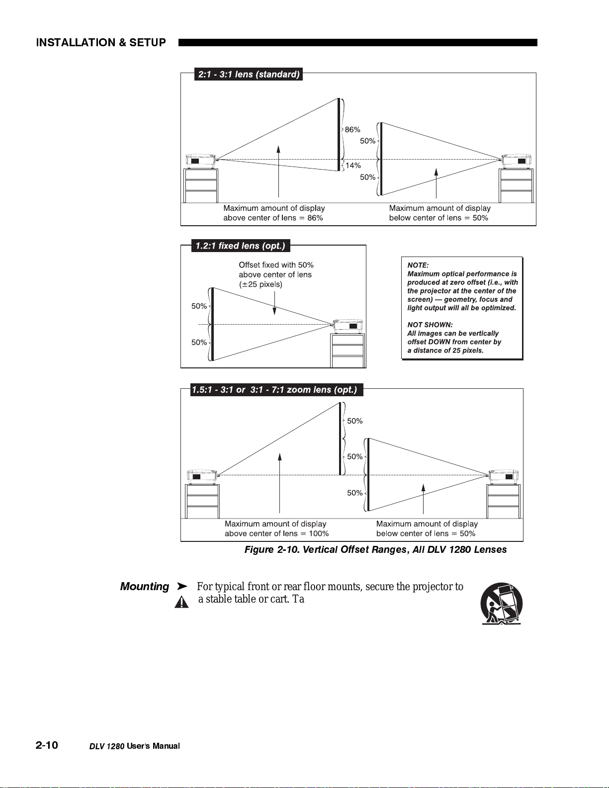
Table 2-3. Vertical Offset Ranges, in Pixels
Lens Type Vertical Offset (in Pixels)
2:1 - 3:1 zoom (standard) -25 to +366
1.2:1 fixed (opt.)
1.5:1 - 3:1 zoom (opt.)
3:1 - 7:1 zoom (opt.) -25 to +512 pixels
fixed @ 0,±25 pixels
-25 to +512 pixels
NOTE: If you cannot raise or lower the image enough, or if the image becomes
keystoned or exhibits uneven brightness, the projector is probably too high or
low in relation to the screen.
DLV 1280
User's Manual
2-9
Page 13
INSTALLATION & SETUP
g
2-10
DLV 1280
Mountin
User's Manual
Figure 2-10. Vertical Offset Ranges, All DLV 1280 Lenses
For typical front or rear floor mounts, secure the projector to
'
a stable table or cart. Take particular care with a mobile
cart—avoid sudden stops, excessive force and uneven surfaces
th at may c a u s e t h e p r o j e c t o r a n d c a r t c o m b i n a t i o n t o overturn.
The table or cart should be reasonably level, but fine adjustments to the projector
level can be made by adjusting the height of the projector legs; refer to 2.7,
Leveling for details.
To invert the projector you must use a proper ceiling mount fixture. For more
information, contact Electrohome.
Page 14
INSTALLATION & SETUP
p
Folded O
2.4 Connecting
Sources
tics
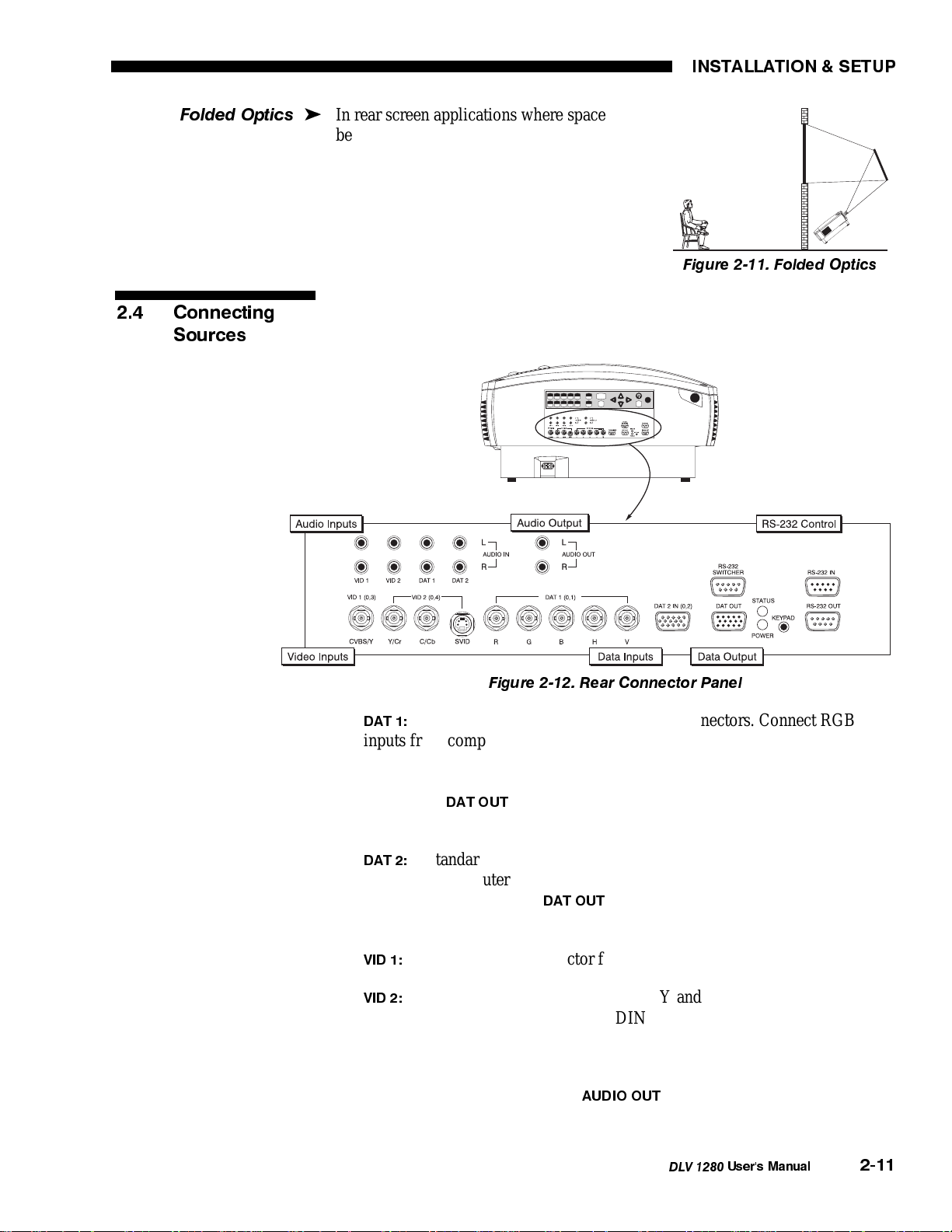
In rear screen applications where space
'
behind the projector is limited, a mirror may
be used to fold the optical path. See Figure 2-
11. The position of the projector and mirror
must be accurately set. If considering this type
of installation, call your dealer for assistance.
Figure 2-11. Folded Optics
At the rear of the projector is a standard input panel to which you may connect a
variety of source types (Figure 2-12). NOTE: Audio/video not standard for all
models. The illustration below shows all options installed.
Figure 2-12. Rear Connector Panel
A standard RGB input with five BNC connectors. Connect RGB
DAT 1:
•
inputs from computer sources such as VGA, SVGA, Mac, PowerMac, DEC,
Sun, SGI and others. DLV 1280 supports multiple sync types: sync-on-green
for data, composite, and separate H & V. If desired, loop the signal out
through the
DAT OUT
port to a second destination, such as a monitor or
another projector.
•
A standard RGB input with a VGA input (15-pin) connector. Connect
DAT 2:
compatible computer analog signals to the “Dat 2” port and, if desired, loop
the signal out through the
DAT OUT
port to a second display, such as monitor
or another projector.
•
•
A standard BNC connector for composite video sources.
VID 1:
A pair of standard BNC connectors (Y and C, for luminance and
VID 2:
chrominance) or a single 4-pin mini DIN connector for S-Video sources.
To control audio levels, connect pre-amplified (line level) audio inputs to the left
and right audio inputs corresponding to the input labeling (Dat 1, Dat 2, Vid 1,
or Vid 2). Then, if desired, connect
AUDIO OUT
to external audio amplification
equipment. Use RCA-type cables and connectors for all audio.
DLV 1280
User's Manual
2-11
Page 15
INSTALLATION & SETUP
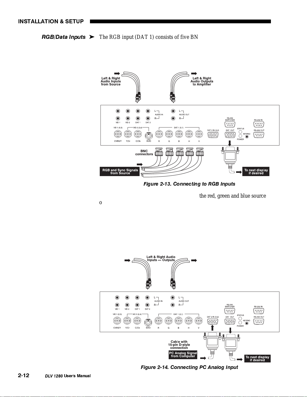
RGB/Data Inputs
The RGB input (DAT 1) consists of five BNC type connectors for connection to
'
a variety of RGB sources. Such sources include VGA, SVGA, SXGA, XGA,
Mac, PowerMac, DEC, Sun, SGI and others. DLV 1280 supports multiple sync
types: sync-on-green for data, composite, and separate H & V (3-,4-, or 5-wire
RGB).
Figure 2-13. Connecting to RGB Inputs
Connect the sync BNC inputs. Then connect the red, green and blue source
outputs to the RED, GREEN, and BLUE inputs on the panel. If the source uses
sync-on-green, you only need to connect the red, green, and blue. If your source
provides a composite sync output, connect it to the H input. If your source
provides separate horizontal and vertical sync outputs, connect horiz ontal sync to the H
input and connect vertical sync to the V input. See Figure 2-13.
Connect PC analog sources to Dat 2 as shown in Figure 2-14. You may need an
adapter if you are connecting a Mac to Dat 2.
2-12
DLV 1280
Figure 2-14. Connecting PC Analog Input
User's Manual
Page 16
INSTALLATION & SETUP
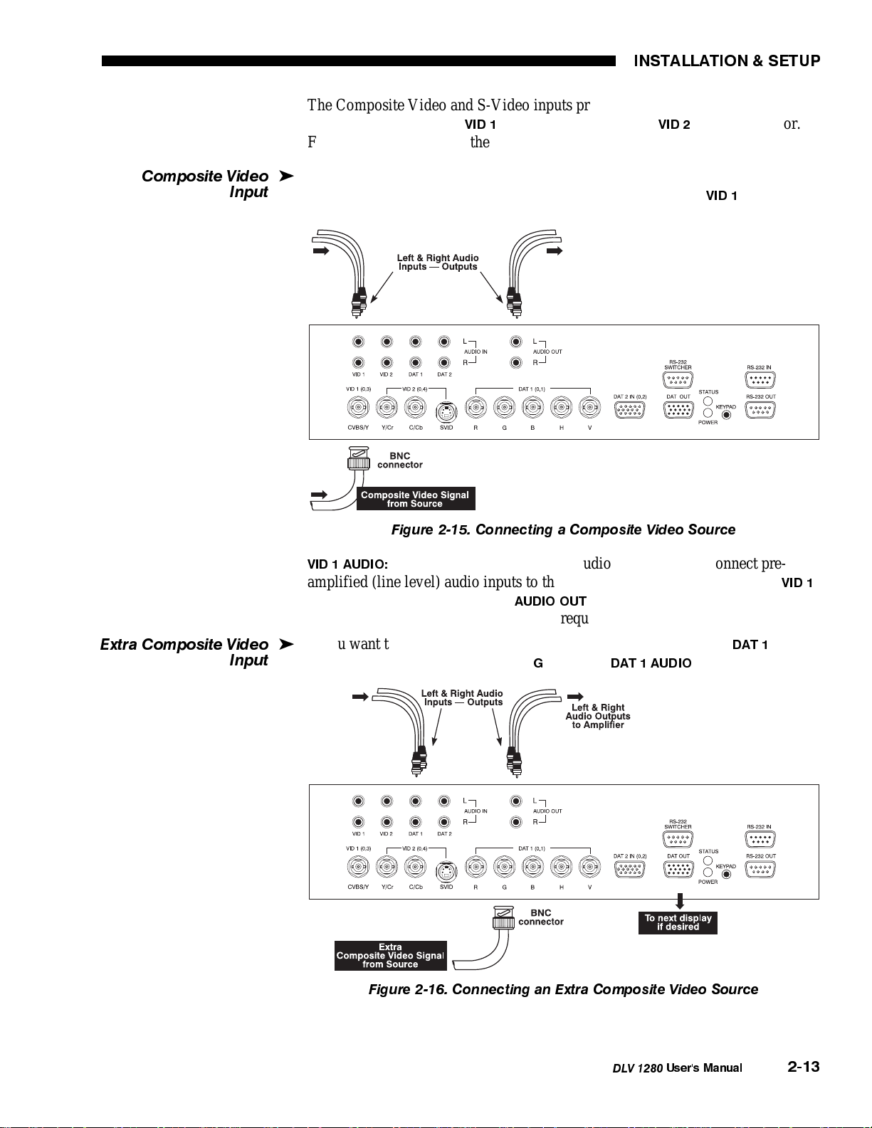
The Composite Video and S-Video inputs provide simultaneous connection of a
composite video source (
) and an S-Video source (
VID 1
) to the projector.
VID 2
For each video input, use the corresponding audio input/output as shown.
Composite Video
Input
If you have a composite video source, connect it to the projector’s rear input
'
panel using the extreme left composite BNC connector labeled
VID 1
2-15.
Figure 2-15. Connecting a Composite Video Source
VID 1 AUDIO:
To control audio levels in an audio/visual system, connect preamplified (line level) audio inputs to the left and right audio inputs labeled
Then connect the audio outputs (
AUDIO OUT
) to external audio amplification
equipment. All audio connection cables require standard RCA-type plugs.
. See Figure
VID 1
.
Extra Composite Video
Input
If you want to connect an extra composite video source, connect to
'
the green BNC connector (labeled “
Figure 2-16. Connecting an Extra Composite Video Source
”) and use
G
DAT 1 AUDIO
using
DAT 1
. See Figure 2-16.
DLV 1280
User's Manual
2-13
Page 17
INSTALLATION & SETUP
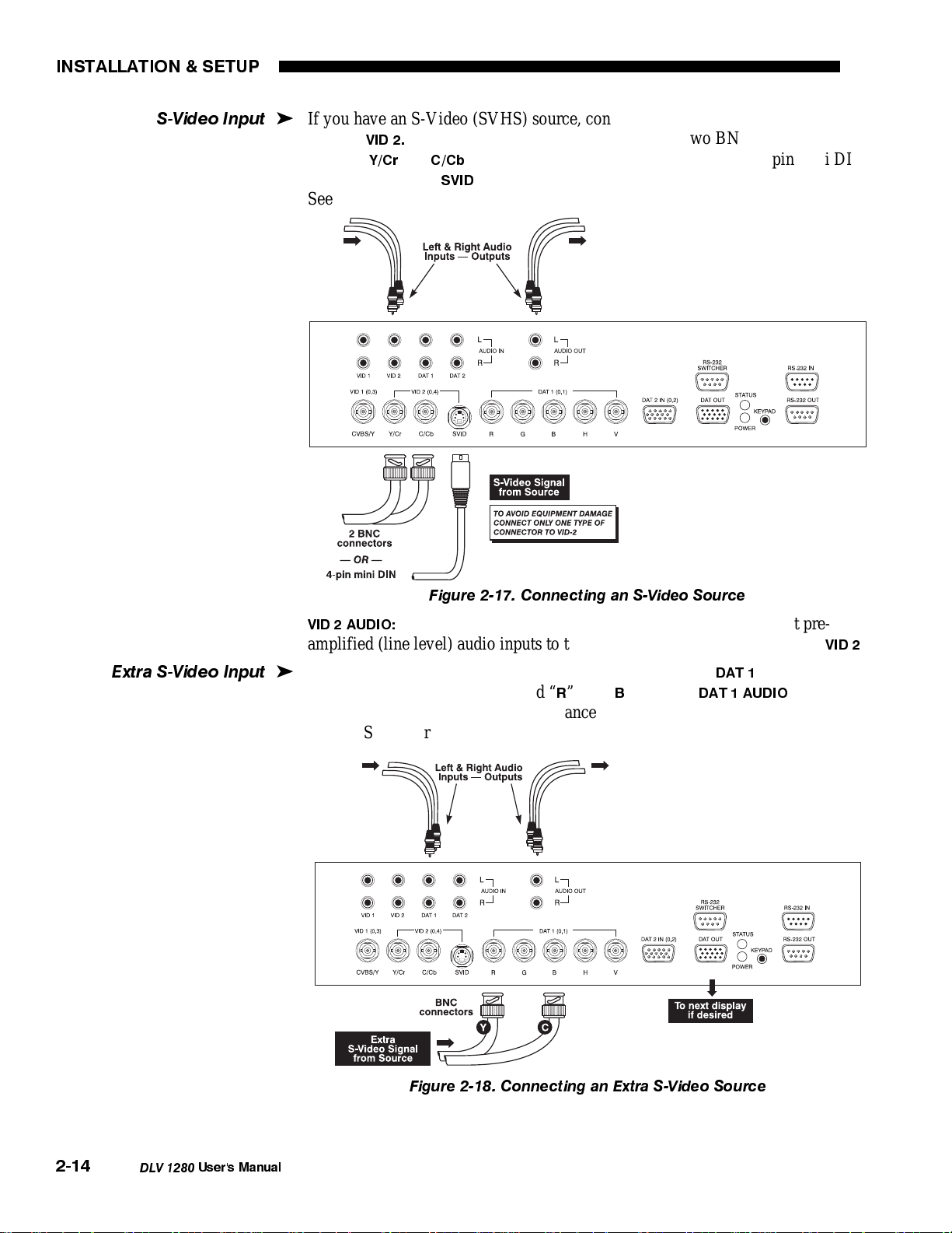
S-Video Input
If you have an S-Video (SVHS) source, connect it to the projector’s rear input
'
panel at
labeled “
connector labeled “
Depending on the source, use either the two BNC connectors
VID 2.
Y/Cr
and
” (luminance and chrominance) or use the 4-pin mini DIN
C/Cb
”— do not use both types of connectors simultaneously.
SVID
See Figure 2-17.
Extra S-Video Input
Figure 2-17. Connecting an S-Video Source
VID 2 AUDIO:
To control audio levels in an audio/visual system, connect pre-
amplified (line level) audio inputs to the left and right audio inputs labeled
If you want to connect an extra S-Video source, connect to
'
and blue BNC connectors (labeled “
” and “B”) and use
R
DAT 1 AUDIO
DAT 1
using the red
sure to connect the “Y” signal (luminance) to red, the “C” signal (chrominance)
to blue. See Figure 2-18.
. Make
VID 2
.
2-14
DLV 1280
Figure 2-18. Connecting an Extra S-Video Source
User's Manual
Page 18
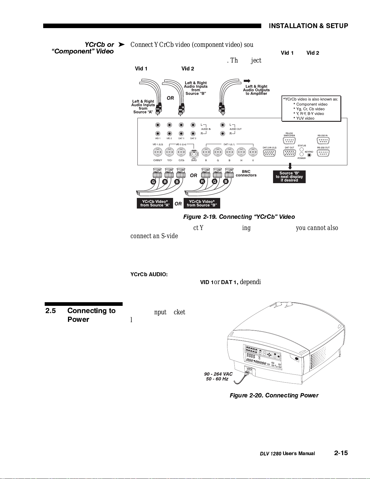
YCrCb or
Component Video
INSTALLATION & SETUP
Connect YCrCb video (component video) sources as shown in Figure 2-19. Note
'
that if you use the video inputs you will connect to both
Vid 1
and
Vid 2
simultaneously for the single source. The projector detects such a connection as
a
Vid 1
source, and
cannot be used.
Vid 2
2.5 Connecting to
Power
Figure 2-19. Connecting YCrCb Video
NOTES:1) If you connect YCrCb video using Vid 1 and Vid2, you cannot also
connect an S-video source using the 4-pin DIN. 2)DLV 1280 does not
automatically distinguish between a YCrCb signal and other RGB sources. When
using YCrCb video, turn the YCrCb option on in the Image Settings menu. See
3.6, Adjusting the Image.
YCrCb AUDIO:
right audio inputs labeled
Connect pre-amplified (line level) audio inputs to the left and
VID 1
or
DAT 1,
depending on where your video input is
connected (see Figure 2-19).
Plug the AC power cord
into the input socket
located at the left rear of
the projector (Figure 2-
20). Plug the threeprong end of the power
cord in a grounded AC
outlet. Input voltage to
the projector must be
between 90 and 264
VAC, 50 or 60 Hz. The
power source must be
capable of supplying
Figure 2-20. Connecting Power
900 watts of power to
the projector.
NOTE: Once the projector is turned off, the lamp cooling fans will continue to
run for approximately five minutes to cool the lamp. The fans will then
automatically shut off. Do not unplug the power cord before the fans stop.
DLV 1280
User's Manual
2-15
Page 19
INSTALLATION & SETUP
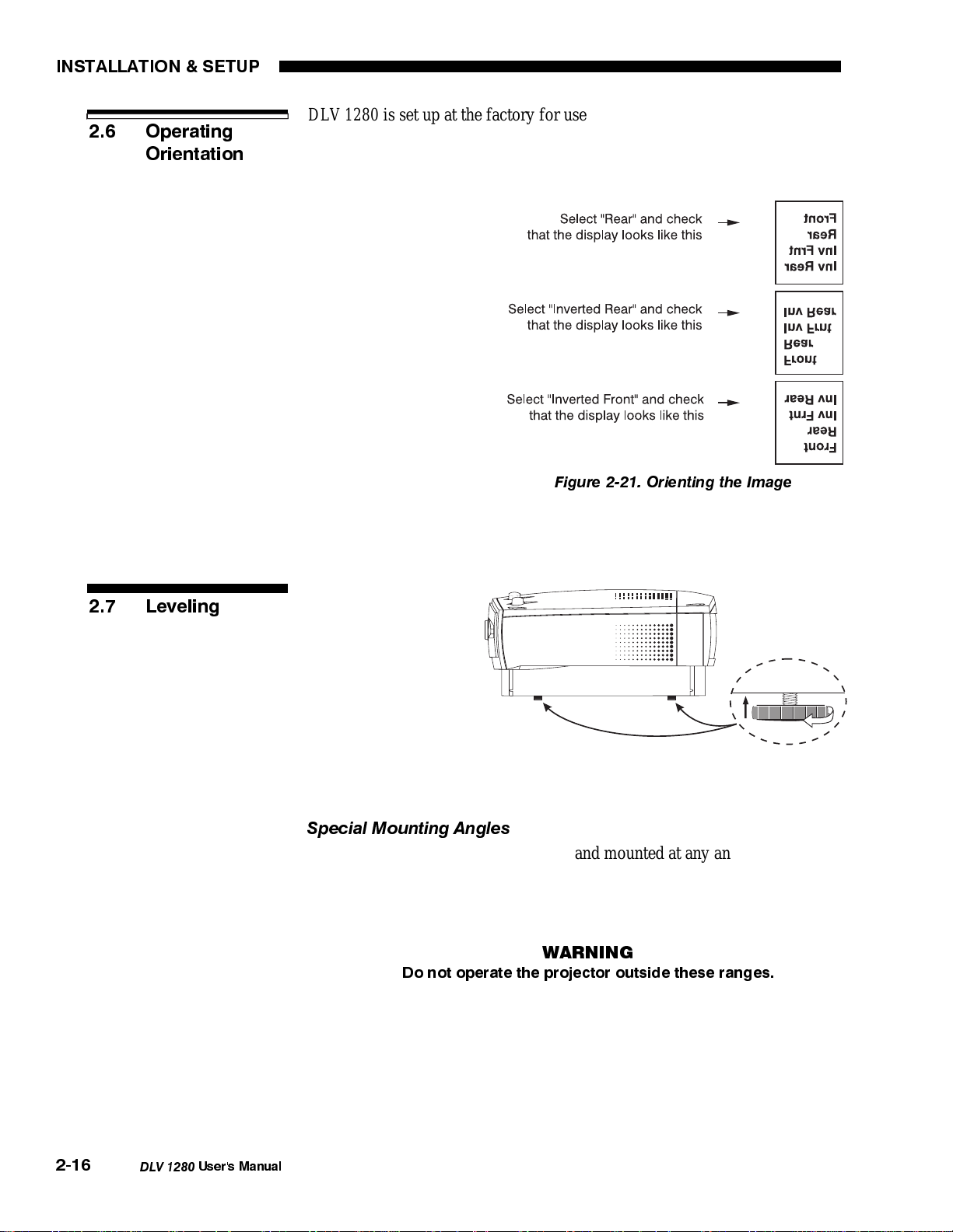
2.6 Operating
Orientation
DLV 1280 is set up at the factory for use in a front screen, floor mount
orientation. If the installation is ceiling mount or rear screen, your initial images
will likely be displayed upside down and/or reversed. To correct, you must
change the image orientation from within the Preferences menu. You may prefer
to do this before
physically installing the
projector, however it can
be done at any time. See
Section 3, Operation for
further information.
In the Preferences menu,
highlight and select the
"Orientation" option to
display a pull-down list.
From a front screen floor
mount installation, select
from Front, Rear,
Inverted Front, or
Figure 2-21. Orienting the Image
Inverted Rear according
to your intended installation. See Figure 2-21.
2.7 Leveling
For most installations
you will want to make
sure that the projector
is level from side-toside and that the lens
surface is parallel to
the screen. This will
ensure a rectangular
image that is level. To
make small corrections
to the projector's level, rotate each leg as necessary to raise or lower.
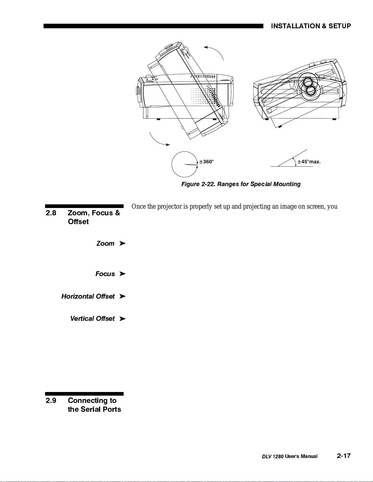
Special Mounting Angles
If desired, the projector can be rotated and mounted at any angle front-to-back.
. This limit ensures that the
The side-to-side tilt, however, must not exceed ±45
°
arc lamp in the projector operates properly and safely, and applies to all
projectors using similar lamps. See Figure 2-22.
WARNING
Do not operate the projector outside these ranges.
2-16
DLV 1280
User's Manual
Page 20
INSTALLATION & SETUP
Figure 2-22. Ranges for Special Mounting
2.8 Zoom, Focus &
Offset
Zoom
Focus
Horizontal Offset
Vertical Offset
Once the projector is properly set up and projecting an image on screen, you are
ready to make quick manual display adjustments.
If you are using a zoom lens, grasp the lens barrel close to where it enters the
'
projector. Turn it as necessary to decrease or increase the size of the image at
your current throw distance. Take care not to touch the lens surface.
Turn the outside end of the lens barrel until you obtain the best overall image
'
clarity.
Turn the Horizontal Offset adjustment knob to move your image slightly to the
'
left or right of center.
Depending on the lens present, turning the Vertical Offset adjustment knob can
'
raise or lower the image without causing keystone distortion. Turn the knob until
you achieve the desired placement of the image while maintaining its rectangular
shape. See 2.3, Projector Position and Mounting.
For further display adjustments through keypad commands and on-screen menus,
refer to Section 3, Operation.
2.9 Connecting to
the Serial Ports
Use RS-232 (serial) connections when controlling the projector with a personal
computer having an RS-232 serial interface or when using the projector with a
Marquee (or other) switcher. The RS-232 ports are located on the rear control
panel of the projector as shown in Figure 2-23.
DLV 1280
User's Manual
2-17
Page 21
INSTALLATION & SETUP
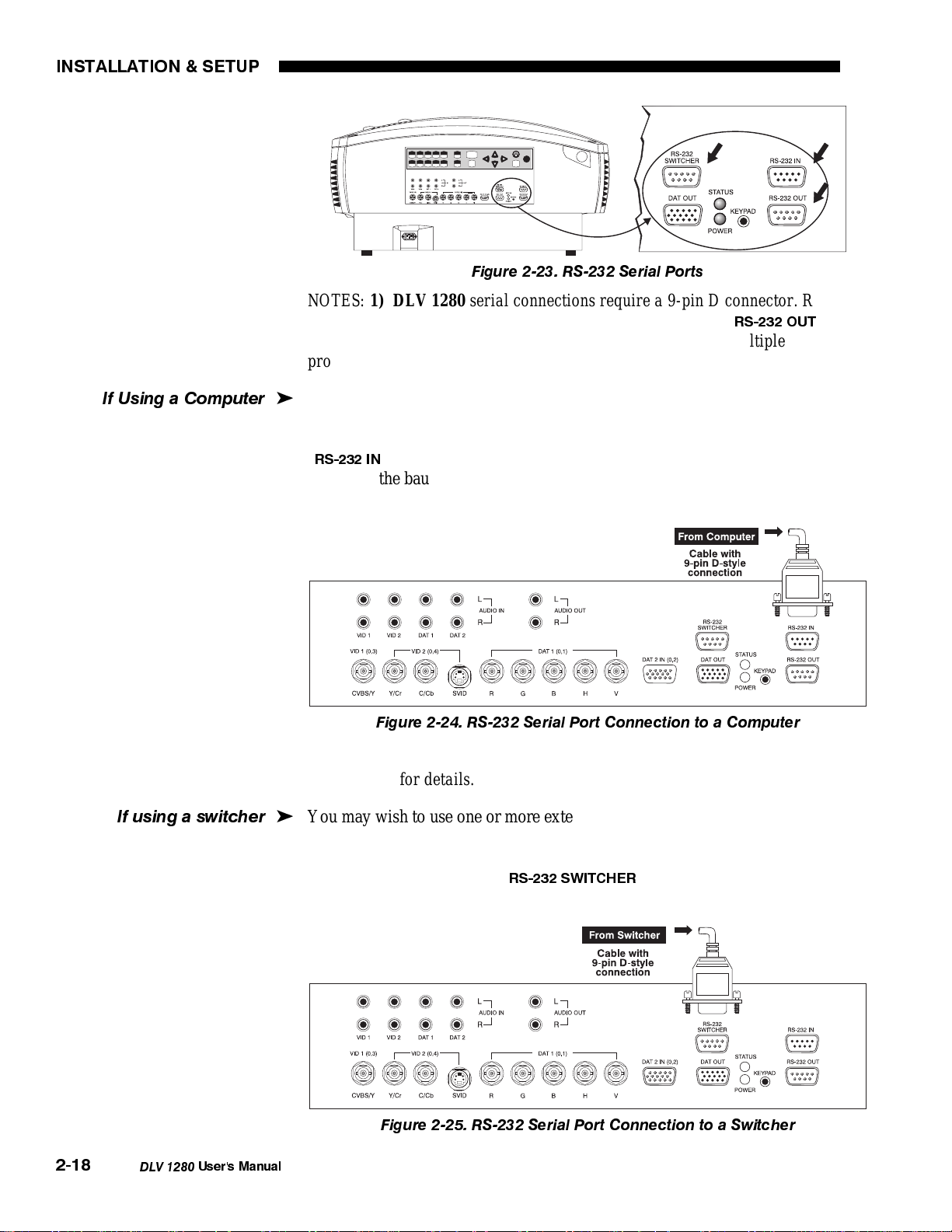
Figure 2-23. RS-232 Serial Ports
NOTES: 1) DLV 1280 serial connections require a 9-pin D connector. Refer to
Appendix D for complete cable wiring requirements 2) The "
RS-232 OUT
" port
is provided for networking applications only — see "If using multiple
projectors”, below.
If Usinga Computer
If usinga switcher
You may wish to use a computer rather than a keypad for controlling the
'
projector and for performing other special functions. Connect an RS-232 serial
communication cable between the computer and the projector serial port labeled
RS-232 IN
"
" (Figure 2-24). Then set the baud rate to match that of the computer.
Changing the baud rate is described in 3.7, Adjusting and Checking System
Parameters.
Figure 2-24. RS-232 Serial Port Connection to a Computer
Note: PC software is required for computer control. Contact your dealer or
Electrohome for details.
You may wish to use one or more external switchers, such as the Marquee
'
Switcher, in order to significantly increase the number of sources you can use.
Connect an RS-232 serial communication cable between the switcher and the
projector serial port labeled "
RS-232 SWITCHER
" (Figure 2-25). This port is
permanently set at 9600 baud.
2-18
DLV 1280
Figure 2-25. RS-232 Serial Port Connection to a Switcher
User's Manual
Page 22
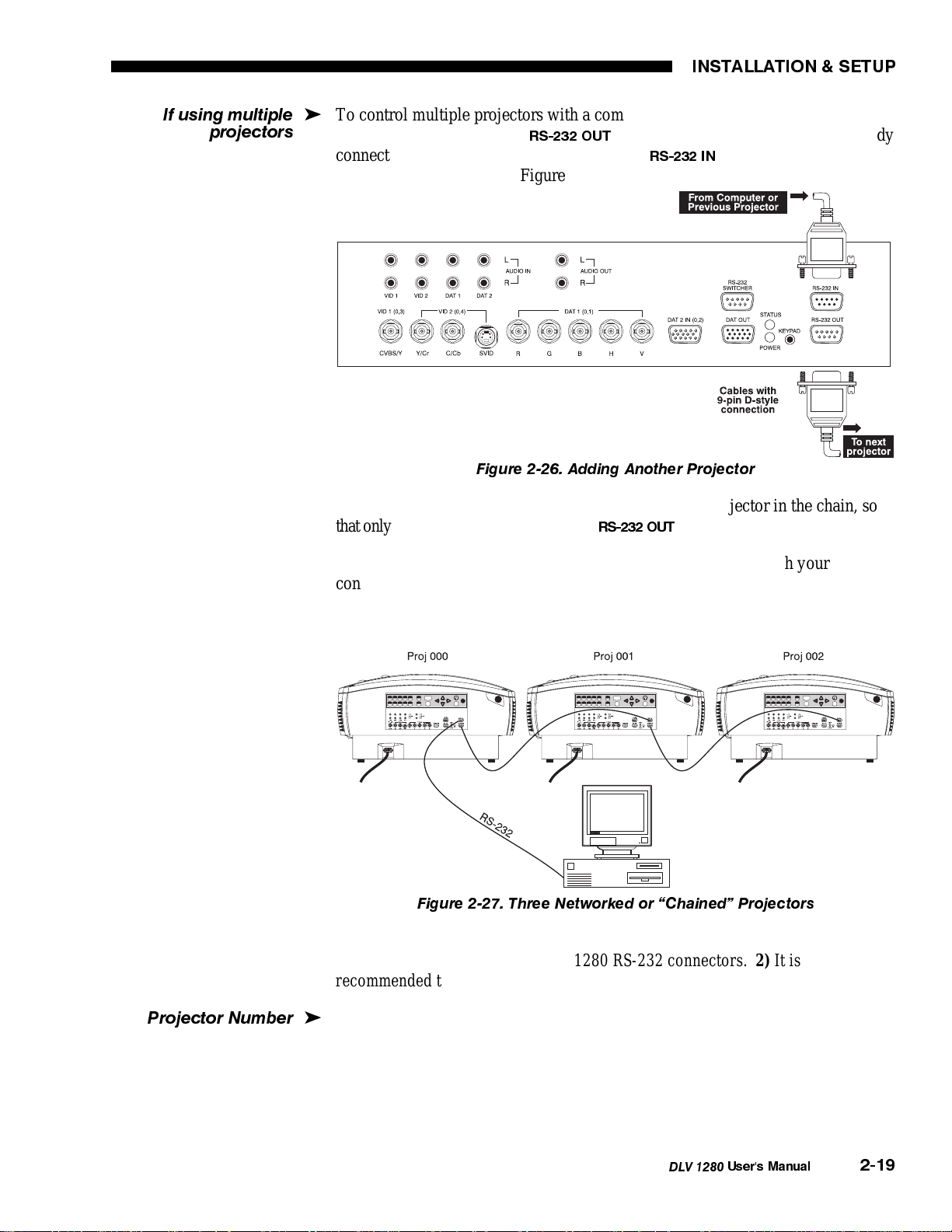
If using multiple
proj
j
ectors
INSTALLATION & SETUP
To control multiple projectors with a computer/controller, chain the projectors
'
together by connecting the "
RS-232 OUT
connected to the computer/controller) to the "
" connector of the first projector (already
RS-232 IN
" connector of the next
projector in the chain. See Figure 2-26.
Figure 2-26. Adding Another Projector
Continue connecting projectors in this way to the last projector in the chain, so
that only the last projector has an empty "
RS-232 OUT
" co n n e c t o r . S e e Figure 2-27.
Communication parameters such as baud rate must be set to match your
controlling device—refer to the documentation for the controlling device. See
3.7, Adjusting and Checking System Parameters if you need help changing the
projector baud rate from its default of 38400.
Figure 2-27. Three Networked or Chained Projectors
Notes: 1) To avoid damage, connect only properly wired RS-232 serial
communication cables to the DLV 1280 RS-232 connectors. 2) It is
recommended that each communication cable be no more than 25 feet in length.
Pro
ector Number
Each projector can be assigned a unique 3-digit projector number (for example,
'
001). These numbers are particularly useful when you are working with multiple
linked projectors, enabling you to direct commands to a certain projector rather
than broadcast to all projectors. For complete information on how to assign
projector numbers, see 3.7, Adjusting and Checking System Parameters.
DLV 1280
User's Manual
2-19
Page 23
INSTALLATION & SETUP
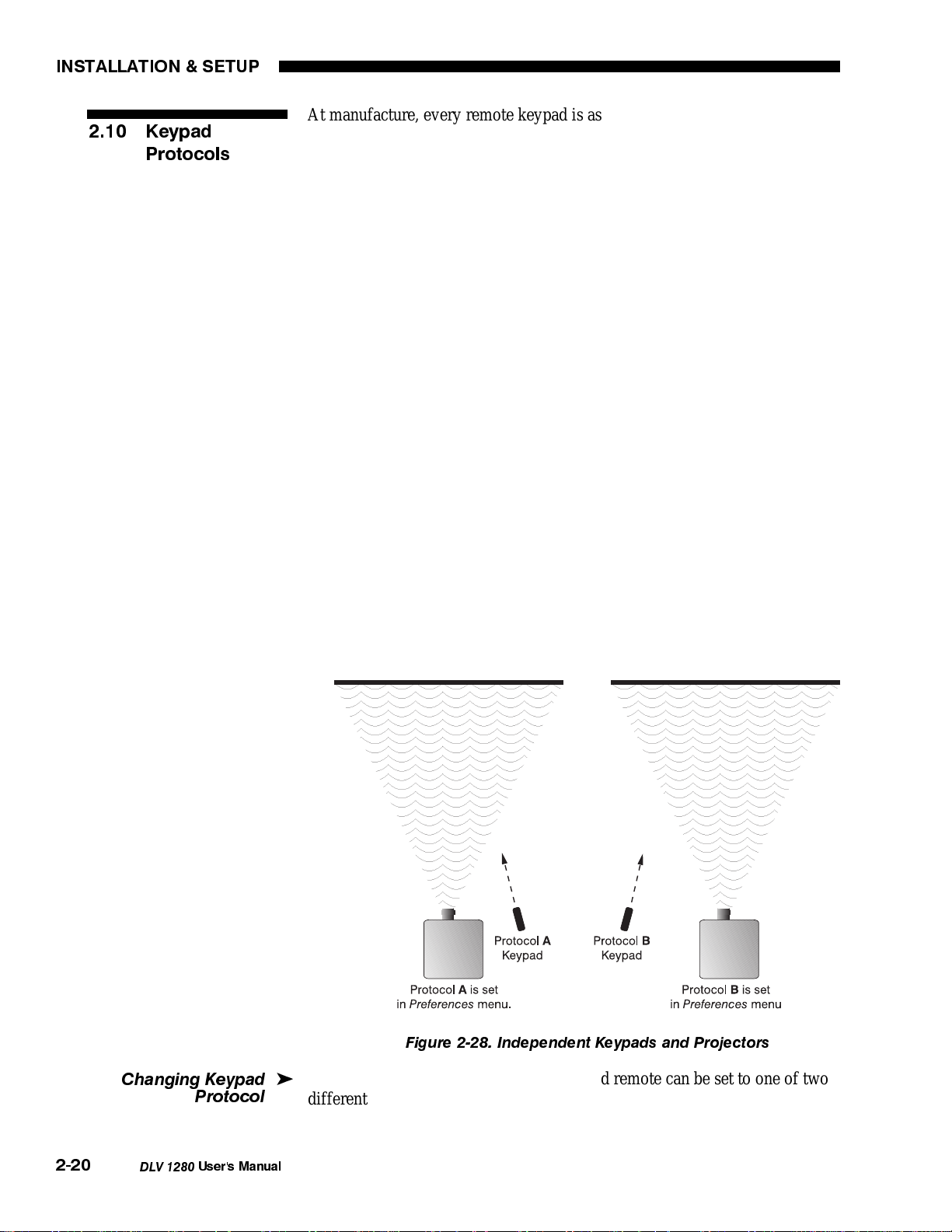
2.10 Keypad
Protocols
At manufacture, every remote keypad is assigned a default protocol, which is
simply a collection of settings that determine how the keypad operates. Once
assigned, this protocol remains in effect until it is changed — that is, the keypad
will operate as it currently does until you change its protocol.
Protocols are most useful for multiple-projector applications. For example, you
might want to change one keypad protocol if you are working with two remote
keypads and two projectors in the same room and need to control each projector
independently (Figure 2-28). When Keypad A has a different protocol than
Keypad B, each keypad communicates only with the projector having a matching
protocol. Or, if you have a network of two or more projectors connected together
via RS-232 serial ports, you may want only certain projectors to respond to a
wired keypad.
NOTE: Match the protocol on the projector to that of a keypad by setting the
desired option in the Preferences menu (use Front IR, Rear IR or Wired Keypad,
depending on which you want to change). See 3.7, Adjusting and Checking
System Parameters for further information.
A protocol for either type of remote keypad — IR or wired — can be changed
through software commands entered on the keypad. A new protocol set through
software commands remains in effect until a battery is removed (if an IR
remote), or until the keypad is unplugged from the projector (if a wired remote).
The projector will automatically detect software changes. A remote can also be
changed manually — you can "hard-wire" new jumper settings inside the keypad
so that they remain in effect permanently until you change the hard-wiring back
again. Again, to temporarily override the hard-wired protocol at any time, simply
use the shortcut software command.
2-20
Changing Keypad
Protocol
DLV 1280
User's Manual
Figure 2-28. Independent Keypads and Projectors
The IR remote keypad or the optional wired remote can be set to one of two
'
different protocols — "A" or "B". To hard-wire a protocol to "A" or "B" in
either type remote, follow Steps 1 through 6.
Page 24
INSTALLATION & SETUP
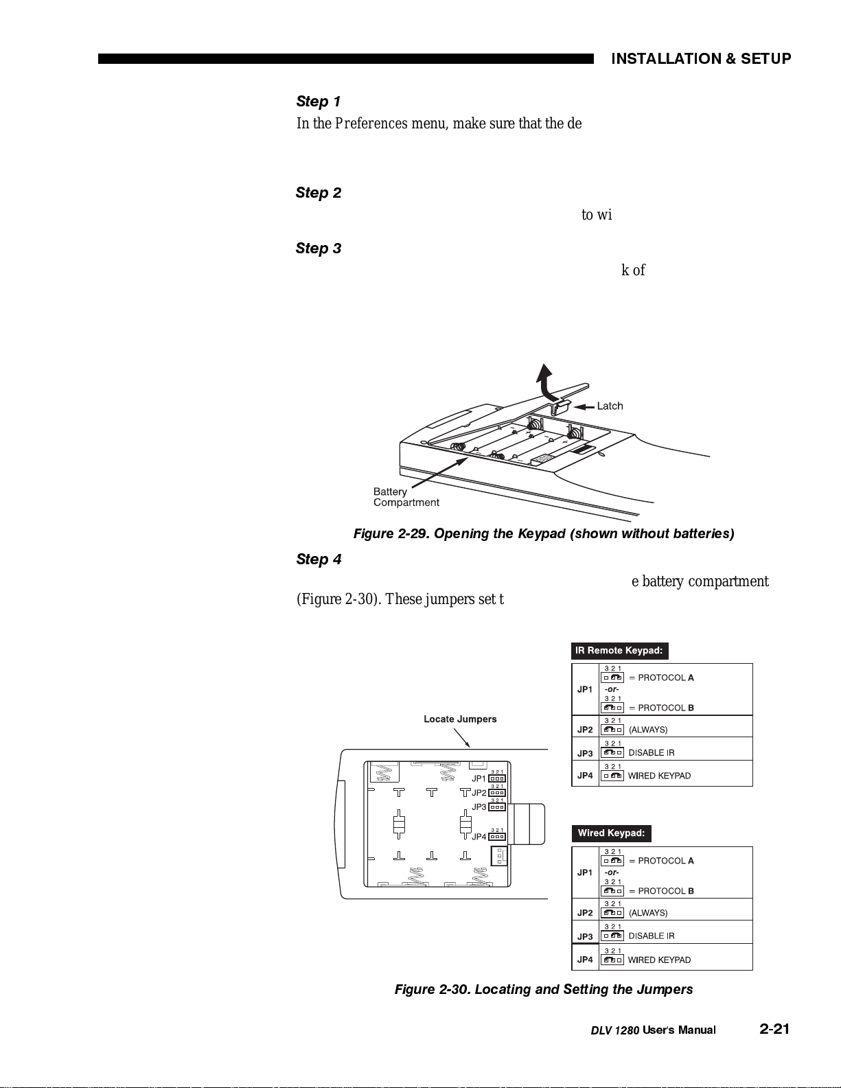
Step 1
In the Preferences menu, make sure that the desired keypad option (Front IR,
Rear IR, or Wired Keypad) is set to Option 1 “A or B”. This will ensure that the
projector will continue to respond to the keypad after you change protocol.
Step 2
Unplug the keypad from the projector (applies to wired remote only).
Step 3
Unlatch and open the battery compartment on the back of the keypad as shown in
Figure 2-29. Make sure the batteries are in place (IR keypad only).
NOTE: The optional wired keypad appears as shown, but there is a cable
passing through the battery compartment cover.
Figure 2-29. Opening the Keypad (shown without batteries)
Step 4
Find the 4 jumpers located along the latching side of the battery compartment
(Figure 2-30). These jumpers set the keypad protocol and other parameters so
that the keypad functions in a certain manner.
Figure 2-30. Locating and Setting the Jumpers
DLV 1280
User's Manual
2-21
Page 25
INSTALLATION & SETUP
Step 5: Set the Jumpers
Set the jumpers as shown in Figure 2-30. Take care to refer to the correct part of
the drawing — IR or wired (optional). Use tweezers or needle-nose pliers to
remove and replace each jumper as necessary.
•
J1
jumper: For either remote, set between pins 1 and 2 to set as Protocol
"A". Set between pins 2 and 3 to set as Protocol "B".
•
J2
jumper: For either remote, set between pins 2 and 3 as shown; otherwise,
the projector will not respond correctly to keypad commands.
•
J3
jumper: For the IR remote, make sure that the jumper is set between pins
2 and 3 as shown. For the wired remote, make sure that the jumper is set
between pins 1 and 2 as shown.
•
J4
jumper: For the IR remote, make sure that the jumper is set between pins
1 and 2 as shown. For the wired remote, make sure that the jumper is set
between pins 2 and 3 as shown.
Step 6
Replace battery compartment cover. Plug into projector (wired keypad only) and
test.
NOTE: Although they are similar, a wired keypad cannot be converted into an
IR remote keypad, nor vice versa.
SHORTCUT METHOD FOR CHANGING PROTOCOL:
You can also issue software protocol settings through the keypad. These settings
override the hard-wired jumper settings and remain in effect until the keypad is
either unplugged or until a battery is removed. At that point, keypad protocol
will then revert back to the hard-wired jumper settings (see above). Note that the
projector will automatically detect this return to hard-wired settings and will still
respond. To set the keypad protocol through software:
Press
Press
= Protocol "A"
= Protocol "B"
NOTE: If you set a remote keypad to a new protocol and the projector stops
responding entirely, the projector may be set to a conflicting protocol. Use the
projector's built-in keypad to access the Preferences menu. Under the relevant
keypad option, select the protocol that matches the new protocol of the remote
keypad. The projector should now respond properly.
2-22
DLV 1280
User's Manual
Page 26
3.1 Overview
Section 3
Operation
This section explains how to use the DLV 1280 projector once it has been
installed. Please read through this section before using the projector for the first
time, and keep it on hand for future reference. With a full understanding of DLV
1280 features and how to access them, you will be able to take complete
advantage of the capabilities of the projector.
NOTES: 1) Installation involves locating the projector and adjusting it for use at
that location. If you have not yet installed the projector, refer to Section 2,
Installation and Setup. 2) This manual assumes all audio/video options are
installed.
Organization of this section is as follows:
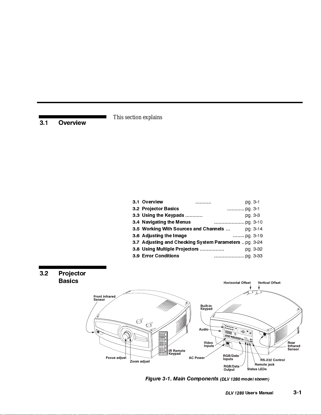
3.2 Projector
Basics
3.1 Overview
3.2 Projector Basics
3.3 Using the Keypads
3.4 Navigating the Menus
3.5 Working With Sources and Channels
3.6 Adjusting the Image
3.7 Adjusting and Checking System Parameters
3.8 Using Multiple Projectors
3.9 Error Conditions
........................................................
.............................................
.........................................
.....................................
.............
.......................................
...............................
............................................
pg. 3-1
pg. 3-1
pg. 3-3
pg. 3-10
pg. 3-14
pg. 3-19
..
pg. 3-24
pg. 3-32
pg. 3-33
Figure 3-1. Main Components
(DLV 1280 model shown)
DLV 1280
User's Manual
3-1
Page 27
OPERATION
Main components for operating the projector are shown in Figure 3-1. Notice
that only zoom, focus and lens offsets are mechanically adjusted at the projector.
Most other DLV 1280 functions and adjustments are entered through simple
keypad commands that either control the projector directly or which display a
system of easy-to-use menus. In addition, you can define up to ninety-nine
different source setups called channels for storage in the projector's internal
memory, with each channel retaining its own specific adjustment levels and
settings. Projector components are described below:
Infrared Sensors
Zoom
Focus
Lens Offset
Composite or S-Video Input
RGB Input
(with loop-through)
PC Analog Input
(with loop-through)
Data Output
(loop-through)
The infrared (IR) sensors on the front and rear of DLV 1280 receive infrared
'
signals from the IR keypad for remote control of the projector. Make sure that
these sensors are not blocked. Note: DLV 1280 CR has front sensor only.
A zoom lens barrel rotates to change the size of the image at the current throw
'
distance (projector-to-screen distance). Minimum and maximum image sizes
depend on the specific zoom lens installed (see Section 5, Specifications).
The lens barrel rotates to adjust the sharpness of the image at the current throw
'
distance.
The two lens offset adjustment knobs adjust the vertical and horizontal position
'
of the image in relation to the projector lens. See Section 2, Installation and
Setup for details.
Accepts Composite video or S-Video signals from devices such as VCRs.
'
Accepts RGB and sync signals from devices such as computers, looping through
'
to another display if desired.
Accepts PC analog signals from PCs and (with adapter) Macs, looping through
'
to another display if desired.
“Dat Out” loops a currently selected source input through to another destination
'
if desired.
3-2
RS-232 Interface
(with loop-through)
AC Line Input
Status LEDs
DLV 1280
User's Manual
Allows one or more projectors to be remotely controlled by a computer or
'
controller, and provides a communications connection for Marquee and thirdparty signal switchers.
Accepts only a AC line cord (power cord) as supplied with projector. The
'
projector requires AC power of 90 to 264 VAC, 50 to 60 Hz @ 9 amps.
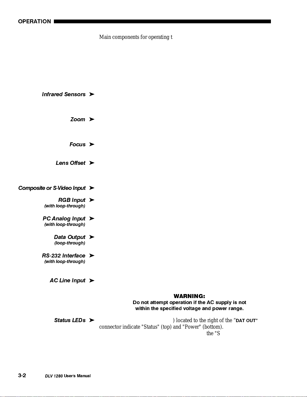
WARNING:
Do not attempt operation if the AC supply is not
within the specified voltage and power range.
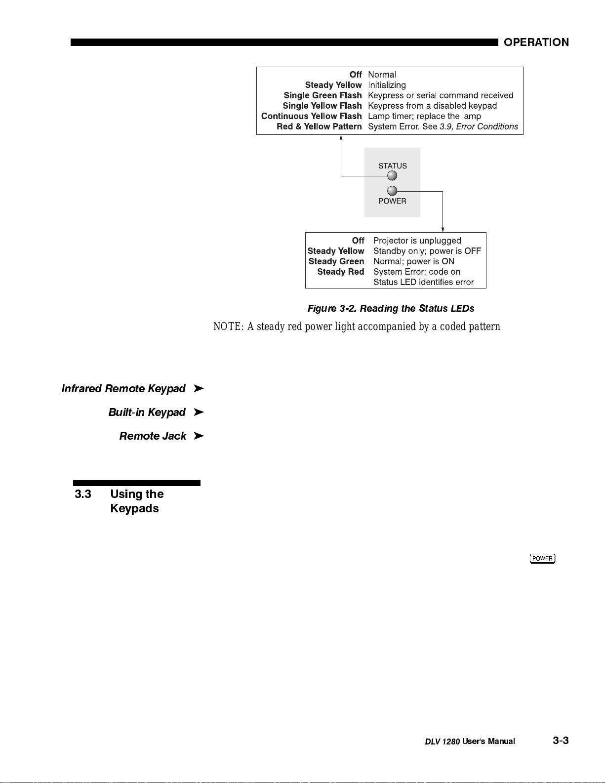
Two LEDs (light emitting diodes) located to the right of the “
'
DAT OUT
connector indicate "Status" (top) and "Power" (bottom). During normal
operation, the "Power" light is steady green and the "Status" light flashes green
each time a key is pressed or when the projector receives a serial command. Use
the following guide for interpreting the status LEDs.
Page 28
OPERATION
yp
Figure 3-2. Reading the Status LEDs
NOTE: A steady red power light accompanied by a coded pattern of red and
yellow flashes from the status light indicates an internal system error. Should the
problem persist, contact a qualified service technician through your dealer or at
Electrohome. See 3.9, Error Conditions for more information.
Infrared Remote Ke
Built-in Keypad
Remote Jack
3.3 Using the
Keypads
ad
Standard keypad for controlling the projector from a distance.
'
Alternative location on the projector for entering commands.
'
Accepts a wired remote keypad for alternative method of remote control.
'
Use any of three different keypads to control DLV 1280: The Built-in Keypad,
the IR (infrared) Remote, or the Wired Remote Keypad (optional). Each keypad
provides complete control of the projector, however you may find one keypad
more appropriate or convenient than another, depending on your specific
installation and application.
On each keypad, some keys always cause a single direct action, such as
turn the projector on or off. Direct keys allow you to perform some tasks or
adjustments quickly without going through a menu system. Other keys activate
on-screen menus.
to
DLV 1280
User's Manual
3-3
Page 29
OPERATION
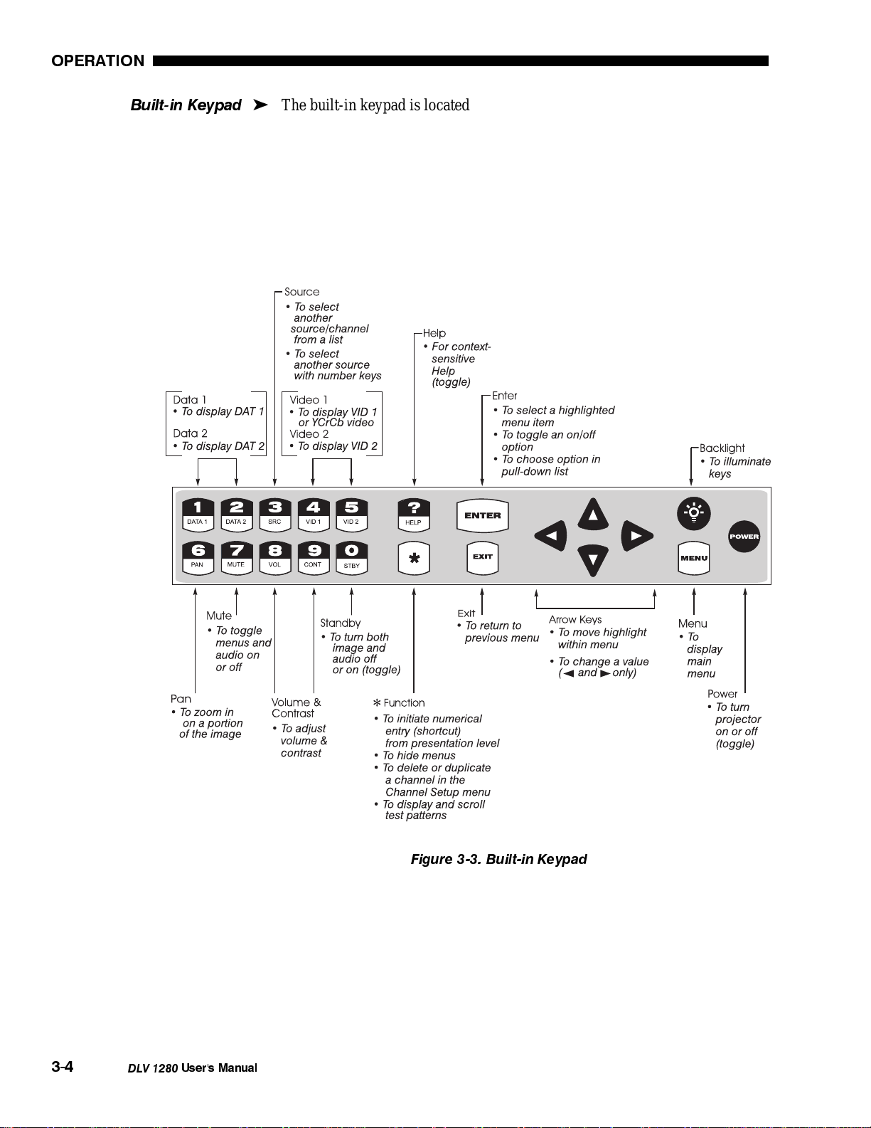
Built-in Keypad
The built-in keypad is located on the back panel of the projector.
'
Note that on this keypad, each number key also has a second label indicating a
specific function (“SRC” or VID 2”, e.g.). These second labels apply only in
presentation level, i.e., when there is no part of the menu system present.
3-4
DLV 1280
Figure 3-3. Built-in Keypad
User's Manual
Page 30

OPERATION
IR Remote Keypad
The IR Remote Keypad is the most commonly used keypad. It controls the
'
projector by way of wireless communications from a battery-powered infrared
(IR) transmitter. Use the keypad the same way you would use a remote keypad
supplied with a television or VCR. When making key presses, point the keypad
either toward the screen or toward the front or rear of the projector.
Figure 3-4. IR Remote Keypad
or Wired Keypad
DLV 1280
User's Manual
3-5
Page 31

OPERATION
Wired Remote Keypad
(OPTIONAL)
The wired remote keypad connects to the DLV 1280 remote jack via a 25 ft
'
extension cable. This keypad is particularly useful when:
• the location of the keypad in relation to the projector or screen is inadequate
for IR Remote Keypad operation.
• the lighting conditions are unsuitable for proper IR transmission
• you are controlling multiple projectors in the same room and need to control
each by its own remote keypad.
NOTE: The wired keypad layout and functions are identical to the IR remote.
Guide to Keypads
The following guidelines apply for all DLV 1280 keypads.
'
Press and release keys one at a time.
1)
You must hold down
2)
for about a second in order to turn the projector
on or off. For other keys, a momentary press similar to a mouse click is
sufficient.
Any key press temporarily illuminates the backlight for reading the keys
3)
(applies to remote keypads only).
4)
, , , ,
and
usually repeat their actions when held down. For
other keys, release and press again to repeat an action.
Any number key will function as a number within all parts of the menu
5)
system.
If you press a key while the projector is busy with another action, such as
6)
during power-up, the key press may not take effect.
When you turn on the projector it begins operating at presentation level, which
displays the image from the existing source signal. The projector temporarily
leaves presentation level when you use the keypad to change control settings,
display menus, or access on-line help. For example, pressing
after startup
displays the main menu list for access to specific functions — presentation level
remains visible but is no longer considered “active”. Pressing
) returns to presentation level.
again (or
3-6
DLV 1280
User's Manual
Keypad operating settings (protocols)
The remote keypad and the optional wired keypad both can store keypad
operating settings (also called protocols) in memory. In some advanced
applications, such as when you want to use two separate keypads to control two
projectors independently, you may want to override the original protocol (called
Protocol "A") set during manufacture. See 2.10, Keypad Protocols for complete
instructions on changing protocol.
Basic keypad commands are explained below.
Power ON / OFF
Press
and hold for approximately one second to turn the projector on or
off.
NOTES: 1) Once the projector is turned off, fans remain on for about five
minutes to cool the lamp as quickly as possible. 2) Always avoid turning the
Page 32

OPERATION
projector on and off unnecessarily — each striking of the lamp significantly
reduces lamp life.
Dat 1
Press
to select and display the input connected to
on the projector
DAT 1
(data input). Note that if a switcher is connected to Dat 1, the source on the last
selected switcher/slot will be displayed.
Dat 2
Press to select the input connected to
on the projector (data input).
DAT 2
Vid 1
Press
to select the input connected to
on the projector (normally
VID 1
composite video). Note that YCrCb video (component video) connected to the
video inputs also responds to
VID 1.
Vid 2
Press
Video, also known as SVHS).
to select the input connected to
cannot select any YCrCb video (component
VID 2
video) that may be connected to the video inputs—use
on the projector (normally S-
VID 2
.
VID 1
Source
Press
to select a source or channel Note that the precise method you use
depends on which option (from within the Preferences menu) you have chosen
for the
source location when you press
see a scrollable list of channels when you press
key. You can choose to enter the switcher and slot number for a
(this is the default), or you may prefer to
, or you may want to enter
the 2-digit channel number representing a source setup. See Preferences for
details.
Standby
Press
to blank the display and mute the audio output while keeping the
projector in a warmed-up and ready state (standby). Note that everything remains
ON even though the screen turns to black. If menus are up when you press
the projector first leaves the menu system, then goes into the standby state. To
leave standby, press
again, or .
Menu
Press
Press
at any time to display the main menu list of eight function menus.
again (or ) to return to presentation level.
Enter
Press
to select and accept a highlighted item, display a pull-down list,
toggle an on/off option, or to save an adjustment and return to the menu.
,
Exit
Press
NOTES: 1)
to return to the previous menu level.
does not save changes within text editing boxes or pull-down
lists, where it functions as an “escape” (cancel). For example, if you are moving
DLV 1280
User's Manual
3-7
Page 33

OPERATION
within a list of channels, pressing will NOT change the channel. 2) has
no effect in presentation level except to remove any test patterns present.
Arrow Keys
Use the 4 arrow keys to:
• navigate within a menu
• navigate within a pull-down list
• increase or decrease a value
or
or
Within all menus or lists,
and
keys moves up or down one option at a time.
For faster scrolling in longer menus (i.e., those showing a scroll bar), use
move to the next page of the menu, use
While in
mode, use arrow keys to reposition a zoomed (panned) image.
to move to the previous page.
Plus or Right Arrow
There are various uses for these keys, depending on the situation:
to increase a slidebar value
•
•
•
•
•
•
or
to change an on/off option to “on” (in short menus)
or
to scroll up through options in a pull-down list
or
to go to the next source (channel) in the “InMenu” list (remotes only)
to duplicate a given source (channel)
to go to the next page in a long menu (one having a scroll bar)
Minus or Left Arrow
There are various uses for these keys, depending on the situation:
•
•
•
•
to decrease a slidebar value
or
to change an on/off option to “off” (in short menus)
or
to scroll down through options in a pull-down list
or
to go to the previous source (channel) in the “InMenu” list (remotes
only)
to delete a given source (channel)
•
•
to go to the previous page in a long menu (one having a scroll bar)
to
3-8
DLV 1280
User's Manual
Function Key
Use the
key to access menus without displaying them. This direct and “blind”
access enables you to continually display an image while making a quick
adjustment. For this blind access, press
(or more) from presentation
level to use a specific menu option. Make sure to use the corresponding numbers
from the menu system. You will find that codes to the most commonly used
menu options are easily memorized and can save time.
For example, enter
to immediately display and adjust the color slidebar
without displaying the Main menu or Image Settings menu. If slidebars have
been turned off (in Preferences menu), even the slidebar will be hidden. Press
again if you ever want to recover a menu or slidebar and verify your status.
Page 34

OPERATION
NOTE: Certain engineering codes accessed through the key may freeze an
image or display an unfamiliar menu. Should you accidentally select one of
these special codes, press any non-number key to cancel and return to
presentation level.
Cont
Vol
The
key can also access certain other functions outside the menu system, such
as test patterns and certain commands from the built-in keypad. For details, see
Service menu later in this section.
Contrast
Press to increase or decrease the difference between light and dark areas of
your image. Use
and until you reach the desired level of contrast, making
sure that whites do not distort or become tinted. Note that after 5 seconds of
inactivity the Contrast slidebar disappears and the previous menu or presentation
level reappears.
NOTE: On the IR or wired remote, you can select either the
or “Cont”
keys to begin increasing or decreasing the degree of contrast in the image. See
3.6, Adjusting the Image (Image Settings subsection) below.
Bright key
or
Select either the
"Bright" key to begin increasing or decreasing the
amount of perceived light in the image so that black just changes to very dark
gray. See 3.6, Adjusting the Image (Image Settings subsection).
NOTE: Remote keypads only.
Volume
On the built-in keypad, press
current source or channel. Use
to turn on or control the audio level for the
and until you reach the desired volume.
Note that after 5 seconds of inactivity the volume slidebar disappears and the
previous menu or presentation level reappears.
NOTE: On a remote keypad, select either the
or “Vol” key to raise or
lower the volume.
Projector Key
Press
to display an editable box indicating which projector is active and
currently listening to the remote keypad. To control a single projector within a
group, enter the 3-digit number assigned to the projector you want to use, or use
or to scroll. Press to select.
To broadcast to multiple projectors, do one of the following on a remote keypad
(a built-in keypad controls only its local projector):
• press
• press
+
+
NOTES: 1)If the editable box is displayed and you want to select a different
option in the Preferences menu, use the arrow keys rather than a number key.
2) See 2.10. Keypad Protocols, 3.7, Controlling System Parameters and 3.8,
Using Multiple Projectors.
DLV 1280
User's Manual
3-9
Page 35

OPERATION
Pixel Track
or
Select either the
"Pixel Track" key to begin increasing or decreasing the
frequency of the pixel sampling clock to match the input signal. Pixel tracking
may need adjustment when your image is stretched or compressed (assuming it is
sized correctly) and exhibits soft vertical bars of noise. See 3.6, Adjusting the
Image (Image Size & Position subsection).
NOTE: Remote keypads only.
Pixel Phase
or
Select either the
"Pixel Phase" key to begin increasing or decreasing the
phase of the pixel sampling clock so that any shimmer disappears and the image
is stable. See 3.6, Adjusting the Image (Image Size & Position subsection).
For continuous automatic adjustment, press
and an “
” will appear in the menu to signify that the projector has selected the
A
. The phase value will change
correct phase setting for the current display. To toggle auto phase off, press
again.
NOTES: 1) This key is on remote keypads only. 2) Pixel Tracking must be
correct in order for Pixel Phase to work.
Mute
At presentation level, press
off. A small “MUTE” message will appear until you cancel (press
If a menu is visible, press
to toggle audio from the current source on or
or ).
(or on the built-in keypad) to hide it. You can
continue adjustments as usual with the arrow keys while displaying only the
image. To cancel mute and return to the normal menu display, press any key
other than the right or left arrow keys, or
or .
If you are hiding the menus (i.e., you entered the menu system “blindly” with
), press
or to re-display the menus.
Pan
Press
as extremely small text or some sort of detail. Each press of
through the zoom factors of
if you want to enlarge (zoom in on) only a portion of the image, such
will scroll
(normal state of image), x2 (doubled) and
Off
x3
(tripled). Use the arrow keys to move the portion you want to see into view.
3.4 Navigating
the Menus
3-10
DLV 1280
User's Manual
Help
Press for detailed information about any current menu and highlight. Press
again to exit. From presentation level, press
to access the General Help
menu consisting Using Help, Setup, Keys, Source Selection and Status and
Power LEDs. Press
to exit and return to presentation level.
Most of the controls for the projector are accessed from within the DLV 1280
menu system, consisting of a main menu from which eight function menus and
other options stem. See Appendix C for the complete DLV 1280 menu tree.
Page 36

OPERATION
Main Menu
Function Menus
Press at any time to access the Main menu. This menu lists all function
'
menus.
Figure 3-5. Using the Main Menu
In the Main menu, use the arrow keys to highlight the function menu you wish to
access, then press
to display it. Or, for quicker access with less manual
scrolling, simply enter the number of the desired menu. For example, enter
(in the Main menu) for Image Settings or
for Preferences. The desired
function menu will appear.
Function menus are accessed through the Main menu. They are Auto Setup,
'
Image Settings, Horizontal Settings, Vertical Settings, Preferences, Channel
Setup, Service, and Status.
Once in a function
menu (such as
Preferences, left),
use the arrow keys to
move the highlight to
a desired option.
Then press
select it. Or simply
press the appropriate
number key for
quicker access to any
numbered menu item.
If a menu is longer
than a single page
Figure 3-6. Sample Function menu
(indicated by the
presence of a scroll
bar on the right side), use
to go the next page and
to return to the previous.
If items are locked out or do not pertain to the current action, the highlight will
skip over them and you cannot select them, although they remain in the list. If
there is no signal present all source-dependent adjustments are disabled. Also
note that after 15 minutes of inactivity, a function menu disappears and the
projector returns to presentation level.
to
When you are finished with a function menu, do one of the following:
• Press
• Press
to return to the previous menu level (usually the main menu).
to accept any changes made and return to the main menu.
DLV 1280
User's Manual
3-11
Page 37

OPERATION
g
p
Hidin
the Menu System
On-line Hel
NOTE: See Appendix C for the complete DLV 1280 menu tree.
'
If you like, you can change a setting directly from presentation level without
seeing on-screen feedback. This “blind” access enables you to continually
display your image while making a quick adjustment. From presentation level,
simply press
(or more), using the corresponding numbers from the
menu system to immediately access a desired option. Note that options in pulldown lists may be numbered as well, so include this extra number in your entry.
For example, enter
while suppressing both menus and slidebar. Press
to change the color level for the current image
again if you want to
recover a menu or slidebar and verify your status. If you are accessing an on/off
option, direct access immediately toggles the current setting.
Use the arrow keys as usual to go to another menu item or option.
If at any time you are uncertain about a menu or highlighted option, press
'
to display detailed information about it. Once in Help, use the arrow keys to
scroll as necessary. Press
again (or
) to leave help, or press to
exit and return to the main menu.
Or, if you are at presentation level with no menu displayed, press
General Help topics. Press
to return to presentation level.
to access
Using slidebars and
other controls
Within most function menus you can change various settings through slidebars,
'
on/off toggles, and pull-down lists. Highlight the menu item (parameter) that you
want to adjust. If it is a slidebar, adjust it as desired (see below). For other menu
items, press
to reverse an on/off status, or display a pull-down list.
Slidebars
A slidebar is a simple graphic representing the current value for the given
parameter, such as a brightness or contrast setting. The numerical value appears
in the right corner above the slidebar. This number usually represents either an
actual amount (such as number of pixels) or a percentage (such as 77%
brightness).
To adjust a slidebar up or down:
(remote keypad only)
• Press
or
• Or press or
• Or press
(note: does not apply to Pixel Phase option)
and enter a specific value
As soon as you increase or decrease the level, both the number and the length of
the bar change accordingly. Press
to return to the function menu.
NOTE: If you use a slidebar directly from presentation level, you must enter a
change within 5 seconds or the slidebar will disappear from the screen.
3-12
DLV 1280
User's Manual
To turn all stand-alone (non-menu) slidebar graphics off so that you can adjust
settings without displaying any slidebars, set the “Display Slidebars” option to
” in the Preferences menu.
Off
“
Page 38

On/Off
g
Some options are either on or off, such as “Broadcast Key”.
To toggle an option on or off:
OPERATION
• Press
• Press
• Press
Note that in Preferences and Channel Edit menus, the
(on)
(off)
to toggle between on and off
and arrow keys
change the menu page rather than toggling an on/off option. Use one of the other
keys in these menus.
Pull-down Lists
Some options can be set to one of several specific values or settings, such as
“Baud Rate” or “Orientation”. Press
to see the pull-down list of possible
settings for an option.
Figure 3-7.Using a Pull-down List
Editin
Text
To select an item in a pull-down list:
• Press
• Press
• Press a
• Press
NOTE: Press
To edit a text parameter (such as a channel name), highlight the desired
'
parameter and press
to move down in the list, then press to save.
to move up in the list, then press
key corresponding to a numbered option
to cancel (escape). Original setting remains.
to save.
or to cycle through a pull-down list without displaying it.
to enable the text editor. The highlight will shrink to
the edit area, where you can begin entering characters or digits.
• Press
• Press
to move to the next letter in the alphabet or to a higher number
to move to the previous letter in the alphabet or to a lower
number
• Press
to move right
• Press to move left
• Press
to insert a space
• Press to delete a character or number
• Press to save the complete entry
• Press to cancel (escape). Original text remains.
DLV 1280
User's Manual
3-13
Page 39

OPERATION
g
NOTES: 1) Numbers are at either end of the alphabet. If desired, scroll with
or . Or enter numbers using the number keys on the keypad.
Enterin
Numbers
Time-outs
When a number is required, such as when you are specifying a projector number,
'
a special highlighted numeric field appears on screen. Press a numbered key on
the keypad to begin entering the desired number. Note that once you enter the
first digit, it replaces all of the old.
• To delete the last digit entered press
• To cancel (revert back to the old number), press
at any time
• To accept the new number, press
Whenever the projector is not at presentation level, such as when there is a
'
slidebar, menu, message or test pattern present, you have limited time in which
to make a keypad entry before the projector returns to presentation level. These
time-outs vary depending on the specific function at hand, as shown in the
following chart:
TIME-OUTS
Display Time-out
All menus and options 15 minutes
Slidebar (direct access) 5 seconds
Source entry 5 seconds
Direct control entry 5 seconds
Other 15 minutes
3.5 Working With
Sources and
Channels
Selectinga Source
NOTE: See Section 2, Installation and Setup, for a complete explanation of how
to connect the various types of sources to the projector.
Once you connect a source to the projector, such as a VCR or computer, you can
'
display the image from it by pressing the appropriate “direct” key:
or
Or, perhaps if your system includes many sources, press
at any time.
to use another
method of selection. Depending on how you have defined it from within the
Preferences menu, the
•
A pull-down list
key will trigger one of the following:
of channels retained in projector. Highlight and press
to select the desired channel. Or press to cancel and return to
the present channel. Note too that you can cycle up or down through this
list of channels simply by pressing
or from presentation level.
NOTE: Only those sources marked as “In Menu” (default) in the Channel
Edit menu appear. See Editing Channels, below.
2-digit channel entry
•
of channel numbers representing source setups
retained in projector memory.
, ,
3-14
DLV 1280
User's Manual
•
Switcher & Slot entry
of a source location (default). First enter the number
of the switcher used, then enter the number of the slot for the source.
Page 40

OPERATION
g
p
NOTES: 1) A source number in the pull-down list identifies a particular channel
retained in projector memory. A “switcher/slot” number identifies the physical
location of a source. 2) If you pause for 5 seconds or more during a source
switch, the switch is canceled and you’re returned to the present source.
See Preferences section to set your desired method of source selection.
Creatin
a Channel
Once you have requested an image from a source, the image will be displayed
'
according to the input and signal parameters—the channel—last defined for that
source. If you have not yet defined any parameters that match the source, a new
channel is temporarily defined according to a default mode table defined in the
projector, and the image will initially be displayed based on these defaults. Note,
however, that this source will not be permanently saved as a new channel unless
you change a parameter (size, phase, etc.) either manually or through an “
” (see below).
Setup
You may want to adjust and define a wide variety of display parameters for a
channel, such as brightness, contrast, tint, etc., in order to optimize the display
for that source. For example, the display settings you choose for a VCR source
may be quite different from those you choose for a high resolution computer
source. Once defined, settings for a particular source are collectively stored in
the projector's memory as a unique source setup called a channel. DLV 1280 can
store and automatically recall up to 99 channels so that you do not have to
repeatedly re-configure the projector whenever returning to a previously used
channel. Note that you can have more than one channel for the same physical
source.
NOTE: A new channel is assigned the first available number from 1-99. You can
change this number in the Channel Edit submenu.
Auto
Auto Setu
To quickly adjust a new image for which initial default settings may not be ideal,
'
select “
Auto Setup
” in the Main menu. A dialog box will appear, at which point
you can either continue with the Auto Setup or cancel (see Figure 3-8). If you
continue, the following settings will be calculated automatically, filling the
horizontal width as closely as possible based on the source present:
•
Size and Position
•
Brightness & Contrast (set to defaults)
•
Pixel Tracking
•
Frame rates (input/panel) are matched
if possible
•
Top/Left Blanking (set to 0)
•
Pixel Phase
•
RGB Drivelevels (set to defaults)
•
RGB Blacklevels (set to defaults)
An Auto Setup for non-video images takes
up to 30 seconds. Auto Setup can be
canceled at any time by pressing
any time.
While auto setup can save time and effort
in setting up a new source, you may still
Figure 3-8. Auto Setup Dialog Box
want to improve some adjustments
manually, especially if the setup was based
on a dark, moving or poor quality image. For best results, use a fully bright and
stable image that entirely fills the screen.
at
DLV 1280
User's Manual
3-15
Page 41

OPERATION
NOTE: 1) Auto Setup can fail if the image content or quality is not suitable. 2)
An Auto Setup of a video image takes only an instant rather than 30 seconds.
About Channels
'
The Channel Setup Menu
A channel is automatically created and stored in memory when an input signal is
sent to the projector and you change a parameter (either manually or with an
Auto Setup). To learn more about channels, press
to display the Channel
Setup menu.
This menu lists all channels
defined so far. If there are more
channels than can be displayed
at once, press
to scroll to the
next page.
NOTE: To see more information
about a certain channel, enter
the number, or highlight the
desired channel and press
. This will activate the
Figure 3-9. Channel Setup Menu
Channel Edit menu (see Editing
Channel Setups, below).
CHANNEL NUMBER AND m:
from 01-99 and listed in the first column of the
Every defined channel is identified by a number
Channel Setup
menu. These
numbers appear in the channel list that may be displayed when you use the
key.
m
” after a number signifies that this channel will be included in the channel
An “
selection menu (also known as the
NOTE: By default, a channel will have an “
channel list
m
) available from the
” here, thus the channel will
appear in the channel list that may appear when you press
channel from the menu, you must specify “
” in the "
Off
In Menu
. To delete a
" option in the
key.
Channel Edit. See Editing Channels, below.
AUTO SOURCE:
source”. Locked sources are marked with an “
The second column identifies two states, “locked” and “auto
l
” in this column. Sources that the
projector can automatically switch to or away from whenever the input signal
a
changes are marked with an “
” (default). The projector uses the channel best
suited to the input signal. To turn the auto source off or on for a channel, use the
Channel Edit
SOURCE (CHANNEL) LOCATION:
menu (see
Editing Channel Setups
The third column consists of two digits (for
, below).
example 0,1) that identify the location of each channel according to its switcher
number (first digit) and slot number (second digit). Note that the projector is
considered to be switcher “0”, with other switchers identified as 1-9. Slot
numbers for the projector are:
•
•
•
= switcher 0, slot 1
= switcher 0, slot 2
= switcher 0, slot 3
3-16
DLV 1280
User's Manual
Page 42

OPERATION
To Delete Channels
•
= switcher 0, slot 4
Slot numbers for other switchers can range from 1-9.
FREQUENCIES (READ-ONLY):
The last two columns list the horizontal and
vertical frequencies for each channel. Or, if you have entered a name for the
channel, it will appear here instead.
'
Deleting One Channel
Channel Setup
In the
menu, highlight the channel you wish to delete and press
. A confirmation box will appear to make sure you really want to delete the
selected channel (see left). Highlight the
desired response and press
.
NOTE: The built-in keypad has no
key. Instead, press if you want to delete a
highlighted channel. This will display the
confirmation box.
If you delete the current channel, another new default channel will be created
(saved in memory only if a parameter is changed). This channel will appear in
Channel Setup
the
menu the next time you are in it, and will be assigned the
lower available channel number.
or
To Duplicate a Channel
Deleting Multiple Channels
Channel Setup
In the
menu, highlight the “Delete All Channels” and press
. A confirmation box will appear to ask which channels to delete: all, only
the unlocked channels or cancel (see left).
Highlight the desired response and press
.
'
In the
press
. The selected channel will be duplicated and assigned the next available
menu, highlight the channel you wish to duplicate and
Channel Setup
number. This new channel becomes highlighted in the menu.
NOTE: The built-in keypad has
no
channel. A dialogue box will
appear, asking if you want to
either duplicate or delete the
selected channel. Select
Duplicate or Cancel.
or key. Instead, press
if you want to duplicate a
EditingChannels
'
You can edit a channel at anytime from with the
through the
Channel Setup
menu. For example you may wish to add a
Channel Edit
DLV 1280
User's Manual
menu, accessed
3-17
Page 43

OPERATION
recognizable name for a certain channel (such as “vhs2” or “pc”), lock a channel
from further changes, or include another channel in the channel list menu.
The Channel Edit Menu
From the Channel Setup menu, highlight the channel you wish to edit or see
further information about. Press to display the Channel Edit menu for this
channel.
Highlight and select an editable
parameter here.
Figure 3-10. Channel Edit Menu
NAME:
To enter or edit the channel name (maximum of 8 characters), press
and then:
• Press
• Press
• Press
to move to the next letter in the alphabet or a higher number
to move to the previous letter in the alphabet or a lower number
to move right
• Press to move left
• Press
to insert a space
• Press to delete a character or number
• Press to accept all when done
• Press to cancel (escape). Original text remains.
Remember to press
after each character or digit you want. You can enter
numbers directly from the keypad.
CHANNEL (SOURCE) NUMBER:
To change a channel number, press the desired
number (1-99) on the keypad. If the number you enter has already been assigned,
you will be asked if you want to delete the other channel. Select “
” to cancel
Off
the change and retain the other channel number.
SWITCHER NUMBER:
This number identifies the switcher to which the source is
connected. The projector is considered to be a switcher and is always identified
as switcher “
”, with other switchers identified as 1-9. Edit as necessary.
0
3-18
DLV 1280
User's Manual
SLOT NUMBER:
This number identifies the slot to which the source is connected.
On the projector, these slots are:
• slot 1 =
DAT 1
• slot 2 =
• slot 3 =
• slot 4 =
Page 44

OPERATION
Slot numbers for other switchers can range from 1-9. Edit as necessary.
LOCKED:
IN MENU:
Select “On” to prohibit any changes to the channel, “
Select “On” if you want this channel to appear in the channel selection
menu that may appear when you press
. Select “
” (default) to prevent it
Off
” to unlock.
Off
from appearing in the channel selection list.
AUTO SOURCE:
Select “On” (default) if you want the projector to automatically
switch to or away from this channel when the input signal changes
(recommended).
SYNC TYPE:
Read-only, showing the type of signal for which this channel is
defined, such as “Composite.”
H-SYNC and V-SYNC:
These read-only parameters show the frequencies and
polarity (“pos” or “neg“) for a channel. These numbers enable selection of the
correct channel setup for the current source. If these are blank, there is no sync
present or detectable.
UPDATE:
Select this option to reset all image parameters for the current channel
to their defaults. This is useful if you specifically wish to re-define a channel
according to default values or if you want to change the source for a channel. A
message of “reading New Values” appears on screen during an update.
3.6 Adjusting the
Image
Image Settings
Various image controls lie in three function menus: Image Settings, Horizontal
Settings or Vertical Settings, each of which is called up by its own name in the
Main menu. Or, if desired, call up an individual image control directly from
presentation level by pressing the
key followed by the appropriate numbers
representing the numbered menus and options you want.
While in any of the function menus (each described below), you can adjust
settings for the current image by working with the available slidebars, on/off
options and pull-down lists. When you are done with a function menu, press
to accept changes and return to the previous menu.
Use this menu to adjust all settings for the current image except its size and
'
position. In Image Settings, adjust brightness, contrast, color, tint, or color
temperature as well as its video standard and others. Refer to Using Slidebars
and Other Controls if you need help in selecting options and accepting changes.
DLV 1280
User's Manual
3-19
Page 45

OPERATION
To return to the main menu, press .
Figure 3-11. Image Settings Menu
Contrast
CONTRAST
increases or decreases the perceived difference between light and
dark areas of your image (0-100). Adjust so that whites remain bright but not
distorted or tinted. If contrast is set too high, the light parts of the image lose
detail and clarity. If set too low, the light areas will not be as bright as they could
be and it may be difficult to distinguish between foreground and background
information.
NOTES: 1) For best results, adjust contrast AFTER brightness. 2) If room
lighting changes, it may be necessary to re-adjust both.
Brightness
BRIGHTNESS
increases or decreases the amount of perceived light in the image
(0-100). If video or data is displayed with a black background, adjust until the
background just changes from black to very dark gray.
Color
COLOR
increases or decreases the amount of color in a video image—i.e., its
color saturation level. For example, setting Color to "0" produces a black and
white image. If Color is set too high, the color levels in the picture will be overpowering and unrealistic. Use
or until the desired color saturation level is
displayed.
Tint
adjusts color hue to obtain true color reproduction of NTSC video signals.
TINT
Use
or until the you reach optimum balance of red-to-green in your image.
For best results, adjust tint while displaying a proper test pattern—otherwise, tint
should remain at its default setting.
VCR
should be “On” if you are using a VCR or if you need to reduce flag-waving
VCR
(bending) in your image. The projector will have more tolerance for poor signals,
thus it will more easily recognize and lock onto your VCR signal without
jumping to another channel. Set to “
” for non-VCR sources, or if the option
Off
creates an objectionable amount of noise in the image.
3-20
DLV 1280
User's Manual
YCrCb
Turn
YCrCb “On
” only if the input video signal is 3-wire component video (also
known as “YUV” or “Y, R-Y, B-Y” video). Laser disks are common sources of
YCrCb video. Keep this option off for other signals.
Page 46

OPERATION
g
Standard
STANDARD
indicates what video standard is currently being used for decoding
the source video signal. Generally the projector automatically recognizes a signal
and applies the proper standard. If necessary (such as for PAL-N, a black-andwhite signal, PAL-M, or a poor quality signal), use the pull-down list to select a
specific standard for the projector to use. For best results, leave
Auto.
Standard
set to
The projector decodes using the following standards:
• NTSC (also known as NTSC-M or NTSC 3.58)
• NTSC 4.43
• PAL-M (must be set in the pull-down list)
• PAL-N (must be set in the pull-down list)
• SECAM
Color Temp.
COLOR TEMPERATURE
(expressed in degrees Kelvin) adjusts “coloration”
(reddish or bluish) of the whites displayed—the lower the temperature, the more
reddish the whites. Use
or as desired for the current channel.
Horizontal Settin
s
Use this menu to adjust the width of an image or move it left or right. Refer to
'
Using Slidebars and Other Controls if you need help in selecting options and
accepting changes.
To return to the main menu, press
Figure 3-12. Horizontal Settings Menu
.
H-Pos
HORIZONTAL POSITION
moves the image left or right.
H-Size
HORIZONTAL SIZE
adjusts the width of the image. Values for H-size have the
following meanings:
• 1000 = 1:1 size
• 2000 = 2:1 size
• 3000 = 3:1 size
Pix Track
PIXEL TRACKING
adjusts the frequency of the pixel sampling clock, indicated by
the number of pixels per line, so that all pixels generated by a particular source
DLV 1280
User's Manual
3-21
Page 47

OPERATION
are sampled. Proper pixel tracking may need adjustment when your image is
stretched or compressed and exhibits soft vertical bars of noise. For best results,
adjust pixel tracking from within a smooth gray test pattern made up of a clear
pattern of tiny black and white dots, or a similar graphic image. Adjust until the
noise either disappears or fills the image completely. When noise fills the image,
adjust pixel phase to eliminate it.
Or, if you know the resolution of your source, you may prefer to use a different
approach to adjusting pixel tracking:
1. Set the active pixels to match the resolution of the current source.
2. Set the correct size (set a 1280 x 1024 display to “1000”, for example).
3. Adjust pixel tracking in combination with horizontal position to exactly
fill the screen.
NOTE: By default, the projector samples at the correct frequency for a given
source. For best results, it is recommended that this default not be overridden.
Pix Phase
PIXEL PHASE
adjusts the phase of the pixel sampling clock relative to the
incoming signal (usually from an RGB input). Pixel phase may need adjustment
when your image shows shimmer. If shimmer is in vertical bands, adjust tracking
first. For best results, adjust pixel phase from within a smooth gray test pattern
made up of a clear pattern of tiny black and white dots, or a similar graphic
image. Adjust until the image is stable and each dot is clearly defined.
NOTES: 1) Always adjust pixel tracking before pixel phase.
Left Blank
LEFT BLANKING
blanks out the left edge of an image (turns it to black). You can
use this option in combination with horizontal position to center an image or
portion of an image horizontally.
Active Pix
ACTIVE PIXELS
defines how many pixels are used across the image. In most
cases, this number represents the horizontal resolution of the current source. For
example, if the incoming image is 1280 x 1024, there are 1280 active pixels
across the image. When reduced, the right portion of the image will be blanked.
Interpolate
When an image is resized extra pixels are added to the picture (vertically and
horizontally). If Interpolate is “
” (default), the extra pixels are duplicates of
Off
neighboring pixels, which maintains sharpness while possibly making some lines
wider than others. If Interpolate is “
”, the extra pixels are an average of the
On
adjacent pixels, which makes the image more even but softer. Choose the setting
you feel is most appropriate for the type of image present.
3-22
DLV 1280
User's Manual
Page 48

OPERATION
g
Clamp Tip
CLAMP TIP
moves the usual clamping pulse to prevent severe brightness or
contrast problems from certain sources. In most cases, clamping will
automatically be correct and this control has no effect on the image.
NOTE: This option does not apply to video sources or any RGB source with sync
information on the video (e.g., sync-on-green).
Vertical Settin
s
Use this menu to adjust the vertical size and vertical placement of an image.
'
Refer to Using Slidebars and Other Controls if you need help in selecting
options and accepting changes.
To save changes in the Vertical
Settings menu, press
Figure 3-13. Vertical Settings Menu
.
V-Pos
VERTICAL POSITION
moves the image up or down.
V-Size
VERTICAL SIZE
adjusts the height of the image. Values for V-size have the
following meanings:
• 1000 = 1:1 size
• 2000 = 2:1 size
• 3000 = 3:1 size
Top Blank
TOP BLANK
blanks out the top edge of an image (turns it to black). You can use
this option in combination with vertical position to center an image or portion of
an image vertically.
Active Line
ACTIVE LINES
defines how many lines from top to bottom are used to display the
image. In most cases, this number represents the vertical resolution of the current
source. For example, if the incoming image is 1280 x 1024 there are 1024 active
lines from the top of the image to bottom. When reduced, the bottom portion of
the image will be blanked.
Interlace Enable
INTERLACE ENABLE
should be “on” for all sources except HDTV sources. This
option will ensure correct image size and proportion. Set to “off” for HDTV
sources only—turning this option “off for other sources will reduce image size
by one half.
DLV 1280
User's Manual
3-23
Page 49

OPERATION
3.7 Adjusting and
Checking
System
Parameters
Use the remaining three function menus Preferences, Status and Service to
change or review numerous system parameters that affect the overall operation
of the projector rather than a given source/channel only.
Preferences
'
Use this 2-page menu for establishing
overall projector operation
independent of sources. Changes
made in Preferences are in effect
when you press
. Refer to the
Using Slidebars and Other Controls
subsection (above) if you need help.
Figure 3-14. Preferences Menu
Orientation
Choose from Front, Rear, Inverted Front, Inverted Rear according to your
installation. If the setting is incorrect, the image will be reversed and/or upside
down. See 2.6, Operating Orientation for an illustrated explanation.
Speakers
Select either the internal or external speakers as desired. You will hear audio for
the currently selected channel. NOTE: Not standard on all models.
Baud Rate
The baud rate setting determines the speed of RS-232 communications,
important if you are controlling the projector with an external device such as a
computer or another projector via an RS-232 port. By default, the projector baud
rate is set to 38400—change this as necessary to match the baud rate of your
controlling device. If you are unsure about what baud rate to assign, refer to the
documentation for the controlling device.
NOTES: 1) Changing the baud rate setting does not affect the switcher port,
which remains at 9600. 2) DLV 1280 RS-232 communication is always 8 data
bits, no parity. 3) See 2.9, Serial Port Connections and Appendix D for more
information about cable connections between devices.
Projector
Enter a three-digit number (such as “001”) to assign a number to the projector
you are currently using. Numerical identity for a projector is required whenever
you want to communicate with a single projector within a multi-projector
application (see
key. above).
3-24
DLV 1280
User's Manual
Page 50

Src Key Mod
Choose how you want to select sources or channels when using the
OPERATION
key:
•
Switcher & Slot Location (default)
: Select this option if you have numerous
locations.
NOTE: The projector is always considered to be Switcher 0.
•
Pull-down list:
Select this option if you have numerous channels (source
setups) available and want to choose from a list accessed with the
key. The channel number, location (switcher and slot number) and sync
frequencies of each available channel will appear in the list (or, if a name
exists, the name will appear instead).
NOTE: The "In Menu" option in the Channel Setup menu must be turned
” for any channel that you wish to see in the key list.
to “
On
•
2-digit channel:
setups) available and want to change displays by pressing
Select this option if you have numerous channels (source
and
entering a 2-digit channel number.
Keep in mind that a source number in the pull-down list identifies a particular
channel that has been set up and retained in projector memory. A source entered
as “switcher/slot” number identifies the physical location of the source.
Error Msgs
Choose in what way you want to be notified of errors detected in either the
or
incoming signal or projector. Select
Screen
displayed. If you prefer to be notified via an RS-232 message only, select
if you want a brief message
All
RS-232
instead. To disable error messages entirely (except invalid user entries), select
.
Off
NOTE: Display of invalid user entries cannot be disabled, even if you choose the
” option.
“
Off
DispSlideBr
If Display Slidebars is “
”, direct access slidebars can be superimposed over
On
the current image when an adjustable parameter is selected. These slidebars
include volume, contrast, brightness, position, pixel tracking and phase, and
others. If “
”, slidebars will be invisible during adjustment.
Off
Src Dialog
If you want to see on-screen feedback whenever you use the
channels, set the Source Dialog box to “
”. A channel dialog box will then
On
key to switch
prompt you to enter the switcher and slot location you want to use (if you have
set up this method of source selection in the Preferences menu).
If you would like to use the
(i.e., without a Source Dialog box reminder), set the Source Dialog box to “
key for “invisible” source/channel switching
Off
”.
You will still have to enter either the switcher and slot location after you press
, however no on-screen feedback will appear.
DLV 1280
User's Manual
3-25
Page 51

OPERATION
NOTE: If you are using the “List” option when using the key, the list will
always appear regardless of how Src Dialog is set.
Auto Power-Up
If “
”, the projector will automatically power up after a power failure. During
On
an auto-power up, a delay of “last digit of proj# x 500ms” is added to the power
up time, ensuring that a wall of projectors will power up in sequence rather than
all at once. NOTE: Unsaved display adjustments may be lost.
Front IR and Rear IR
DLV 1280 IR remote keypads are capable of sending data to the projector in
either one of two protocols called “A” or “B”. Likewise, the front and rear IR
sensors on the projector can be set to accept IR data accordingly, responding to
A, B, both, or neither protocol. The “A or B” option is adequate for most singleprojector installations. Selecting a specific protocol prevents interference when
you are controlling two projectors in the same room, allowing you to work with a
single projector without affecting the other.
Note that the front and rear IR sensors cannot respond to different protocols—if
you set
Front IR
to “B”, the
Rear IR
will automatically be set to “B” as well.
However, an IR sensor can be turned off independently. If you want to prevent
one of the IR sensors from responding, set it to “
” — the other IR sensor
Off
setting will remain as it is.
If you want to disable both IR sensors, you cannot use the IR remote keypad to
select the second “
” setting. This safeguard prevents accidentally disabling the
Off
IR keypad while you are using it. Instead, use either the built-in keypad or the
wired remote keypad to set the remaining active sensor to “
”. The projector
Off
will no longer respond to an IR remote keypad.
See 2.10, Keypad Protocols for further information about changing your keypad.
NOTE: DLV 1280 CR includes a front IR sensor only.
Wired Keypad
Like the IR remote keypad, a DLV 1280 wired keypad (optional) is either a
“Protocol A” keypad (the original setting at manufacture) or a “Protocol B”
keypad. You can set the projector to respond to only one of these protocols, or
you can ensure that the projector responds to either protocol. You can also
prevent the projector from responding to the wired keypad at all.
ADDING A PROTOCOL:
Keypad
CHANGING A PROTOCOL:
option in the
list—the projector will now respond to either protocol.
Wired Keypad
To add a protocol, select the “
As a safeguard, you cannot accidentally select any
list that would disable the wired keypad during use.
In other words, you cannot switch to the opposite protocol or select “
” option in the
AorB
Off
Wired
” using
the wired keypad. Instead, if you want to quickly change to the other protocol,
you may find it more convenient to use one of the other keypads (the built-in or
the IR remote) to execute the protocol change. The projector will now recognize
only the opposing wired keypad protocol. Or, if you prefer, use the wired keypad
to safely change its own protocol:
3-26
DLV 1280
User's Manual
Page 52

OPERATION
1. Select the “
” option. This will ensure that once your keypad
AorB
protocol is manually changed (see Step 2), it will still be recognized
by the projector.
2. Unplug the keypad and change the protocol in the keypad as desired.
Do this either by entering the short-cut software command or by
hard-wiring the keypad as described in 2.10, Keypad Protocols.
3. Plug the keypad back into the projector. Return to the Preferences
menu and select the specific Wired Keypad protocol that you have
just set up.
TURNING OFF THE WIRED KEYPAD:
entirely, you cannot use it to select the “
If you want to disable the wired keypad
” setting. This safeguard prevents you
Off
from accidentally disabling the wired keypad during use. Instead, use either the
built-in keypad or the IR remote keypad to select “
”. The projector will no
Off
longer respond to the wired keypad.
NOTES: 1) Electrohome’s DLV 1280 keypads and VistaPro keypads are
interchangeable and are set to “Protocol A” at manufacture. Please see 2.10,
Keypad Protocols. 2) The Electrohome keypads used with the Marquee
projector are not compatible with the series of Vista or DLV projectors.
Broadcast Key
” if you want keypad commands sent to this projector to be relayed to
Set to “
all projectors in a network. The
On
key will still allow you to control a specific
projector.
Status
'
The 2-page Status menu (readonly) displays information
about the currently active
channel as well as a variety of
details about the standard and
optional components present on
the projector. Refer to this menu
for serial numbers, current
hardware and software versions,
the number of lamp hours
logged and other current facts
about the source. In addition,
the Status Menu identifies the
current source signal, and lists
its location, sync type and
frequencies.
Figure 3-15. Status Menu
Service
Use the Service menu when setting or selecting service related parameters for the
'
projector, such as flicker adjustments or lamp options. Note that the Advanced
DLV 1280
User's Manual
3-27
Page 53

OPERATION
portion of the Service menu is password-protected and can be used by qualified
service personnel only. See below:
Figure 3-16. Service Menu
Test Patterns
In the Service menu, select
Test Patterns
from presentation level, press
one pattern to the next (press
press
, or cycle out with .
. Continue to press to quickly go from
if you have paused). To leave test patterns,
for a pull-down list. Or, for quick access
Figure 3-17. Test Pattern Options
Lamp
Whenever you install a new lamp in the projector you need to record the lamp
serial number in the projector’s
memory. Once installed, you can set
different options for the lamp such as
its intensity and expected life span.
These setups can be changed at any
time during the life of the lamp.
NOTE: See 4.4, Replacing the Lamp
and Filter for complete instructions on
installing a new lamp in the projector.
Figure 3-18. Lamp Menu
In the Service menu, select “
Lamp
” to
access the Lamp submenu (see left).
LAMP HOURS
shows the number of hours logged on the current lamp. Whenever
a new lamp serial number is recorded, this value automatically resets to “0”,
where it begins to log time for the new lamp.
Set
LAMP MESSAGE
to “On” if you want to enable a warning message upon
power-up that the lamp has reached the specified lamp limit and should be
replaced. Set to “
” if you do not want to see this warning—instead, when your
Off
3-28
DLV 1280
User's Manual
Page 54

OPERATION
lamp expires, only the status LED on the back of the projector will flash the
coded warning to replace the lamp.
NOTES: 1) It is recommended that the Lamp Message always remain set to
”. 2) When a lamp warning message appears, press to temporarily
“
On
cancel the message. The message will continued to appear upon power-up until
you install a new lamp.
Set
LAMP LIMIT
to the number of hours you expect to log on the current lamp
before replacing it. The recommended value you set here depends on the lamp
mode you have selected. Consider the following as a general guide:
Table 3-1. Lamp Limit and Lamp Mode
LAMP MODE EST. AMP LIMIT
Continuous
Continuous
Continuous reduced
Continuous reduced
Max Brt
Max Life
Intensity
Power
=2000 hours
>2000 hours
>2000 hours
>2000 hours
NOTE: 1) If you change modes over the life of a lamp the original lamp limit
setting will no longer be valid. 2) Turning the lamp on and off reduces lamp life
significantly, as do other factors. Consider Table 3-1 as a rough guide only.
Set which
LAMP MODE
you want to use in order to control the light output and/or
life span of the lamp. The higher the light output or power setting, the shorter the
life span of the lamp.
Use the lamp mode that best suits your
needs. For example, in a tiled
application you may want to precisely
match brightness levels between
adjacent DLV 1280 images—choose
Intensity
for each projector, then set
each individual intensity setting as
necessary (see “Intensity”, below). Or
you may not need full light intensity
and prefer to extend lamp life as long
Figure 3-19. Choosing a Lamp Mode
as possible—choose
Max Life
.
Lamp modes are described below:
•
Max Brt:
The lamp will burn as brightly as possible for its lifetime. Keep
in mind that the lamp’s “maximum brightness” gradually diminishes with
age—your image will become dimmer over time, shown in “Intensity”.
•
Max Life:
The lamp will last as long as possible. Unlike “Max Brt”, a
reduced power level is applied to the lamp, so image brightness is
likewise reduced and lamp life extended.
•
Intensity:
Brightness will remain at a specified level for as long as
possible. Once you select this option, enter a number representing the
intensity level (brightness) you wish to maintain. See “
DLV 1280
Intensity
User's Manual
” below.
3-29
Page 55

OPERATION
Power:
•
The power supplied to the lamp will remain at a desired watt level
throughout the life of the lamp. Once you select this option, enter the
number of watts representing the power level you wish to maintain. See
Power
“
” below.
POWER -
The number shown here indicates how many watts are applied to the
lamp. Set from 350-500 watts as desired, keeping in mind that lower power
levels produce a dimmer image while extending lamp life.
NOTES: 1) Power level can be set only if the lamp is in “power” mode. 2) If you
are in “Intensity” mode, the power level value will automatically increase over
time as necessary to maintain the desired brightness, until it reaches 500W.
INTENSITY -
lamp. However, if you are currently operating in “
indicates the original “
To use “
The number shown here usually varies with the brightness of your
Intensity
Intensity
Intensity
” setting chosen.
” mode, judge by eye and set the level as desired for your
” mode this value
application, remembering that higher settings can significantly shorten lamp life.
Over time, the projector will automatically increase the power supplied to the
lamp as needed to maintain the chosen intensity to within 10% of the setting.
This is called brightness “tracking”.
Keep in mind that once the lamp power has reached its
Power
(see “
”, above), this tracking is no longer possible. At this point, the lamp
will gradually begin to dim as usual, even though your original “
maximum
of 500 watts
Intensity
” value
will still appear in the menu. To resume accurate tracking, reduce the intensity
Power
setting so that the resulting “
” value is under 500 watts — the lower the
intensity, the longer it can be maintained.
Do not lower the “
reaches its
minimum
Intensity
” so much that the corresponding “
of 350 watts — the intensity setting will be inaccurate and
Power
” value
cannot be maintained. For matching intensity over in tiled images, choose an
intensity setting that enables all lamps to operate at less than 500 watts.
NOTES: 1) Lamps become more stable over time, thus a specific intensity is
more easily maintained as the lamp ages 2) Intensity can be set only if the lamp
is in "intensity" mode 3) Intensity will not exceed the output of Max Brt mode.
LAMP HISTORY -
This option lists the 14 to 15 most recent lamps installed and
recorded in the projector, with the current lamp listed last.
3-30
DLV 1280
User's Manual
Page 56

OPERATION
Figure 3-20. Lamp History (read-only)
The middle column shows the serial number for each lamp. The far right column
shows the number of hours logged on each lamp. Lamp History is automatically
updated whenever you record a new lamp serial number—the new lamp is added
to the bottom of the list.
CHANGE LAMP
Use
to record the serial number for a newly installed lamp.
Figure 3-21. Recording the Serial Number of a New Lamp
In the Change Lamp dialog box, use the number text entry keys to record the
new lamp serial number, and press
again to accept the change. See Using
Slidebars and Other Controls if you need help entering the number. Once
entered, the new lamp serial number will be added to the Lamp History menu
and the Lamp Hours timer will reset to “0”. Lamp Mode and Lamp Limit remain
as they were for the previous lamp.
NOTES: 1) Enter a serial number only if you have just installed a new lamp.
This will help ensure that lamp timer is not reset on an old lamp and that the
number of hours logged on the lamp will be accurate. 2) Always do record the
serial number of a new lamp.
Red, Green or Blue Flicker
Proper flicker settings prevent permanent damage to the projector and result in
stable images, reduced image retention, reduced color drift and no strobe effect.
WHEN TO ADJUST FLICKER
: It is important to check red, green and blue flicker
adjustments on a regular basis — check daily for very new projectors, then check
DLV 1280
User's Manual
3-31
Page 57

OPERATION
at least every two weeks for the life of the projector. In addition, always adjust
flicker if you notice one or more of the following symptoms after a 15-30 minute
warm-up:
• image “sticks”, or retains a shadow of a previous image
• image flickers or strobes
• narrow vertical stripes appear to crawl across the screen
Note that flicker is a critical adjustment that should be checked regularly, even if
your typical images do not obviously exhibit these symptoms.
IMPORTANT
If flicker settings remain significantly wrong for an
extended period, damage to the projector may result
and cause image sticking.
HOW TO ADJUST FLICKER:
1. Turn the projector on and allow to warm up for at least 15-30
minutes.
2. In the Service menu, select the flicker option (
). A warning
message will appear, enabling you to abort or to continue.
3. At the warning screen, select “Do Flicker Adjustments” to access
flicker controls. A full red screen will appear, likely exhibiting
current strobing or flicker.
4. With the red screen displayed, use
and to minimize overall
flicker and to stabilize the image. Note that flicker may not
disappear entirely.
5. Repeat Steps 2 and 3 with green and blue flicker.
6. Press
when each of the three colors are as stable as possible.
3.8 Using Multiple
Projectors
Assigning a
"Projector#"
3-32
DLV 1280
User's Manual
You will find that all three flicker values should range from approximately 230330 or from approximately 1700-2100, depending on the version of panel
hardware present in your projector.
NOTES: 1) Always make sure to wait 15-30 minutes before adjusting any flicker.
If adjusted prematurely, image quality will worsen during warm up. 2) It may
not be possible to completely eliminate flicker from all areas of the red, green
and blue screens — chose the setting that produces the most stable image
overall. 3) On-line help is not visible when adjusting red or blue flicker.
When working with multiple projectors, you may want to use the
RS-232 IN/OUT
ports to chain the projectors together in a network that you can control from
either a keypad or a computer/controller (see 2.9, Serial Port Connections). Or you
may prefer that each projector stands alone, in which case you will probably use
a single IR remote keypad. In either case, you can switch back and forth between
broadcasting to all projectors or controlling each projector individually.
First, assign a unique projector number to each projector present — this number
'
is required in order to gain the exclusive attention of an individual projector
using a remote keypad. To assign a projector number:
Page 58

OPERATION
gUp
Settin
the Network
In the Preferences menu, select “
Projector
999) to identify the current projector. Press
". Enter a three-digit number (000 to
to accept the entry and return to
the main menu.
Repeat for each projector, always entering a unique three-digit number. Once
every projector has its own number, you can begin to control the network.
See 2.9, Connecting to the Serial Ports for instructions on connecting projectors
'
together as a network.
In a serial network, make certain that only one projector — any one — has its
Broadcast Keys
have their
option “On” (see Preferences menu), and that all other projectors
Broadcast Keys
option “
”. In addition, make sure that the keypad
Off
you are using is enabled for this controlling projector — in the Preferences
menu, set its
Front IR, Rear IR
and/or
Wired Keypad
keypad for all of the other projectors (in the Preferences menu, set
and/or
IR
Wired Keypad
options to “
”). The controlling projector will then
Off
option to “On”. Disable the
Front IR, Rear
receive all remote keypad commands and relay them to the others through the
serial cables connecting the projectors.
NOTE: If you are using a wired keypad (optional) with the network, make sure
that the projector to which the keypad is connected has its
set to “
their
” and the
On
Broadcast Keys
Wired Keypad
enabled. The remaining projectors must have
option off and keypads disabled.
Broadcast Keys
option
Broadcasting to
All Projectors
Using a Single
Networked Projector
When your network is set up, do one of the following on a remote keypad in
'
order to broadcast to the group:
• Press
• Press
Keypad commands will now affect all projectors. See
and
3.7, Controlling System Parameters.
or
2.10. Keypad Protocols
NOTES: 1) Each built-in keypad always controls its own local projector only. 2)
If you are using a computer or controller to issue commands, use the correct RS232 software command to broadcast.
If you want to communicate with a single projector in a network, press
'
bring up the projector number edit box. Enter the three-digit number assigned to
the projector you want to control — keypad commands will now affect only the
desired projector until you press
again and enter a different number, or
until you switch to broadcast mode (below).
NOTE: If you are using a computer or controller to issue commands, use the
correct RS-232 software command to gain control of a single projector.
to
3.9 Error
Conditions
Occasionally the projector may encounter an error condition that interrupts
normal operation. Such an error can be caused by an invalid user entry, an input
signal error or a system error.
DLV 1280
User's Manual
3-33
Page 59

OPERATION
User Errors
Input Signal Errors
If you would like to be notified on-screen of such errors, select the
from the
Error Msgs
be notified via an RS-232 message only, select the
both types of notification, select
invalid user entries), select
'
Invalid User Entry
pull-down list (in Preferences menu). If you would like to
RS232
. To disable error messages (except for
All
Off.
option instead. For
Screen
Any keypad entry not recognized by DLV 1280 will trigger an on-screen error
message describing the problem. For example, if you specify a source or channel
that has not been defined, the message “Invalid Channel will appear. Or if you
try to enter the wrong password, you’ll see “Invalid Password”. Press any key to
confirm the message and eliminate the message box.
NOTE: Displaying of “Invalid User Entry” messages cannot be disabled, even if
Error Msgs
Input signal errors messages appear when you are in presentation level (i.e.,
'
in the Preferences menu is set to
Off
.
when there are no menus present) and have selected an input on which the
projector detects a problem. While menus remain operational and pressing any
key will temporarily remove the message from the screen, you must resolve the
signal problem in order to permanently eliminate the message.
NOTE: Input signal messages appear only if the
menu is set to
Screen
or
All.
Error Msgs
in the Preferences
option
System Warnings / Errors
No Signal
The message "No signal" appears when there is no signal on the selected input.
Both HSYNC and VSYNC are inactive and the screen background is black.
Correct the signal or select another input.
Bad Sync
The message "Bad Sync" is displayed when HSYNC or VSYNC are active but
the signal cannot be displayed. Such a condition occurs when only one of the
two signals is present, or when either signal is unstable or of the wrong
frequency. Correct the signal or select another input.
Other Signal Error Messages
In addition to the common "Bad Sync" and “No Signal”, you may encounter a
signal error message indicating that Hsync and/or Vsync are either too fast or too
slow. When such a message appears, check the frequencies shown in the Status
menu. If they are correct, then the channel is not recognized by the projector. On
some PCs you may be able to change the settings to generate a compatible
signal. If the frequencies shown in the Status menu are incorrect, check the
cabling to see where the problem is.
When the projector encounters a system malfunction, either a System Warning
'
message or a System Error message may appear. Both types of messages are
accompanied by a steady red “Power” LED and a flashing red-and-yellow error
code on the “Status” LED. This condition indicates the need for service by a
qualified service technician.
3-34
DLV 1280
User's Manual
Page 60

OPERATION
NOTE: System messages appear only if the
is set to
Screen
or
All.
Error Msgs
in the Preferences menu
System Warnings
A system warning message indicates that a system malfunction has been
detected (see Status LED Codes, below). A system warning message replaces
any input signal message and disappears when the input signal status changes.
While the projector will remain operational, the message indicates the presence
of a serious problem that should be reported to the factory. You can press
to remove the message, but for best results you should reset the projector—
power the projector down and up again with the
key.
System Errors
A system error message indicates that a serious malfunction has been detected
and must be reported to the factory (see Status LED Codes, below). The
projector will no longer operate and must be reset—power the projector down
and up again with the
key.
The Status LED Codes
If the "Status" LED on the back of the projector repeatedly flashes a pattern of
yellow and red light while the "Power" LED glows a continuous red, you have
encountered a possible system error requiring the attention of a qualified service
technician (see System Warnings and System Errors, above). Please contact your
dealer or Electrohome if the problem persists.
The specific pattern of flashing indicates the 2-digit type code identifying the
type of problem detected — the number of yellow flashes represents the first
digit and the number of red flashes indicates the second. For example, a pattern
of "yellow-yellow-red" is "Code 21", meaning that the lamp has overheated.
Possible codes and what they mean are shown in Table 3-2:
Table 3-2. System Error Codes
Code Description Code Description
12 Software bug 41 ACM doesnt return I2C
acknowledgments
13 CRC error in flash ROM 51 Unable to access EEPROM on
the ICM
14 Programming complete 52 EEPROM has reinitialized (ICM or
VCM)
21 Lamp has overheated 61 Unable to access the PIM
22 Unable to turn lamp on 71 Boot code CRC failed
31 SCM not clearing the busy line 72 Unable to program Xilinx (on
VCM)
32 Unable to set host ID (SCM) 73 Unrecognized ROM type
33 SCM failed to reply to a request
Please contact your dealer or Electrohome if an error code persists.
DLV 1280
User's Manual
3-35
Page 61

4.1 Warnings
p
and Guidelines
Section 4
Maintenance
DLV 1280 is designed for safe and reliable operation and is certified compliant
to appropriate safety standards. However, safe operation cannot be assured by
design alone; installers, maintainers, and users must maintain a safe operating
environment for the system. Please read through and understand the following
warnings and guidelines promoting safe usage of the projector.
WARNING
Never look directly into the projector lens.
The high brightness of this projector
(1000 lumens) could cause
permanent eye damage.
WARNING
For protection from ultraviolet radiation,
keep all projector shielding intact during operation.
Labels and Markings
Projector Location
Usingthe Lam
Observe and follow all warnings and instructions marked on the projector.
'
The exclamation point within the equilateral triangle alerts the
user to important operating and maintenance (servicing)
instructions in the literature accompanying the projector.
The lightning flash and arrowhead symbol within the
equilateral triangle alerts the user to non-insulated "dangerous
voltage" within the projector's enclosure that may be of
sufficient magnitude to constitute a risk of electric shock.
Only operate the projector in an environment which meets the operating range
'
specifications in Section 5, Specifications. Do not operate the projector close to
water, such as near a swimming pool.
Do not place the projector on an unstable cart, stand or table. If
the projector is to be ceiling mounted, only use an
Electrohome-approved ceiling mount fixture.
A projector and cart combination should be used with care.
Sudden stops, excessive force, and uneven surfaces may cause
the projector and cart combination to overturn.
Do not operate the Xenon lamp for more than 2000 hours in “
'
Operation beyond 2000 hours in this mode significantly reduces the amount of
light produced and increases the possibility of explosion. Use other lamp modes
Max Brt
” mode.
DLV 1280 User's Manual
4-1
Page 62

MAINTENANCE
if you want to extend the life of the lamp. See Lamp Setups in Section 3 for a full
description of how to use lamp modes.
WARNING
Never attempt to remove the lamp directly after use. The
lamp is under great pressure when hot and may explode,
causing personal injury and/or property damage. Allow to
cool completely and handle by the metal
bracket handle only.
The arc lamp operates at a very high temperature and pressure.
Failure to allow the lamp to cool sufficiently prior to handling
could result in an explosion causing personal injury and/or
property damage. After turning the projector off it is important
that you wait at least five minutes before unplugging it. This
provides enough time for the internal lamp cooling fans to cool the lamp and to
automatically shut off. Cool completely before handling.
See 4.4, Replacing the Lamp for the complete lamp replacement procedure.
Usingthe Filters
Power Cord
and Attachments
Replace the two internal air filters every 2000 hours or sooner. If these filters are
'
not replaced regularly, accumulated dust on the filter may restrict air intake and
cause the projector to overheat.
See 4.5, Replacing the Filters for the complete filter replacement procedure.
WARNING
Only use filters supplied by Electrohome.
Operate the projector at the specified voltage only. Do not overload power
'
outlets and extension cords as this can result in fire or shock hazards.
WARNING
Do not attempt to operate the projector if the AC supply is
not within the specified voltage and power range.
The projector is equipped with a three wire plug having a third (grounding) pin.
This is a safety feature. If you are unable to insert the plug into the outlet,
contact an electrician to have the outlet replaced. Do not defeat the safety
purpose of the grounding-type plug.
Do not allow anything to rest on the power cord. Locate the projector where the
cord cannot be abused by persons walking on it or objects rolling over it.
4-2
Ventilation
DLV 1280 User's Manual
Use only attachments or accessories recommended by Electrohome. Use of other
components may result in the risk of fire, shock or personal injury.
Before unplugging the projector, always make sure the
'
internal lamp cooling fans have shut off. The fans
automatically shut off when the projector has adequately
cooled down.
Slots and openings in the projector provide ventilation. To ensure reliable
operation of the projector and to prevent overheating, these openings must never
Page 63

Servicin
g
p
MAINTENANCE
be blocked or covered. The projector should never be placed near or over a
radiator or heat register. The projector should not be placed in an enclosure
unless proper ventilation is provided.
Do not push objects of any kind into the projector through the ventilation
openings. They may touch dangerous voltages or short-out components resulting
in a fire or shock hazard. Do not spill liquids of any kind into the projector.
Should an accidental spill occur, immediately unplug the projector and have it
serviced by a qualified service technician.
If any of the following conditions exist, unplug the projector and refer service to
'
qualified service personnel.
• The power cord has been damaged.
• The internal cooling fans do not come on when the projector is first turned on.
• Liquid has been spilled into the projector.
• The projector has been exposed to excessive moisture.
• The projector does not operate normally.
• The projector has been dropped or the case has been damaged.
• Projector performance has deteriorated.
Do not attempt to service the projector yourself. All servicing must be performed
by a qualified Electrohome service technician. If replacement parts are required,
it is important that only Electrohome-approved parts are used. Other parts may
result in fire, electric shock or risk of personal injury.
4.2 Cleaning
Lam
4.3 Replacing
Keypad
Batteries
Lens
Case
Clean the projector when required. Always unplug the projector before cleaning.
To avoid the risk of scratching the lens, clean the lens only if absolutely
'
required—keep in mind that a small amount of dust on the lens will have very
little effect on picture quality. If you must clean the lens, use a DRY soft cotton
cloth. Dust gently in a circular motion.
It is important to never touch the sapphire (glass) surface of the lamp, as the oil
'
imprint will seriously degrade lamp performance. Should you accidentally touch
the surface of the lamp, clean gently with a lint-free cloth moistened with
isopropyl alcohol.
Clean the case with a soft dampened cloth. Use a mild commercial cleaner. Do
'
not use liquid or aerosol cleaners.
The standard IR Remote Keypad uses four AA size, 1.5V alkaline batteries. To
install new batteries, open the battery compartment at the back side of the
keypad by pulling on the raised portion of the cover as shown (Figure 4-1).
DLV 1280 User's Manual
4-3
Page 64

MAINTENANCE
4.4 Replacing
the Lamp
Remove old batteries and properly discard. Place the new batteries in the
compartment, orienting the +/- of each battery according to the labels in the
compartment. When batteries are in place, replace the cover by inserting its
bottom edge first and snapping the top into place. Do not force.
Figure 4-1. Replacing Keypad Batteries
The high brightness of the DLV 1280 projector is provided by a 500 watt Xenon
lamp permanently assembled in a polymer housing and mounted to a pre-aligned
bracket. When the lamp approaches its lamp limit—as defined in the Service-
Lamp menu—the entire lamp assembly (module plus bracket) should be
replaced. Contact your dealer or Electrohome for the Lamp/Filter kit needed.
STEP I
If you want to know how many hours have been logged on your lamp so far, go
to either the Status menu or the Service-Lamp menu. "
Lamp Hrs
" indicates the
total number of hours the lamp has been used.
NOTE: As the lamp nears its Lamp Limit (as set in Service-Lamp), a lamp timer
message may appear on screen to warn that the lamp needs to be replaced. To
” for the Lamp Message option
make sure that this warning appears, enter “
Yes
in the Preferences menu.
WARNING
Never attempt to remove the lamp when it is hot. The
lamp is under great pressure when hot and may explode,
causing personal injury and/or property damage. Allow to
cool completely and handle by the housing only.
Follow the instructions below to replace the lamp.
WARNING
For best results, the lamp should be replaced by a
qualified service technician only.
'
Turn off the projector
Once you have turned off the projector, allow the cooling fans to automatically
turn off before continuing with Step 2. This will take about five minutes.
4-4
STEP 2
DLV 1280 User's Manual
'
Unplug the projector
When the cooling fans have turned off, unplug the projector. Allow additional
time for the lamp to cool completely.
Page 65

MAINTENANCE
STEP 3
STEP 4
'
Remove the projector lid
Loosen the four screws located in the
corners of the projector lid. Lift off
the lid and set aside (Figure 4-2).
(lid: where applicable)
Figure 4-2. Open the Projector
'
Remove the old lamp assembly
Locate the lamp assembly—consisting of a metal lamp bracket attached to the
lamp module—installed near the center-left of the projector’s interior. Locate the
4 corner screws securing the complete assembly to the projector: the 2 rear
screws are on the bracket flange, the 2 front screws are located under the flexible
U.V. Light Shield and are accessible through holes in the bracket (beneath the
shield). Puncture/cut the U.V. shield as necessary, unscrew all 4 screws and
carefully lift the lamp assembly straight out (Figure 4-3). Dispose of as per
instructions in Step 12.
STEP 5
Figure 4-3. Lamp Assembly Removal/Replacement
'
Install the new lamp assembly and align
Your new lamp module has been precisely mounted on its own bracket. Do not
alter this assembly.
Carefully lower the new lamp assembly over the 2 alignment pins in the
projector (Figure 4-3). Make sure that the lamp is facing in the right direction—
the lens faces towards the center of the projector—and take care not to touch or
DLV 1280 User's Manual
4-5
Page 66

MAINTENANCE
bump the lamp module itself. Secure with all four corner screws removed in Step
4.
Once installed, you must align the new lamp to ensure maximum image
brightness/uniformity and projector reliability. Perform this adjustment by
adjusting specific screws on the lamp bracket as described in the instructions that
came with your new lamp (qualified technician recommended).
STEP 6
STEP 7
STEP 8
STEP 9
'
Apply U.V. light shield material
Peel off the backing on the flexible metallic U.V. light shield that came with
your lamp kit. Carefully align the shield with the lamp bracket and smooth it
over the top. Make sure to bend excess material over all the edges to provide a
good seal.
'
Replace projector lid
Replace the projector lid and secure
with the four corner screws.
'
Power up the projector
Plug the projector in and press
to turn it on. Allow the
projector to warm up for about five
minutes.
'
Enter the new serial number
As soon as the new lamp is installed
Figure 4-4. Close the Projector
its serial number should be recorded
in the projector memory. This automatically resets the lamp timer to “0” and
updates the Lamp History menu, enabling you to monitor lamp usage.
4-6
STEP 10
DLV 1280 User's Manual
”. Continue with the instructions illustrated
In the Service menu, select “
Lamp
below.
Figure 4-5. Enter the New Lamp Serial Number
'
Set Lamp Mode and Lamp Limit
If desired, select different
LAMP MODE
and
LAMP LIMIT
options for controlling
the amount of light output and/or life span of the lamp. See 3.7, Adjusting and
Checking System Parameters (Lamp Setups) in Section 3.
Page 67

MAINTENANCE
STEP 11
STEP 12
'
Turn Lamp Message ON
In the Lamp Menu (
), set
LAMP MESSAGE
to “On”. This permits a
warning message to appear upon power-up once your lamp limit setting expires.
NOTES: 1) It is recommended that the Lamp Message always remain set to
”. 2) When a lamp warning message appears, press to temporarily
“
On
cancel the message. The message will continued to appear with each power-up
until you replace the lamp.
'
Dispose of old lamp
Locate the relief stem on the end opposite the glass window of the lamp. With a
pair of side cutters, make a tiny cut on the stem surface.
CUT THIS STEM OFF. DIRECT THE STEM AWAY FROM ANYONE OR ANY NEARBY
SURFACE.
DO NOT COMPLETELY
Using a pair of pliers, grasp the relief stem firmly and bend the stem sufficiently
to break the seal and allow the xenon gas to escape. Xenon gas is harmless and
can be allowed to escape into the atmosphere.
You can now dispose of the lamp module with regular waste. Note that the
integral lamp timer contains a small amount of mercury. This mercury must be
treated as hazardous waste if discarded in volume.
4.5 Replacing
the Filters
STEP I
NOTE: If you do not feel comfortable with the above disposal procedure, ship
the old lamp module back to your closest Electrohome Service depot. Use the
same container that the new lamp module came in.
There are two identical air filters installed within the projector. Air drawn from
the environment passes through these filters before circulating throughout the
rest of the projector for cooling purposes. It is a good idea to replace both of
these filters whenever the lamp is replaced, or more frequently if your operating
environment is exceptionally dusty.
Follow the instructions below to replace the filters.
WARNING
Only use filters supplied by Electrohome.
Follow Steps 1-3 in the lamp procedure (see 4.4, Replacing the Lamp) to power
'
down the projector, unplug it and (where applicable) remove the lid.
DLV 1280 User's Manual
4-7
Page 68

MAINTENANCE
STEP 2
'
Replace Side Filter
The side filter is sandwiched between the right outer panel of the projector and
the interior EMI shield that covers most components. It is installed vertically
near the perforated area of the right outer panel. Grasp the end of the filter and
pull it straight up to remove.
Figure 4-6. Replacing the Side Filter
STEP 3
Insert the new side filter between the brackets, making sure that the tabbed side
faces out. Slide all the way down.
'
Replace Top Filter
The top filter is installed horizontally near the center-right of the interior.
Standing at the left side of the projector, locate the edge of the filter just visible
under the small end of the funnel-like duct. Slide the filter towards the rear of the
projector as far as possible, exposing the entire filter. Lift out (Figure 4-7).
4-8
DLV 1280 User's Manual
Page 69

MAINTENANCE
STEP 4
Figure 4-7. Replacing the Top Filter
Insert the new top filter into the recessed area, making sure that the tabbed edge
side is up and towards the rear of the projector. Slide all the way under the
funnel-like duct—when properly installed, about an eighth-inch of the filter tab
edge will be visible along the small end of the duct.
Replace the projector lid and power the projector back up (see Steps 6-7 in 4.4,
'
Replacing the Lamp).
DLV 1280 User's Manual
4-9
Page 70

MAINTENANCE
4.6 Changing
the Lens
A variety of DLV 1280 lenses are available to accommodate different throw
distances and specific types of installations. Contact your dealer or Electrohome
for more information. To replace a lens, follow the instructions below.
STEP 1
STEP 2
Turn off the projector and allow it to cool. Install the lens cap. Unplug the
'
projector.
WARNING
Always unplug the projector and allow to cool
before removing or installing a lens.
WARNING
Make sure the lens cap is on
before removing or installing a lens assembly.
'
Remove the projector lid
Loosen the four screws located in
the corners of the projector lid. Lift
the lid off the projector and set
aside.
STEP 3
STEP 4
'
Loosen the lens mount and remove the lens
Locate the lens mount behind the front panel of the projector. While supporting
the lens, loosen the 2 hex screws located about halfway down the curved portion
of the lens mount (Allen key provided). When the curved clamp opens, carefully
slide out the lens and remove any shim present. See Figure 4-8.
Figure 4-8. Loosen Lens Mount Screws
'
Install the new lens
Make sure the new lens is protected by the lens cap. Carefully insert the new
lens assembly through the lens opening and into place in the lens mount. Make
4-10
DLV 1280 User's Manual
Page 71

MAINTENANCE
sure that the lens is as far back into the projector as possible—flush with the
front face of the lens mount clamp. Support the lens and secure the 2 hex screws
on the curved portion of the lens mount.
STEP 5
STEP 6
'
Replace the projector lid
Replace the projector lid and secure
with the four corner screws.
'
Adjust the projector position
Remove lens cap and reposition the projector closer to or further from the screen
as necessary for the screen and new lens type. For example, if using a 1.2:1 lens,
the screen width. Adjust offsets
throw distance should be roughly equal to 1.2
x
as necessary so that the display is rectangular. See Section 2 for details. Note:
For extremely long throws using a 1.2:1 lens, you may need to move the lens
further out from the projector.
4.7 Trouble-
shooting
Symptom
CAUSE / REMEDY:
Symptom
CAUSE / REMEDY:
If the projector is not operating properly, note the symptoms of the problem and
use the following guide to assist you. If you cannot resolve the problem yourself,
contact your dealer for assistance.
'
The projector will not turn on when
1. Make sure that
is held down for at least a second or two.
is pressed...
2. Are both LEDs OFF on at the back of the projector? Check that the power
cord is properly connected at the both the wall outlet and the projector.
3. Does the green "Status" LED flash with each key press? If not, DLV 1280 is
not receiving the keypad's IR signals. Ensure the keypad is directed at either
the front or rear of the projector, or at the screen. Also make sure that the
path between the IR keypad and the projector (or screen) is not blocked.
4. The batteries in the IR remote keypad may be weak. Refer to 4.3, Replacing
Keypad Batteries for instructions.
5. The IR keypad may have been disabled by a change in protocol. See 2.10,
Keypad Protocols and 3.7, Adjusting and Checking System Parameters.
6. Use the
'
The projector is on but there is no display of source input...
key on the built-in keypad to turn the projector on.
1. Is an active source connected properly? Check the cable connections. Is that
source/channel selected? Press
use
to switch to other sources or channels. See 2.4, Connecting Sources
, , , or
to select. Or
and 3.5, Working With Sources and Channels.
DLV 1280 User's Manual
4-11
Page 72

MAINTENANCE
ymp
CAUSE / REMEDY:
2. The room lighting may be too bright. Lower the intensity of the room
lighting. Reduce light reflections as much as possible.
3. Increase contrast and/or brightness of image.
4. The projector may be too far from the screen. Move the projector closer to
the screen.
5. Try an Auto-Setup (see Main menu)
6. Is the "Status" LED flashing a pattern of yellow and red lights while the
"Power" LED is steady red? This pattern indicates an internal system error.
If the problem persists contact a qualified Electrohome service technician.
7. Was the lens cover accidentally left on? Remove lens cover.
tom
S
'
The projector does not respond to the infrared remote keypad...
1. Does the green "Status" LED flash each time a key is pressed? If not, DLV
1280 is not receiving the keypad's IR signals. Ensure the keypad is pointed
either at the front or rear of the projector, or at the screen.
2. The viewing path between the IR keypad and the projector (or screen) may
be blocked. Ensure there is a clear line-of-sight between the keypad and the
projector (or screen).
3. The batteries in the IR remote keypad may be weak. Refer to 4.3, Replacing
Keypad Batteries for instructions on how to replace the batteries.
4. There may be unusual lighting conditions in the room affecting IR keypad
operation. Determine if such conditions exist and correct.
5. The IR keypad may have been disabled for use with this projector(s). See
2.10, Keypad Protocols and 3.7, Adjusting and Checking System
Parameters.
Symptom
CAUSE / REMEDY:
Symptom
CAUSE / REMEDY:
'
The power is on but the lamp is not...
1. The projector probably became overheated. Allow to cool and make sure that
nothing blocks projector vents. Do not operate in environments warmer than
35°C (95°F).
2. The lamp may have reached the end of its life. Replace the lamp assembly as
described in 4.4, Replacing the Lamp.
'
The display is jittery or unstable...
1. If the display is jittery or if it disappears and reappears erratically, check that
the source is properly connected and that its signal is of adequate quality for
detection. For example, the projector scans the default input
for a
signal to display. If a poor quality or improperly connected source is
connected, the projector will briefly and repeatedly attempt to display an
image. If no source is connected, the "No Signal" error message appears over
a blank display. Correct the source connection.
2. The horizontal or vertical scan frequency of the input signal may be out of
range of the projector. Refer to Section 5, Specifications for scan frequency
ranges.
3. Sync signal may be inadequate. Correct the source problem.
4. The input signal type may conflict with the input. Use the input that matches
the source.
5. Pixel tracking and phase may need adjustment.
4-12
DLV 1280 User's Manual
Page 73

ymp
tom
S
CAUSE / REMEDY:
MAINTENANCE
'
The display is faint...
1. Brightness and/or contrast may be set too low. Increase the brightness and/or
contrast settings.
2. The projection room may be too bright. Lower the intensity of projection
room lighting and reduce light reflections as much as possible.
3. The projector may be too far from the screen. Move the projector closer to
the screen.
4. The location of the audience with respect to the screen may not be adequate.
Make sure the audience is within the viewing angle set by the projector and
screen position, and the screen type.
5. The source may be double terminated. Ensure the source is terminated only
once.
6. The source (if non-video) may need sync tip clamping. Turn the “
option to “
” in the Horizontal Settings menu.
On
Clamp Tip
”
Symptom
CAUSE / REMEDY:
Symptom
CAUSE / REMEDY:
Symptom
CAUSE / REMEDY:
Symptom
CAUSE / REMEDY:
Symptom
CAUSE / REMEDY:
'
The display is reversed or upside down...
1. The projector's image orientation is not set correctly for the current
installation. Refer to 2.6, Operating Orientation, to set the projector's image
orientation to match your installation.
'
The upper portion of the display is waving, tearing or jittering...
1. This can sometimes occur when the source is a VCR or video signal. If you
are using a VCR, turn the "
" option to “On” within the Image Settings
VCR
menu.
'
Portions of the display are cut off or wrap to the opposite edge...
1. Horizontal/vertical size or position may need adjustment. Adjust until the
entire image is visible and centered.
'
The display appears compressed or stretched
1. The Horizontal Size (or Vertical Size) setting may be incorrect for the
current source. Adjust H-Size in the Horizontal Settings menu (or adjust V-
Size in the Vertical Settings menu).
2. The frequency of the pixel sampling clock is incorrect for the current source.
Adjust pixel tracking up or down.
'
Display quality appears to drift from good to bad, bad to good...
1. The operating temperature of the projector may not be constant. Watch that
the projector is not located too close to heating/air conditioning vents.
2. The source input signal may be of low quality.
3. The horizontal or vertical frequency of the input may have changed at the
source end.
Symptom
CAUSE / REMEDY:
'
An unknown menu has appeared
1. You may have accidentally entered a special engineering code. Press
cancel the function and return to presentation level.
DLV 1280 User's Manual
to
4-13
Page 74

MAINTENANCE
ymp
CAUSE / REMEDY:
2. If the screen blacks out, it is possible that excessive voltage noise on the AC
or ground input has interfered with the projector’s ability to lock on to a
signal. Turn the projector off, wait for the lamp fans to stop and unplug. Plug
in again and power up as usual.
tom
S
'
The display is not sharp or "clean"...
1. Display adjustment may be required. Rotate the lens barrel to adjust for the
best focus, then adjust brightness, contrast and detail.
2. Is a BNC T-connector being used? Use a distribution amplifier to boost
signal levels.
3. The screen size may be too large. As screen size increases, magnification
increases, reducing brightness.
4. The source input signal may be of low quality.
Symptom
CAUSE / REMEDY:
Symptom
CAUSE / REMEDY:
Symptom
CAUSE / REMEDY:
Symptom
CAUSE / REMEDY:
'
Colors in the display are inaccurate...
1. The color, tint and/or color temperature settings may require adjustment
from within the Image Settings menu.
'
The display is not rectangular...
1. Are the vertical and horizontal offsets adjusted correctly for the current
throw distance? Use the offset knobs on the top of the projector and see 2.8,
Zoom, Focus and Offset for more information.
2. Is the projector lens surface parallel to the screen? See 2.7, Leveling.
'
The display is "noisy"...
1. Display adjustment may be required. Adjust pixel tracking and phase.
2. The signal cables carrying the input signal may be of poor quality. Use only
good quality signal cables. Electrohome cables are recommended.
3. The distance between the input source device and the projector may be too
great. If the distance between the input source device and the projector is
greater than 25 feet, signal amplification/conditioning may be required.
4. The input signal may be of poor quality.
'
The video inputs Vid 1 and Vid 2 do not respond
1. Your projector may not have a video decoder module installed (optional on
overseas exports models). Install a DLV 1280 video decoder module.
4-14
DLV 1280 User's Manual
Page 75

5.1 Specifications
y
DLV 1280 or
DLV 1280 CR
Displa
Section 5
Specifications
NOTE: Due to constant research, specifications are subject to change without notice.
'
Resolution
Pixel format (H x V) 1280 X 1024
Maximum digitizing sample rate 135 MHz
Brightness
1000 lumens
(full usable brightness per industry standard measurement methods)
Contrast Ratio
100:1
DLV Panels, Colors and Grayscale
Number of DLV reflective panels 3
Panel resolution 1280 x 1024
Number of possible colors 16.7 million
Number of possible grays 256
Color Temperature
Range of Adjustment 3200 K to 9999 K
Projection Lenses
Lenses
Throw ratio 2:1 - 3:1 (zoom) 1.2:1 1.5:1 - 3:1 (zoom) 3:1 - 7:1 (zoom)
Screen Size (diagonal) 2.3 - 30 4 - 10 4 - 30 6' to 30'
Vertical Offset of Pixels -25 to +366 pixels
Horizontal Offset of Pixels
Geometry Distortion 1.0% 0.075% 0.7% - 2.0% 2%
fixed @ 0,±25 pixels fixed @ 0,±25 pixels fixed @ 0,±25 pixels fixed @ 0,±25 pixels
fixed @ 0,±25 pixels
-25 to +512 pixels -25 to +512 pixels
Inputs
'
Number of inputs 2 RGBHV (Dat 1 and Dat 2)
2 Video
4 Audio
Source switch time <3 seconds
(standard on N. American DLV 1280 only)
(standard on N. American DLV 1280 only)
DLV 1280
Users Manual
5-1
Page 76

SPECIFICATIONS
RGB
Horizontal frequency input range 30 - 90 kHz
Vertical frequency input range 45 - 72 Hz (see table below)
Maximum pixel clock rate 135 MHz
Signal format Analog RGB
Input level 0.5V
DC offset ± 4V
Impedance 75 ohms
Use the following vertical frequencies for other resolutions:
VGA (NI) 640 x 480 59 - 120 Hz
SVGA (NI) 800 x 600 59 - 120 Hz
MAC (NI) 832 x 624 73 - 75 Hz
XGA (NI) 1024 x 768 59 - 100 Hz
SUN (NI) 1152 x 900 60 - 90 Hz
SXGA (NI) 1280 x 1024 60 - 75z
- 1.4V
p-p
p-p
Video
(standard on North American DLV 1280 only)
Signal formats Com p o s i t e ( C V B S ) , S -Video (Y /C)
Video standards NTSC, PAL, & SECAM
Input level, Composite 1.0 V
Input level, S-Video, Luminance (Y) 1.0 V
p-p
p-p
Input level, S-Video, Chrominance (C) 630 mV
± 3db
± 3db
(including sync tip)
(including sync tip)
nominal (burst)
p-p
DC offset ± 3.5V
Impedance 75 ohms
Sync
Input levels
(with VCM version 27071-01)
(with VCM version 27071-02 or later)
0.5V
p-p
±4V, V
- 5.0V
0V
p-p
- 5.0V
p-p
Impedance
(with VCM version 27071-01)
(with VCM version 27071-02 or later)
750 ohms
75 ohms for Dat 1
134 ohms (226 to +5V and 332 to
0V) for Dat 2
Type Sync-on-green, Composite,
Separate H and V
Polarity Positive or negative
Sync-on-green Input Signal 0.65V
Sync amplitude with sync-on-green 0.15V
to 1.5V
p-p
to 0.5V
p-p
Duty Cycles .1% - 10% vertical
4% - 20% horizontal
(±5 V)
p-p
>=0.5V for Dat 1
>=0.5 V for Dat 2
p-p
p-p
p-p
5-2
DLV 1280
Users Manual
Wired Control Input
(optional)
Control type 1/8" mini stereo jack
Input level High 2.0V min., Low 0.7V max.
RS-232
Number of connectors 3 (1 in , 1 o ut, 1 s witch e r )
Connector type 9 pin D
Maximum recommended cable length 200’
Page 77

SPECIFICATIONS
p
y
Power
Lam
IR Remote Control
DLV 1280 Size & Weight
'
'
'
'
Voltage range (auto switching) 90 VAC to 264 VAC
Line frequency 50 - 60 Hz nominal
Inrush current 35 amps max. at 110 VAC
Operating current 9 amps @ 90VAC
4 amps @ 240VAC
Power consumption 900W max.
Type Xenon short arc
Power 350 - 500 watts, adjustable
Warm-up period for full output <5 minutes
Operating angle any vert i c a l a ngle, ±45° h or izont a l
Brightness tracking in intensity mode ±10%
Range (line-of-sight) 200' typical, 250’ maximum
IR carrier frequency (subcarrier modulated) 336 kHz
Backlight LED array
Battery type Alkaline cells AA (4)
Battery life 1 ye a r s helf, 1 month c o n t i nuous u se
Size (W x L x H) 26" x 27" x 13"
(66cm x 68.6cm x 33cm)
Product weight, no lens 70 lb. (32 kg)
Shipping weight 100 lb. (45 kg)
Safet
EMI
OperatingEnvironment
'
'
'
Figure 5-1. DLV 1280 Dimensions
(N. American DLV 1280
)
C.S.A. C22.2.950 (M94) approved to U.L. 1950 by NRTL (Semko) EN60950
47CFR 2&15 (FCC) Class A - U.S. - Conducted and Radiated Emissions Stds.
CRC 1374 (DOC) Class A - Canadian - Conducted and Radiated Emissions Stds.
Emissions per EN50081-1. Immunity per EN50082-1.
Temperature (sea level) 0°C to 35°C (32°F to 95°F)
Humidity (non-condensing) 15% to 80%
Altitude 0 - 3000 meters
DLV 1280
Users Manual
5-3
Page 78

SPECIFICATIONS
Standard Components
Projector case covers
10’ line cord
DLV 1280 User’s Manual
Video functions
Audio functions
Internal speakers
IR remote keypad
Warranty card
Optional Accessories
Components for the three models in the HAL Series are shown below:
'
DLV 1280, N. America DLV 1280, overseas export DLV 1280 CR
✔✔
✔✔✔
'
✔✔
✔
✔
✔✔
✔✔
✔✔✔
Alternate Throw Lenses (see page 5-1)
Marquee Signal Switcher
Marquee Case / Power Supply
Wired Remote Keypad
*RGB 500 Input Module
*RGB 400BA Input Module
*RGB 400ALT Input Module
*Composite / S-Video Input Module
*HDTV Input Module
*PC Analog Input Module
Audio/Video Kit
not included not included
not included not included
*requires Marquee Case / Power Supply
1 per installation
1 per installation
not included
not included
5-4
DLV 1280
Users Manual
Page 79

Appendix A
g
Glossary
This appendix defines the specific terms used in this manual as they apply to DLV 1280. Also included are other
general terms commonly used in the projection industry.
The time, inside one horizontal scan line, during which video is generated.
Active Line Time
'
Ambient Light Rejection
AnalogVideo
Aspect Ratio
Auto Sourcin
Bandwidth
Baud Rate
BlankingTime
Brightness
The ability of a screen to reflect ambient light in a direction away from the "line
'
of best viewing". Curved screens usually have good ambient light rejection. Flat
screens usually have less ambient light rejection.
The video output of most computers and video tape machines. Analog video can
'
generate a large number of colors.
The ratio of the width of an image to its height, such as the 4:3 aspect ratio
'
common in video output. Also known as proportion.
The ability of the projector to automatically synchronize to the horizontal and
'
vertical scan frequencies of an input signal.
The frequency range of the projector's video amplifier.
'
The speed at which serial communications travel from their origin. The DLV
'
1280 default baud rate of 38400 can be changed to match a controlling device.
The time inside one scan line during which video is not generated. The blanking
'
time of the input signal must be equal to or greater than the retrace time of the
projector.
In projection, brightness usually describes the amount of light emitting from a
'
surface such as a screen. This intensity is measured in foot-lamberts or candelas
per square meter.
Candela or Candle
Channel
Channel Number
Unit of measure for measuring light intensity.
'
A unique set of adjustment levels and options stored in projector memory and
'
used to display an image from the current source. A channel includes
frequencies, polarity, syncs, channel number and location, user-adjustable
display settings, and other variables. Channels enable the projector to
automatically recognize and properly display input from a variety of sources.
Sometimes known as source setups.
A number used to uniquely identify a specific channel (source setup) stored in
'
projector memory (maximum of 99).
DLV 1280
User's Manual
A1
Page 80

GLOSSARY
g
Color Shift
A change in the tint of a white field across an image.
'
Color Temperature
Component Video
Composite Video
Contrast (ratio)
Convergence
Current Channel
Curved Screen
DLV
DMD
The coloration (reddish, white, bluish, greenish, etc.) of white in an image,
'
measured using the Kelvin (K) temperature scale. Higher temperatures output
more light.
See YCrCb Video.
'
The output of video tape players and some computers, characterized by
'
synchronization, luminance and color signals combined on one output cable.
The degree of difference between the lightest and darkest areas of the image.
'
The alignment of the red, green, and blue elements of a projected image.
'
A collection of settings (stored in projector memory) currently being used to
'
display an image from the source. Sometimes known as current source setup.
A projection screen which is slightly concave for improved screen gain. Curved
'
screens usually have screen gains which are greater than 1 but viewing angles
°
much less than 180
Digital Light Valve technology used in the DLV 1280 projector for high
'
resolution projection of red, green, and blue color data.
Digital Micromirror Devices
'
series, e.g.) for processing red, green, and blue color data.
.
used in some projectors (Electrohome Vista
Decoder
Detail
Diffused Screen
DisplaySettin
Flicker
Frame Rate
Foot-candle
Foot-lambert
A device in the North American DLV 1280 that converts NTSC 3.58, NTSC 4.4,
'
PAL, PAL-N, PAL-M, or SECAM to RGB video.
The sharpness of a display from a video source, adjustable on some types of
'
projectors.
A type of rear-projection screen which spreads the light striking it. Screen gain is
'
less than 1 but audience viewing angles are increased.
An adjustment that affects the display of an image. Such display settings include
'
contrast, brightness, tint, blanking, focus, etc.
A very rapid variation in image brightness caused by a frame rate that is too slow
'
(see Interlace).
The frequency at which complete images are generated. For non-interlaced
'
signals, the frame rate is identical to the vertical frequency. For interlaced
signals, the frame rate is one half of vertical frequency.
The intensity of visible light per square foot.
'
The luminance (brightness) which results from one foot-candle of illumination
'
falling on a perfectly diffuse surface.
Gain or Screen Gain
A-2
DLV 1280
User's Manual
The ability of a screen to direct incident light to an audience. A flat matte white
'
wall has a gain of approximately 1. Screens with gain less than 1 attenuate
Page 81

GLOSSARY
p
y
y
g
incident light; screens with gain more than 1 direct more incident light to the
audience but have a narrow viewing angle. For example: An image reflecting off
a 10 gain screen appears 10 times brighter than it would if reflected off a matte
white wall. Curved screens usually have larger gain than flat screens.
Screen
Hel
Horizontal Frequenc
Horizontal Offset
Hot Spot
Input
Input Signal
Interface
Interlace
A display of help information on the projection screen.
'
The frequency at which scan lines are generated, which varies amongst sources.
'
Also called horizontal scan rate or line rate.
The difference between the position of the projector lens and the horizontal
'
placement of the display. In the DLV 1280 projector, this offset is commonly
measured in pixels.
A circular area of a screen where the image appears brighter than elsewhere on
'
the screen. The hot spot always appears along the line of sight and "moves" with
the line of sight. High gain screens and rear screens designed for slide or movie
projection usually have a hot spot.
A physical connection route for a source (input) signal.
'
Signal sent from a source to the projector.
'
A device that accepts an input signal for display by the projector.
'
A method used by video tape players and some computers to double the vertical
'
resolution without increasing the horizontal line rate. If the resulting frame rate
is too low, the image may flicker depending on the image content.
Keypad
Keystone
Linearit
Line of Best Viewin
Loopthrough
(Loopthru)
Lumen
Lux
A small push-button device which allows the user to control projector settings
'
and operation. There are three different DLV 1280 keypads: built-in, IR remote,
and wired remote (optional). For more information, refer to 3.3, Using the
Keypads.
A distortion of the image which occurs when the top and bottom borders of the
'
image are of different lengths. Side borders slant in or out, producing a keystone
shaped image.
The reproduction of the horizontal and vertical size of characters and/or shapes
'
over the entire screen.
When light from a projector is incident on a screen, the light reflects from the
'
screen such that the angle of reflection equals the angle of incidence. The Line
of Best Viewing is along the line of reflection.
The method of feeding a series of high impedance inputs from a single video
'
source with a coaxial transmission line in such a manner that the line is
terminated with its characteristic impedance at the last input on the line.
Unit of measure for the amount of visible light emitting from a light source.
'
The amount of visible light per square meter incident on a surface.
'
1 lux = 1 lumen/square meter = 0.093 foot-candles
DLV 1280 User's Manual
A-3
Page 82

GLOSSARY
g
Menu
A list of selectable options displayed on the screen.
'
NTSC Video
Optical Screen
PAL Video
Pincushion
Pixel (picture element)
Pixel Phase
Pixel Trackin
Presentation Level
A video output format of some video tape and disk players. There are two types
'
of NTSC (National Television Standards Committee) video: NTSC 3.58 and
NTSC 4.43. NTSC 3.58 is used primarily in North America and Japan.
NTSC 4.43 is less commonly used.
A type of rear-projection screen which re-directs light through the screen to
'
increase image brightness in front of the screen. Screen gain is usually greater
than 1 but audience viewing angles are reduced.
PAL (Phase Alternating Line) video is a 50 Hz standard with 768 x 576
'
resolution. It is found on some video tape and disk players (used primarily in
Europe, China and some South American and African countries).
A distortion of the image possible on some types of projectors, characterized by
'
concave or convex borders.
The smallest discernible element of data from a computer-generated image.
'
The phase of the pixel sampling clock relative to incoming data.
'
The frequency of the pixel sampling clock, indicated by the number of pixels per
'
line.
The projector is at presentation level when an image from a source is displayed
'
without the presence of a slidebar, menu, pull-down list, or error message. For
example, if a help page is displayed, the projector is not at presentation level.
Projector-to-Screen
Distance
Protocol
Pull-down List
Rear Screen
Resolution (lens)
Resolution (projector)
Retrace Time
(Horizontal)
The distance between the projector's front feet and the screen. Also called
'
"Throw Distance”.
The type of code format utilized by remote keypad(s). For any keypad, the
'
default protocol from manufacture is Protocol A. By using two different
protocols, two projectors may be used side by side while being controlled
independently by their remote IR keypads.
A selectable menu item that unfolds into a list of options pertaining to a given
'
parameter.
A translucent panel for screen projection. Incident light travels through the
'
incident surface of a rear screen and forms an image on the other surface.
The maximum number of alternate white and black horizontal lines that can be
'
distinguished on a screen when a photographic target placed between the lens
and a light source is illuminated by that light source.
The maximum number of pixels that the projector can display horizontally and
'
vertically across an image. In DLV 1280, resolution is 1280 x 1024.
The minimum time required for a CRT projector to move the position of the
'
scanning spot from the right edge to the left edge.
A-4
DLV 1280
User's Manual
Page 83

Rise Time
y
p
The time required by the video amplifier of the projector to increase its output
'
from 10% to 90% of the maximum value.
GLOSSARY
RGB Video
RS-232
S-Video
Scan Frequenc
Scan Line
SECAM
Slidebar
The video output (analog or digital) of most computers. Analog RGB video can
'
have 3, 4, or 5 wires — one each for red, green, and blue, and either none, one or
two for sync. For three-wire RGB, the green wire usually provides sync. (See
TTL Video).
An asynchronous data transmission standard recommended by the Electronics
'
Industries Association (EIA). Also called serial communication.
The output from certain video tape players and video equipment. S-Video
'
separates sync and luminance from color information, typically producing a
higher quality display than composite video.
The horizontal or vertical frequency at which images are generated.
'
One horizontal line on the display.
'
A video output format of some video tape and disk players (used primarily in
'
France). SECAM (Sequential Couleur á Mémoire) signals are similar in
resolution and frequency to PAL signals. The primary difference between the
two standards is in the way color information is encoded.
A slidebar is a graphical display of an adjustable setting. The numerical setting
'
usually represents a percentage.
Source
Source Setu
Spot Size
Switcher
Sync
Sync Width
TTL Video
The device, such as a computer or VCR, connected to the projector for display.
'
A source is identified by the projector as
other user-defined numbers. Sources have corresponding channels recognized by
the projector.
See channel.
'
The diameter of the smallest dot that can be generated by a CRT projector.
'
A signal selector that can be connected to a projector for the purpose of adding
'
more sources.
This term refers to the part of the video signal that is used to stabilize the picture.
'
Sync can occur in three forms:
"Composite sync": the horizontal and vertical components are together on
1)
one cable.
"Sync-on-green": the sync is part of the green video.
2)
"Separate sync" or "H.SYNC and V.SYNC": the horizontal and vertical
3)
components of the sync are on two separate cables.
The duration of each sync pulse generated by a computer. The sync width is part
'
of the blanking time.
A type of RGB video with digital characteristics.
'
, ,
or
, or as
Terminated
A wire connecting a single video source to a display device, such as a projector,
'
must be terminated by a resistance (usually 75S for video).
DLV 1280 User's Manual
A-5
Page 84

GLOSSARY
y
Throw Distance
The distance between the front feet of the projector and the screen. Also called
'
"Projector-to-Screen Distance”.
Tint
Variable Scan
Vertical Frequenc
Vertical Offset
Video
Video Decoder
Video Standard
ViewingAngle
Balance of red-to-green necessary for realistic representation of NTSC signals.
'
The ability of a projector to synchronize to inputs with frequencies within a
'
specified range.
The frequency at which images are generated. Vertical frequencies vary amongst
'
sources. Also called vertical scan rate.
The difference between the vertical height of the projector lens and the vertical
'
height of the display. In the DLV 1280 projector, this offset is commonly
measured in pixels.
The signal that is used by display devices (such as projectors) to generate an
'
image. This term also refers to the output of video tape/disk players and
computers.
A device that converts NTSC 3.58, NTSC 4.4, PAL, PAL-N, PAL-M or SECAM
'
to RGB video.
A specific type of video signal, such as NTSC, PAL, SECAM. DLV 1280 can
'
automatically recognize the standard required for a source and display
accordingly.
Screens do not reflect equally in all directions. Most light is reflected in a
'
conical volume centered around the "line of best viewing". Maximum brightness
is perceived if you are within the viewing cone defined by the horizontal and
vertical viewing angles.
White Balance
White Field
YCrCb Video
Zoom
The color temperature of white used by the projector.
'
The area of an image that is white only. For example, a full white field is an
'
image that is white everywhere. A 10% white field is a white area (usually
rectangular) that occupies 10% of the image; the remaining 90% is black.
A high-end signal suitable for broadcast. YCrCb video (also called component
'
video, YUV video or Y, R-Y, B-Y video) by-passes the video decoder that may
be installed in the projector.
The adjustment of image size through the use of a zoom lens. In DLV 1280, you
'
can also “zoom in” on a portion of the image by using the pan function.
A-6
DLV 1280
User's Manual
Page 85

Appendix B
Keypad Reference
Figure B-1. IR Remote Keypad
or Wired Keypad
(Remotes are optional on DLV 1280 CR)
DLV 1280
User's Manual
B-1
Page 86

KEYPAD REFERENCE
B-2
DLV 1280
Figure B-2. Built-in Keypad
User's Manual
Page 87

Appendix C
Menu Tree
DLV 1280
User's Manual
C-1
Page 88

Appendix D
Serial Communication Cables
Refer to the following RS-232 (serial) communication cable details when connecting DLV 1280 to a computer,
another DLV 1280 projector, or to a Marquee Signal Switcher.
DLV 1280
User's Manual
D-1
Page 89

SERIAL COMMUNICATION CABLES
D-2
DLV 1280
User's Manual
Page 90

Appendix E
Optional Input Modules
There are many external optional input modules and accessories available for DLV 1280. Contact you dealer or
Electrohome for a complete and up-to-date listing.
Marquee
Signal Switcher
38-801000-xx
The Marquee Signal Switcher is a rack-mountable signal selector which can
'
extend the number of selectable inputs by the DLV 1280. Connected to the
projector RGB interface (DAT 1), each switcher adds up to 9 more sources to the
system. Other switchers can be connected to the first, with each input selected
with a keypad. Switcher inputs can also be selected by pressing the appropriate
front panel push-button.
Features
◊ can be used with DLV 1280 and other projectors
◊ simple push-button control
◊ easy to see, illuminated indicators
◊ 9 expansion slots for interface modules
◊ RS-232 serial interface
◊ input for a wired remote keypad
◊ universal power input
◊ use up to 9 switchers ganged together for use with DLV 1280
RGB500 Input Module
38-801001-xx
The RGB500 Input Module may be installed in a Marquee signal switcher or a
'
Marquee Case/Power Supply and used with DLV 1280. Connect analog RGB
input signals of up to 500 MHz, such as those from high-resolution computers.
Inputs are 75
terminated.
S
DLV 1280
User's Manual
E-1
Page 91

OPTIONAL INPUT MODULES
Features
◊ accepts 3, 4, or 5 wire RGB video (sync-on-green, composite sync,
or separate horizontal and vertical sync)
◊ BNC connectors for RGB signal inputs
◊ RCA connectors for left and right channel audio inputs
RGB400BA
Input Module
38-801033-xx
RGB400 ALT
Input Module
38-801002-xx
The RGB400 Buffered Amplifier Input Module may be installed in a Marquee
'
signal switcher or Marquee Case/Power Supply and used with DLV 1280.
Connect three-, four-, or five-wire RGB video signals of up to 400 MHz
bandwidth, signals typically produced by high-resolution computers or
workstations. The buffering capability of the module enables the incoming signal
terminated.
to be sent to a remote destination. Inputs are 75
S
Features
◊ accepts 3, 4, or 5 wire RGB video (sync-on-green, composite sync,
or separate horizontal and vertical sync)
◊ BNC connectors for RGB signal inputs
◊ Buffered signals to a remote destination
◊ RCA connectors for left and right channel audio inputs
The RGB400 Active Loop Through Input Module may be installed in a Marquee
'
signal switcher or Marquee Case/Power Supply and used with DLV 1280. The
buffering capability of the RGB400 ALT, in combination with its pair of
input/output connectors, permit the original source signal to be sent intact to
multiple remote destinations. For example, you may want to display your data on
both a projector and a monitor, or perhaps two projectors. Inputs are 75
terminated.
S
E-2
DLV 1280
Features
◊ accepts 3, 4, or 5 wire RGB video (sync-on-green, composite sync,
or separate horizontal and vertical sync)
◊ BNC connectors for RGB signal inputs and outputs
◊ RCA connectors for left and right channel audio inputs
◊ buffered, active loop-through video outputs
User's Manual
Page 92

OPTIONAL INPUT MODULES
Composite / S-Video
Input Module
38-801004-xx
The Composite/S-Video Input Module may be installed in a Marquee signal
'
switcher or a Marquee Case/Power Supply and used with DLV 1280. The
module receives composite video or S-video input signals from tape or disk
players. Video inputs are 75
terminated. Video outputs are provided for
S
buffered loop-through to another display device.
Features
◊ BNC connectors for composite RGB signals
◊ 4-pin mini-DIN connectors for S-Video signals
◊ RCA connectors for left and right channel audio inputs
◊ buffered loop-through video outputs
NOTE: This interface is not a decoder. Proper display of NTSC, PAL, OR
SECAM signals requires that the DLV 1280 includes a multistandard decoder
(optional on overseas export model).
HDTV Input Module
38-801005-xx
PC Analog
Input Module
38-801006-xx
The HDTV Input Module may be installed in a Marquee signal switcher or
'
Marquee Case/Power Supply and used with DLV 1280. The module receives
HDTV analog RGB input signals with tri-level sync.
Features
◊ accepts RGB video with tri-level composite sync
◊ BNC connectors for RGB signal inputs
◊ RCA connectors for left and right channel audio inputs
The PC Analog Input Module may be installed in a Marquee signal switcher or
'
Marquee Case/Power Supply and used with DLV 1280. The module receives
analog RGB input signals from IBM PC compatibles or Macintosh computers.
Video inputs are 75
terminated. Video outputs are provided for buffered active
S
loop-through to another display device such as a monitor.
DLV 1280
User's Manual
E-3
Page 93

OPTIONAL INPUT MODULES
Marquee
'
Case/Power Supply
38-801023-xx
38-801026-xx
Features
◊ accepts VGA or MAC RGB video
◊ 15 pin D connectors for video
◊ RCA connectors for left and right channel audio inputs
◊ active loop-through video outputs
NOTE: 1) This interface does not accept VGA and MAC signals simultaneously.
2) All trademarks are the rights of their respective owners.
The Marquee Case/Power Supply enables you to use an input module as a standalone interface that can be connected to a projector. Two modules are available:
one for use with 120 volt line voltage (38-801023-XX), and the other for use
with 220 volt line voltage (38-801026-XX). Both models include a 15 Vdc,
500 mA AC adapter.
E-4
DLV 1280
Features
◊ easy installation — no tools required
◊ can be used with the input modules described above
◊ retaining clip to secure AC adapter
◊ non-slip feet
◊ supplied with 110 or 220 volt AC adapter
User's Manual
Page 94

A
Accessories, 5-4
Active Lines, 3-23
Active Pixels, 3-22
ambient light, 2-3
Analog, 3-2
Arrow Keys, 3-8
Aspect Ratio, 2-5
Audio, 2-11, 3-24
Audio Mute, 3-10
Auto Power-Up, 3-26
Auto Setup, 3-15
Auto Source, 3-16
B
Bad Sync, 3-34
Batteries, 4-3
Battery Replacement, 4-3
Baud Rate, 2-18, 2-19, 3-24
Blanking, Left, 3-22
Blanking, Top, 3-23
Brightness, 3-20, 5-1
Brightness Key, 3-9
Broadcast Command, 3-9, 3-33
Broadcast Key, 3-27, 3-33
C
Channel Name, 3-18
Channel Number, 3-16, 3-18
Channels
Creating, 3-15, 3-16
Current Status Of, 3-18
Duplicating, 3-17
Editing, 3-17
Locking, 3-19
Selecting, 3-14
Switcher/Slot ID, 3-16, 3-25
Updating (Restoring Defaults), 3-19
Channels vs. Sources, 3-25
Clamp Tip, 3-23
Color (Adjusting), 3-20
Color Temperature, 3-21, 5-1
Component (YCrCb) Video, 2-15
Composite Video
Connecting Additional, 2-13
Index
Connection, 2-13
Contrast, 3-20
Contrast Key, 3-9
D
Dat 1, 2-11
Connection, 2-12
Dat 1 Key, 3-7
Dat 2, 2-11
Connection, 2-12
Dat 2 Key, 3-7
Display
Failure, 4-11
Display Problems
Faintness, 4-13
Inaccurate Colors, 4-14
Incomplete Image, 4-13
Instability, 4-12, 4-13
Keystoned Image, 4-14
Noise in Image, 4-14
Out-of-Focus, 4-14
Proportion, 4-13
Vid 1 and 2, 4-14
Wrong Orientation, 4-13
Display Slidebars, 3-25
DLV (digital light valve), 1-1
E
Enter Key, 3-7
Error Conditions, 3-33
Error Messages, 3-25
Bad Sync, 3-34
H-Sync or V-Sync, 3-34
Invalid User Entry, 3-34
No Signal, 3-34
System Warnings/Errors, 3-34
Exit Key, 3-7
F
Fans
Lamp Cooling, 2-15
Filters
Replacement Procedure, 4-7
Warning, 4-2
Flicker, 3-31
Focus, 2-2, 2-17
DLV 1280
User's Manual
INDEX-1
Page 95

INDEX
INDEX-2
DLV 1280
User's Manual
Folded Optics, 2-11
Formats
Video, 5-2
Front IR
Sensor Protocol, 3-26
Function (*) Key, 3-8
H
HDTV setting, 3-23
Help Key, 3-10
Horizontal Offset, 2-9, 2-17
H-Pos, 3-21
H-Size, 3-21
I
Installation
and Ambient Light, 2-6
And Audience Coverage, 2-7
Front Screen, 2-3
General Tips, 2-7
Rear Screen, 2-4, 2-11
Special Mounting Angles, 2-16
Type, 2-3
Interlace Enable, 3-23
Interpolate, 3-22
Invalid Channel, 3-34
IR Sensors, 3-2
K
Keypad Protocol, 2-20, 3-6, 4-11
Conflicts, 2-22
Default, 2-20
Hard-wired Change, 2-20
Software Command, 2-22
Keypad, IR Remote, 4-3
Failure, 4-12
Range, 5-3
Keypads
Built-in, 3-4
Guide, 3-6
IR Remote, 3-5
Wired Remote (opt.), 3-6
Keystone, 2-9, 2-17
L
Lamp
Cleaning, 4-3
Cooling, 4-2
Disposal, 4-7
Failure, 4-12
Hours of Use, 4-4
Limits for Lamps Modes, 3-29
Mode, 3-29
Recording Serial Number, 3-31, 4-6
Specifications, 5-3
Timer Message, 4-4
Lamp Limit
Resetting, 3-31
Lamp Modes
Intensity, 3-29
Max Brt, 3-29
Max Life, 3-29
Power, 3-30
Lamp Replacement
Warning, 4-1
Lamp Replacement Procedure, 4-4
LEDs, Status, 3-3, 3-35
Codes for System Errors, 3-35
Lens
Cleaning, 4-3
Replacement Procedure, 4-10
Types Available, 5-1
Lens Offsets. See Offsets
Leveling, 2-16, 4-14
M
Menu Key, 3-7
Menu, Channel Edit, 3-18
Menu, Channel Setup, 3-16
Menu, Horizontal Settings, 3-21
Menu, Image Settings, 3-19
Menu, Lamp, 3-28
Menu, Lamp History, 3-31
Menu, Main, 3-11
Menu, Preferences, 3-24
Menu, Status, 3-27
Menu, Vertical Settings, 3-23
Menus
Direct Access With *, 3-8, 3-12
How to Hide, 3-10, 3-12
Navigating, 3-11
Multiple Projectors, 2-20, 3-32
Connecting, 2-19
Mute Key, 3-10
For Muting Menus, 3-10
N
Network
Setup, 3-33
No Signal, 3-34
O
Offsets
Horizontal Adjustment, 2-2
Horizontal Range, 2-9
Vertical Adjustment, 2-2
Vertical Range, 2-9
Orientation, 3-24
P
Pan Key, 3-10
Pixel Phase, 3-22
Pixel Phase Key, 3-10
Pixel Track Key, 3-10
Pixel Tracking, 3-21, 4-13, 4-14
Power
Connection, 2-1, 2-15
Problems, 4-11
Page 96

INDEX
Requirements, 5-3
Setting for Lamp, 3-30
Warnings, 2-1, 3-2
Power Key, 3-6
Presentation Level
Definition, 3-6
Projector
Cleaning/Maintenance, 4-3
Components, 1-2, 3-1, 5-4
Construction, 1-2
Dimensions, 5-3
External Optional Interfaces, 5-4
Features, 1-1
Function, 1-1
Installation, 2-1, 2-2
Networks, 2-19, 3-32
Number, 3-32
Position and Mounting, 2-8, 2-9, 2-10, 2-
16
Purchase Record, 1-2
Quick Setup, 2-1
Rear Panel Connections, 2-11
Resetting, 3-35
Serial Number, 1-2
Service, 1-2, 4-3
Ventilation, 2-7, 4-2, 4-3
Warm-up, 2-1
Weight, 5-3
Projector Key, 3-9
Projector Number, 3-24, 3-32, 3-33
Protocol
Changing Keypad, 2-20
For IR Sensors, 3-26
For Wired Keypad, 3-26
R
Rear IR
Sensor Protocol, 3-26
Resolution, 1-1
RGB
Frequencies, 5-2
RGB Connections, 2-12
RS-232, 1-1, 2-17, 2-18, 2-19, 2-20, 3-24,
3-32, 3-33, 5-2
Communication Cables, 3-24
Connection, 2-17
S
Screen Aspect Ratio, 2-5
Screen Size, 2-5, 2-7, 2-8, 4-14
and Throw Distance, 2-5
Screen Type, 2-3
Service Requirements, 4-3
Size. See H-Size and V-Size
Slidebars, 3-12
Slot Number, 3-18
Source
Connection, 2-1
Selection, 2-1, 3-14
Source Key, 3-7
Speakers, 3-24
Src (Source) Dialog, 3-25
Src Key Mod (Source Key Mode), 3-25
Standard (in Image Settings menu), 3-21
Standby Key, 3-7
S-Video (SVHS)
Connecting Additional, 2-14
Connection, 2-14
Switcher, 2-18, 3-24
Switcher Number, 3-18
Sync
Def. and types, 5
T
Test Patterns, 3-28
Text
Entering/Editing, 3-13
Throw Distance, 2-1, 2-8, 4-14
And Screen Size, 2-8
Time-outs, 3-14
Tint, 3-20
V
VCR Option, 3-20
Vertical Offset, 2-9, 2-17
Vid 1, 2-11
Connection, 2-13
Vid 1 Key, 3-7
Vid 2, 2-11
Connection, 2-13
Vid 2 Key, 3-7
Video, 3-2
Formats, 5-2
Video Standard, 3-21
Volume Key, 3-9
V-Pos, 3-23
V-Size, 3-23
W
Warnings, 4-1
Wired Keypad
Protocol, 3-26
Y
YCrCb (Component) Video, 2-15
YCrCb Option, 3-20
Z
Zoom, 2-2, 2-17, 3-2
DLV 1280
User's Manual
INDEX-3
 Loading...