

Page 1

User Manual
020-001213-02
GS Series
DHD630-GS / DWU630-GS
DHD635-GS / DWU635-GS
Page 2

The USB included with this printed manual contains an electronic copy in English. Please read all instructions before using or
servicing this product.
手册中包含的 U 盘,带有着中文的电子副本,使用或维修本产品前,请仔细查阅所有的指示。
Le clé USB fourni avec ce manuel imprimé contient une copie électronique en français. S'il vous plaît lire toutes les instructions
avant d'utiliser ou de réparer ce produit.
Das USB, das mit diesem gedruckten Handbuch eingeschlossen ist, enthält eine elektronische Kopie auf in deutscher Sprache.
Vor der Anwendung oder der Instandhaltung dieses Produktes lesen Sie bitte alle Anweisungen.
Il USB fornito con il manuale stampato contiene una copia elettronica in lingua italiano. Si prega di leggere tutte le istruzioni
prima di utilizzare o riparare questo prodotto.
この印刷されたマニュアルに同梱されております USB には、日本語での説明書が入っておりま
す。この製品を使用あるいは修理点検される際に、ご参照下さい。
매뉴얼과 함께 포함되어 있는 USB 에는 한글로 된 전자사본을 포함하고 있습니다 . 본 제품을
사용 혹은 서비스하기 전에 모든 지침 사항들을 읽어 보시기 바랍니다 .
Поставляемый в комплекте с документацией USB содержит электронную копию
руководства пользователя на русском языке. Перед началом использования изделия или
проведения сервиса пожалуйста прочтите все инструкции изложенные в руководстве.
El USB incluido con este manual impreso contiene una copia electrónica en español. Por favor, lea todas las instrucciones antes de
usar o dar servicio a este producto.
USB, що постачається з цим друковане керівництво містить електронну копію українською
мовою. Будь ласка, прочитайте всі інструкції перед використанням або обслуговуванням
цього продукту.
O USB incluído com o impresso livro contém um eletrônico cópia em Português. Por favor lido todas as instruções antes de usar
ou prestando serviço esse resultado.
Page 3

NOTICES
COPYRIGHT AND TRADEMARKS
Copyright © 2018 Christie Digital Systems USA Inc. All rights reserved.
All brand names and product names are trademarks, registered trademarks or trade names of their respective holders.
GENERAL
Every effort has been made to ensure accuracy, however in some cases changes in the products or availability could occur which
may not be reflected in this document. Christie reserves the right to make changes to specifications at any time without notice.
Performance specifications are typical, but may vary depending on conditions beyond Christie's control such as maintenance of
the product in proper working conditions. Performance specifications are based on information available at the time of printing.
Christie makes no warranty of any kind with regard to this material, including, but not limited to, implied warranties of fitness for
a particular purpose. Christie will not be liable for errors contained herein or for incidental or consequential damages in
connection with the performance or use of this material. Canadian manufacturing facility is ISO 9001 and 14001 certified.
WARRANTY
Products are warranted under Christie’s standard limited warranty, the complete details of which are available by contacting your
Christie dealer or Christie. In addition to the other limitations that may be specified in Christie’s standard limited warranty and,
to the extent relevant or applicable to your product, the warranty does not cover:
a. Problems or damage occurring during shipment, in either direction.
b. Problems or damage caused by combination of a product with non-Christie equipment, such as distribution systems,
cameras, DVD players, etc., or use of a product with any non-Christie interface device.
c. Problems or damage caused by misuse, improper power source, accident, fire, flood, lightning, earthquake, or other natural
disaster.
d. Problems or damage caused by improper installation/alignment, or by equipment modification, if by other than Christie
service personnel or a Christie authorized repair service provider.
e. Problems or damage caused by use of a product on a motion platform or other movable device where such product has not
been designed, modified or approved by Christie for such use.
f. Except where the product is designed for outdoor use, problems or damage caused by use of the product outdoors unless
such product is protected from precipitation or other adverse weather or environmental conditions and the ambient
temperature is within the recommended ambient temperature set forth in the specifications for such product.
g. Defects caused by normal wear and tear or otherwise due to normal aging of a product.
The warranty does not apply to any product where the serial number has been removed or obliterated. The warranty also does
not apply to any product sold by a reseller to an end user outside of the country where the reseller is located unless (i) Christie
has an office in the country where the end user is located or (ii) the required international warranty fee has been paid.
The warranty does not obligate Christie to provide any on site warranty service at the product site location.
PREVENTATIVE MAINTENANCE
Preventative maintenance is an important part of the continued and proper operation of your product. Failure to perform
maintenance as required, and in accordance with the maintenance schedule specified by Christie, will void the warranty.
REGULATORY
The product has been tested and found to comply with the limits for a Class A digital device, pursuant to Part 15 of the FCC
Rules. These limits are designed to provide reasonable protection against harmful interference when the product is operated in a
commercial environment. The product generates, uses, and can radiate radio frequency energy and, if not installed and used in
accordance with the instruction manual, may cause harmful interference to radio communications. Operation of the product in a
residential area is likely to cause harmful interference in which case the user will be required to correct the interference at the
user’s own expense.
CAN ICES-3 (A) / NMB-3 (A)
이 기기는 업무용 (A 급 ) 으로 전자파적합등록을 한 기기이오니 판매자 또는 사용자는 이점을 주의하시기 바라며 , 가정 외의 지역에
서 사용하는 것을 목적으로 합니다 .
Environmental
The product is designed and manufactured with high-quality materials and components that can be recycled and reused.
This symbol means
that electrical and electronic equipment, at their end-of-life, should be disposed of separately from regular waste. Please dispose of the product
appropriately and according to local regulations. In the European Union, there are separate collection systems for used electrical and electronic
products. Please help us to conserve the environment we live in!
Page 4

Content
Safety . . . . . . . . . . . . . . . . . . . . . . . . . . . . . . . . . . . . . . . . . . . . . . . . . . . . . . . . . .8
Laser safety warnings . . . . . . . . . . . . . . . . . . . . . . . . . . . . . . . . . . . . . . . . . . . . . 9
Introduction . . . . . . . . . . . . . . . . . . . . . . . . . . . . . . . . . . . . . . . . . . . . . . . . . . . 10
Projector components . . . . . . . . . . . . . . . . . . . . . . . . . . . . . . . . . . . . . . . . . . . . 10
Front view . . . . . . . . . . . . . . . . . . . . . . . . . . . . . . . . . . . . . . . . . . . . . . . . . . 10
Rear view . . . . . . . . . . . . . . . . . . . . . . . . . . . . . . . . . . . . . . . . . . . . . . . . . . 11
Left view . . . . . . . . . . . . . . . . . . . . . . . . . . . . . . . . . . . . . . . . . . . . . . . . . . . 12
Right view . . . . . . . . . . . . . . . . . . . . . . . . . . . . . . . . . . . . . . . . . . . . . . . . . . 12
Built-in keypad . . . . . . . . . . . . . . . . . . . . . . . . . . . . . . . . . . . . . . . . . . . . . . . . .13
Input/Output (I/O) panel . . . . . . . . . . . . . . . . . . . . . . . . . . . . . . . . . . . . . . . . . . 14
DWU630-GS/DHD630-GS Series . . . . . . . . . . . . . . . . . . . . . . . . . . . . . . . . . . . 14
DWU635-GS/DHD635-GS Series . . . . . . . . . . . . . . . . . . . . . . . . . . . . . . . . . . . 15
IR remote keypad . . . . . . . . . . . . . . . . . . . . . . . . . . . . . . . . . . . . . . . . . . . . . . . 16
LED status indicators . . . . . . . . . . . . . . . . . . . . . . . . . . . . . . . . . . . . . . . . . . . . 18
Light LED . . . . . . . . . . . . . . . . . . . . . . . . . . . . . . . . . . . . . . . . . . . . . . . . . . 18
Status LED . . . . . . . . . . . . . . . . . . . . . . . . . . . . . . . . . . . . . . . . . . . . . . . . .18
Picture Mute LED . . . . . . . . . . . . . . . . . . . . . . . . . . . . . . . . . . . . . . . . . . . . .18
Installation . . . . . . . . . . . . . . . . . . . . . . . . . . . . . . . . . . . . . . . . . . . . . . . . . . . . 19
Connecting to a computer . . . . . . . . . . . . . . . . . . . . . . . . . . . . . . . . . . . . . . . . .19
DWU630-GS/DHD630-GS Series . . . . . . . . . . . . . . . . . . . . . . . . . . . . . . . . . . . 19
DWU635-GS/DHD635-GS Series . . . . . . . . . . . . . . . . . . . . . . . . . . . . . . . . . . . 20
Connecting to video equipment . . . . . . . . . . . . . . . . . . . . . . . . . . . . . . . . . . . . .21
DWU630-GS/DHD630-GS Series . . . . . . . . . . . . . . . . . . . . . . . . . . . . . . . . . . . 21
DWU635-GS/DHD635-GS Series . . . . . . . . . . . . . . . . . . . . . . . . . . . . . . . . . . . 22
Turning the projector on . . . . . . . . . . . . . . . . . . . . . . . . . . . . . . . . . . . . . . . . . . 23
Turning the projector off . . . . . . . . . . . . . . . . . . . . . . . . . . . . . . . . . . . . . . . . . . 24
Adjusting the projector position . . . . . . . . . . . . . . . . . . . . . . . . . . . . . . . . . . . . .24
Calculating the lens offset . . . . . . . . . . . . . . . . . . . . . . . . . . . . . . . . . . . . . . . . .25
WUXGA projectors . . . . . . . . . . . . . . . . . . . . . . . . . . . . . . . . . . . . . . . . . . . .25
HD Projectors . . . . . . . . . . . . . . . . . . . . . . . . . . . . . . . . . . . . . . . . . . . . . . .27
Removing and installing the lens . . . . . . . . . . . . . . . . . . . . . . . . . . . . . . . . . . . .30
Installing the cable cover . . . . . . . . . . . . . . . . . . . . . . . . . . . . . . . . . . . . . . . . . .31
Installing the ceiling mount . . . . . . . . . . . . . . . . . . . . . . . . . . . . . . . . . . . . . . . .31
Rotating the Christie badge . . . . . . . . . . . . . . . . . . . . . . . . . . . . . . . . . . . . . . . . 32
GS Series 630-635 User Manual 4
020-001213-02 Rev. 1 (02-2018)
Page 5

Content
Operation . . . . . . . . . . . . . . . . . . . . . . . . . . . . . . . . . . . . . . . . . . . . . . . . . . . . . 33
Picture menu . . . . . . . . . . . . . . . . . . . . . . . . . . . . . . . . . . . . . . . . . . . . . . . . . .34
HSG Adjustment . . . . . . . . . . . . . . . . . . . . . . . . . . . . . . . . . . . . . . . . . . . . .37
Image blending . . . . . . . . . . . . . . . . . . . . . . . . . . . . . . . . . . . . . . . . . . . . . . 39
Screen menu . . . . . . . . . . . . . . . . . . . . . . . . . . . . . . . . . . . . . . . . . . . . . . . . . .40
Geometry Correction . . . . . . . . . . . . . . . . . . . . . . . . . . . . . . . . . . . . . . . . . . 43
PIP/PBP Settings menu . . . . . . . . . . . . . . . . . . . . . . . . . . . . . . . . . . . . . . . . .44
PIP/PBP layout and size . . . . . . . . . . . . . . . . . . . . . . . . . . . . . . . . . . . . . . . . 46
Settings Menu . . . . . . . . . . . . . . . . . . . . . . . . . . . . . . . . . . . . . . . . . . . . . . . . .47
Language menu . . . . . . . . . . . . . . . . . . . . . . . . . . . . . . . . . . . . . . . . . . . . . .49
Test Pattern menu . . . . . . . . . . . . . . . . . . . . . . . . . . . . . . . . . . . . . . . . . . . . 49
Light Source menu . . . . . . . . . . . . . . . . . . . . . . . . . . . . . . . . . . . . . . . . . . . . . . 50
Options Menu . . . . . . . . . . . . . . . . . . . . . . . . . . . . . . . . . . . . . . . . . . . . . . . . . . 51
Information menu . . . . . . . . . . . . . . . . . . . . . . . . . . . . . . . . . . . . . . . . . . . .53
3D menu . . . . . . . . . . . . . . . . . . . . . . . . . . . . . . . . . . . . . . . . . . . . . . . . . . . . .55
Communications menu . . . . . . . . . . . . . . . . . . . . . . . . . . . . . . . . . . . . . . . . . . . 56
LAN settings . . . . . . . . . . . . . . . . . . . . . . . . . . . . . . . . . . . . . . . . . . . . . . . .58
Web user interface . . . . . . . . . . . . . . . . . . . . . . . . . . . . . . . . . . . . . . . . . . . . . . 59
Logging on to the web user interface . . . . . . . . . . . . . . . . . . . . . . . . . . . . . . .59
Main tab–General . . . . . . . . . . . . . . . . . . . . . . . . . . . . . . . . . . . . . . . . . . . . .60
Main tab–Status . . . . . . . . . . . . . . . . . . . . . . . . . . . . . . . . . . . . . . . . . . . . . . 60
Main tab–Lens . . . . . . . . . . . . . . . . . . . . . . . . . . . . . . . . . . . . . . . . . . . . . . . 61
Network . . . . . . . . . . . . . . . . . . . . . . . . . . . . . . . . . . . . . . . . . . . . . . . . . . . 62
Tools . . . . . . . . . . . . . . . . . . . . . . . . . . . . . . . . . . . . . . . . . . . . . . . . . . . . .64
Administrator Page . . . . . . . . . . . . . . . . . . . . . . . . . . . . . . . . . . . . . . . . . . . .64
About Page . . . . . . . . . . . . . . . . . . . . . . . . . . . . . . . . . . . . . . . . . . . . . . . . .65
Troubleshooting . . . . . . . . . . . . . . . . . . . . . . . . . . . . . . . . . . . . . . . . . . . . . . . 66
No image appears on screen . . . . . . . . . . . . . . . . . . . . . . . . . . . . . . . . . . . . . . . 66
Incorrectly displayed image . . . . . . . . . . . . . . . . . . . . . . . . . . . . . . . . . . . . . . . .66
Presentation is not displayed . . . . . . . . . . . . . . . . . . . . . . . . . . . . . . . . . . . . . . . 67
Unstable or flickering images . . . . . . . . . . . . . . . . . . . . . . . . . . . . . . . . . . . . . . .68
Vertical flickering bar . . . . . . . . . . . . . . . . . . . . . . . . . . . . . . . . . . . . . . . . . . . . 68
Image is out of focus . . . . . . . . . . . . . . . . . . . . . . . . . . . . . . . . . . . . . . . . . . . . 68
Image is stretched . . . . . . . . . . . . . . . . . . . . . . . . . . . . . . . . . . . . . . . . . . . . . . 68
Image is not the correct size . . . . . . . . . . . . . . . . . . . . . . . . . . . . . . . . . . . . . . . 69
Connection fail when DHCP on . . . . . . . . . . . . . . . . . . . . . . . . . . . . . . . . . . . . . . 69
Connection fail with new IP address . . . . . . . . . . . . . . . . . . . . . . . . . . . . . . . . . . 70
GS Series 630-635 User Manual 5
020-001213-02 Rev. 1 (02-2018)
Page 6

Content
Specifications . . . . . . . . . . . . . . . . . . . . . . . . . . . . . . . . . . . . . . . . . . . . . . . . . 71
Inputs . . . . . . . . . . . . . . . . . . . . . . . . . . . . . . . . . . . . . . . . . . . . . . . . . . . . . . . 71
PIP/PBP compatibility . . . . . . . . . . . . . . . . . . . . . . . . . . . . . . . . . . . . . . . . . . . .75
Key features . . . . . . . . . . . . . . . . . . . . . . . . . . . . . . . . . . . . . . . . . . . . . . . . . . 76
List of components . . . . . . . . . . . . . . . . . . . . . . . . . . . . . . . . . . . . . . . . . . . . . . 77
Physical specifications . . . . . . . . . . . . . . . . . . . . . . . . . . . . . . . . . . . . . . . . . . . .78
Physical operating environment . . . . . . . . . . . . . . . . . . . . . . . . . . . . . . . . . . . . .78
Power requirements . . . . . . . . . . . . . . . . . . . . . . . . . . . . . . . . . . . . . . . . . . . . .79
Regulatory . . . . . . . . . . . . . . . . . . . . . . . . . . . . . . . . . . . . . . . . . . . . . . . . . . . . 79
Safety . . . . . . . . . . . . . . . . . . . . . . . . . . . . . . . . . . . . . . . . . . . . . . . . . . . . 79
Laser Safety . . . . . . . . . . . . . . . . . . . . . . . . . . . . . . . . . . . . . . . . . . . . . . . . 79
Electro-Magnetic Compatibility . . . . . . . . . . . . . . . . . . . . . . . . . . . . . . . . . . . .80
Environmental . . . . . . . . . . . . . . . . . . . . . . . . . . . . . . . . . . . . . . . . . . . . . . .80
Marking . . . . . . . . . . . . . . . . . . . . . . . . . . . . . . . . . . . . . . . . . . . . . . . . . . .80
Federal Communications Commission (FCC) warning . . . . . . . . . . . . . . . . . . . . . . . 80
On-screen display tree . . . . . . . . . . . . . . . . . . . . . . . . . . . . . . . . . . . . . . . . . . . 81
GS Series 630-635 User Manual 6
020-001213-02 Rev. 1 (02-2018)
Page 7

Safety
Read through this document in its entirety and understand all warnings and precautions before
attempting to operate the projector.
Warning! Failure to comply with the following could result in death or serious injury.
• Do not look into the projector lens when the laser is on. The bright light may result in permanent
eye damage.
• To reduce the risk of fire or electric shock, do not expose this projector to rain or moisture.
• Do not open or disassemble the projector as this may caus e electric shock.
• When you turn the projector off, wait 180 seconds for the projector to cool down before you
disconnect the projector from power.
• All installation and maintenance procedures must be performed by a Christie accredited service
technician.
• Keep all combustible material away from the concentrated light beam of the projector.
• Position all cables where they cannot contact hot surfaces or be pulled or tripped over.
• Always power down the projector and disconnect all power sources before servicing or cleaning.
• Use a soft cloth moistened with a mild detergent to clean the display housing.
• Disconnect the power plug from the AC outlet if the product is not being used for an extended
period of time.
• Use only the AC power cord supplied. Do not attempt operation if the AC supply and cord are not
within the specified voltage and power range for your region.
• Remove the lens plug from the lens opening in the projector before installing the lens. Retain the
lens plug to protect the optical components from dust and debris during transport.
• Do not block the ventilation slots and openings on the projector.
• Do not use abrasive cleaners, waxes or solvents to clean the projector.
• Do not allow anything to rest on the power cord.
.
GS Series 630-635 User Manual 7
020-001213-02 Rev. 1 (02-2018)
Page 8
Safety
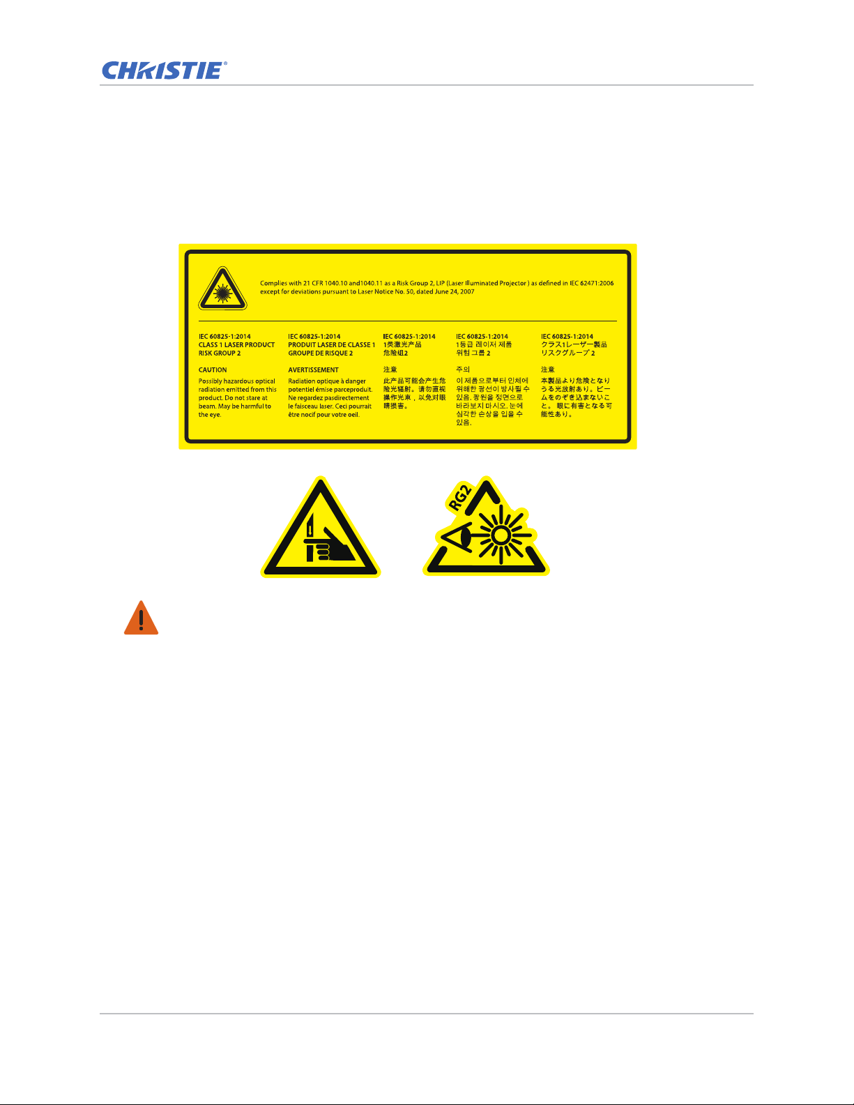
Laser safety warnings
This product is classified as CLASS 1 LASER PRODUCT - RISK GROUP 2 accordin g to IEC 60825-1 :
2014 complies with FDA regulations 21 CFR 1040.10 and 1040.11 as a Risk Group 2 , LIP ( Laser
Illuminated Projector) as defined in IEC 62471:2006 except for deviations pursuant to Laser Notice
No. 50, dated June 24, 2007.
Warning! Failure to comply with the following could result in death or serious injury.
• This projector has a built-in Class 4 laser module. Never attempt to disassemble or modify the
projector.
• Any operation or adjustment not specifically instructed in the User manual creates the risk of
hazardous laser radiation exposure.
• Do not open or disassemble the projecto r as this ma y cause damage or exposure to laser r adiation.
• Do not stare into beam when the projector is on. The bright light may result in permanent eye
damage.
• When turning on the projector, make sure no one within projection range is looking into the lens.
• Follow the control, adjustment, or operation procedures to avoid damage or injury from exposure
of laser radiation.
• The instructions for the assembly, operation, and maintenance include clear warnings concerning
precautions to avoid possible exposure to hazardous laser radiation.
GS Series 630-635 User Manual 8
020-001213-02 Rev. 1 (02-2018)
Page 9
Introduction
2
4
1
3
The product specified in this document is a high brightness, high-resolution video/graphics 1-chip
laser based projector. The projector is available in HD and WUXGA resolutions. The projector utilizes
Digital Light Processing (DLP
for fixed installation markets.
Projector components
Identify the main components of the projector.
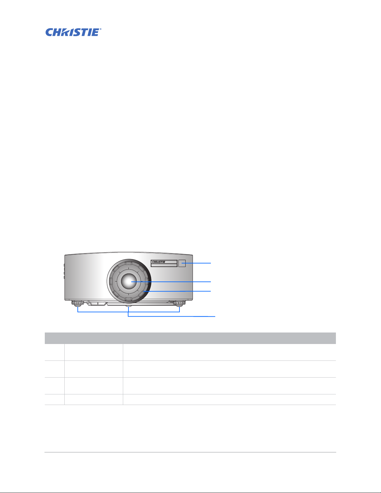
Front view
Identify the main components on the front of the projector.
®
) technology from Texas Instruments. It is primarily designed
ID Part name Description
1 Front IR sensors Receives signals from the IR remote keypad. Keep the signal path to the sensor
unobstructed for uninterrupted communication with the projector.
2 Projection lens Allows automated lens control and adjustment: vertical and horizontal offsets,
zoom, and focus.
3 Lens ring Protects the lens motors and mechanism. Remove in order to insert or remove the
lens.
4 Adjustable feet Raises or lowers the feet to level the projector.
GS Series 630-635 User Manual 9
020-001213-02 Rev. 1 (02-2018)
Page 10
Introduction
1
2
4
3
5
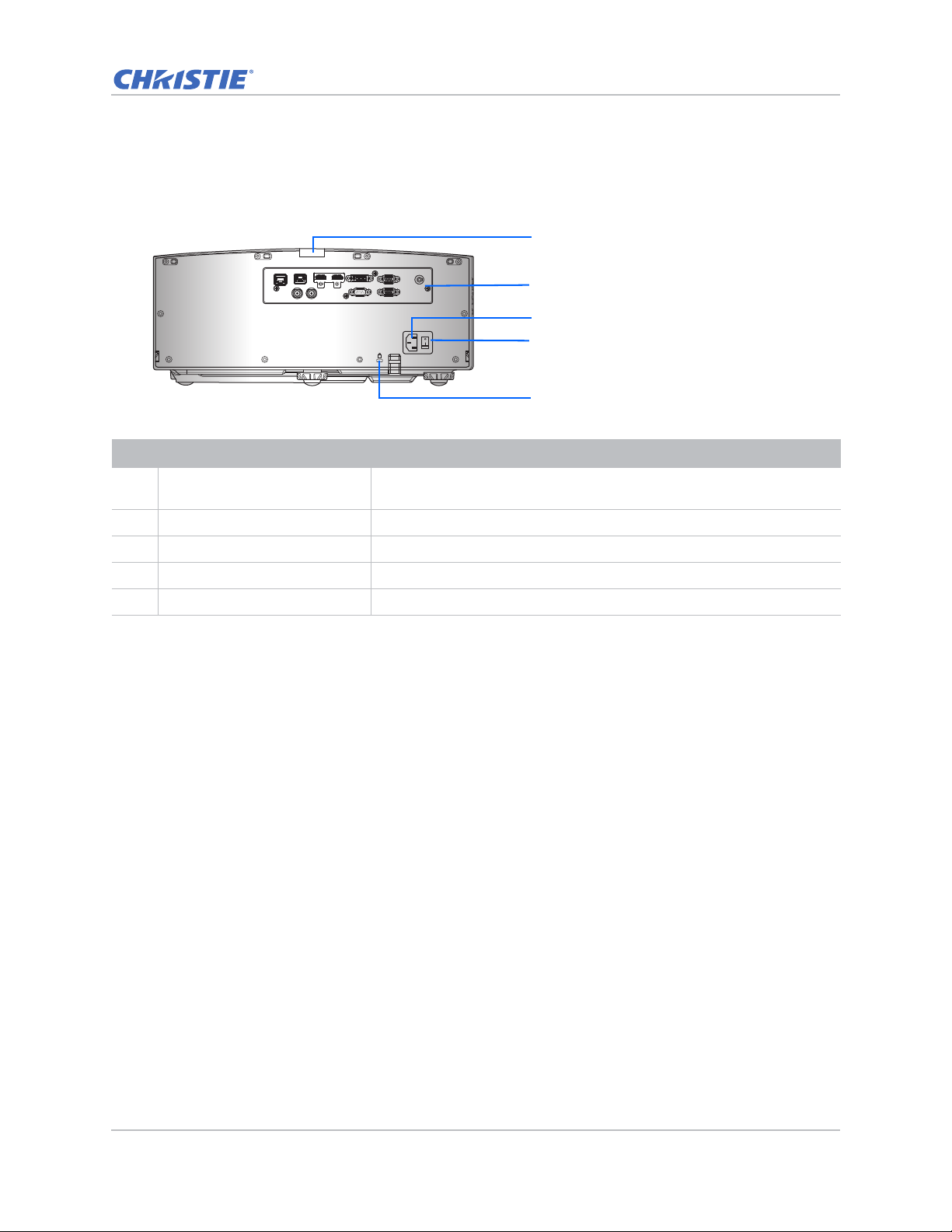
Rear view
Identify the main components on the rear of the projector.
VGA INDVI-DHDMI-2HDMI-1HDBaseTETHERNET
REMOTE
IN
3D
SYNC OUT3DSYNC IN
ID Part name Description
1 Rear IR sensor Receives signals from the IR remote keypad. Keep the signal path
2 Input/Output (I/O) panel Connects the projector to external devic es.
3 AC input Connects to the supplied power adapter (100-240V~).
VGA OUTRS-232
K
unobstructed for uninterrupted communication with the projector.
4 Power button Powers the projector on or off.
5 Kensington security slot Secures the projector to help prevent theft or unauthorized removal.
GS Series 630-635 User Manual 10
020-001213-02 Rev. 1 (02-2018)
Page 11
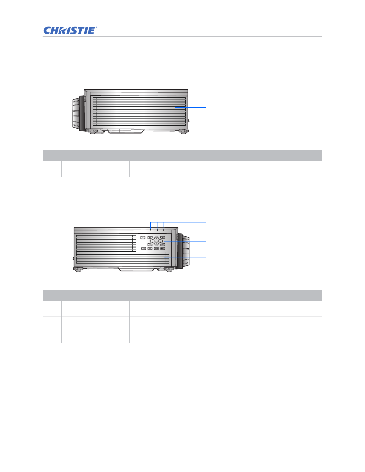
Left view
1
2
3
1
Identify the main components on the left side of the projector.
ID Part name Description
Introduction
1 Cooling air vents (intake) Provides cooling to the projector. Keep these vents unobstructed to prevent
the projector from overheating.
Right view
Identify the main component on the right side of the projector.
ID Part name Description
1 LED Status Indicators Displays the status of the projector. They are (from left to right): LIGHT,
STATUS, and PICTURE MUTE.
2 Built-in keypad Controls the projector.
3 Cooling air vents
(exhaust)
Provides cooling to the projector. Keep these vents unobstructed to prevent
the projector from overheating.
GS Series 630-635 User Manual 11
020-001213-02 Rev. 1 (02-2018)
Page 12
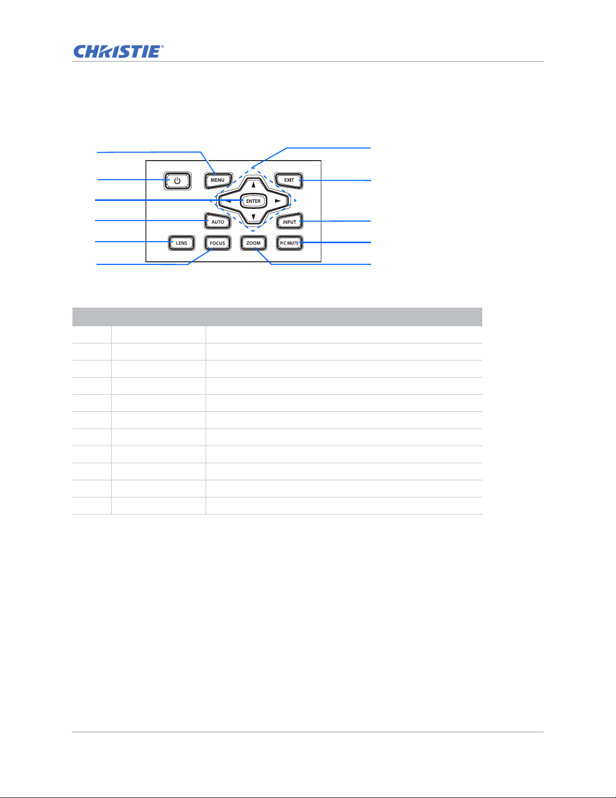
Built-in keypad
7
8
10
11
1
2
4
6
3
9
5
The built-in keypad controls the projector.
ID Part name Description
1 Menu Displays the menus.
2 Power Turns the projector on or off.
Introduction
3 Enter Confirms a selection.
4 Auto Automatically optimizes an image.
5 Lens Adjusts the lens vertical or horizontal offset setting.
6 Focus Adjusts the focus.
7 Arrow keys Adjusts a setting up or down, or navigate within a menu.
8 Exit Returns to the previous level or exits the menu s if at top level.
9 Input Selects an input for the main or PIP/PBP image.
10 Picture mute Displays or blanks the video image.
11 Zoom Adjusts the zoom.
GS Series 630-635 User Manual 12
020-001213-02 Rev. 1 (02-2018)
Page 13
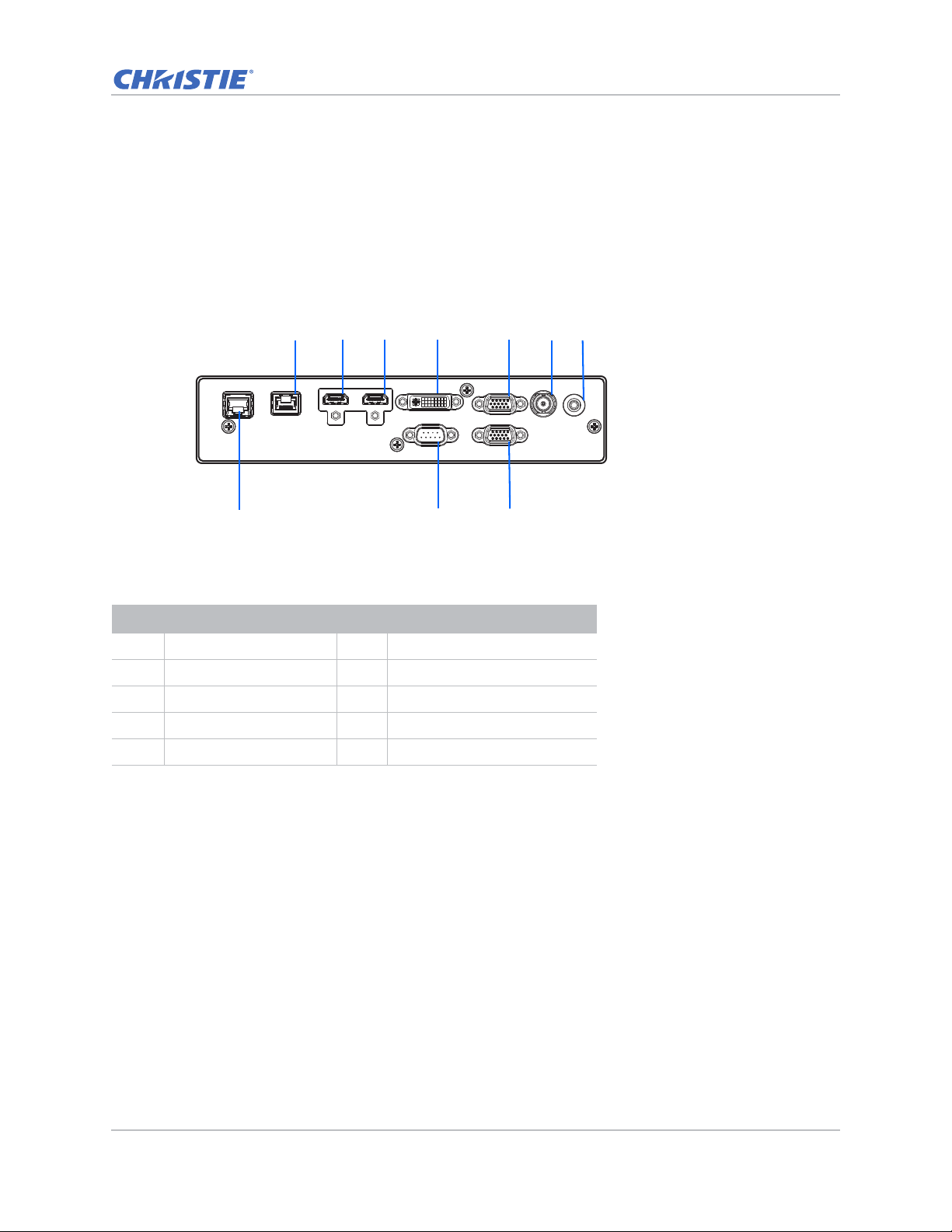
Input/Output (I/O) panel
REMOTE
IN
VGA INDVI-DHDMI-2HDMI-1HDBaseTETHERNET
VGA OUTRS-232
3D
SYNC OUT
123 4 56
8
9 10
7
Identify the components of the Input/Output (I/O) panel.
DWU630-GS/DHD630-GS Series
Introduction
ID Connector name ID Connector name
1HDBaseT 63D SYNC OUT
2HDMI-1 7REMOTE IN
3 HDMI-2 8 ETHERNET (LAN)
4 DVI-D 9 RS-232
5 VGA IN 10 VGA OUT
GS Series 630-635 User Manual 13
020-001213-02 Rev. 1 (02-2018)
Page 14
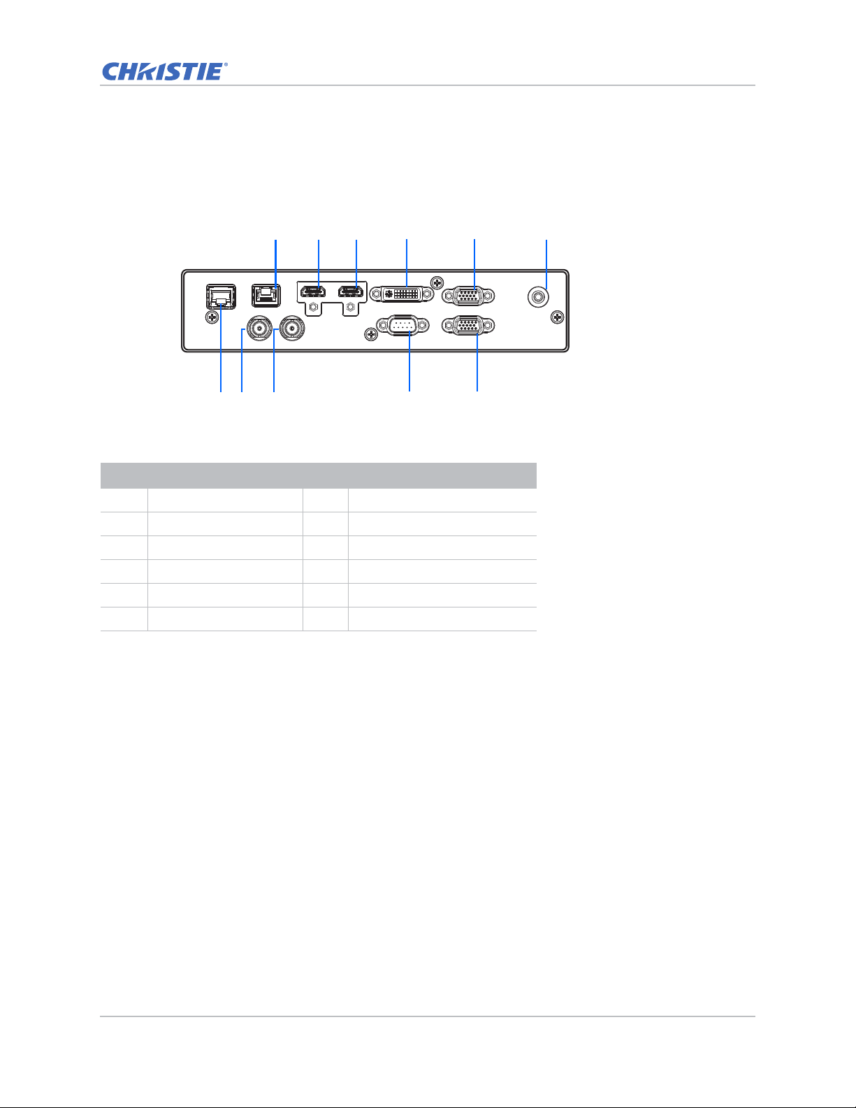
DWU635-GS/DHD635-GS Series
REMOTE
IN
VGA INDVI-DHDMI-2HDMI-1HDBaseTETHERNET
VGA OUTRS-232
3D
SYNC OUT
3D
SYNC IN
1
9
23 4 5 6
7
8
10
11
ID Connector name ID Connector name
Introduction
1 HDBaseT 7 ETHERNET (LAN)
2HDMI-1 83D SYNC IN
3HDMI-2 93D SYNC OUT
4 DVI-D 10 RS-232
5 VGA IN 11 VGA OUT
6REMOTE IN
GS Series 630-635 User Manual 14
020-001213-02 Rev. 1 (02-2018)
Page 15
Introduction
16
17
18
19
20
21
22
24
25
26
27
28
29
1
2
3
4
5
6
7
8
9
10
11
12
13
14
15
23
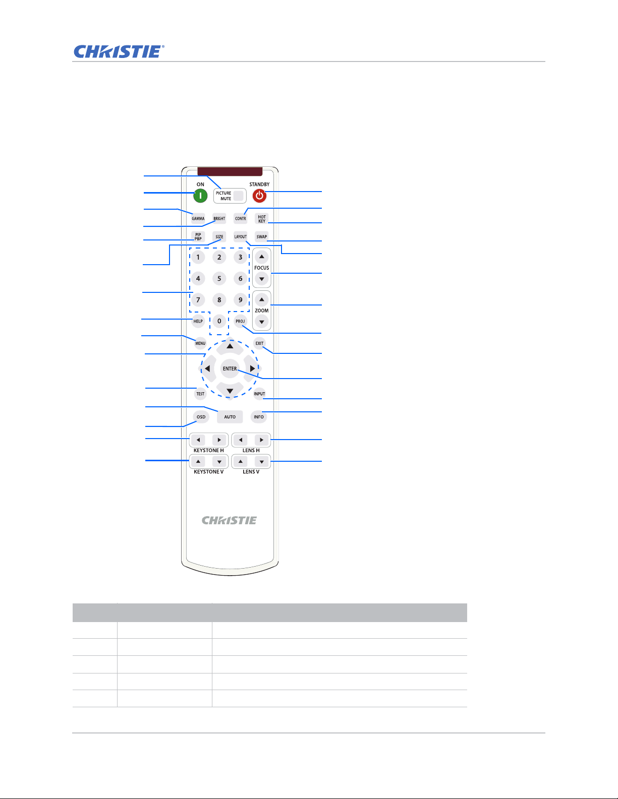
IR remote keypad
The IR remote keypad communicates with the projector by way of wireless communications.
Use a cable length of 20 m or less. If the length of cable exceeds 20 m, the IR remote keypad may
not work correctly.
ID Button Description
1 PICTURE MUTE Displays or blanks the video image.
2 ON Turns the projector on.
3 GAMMA Adjusts the mid-range levels.
4 BRIGHT Adjusts the amount of light in the image.
5 PIP/PBP Turns PIP/PBP on or off.
GS Series 630-635 User Manual 15
020-001213-02 Rev. 1 (02-2018)
Page 16

ID Button Description
6 SIZE Adjusts the PIP/PBP size.
7 Number Keys Enters a number, such as a channel, value, and so on. The
on-screen display indicates if a function is not supported.
8 HELP Displays the instructions for source connection.
9 MENU Displays the menus.
10 Arrow Keys Adjusts a setting up or down to navigate within a menu.
11 Test Displays a test pattern.
12 AUTO Automatically optimizes an image.
13 OSD Uses to hide or shows on-screen display (OSD) menus.
14 KEYSTONE H Adjusts the horizontal keystone.
15 KEYSTONE V Adjusts the vertical keystone.
16 STANDBY Turns the projector off.
17 CONTR Adjusts the difference between dark and light.
18 HOT KEY Selects your preset key quickly.
19 SWAP Swaps the main and PIP/PBP images.
20 LAYOUT Adjusts the PIP/PBP layout.
Introduction
21 FOCUS Adjusts the focus to improve image clarity as required.
22 ZOOM Adjusts the zoom to achieve a required image size.
23 PROJ Changes the IR remote keypad ID.
• To assign an ID, press Proj + <1 to 9>.
• To return to the universal IR remote ID, press Proj + 0.
24 EXIT Returns to previous level or exit menus if at top level.
25 ENTER Selects a highlighted menu item, or changes or accepts a
value.
26 INPUT Selects an input for the main or PIP/PBP image.
27 INFO Displays the source image information.
28 LENS H Adjusts the position of the image horizontally.
29 LENS V Adjusts the position of the image vertically.
GS Series 630-635 User Manual 16
020-001213-02 Rev. 1 (02-2018)
Page 17
LED status indicators
LEDs are defined below.
Light LED
Identify the laser diode state colors and meaning.
LED status Projector state
Red (flashing) Projector has lost over 60% initial luminance.
Orange (solid) Laser diode time has expired.
Green (solid) Laser diode is on and operating correctly.
Off Laser diode is off.
Status LED
Identify the LED state colors and meaning.
Introduction
LED status Projector state
Off AC power is off (without AC plugged in).
Off, but keypad LED is on AC has been applied, projector is in standby mode.
NOTE: Status LED cannot be flashing red, as this is reserved for an error condition.
Status LED is off but keypad LED will indicate Standby Mode.
Green (solid) Projector is powered up and operating normally.
Green (flashing) Projector communications.
Orange (flashing) Projector is in cool down mode or startup mode.
Green (flashing) / Orange
(solid)
Red (solid) Over-temperature.
Red (flashing) Fan failure.
Projector is in flash update state.
Picture Mute LED
Identify the picture mute LED state colors and meaning.
LED status Projector state
Green (solid) Light is on and an image is displayed.
Orange (solid) Light is on and the image is blank.
GS Series 630-635 User Manual 17
020-001213-02 Rev. 1 (02-2018)
Page 18
Installation
3 4 5 6
7
2
Desktop Laptop
Monitor
Video
Equipment
1
Learn how to install, connect, and optimize the projector display.
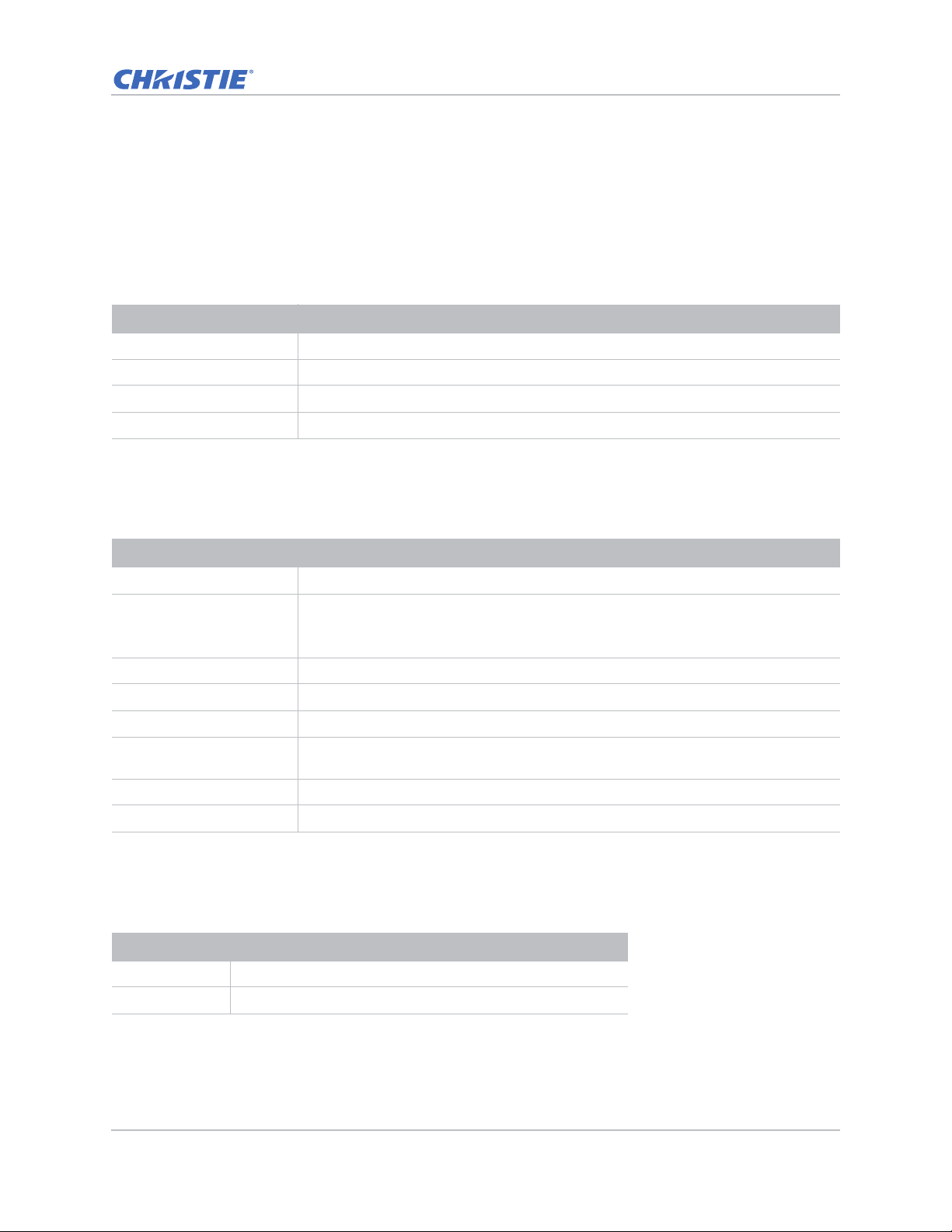
Connecting to a computer
Learn what cables/connectors that may be used to connect to various devices.
DWU630-GS/DHD630-GS Series
ID Connector name ID Connector name ID Connector name
1 HDMI cable 4 RS-232 cable 7 Power cord
2 DVI-D cable 5 3D sync out cable
3 VGA in cable 6 VGA out cable
GS Series 630-635 User Manual 18
020-001213-02 Rev. 1 (02-2018)
3D
VGA INDVI-DHDMI-2HDMI-1HDBaseTETHERNET
REMOTE
SYNC OUT
IN
VGA OUTRS-232
Page 19
• Due to the difference in applications for each country, the accesso r ies required in some regions
1 3 4 5 6 7
8
2
Desktop Laptop
Monitor
Video
Equipment
may differ from those shown.
• This diagram is for illustrative purposes only, and does not indicate that these accessories are
supplied with the projector.
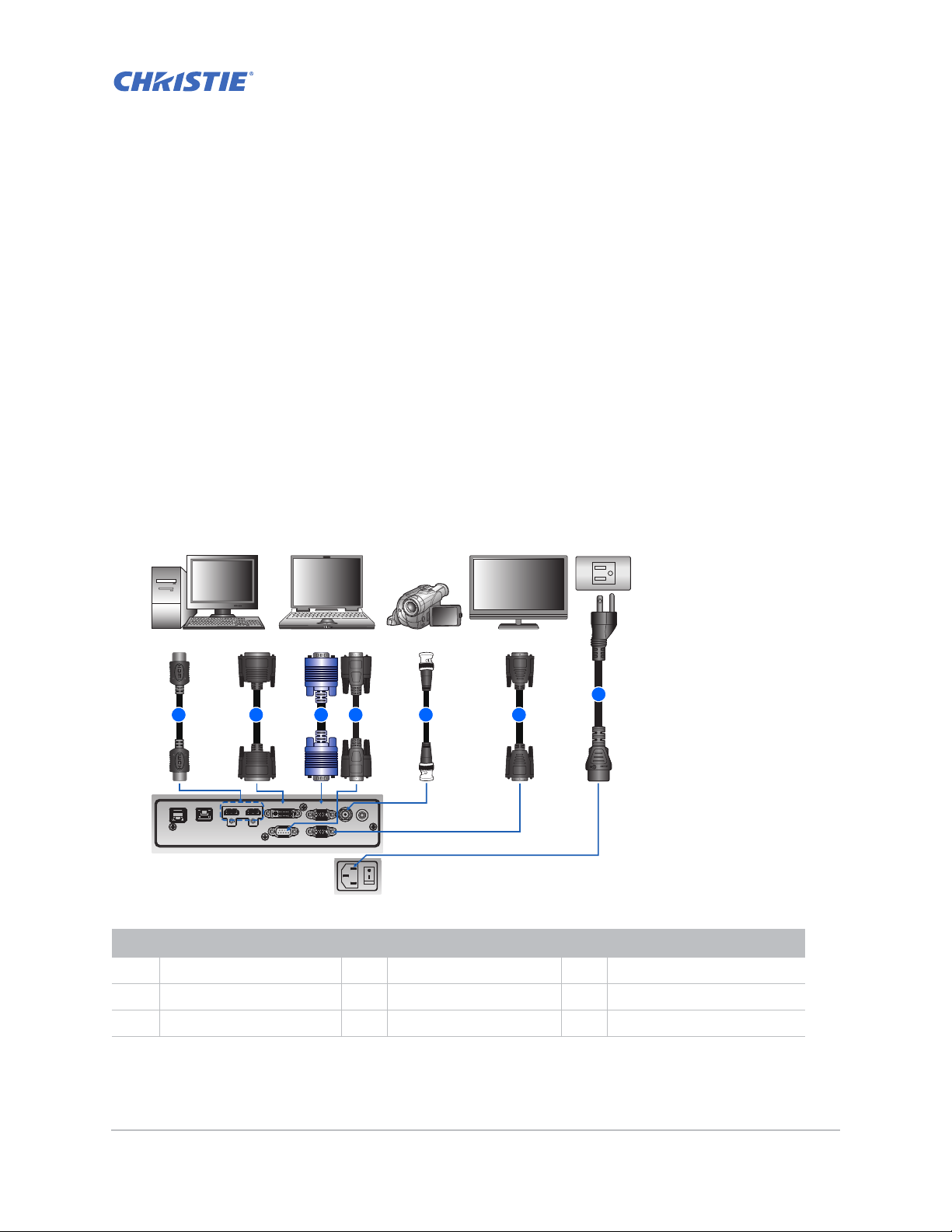
DWU635-GS/DHD635-GS Series
Installation
VGA INDVI-DHDMI-2HDMI-1HDBaseTETHERNET
REMOTE
IN
3D
SYNC OUT3DSYNC IN
VGA OUTRS-232
ID Connector name ID Connector name ID Connector name
1 3D sync out cable 4 DVI-D cable 7 VGA out cable
2 3D sync in cable 5 VGA in cable 8 Power cord
3 HDMI cable 6 RS-232 cable
• Due to the difference in applications for each country, the accesso r ies required in some regions
may differ from those shown.
• This diagram is for illustrative purposes only, and does not indicate that these accessories are
supplied with the projector.
GS Series 630-635 User Manual 19
020-001213-02 Rev. 1 (02-2018)
Page 20
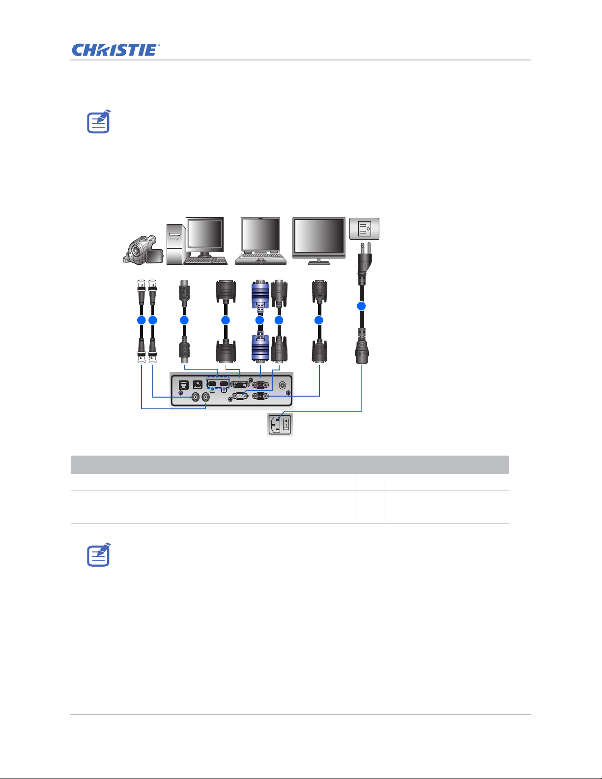
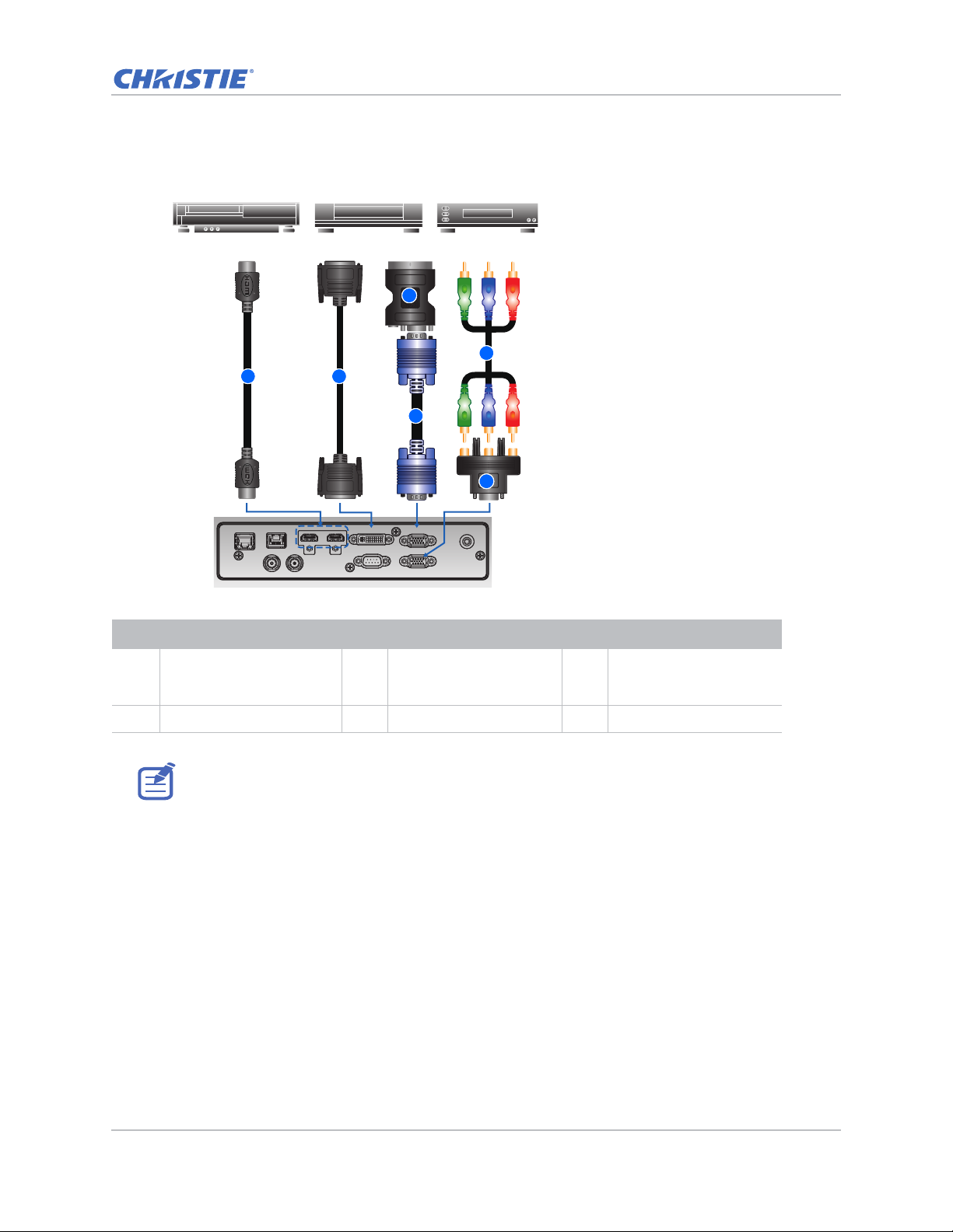
Connecting to video equipment
REMOTE
IN
VGA INDVI-DHDMI-2HDMI-1HDBaseTETHERNET
VGA OUTRS-232
3D
SYNC OUT
1 2
3
4
Component video output equipment DVD player Video cassette recorder
6
5
Learn what cable/connectors may be used to connect to various devices.
DWU630-GS/DHD630-GS Series
Installation
ID Connector name ID Connector name ID Connector name
1 HDMI cable 3 VGA in cable 5 15-pin to 3 RCA
2 DVI-D cable 4 VGA to Component 6 3 RCA Component cable
• Due to the difference in applications for each country, the accesso r ies required in some regions
GS Series 630-635 User Manual 20
020-001213-02 Rev. 1 (02-2018)
may differ from those shown.
• This diagram is for illustrative purposes only, and does not indicate that these accessories are
supplied with the projector.
Component/HDTV
Adapter
Page 21
DWU635-GS/DHD635-GS Series
1 2
3
4
Component video output equipment DVD player Video cassette recorder
6
5
Installation
3D
3D
SYNC OUT
SYNC IN
ID Connector name ID Connector name ID Connector name
1 HDMI cable 3 VGA in cable 5 15-pin to 3 RCA
2 DVI-D cable 4 VGA to Component 6 3 RCA Component cable
• Due to the difference in applications for each country, the accesso r ies required in some regions
may differ from those shown.
• This diagram is for illustrative purposes only, and does not indicate that these accessories are
supplied with the projector.
VGA INDVI-DHDMI-2HDMI-1HDBaseTETHERNET
VGA OUTRS-232
REMOTE
IN
Component/HDTV
Adapter
GS Series 630-635 User Manual 21
020-001213-02 Rev. 1 (02-2018)
Page 22
Installation
1
1
1
1
1
2
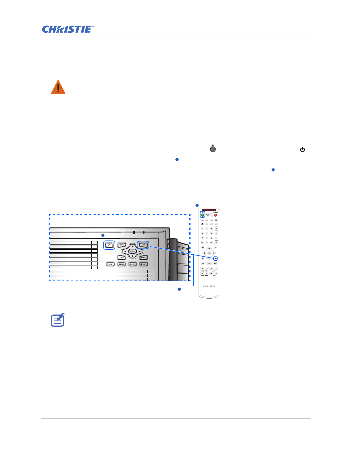
Turning the projector on
The projector cables must be securely connected before turning the power on.
Warning! Failure to comply with the following could result in death or serious injury.
• Do not look into the projector lens when the laser is on. The bright light may result in permanent
eye damage
1. Connect the projector power cables to AC power.
The Power button on the keypad is illuminated when the power cables are connected.
2. Ensure the lens has been installed in the projector.
3. Ensure that no one or no objects are in the beam path before turning on the projector.
4. To turn on the projector, on the IR remote keypad press or on the built-in keypad press .
The status LED is orange with a long blink.
5. To select an input source and turn it on, on the IR remote keypad select Input.
Available input sources are VGA, HDMI, DVI, and HDBaseT.
The projector detects the source you selected and displays the image.
1
2
1
Power on
1
Power on
Input Key
The first time the projector is used, select the preferred language from the Main Menu after the
startup screen is displayed.
GS Series 630-635 User Manual 22
020-001213-02 Rev. 1 (02-2018)
Page 23
Installation
Turning the projector off
Power off the projector in preparation for inspection or maintenance.
1. To turn the projector off, on the IR remote keypad or built-in keypad press .
A warning message appears on the displayed image.
2. To confirm your selection, press again.
If you do not press again, the warning message disappears after three seconds and the
projector remains on.
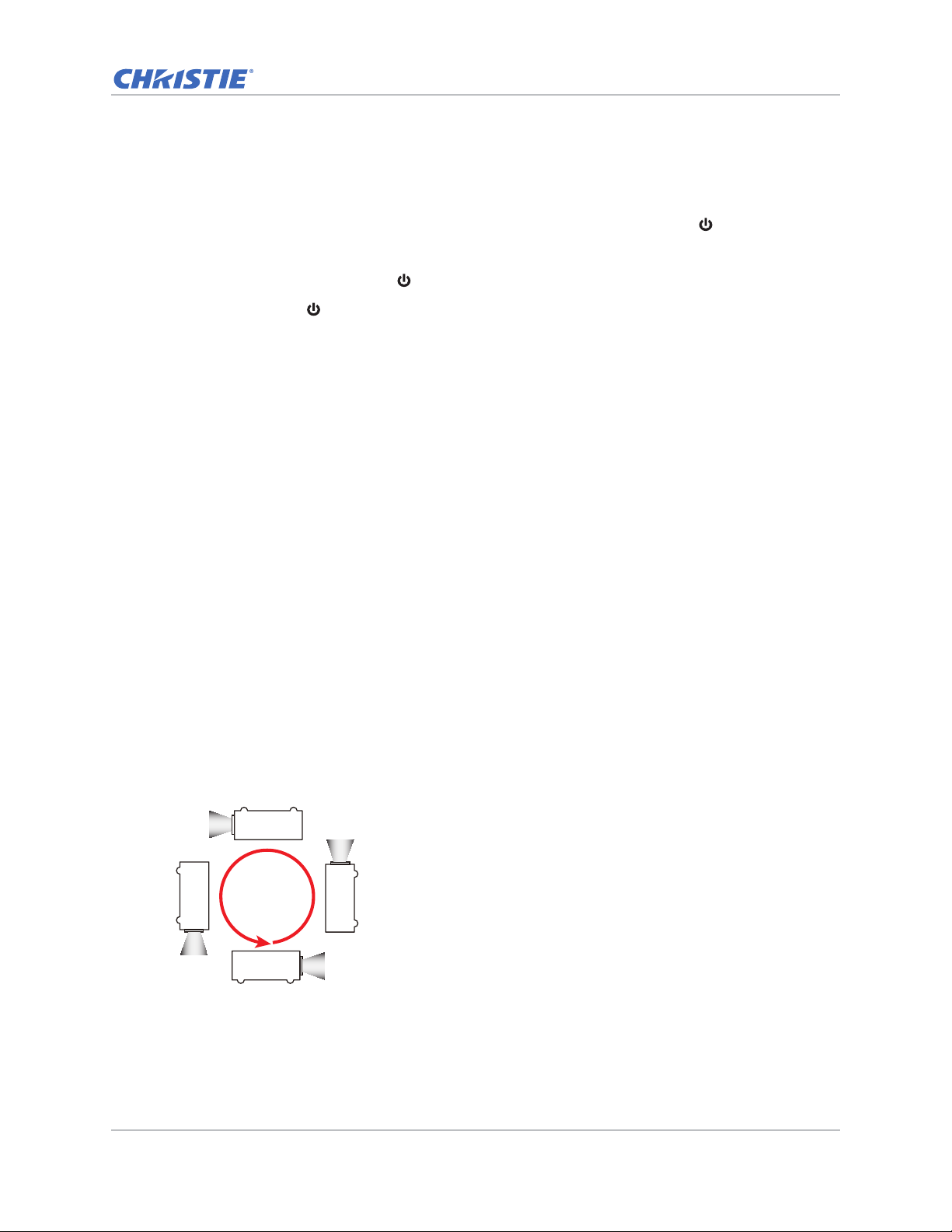
Adjusting the projector position
When you select a position for the projector, consider the size and shape of your screen, the
location of your power outlets, and the distance between the projector and the rest of your
equipment. Follow these general guidelines:
• Position the projector on a flat surface at a right angle to the screen. The projector (with the
standard lens) must be at least 3 feet (0.9 m) from the projection screen.
• Position the projector to the required distance from the screen. The distance from the lens of
the projector to the screen, the zoom setting, and the video format determine the size of the
projected image.
• Determine the lens throw ratio:
• Lens 1.22~1.53 (WU/HD)
• Lens 0.95~1.22 (WU/HD)
• Lens 1.52~2.89 (WU/HD)
• Lens 0.75~0.95 (WU/HD)
• Lens 2.90~5.50 (WU/HD)
• 360 degree operation (along the widest axis)
360°
GS Series 630-635 User Manual 23
020-001213-02 Rev. 1 (02-2018)
Page 24
Installation
Lens center
0 %0 %
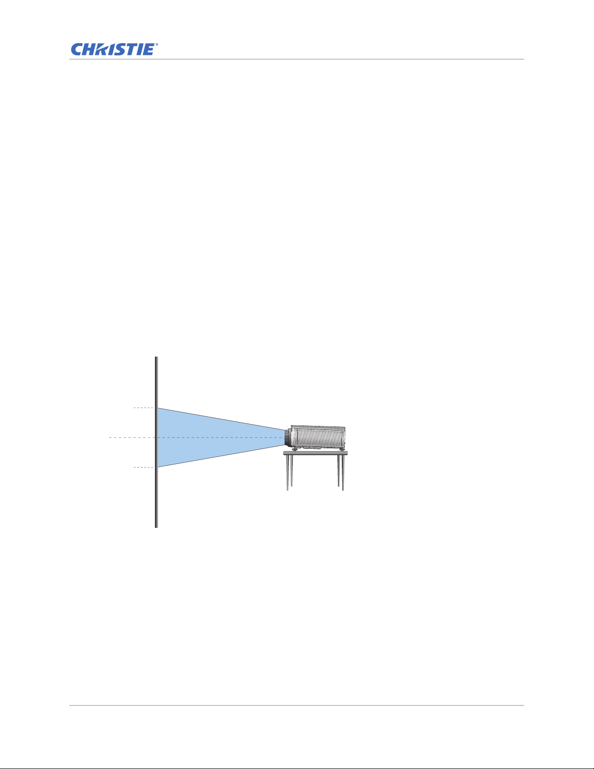
Calculating the lens offset
Adjust the offset to align the image on the screen with half image size.
• The vertical image offset (shift) ranges for the projector are +/-100% (WUXGA) and +/-120%
(HD).
• The horizontal image offset (shift) range for the projector are +/-30% (HD/WUXGA).
• The method for calculating lens offset complies with industry standards. For example for
vertical lens offset:
• At 0% offset (or on axis), the center of the image is on the lens center, so half of the
image appears above and half appears below the lens center.
• At +100% offset, the entire image appears above the lens center.
• The percentage (%) offset is calculated as the ratio of the number of pixels shifted up or
down to half image size.
WUXGA projectors
The following show vertical and horizontal image offsets for the WUXGA projectors:
• Vertical image offset: 0%
GS Series 630-635 User Manual 24
020-001213-02 Rev. 1 (02-2018)
Page 25
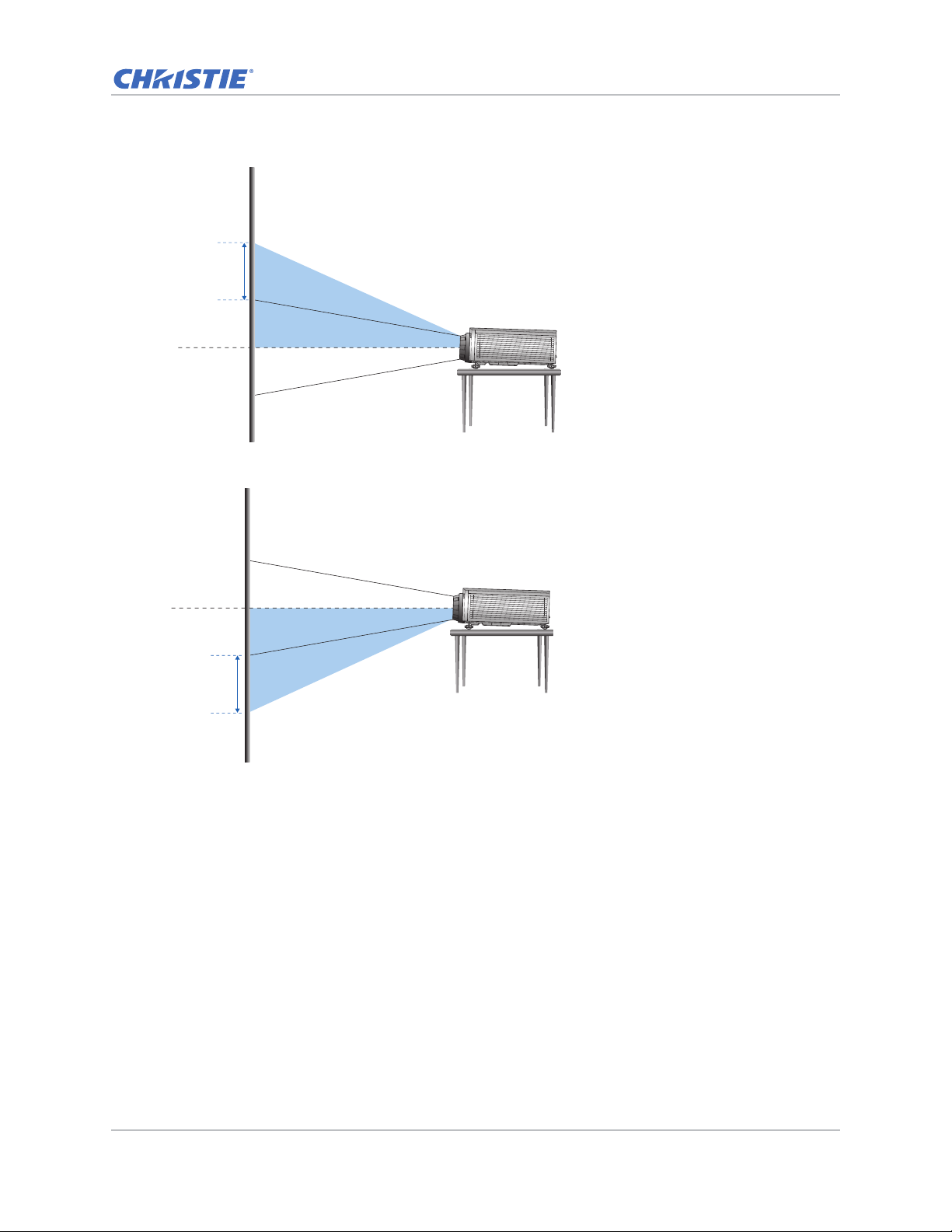
• Vertical image offset: +100%
Lens center
+100%
Lens center
+100%
• Vertical image offset: -100%
Installation
GS Series 630-635 User Manual 25
020-001213-02 Rev. 1 (02-2018)
Page 26
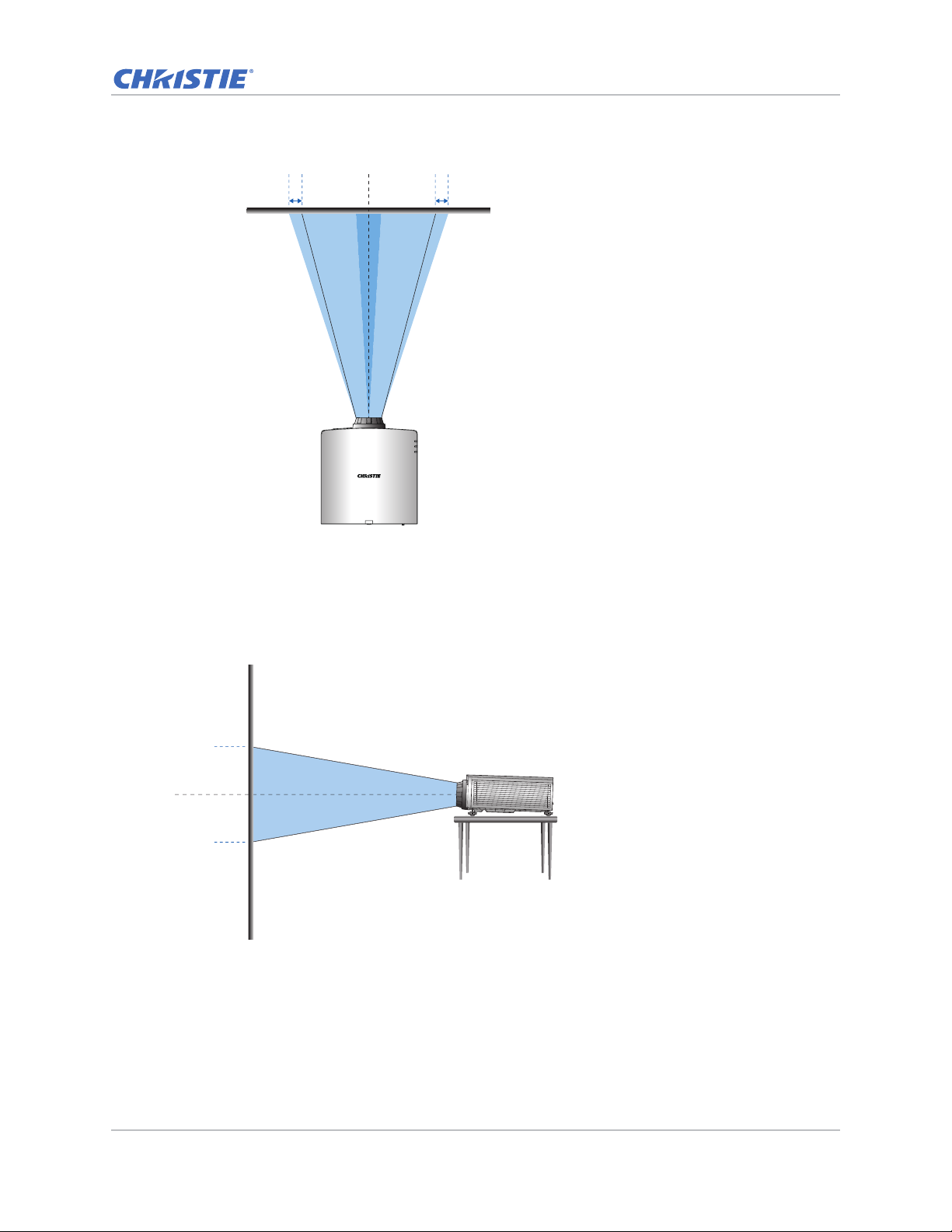
• Horizontal image offset: +/-30%
Lens center
-30% 0% +30%0%
Lens center
0 %0 %
Installation
HD Projectors
The following show vertical and horizontal image offset for HD projectors:
• Vertical image offset: 0%
GS Series 630-635 User Manual 26
020-001213-02 Rev. 1 (02-2018)
Page 27
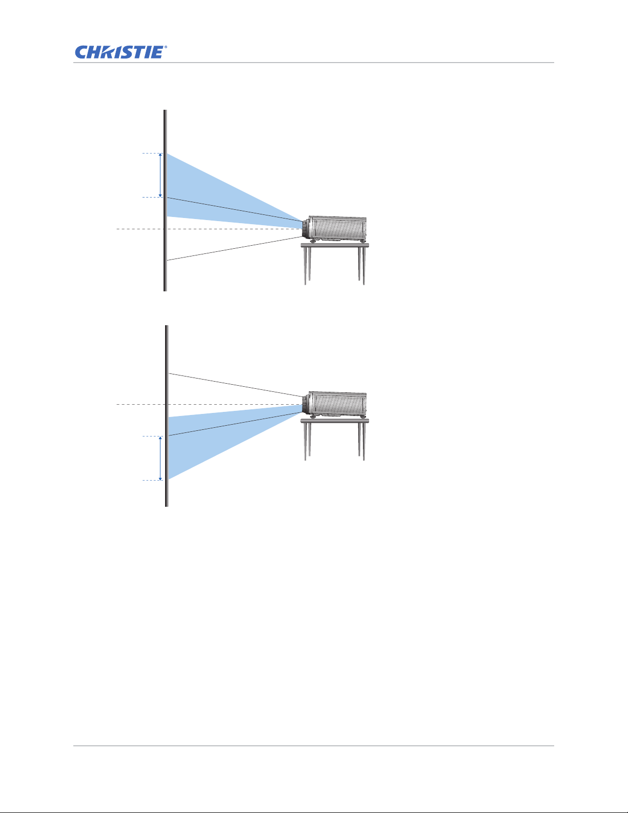
• Vertical image offset: +120%
Lens center
+120%
Lens center
-120%
• Vertical image offset: -120%
Installation
GS Series 630-635 User Manual 27
020-001213-02 Rev. 1 (02-2018)
Page 28
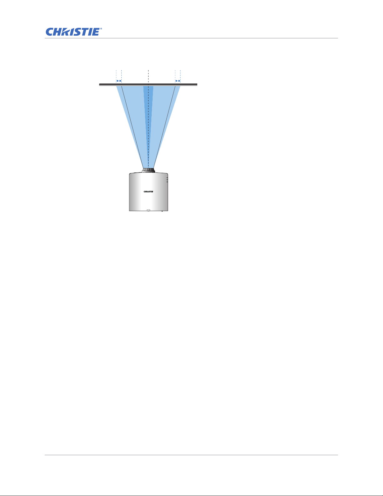
• Horizontal image offset: +/-30%
Lens center
-30% 0% +30%0%
Installation
GS Series 630-635 User Manual 28
020-001213-02 Rev. 1 (02-2018)
Page 29
Installation
B
A
B
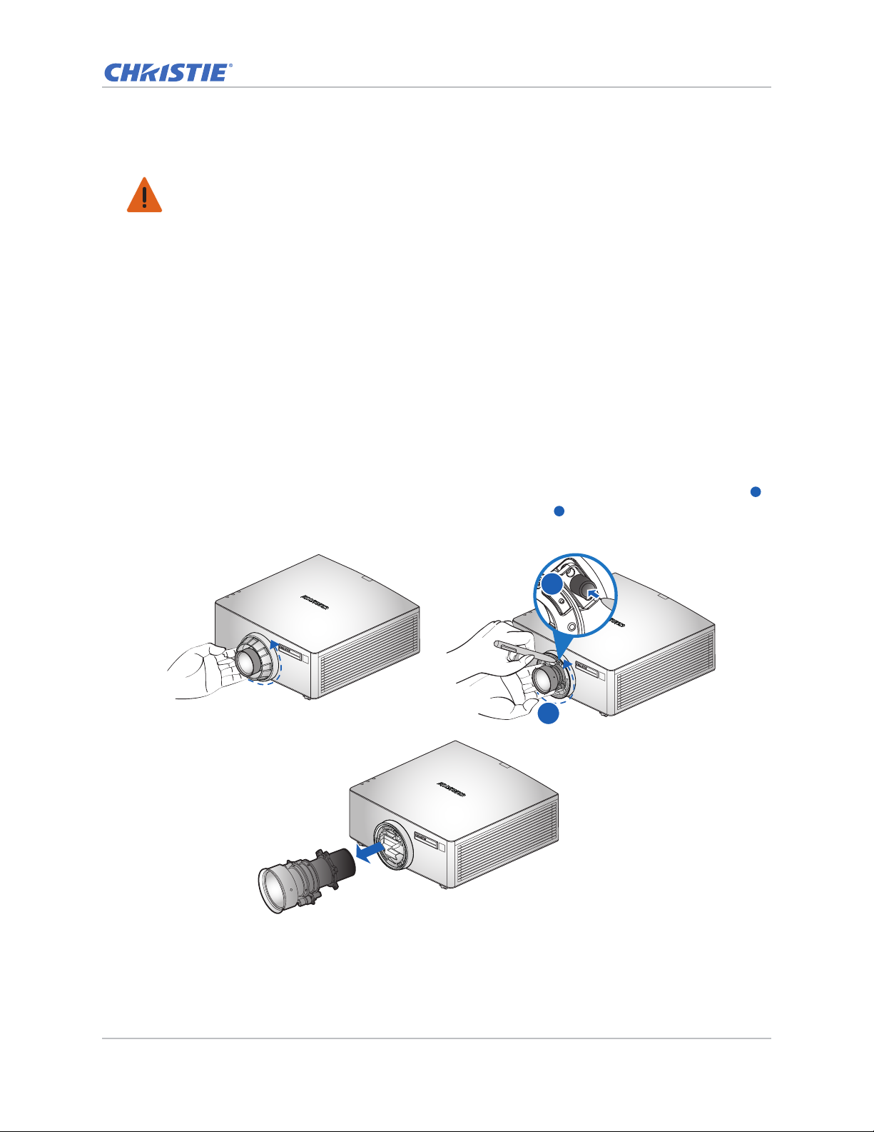
Removing and installing the lens
Warning! Failure to comply with the following could result in death or serious injury.
• Turn off the projector and remove the power cord, before installing or replacing a lens.
When handling the projector after lens installation, make sure the front lens cap is placed on the
lens to protect the lens surface from potential damage. When carrying or moving the projector, do
not handle by the lens. This may damage the lens, the chassis, or other mechanical parts within the
projector.
1. Center the lens. Ensure the lens is at or near its center position. Attempting to remove the lens
with a large offset may cause damage to the lens assembly.
Center the lens while the projector is switched on by pressing the Lens Horizontal or Lens
Vertical button and then pressing Enter.
2. Turn off the projector.
3. Allow the projector to cool down into standby mode before replacing the lens.
4. After the projector has cooled down and prior to replacing the lens, remove the power cord.
5. To remove the lens, remove the lens ring cover first. Then press the Lens Release button
with a tool and rotate the lens counterclockwise by a quarter to release the lock.
A
Remove the lens through the front of the projector.
6. To install the new lens, fully insert the lens assembly straight into the lens mount without
turning. Rotate the lens cap clockwise to lock the lens in place.
GS Series 630-635 User Manual 29
020-001213-02 Rev. 1 (02-2018)
Page 30
Installation
Guide Pin
Guide Hole
Hold and Press Here
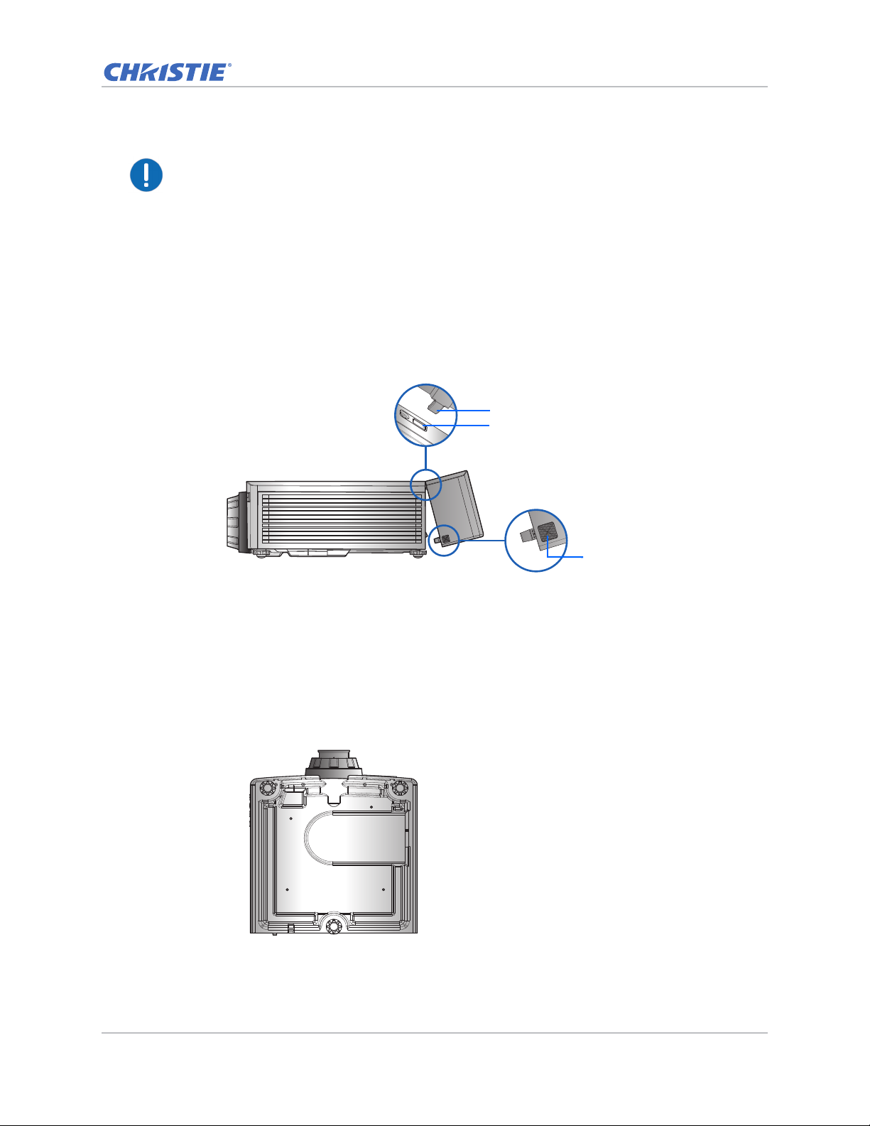
Notice. For ultra short throw lens installation information, refer to the Ultra short throw lens
installation instruction sheet (P/N: 020-102569-XX).
Installing the cable cover
1. Rotate the cable cover and insert the two guide pins into the guide holes.
2. Press and hold both lower corners of the cable cover while inserting the sheet clips into the
projector casing.
Installing the ceiling mount
Mount the projector with a Christie-approved mount, using the four mounting points on the
underside of the projector.
See List of components on page 77.
1. Refer to the installation instructions and safety guidelines provided in the kit.
See List of components on page 77.
GS Series 630-635 User Manual 30
020-001213-02 Rev. 1 (02-2018)
Page 31
Installation
11
22
33
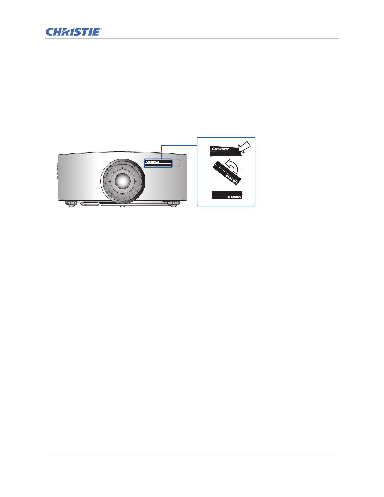
Rotating the Christie badge
The Christie magnetic badge on the front panel of the projector can be rotated for inverted
installation.
1. Push on the edge of the badge to release it from its slot on the front panel.
2. Rotate the badge 180 degrees.
3. Push the badge back into its slot on the front panel. Make sure the badge is properly seated
inside the slot.
GS Series 630-635 User Manual 31
020-001213-02 Rev. 1 (02-2018)
Page 32

Operation
The projector has multilingual on-screen display (OSD) menus so you can make image adjustments
and change a variety of settings.
Most of the projector controls are accessed from within the projector menu system. Several groups of
related functions are selectable from the Main menu as shown below.
1. To display the Main menu, on the IR remote keypad or on the built-in keypad on the right side
of the projector, press MENU.
2. To navigate within the menu and adjust a setting up or down, use the arrow keys.
3. To select a highlighted menu item or use it to change or accept a value, press ENTER.
You can then select the next item that you want to adjust in the menu and adjust it.
4. To exit menus if at top level, press EXIT.
GS Series 630-635 User Manual 32
020-001213-02 Rev. 1 (02-2018)
Page 33
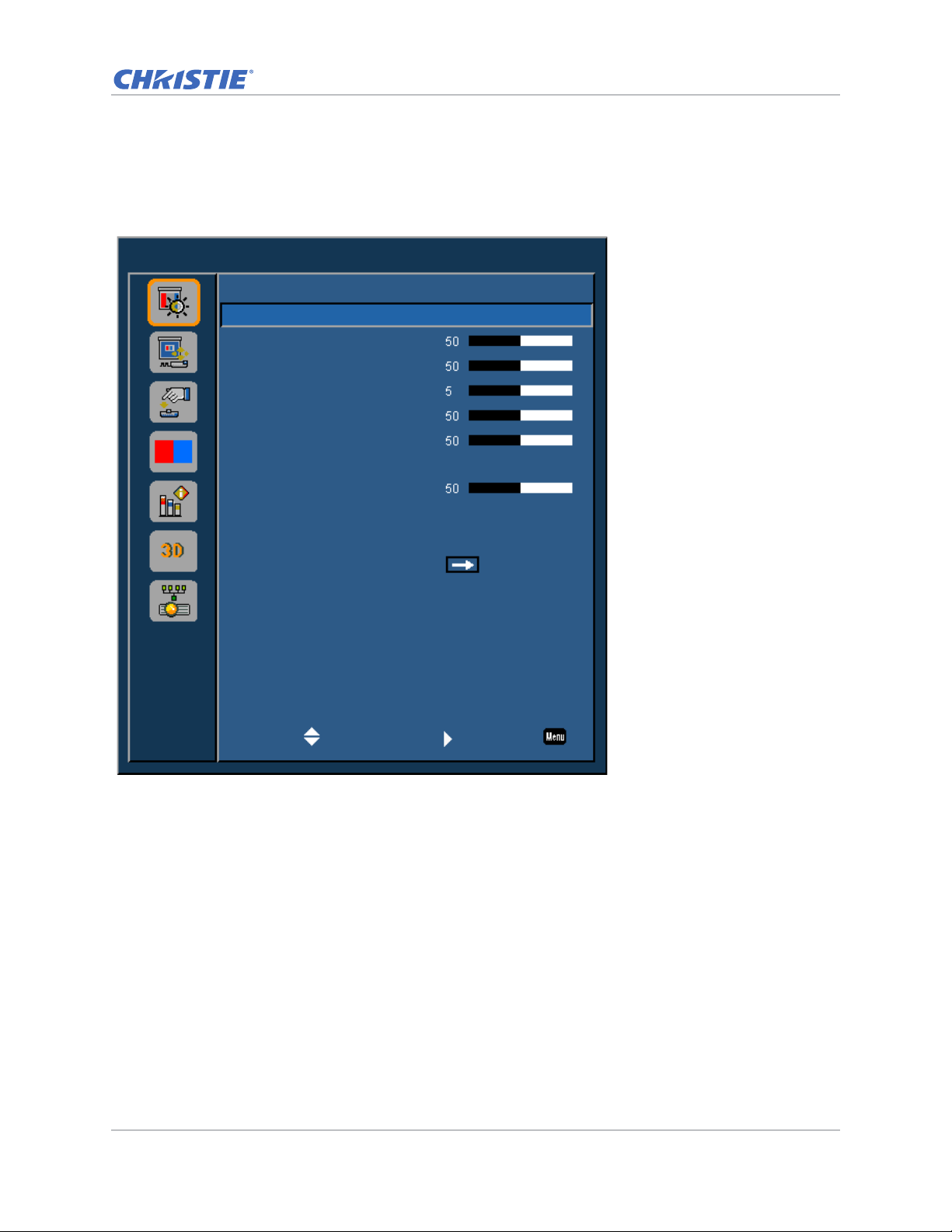
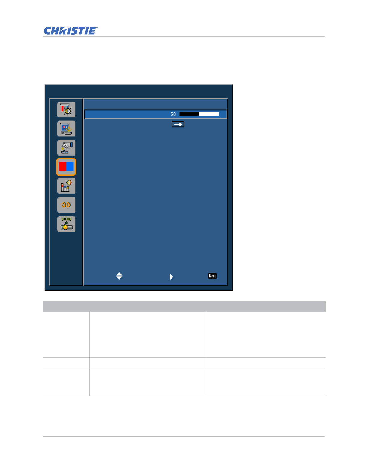
Picture menu
Picture
Picture Settings
Wall Color
Brightness
Contrast
Sharpness
Color
Tint
Gamma
White Peaking
Color Temp
Color Wheel Speed
HSG Adjustment
Contrast Enhancement
Color Space
Presentation
White
Video
Bright
3x
Off
Auto
Select Enter Exit
The Picture menu sets the picture settings, wall color, and other settings for images.
Operation
GS Series 630-635 User Manual 33
020-001213-02 Rev. 1 (02-2018)
Page 34

Menu item Description Options
Operation
Picture Settings Optimizes the projector for displaying images
under certain conditions. It affects the following:
• Gamma
• Sharpness
• White Peaking
• Overscan
• Brightness
• Bright
• Presentation
• Film
• REC709
• Blending
• DICOM SIM.
• User
• Contrast
• Color
• Tint
• Red Gain
• Green Gain
• Blue Gain
• Red Offset
• Green Offset
• Blue Offset
Wall Color Sets the wall color so that the projector can
enhance the color performance customized for
the specific wall.
• White
• Gray 130
Brightness Adjusts the intensity of the image. 0-100
Contrast Adjusts the degree of difference between the
0-100
lightest and darkest parts of the image and
changes the amount of black and white in the
image.
Sharpness Adjusts the edge clarity of the image. 0-10
Color Adjusts a video image from black and white to
0-100
fully saturated color. (Video sources only).
Tint Adjusts the red-green color balance in the image
0-100
of NTSC video images. (NTSC video sources
only).
Gamma Adjusts the mid-range levels. • Video
• Film
• Bright
• CRT
• DICOM
White Peaking Increases the brightness of whites near 100%. 0-100
Color Te mp Changes the intensity of the colors. Select a
listed relative warmth value.
• Warm
• Bright
• Cool
GS Series 630-635 User Manual 34
020-001213-02 Rev. 1 (02-2018)
Page 35

Menu item Description Options
Operation
Color Wheel
Speed
Selects the color wheel speed from 2x or 3x. The
color wheel speed defines the delay between the
color wheel and the DMD. The hi gher th e spee d,
the less rainbow effect on the screen.
HSG
Adjustment
Contrast
Enhancement
For more information on HSG adjustment, see
HSG Adjustment on page 37.
Enables or disables the contrast enhancement
function. Enable this function to raise the
contrast ratio.
Color Space Selects a color space specifically tuned fo r the
input signal. Only useful for analog signals and
certain digital sources.
• 2x
• 3x
• Red
• Green
• Blue
• Cyan
• Magenta
• Yellow
• White Gain
• Off
• Dynamic Black—Auto adjusts the contrast
ratio for video contents.
• Real Black—Reduces the black level for
dark images to raise the contrast ratio.
• Auto
• RGB(0~255)
• RGB(16~235)
• YUV
GS Series 630-635 User Manual 35
020-001213-02 Rev. 1 (02-2018)
Page 36
Operation
HSG Adjustment
Hue, Saturation, and Gain (HSG) software controls the color regions R, G, B, C, M, Y, and W
independently.
1. Select Picture > HSG Adjustment.
Hue
Note the following about adjusting hue:
• Adjust the hue independently for each color (R,G,B,C,M, and Y).
• White does not have a hue input.
• A negative hue input provides a clockwise rotation of the color's hue.
• A positive hue input provides a counter-clockwise rotation of the color's hue.
• A zero input does not change the hue of the color.
Saturation
Note the following about adjusting saturation:
• The saturation can be adjusted independently for each color (R,G,B,C,M, and Y).
• A saturation level of 0 removes all color from that region.
• A saturation level of 254 sets the color region to have maximum color.
GS Series 630-635 User Manual 36
020-001213-02 Rev. 1 (02-2018)
Page 37
• A saturation level of 127 does not change the saturation.
Operation
Gain
Note the following about adjusting gain:
• The gain can be adjusted independently for each color (R,G,B,C,M,Y, and W).
• The range of input is 0 to 254.
• The gain changes the intensity level of the respective color.
• A gain level of 127 disables the HSG controls for that color.
• A gain level less than 127 darkens the respective color.
• A gain level of 254 sets the color region to have maximum gain; however, clipping occurs on
the signal.
• A gain of 127 is the nominal setting.
• White provides three gain level controls, one each for the R,G,B component of white.
GS Series 630-635 User Manual 37
020-001213-02 Rev. 1 (02-2018)
Page 38
Operation
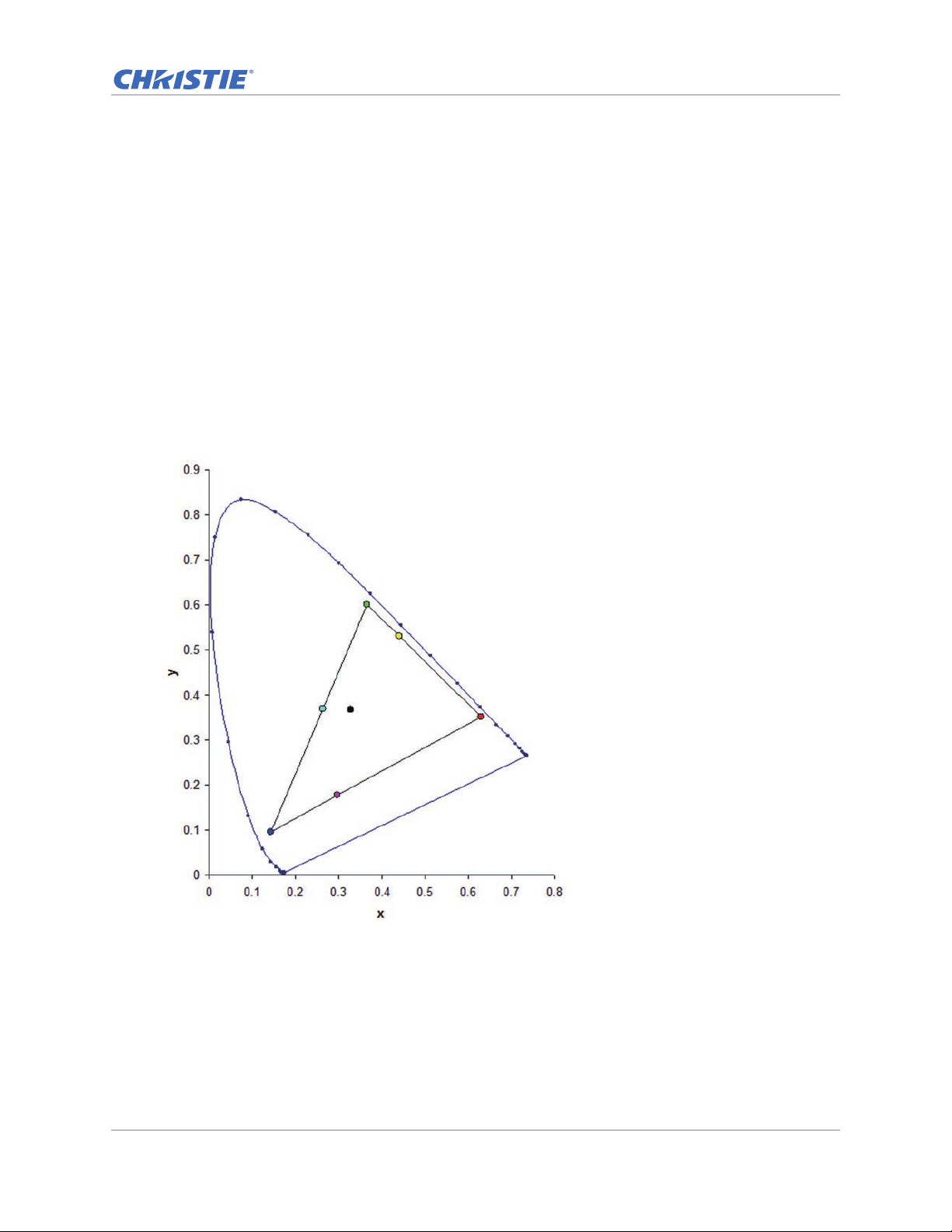
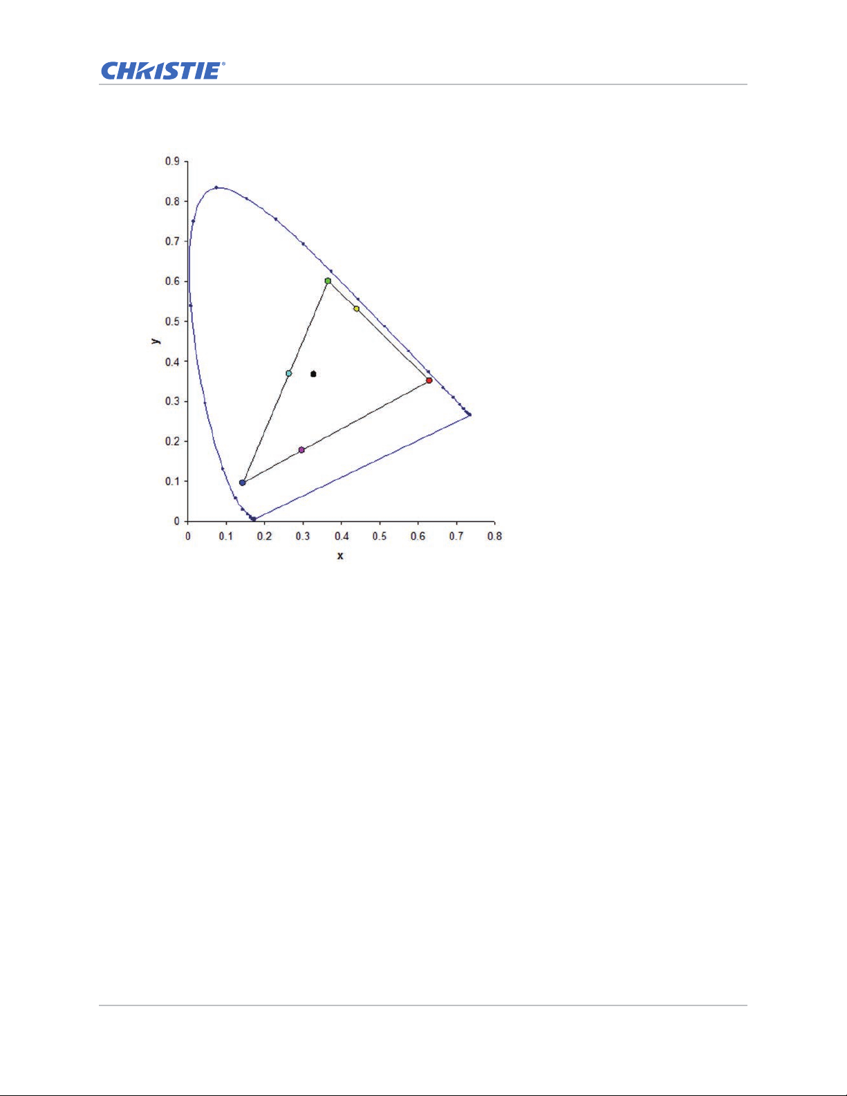
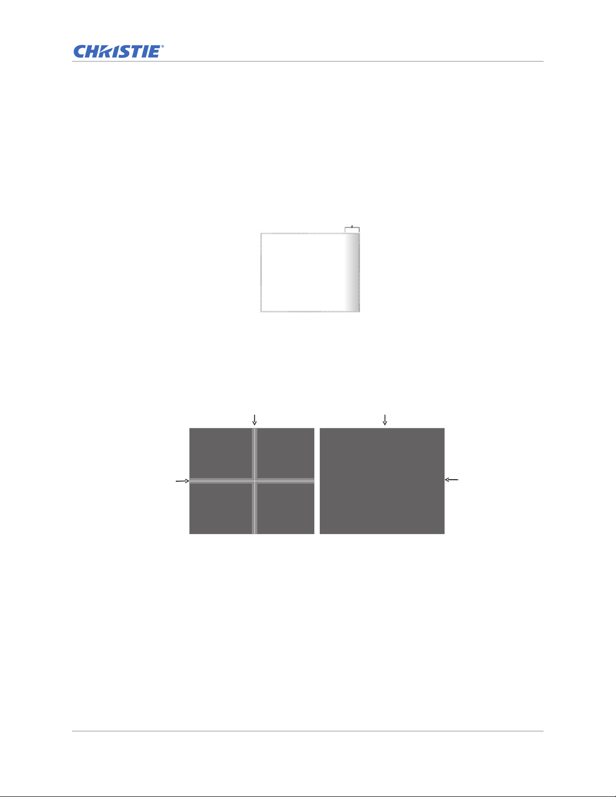
Blend
Overlap
With edge blending :
Blend
Blend
Overlap
Image
Proj. 1,1 Proj. 1,2
Proj. 2,1 Proj. 2,2
Image
Proj. 1,1 Proj. 1,2
Proj. 2,1 Proj. 2,2
Image blending
Adjust blend widths and settings to left, right, top and/or bottom sides to create a seamless multiprojector stitched image.
Image blending is only available for DWU635-GS and DHD635-GS.
What is a blend?
A blend appears as a gradient strip along an edge of a projected image. It is darkest along the
extreme edge of the image, and lightens nearer to the rest of the image (see below).
How are blends used?
Complementary blends between neighboring images can compensate for the extra brightness or
intensity where these edges overlap. By controlling blend width and other properties, you can
achieve uniformity across the group of images. Visible overlaps disappear, as shown below.
Blending regions can be defined on all sides—left, right, top, and bottom. The same gamma curve is
used for all blending regions.
GS Series 630-635 User Manual 38
020-001213-02 Rev. 1 (02-2018)
Page 39
Screen menu
Screen
Size Presets
Pixel Phase
Pixel Track
Horz Position
Vert Position
Digital Horz Zoom
Digital Vert Zoom
Digital Horz Shift
Digital Vert Shift
Ceiling Mount
Rear Projection
Geometry Correction
PIP-PBP Settings
Input Key
Auto Image
Source Info
Auto
Auto
Off
Change Sources
Wide
Select Enter Exit
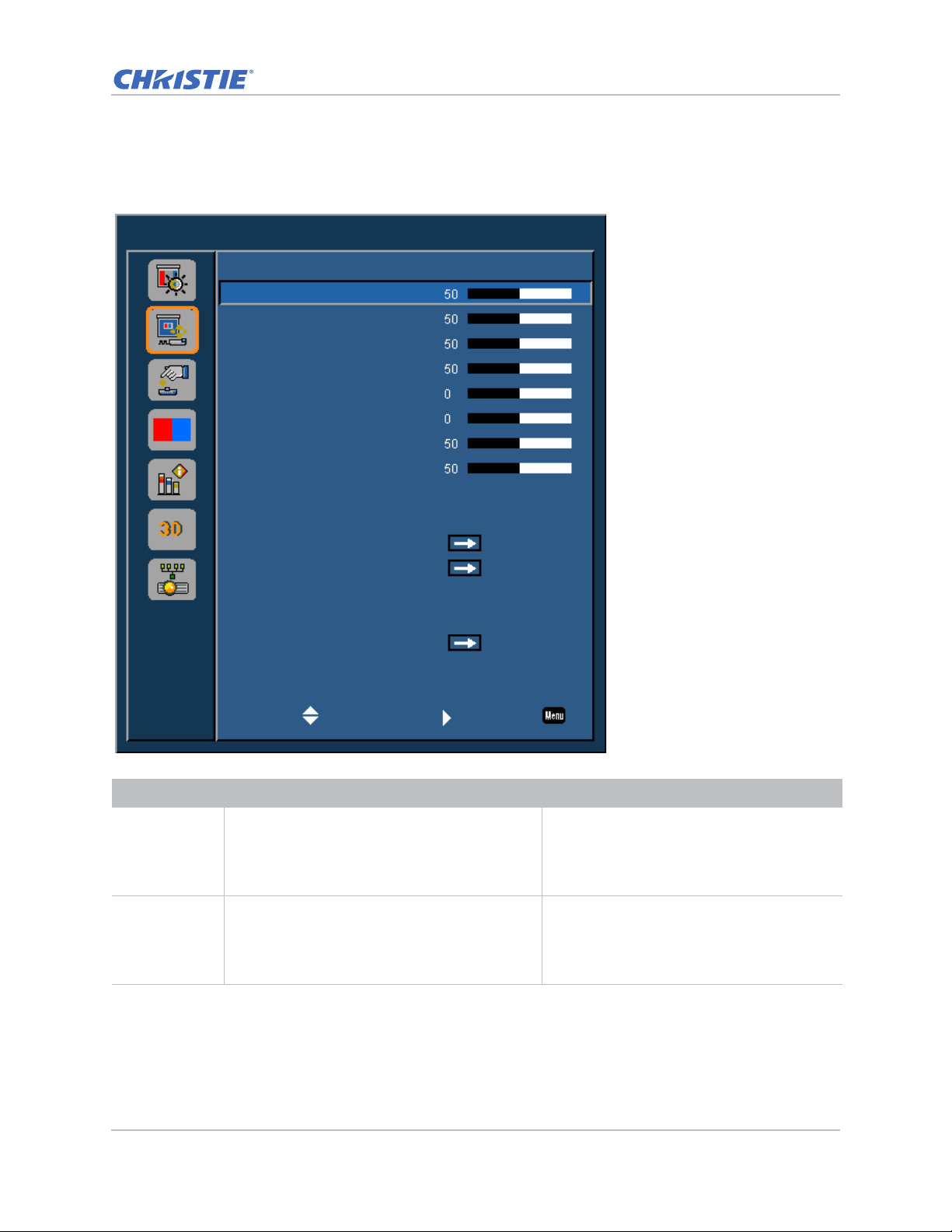
The Screen menu determines the size and position of the image on the screen.
Operation
Menu item Description Options
Size Presets Displays an image with the detected size, or
Pixel Phase Adjust the pixel phase when the image shows
resizes the image by maximizing either the
height, width, both, or resizes to the maximum
size possible while keeping the original aspect
ratio.
shimmer or noise after pixel tracking is
optimized. Pixel phase can adjust the phase of
the pixel-sampling clock relative to the incoming
signal. (Analog RGB signals only.)
• Auto—Displays with the detected size.
• 4:3—Retains 4:3 aspect ratio.
• 16:9—Retains 16:9 aspect ratio.
• 16:10—Retains 16:10 aspect ratio.
0-100
GS Series 630-635 User Manual 39
020-001213-02 Rev. 1 (02-2018)
Page 40

Menu item Description Options
Operation
Pixel Track Ensures that the image quality is consistent
across the screen, the aspect ratio is
maintained, and the pixel phase can be
optimized. Steady flickering or several soft
vertical stripes or bands across the entire image
indicates poor pixel tracking. (Analog RGB
signals only).
Horz Position Moves the image right or left within the area of
available pixels.
Vert Position Moves the image up or down within the area of
available pixels.
Digital Horz
Zoom
Changes the size of projector's display area
horizontally. If the display area has been resized
by this setting, it can be moved by changing the
Digital Horz Shift.
Digital Vert
Zoom
Changes the size of projector's display area
vertically . If the display area has been resized by
this setting, it can be moved by changing the
Digital Vert Shift settings.
Digital Horz
Shift
Digital Vert
Shift
Moves the display area horizontally if its size has
been changed by the Digital Horz Zoom setting.
Moves the display area vertically if its size has
been changed by the Digital Vert Zoom setting.
Ceiling Mount Turns the image upside down for ceiling-
mounted projection.
0-100
0-100
0-100
0-10
0-10
0-100
0-100
• Off
• On
• Auto—Projector would detect automatically.
Rear Projection Reverses the image so that you can project from
behind a translucent screen.
Geometry
Correction
Provides several ways for warping control.
For more information on geometry correction,
see Geometry Correction on page 43.
• Off
• On
• H. Keystone—Adjusts the keystone
horizontally and make a more square
image. 0-40
• V. Keystone—Adjusts the keystone
vertically and make a more square image.
0-40
• 4 Corners—Allows the image to be
squeezed to fit an area defined by moving
each of the four corners' x and y position.
• Grid Color—Choose the color of 4 corner,
green or purple.
• Reset—Restore the settings to its default
value.
• PC Mode off—User can do simple horizontal
and vertical keystone, and 4-corner control
by using the on-screen display.
• PC Mode on—User can do arbitrary warping
or blending control by using PC APP
provided separately.
GS Series 630-635 User Manual 40
020-001213-02 Rev. 1 (02-2018)
Page 41

Menu item Description Options
Operation
PIP-PBP
Settings
Displays an image with two sources in PIP mode
or PBP mode.
Refer to PIP/PBP Settings menu on page 44 and
PIP/PBP layout and size on page 46.
• Function—Toggles between displaying two
sources at once (main and PIP/PBP
images) or one source only.
• Main Source—Selects an active input to be
used as the main image.
• Sub Source—Selects an active input to be
used as the PIP/PBP.
• Location—Sets the location of the PIP
image on the screen.
• Size—Selects the PIP size to small,
medium, or large.
• Swap—Changes the main image to PIP/
PBP, and the PIP/PBP t o main image.
Swapping is available only whe n PIP/PBP is
enabled.
Input Key Lists or changes the sources. • Change Sources
• List all Sources
• Auto Source
Auto Image F orces the projector to reacquire and lock to the
input signal. This is useful when signal quality is
marginal.
• Normal—Supports all of the 4:3 input
sources.
• Wide—Supports all of the 16:9 input source
and most of the 4:3 input source.
For the 4:3 input sources not recognized by
Wide mode (for example, 1400 x 1050),
perform Auto Image using Normal mode.
Source Info Displays the current source settings. (Read-
only).
GS Series 630-635 User Manual 41
020-001213-02 Rev. 1 (02-2018)
Page 42
Operation
B
A
B
A
Ind. 1080P WUXGA
A 10.00% 7.20%
B 6.50% 5.30%
B
A
B
A
Ind. 1080P WUXGA
A 4.40% 3.41%
B 8.93% 5.46%
Geometry Correction
Geometry correction provides two ways for warping control:
• PC Mode off—User can do simple horizontal and vertical keystone, and 4-corner control by
using the on-screen display.
• PC Mode on—User can do arbitrary warping or blending control by using the PC APP provided
separately.
• PC mode is only available for DWU635-GS and DHD635-GS.
The following table provides information about the geometry correction feature compatibility:
Warp Function 4 Corners Keystone
4 Corners --
Keystone --
• The Geometry Correction function for DWU630-GS and DHD630-GS models is not supported while
using PC mode.
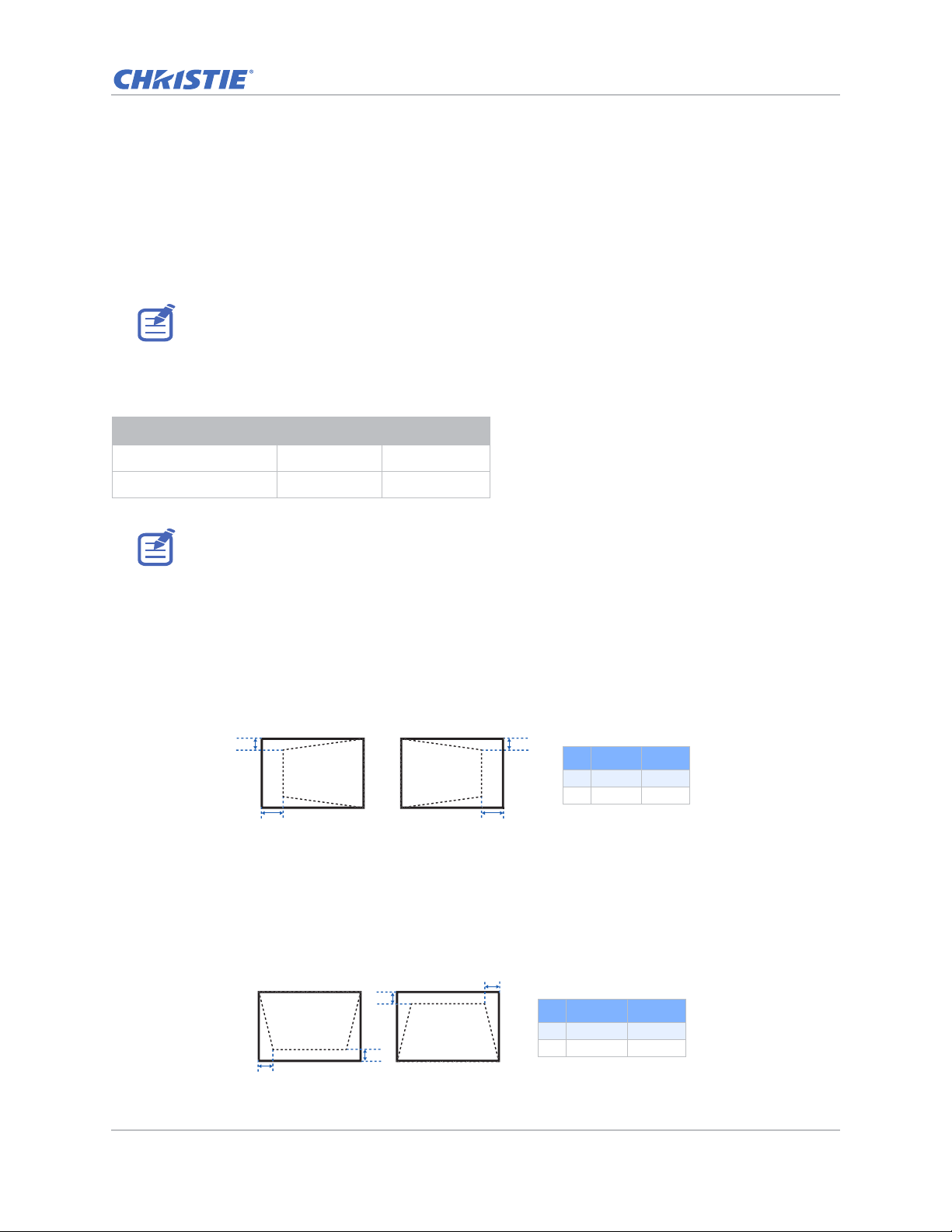
H. Keystone
Adjust the keystone horizontally and make a more square image. Horizontal keystone is used to
correct a keystoned image shape in which the left and right borders of the image are unequal in
length, and the top and bottom are slanted to one of the sides. This is intended for use with
horizontally on-axis applications.
V. Keystone
Adjust the keystone vertically and make a more square image. Vertical keystone is used to correct
a keystoned image shape in which the left and right borders of the image are unequal in length, and
the top and bottom are slanted to one of the sides. This is intended when for use with vertically onaxis applications.
GS Series 630-635 User Manual 42
020-001213-02 Rev. 1 (02-2018)
Page 43
Operation
A A
B
B
B
B
AA
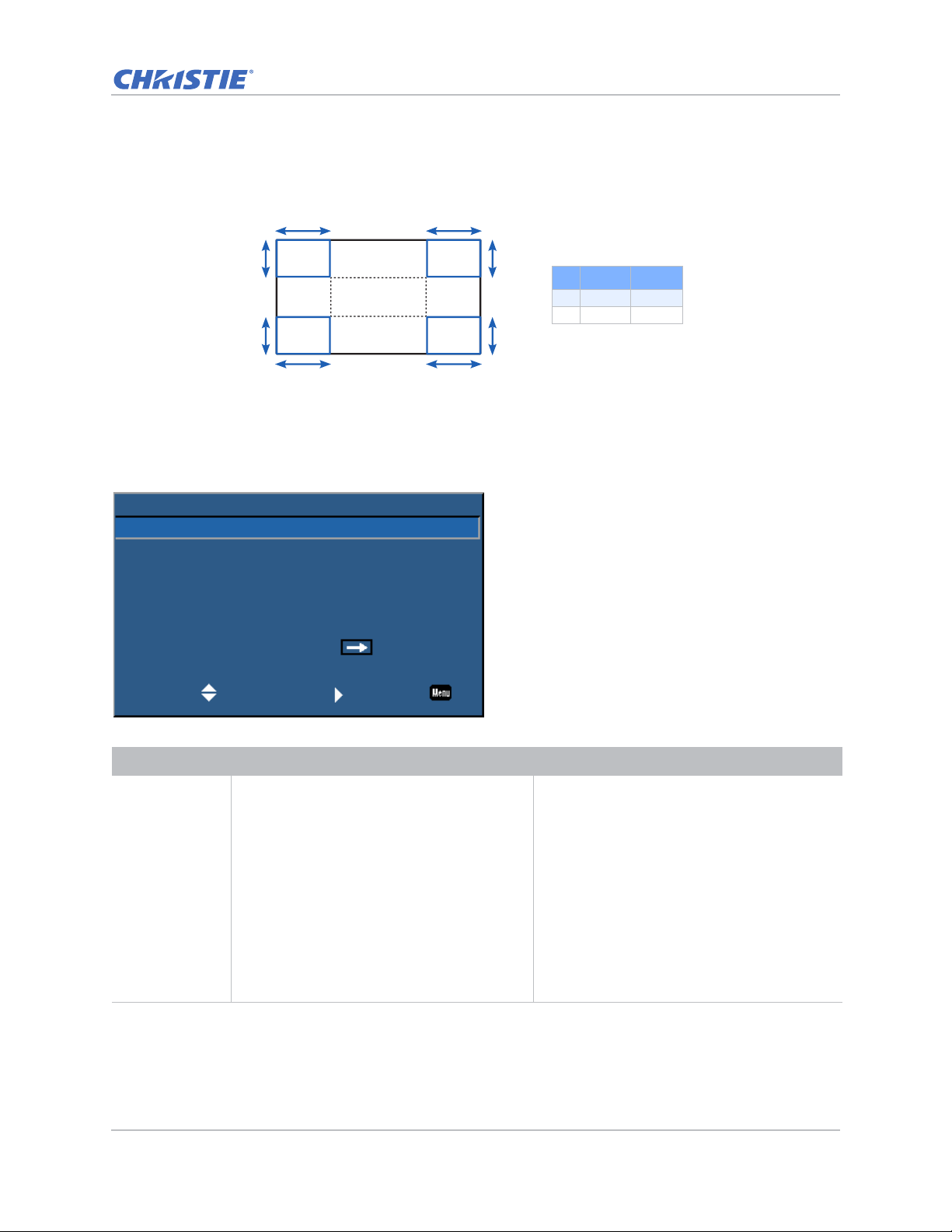
4 Corners
Allow the image to be squeezed to fit an area defined by moving each of the four corners’ x and y
position.
Ind. 1080P WUXGA
A 7.30% 7.30%
B 7.40% 6.70%
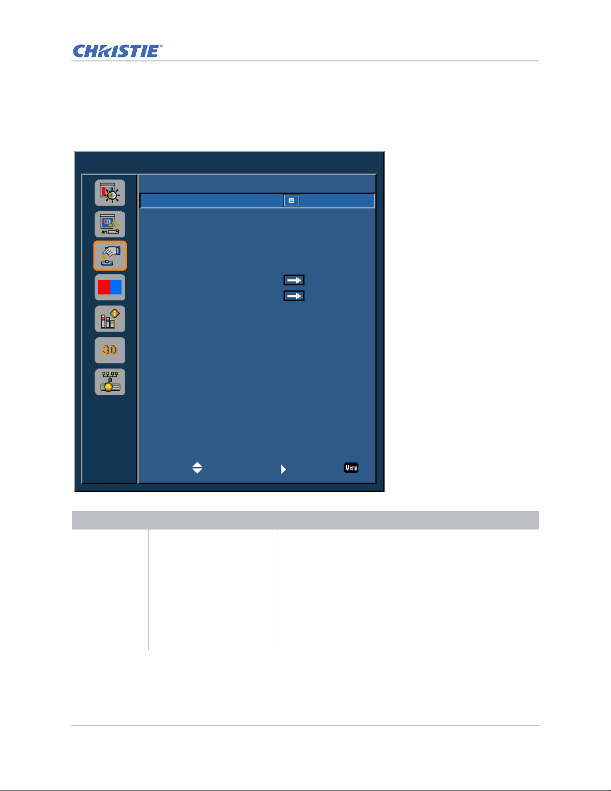
PIP/PBP Settings menu
The PIP/PBP Settings menu determines how the main and PIP/PBP inputs are handled.
PIP-PBP Settings
Function
Main Source
Sub Source
Location
Size
Swap
Select Enter Exit
PIP
VGA
HDMI-1
Top Left
Small
Menu item Description Options
Function Toggles between displaying two sources at
once (Main and PIP/PBP images) or one
source only.
• Off—Displays image from the main source
only.
• PBP—Displays images from two sources by
separating the screen into two parts. One
source is displayed on the main screen and
another source is displayed in an inset
window.
• PIP—Displays images from two sources by
separating the screen into half. One source
is displayed on the left side of the screen
and the other source on the right side of the
screen.
Refer to PIP/PBP layout and size on page 46.
GS Series 630-635 User Manual 43
020-001213-02 Rev. 1 (02-2018)
Page 44

Menu item Description Options
Operation
Main Source Selects an active input to be used as the main
image.
Sub Source Selects an active input to be used as the sub
image.
Location Sets the location of the PIP/PBP image on the
screen.
Refer to PIP/PBP layout and size on page 46.
Size Selects the PIP/PBP si ze to small, medium, or
large.
Swap Changes the main image to PIP/PBP, and the
PIP/PBP to main image.
Swapping is available only when PIP/PBP is
enabled.
• VGA
• HDMI-1
• HDMI-2
• DVI
• HDBaseT
• VGA
• HDMI-1
• HDMI-2
• DVI
• HDBaseT
• Top Left
• Top Right
• Bottom Left
• Bottom Right
—
—
GS Series 630-635 User Manual 44
020-001213-02 Rev. 1 (02-2018)
Page 45
Operation
PPP
P
P
P
P
P
PPP
P
P
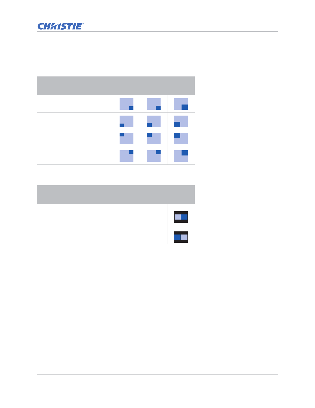
PIP/PBP layout and size
A P indicates the primary source region (lighter color) and an asterisk (*) indicates both regions are
the same size.
PIP Layout
PIP-Bottom Right
PIP-Bottom Left
PIP-Top Left
PIP-Top Right
PBP Layout
PBP, Main Left
PBP, Main Right
PIP Size
Small Medium Large
P
PBP Size
Small Medium Large
-- --
-- --
GS Series 630-635 User Manual 45
020-001213-02 Rev. 1 (02-2018)
Page 46
Operation
Settings
Language
Menu Location
LAN (Standby)
Test Pattern
Direct Power On
Hot-Key Settings
Reset to Default
Service
English
Communication mode
Checkerboard
Off
Blank Screen
Select Enter Exit
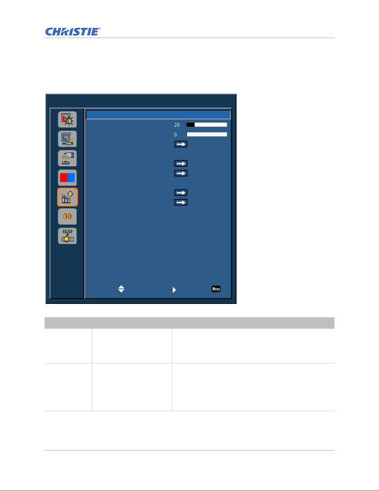
Settings Menu
The Settings menu sets the language, menu location, LAN (standby), and other preferences for the
projector.
Menu item Description Options
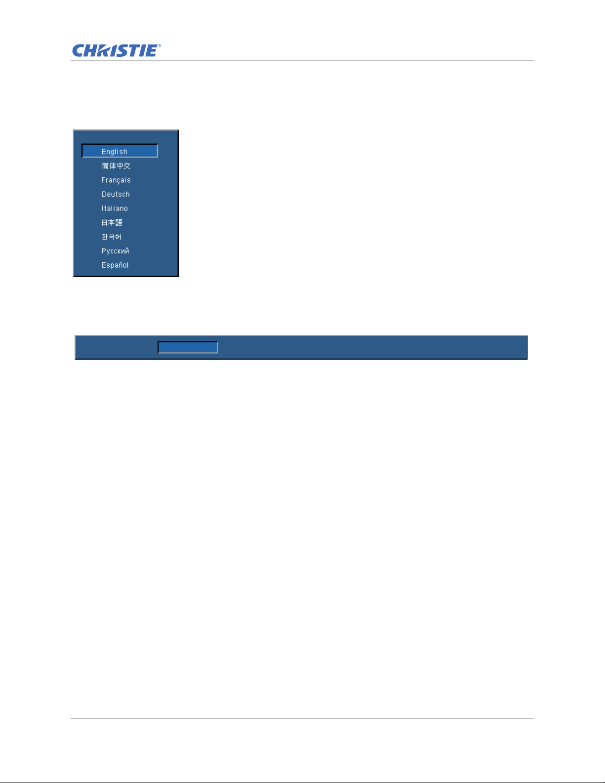
Language Selects an available language
for the on-screen display.
GS Series 630-635 User Manual 46
020-001213-02 Rev. 1 (02-2018)
• English
• Chinese (Simplified)
• French
• German
• Italian
• Japanese
• Korean
• Russian
• Spanish
Page 47

Menu item Description Options
Operation
Menu Location Sets up the on-screen displa y
menu location.
LAN (Standby) Determines the power modes
for projector.
Test Pattern Chooses the required internal
test pattern to display.
Direct Power On Automatically turns the
projector on when electrical
power is connected.
Hot-Key Settings Assigns a different function to
the hot key on the IR remote
keypad by highlighting the
function in the list and
pressing Enter.
Chooses a function that does
not already have a dedicated
button, and assign the hot
key to that function, allowing
you to quickly and easily use
the chosen function.
Reset to Default Restores all settings to their
default value. It does not
reset network but it resets
RS232.
Service Displays projector
information, sets test
patterns, error logs, and high
temperature warnings.
• Left Top
• Right Top
• Center
• Left Bottom
• Right Bottom
• 0.5W mode—Low power mode.
• Communication mode—Normal power mode.
• None
• Grid
• White
• Black
• Checkerboard
• Color Bars
• On
• Off
• Blank Screen
• Aspect Ratio
• Freeze Screen
• Projector Info
• Yes
• No
• Projector Info—Displays the current projector settings.
(Read-only)
• Factory Reset—Restores all settings to their default value. It
does not reset network but it resets RS232.
• Test Pattern—Sets the required internal test pattern to
display. To turn off a test pattern, select Off.
• Wheel Index (2x)—Sets the wheel index to Speed 2X. Only
use this setting when a new main board is installed, and the
picture quality needs to be optimized.
• Wheel Index (3x)—Sets the wheel index to Speed 3X. Only
use this setting when a new main board is installed, and the
picture quality needs to be optimized.
• Error Log—Shows the projector error log for debug.
• Laser Diode Info—Displays the information of each laser
diode bank including its voltage, current, and temperature.
GS Series 630-635 User Manual 47
020-001213-02 Rev. 1 (02-2018)
Page 48
Operation
Language
Test Pattern None Grid White Black Checkerboard Color Bars
Language menu
Select an available language for the on-screen display.
Test Pattern menu
Choose the required internal test pattern to display, or select None to turn off a test pattern.
GS Series 630-635 User Manual 48
020-001213-02 Rev. 1 (02-2018)
Page 49
Light Source menu
Light Source
Light Source Mode
Constant Power
Light Source Info
Constant Power
Select Enter Exit
The Light Source menu sets the light source mode and power preferences.
Operation
Menu item Description Options
Light Source
Mode
Constant Power Sets the value of the laser diode power. 0-99
Light Source
Info
GS Series 630-635 User Manual 49
020-001213-02 Rev. 1 (02-2018)
Sets the light source mode. • Constant Power
• Constant Intensity
• ECO 1—The factory default brightness is
80%.
• ECO 2—The factory default brightness is
50%.
Displays the total hours of the projector, the
total hours of the laser diode that have been
used, and information on the light sensor
calibration.
—
Page 50
Operation
Options
Splash Screen
Auto Shutdown
Sleep Timer
Lens Settings
High Altitude
PIN Protect
Remote Settings
Information Hide
Backlight Preferences
Information
Factory Logo
Off
Off
Select Enter Exit
Options Menu
The Options menu allows to select the splash screen, configure auto shutdown parameters, set
sleep timer, and configure other options for the projector.
Menu item Description Options
Splash Screen Selects the splash screen. • Factory Logo
Auto Shutdown Automatically turns the
GS Series 630-635 User Manual 50
020-001213-02 Rev. 1 (02-2018)
projector off after no signals
are detected for a preset
number of minutes. If an
active signal is received
before the projector powers
down, the image is displayed.
• Blue
• Black
• White
0-120 mins
Page 51

Menu item Description Options
Operation
Sleep Timer Allows the projector to
0-990 mins
automatically power off after
it has been on for a specified
amount of time.
Lens Settings Adjusts the lens parameters. • Focus—Adjusts the focus point of the image.
• Zoom—Adjust the zoom of the image in or out.
• Lens Shift—Shifts the lens up and down, or left and right.
• Lock Lens Motors—Selects this function to prevent all lens
motors from moving. It will disable the Zoom, Focus,
Horizontal and Vertical Position settings, effectively locking
out any changes and overriding all other lens features. This
is particularly useful to prevent accidental lens position
changes in multi-projector installations.
• Lens Calibration—Calibrates to move the lens back to center.
High Altitude Enables or disables high
altitude mode.
• On—Enables high altitude mode for altitudes >/= 2000 m.
The fan operates at high speed to ensure sufficient air flow
for high altitudes.
• Off—Disables high altitude mode. For altitudes below
2000m.
PIN Protect Protects your projector with a
—
password. Once enabled, you
must enter the password
before you can project an
image.
Remote Settings Turns on/off remote settings. • Top
• Front
• HDBaseT
• Projector Address. 0-9.
Information Hide Hides or displays projector
settings.
Backlight
Preferences
Controls the backlight
behavior and status LED.
Information Displays the projector
• On
• Off
• Keypad Backlight
• Status LED
—
settings. (Read-only)
GS Series 630-635 User Manual 51
020-001213-02 Rev. 1 (02-2018)
Page 52
Information
Exit
Model Name
Serial Number
Native Resolution
Motor FW
Main Input
Main Signal Format
Main Pixel Clock
Main Sync Type
Main Horz Refresh
Main Vert Refresh
PIP/PBP Input
PIP/PBP Signal Format
PIP/PBP Pixel Clock
PIP/PBP Sync Type
PIP/PBP Horz Refresh
PIP/PBP Vert Refresh
Light Source Power
Total Projector Hours
Light Source Hours
Standby Mode
Lens Lock Settings
IP Address
DHCP
System Temperature
VGA
Digital Video
Sync On Green
Communication mode
Allow
Off
Operation
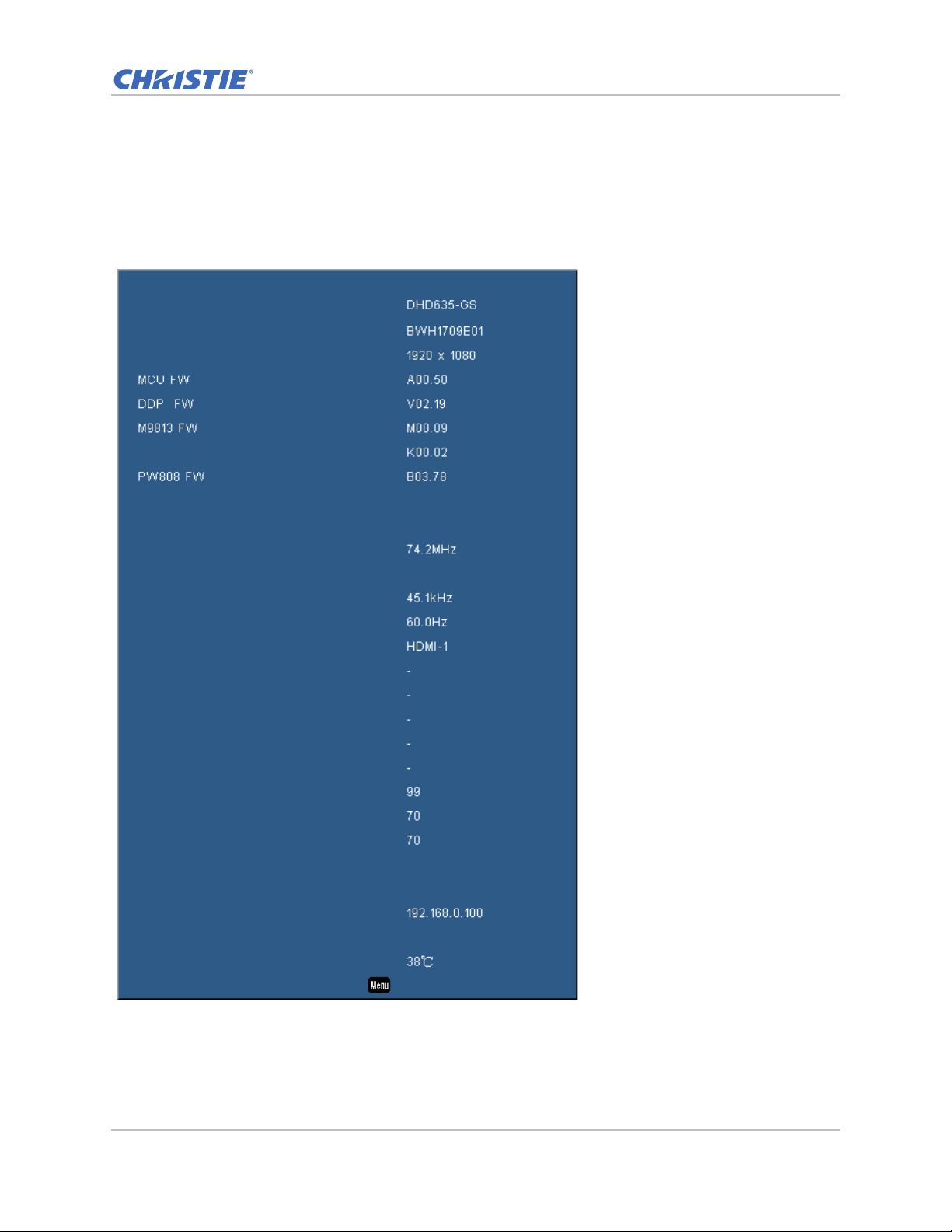
Information menu
The read-only Information menu lists a variety of details about the standard and optional
components currently detected in the projector.
For DHD Models
GS Series 630-635 User Manual 52
020-001213-02 Rev. 1 (02-2018)
Page 53
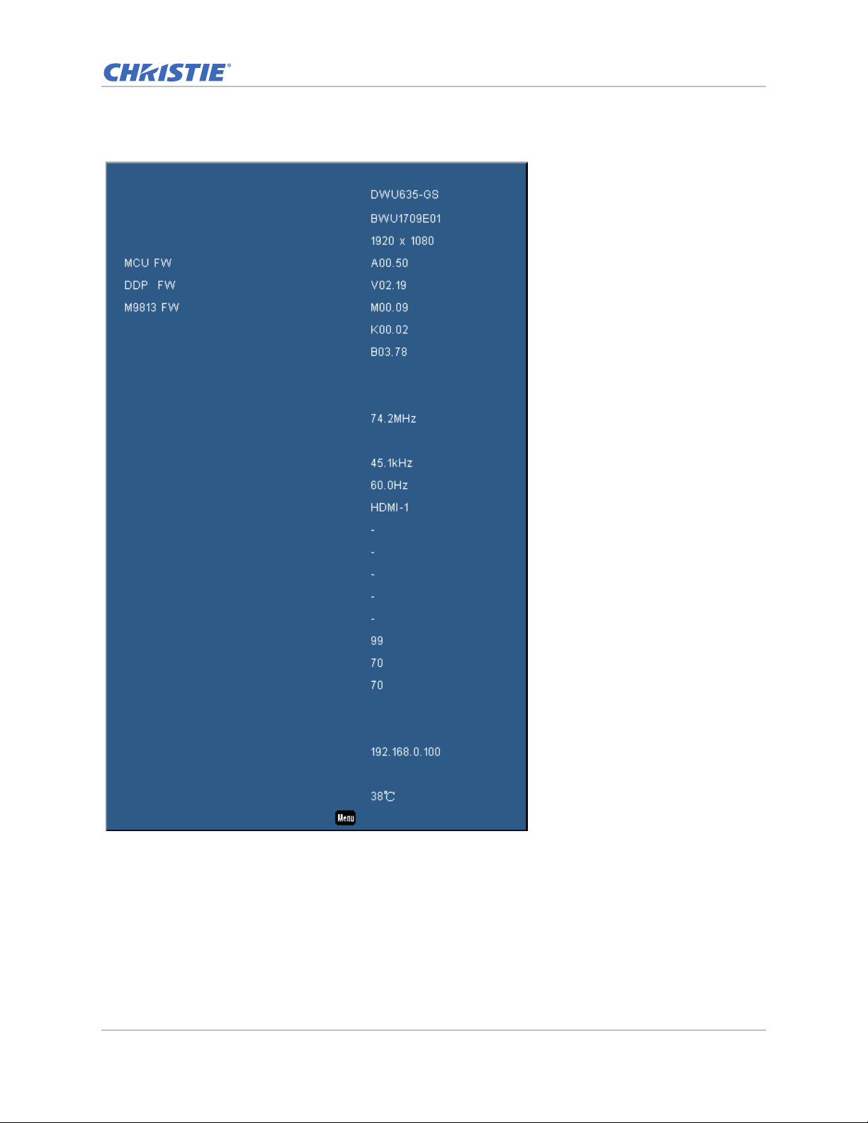
Information
Exit
Model Name
Serial Number
Native Resolution
Motor FW
PW808 FW
Main Input
Main Signal Format
Main Pixel Clock
Main Sync Type
Main Horz Refresh
Main Vert Refresh
PIP/PBP Input
PIP/PBP Signal Format
PIP/PBP Pixel Clock
PIP/PBP Sync Type
PIP/PBP Horz Refresh
PIP/PBP Vert Refresh
Light Source Power
Total Projector Hours
Light Source Hours
Standby Mode
Lens Lock Settings
IP Address
DHCP
System Temperature
VGA
Digital Video
Sync On Green
Communication mode
Allow
Off
Operation
For DWU Models
GS Series 630-635 User Manual 53
020-001213-02 Rev. 1 (02-2018)
Page 54
3D menu
3D
3D
3D Invert
3D Format
3D Sync Out
Frame Delay
L/R Reference
Auto
Off
To Emitter
1ST Frame
Select Enter Exit
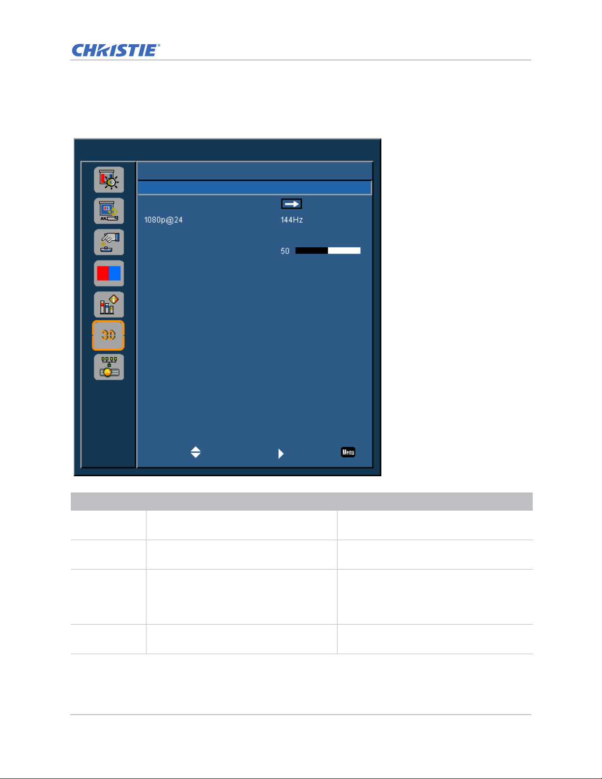
The 3D menu sets the usage of 3D function and its settings.
Operation
Menu item Description Options
3D Enables 3D content detection. • On
3D Invert Inverts the 3D sync signal when using a single
projector.
3D Format Sets the 3D format. Supports mandatory 3D
formats and frame sequential 3D@120Hz.
1080p@24 Sets the 3D resolution 1080p@24 frequency. • 96Hz
GS Series 630-635 User Manual 54
020-001213-02 Rev. 1 (02-2018)
• Auto
• On
• Off
• Frame Packing
• Side-by-Side(Half)
• Top and Bottom
• Frame Sequential (635-GS only)
• 144Hz
Page 55
Menu item Description Options
Communications
LAN
Network
Serial Port Baud Rate
Serial Port Echo
Serial Port Path
On
Select Enter Exit
Operation
3D Sync Out Transmits a 3D sync signal by the 3D sync
output corrector to the emitter or to the next
projector for 3D blending purposes.
Frame Delay Corrects asynchronous displaying of images
under 3D blending.
L/R Reference Source of the left or right reference. • 1st Frame—This is used for single 3D
—
—
projector.
• Field GPIO—Select Field GPIO to make the
first 3D output signal the same for multiprojectors application.
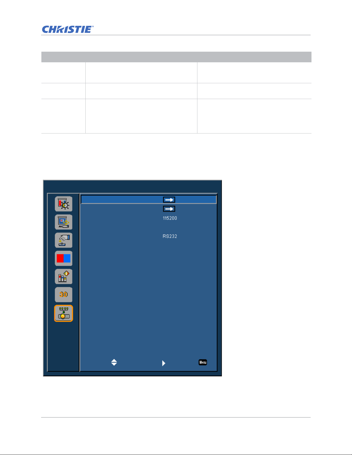
Communications menu
The Communications menu sets the LAN parameters, network status, and other settings for the
projector.
GS Series 630-635 User Manual 55
020-001213-02 Rev. 1 (02-2018)
Page 56
Operation
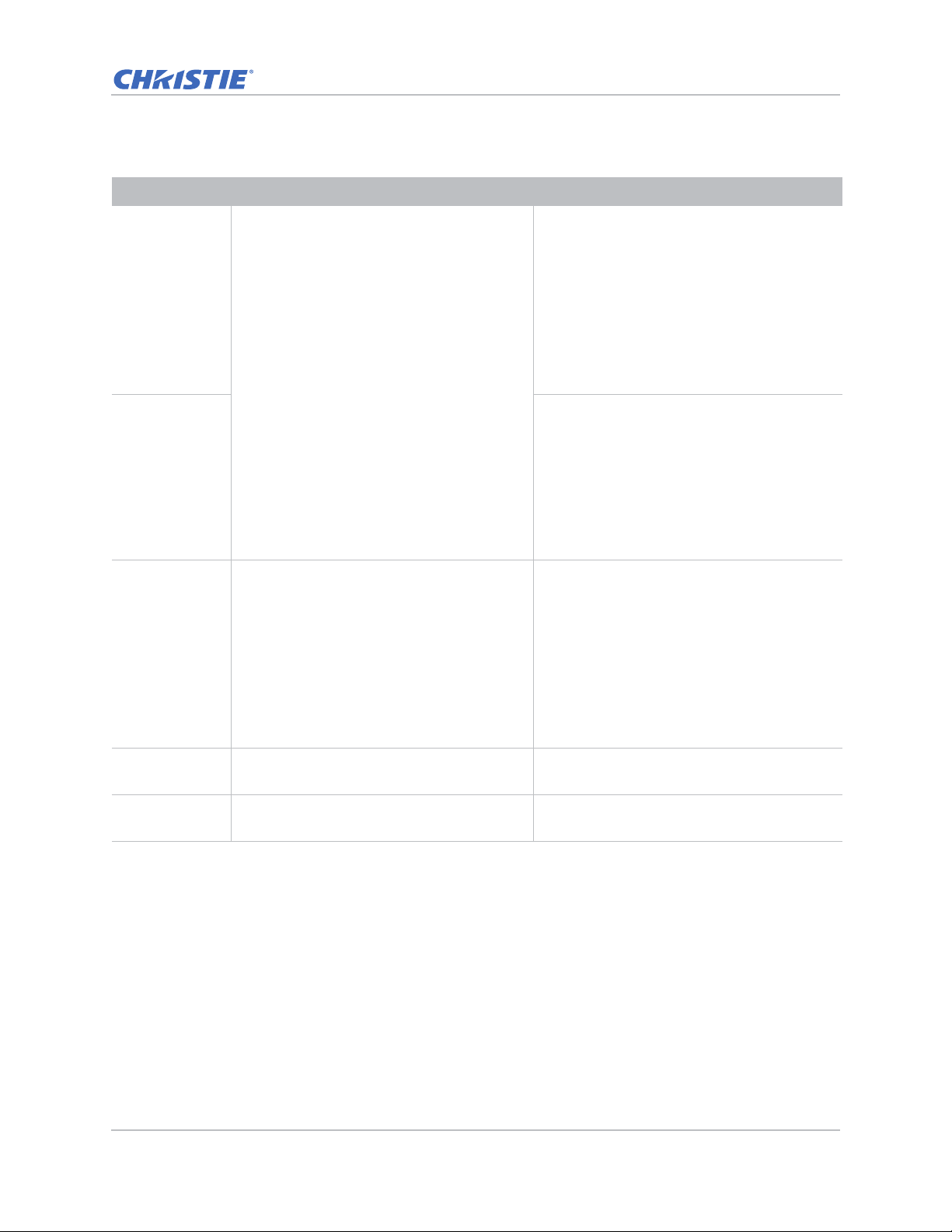
Menu item Description Options
LAN Determines the communication settings. • DHCP—Turns the DHCP on or off.
• IP Address—Assigns the network IP address.
• Subnet Mask—Assigns the network subnet
mask.
• Default Gateway—Assigns the network
default gateway.
• MAC Address—Displays the network MAC
address value.
• Apply—Apply the LAN configuration when
the setting is changed or added.
Network • Projector Name—Displays the projector
name.
• Show Network Messages— Turns network
messages on or off.
• Restart Network—Restarts the network.
• Network Factory Reset—Performs factory
reset on the network settings. The Projector
Name, IP Address (LAN), Start IP and End
IP, and SNMP settings can be reset.
Serial Port Baud
Rate
Selects the serial port and baud rate. • 1200
• 2400
• 4800
• 9600
• 14400
• 19200
• 38400
• 57600
• 115200
Serial Port Echo Controls whether the serial port echoes
characters.
Serial Port Path Sets the serial port path to RS232 or
HDBaseT.
GS Series 630-635 User Manual 56
020-001213-02 Rev. 1 (02-2018)
• Off
• On
• RS232
• HDBaseT
Page 57
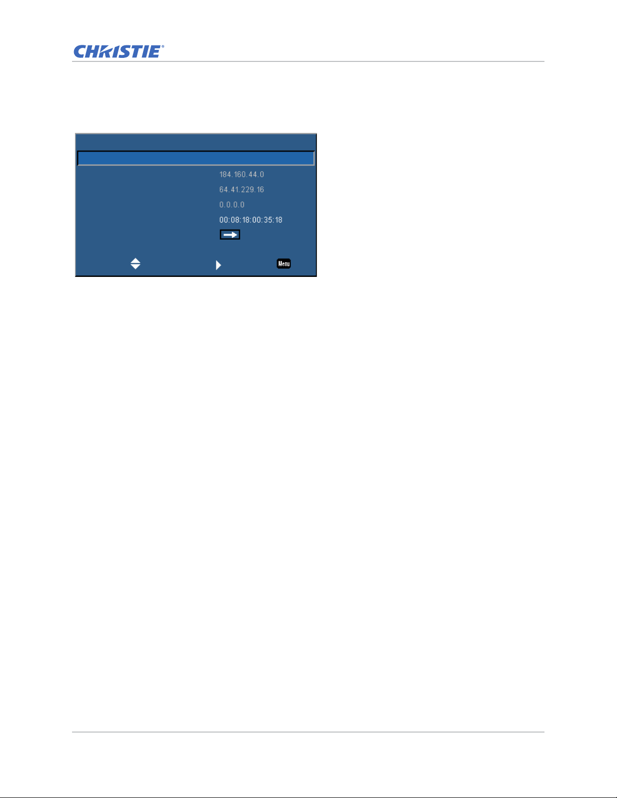
LAN settings
LAN
DHCP
IP Address
Subnet Mask
Default Gateway
MAC Address
Apply
On
Select Enter Exit
The LAN menu sets the DHCP, IP address, and other network settings for the projector.
Operation
GS Series 630-635 User Manual 57
020-001213-02 Rev. 1 (02-2018)
Page 58
Operation
Web user interface
The web user interface provides an alternate way to access the menu functionality on the projector.
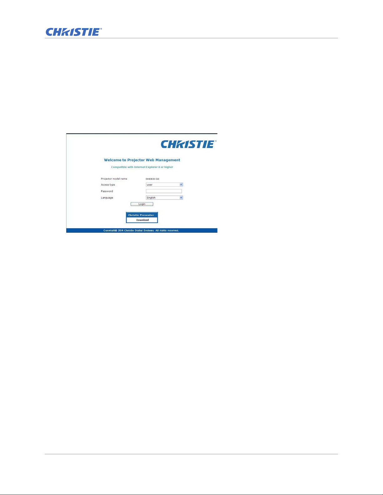
Logging on to the web user interface
Log onto the web user interface by following the steps below.
1. Open a web browser and type the IP address (in the address bar) assigned to your projector.
2. From the Access type list, select the log in level.
3. In the Password field, type the password.
4. From the Language list, select the appropriate language.
5. To access the Main window, click Login.
GS Series 630-635 User Manual 58
020-001213-02 Rev. 1 (02-2018)
Page 59
Operation
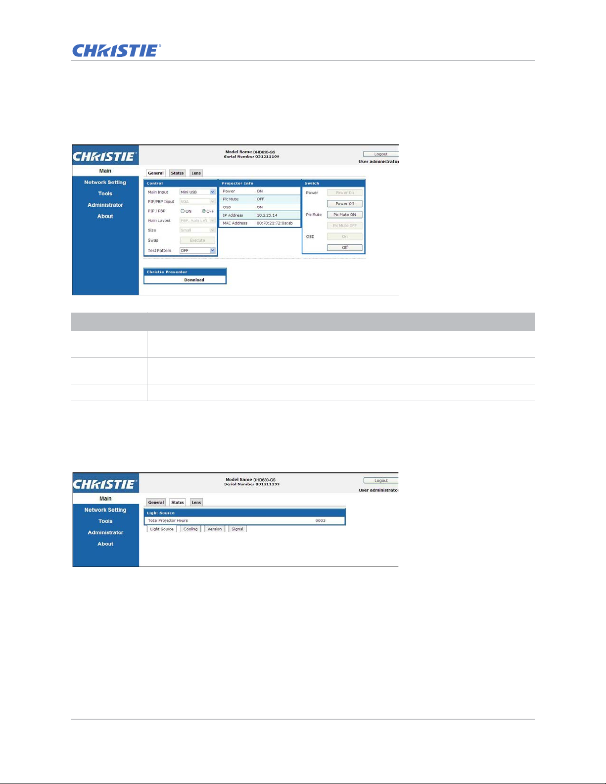
Main tab–General
Displays information about the projector, its power status, and what is selected for the main and
PIP/PBP input sources.
Panel Description
Control Selects main source/PIP source, enables or disables PIP/PBP, changes the layout or PIP size,
Projector
Information
Switch Switches the on or off status of Power, Pic Mute, and on-screen display.
swap, and change the test pattern.
Check the projector information for power status, Pic mute status, on-screen display status, IP
address, and MAC address.
Main tab–Status
Displays the current status of light source, cooling (fans), version numbers, and signal (source)
information.
GS Series 630-635 User Manual 59
020-001213-02 Rev. 1 (02-2018)
Page 60
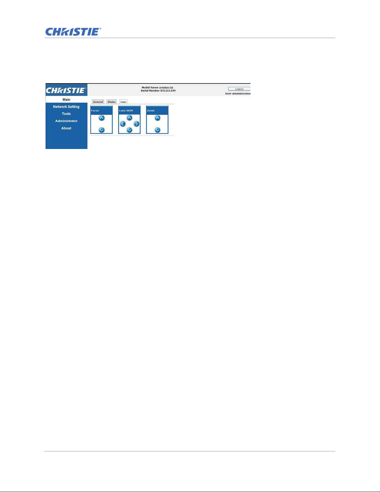
Main tab–Lens
Controls the focus, lens shift, and zoom adjustments for the lens.
Operation
GS Series 630-635 User Manual 60
020-001213-02 Rev. 1 (02-2018)
Page 61
Operation
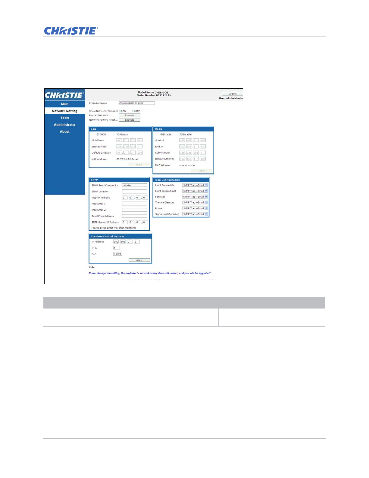
Network
If you change a setting, the network subsystem of the projector may restart, and you may be
logged off.
Panel Description
Restart
Network
GS Series 630-635 User Manual 61
020-001213-02 Rev. 1 (02-2018)
Executes a network restart. This does not change
any of the network settings.
Fields
Page 62
Operation
Panel Description
Network
Factory Reset
LAN Setting
Panel
Execute a network factory reset. Network settings
may be reset to the following default values.
Projector Name = Christie@ + Serial Number
Show Network Messages = ON
Sets if the projector must obtain an automatically
assigned IP address through DHCP or if the user sets
the address manually.
Fields
LAN settings:
• Manual
• IP Address = 192.168.0.100
• Subnet Mask = 255.255.255.0
• Default Gateway = 192.168.0.100
WLAN settings:
• Enabled
• Start IP = 192.168.1.100
• End IP = 192.168.1.120
• Subnet Mask = 255.255.255.0
• Default Gateway = 192.168.1.100
SNMP settings:
• SNMP Read Community = private
• Trap IP Address = 0.0.0.0
• SMTP IP Address = 0.0.0.0
• All other settings are cleared or
blanked
Trap Configuration:
• All items = SNMP Trap + Email
For the TCP/IP setting, enter the IP
address, netmask, and default gateway
address.
WLAN Setting
Enables or disables the wireless LAN of the projector . Enter the IP address range, netmask, and
Panel
SNMP Panel Provides network administrators with a common
way to manage their network devices from a single
remote location.
Administrators can use the Simple Network
Management Protocol (SNMP) interface to query a
number of devices to see their current status or
configuration.
Operators can change configuration values and
configure trap notifications to be sent when certain
events occur (for example, loss of signal, power
state change, and so on).
Emails are sent to the mail server configured in the
projector settings. Up to two user email accounts
can be selected. Important information regarding
the event is located in the body content of the email.
SNMP T r aps are notification s sent from the projector
and are only received by a trap receiver (MIB
Browser) in the computer.
default gateway for the wireless LAN.
• SNMP Read Community (default
setting: private)—Plain text password
that must also be entered in the MIB
browser. This password allows various
settings in the projector to be queried.
• SNMP Location (default setting:
blank)—Use as a description to where a
projector is located in a building. SNMP
emails sent specify this loca tion.
• Trap IP Address (default setting:
0.0.0.0)—Fill in this field with the IP
address of the computer, on which you
want to view received traps from the
projector.
• Trap Email 1/2 (default setting:
Blank)—Set the Trap Email 1 and 2 to
an email address configured under the
mail server entered in the SMTP Server
IP Address field.
• Email from Address (default setting:
blank)—Set the name of the source of
the SNMP emails.
• SMTP Server IP Address (default
setting: 0.0.0.0)—Enter the IP address
of the mail server.
GS Series 630-635 User Manual 62
020-001213-02 Rev. 1 (02-2018)
Page 63
Operation
Panel Description
Trap
Configuration
Panel
Crestron
Control System
Panel
Set the SNMP actions for the system events. • SNMP Trap
Provides the information to connect to a Creston
device.
Fields
• + Email
• Email
• SNMP Trap
• Disabled
Enter the IP address, IP ID, and port of
Crestron device for the connection.
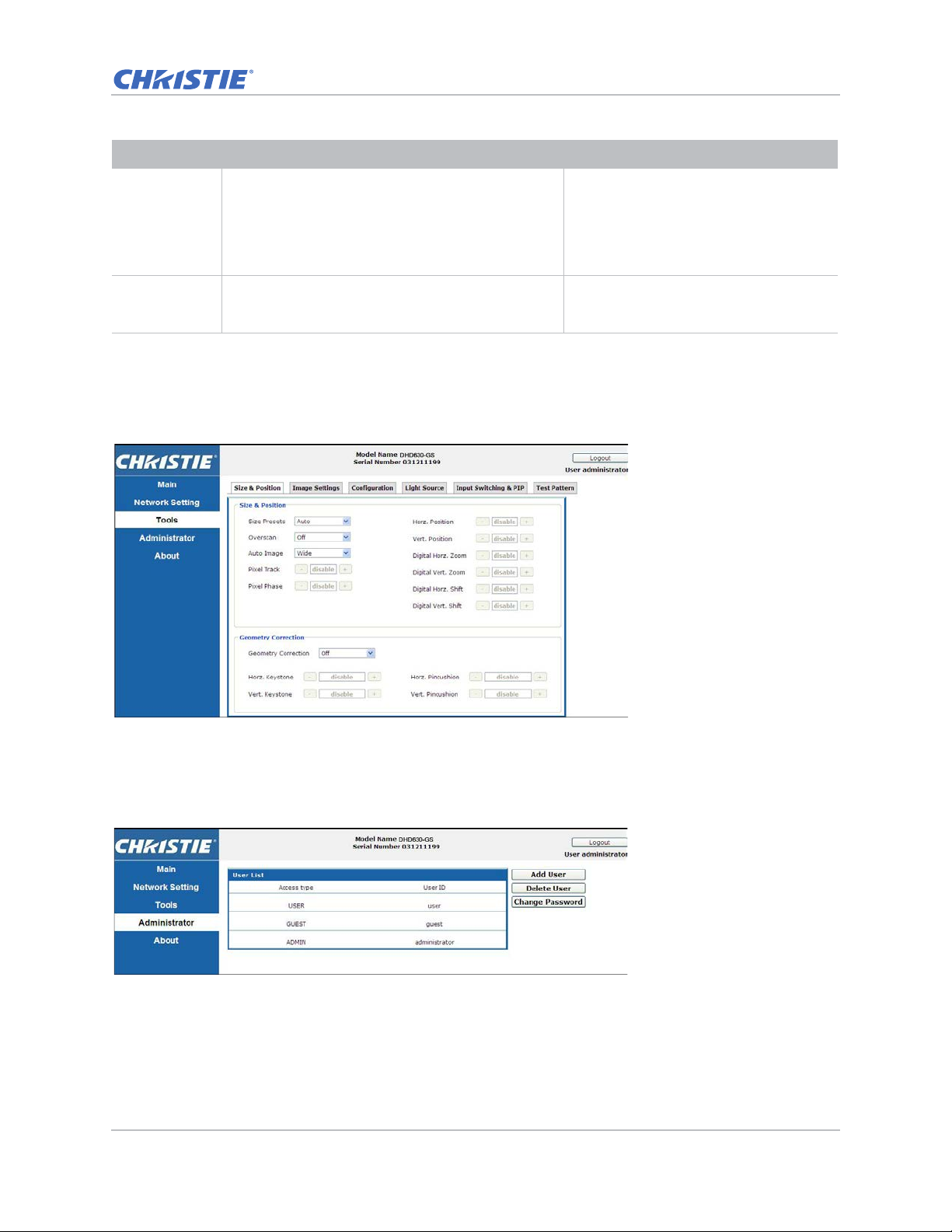
Tool s
Use the Tools pages to control size & position, image settings, configuration, light source, input
switching, PIP, and test patterns.
Administrator Page
Add or delete a user or change password.
GS Series 630-635 User Manual 63
020-001213-02 Rev. 1 (02-2018)
Page 64
Operation
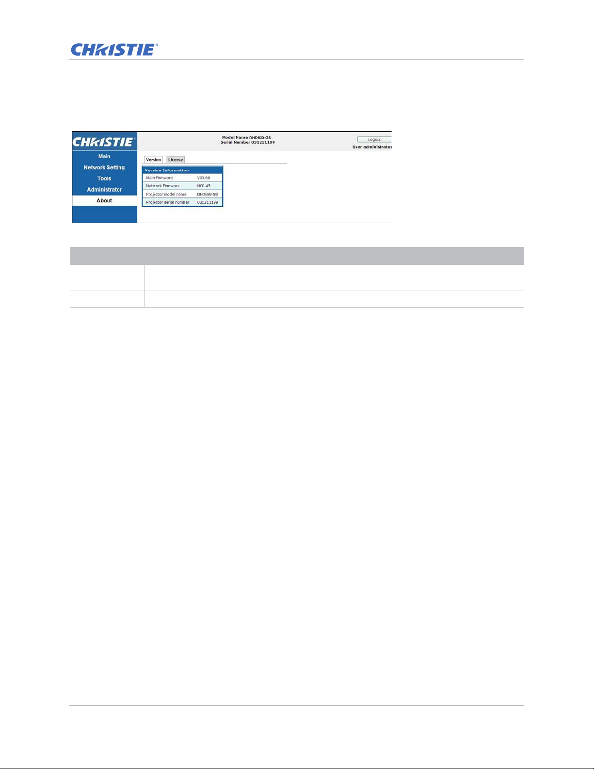
About Page
The About page provides version and license information about GS Series.
Tab Description
Version Views the main firmware version, network firmware version, projector model name, and
projector serial number.
License Displays the license information of the computer program.
GS Series 630-635 User Manual 64
020-001213-02 Rev. 1 (02-2018)
Page 65

Troubleshooting
If you cannot resolve an issue using the information provided in this section, contact your reseller
or service center.
No image appears on screen
The image does not appear on the screen.
Resolution
• Make sure all the cables and power connections are correctly and securely connected.
See Installation on page 19 for more details.
• Check if the Light Status LED is in Green.
• Make sure you have removed the lens cap and the projector is switched on.
Incorrectly displayed image
The image is partial, is scrolling, or is otherwise incorrectly displayed.
Resolution
If using a PC:
1. On control panel or IR remote keypad, press AUTO.
2. Select My Computer > Control Panel.
3. Double-click Display.
4. Select the Settings tab.
5. Verify your display resolution setting is lower than or equal to WUXGA (1920 × 1200).
6. Click Advanced Properties.
7. If the projector is still not projecting the entire image, change the monitor display:
a. Verify the resolution setting is lower than or equal to WUXGA (1920 × 1200).
b. Switch to the Monitor tab.
GS Series 630-635 User Manual 65
020-001213-02 Rev. 1 (02-2018)
Page 66

Troubleshooting
c. Click Change.
d. Click Show all devices.
e. Under the SP box, select Standard monitor types.
f. Under the Models box, select the appropriate resolution mode.
g. Verify that the resolution setting of the monitor display is lower than or equal to WUXGA
(1920 × 1200).
If using a Notebook:
1. On control panel or IR remote keypad, press AUTO.
2. Adjust resolution of the computer.
3. To send signal out from notebook to projector, press the keys listed below for your Notebook
manufacturer (for example, [Fn]+[F4]):
Notebook brand Function keys
Acer [Fn]+[F5]
Asus [Fn]+[F8]
Dell [Fn]+[F8]
Gateway [Fn]+[F4]
IBM/Lenovo [Fn]+[F7]
HP/Compaq [Fn]+[F4]
NEC [Fn]+[F3]
Toshiba [Fn]+[F5]
Mac Apple System Preference > Display > Arrangement > Mirror display
4. If you experience difficulty changing resolutions or your monitor freezes, restart all equipment
including the projector.
Presentation is not displayed
The screen of the Notebook or PowerBook computer is not displaying your presentation.
Details
Some Notebook PCs may deactivate their own screens when a second display device is in use. Each
has a different method of reactivation.
Resolution
Refer to your computer manual for information on changing the method of reactivation.
GS Series 630-635 User Manual 66
020-001213-02 Rev. 1 (02-2018)
Page 67

Troubleshooting
Unstable or flickering images
The image is unstable or is flickering when projected.
Resolution
• To correct the pixels, use Pixel Track and Pixel Phase.
• Change the monitor color setting on your computer.
Vertical flickering bar
The image has a vertical, flickering bar when projected.
Resolution
• To make an adjustment, use Auto Image.
• Check and reconfigure the display mode of your graphic card to make it compatible with the
projector.
Image is out of focus
The image is out of focus on the screen.
Resolution
• Make sure both lens caps (front and back) are removed.
• Adjust the lens focus to fit the screen.
• Make sure the projection screen is between the required distance.
Image is stretched
The image is stretched when displaying a 16:9 DVD title.
Details
When you play anamorphic DVD or 16:9 DVD, the projector shows the best image if the projector
display mode is set to 16:9 in the on-screen display.
GS Series 630-635 User Manual 67
020-001213-02 Rev. 1 (02-2018)
Page 68

Troubleshooting
Resolution
• If you play 4:3 format DVD titles, change the format to 4:3 in the projector on-screen display.
• If the image is still stretched, adjust the aspect ratio by setting the display format as 16:9
(wide) aspect ratio type on your DVD player. For more details, see Screen menu on page 40.
Image is not the correct size
The image is too small or too large.
Resolution
• Adjust the lens zoom to fit.
• Verify you are using the correct lens.
• Change the position of the projector.
Connection fail when DHCP on
IP address shows 0.0.0.0 when DHCP is on.
Resolution
• Make sure RJ45 cable is connected correctly and securely to the projector and the network
device.
• Check if there is a DHCP server in this network.
• After checking the steps above, refresh the network setting by turning DHCP off and turning
back on.
• Contact your IT engineer if the steps above cannot resolve the network issue.
• Turning off DHCP returns back to default setting if DHCP on fails.
GS Series 630-635 User Manual 68
020-001213-02 Rev. 1 (02-2018)
Page 69

Troubleshooting
Connection fail with new IP address
User cannot control the projector after setting up the new IP address manually.
Resolution
• Make sure RJ45 cable is connected correctly and securely to the projector and the network
device.
• Make sure the IP address of projector and the controlling device are set to the same region with
different IP addresses.
• Connect the projector directly to the computer. If it is successfully connected, check the
network environment.
• Make sure every device has a unique IP address.
• Contact your network engineer if the steps above cannot resolve the network issue.
GS Series 630-635 User Manual 69
020-001213-02 Rev. 1 (02-2018)
Page 70
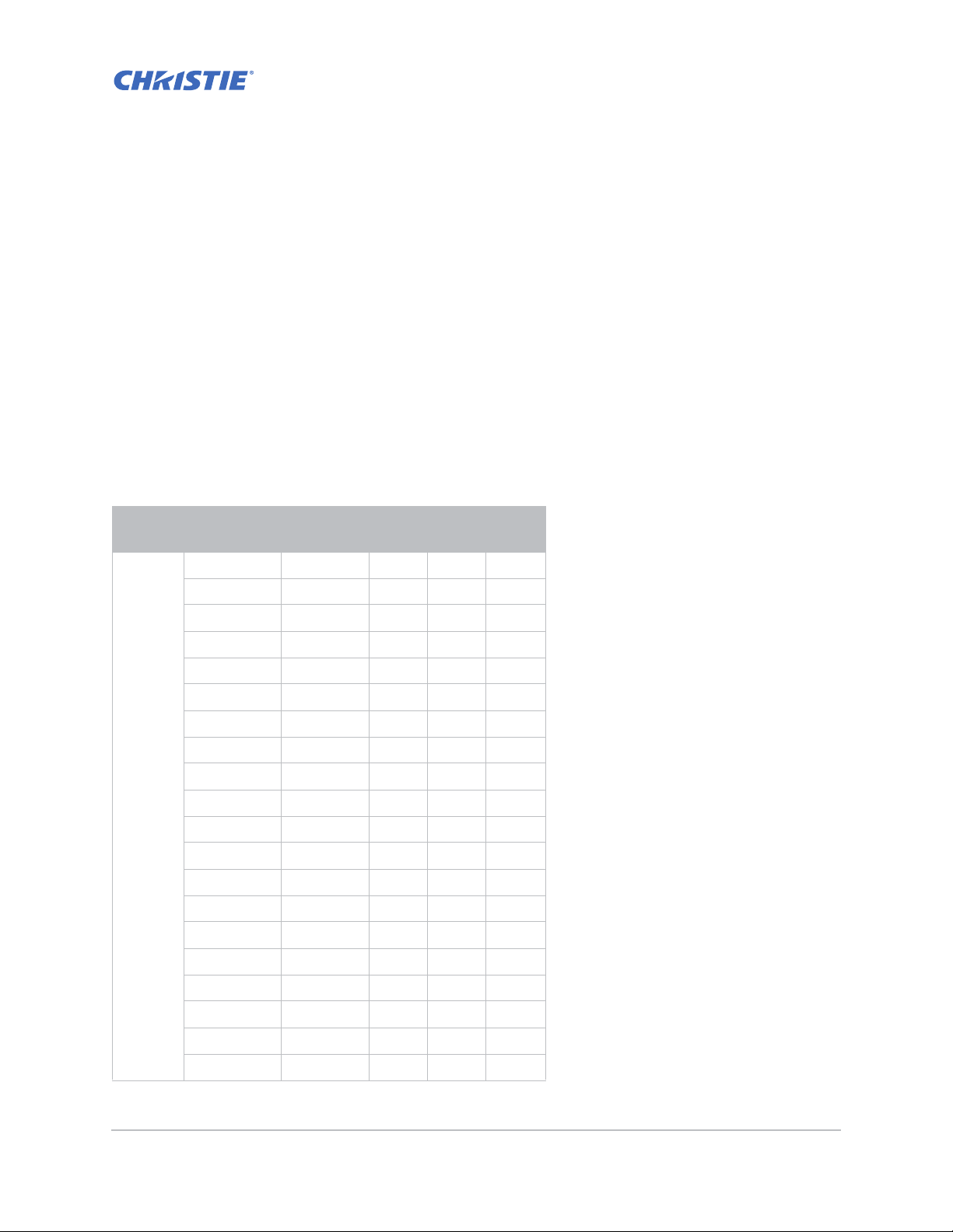
Specifications
Learn about the product specifications. Due to continuing research, specifications are subject to
change without notice.
Inputs
The following table details the inputs for GS Series. RB in the Resolution column indicates reduced
blanking.
Signal
Type
PC
Resolution
640x350 85 ●
640x400 85 ●●●
640x480 59 ●
640x480 60 ●●●
640x480 72 ●●●
640x480 75 ●●●
640x480 85 ●●●
720x400 85 ●●●
768x480 60 ●
768x480 75 ●
768x480 85 ●
800x600 50 ●
800x600 56 ●●●
800x600 60 ●●●
800x600 72 ●●●
800x600 75 ●●●
800x600 85 ●●●
848x480 50 ●
Frame
rate (Hz)
HDMI VGA DVI
848x480 60 ●
848x480 75 ●
GS Series 630-635 User Manual 70
020-001213-02 Rev. 1 (02-2018)
Page 71

Specifications
Signal
Type
Resolution
848x480 85 ●
960x600 50 ●
960x600 60 ●
960x600 75 ●
960x600 85 ●
1024x768 60 ●●●
1024x768 75 ●●●
1024x768 85 ●●●
1064x600 50 ●
1064x600 60 ●
1064x600 75 ●
1064x600 85 ●
1152x720 50 ●
1152x720 60 ●
1152x720 75 ●
1152x720 85 ●
Frame
rate (Hz)
HDMI VGA DVI
PC
1152x864 60 ●●●
1152x864 70 ●●●
1152x864 75 ●●●
1152x864 85 ●●●
1280x720 50 ●
1280x720 60 ●●●
1280x720 75 ●●●
1280x720 85 ●●●
1280x768 60 ●●●
1280x768 75 ●●●
1280x768 85 ●●●
1280x800 50 ●●●
1280x800 60 ●●●
1280x800 75 ●●●
1280x800 85 ●●●
1280x960 60 ●●●
1280x960 75 ●●●
1280x960 85 ●●●
GS Series 630-635 User Manual 71
020-001213-02 Rev. 1 (02-2018)
Page 72
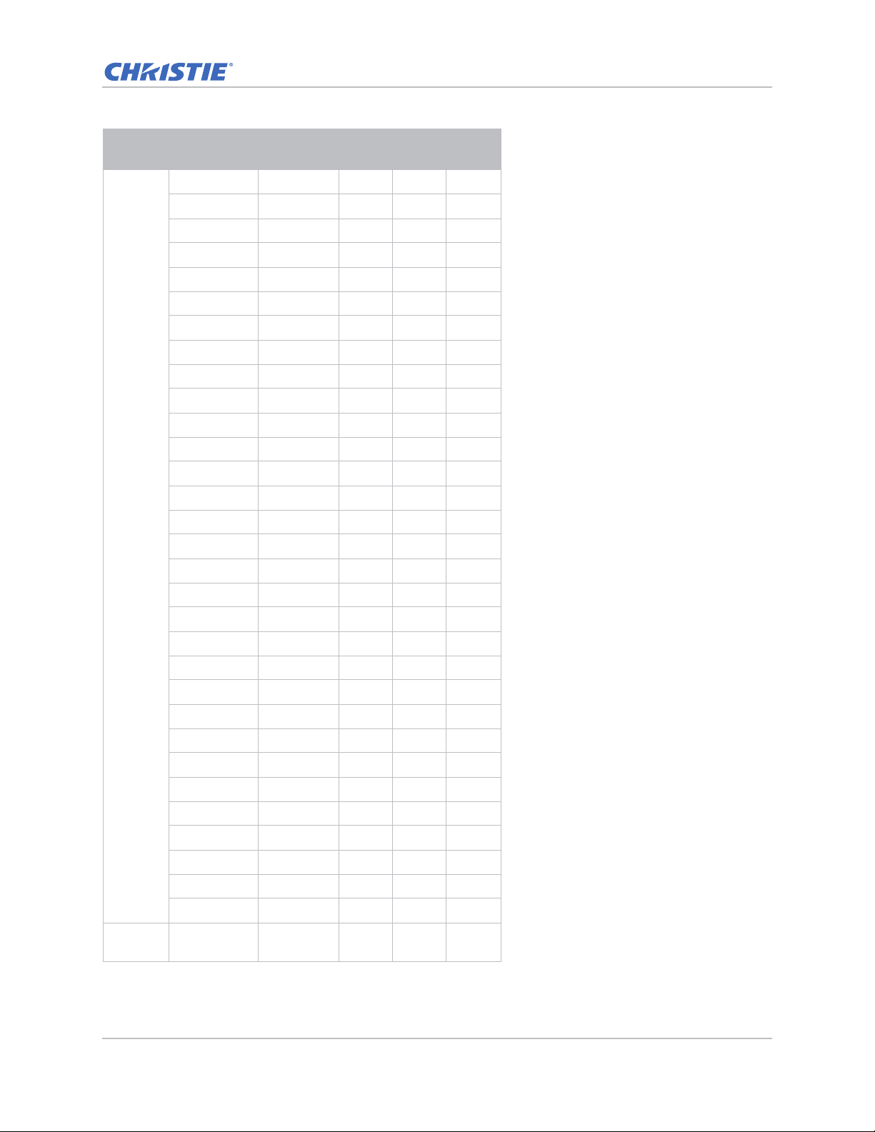
Specifications
Signal
Type
PC
Resolution
1280x1024 50 ●
1280x1024 60 ●●●
1280x1024 75 ●●●
1280x1024 85 ●●●
1360x768 50 ●
1360x768 60 ●
1360x768 75 ●
1360x768 85 ●
1366x768 60 ●●●
1400x900 60 ●●●
1400x1050 50 ●
1400x1050 60 ●●●
1400x1050 75 ●●●
1440x900 60 ●●●
1440x900 75 ●
1600x900 60 ●
Frame
rate (Hz)
HDMI VGA DVI
NTSC
1600x1200 50 ●
1600x1200 60 ●●●
1680x1050 50 ●
1680x1050 60 ●●●
1680x1050 75 ●
1704x960 50 ●
1704x960 60 ●
1728x1080 50 ●
1728x1080 60 ●
1864x1050 50 ●
1864x1050 60 ●
1920X1080 50 ●
1920X1080 60 ●● ●
1920X1200RB 60 ●●●
1920X1200RB 50 ●●●
NTSC (M,
4.43)
60
GS Series 630-635 User Manual 72
020-001213-02 Rev. 1 (02-2018)
Page 73

Specifications
Signal
Type
PAL
SECAM SECAM (M) 50
SDTV
EDTV
HDTV
Resolution
PAL (B,G,H,I) 50
PAL (N) 50
PAL (M) 60
480i 60 ●● ●
576i 50 ●● ●
480p 60 ●●●
576p 50 ●●●
1080i 25 ●● ●
1080i 29 ●● ●
1080i 30 ●● ●
720p 50 ●●●
720p 59 ●●●
720p 60 ●●●
1080s 23 ●
1080s 24 ●
1080p 23 ●●●
1080p 24 ●●●
1080p 25 ●●●
Frame
rate (Hz)
HDMI VGA DVI
1080p 29 ●●●
1080p 30 ●●●
1080p 50 ●●●
1080p 59 ●●●
1080p 60 ●●●
GS Series 630-635 User Manual 73
020-001213-02 Rev. 1 (02-2018)
Page 74
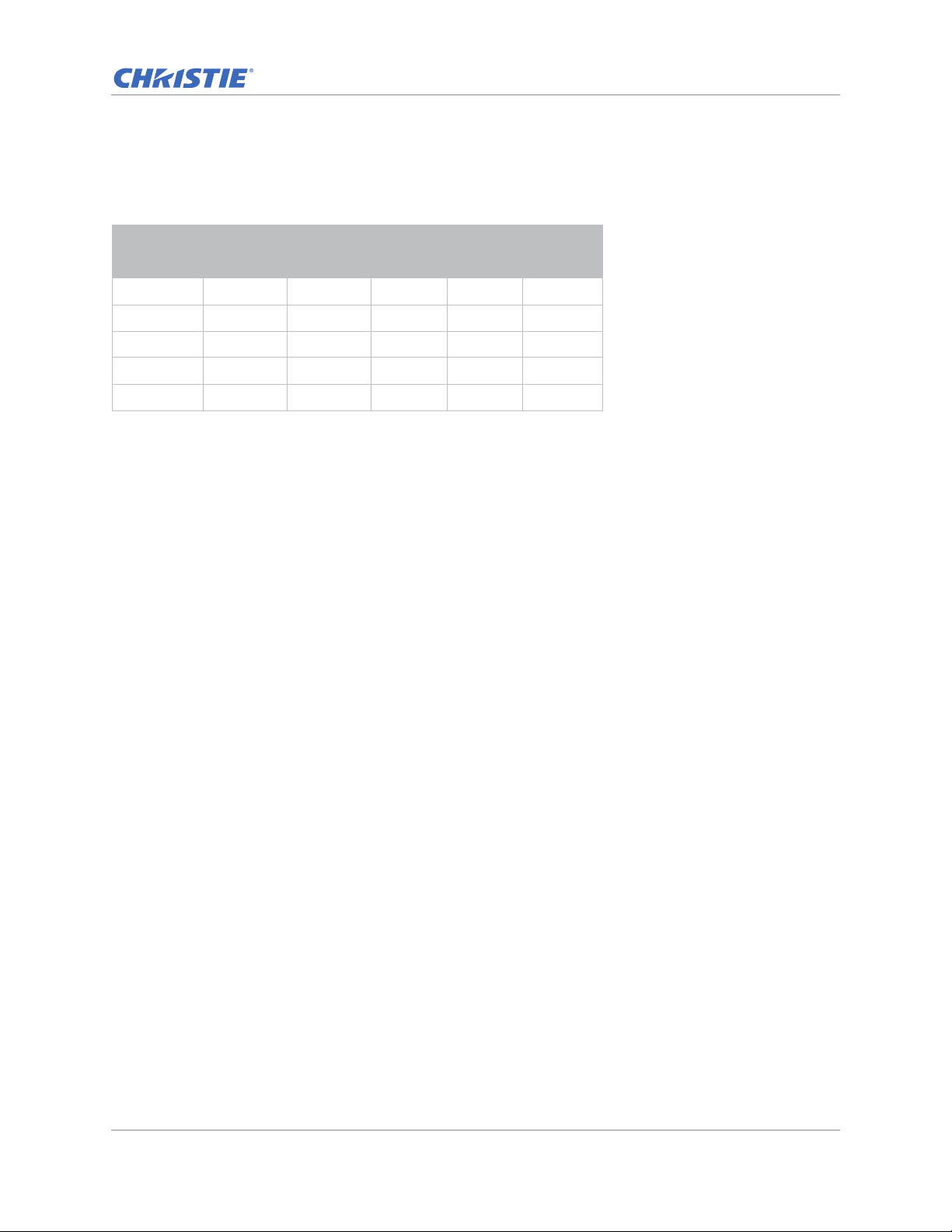
PIP/PBP compatibility
The following table details the PIP/PBP compatibility.
Specifications
PIP/PBP
VGA DVI-D HDMI-2 HDMI-1 HDBaseT
Matrix
VGA - ●●●●
DVI-D ● - ● -HDMI-2 ●●- ●●
HDMI-1 ● - ● -HDBaseT ● - ● --
•Dot (●): PIP/PBP combinations are enabled.
• Dash (-): PIP/PBP combinations are disabled.
GS Series 630-635 User Manual 74
020-001213-02 Rev. 1 (02-2018)
Page 75

Specifications
Key features
• HD 0.65" 1920 × 1080 resolution or WUXGA 0.67" 1920 × 1200 resolution
• Projection lens compatibility:
• Horizontal offset ranges: +/-30%
• Vertical offset ranges: +/-100% (WUXGA) and +/-120% (HD)
Measurements are based on industry standards where offset is calculated as a ratio of
the number of pixels shifted up/ down to half the image size.
• SNMP traps and email notifications
• 10-bit image processor electronics with modular design
• All video formats can be resized to full screen either horizontally or vertically while maintaining
aspect ratio
• The projector can be operated using any of the following:
• The built-in keypad, an infrared (IR) remote control, a wired remote control, a PC/device
using serial communications (Ethernet or RS232)
• A Web page via Ethernet
•Weight:
• Maximum product weight (with lens removed): 16.5 kg (36 lbs)
• Built-In keypad
GS Series 630-635 User Manual 75
020-001213-02 Rev. 1 (02-2018)
Page 76

Specifications
List of components
This projector comes with all the items listed below. Check to make sure your package is complete.
If anything is missing, contact your dealer.
• IR remote control (P/N: 003-004468-01)
• Power cords supplied with the projector:
• UK/Korea/Russia
•North America
•Europe
• Australia/New Zealand
• Japan
•India
•South Africa
•DVI to HDMI dongle
• User manual (USB)
Due to the difference in applications for each country, some regions may have different
accessories.
The following accessories are available for the projector:
• Cable Cover GS White (P/N: 140-106108-XX)
• Cable Cover GS Black (P/N: 140-106119-XX)
• Standard Lens 1.22 - 1.53 (P/N: 140-132107-XX)
• Optional Lens 0.95 - 1.22 (P/N: 140-101103-01)
• Optional Lens 1.52 - 2.89 (P/N: 140-102104-01)
• Optional Lens 0.75 - 0.95 (P/N: 140-119102-XX)
• Optional Lens 2.90 - 5.50 (P/N: 140-107109-XX)
• Optional Lens 1.22-1.52 (P/N: 140-131106-XX)
• Optional Lens 0.36 (P/N: 140-133108-XX)
• Christie One Mount (P/N: 108-506102-XX)
• One Mount Extender Rod (P/N: 121-125109-XX)
• One Mount Rigging Kit (P/N: 121-126100-XX)
GS Series 630-635 User Manual 76
020-001213-02 Rev. 1 (02-2018)
Page 77
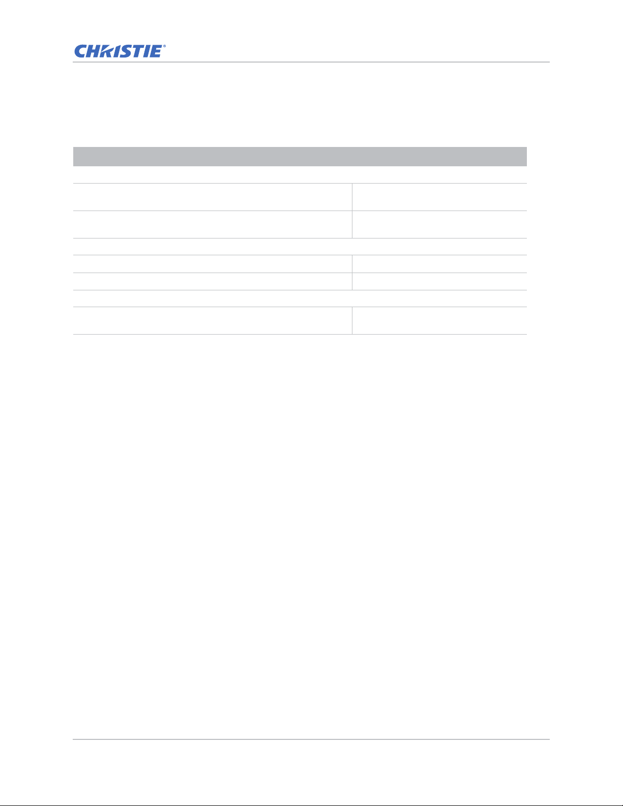
Physical specifications
Learn the dimensions and weight of the projector.
Description Dimensions
Projector size
Specifications
Overall size (L x W x H) (excluding lens, feet) 456 mm (18.0 in) x 505 mm (19.9 in) x
Overall size, shipping without lens (L x W x H) (includes
packaging)
Projector Weight
Without lens 16.5 kg (36 lbs)
Shipping without lens (includes packaging) 22.3 kg (49.2 lbs)
Operating position
360 degree front to back and portrait capable
190 mm (7.5 in)
596 mm (23.5 in) x 626 mm (24.6 in) x
341 mm (13.4 in)
Free orientation and no tilt range
constraint.
Physical operating environment
Provides specifications for the operating environment.
• Operating: 5°C to 40°C
• 5 to 40 degrees C (0 to 2500 ft)
• 5 to 35 degrees C (2500 to 5000 ft)
• 5 to 30 degrees C (5000 to 10000 ft)
• Storage temperature range: -10°C to 60°C
• Humidity range: 10% to 85% RH (maximum), non condensing
• Storage humidity range: 5% to 90% RH (maximum), non condensing
• Operating altitude: 10,000 ft maximum
GS Series 630-635 User Manual 77
020-001213-02 Rev. 1 (02-2018)
Page 78

Power requirements
Learn the power requirements for the projector.
Parameter Requirement
Rated voltage
Input 100-240V
Rated current
Input 7A
Line frequency 50/60Hz
AC input coupler
Inrush current 76A max
Maximum power consumption
Input 650W
Maximum power consumption, ECO mode
Input 470W
Maximum power consumption, WLAN mode
Specifications
Input < 8.0W
Maximum power consumption, Standby mode
Input < 0.5W
Regulatory
This product conforms to the following regulations related to product safety, environmental
requirements and electromagnetic compatibility (EMC).
Safety
• CSA C22.2 No. 60950-1
• UL 60950-1
• IEC 60950-1
• EN 60950-1
Laser Safety
• IEC 60825-1
• IEC 62471
• FDA CDRH CFR 1040.10
GS Series 630-635 User Manual 78
020-001213-02 Rev. 1 (02-2018)
Page 79

• FDA CDRH CFR 1040.11
Electro-Magnetic Compatibility
Emissions
• FCC CFR47, Part 15, Subpart B/ANSI C63.4, Class A - Unintentional Radiators
• CISPR32/EN55032 Class A - Information Technology Equipment
• ICES/NMB003 (A) - Information Technology Equipment
Immunity
• CISPR 24/EN55024 EMC Requirements - Information Technology Equipment
Environmental
• The product conforms to:
• EU Directive (2011/65/EU) on the restriction of the use of certain hazardous substances
(RoHS) in electrical and electronic equipment and the applicable official amendment(s).
Specifications
• EU Regulation (EC) No. 1907/2006 on the registration, evaluation, authorization and
restriction of chemicals (REACH) and the applicable official amendment(s).
• EU Directive (2012/19/EU) on waste and electrical and electronic equipment (WEEE) and
the applicable official amendment(s).
• China Ministry of Information Industry Order No.39 (02/2006) on the control of pollution
caused by electronic information products, the hazardous substances concentration limits
(SJ/T11363-2006), and the applicable product marking requirement (SJ/T11364-2006).
Marking
• This product conforms to all relevant Canadian, US, and European directives, standards, safety ,
health and environmental concerns. International packaging recycling marks conform to:
• EU Directive (2012/19/EU) on waste and electrical and electronic equipment (WEEE).
• EU Directive (94/62/EC) on packaging and packaging waste.
• China packaging recycling mark standard (GB18455-2001).
Federal Communications Commission (FCC) warning
• A shielded-type power cord is required in order to meet FCC emission limits and also to prevent
interference to the nearby radio and television reception. It is essential that only the supplied
power cord be used.
• Use only shielded signal cables to connect I/O devices to this equipment.
GS Series 630-635 User Manual 79
020-001213-02 Rev. 1 (02-2018)
Page 80
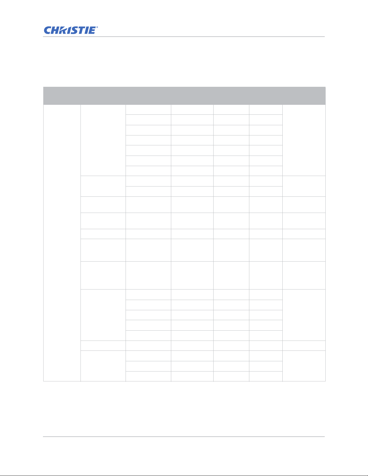
On-screen display tree
The following table provides the on-screen display menu.
Specifications
Level 1 Level 2
Picture Settings
Wall color White
Brightness 0 ~ 100 Depends on
Contrast 0 ~ 100 Depends on
Sharpness 0 ~ 10 5
Picture
Color 0 ~ 100 VGA
TINT 0 ~ 100 VGA
Level 3
(Or List)
Bright
Presentation
Film
REC709
Blending
DICOM SIM.
User
Gray 130
Video
Level 4
(Or List)
Level 5
(Or List)
Level 6
(Or List)
Default
Depends on
signal type.
White
color mode.
color mode.
component
signal only.
component
signal only
(white color).
Film
Gamma
White Peaking 0 ~ 100
Color Temp
GS Series 630-635 User Manual 80
020-001213-02 Rev. 1 (02-2018)
Bright
CRT
DICOM
Warm
Cool
Depend on
color mode.
BrightBright
Page 81
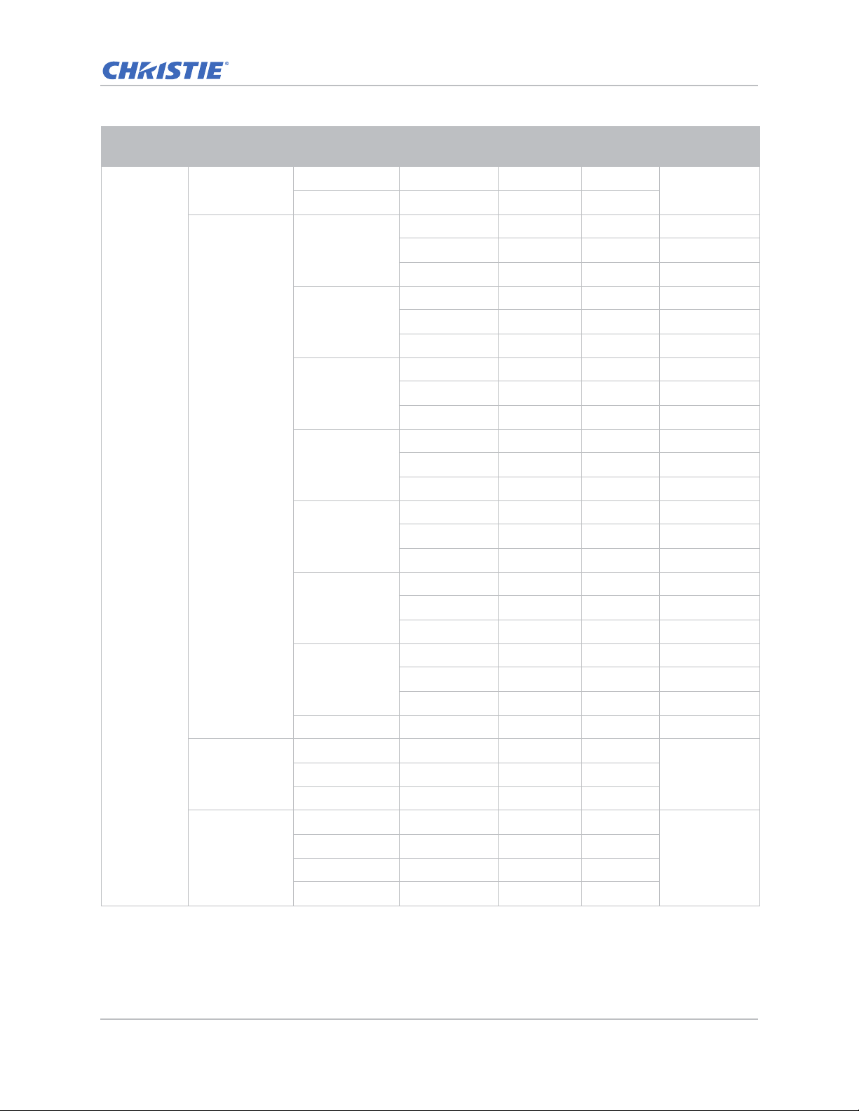
Specifications
Level 1 Level 2
Color Wheel
Speed
HSG Adjustment
Picture
Level 3
(Or List)
2X
3X
Red
Green
Blue
Cyan
Magenta
Level 4
(Or List)
Hue 1~199
Saturation 0 ~ 199
Gain 1 ~ 199
Hue 1~199
Saturation 0 ~ 199
Gain 1 ~ 199
Hue 1~199
Saturation 0 ~ 199
Gain 1 ~ 199
Hue 1~199
Saturation 0 ~ 199
Gain 1 ~ 199
Hue 1~199
Saturation 0 ~ 199
Level 5
(Or List)
Level 6
(Or List)
Default
3X
Contrast
Enhancement
Color Space
Yellow
White Gain
Reset to Default
Off
Real Black
Auto
RGB(0-255)
RGB(16-235)
YUV
Gain 1 ~ 199
Hue 1~199
Saturation 0 ~ 199
Gain 1 ~ 199
Red 1~199
Green 0 ~ 199
Blue 1 ~ 199
OffDynamic Black
Auto
GS Series 630-635 User Manual 81
020-001213-02 Rev. 1 (02-2018)
Page 82
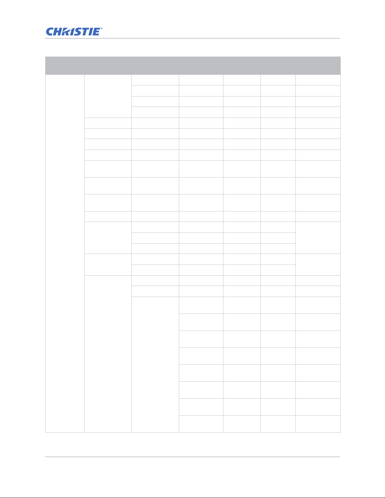
Specifications
Level 1 Level 2
Size Presets
Pixel Phase 0 ~ 100
Pixel Track 0 ~ 100
Horz Position 0 ~ 100
Vert Position 0 ~ 100
Digital Horz
Zoom
Digital Vert
Zoom
Digital Horz
Shift
Digital Vert Shift 0 ~ 100 50
Ceiling Mount
Screen
Rear Projection
Level 3
(Or List)
Auto
4:3
16:9
16:10
100% to 200% 0 ~ 10 0
100% to 200% 0 ~ 10 0
Off
Auto
Off
On
H. Keystone 0~40 20
V. Keystone 0~40 20
Level 4
(Or List)
0 ~ 100 50
Level 5
(Or List)
Level 6
(Or List)
Default
AutoOn
Off
Top Left Horz
Adjust
Top Left Vert
Adjust
Top Right Horz
Adjust
Geometric
Correction
4 Corners
GS Series 630-635 User Manual 82
020-001213-02 Rev. 1 (02-2018)
Top Right Vert
Adjust
Bottom Left
Horz Adjust
Bottom Left
Vert Adjust
Bottom Right
Horz Adjust
Bottom Right
Vert Adjust
Page 83
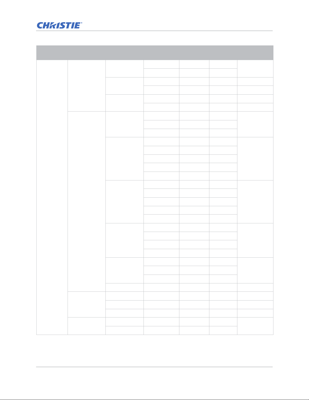
Specifications
Level 1 Level 2
Geometric
Correction
Screen
PIP-PBP
Settings
Level 3
(Or List)
Grid Color
Reset
PC Mode Off
Function
Main Source
Sub Source
Level 4
(Or List)
Purple
Green
Yes
No
On
Off
PIP
VGA
HDMI-1
HDMI-2
DVI
HDBaseT
VGA
HDMI-1
HDMI-2
DVI
HDBaseT
Level 5
(Or List)
Level 6
(Or List)
Default
Green
OffPBP
Current
Source.
Depends on
current source.
Top Left
Location
Size
Swap
Change Sources
Input key
Auto Image
GS Series 630-635 User Manual 83
020-001213-02 Rev. 1 (02-2018)
List all Sources
Auto Source
Normal
Wide
Top Right
Top Left
Bottom Left
Bottom Right
Small
MediumMedium
Large
Wide
Page 84
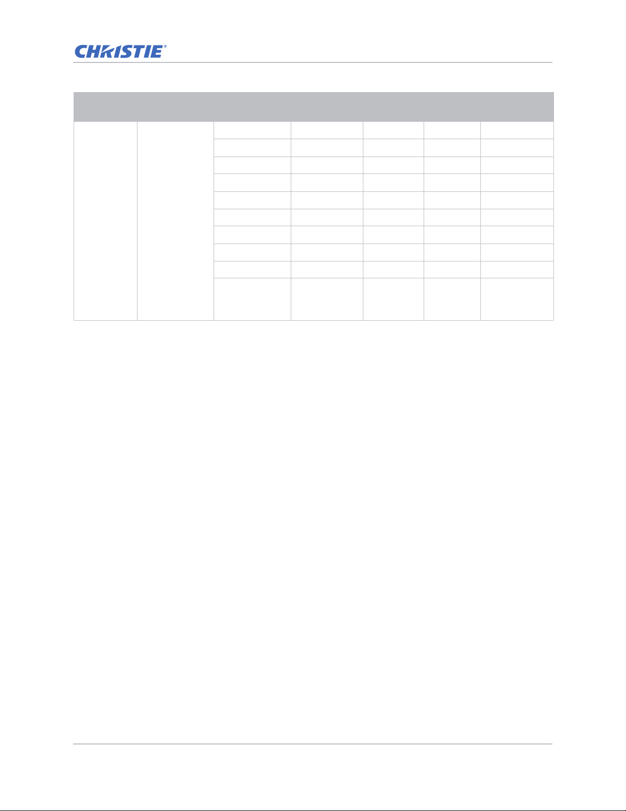
Specifications
Level 1 Level 2
Screen Source Info
Level 3
(Or List)
Active Source
Signal Format
Aspect Ratio
Resolution
Vert Refresh
Horz Refresh
Pixel Clock
Sync Type
Color Space
PIP/PBP
(When PIP/PBP
active)
Level 4
(Or List)
Level 5
(Or List)
Level 6
(Or List)
Default
GS Series 630-635 User Manual 84
020-001213-02 Rev. 1 (02-2018)
Page 85
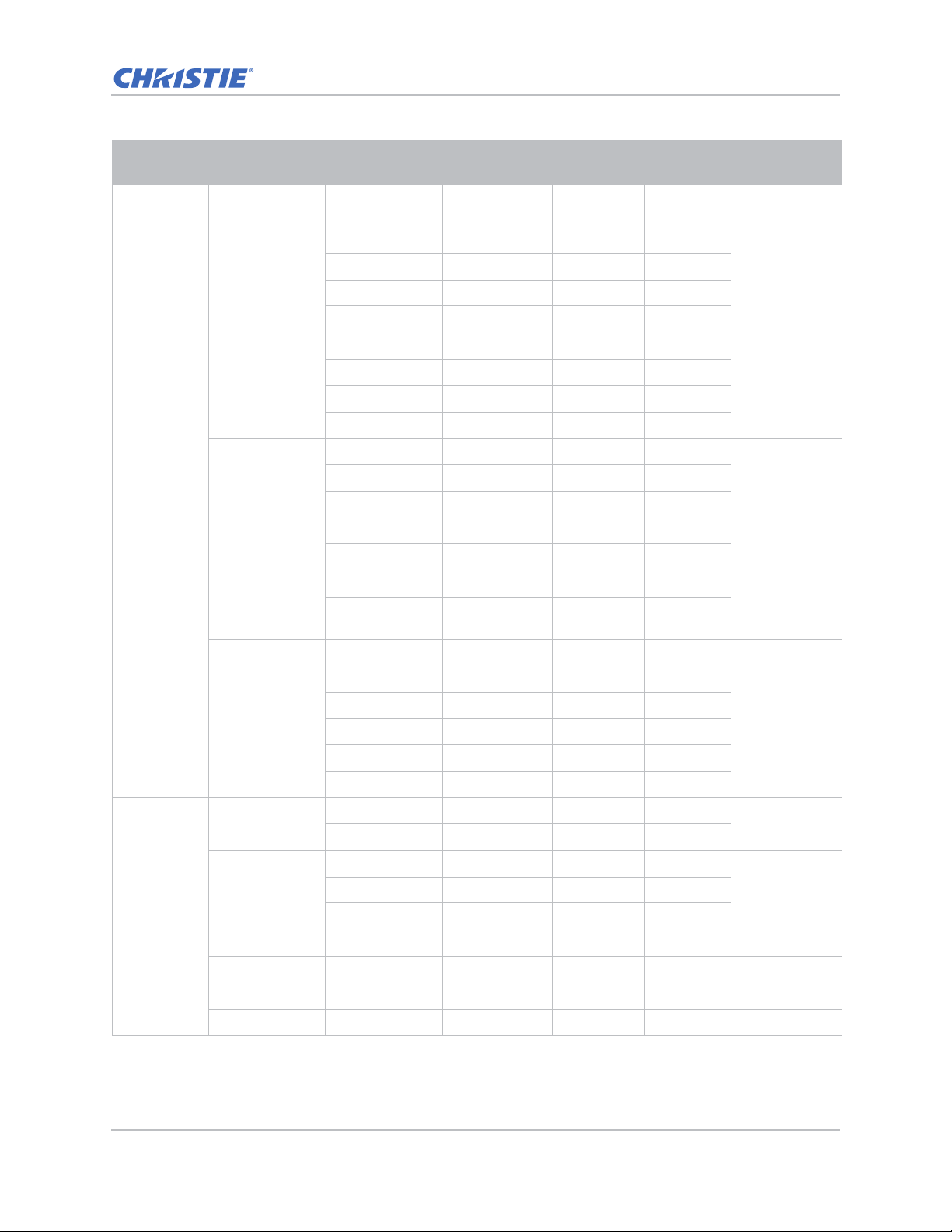
Specifications
Level 1 Level 2
Language
Settings
Menu Location
LAN (Standby)
Level 3
(Or List)
English 0
Simplified
Chinese 1
French 2
German 3
Italian 4
Japanese 5
Korean 6
Russian 7
Spanish 8
Left Top
Right Top
Center
Left Bottom
Right Bottom
0.5W mode
Communication
mode
None
Grid
Level 4
(Or List)
Level 5
(Or List)
Level 6
(Or List)
Default
English
Left Top
Communication
Test Pattern
Direct Power On
Settings
GS Series 630-635 User Manual 85
020-001213-02 Rev. 1 (02-2018)
Hot-Key settings
Reset to Default
Service
White
None
Black
Checkerboard
Color Bars
On
Off
Off
Blank Screen
Aspect Ratio
Blank Screen
Freeze Screen
Projector Info
Yes
No
Page 86
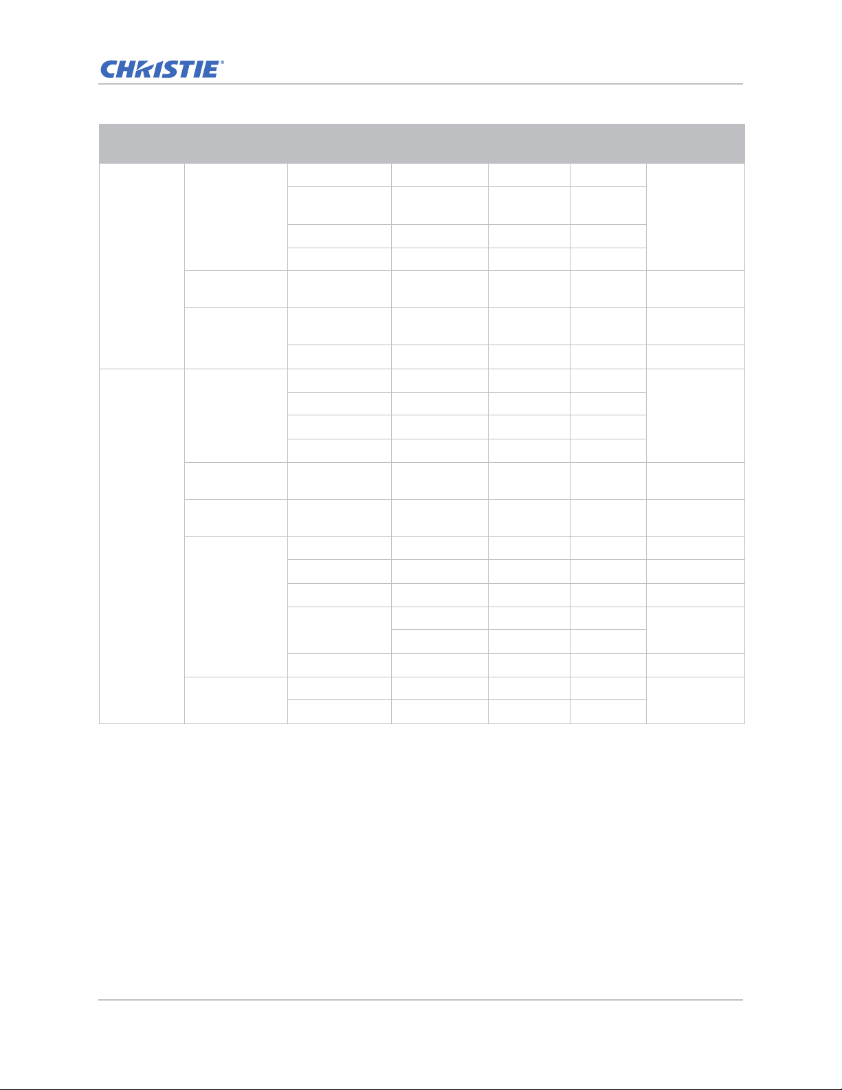
Specifications
Level 1 Level 2
Light Source
Mode
Light source
Constant Power 0 to 99 (30% to
Light Source
Info
Splash Screen
Auto shutdown 0~120 (one
Sleep Timer 0~990 (one
Options
Level 3
(Or List)
Constant Power
Constant
Intensity
ECO 1 (80%)
ECO 2 (50%)
100%)
Total Projector
Hours
LD Hours
Factory Logo
Blue
Black
White
step: 5 mins)
step: 10 mins )
Focus Command
Zoom Command
Level 4
(Or List)
Level 5
(Or List)
Level 6
(Or List)
Default
Constant Power
99
Default Value
0
0
Lens settings
High Altitude
Lens Shift Command
Allow
Lock lens motors
Locked
Lens calibration Command
On
Off
Allow
Off
GS Series 630-635 User Manual 86
020-001213-02 Rev. 1 (02-2018)
Page 87
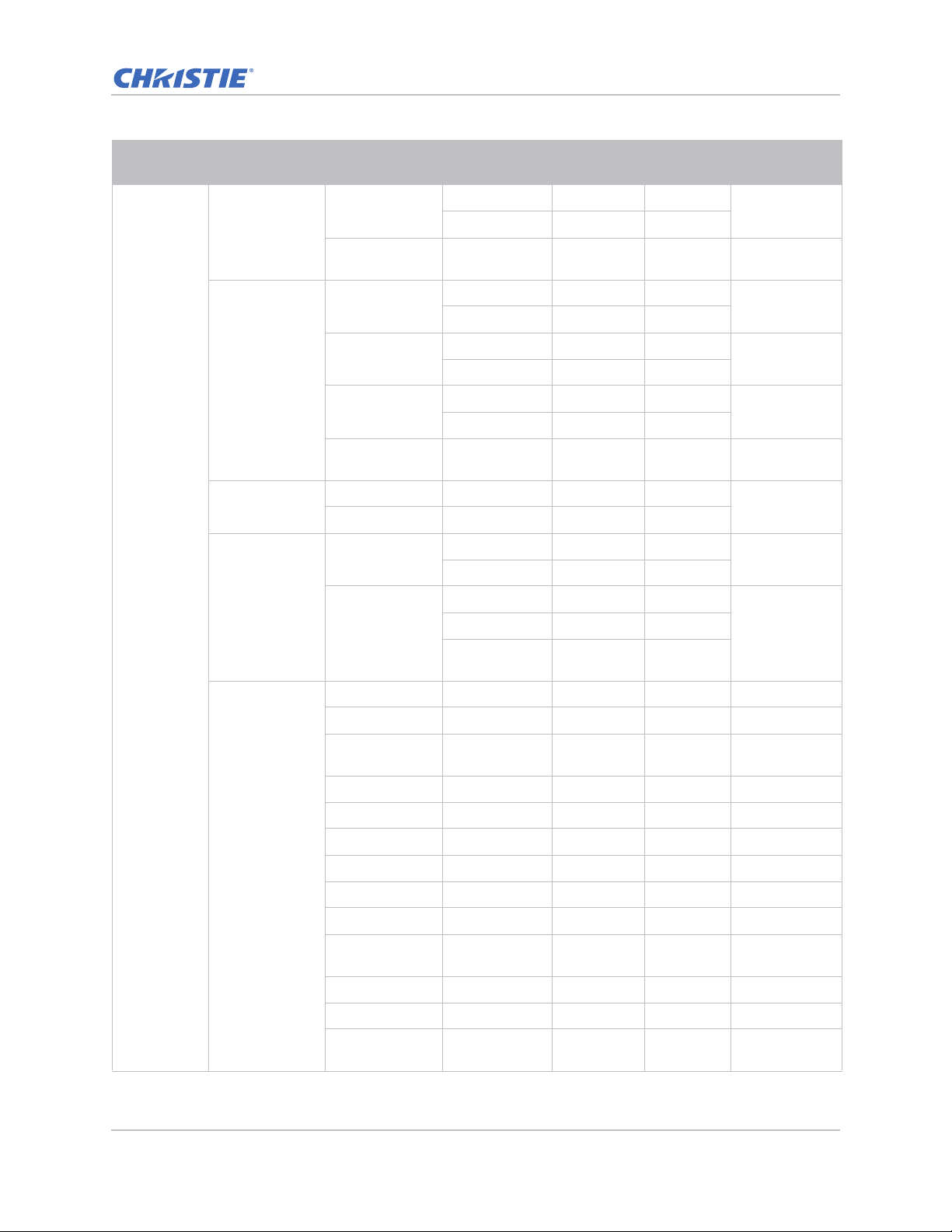
Specifications
Level 1 Level 2
PIN Protect
Remote Settings
Information
Hide
Backlight
Preferences
Options
Level 3
(Or List)
Security
Change
Password
Top
Front
HDBaseT
Projector
Address
On
Off
Keypad
Backlight
Status LED
Model Name
Serial Number
Level 4
(Or List)
On
Off
Off
On
Off
On
Off
On
0 ~ 9 0
Always On
Always Off
Always On
Always Off
Warning/Errors
only
Level 5
(Or List)
Level 6
(Or List)
Default
Off
On
On
On
Off
Always On
Always On
Native
Resolution
MCU FW
DDP FW
M9813 FW
Information
GS Series 630-635 User Manual 87
020-001213-02 Rev. 1 (02-2018)
Motor FW
PW808 FW
Main Input
Main Signal
Format
Main Pixel Clock
Main Sync Type
Main Horz
Refresh
Page 88
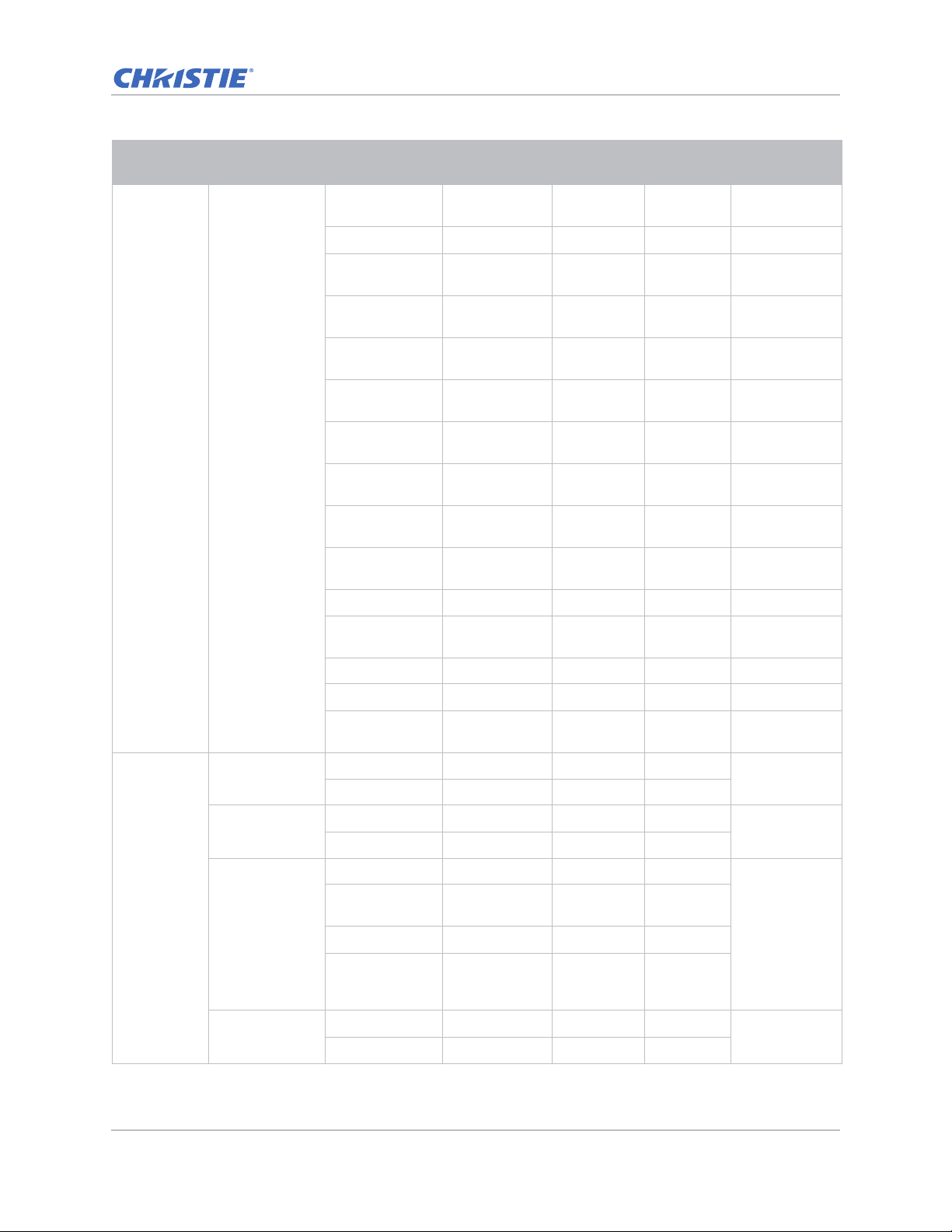
Specifications
Level 1 Level 2
Options Information
Level 3
(Or List)
Main Vert
Refresh
PIP/PBP Input
PIP/PBP Signal
Format
PIP/PBP Pixel
Clock
PIP/PBP Sync
Type
PIP/PBP Horz
Refresh
PIP/PBP Vert
Refresh
Light Source
Power
Total Projector
Hours
Light Source
Hours
Standby Mode
Lens Lock
Settings
IP Address
DHCP
Level 4
(Or List)
Level 5
(Or List)
Level 6
(Or List)
Default
System
Temperature
3D
3D Invert
3D
3D Format
1080p @ 24
GS Series 630-635 User Manual 88
020-001213-02 Rev. 1 (02-2018)
On
Auto
On
Off
Frame Packing Depends on
Side-by-Side
(Half)
Top and Bottom
Frame
Sequential (635GS)
96Hz
144Hz
Auto
Off
input signal. If
an HDMI
source with
AVINFO data
existed then
display 3D
mode
automatically.
144Hz
Page 89
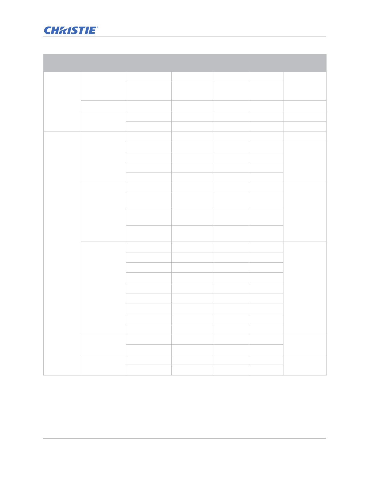
Specifications
Level 1 Level 2
3D
3D Sync Out
Frame Delay 1~ 200
L/R Reference
LAN
Network
Communicati
ons
Serial Port Baud
Rate
Level 3
(Or List)
To emitter
To Next
Projector
1st Frame
Field GPIO
DHCP
IP Address
Subnet Mask
Default Gateway
MAC Address
Projector Name
Show Network
Messages
Restart
Network…
Network Factory
Reset…
1200
2400
4800
9600
14400
19200
38400
Level 4
(Or List)
Level 5
(Or List)
Level 6
(Or List)
Default
To Emitter
By set
By set
115200
57600
115200
Serial Port Echo
Serial Port Path
GS Series 630-635 User Manual 89
020-001213-02 Rev. 1 (02-2018)
Off
Off
On
RS232
RS232
HDBaseT
Page 90
 Loading...