

Christie D4K25 CDXL-20, D4K25 CDXL-30, D4K25 CDXL-30SD, D4K35 CDXL-20, D4K35 CDXL-30 User Manual
...Page 1

D4K25
Section 1: Introduction
USER MANUAL
020-100882-02
CP4220 User Manual 1
020-100690-02 Rev. 1 July 6, 2012
Page 2

Page 3

D4K25
USER MANUAL
020-100882-02
Page 4

NOTICES
COPYRIGHT AND TRADEMARKS
© 2011 - 2012 Christie Digital Systems USA, Inc. All rights reserved.
All brand names and product names are trademarks, registered trademarks or trade names of their respective holders.
REGULATORY
The product has been tested and found to comply with the limits for a Class A digital device, pursuant to Part 15 of the FCC Rules. These limits
are designed to provide reasonable protection against harmful interference when the product is operated in a commercial environment. The
product generates, uses, and can radiate radio frequency energy and, if not installed and used in accordance with the instruction manual, may
cause harmful interference to radio communications. Operation of the product in a residential area is likely to cause harmful interference in which
case the user will be required to correct the interference at the user’s own expense.
This Class A digital apparatus complies with Canadian ICES-003.
Cet appareil numérique de la classe A est conforme à la norme NMB-003 du Canada.
㧊 ₆₆⓪ 㠛ⶊ㣿 (A ) 㦒⪲ 㩚㧦䕢㩗䞿❇⪳㦚 䞲 ₆₆㧊㡺┞ 䕦ⰺ㧦 ⡦⓪ ㌂㣿㧦⓪ 㧊㩦㦚 㭒㦮䞮㔲₆ ⧒Ⳇ , Ṗ㩫 㣎㦮 㰖㡃㠦㍲ ㌂㣿䞮⓪ ộ㦚
⳿㩗㦒⪲ 䞿┞┺ .
GENERAL
Every effort has been made to ensure accuracy, however in some cases changes in the products or availability could occur which may not be
reflected in this document. Christie reserves the right to make changes to specifications at any time without notice. Performance specifications
are typical, but may vary depending on conditions beyond Christie's control such as maintenance of the product in proper working conditions.
Performance specifications are based on information available at the time of printing. Christie makes no warranty of any kind with regard to this
material, including, but not limited to, implied warranties of fitness for a particular purpose. Christie will not be liable for errors contained herein
or for incidental or consequential damages in connection with the performance or use of this material.
The product is designed and manufactured with high-quality materials and components that can be recycled and reused. This symbol
means that electrical and electronic equipment, at their end-of-life, should be disposed of separately from regular waste. Please dispose of
the product appropriately and according to local regulations. In the European Union, there are separate collection systems for used
electrical and electronic products. Please help us to conserve the environment we live in!
Canadian manufacturing facility is ISO 9001 and 14001 certified.
GENERAL WARRANTY STATEMENTS
For complete information about Christie’s limited warranty, please contact your Christie dealer. In addition to the other limitations that may be
specified in Christie’s limited warranty, the warranty does not cover:
a. Damage occurring during shipment, in either direction.
b. Projector lamps (See Christie’s separate lamp program policy).
c. Damage caused by use of a projector lamp beyond the recommended lamp life, or use of a lamp supplied by a supplier other than Christie.
d. Problems caused by combination of the product with non-Christie equipment, such as distribution systems, cameras, video tape recorders,
etc., or use of the product with any non-Christie interface device.
e. Damage caused by misuse, improper power source, accident, fire, flood, lightening, earthquake or other natural disaster.
f. Damage caused by improper installation/alignment, or by product modification, if by other than a Christie authorized repair service
provider.
g. For LCD projectors, the warranty period specified applies only where the LCD projector is in “normal use.” “Normal use” means the LCD
projector is not used more than 8 hours a day, 5 days a week. For any LCD projector where “normal use” is exceeded, warranty coverage
under this warranty terminates after 6000 hours of operation.
h. Failure due to normal wear and tear.
PREVENTATIVE MAINTENANCE
Preventative maintenance is an important part of the continued and proper operation of your product. Please see the Maintenance section for
specific maintenance items as they relate to your product. Failure to perform maintenance as required, and in accordance with the maintenance
schedule specified by Christie, will void the warranty.
Page 5

Addendum
The CD included with this printed manual contains an electronic copy in English. Please read all instructions before
using or servicing this product.
㓚␛₼▔⚺䤓⏘䥧᧨サ㦘䧏₼㠖䤓䟄⓾㦻᧨∎䞷㒥冃≽㦻ℶ❐ⓜ᧨庆Ⅳ兕㩴梔㓏㦘䤓㖖䯉ᇭ
Le DC fourni avec ce manuel imprimé contient une copie électronique en français. S'il vous plaît lire toutes les
instructions avant d'utiliser ou de réparer ce produit.
Il CD fornito con il manuale stampato contiene una copia elettronica in lingua italiano. Si prega di leggere tutte le
istruzioni prima di utilizzare o riparare questo prodotto.
Ʌɠᤅɇɾɑ˃ʰˊʇːɝҨዸɇɾɘȼɼɰɋ "# ɝɡơෙཙౘəɠ᭴ᠦႚȾᮭɕɘȼɼɰɋƢɅɠ༎
үʄẖᄭȴɽȶɡጞࣟዟɇɾɽၿɝơɆᤈጷṫɇȶƢ
ꎙ鰩꽱隱뼝颍붡뼝鷍꽩넽鱉&' 꾅鱉뼑鞵ꈑ鷑놹녅ꩡꚭ냹붡뼝뼍隕넽걪鱽鲙 ꚭ뇑븽냹ꩡ끞뿮냵
ꟹ걙뼍韥놹꾅ꑝ麕덵렝ꩡ뼢麙냹넲꽩ꚩ겑韥ꗉꅂ鱽鲙
&'
El DC incluido con este manual impreso contiene una copia electrónica en español. Por favor, lea todas las
instrucciones antes de usar o dar servicio a este producto.
Page 6

Page 7

Table of Contents
1: Introduction
1.1 Labels and Markings ...................................................................................................................1-1
1.2 AC / Power Precautions...............................................................................................................1-2
1.3 Lamp Precautions ........................................................................................................................1-2
1.4 Contact Your Dealer....................................................................................................................1-3
2: Installation and Setup
2.1 Site Requirements........................................................................................................................2-1
2.2 Tools Required for Installation....................................................................................................2-1
2.3 Projector Components .................................................................................................................2-2
2.4 Installation Safety and Warning Guidelines................................................................................2-5
2.5 Position the Projector...................................................................................................................2-5
2.6 Adjust Tilt and Level the Projector .............................................................................................2-6
2.7 Install the Touch Panel Controller (TPC)....................................................................................2-7
2.8 Connect External Exhaust Ducting..............................................................................................2-8
2.8.1 Determine the Projector Exhaust CFM Value .....................................................................2-8
2.9 Remove the Shroud
................................................................................................................................2-9
2.10 Install the Primary Lens.............................................................................................................2-9
2.11 Install the Optional Anamorphic Lens.......................................................................................2-12
2.12 Install the Optional Wide Converter Lens.................................................................................2-12
2.13 Install the Lamp .........................................................................................................................2-13
2.14 Connect the Projector to AC Power with a Permanent Connection ..........................................2-14
2.15 Connect the Projector to AC Power with a Pluggable Type B Connection ..............................2-16
2.16 Configure the Optional Uninterrupted Power Supply ...............................................................2-17
2.17 Connect Sources and Turn the Projector On .............................................................................2-17
3: Connect Devices to the Projector
3.1 Connect a Computer or Server ....................................................................................................3-3
3.2 Connect Devices to the SCCI Port ..............................................................................................3-4
3.3 Connect Devices to the GPIO Port ..............................................................................................3-5
3.4 Connect Devices to the 3D Connector ........................................................................................3-7
4: Adjust the Image
4.1 Maximize Light Output ...............................................................................................................4-1
4.2 Calibrate Screen Brightness (fL) .................................................................................................4-1
4.3 Basic Image Alignment ...............................................................................................................4-1
4.4 Adjust Offset................................................................................................................................4-2
4.5 Adjust Offset with an ILS............................................................................................................4-2
4.6 Adjust Left and Right Boresight..................................................................................................4-2
4.7 Adjust Top and Bottom Boresight...............................................................................................4-4
4.8 Adjust Top and Bottom Boresight with an ILS...........................................................................4-5
4.9 Adjust DMD Convergence ..........................................................................................................4-5
4.10 Fold Mirror Adjustment.............................................................................................................4-6
4.11 Calibrating the System...............................................................................................................4-6
4.12 Color Calibration .......................................................................................................................4-7
D4K25 User Manual i
020-100882-02 Rev. 1 (07-2012)
Page 8

Table of Contents
4.13 Electronic Screen Masking .......................................................................................................4-7
5: Projector Operation
5.1 Turn the Projector On ..................................................................................................................5-1
5.2 Turn the Projector Off..................................................................................................................5-1
5.3 Projector Power States .................................................................................................................5-1
5.4 Projector LED Status Indicators ..................................................................................................5-2
5.5 Work with the Lamp ....................................................................................................................5-2
5.5.1 Turning the Lamp On...........................................................................................................5-2
5.5.2 Turn the Lamp Off ...............................................................................................................5-2
5.5.3 Adjust Lamp Power .............................................................................................................5-2
5.5.4 Change the Lamp Power Percentage ...................................................................................5-3
5.5.5 Use LampLOC™ to Adjust the Lamp Position ...................................................................5-3
5.5.6 Manually Adjust the Lamp Position ....................................................................................5-3
5.5.7 View Lamp Information.......................................................................................................5-3
5.5.8 Receive an Alarm when a Lamp Reaches Its Expiry Date ..................................................5-3
5.5.9 Receive an Alarm when a Lamp Needs to be Rotated.........................................................5-4
5.5.10 Lamp Expiry Hours............................................................................................................5-4
5.5.11 Minimum and Maximum Lamp Power Ratings ................................................................5-4
5.6 Work with Lenses ........................................................................................................................5-4
5.6.1 Enable Automatic ILS Selected ...........................................................................................5-5
5.6.2 Enable Automatic ILS NOT Selected..................................................................................5-5
5.6.3 Access the ILS .....................................................................................................................5-6
5.6.4 Enable ILS on a Channel .....................................................................................................5-6
5.6.5 Alter the Active ILS Settings ...............................................................................................5-6
5.6.6 Maintain Lens Position Regardless of Selected Channel.....................................................5-6
5.6.7 Reset the ILS........................................................................................................................5-7
5.6.8 Calibrate the ILS ..................................................................................................................5-7
5.7 Display Content ...........................................................................................................................5-7
5.8 Selecting a Source.......................................................................................................................5-7
6: Projector Menus
6.1 Using the Touch Panel Controller (TPC).....................................................................................6-1
6.2 Main Screen .................................................................................................................................6-2
6.3 Open the On Screen Keyboard ....................................................................................................6-4
6.4 User Access and Rights ...............................................................................................................6-4
6.5 Status Window.............................................................................................................................6-5
6.6 Alarm Window.............................................................................................................................6-10
6.7 Interrogator Window....................................................................................................................6-10
6.8 SMPTE Errors Window...............................................................................................................6-12
6.9 System Logs Window..................................................................................................................6-13
6.10 Server Test Window ..................................................................................................................6-14
6.11 DLP Management Window .......................................................................................................6-15
6.12 Network Devices........................................................................................................................6-16
6.13 Channel Setup Windows............................................................................................................6-16
ii D4K25 User Manual
020-100882-02 Rev. 1 (07-2012)
Page 9

Table of Contents
6.13.1 Config 1 Window...............................................................................................................6-17
6.13.2 Config 2 Window...............................................................................................................6-18
6.13.3 3D Control Window...........................................................................................................6-19
6.14 Advanced Setup Windows.........................................................................................................6-22
6.14.1 Lamp Power / LiteLOC™ Setup Window........................................................................6-23
6.14.2 Lamp History Window ......................................................................................................6-24
6.14.3 LampLOC™ Setup Window .............................................................................................6-25
6.14.4 Advanced Setup: ILS File Setup Window.........................................................................6-27
6.14.5 Lens Setup Window...........................................................................................................6-28
6.14.6 Source File Setup Window ................................................................................................6-29
6.14.7 Screen File Setup Window ................................................................................................6-29
6.14.8 MCGD File Setup Window ...............................................................................................6-31
6.14.9 TCGD File Setup Window ................................................................................................6-32
6.15 Administrator Setup Window....................................................................................................6-33
6.15.1 Preferred Channel Setup Window .....................................................................................6-33
6.15.2 Preferred Test Pattern Setup Window ...............................................................................6-34
6.15.3 Preferences Window ..........................................................................................................6-35
6.15.4 Scheduler Window.............................................................................................................6-37
6.15.5 Communications Configuration Window..........................................................................6-38
6.15.6 GPIO Setup Window .........................................................................................................6-40
6.15.7 Foot Lamberts Calibration Window ..................................................................................6-41
6.15.8 User Accounts Window .....................................................................................................6-41
6.15.9 Upgrade Window...............................................................................................................6-44
6.16 Service Setup .............................................................................................................................6-45
6.16.1 Service Setup: File Management Window ........................................................................6-46
6.16.2 Digital Convergence Window ...........................................................................................6-46
6.16.3 System Access Window.....................................................................................................6-48
6.16.4 Service Setup: Lamp Power Supply ..................................................................................6-49
6.17 About Window .........................................................................................................................6-49
6.17.1 Help Window....................................................................................................................6-50
7: Maintenance
7.1 Inspect Ventilation.......................................................................................................................7-1
7.2 Fill the Coolant Reservoir............................................................................................................7-1
7.3 Inspect the Lamp .........................................................................................................................7-1
7.4 Inspect and Clean Optics .............................................................................................................7-2
7.4.1 Clean the Lens .....................................................................................................................7-2
7.5 Inspect and Clean the Lamp Blower............................................................................................7-2
7.6 Clean the Igniter ..........................................................................................................................7-3
7.7 Inspect and Clean the Airflow Interlocks ....................................................................................7-3
7.8 Inspect the Laminar Airflow Device (LAD) ...............................................................................7-3
7.9 Replace the Lamp ........................................................................................................................7-3
7.10 Rotate the Lamp.........................................................................................................................7-6
7.11 Replace the Light Engine Air Filter ..........................................................................................7-6
7.12 Replace the Liquid Cooling Air Filter.......................................................................................7-7
7.13 Replace the Lens........................................................................................................................7-7
D4K25 User Manual iii
020-100882-02 Rev. 1 (07-2012)
Page 10

Table of Contents
8: Troubleshooting
8.1 Projector Does Not Turn On........................................................................................................8-1
8.2 Lamp Does Not Ignite..................................................................................................................8-1
8.3 Lamp Suddenly Turns Off ...........................................................................................................8-2
8.4 Flicker, Shadows, Or Dimness.....................................................................................................8-2
8.5 LampLOC™ Not Working .........................................................................................................8-2
8.6 LiteLOC™ Not Working.............................................................................................................8-2
8.7 Touch Panel Controller (TPC).....................................................................................................8-3
8.8 Trouble Establishing Communication with Projector..................................................................8-3
8.9 Blank Screen, No Display of Image ............................................................................................8-3
8.10 Image Appears Vertically Stretched or ‘Squeezed’ into Center of Screen................................8-3
8.11 Inaccurate Display Colors..........................................................................................................8-3
8.12 Display is Not Rectangular .......................................................................................................8-3
8.13 Display is Noisy........................................................................................................................8-4
8.14 Display has Suddenly Frozen.....................................................................................................8-4
8.15 Data is Cropped from Edges......................................................................................................8-4
8.16 The Projector is ON, but There is No Image ............................................................................8-4
8.17 The Display is Jittery or Unstable..............................................................................................8-4
8.18 The Display is Faint...................................................................................................................8-4
8.19 Portions of the Display are Cut OFF or Warped to the Opposite Edge....................................8-5
8.20 Display Appears Compressed (Vertically Stretched) ...............................................................8-5
8.21 Inconsistent Picture Quality......................................................................................................8-5
A: Specifications
A.1 Display ........................................................................................................................................A-1
A.1.1 Panel Resolution and Refresh Rate .....................................................................................A-1
A.1.2 Achievable Brightness (Measured at Screen Center)..........................................................A-1
A.1.3 Achievable Contrast Ratio ..................................................................................................A-1
A.1.4 Color and Gray Scale ..........................................................................................................A-1
A.1.5 White Point..........................................................................................................................A-1
A.1.6 Gamma ................................................................................................................................A-1
A.2 Source Signal Compatibility .......................................................................................................A-1
A.3 Control Signal Compatibility......................................................................................................A-4
A.3.1 Ethernet Port........................................................................................................................A-4
A.3.2 RS232-PIB3G .....................................................................................................................A-4
A.3.3 RS232-ICP ..........................................................................................................................A-4
A.3.4 GPIO Port............................................................................................................................A-4
A.3.5 Simple Contact Closure Interface (SCCI) Port ...................................................................A-5
A.4 Touch Panel Controller ...............................................................................................................A-5
A.5 Power Requirements ...................................................................................................................A-6
A.5.1 AC Input..............................................................................................................................A-6
A.5.2 UPS AC Input .....................................................................................................................A-6
A.6 Lamp ...........................................................................................................................................A-6
A.7 Physical Specifications ...............................................................................................................A-7
A.8 Regulatory...................................................................................................................................A-7
iv D4K25 User Manual
020-100882-02 Rev. 1 (07-2012)
Page 11

Table of Contents
A.8.1 Safety ..................................................................................................................................A-7
A.8.2 Electro-Magnetic Compatibility .........................................................................................A-7
A.9 Environment ...............................................................................................................................A-8
A.9.1 Operating Environment.......................................................................................................A-8
A.9.2 Non-Operating Environment ..............................................................................................A-8
A.10 Accessories ...............................................................................................................................A-8
A.10.1 Standard (sold with product)............................................................................................A-8
A.10.2 Accessories (sold separately)...........................................................................................A-9
B: Serial API
B.1 Function Codes ..........................................................................................................................B-1
D4K25 User Manual v
020-100882-02 Rev. 1 (07-2012)
Page 12

Page 13
1 Introduction
DANGER
WARNING
WARNING
WARNING
WARNING
This manual is intended for professionally trained operators of Christie high-brightness projection systems.
These operators are qualified to replace the lamp and air filter, but should not attempt to install or service the
projector.
Only accredited Christie technicians who are knowledgeable about the hazards associated with high-voltage,
ultraviolet exposure, and the high temperatures generated by the projector lamp are authorized to assemble,
install, and service the projector.
1.1 Labels and Markings
These warning labels can appear on the projector:
Indicates a hazardous situation which that could result in death or serious injury.
Indicates a hazardous situation which, if not avoided, could result in death or
serious injury.
Indicates a hazardous situation that could result in minor or moderate injury.
NOTICE! Addresses practices not related to personal injury.
Never look directly into the projector lens or at the lamp. The extremely high
brightness can cause permanent eye damage. For protection from ultraviolet radiation, keep
all projector housings intact during operation. Protective safety gear and safety goggles are
recommended when servicing.
FIRE HAZARD! Keep hands, clothes, and all combustible material away from
the concentrated light beam of the lamp.
Position all cables where they cannot contact hot surfaces or be
pulled or tripped over.
1) The American Conference of Governmental Industrial Hygienists
(ACGIH) recommends occupational UV exposure for an 8-hour day to be less than 0.1
microwatts per square centimeters of effective UV radiation. An evaluation of your workplace
is advised to assure employees are not exposed to cumulative radiation levels exceeding the
government guidelines for your area. 2) Be aware that some medications are known to
increase sensitivity to UV radiation.
D4K25 User Manual 1-1
020-100882-02 Rev. 1 (07-2012)
Page 14

Section 1: Introduction
WARNING
WARNING
DANGER
DANGER
1.2 AC / Power Precautions
To correctly install this projector, a certified electrician must install a permanent a single-phase connection
from the projector to the AC supply. You must operate the projector at the recommended voltage.
1) Disconnect projector from AC before opening any enclosure.
2) High leakage current. Earth connection essential before connecting supply.
1) DO NOT allow anything to rest on the power cord. Locate the projector where the cord
cannot be damaged by people walking on it or by objects rolling over it. Never operate the
projector if the power cable appears damaged in any way.
2) DO NOT overload power outlets and extension cords as this can result in fire or shock
hazards.
3) Note that only qualified service technicians are permitted to open any enclosure on the
product and only if the AC has been fully disconnected from the product.
Power Cords and Attachments
1) The North American rated line cord is provided with each projector. Ensure
that you are using a power cord, socket and power plug that meets the appropriate local
rating standards. 2) Use only an AC power cord recommended by Christie. Do not attempt
operation if the AC supply and cord are not within the specified voltage and power range.
Use only the attachments and/or accessories recommended by Christie. Use of others may result in the risk of
fire, shock or personal injury.
1.3 Lamp Precautions
Lamps used in the projector are under high pressure and you must handle them with caution. Lamps can
explode and cause serious personal injury if they are dropped or mishandled.
EXPLOSION HAZARD! Wear authorized protective safety clothing whenever the lamp
door is open.
Recommended protective clothing includes, but may not be limited to a polycarbonate face shield,
protective gloves, and a quilted ballistic nylon jacket or a welder’s jacket. This equipment is included in
included in the Christie Protective Clothing Safety Kit #598900-095.
NOTE: Christie’s protective clothing recommendations are subject to change. Any local or federal specifica-
tions take precedence over Christie recommendations.
Lamp may explode causing bodily harm or death. 1) Always wear protective
clothing whenever lamp door is open or while handling lamp. 2) Verify those within the
vicinity of the projector are also suited with protective clothing. 3) Never attempt to access
the lamp while the lamp is on. Wait at least 10 minutes after the lamp turns OFF before
powering down, disconnecting from AC and opening the lamp door.
The arc lamp operates at a high pressure that increases with temperature. Failure to allow the
lamp to sufficiently cool prior to handling increases the potential for an explosion causing
personal injury or property damage.
1-2 D4K25 User Manual
020-100882-02 Rev. 1 (07-2012)
Page 15

1.4 Contact Your Dealer
If you encounter a problem with your Christie projector, contact your dealer. To assist with the servicing of
your projector, enter the information in the tables and keep this information with your records.
Table 1.1 Purchase Record
Dealer:
Dealer or Christie Sales/Service Contact Phone Number:
Projector Serial Number*:
Purchase Date:
Installation Date:
* The serial number is on the license label located on the front panel of the projector.
Table 1.2 Ethernet Settings
Default Gateway
Projector IP Address
Subnet Mask
Section 1: Introduction
D4K25 User Manual 1-3
020-100882-02 Rev. 1 (07-2012)
Page 16

Page 17

2 Installation and Setup
This section explains how to install, connect, and optimize the projector display.
2.1 Site Requirements
To safely install and operate the D4K25 projector, the installation location must meet these minimum
requirements:
• Physical Operating Environment
• Maximum Ambient Temperature (operating) 35°C
• Minimum Ambient Temperature (operating) 10°C
• External Exhaust Ducting
• The installation site must provide a minimum of 450 CFM (ft
adequate cooling of the Xenon arc lamp at less than or equal to 25°C ambient and less than 3,000 feet elevation. Above 25°C or 3,000 feet, 600 CFM is required. For detailed instructions for measuring CFM, see
2.8 Connect External Exhaust Ducting, on page 2-8.
• Permanent Power Connection
• A 30A maximum double pole, UL listed wall circuit breaker is required. It must be part of the building
installation and easily accessible.
3
/min) external exhaust airflow to ensure
• Single-phase projector unit: Maximum 15A circuit breaker protection provided as part of the building
installation
• Protection from overcurrents, short circuits, and earth faults must be part of the building installation.
• Protection from overcurrents, short circuits, and earth faults must be part of the building installation. The
disconnect device (double pole switch or circuit breaker with minimum 3mm contact gap) must be readily
accessible within the projection room.
• This product can be connected to an IT power distribution system.
2.2 Tools Required for Installation
You need these tools to install the D4K25 projector:
• 12” screwdrivers: Phillips #2 (magnetic) and flat
• 19mm and 7/8” wrenches
• Assorted Allen keys (metric)
• Heat extractor
• Christie approved protective safety clothing if you are working with the lamp
• Lamp
• Lens cleaning tissue and solution
D4K25 User Manual 2-1
020-100882-02 Rev. 1 (07-2012)
Page 18

Section 2: Installation and Setup
2.3 Projector Components
Figure 2-1 Projector Overview
Air Filter Cover and Air Filter
The air filter filters the intake air before it circulates in the front compartment to cool the main electronics. See
Section 7.11 Replace the Light Engine Air Filter.
Manual Douser Override
Closes the douser. Closing the douser rotates a shutter blade in front of the lamp and reduces lamp power to
2kW to conserve lamp life. The override switch is meant for emergency use only.
Exhaust Duct and Vane Switch
Extracts heated air from the lamp compartment. The vane switch inside the rigid port monitors the amount of
airflow. See Section 2.1 Site Requirements for airflow requirements of the external heat extraction system.
Adjustable Feet
Adjusts the tilting angle of the projector.
2-2 D4K25 User Manual
020-100882-02 Rev. 1 (07-2012)
Page 19

Section 2: Installation and Setup
Lamp Door and Lamps
Provides access to the lamp. The lamp door must remain closed and locked for normal operation. Lamp
replacement should only be performed by qualified technicians.
The projector is designed to operate with 2.0kW, or 3.0kW lamps. See Section Appendix A: Specifications for a
complete list of available lamp types.
LED Status Indicators
Provides information about the status of the projector. See Section 5 Projector Operation for information about
projector status
Projection Lens
A variety of lenses can be used with the D4K25 projector. See Section Appendix A: Specifications for a list of
available lenses.
RS-422 Connector
Connects the motorized lens mount to the projector.
Security Locks
Prevents unauthorized access to projector components.
Shroud
Covers the motorized lens mount assembly. The shroud is to be removed for installing a lens, MALM or when
using some 3D equipment.
Input Panel
Connects the projector to external devices such as servers, computers, and controllers.
• PIB3G (Projector Intelligence Board) Faceplate Connections:
• 10Base-T/100Base-TX Ethernet: Connects the projector to a network.
GPIO: Connects the projector to external Input and output devices. See Section 3.3 Connect Devices to
the GPIO Port for GPIO pinouts.
• DVI-A / DVI-B: Connects the projector to video and graphics sources. These are single-link ports for single-link cables and connectors.
• 3G-SDI-A/3G-SDI-B: Connect a variety of high-definition sources to these SMPTE 292M/425 bit serial
standard interface BNCs. The connectors can be used together to deliver Dual Link HD-SDI following the
SMPTE 372M standard. Also supports quad link 4K sources (refer to supported inputs) with each connector input a quarter’s image at 2K resolution in SDI format.
• SCCI: A Simple Contact Closure Interface (SCCI) port that uses a simple dry contact closure to turn the
lamp on or off or to open or close the douser. See Section 3.2 Connect Devices to the SCCI Port for SCCI
pinouts.
• RS232 ICP: Connects a projector to a computer for direct DLP communication.
• RS232 PIB3G: Connects the projector to Christie accessories or third-party automation equipment.
D4K25 User Manual 2-3
020-100882-02 Rev. 1 (07-2012)
Page 20

Section 2: Installation and Setup
• Emergency Start: Starts the projector, turns the lamp on, and opens the douser when the Touch Panel
Controller is unavailable or disconnected. Press and hold this button, to close the douser and turn the lamp
off; the power remains on.
• Reset: Resets the projectors electronics. After the projector restarts, the projector returns to the standby
mode.
• 3D: Connects the projector to 3D products, such as MasterImage or Real D for polarizing and de-ghosting
3D content during projection.
ICP Faceplate Connections
The ICP board provides the image processing electronics for the projector. The ICP faceplate includes a
number of LEDs that are only functional when the projector is in full power mode.
• REGEN: (Regulators Enabled) Indicates the presence of the internal regulator enable signal. When illuminated BLUE the internal regulators are enabled. When OFF, not enabled.
• SOFTST: (Software State) Indicates the state of the software application. When OFF, in a Fail state (0).
When RED, in a Fail state (1). When YELLOW, in a Fail state (2). When GREEN, status OK.
• OSST: (Operating System State) Indicates the state of the operating system. When OFF, in a Fail state (0).
When RED, in a Fail state (1), When YELLOW, in a Fail state (2). When GREEN, status OK.
• FMTST: (FMT FPGA State) Indicates the configured state of the FMT FPGA. When RED, unable to configure FPGA with Main or Boot application. When YELLOW, in Boot application. When Green, in Main
application.
• ICPST: (ICP FPGA State) Indicates the configured state of the ICP FPGA. When RED, unable to configure
FPGA with Main or Boot application. When YELLOW, in Boot application. When Green, in Main application.
• Port A / Port B: Indicates the status of the ICP input port A or B. When OFF, no source is present. When
GREEN, active source present.
Touch Panel Controller (TPC)
The TPC is a touch-sensitive screen that you use to control the projector. It is mounted on the rear of the
projector and you can use the flexible connection to adjust the viewing angle. In general, the TPC provides
users with a means for monitoring operation and status of the projector. You typically use the TPC to turn the
lamp on or off, select an input device, and view status information.
You can install the TPC on a wall near the projector, or you can use the optional extension cable to control the
projector from a maximum distance of 100 feet.
2-4 D4K25 User Manual
020-100882-02 Rev. 1 (07-2012)
Page 21
2.4 Installation Safety and Warning Guidelines
QUALIFIED TECHNICIAN REQUIRED for all installations. This product must be
installed in a restricted access location.
Never operate the projector without the covers in place.
The projector uses a high-pressure lamp that may explode if improperly handled. Always wear manufacturer approved protective safety clothing (gloves, jacket, face
shield) whenever the lamp door is open or when handling the lamp. Only qualified technicians
should install projector lamps.
To prevent the projector from tipping unexpectedly, you must install the
safety strap on the rear of the projector.
Four or more people are required to safely lift and carry one projection head a
short distance. Remove the lamp before transporting the projector.
Keep the projector level when you lift or transport it. Avoid tilting the projector to the right. This can introduce an air bubble into the coolant hoses that can result in an air
lock and the overheating of the projector.
Section 2: Installation and Setup
Perform a automatic LampLOC™ adjustment when you move, level, or install a
new lamp in the projector.
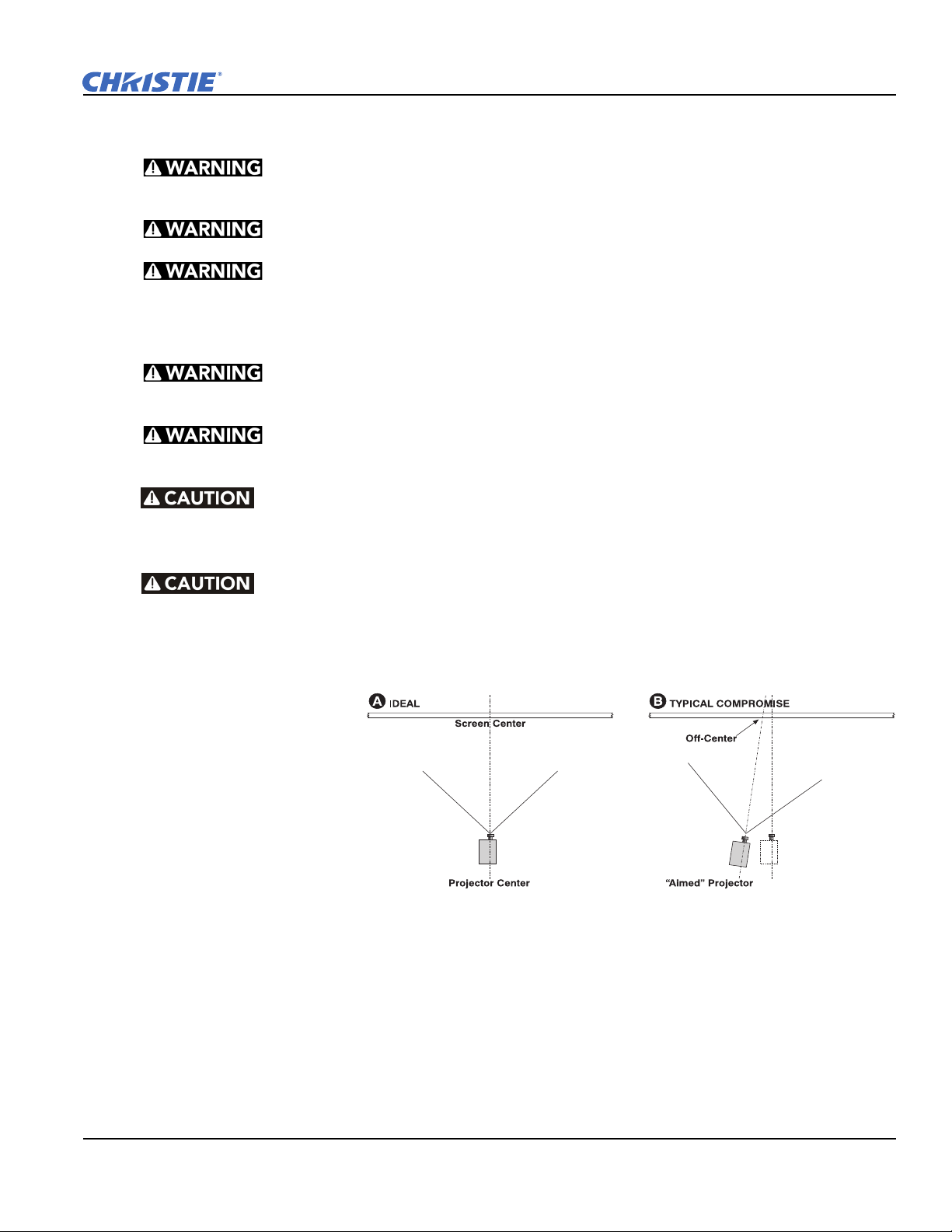
2.5 Position the Projector
1. Position the projector at an
appropriate throw distance
(projector-to-screen
distance) and vertical
position. Ideally, center the
projector with the screen.
If space is limited, aim the
projector slightly offcenter as shown in Figure
2-2. This increases side
keystoning, but reduces
the horizontal lens offset
required.
2. Attach the supplied safety strap to the back of the projector and fasten it to its mounting surface. Use of the
strap is mandatory to prevent the projector from tipping when a lens or auxiliary lens mount is installed.
NOTE: keep the projector lens surface as parallel to the screen as possible, even if significantly above the
screen center. When a particularly short throw distance combines with a very wide screen, you may have to
forfeit some aim and stay more parallel to the screen. In such cases, some lens offset can reduce the keystone
distortion.
Figure 2-2 Position the Projector
D4K25 User Manual 2-5
020-100882-02 Rev. 1 (07-2012)
Page 22

Section 2: Installation and Setup
2.6 Adjust Tilt and Level the Projector
The projector’s rear safety strap must be in place before you adjust the
projector’s feet.
DO NOT over-extend the feet. Make sure several threads are engaged into
the projector’s baseplate.
The D4K25 lens should be centered and parallel with the screen. This orientation ensures optimum lens
performance with minimal offset. If this position is not possible (such as when the projector is significantly
higher than the center of the screen), it is better to rely on offset rather than extra tilt.
Use a protractor to measure the degree of screen tilt and then extend or retract the projector feet to match this
angle.
NOTE: The front-to-back tilt of the projector must not exceed 15°. This limit ensures safe lamp operation and
the proper positioning of the liquid cooling reservoir
To adjust the vertical or horizontal position of the projector, extend or
retract the adjustable feet on the bottom of the projector by rotating them.
Once the required adjustment is made, tighten the lock nut.
If you need to adjust the vertical or horizontal position of the projector
beyond what the standard feet allow, you can install two 6 inch extension
rods to increase the amount of adjustment. To install the extension rods
safely:
1. Prop the rear of the projector up to access and remove the two rear
feet. This can be done by one person holding the back end of the
projector up slightly so another person can unthread the feet OR by
propping up the back of the projector with a sturdy object.
2. Add the extension rods to the standard feet.
Figure 2-3 Adjust Feet
3. Thread the newly extended feet back into the projector’s baseplate.
Adjust the feet until the desired tilt is achieved.
4. Lock the feet in place by turning each lock nut until it fits tight against the projector.
2-6 D4K25 User Manual
020-100882-02 Rev. 1 (07-2012)
Page 23
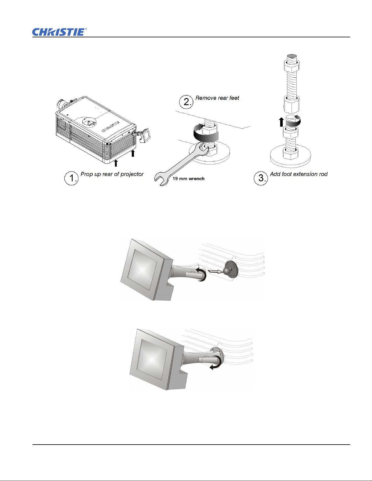
Figure 2-4 Using the Foot Extension Rods
Section 2: Installation and Setup
2.7 Install the Touch Panel Controller (TPC)
1. Loosen the mounting arm so that the end fits over the ball joint located on the rear panel of the projector.
Figure 2-5
2. Tighten the mounting arm until it fits tightly on the joint.
Figure 2-6
3. Connect the cable from the TPC to the connector on the rear panel of the projector.
4. Adjust the angle of the TPC.
D4K25 User Manual 2-7
020-100882-02 Rev. 1 (07-2012)
Page 24
Section 2: Installation and Setup
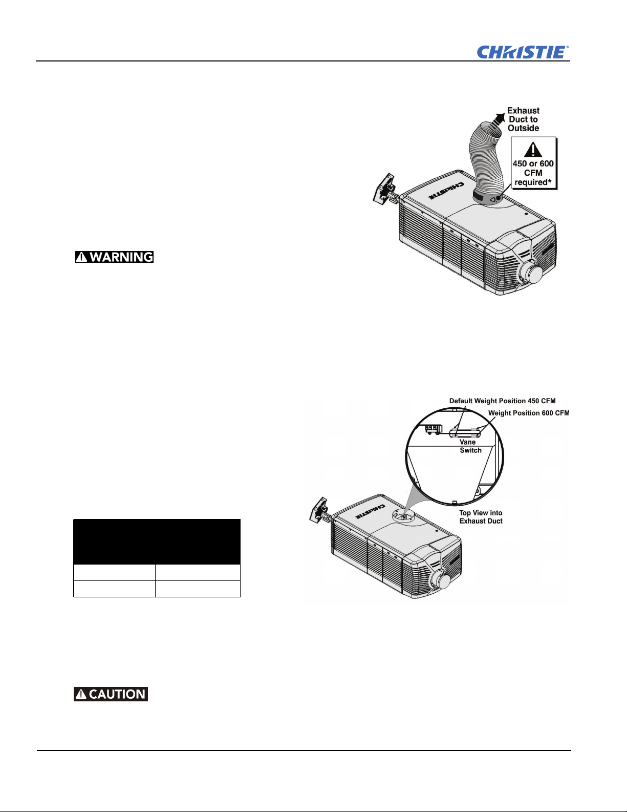
2.8 Connect External Exhaust Ducting
Connect the existing outside-venting ductwork to the 8 inch
diameter exhaust port on the top of the projector. Confirm that
there are no obstructions or bends in the ducting, all air intakes
are free of obstructions, and the vane switch at the exit duct
moves freely.
The pre-installed outside-venting duct should be rigid at the
projector and must also include a heat extractor and blower that
maintains a minimum of 450 CFM* when the projector is
operating at less than or equal to 25°C ambient and less than
3,000 feet, when measured at the projector exhaust opening.
• *600 CFM is required in projection rooms with an
ambient temperature above 25°C or located at an
elevation greater than 3000 feet above sea level.
• At minimum, a 10” long, strong metal duct must be
installed at the projector to prevent glass shards
from exiting the duct in the event of a lamp explosion.
Figure 2-7 Connect Exhaust Ducting
2.8.1 Determine the Projector Exhaust CFM Value
Use an airflow meter to measure the ft/min or ft/
sec at the rigid end of the open exhaust duct that
connects to the projector. Take the measurement
at the very end of the duct without the projector
connected. Use this formula to determine the
CFM value for the projector:
Measured linear ft/min x 0.35 = CFM
Table 2.1 Airflow Requirement
Min.
Lamp Type
2.0 kW 450 CFM*
3.0 kW 450 CFM*
Add an extractor or a booster if there is
insufficient airflow. Do not mount the extractor
on the projector as this may introduce some vibration into the image. NOTE: To prevent the projector from
overheating or becoming unsafe, an alarm sounds if the duct is obstructed or a fan fails. It is recommended
that you regularly verify that the exhaust is functioning correctly.
Airflow (CFM)
Required
Figure 2-8 Exhaust Duct Vane Switch
Never disable the vane switch. Attempting to operate the projector with inad-
equate airflow can result in dangerous overheating of the projector.
2-8 D4K25 User Manual
020-100882-02 Rev. 1 (07-2012)
Page 25

2.9 Remove the Shroud
To access the MLM and lens, you need to remove
one shroud. Remove the second shroud when you
use a Motorized Auxiliary Lens Mount or a Real
D Z or plug AC power cord into front face of the
projector.
1. Using finger pressure, push down on the
locations specified by the red arrows in the
diagram.
2. Carefully slide the shroud sideways and
forward away from the MLM and lens.
3. Place the shroud cover on a clean surface to
prevent scratches.
2.10 Install the Primary Lens
The lens seals the projection head, preventing contaminants from entering the main electronics area. Do not
operate the projector without a lens installed. Install a lens plug when you install or transport the projector.
Section 2: Installation and Setup
Figure 2-9 Shroud Removal
NOTE: 1) Make sure the zoom ring is against the front of motor mount for lenses: 1.6-2.4:1, 1.8-3.0:1, 2.15-
3.6:1. 2) Make sure the zoom ring is against the back of motor mount for lenses: 1.45-2.05:1, 1.25-1.83:1. 3)
All other lenses: Leave a gap between the rotating zoom section of lens and motor mount.
1. Unpack the zoom motor kit.
2. Use a flathead screwdriver to install the zoom motor mount onto the lens with a screw clamp.
D4K25 User Manual 2-9
020-100882-02 Rev. 1 (07-2012)
Page 26
Section 2: Installation and Setup
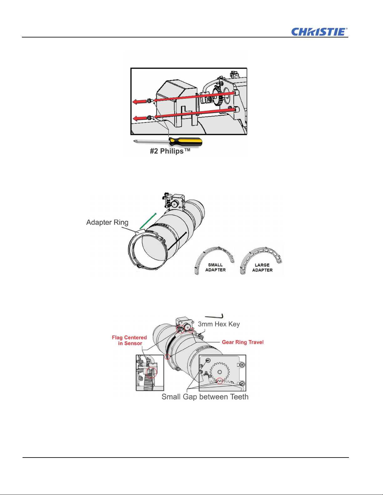
3. Remove the cover from the zoom motor mount with a Phillips screwdriver. Keep the hardware and cover.
4. Install zoom gear ring and adapter onto the lens.
NOTE: 1) Use a small adapter for lens 1.8-3.0. 2) Use a large adapter for lens 1.45-2.05, 2.15-3.6, 1.25-
1.83:1 3) All other lenses do not need an adapter.
5. Verify that there is full travel of the gear ring, and the alignment of the sensor is correct.
NOTE: There must be a small gap between the gears to prevent binding. To ensure there is a gap, loosen
the screws and readjust the gap. Tighten the screws when you have completed the adjustment.
Figure 2-10
2-10 D4K25 User Manual
020-100882-02 Rev. 1 (07-2012)
Page 27

Section 2: Installation and Setup
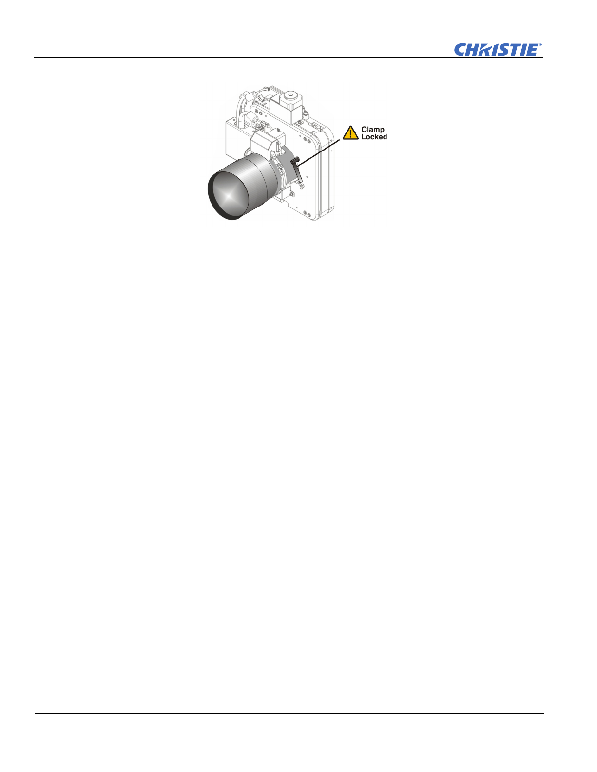
6. Turn the lens clamp to the OPEN position on the MLM and fully insert the assembly straight into the lens
mount opening without turning. When the lens is fully inserted it is seated properly within the lens mount
and the aperture is installed correctly.
7. Install the cover with the screws.
NOTE: Make sure the cover is between the mounting tabs.
8. Connect the harness wires.
D4K25 User Manual 2-11
020-100882-02 Rev. 1 (07-2012)
Page 28
Section 2: Installation and Setup
9. Position the lens clamp DOWN to lock the lens assembly in place.
10. Calibrate the lens. See Section 4.3 Basic Image Alignment for details.
11. Install the shroud.
2.11 Install the Optional Anamorphic Lens
1. Make sure to optimize your primary lens first for best optical alignment, offset and boresight.
2. Install the auxiliary lens mount using the instructions included with the kit.
3. Loosen the holding clamp on the auxiliary lens mount. Adjust the rotation of the anamorphic lens so the
image remains perfectly square with anamorphic in and out.
4. Adjust the location of the anamorphic lens so that the image does not shift left or right with the anamorphic
lens in and out.
5. Adjust the location of the anamorphic lens so the image passes through the center as much as possible
without vignetting, reducing side or corner brightness, especially in wide angle projection.
6. Remove the anamorphic lens and turn the Focus knob to re-focus the primary lens. The goal is for good
focus at the center and on all sides.
7. Re-install the anamorphic lens and check the focus.
8. If center-to-edge horizontal focus in the image needs improvement, rotate the focus barrel.
2.12 Install the Optional Wide Converter Lens
1. Optimize the primary projector lens for optical alignment, offset, and boresight.
2. Install the Auxiliary Lens Mount and Wide Converter Lens (WCL) using the instructions included with the
kit.
3. Adjust the vertical and horizontal position of the WCL to align it with the primary lens.
4. Adjust the pitch, up or down to equalize the top and bottom clearance to the primary lens barrel.
5. Adjust yaw to make the clearance between both lens barrels equal from side-to-side.
2-12 D4K25 User Manual
020-100882-02 Rev. 1 (07-2012)
Page 29
2.13 Install the Lamp
This procedure should only be performed by a Christie accredited technician.
High-pressure lamp may explode if improperly handled. Always wear approved protective
safety clothing whenever lamp door is open or when handling the lamp.
1. If the projector is operating, turn it off and allow it to cool a minimum of 10 minutes.
2. Turn the breaker switch for the projector off.
3. Disconnect the projector from AC power.
4. Put on your protective clothing and face shield.
5. Use the security key to open the lamp door and access the lamp cooling compartment. Do not place heavy
objects on the open lamp door.
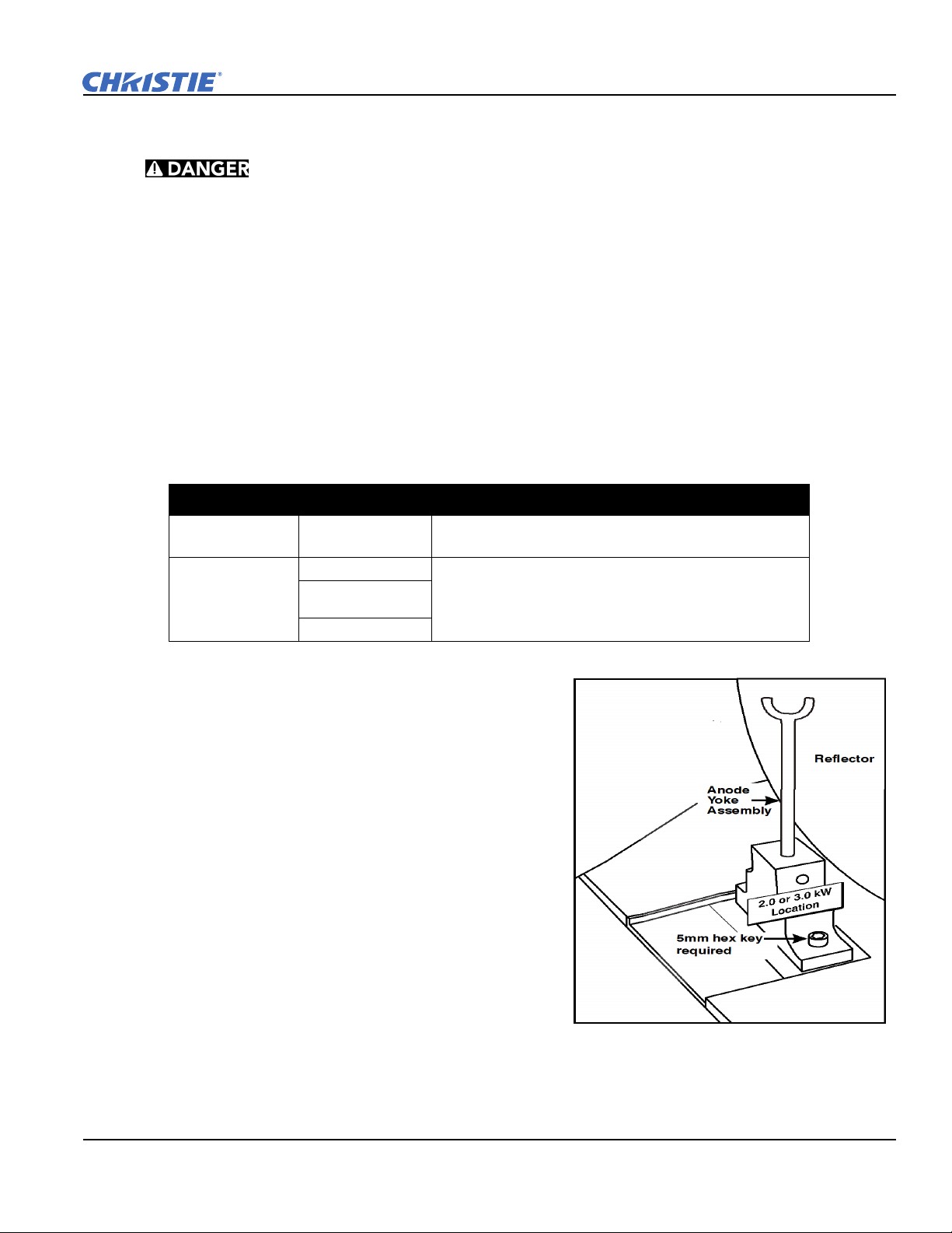
6. Install the anode yoke assembly. Use this table to determine the correct position of the anode yoke
assembly.
Table 2.2 Lamp Types Available for D4K25 and Anode Yoke Position
LAMP TYPE ANODE YOKE POSITION
Section 2: Installation and Setup
2.0 kW
3.0 kW
CDXL-20
CDXL-30
CDXL-30SD (short
arc)
CXL-30
Move the lamp cradle as far forward as possible (position
closest to igniter)
Move the lamp cradle to the rear position, which is approximately
1” closer to the reflector.)
7. Install the lamp. See Section 7.9 Replace the Lamp for
lamp replacement instructions. Observe all warnings,
and wear protective safety gear.
Figure 2-11 Yoke assembly installa-
D4K25 User Manual 2-13
020-100882-02 Rev. 1 (07-2012)
Page 30
Section 2: Installation and Setup
2.14 Connect the Projector to AC Power with a Permanent Connection
1) Certified electrician required. 2) Ground (earth) connection is necessary for
safety. Never compromise safety by returning the current through the ground. 3) Connect
ground
the cable from rubbing against the projector knockout plate and becoming damaged.
When connecting the projector to AC power, follow all electrical codes for your location. In addition, follow
these recommendations:
• A 30A maximum double pole, UL listed wall circuit breaker is required. It must be part of the building
installation and easily accessible.
• Use 10AWG or 8AWG wiring. The distance between the wall circuit breaker and the projector must not
exceed 20 meters using 10AWG cables or 30 meters using 8AWG cables.
• For North American installations, use at least 10AWG copper wires for the connection of the main AC supply to the projector’s ground lug.
• Copper or aluminum are acceptable as conductor wiring material to the terminal block.
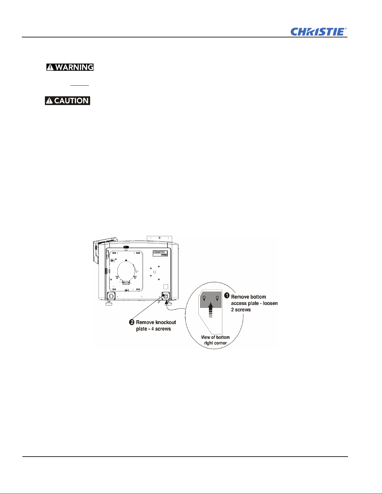
1. On the bottom of the projector in the front right corner, loosen the two screws and slide the plate forward to
FIRST to reduce shock hazard from high leakage.
Use an appropriate strain relief connector on the AC supply cable to prevent
expose the terminal block.
Figure 2-12
2. Remove the knockout plate located in the bottom right corner of the front bezel. The AC supply is routed
to the terminal block through an appropriate strain relief mounted on this knockout plate.
3. Connect the AC power source to the terminal block, beginning with the ground lead first. Use an
appropriately sized strain relief connector with the knockout plate provided to ensure adequate
environmental sealing and to prevent the cables from wear and accidentally being torn out. NOTES: 1)
The terminal block accommodates up to an 8 AWG wire. 2) If desired, a 90° strain relief connector can be
used to route the power cable in a downward direction.
2-14 D4K25 User Manual
020-100882-02 Rev. 1 (07-2012)
Page 31

Section 2: Installation and Setup
Figure 2-13
4. Replace the knockout plate and the bottom access panel over the terminal block.
Figure 2-14
D4K25 User Manual 2-15
020-100882-02 Rev. 1 (07-2012)
Page 32

Section 2: Installation and Setup
2.15 Connect the Projector to AC Power with a Pluggable Type B Connection
When connecting the projector to AC power, follow all electrical codes for your location. In addition, follow
these recommendations:
• There must be easy access to the current protection device or breaker in the building.
• Use minimum 10AWG wiring, with a maximum length of 4.5 m for U.S and Canada. For international installations the length should be based on the local electrical codes.
• The socket-outlet is installed near the equipment and is easily accessible.
• The plug can be used as the device disconnect and is near the unit and easily accessible.
Figure 2-15 Nema-L630A 250V Male Power Plug (116-102104-01)
Actual Length 1.5 Meters
1. On the bottom of the projector in the front right corner, loosen the two screws and slide the plate forward to
expose the terminal block.
2. Remove the knockout plate (four screws) located in the bottom right corner of the front bezel.
3. Connect the AC power source to the terminal block, beginning with the ground lead first. Tighten screws
securely.
4. Secure the knockout plate (four screws) and the bottom access panel (two screws) over the terminal block.
2-16 D4K25 User Manual
020-100882-02 Rev. 1 (07-2012)
Page 33

Section 2: Installation and Setup
2.16 Configure the Optional Uninterrupted Power Supply
A UPS allows the projector head electronics to remain operable during a power failure.
Unplug the LVPS input connection from Main Power and connect it to the UPS input plug. Re-use the dummy
plug from the UPS connection with the unused Main Power plug.
Figure 2-16
2.17 Connect Sources and Turn the Projector On
1. Assign the projector a unique IP address and enter a baud rate:
• Tap Menu > Administrator Setup > Communications Configuration.
• Enter the IP address for the projector in the IP Address field.
• Select a baud rate for the input device in the Serial Speed (Baud) list.
2. Enter lamp information:
• Tap Menu > Advanced Setup > Lamp History.
• Tap Add Lamp.
• Complete the fields in the Add Lamp dialog.
• Tap Save.
3. Tap and hold the green power button to turn the projector on.
4. Complete a LampLOC™ alignment on the new lamp:
• Tap Menu > Advanced Setup > LampLOC™
• Tap Do Auto.
5. Complete an optical alignment to optimize images displayed on screen. See Section 4.3 Basic Image
Alignment.
Setup.
6. Adjust optical components if required.
D4K25 User Manual 2-17
020-100882-02 Rev. 1 (07-2012)
Page 34

Page 35

3 Connect Devices to the Projector
This section provides information and procedures for connecting input devices to the projector. You connect
input devices to the Projector Intelligence Board (PIB3G) located on side of the projector.
These communication ports are accessible by removing the side source and communication access panel.
When connecting devices, route all cables along the channels located on the bottom of the projector and up
through the opening in the frame to the communication connection port.
Replace the access panel to ensure server and source connections remain secure.
Figure 3-1 Connecting Server Sources
D4K25 User Manual 3-1
020-100882-02 Rev. 1 (07-2012)
Page 36

Section 3: Connect Devices to the Projector
Figure 3-2 Connecting PC Sources
3-2 D4K25 User Manual
020-100882-02 Rev. 1 (07-2012)
Page 37

3.1 Connect a Computer or Server
To communicate with the projector from a computer, server or an existing network, connect the equipment to
the Ethernet hub or switch.
For applications or equipment utilizing serial communications, use the Christie-proprietary serial protocol to
connect to the RS232 PIB3G port on the PIB3G. When using Christie serial protocol over Ethernet connect to
port 5000.
protocol and is intended for Christie accessories or automation controllers only.
NOTICE: The RS232 PIB3G port located on the PIB3G faceplate utilizes Christie-proprietary
Section 3: Connect Devices to the Projector
Figure 3-3 Connecting Communications
D4K25 User Manual 3-3
020-100882-02 Rev. 1 (07-2012)
Page 38

Section 3: Connect Devices to the Projector
3.2 Connect Devices to the SCCI Port
The Simple Contact Closure Port (SCCI) port is a DB-9 (male) connector is located on the PIB3G input panel
and is used to control a limited set of projector functionality through contact closures. This table lists the
control functions available through the SCCI:
Table 3.1 SCCI Connector Pinouts
PIN SIGNAL NAME DIRECTION DESCRIPTION
1 +5V Standby Out Current limited 5VDC supply
2 Lamp ON In Projector at Power ON mode, lamp is
3 +5V Standby Out Current limited 5VDC supply
4 Lamp OFF In Projector at full power, lamp is OFF
5 +5V Standby Out Current limited 5VDC supply
6 Douser Closed In Close douser
7 Douser Open In Douser open
8 Health Output Out Open Collector Low when one of the
9 Ground Out Ground
ON
following interlocks is tripped or conditions present:
• Lamp Door
• Lamp Blower
• Extractor
• Tamper
• Ballast Communication
NOTE: All SCCI inputs require a pulse input of 50ms to several seconds to operate reliably. Inputs are 5V
resistor current limited LED’s inside of optocouplers.
A “Health Output” on this connector is also provided for locations that require a projector Health Output. The
output is an open-collector circuit which only draws power when the projector is deemed to be “un-healthy”.
The primary use of the Projector Health Output is to ensure that patrons are not left in a dark location due to
projector fault. Therefore, any fault that results in the content playback stopping should cause this circuit to
draw power and indicate an un-healthy state. The projector is always considered to be “healthy” in Standby
Mode since there is no fear of projector fault causing an impact to patrons in this mode.
3-4 D4K25 User Manual
020-100882-02 Rev. 1 (07-2012)
Page 39

3.3 Connect Devices to the GPIO Port
The GPIO port is a 37-pin D-sub connector (female) located on the PIB3G input panel and provides 8 input
and 7 output signals for connecting external devices to the projector. To configure the pins on the connector,
tap Menu > Administrator Setup > GPIO Setup.
Figure 3-4 Admin: GPIO Setup Window and GPIO Port Location on Projector
Section 3: Connect Devices to the Projector
As shown below, each available pairing of pins (+/–) is defined as either an input or output. Four inputs and
three outputs have already been predefined. Configure a pin as an input if you want the projector to respond to
an incoming signal, or as an output if you want an external device to respond to the projector.
Inputs Positive Negative Description
GPIN #1 Pin 1 Pin 20 3-D L/R Input Reference
GPIN #2 Pin 2 Pin 21 3-D L/R Display Reference
GPIN #3 Pin 3 Pin 22 Reserved
GPIN #4 Pin 4 Pin 23 Reserved
GPIN #5 Pin 5 Pin 24 Input
GPIN #6 Pin 6 Pin 25 Input
GPIN #7 Pin 7 Pin 26 Input
GPIN #8 Pin 8 Pin 27 Input
Outputs Positive Negative Description
GPOUT #1 Pin 9 Pin 28 External 3-D L/R Output Reference
GPOUT #2 Pin 10 Pin 29 Reserved
GPOUT #3 Pin 11 Pin 30 Reserved
GPOUT #4 Pin 12 Pin 31 Output
GPOUT #5 Pin 13 Pin 32 Output
GPOUT #6 Pin 14 Pin 33 Output
GPOUT #7 Pin 15 Pin 34 Output
PROJ_GOOD Pin 16 Pin 35 Projector Good
D4K25 User Manual 3-5
020-100882-02 Rev. 1 (07-2012)
Page 40

Section 3: Connect Devices to the Projector
If you are wiring your own GPIO cable for use with a server or 3D device such as an IR emitter or a polarizer,
follow the circuit diagram.
Figure 3-5 GPIO Circuit Diagram
3-6 D4K25 User Manual
020-100882-02 Rev. 1 (07-2012)
Page 41

3.4 Connect Devices to the 3D Connector
The 3D connector is a 15-pin D-sub connector (female) located on the PIB3G Board. The following table lists
the control functions available through the 3D connector.
PIN SIGNAL NAME DIRECTION DESCRIPTION
1 +12V Out Power to 3D device. Maximum 1A (total between both
2 GND / Ground
3 GND / Ground
4 RS232_RX In Data to projector from 3D device. 1200 Baud, 8 bits, no
5 RS232_TX Out Data to projector from 3D device. 1200 Baud, 8 bits, no
Section 3: Connect Devices to the Projector
+12V pins).
parity. Currently unsupported.
parity. Currently unsupported.
6 CONN_3D_MODE+ Out SYNC from projector. To projector GPO collector.
7 CONN_SYNC+ Out SYNC from projector. To projector GPO collector.
8 3D_INPUT_REFRERENCE+ In 3D L/R Input Reference (P)
9 +12V Out Power to 3D system. Maximum 1A (Total between both
10 3D_INPUT_REFRERENCE- In 3D L/R Input Reference (N)
11 3D_DISPLAY_REFERENCE+ In 3D L/R Input Reference (P)
12 3D_DISPLAY_REFERENCE- In 3D L/R Input Reference (P)
13 CONN_3D_MODE- Out 3D mode state from projector. From projector GPO
14 CONN_SYNC- Out SYNC from projector. From projector GPO emitter.
15 Not connected
Compatible with current projector GPIO requirements
and restrictions. (24VDC max, 50mA max)
3D ON = Hi logic level = O/P transistor ON
3D OFF = Low logic level = O/P transistor OFF
Compatible with current projector GPIO requirements
and restrictions. (24VDC max, 50mA max)
(Voltage Limit: 1.4VDC to 12VDC)
+12V pins)
(Voltage limit: 1.4VDC to 12VDC)
(Voltage limit: 1.4VDC to 12VDC)
(Voltage limit: 1.4VDC to 12VDC)
emitter. Compatible with current projector GPIO
requirements and restrictions. (24VDC max, 50mA
max)
Compatible with current projector GPIO requirements
and restrictions. (24DC max, 50mA max)
D4K25 User Manual 3-7
020-100882-02 Rev. 1 (07-2012)
Page 42

Page 43

4 Adjust the Image
This section provides information and procedures for adjusting the projector image.
4.1 Maximize Light Output
To ensure optimal operation and peak screen brightness, use LampLOC™ to adjust the lamp position
whenever you install a new lamp. When you complete the LampLOC adjustment, the lamp is centered and is
the correct distance from the illumination system. Before running LampLOC, verify that:
• The anode yoke is in the correct position for the lamp type.
• The lamp extension nut is installed when using a CDXL-30SD lamp. Remove the nut if you are not using a
CDXL-30SD lamp.
• The lamp is on and the douser is open.
1. On the Touch Pad Controller, tap the Test Patterns icon.
2. Tap the Full Screen White test pattern.
3. Tap Menu > Advanced Setup > LampLOC™
4. Tap Do Auto.
4.2 Calibrate Screen Brightness (fL)
1. On the Touch Pad Controller, tap Menu > Administrator Setup > Foot Lamberts Calibration.
2. Complete the Foot Lamberts Calibration wizard.
4.3 Basic Image Alignment
This procedure ensures that the image reflected from the digital micromirror device (DMD) is parallel and
centered with the lens and screen. This procedure must be completed before you complete a boresight
adjustment.
1. Verify the projector is properly positioned relative to the screen. See Section 2.5: Position the Projector.
2. Display a test pattern that you can use to analyze image focus and geometry. The framing test pattern
works well for this.
3. Perform a preliminary focus and (if available) a zoom adjustment with the primary lens. Focus the center
of the image first. See Section 5.6: Work with Lenses.
4. Hold a piece of paper at the lens surface and adjust the offsets until the image is centered within the lens
perimeter.
Setup.
5. With the framing test pattern on screen, re-check projector leveling so the top edge of the image is parallel
to the top edge of the screen.
D4K25 User Manual 4-1
020-100882-02 Rev.1 (7-2012)
Page 44

Section 1: Introduction
4.4 Adjust Offset
Project an image with the primary lens. Always adjust offset before boresight.
Select a framing test pattern and then adjust the horizontal and vertical offset to display a square image on the
screen with minimal projector aiming error.
NOTES: 1) For the best optical performance and minimize keystone error, use offset and not aiming to center
the image in off axis installations. 2) Avoid extreme tilts or offsets. Corner vignettes on a white test pattern
indicate extreme offset that should be avoided using mechanical alignment.
4.5 Adjust Offset with an ILS
Project an image with the primary lens. Always adjust offset before boresight. Ensure the correct lens is
selected in the Advanced Setup: Lens Adjust window before calibration to ensure you remain within the
applicable boundary of the installed lens.
1. Tap Menu > Advanced Setup > Lens Setup.
2. Tap Enable Automatic ILS. Enabling Automatic ILS overwrites the pre-defined settings for the channel.
3. Tap the Test Patterns icon and select a framing test pattern.
4. Tap Menu > Advanced Setup > ILS File Setup.
5. Tap the directional arrows in the Offset area. For best optical performance, make sure to minimize
keystone error by using offset more than aiming to center the image in off axis installations. Avoid extreme
tilts or offsets. Corner vignettes on a white test pattern indicates extreme offset that should be avoided
using mechanical alignment.
4.6 Adjust Left and Right Boresight
When performing these adjustments the goal is to balance the tilt of the lens mount to compensate for screen to
projector tilt, but also to precisely maintain the original factory settings of the lens mount axial position.
1. Loosen the horizontal locking screw.
Horizontal
Locking
Horizontal
Boresight
Bolt
Screw
Figure 4-1 Horizontal Boresight
2. Extend the lens focus completely.
4-2 D4K25 User Manual
020-100882-02 Rev.1 (7-2012)
Page 45

Section 1: Introduction
3. Adjust the Focus using the focus knob to retract the lens. Watch the image at the left edge of the screen
until it comes into focus. If the entire screen is in focus, proceed to step 7.
Figure 4-2 Adjust Focus
4. Continue retracting the lens.
a. If the right side of the image comes into
focus before the lens is completely retracted,
adjust the horizontal boresight bolt to balance the left and right edges.
b. If the right side of the image fails to come
into focus, adjust the horizontal boresight
bolt.
5. When both sides appear equally blurry, adjust
the horizontal or vertical offset to re-center the
image.
6. Repeat steps 1 - 5 until both sides of the image
are focused.
7. Tighten the horizontal hold screw to maintain
your adjustments.
8. Check the boresight again.
Figure 4-3 Aerial View Illustrating
Misaligned Boresight
D4K25 User Manual 4-3
020-100882-02 Rev.1 (7-2012)
Page 46

Section 1: Introduction
4.7 Adjust Top and Bottom Boresight
1. Focus the image at the top edge of the screen.
2. Loosen the vertical hold screw.
3. Extend the lens focus completely.
4. Adjust the Focus knob to retract the lens. Watch the image at the
top edge of the screen until it comes into focus. If the entire screen
is in focus, proceed to step 8.
5. Continue retracting the lens.
a. If the bottom edge of the image comes into focus before the
lens is completely retracted, adjust the vertical boresight bolt
to direct or aim the lens mount UP towards the top of the
screen to balance out the top/bottom edges.
b. If the top edge of the image is not in focus, adjust the vertical
boresight bolt to direct or aim the lens mount toward the bottom of the screen.
6. When both sides appear equally blurry, adjust the horizontal and/or vertical offset to re-center the image on
the screen.
Vertical
Boresight
Bolt
Vertical
Locking
Screw
Figure 4-4 Vertical Boresight
7. Repeat Steps 2 - 5 until the top and bottom of the screen are both well-focused.
8. Re-focus the center of the image. The goal is for good focus at the center and on all sides.
9. Tighten the vertical hold screw to maintain your adjustments.
Figure 4-5 Adjust Vertical Boresight
10. Check the boresight again.
4-4 D4K25 User Manual
020-100882-02 Rev.1 (7-2012)
Page 47

4.8 Adjust Top and Bottom Boresight with an ILS
1. Loosen the Vertical Locking Screw.
2. Extend the lens focus completely.
3. Adjust the Focus to retract the lens using the counter-clockwise
button on the ILS Adjust window. Watch the image at the top edge
of the screen until it comes into focus. If the image appears wellfocused on the top edge but not on the bottom, we need to
determine if the bottom edge focuses in front of or behind the
screen. If the entire screen comes into focus, skip to step 8.
4. Continue retracting the lens.
a. If the bottom edge of the image comes into focus before the
lens is completely retracted, then the image focuses in front of
the screen. To correct this problem, adjust the Vertical Bore-
sight Bolt to direct or aim the lens mount UP towards the top
of the screen to balance out the top/bottom edges.
b. If the top edge of the image fails to come into focus
then the image focuses behind the screen. To correct
this problem, adjust the Vertical Boresight Bolt to
direct or aim the lens mount DOWN towards the bottom of the screen.
Section 1: Introduction
Vertical
Boresight
Bolt
Figure 4-6 Vertical Boresight
Vertical
Locking
Screw
5. When both sides appear equally blurry, tap Menu >
Advanced Setup > ILS File Setup and tap the
directional arrows in the Offset area to center the image
on the screen.
6. Repeat Steps 2 - 5 until the top and bottom of the screen
are both well-focused.
7. Although all sides of the image should now be in focus,
the center of the image may be slightly blurry at this point. Re-focus the center of the image. The goal is
for good focus at the center and on all sides.
8. Adjust the Vertical Locking Screw to lock the lens mount in place and check boresight again.
4.9 Adjust DMD Convergence
UV EXPOSURE! Protective UV glasses must be worn when performing
convergence adjustments.
A convergence problem occurs when one or more projected colors (red, green, blue) appears misaligned when
examined with a convergence test pattern. Normally, the three colors should overlap precisely to form pure
white lines throughout the image and one or more poorly converged individual colors may appear adjacent to
some or all of the lines. Contact your Christie accredited service technician to correct DMD convergence
issues.
Figure 4-7 Adjust Vertical Boresight
D4K25 User Manual 4-5
020-100882-02 Rev.1 (7-2012)
Page 48

Section 1: Introduction
4.10 Fold Mirror Adjustment
If a corner or edge of an image is missing, the fold mirror might be misaligned with the optical system. To
correct this issue:
• Adjust the screw closest to the operator’s side (right side, when facing screen) to raise or lower the image.
• Adjust the screw on the left side to move the image left or right.
Figure 4-8 Fold Mirror Adjustment
4.11 Calibrating the System
Use the TPC interface for calibrating the image color performance and defining electronic screen masking.
This is required in your particular installation for the creation of Source, Screen, MCGD and TCGD files
necessary for proper display of incoming material. You can also define the system/network configuration for
communication links to the projector and transmit information to and from the D4K25 via an Ethernet or RS232 connection.
4-6 D4K25 User Manual
020-100882-02 Rev.1 (7-2012)
Page 49

4.12 Color Calibration
To ensure an accurate color display:
1. Measure the colors displayed on the screen from the center of the audience viewing location to determine
the Measured Color Gamut Data (MCGD) value.
2. On the Touch Pad Controller tap Menu > Advanced Setup > MCGD File Setup and enter the color
values in the x and y fields for the different colors.
3. Tap Save. The software automatically determines the Target Color Gamut Data (TCGD) value. The TCGD
value determines what corrections are needed to display the correct colors.
4.13 Electronic Screen Masking
You can use the masking tool to correct image edge blanking. The masking tool produces results that are
similar to filing the aperture plate in a film projector. After you create the Flat and Scope screen files you can
use them in multiple channels.Hardware Setup
Use an infrared emitter to control gating in active glasses, a polarizing Z-screen (Pi-cell) with passive glasses
or filter wheel with passive glasses.
Section 1: Introduction
D4K25 User Manual 4-7
020-100882-02 Rev.1 (7-2012)
Page 50

Page 51

5 Projector Operation
This section provides information and procedures for operating the projector.
5.1 Turn the Projector On
WARNING! Do not attempt to turn the projector on if the AC supply is not within the
specified voltage range.
1. Turn the circuit breaker for the projector on.
2. On the Touch Panel Controller (TPC), tap and hold the green power icon.
3. On the TPC, tap and hold the light bulb icon to ignite the lamp.
5.2 Turn the Projector Off
1. On the Touch Panel Controller (TPC), tap and hold the light bulb icon to turn the lamp off.
2. On the TPC, tap and hold the red power icon. The projector enters a cool down mode and the fans
and electronics stay on for 10 minutes. After this cool down period, the projector enters standby mode.
3. If you are servicing the projector, or removing the protective cover, disconnect AC and turn the breaker
OFF.
5.3 Projector Power States
This table identifies what occurs when you press the Power and Lamp icons on the Touch Panel Controller
(TPC).
Standby Power Mode
(Solid Yellow)
Power ON
Power OFF
Lamp ON
Lamp OFF
TPC Buttons Clicked:
To full power ON
(boot delay)
No action Power OFF
To power ON and lamp
ON (boot delay)
No action No action Lamp OFF (immediately) No action
Projector’s Current State:
Power ON/ Lamp OFF
(Green Blip)
No action No action Cancels cool down,
immediately
To lamp ON
(immediately)
Power ON / Lamp ON
(Solid Green)
Lamp OFF (immediately),
enters cool down mode
No action Cancels cool down,
Cooling Down
Mode (Yellow Blip/
Green Blip)
goes into full power
No action
goes to Lamp ON
(immediately)
D4K25 User Manual 5-1
020-100882-02 Rev. 1 (07-2012)
Page 52

Section 5: Projector Operation
5.4 Projector LED Status Indicators
Red, yellow, and green LEDs on the top and rear corners of the projector indicate the status of the projector.
The LEDs can be solidly lit, or they can flash frequently or intermittently. This table lists the LED state and its
associated meaning.
Table 5.1 Projector Status LED Legend
LED State Description
Solid Green
Green Blip
Solid Yellow
Yellow Blip/
Green Blip
Flashing Red
Solid Red
Lamp ON Power is ON, Lamp is ON.
Power ON Power is ON, Lamp is OFF. The lamp can be struck when in
Standby mode Power is OFF, Lamp is OFF. Power saving mode.
Cool down mode Transition to STANDBY mode.
New critical alarm or warning New critical alarm or warning has NOT been acknowledged
Existing critical alarm or warning Critical alarm or warning exists, but has been acknowledged
this mode.
Power is ON, Lamp is OFF.
The lamp can be struck when in this mode.
by operator.
by operator.
5.5 Work with the Lamp
This section provides information and procedures for optimizing lamp performance. Optimizing lamp
performance can ensure you receive the brightest, most uniform image possible for the life of the lamp.
5.5.1 Turning the Lamp On
1. Turn on the circuit breaker for the projector.
2. On the Touch Pad Controller (TPC) press and hold the green power icon for two seconds.
3. On the TPC, press and hold the lamp on icon for 2 seconds.
5.5.2 Turn the Lamp Off
1. On the Touch Pad Controller (TPC), press and hold the lamp off icon for two seconds.
2. On the TPC, press and hold the power off icon for two seconds.
3. Disconnect the projector from AC power and turn the projector circuit breaker off.
5.5.3 Adjust Lamp Power
1. Tap Menu > Advanced Setup > Lamp Power/LiteLOC Setup
2. Increase or decrease the Power% value.
3. Tap Set Target.
4. Select Enable LiteLOC™.
5-2 D4K25 User Manual
020-100882-02 Rev. 1 (07-2012)
Page 53

5.5.4 Change the Lamp Power Percentage
Entering a new Lamp Power percentage temporarily disables LiteLOC settings.
1. Tap Menu > Advanced Setup > Lamp Power/LiteLOC Setup.
2. Increase or decrease the Power% value.
5.5.5 Use LampLOC™ to Adjust the Lamp Position
Section 5: Projector Operation
To ensure optimal lamp performance and peak brightness at the screen for the life of the lamp, use LampLOC
to adjust the lamp position when you install a new lamp in the projector. After making the adjustment, the lamp
is well-centered and distanced correctly from the remainder of the illumination system. Before adjusting
LampLOC
™
, ensure the following criteria are met:
• The lamp must be ON and the douser (shutter) OPEN during adjustment. A 10-minute warm-up is recom-
mended. Ensure to follow all the criteria specified in Section 5.1 Turn the Projector On.
• Perform a white test pattern. This is recommended to allow you to view LampLOC
™
To automatically adjust LampLOC
:
1. Tap Menu > Advanced Setup > LampLOC™ Setup.
2. Tap Do Auto.
5.5.6 Manually Adjust the Lamp Position
1. On the Main screen of the TPC, tap the test patterns button.
2. Tap RGB-12bit-Full Screen White.
3. Mount a light meter on a tripod and center it with the lens. The distance from the lens does not matter. You
may need an attenuator or an internal foil aperture.
4. Tap Menu > Advanced Setup > LampLOC™ Setup.
5. Tap the directional arrows to adjust the value displayed in the Z field. The brightness reading in front of
the lens should be maximized.
™
progress on-screen.
™
6. Tap the directional arrows to adjust the values displayed in the X and Y fields. The brightness reading in
front of the lens should be maximized.
7. Repeat Steps 5-6, but take your readings at the screen instead of at the lens.
8. Run LiteLOC™ or LampLOC™ if required.
5.5.7 View Lamp Information
To view information on the lamps previously installed in the projector, or to add a new lamp:
Tap Menu > Advanced Setup > Lamp History.
5.5.8 Receive an Alarm when a Lamp Reaches Its Expiry Date
To receive an alarm when the lamp reaches its operational limit:
1. Tap Menu > Administrator Setup > Preferences.
2. Tap Lamp Expiry in the Alarm Triggers area.
D4K25 User Manual 5-3
020-100882-02 Rev. 1 (07-2012)
Page 54

Section 5: Projector Operation
5.5.9 Receive an Alarm when a Lamp Needs to be Rotated
To receive an alarm when the lamp reaches its operational limit:
1. Tap Menu > Administrator Setup > Preferences.
2. Tap Lamp Rotation in the Alarm Triggers area.
5.5.10 Lamp Expiry Hours
This table lists the maximum hours projector lamps can operate before replacement:
Table 5.2 Lamp Expiry Hours
Lamp Type Replace BEFORE
CDXL-20 (2.0 kW) 3500 hours
CDXL-30 (3.0 kW) 2500 hours
CDXL-30SD (3.0 kW) 2000 hours when operating at 2.5 kW
1100 hours when operating at 3.0 kW
5.5.11 Minimum and Maximum Lamp Power Ratings
This table lists the minimum and maximum power settings for projector lamps:
Table 5.3 Minimum and Maximum Lamp Power by Lamp Type
Lamp Type Lamp Size Min Lamp Power Max Lamp Power
CDXL-20 2 kW 1000W (50%) 2200W (110%)
CDXL-30 3 kW 1800W (60%) 3300W (103%)
5.6 Work with Lenses
The lens mount secures the primary zoom lens to the projector and provides setup adjustments for correct
boresight, and manually controlled focus, zoom and offsets.
Horizontal
Boresight
Bolt
HORIZONTAL
VERTICAL
OFFSET
Anchor Bolt
Figure 5-1 Lens Mount
Zoom Ring
Lock/Unlock
Lens
Focus
Vertical
Boresight
Bolt
5-4 D4K25 User Manual
020-100882-02 Rev. 1 (07-2012)
Page 55

Section 5: Projector Operation
The optional Intelligent Lens System (ILS) automates the process of adjusting the Focus, Horizontal (X) and
Vertical (Y) Offset, and Zoom in real-time using a motorized lens mount. ILS settings are saved in a file named
ILS Flat or ILS Scope.
Motorized Vertical Offset
Vertical Offset Knob
Horizontal Boresight Bolt
Horizontal Offset Knob
Motorized Horizontal Offset
Figure 5-2 Anatomy of the Lens Mount
An anamorphic lens (1.25x) can be installed into the optional auxiliary lens mount, then swung into place in
front of the primary lens to widen a “squeezed” image into a properly proportioned “scope” anamorphic
display.
5.6.1 Enable Automatic ILS Selected
When the Enable Automatic ILS check box is selected, the ILS adjusts each motor for the focus, offset, and
zoom to automatically move the lens based on the settings in the selected ILS file. Changing channels will
change the position of the lens, assuming the new channel uses a different ILS file. To make adjustments to an
ILS file, use the motorized lens mount adjustment features in the Advanced Setup: ILS File Setup window or
Lens Adjust window from the Main panel to adjust the focus, zoom and offset values. NOTE: Any changes
made to the focus, offset and zoom values will overwrite the current values in the ILS file, therefore these
changes will affect every channel that uses this ILS file.
Motorized Zoom
Anchor Bolt
Lock/Unlock Lens
Focus
Vertical Boresight
5.6.2 Enable Automatic ILS NOT Selected
When the Enable Automatic ILS check box is NOT selected, the lens does not move unless you make
adjustments to the focus, offset and zoom from the Lens Adjust window launched from the Main panel (the
ILS File Setup window is not available when the
settings will NOT overwrite the ILS values and changing channels will not affect the position of the lens.
The following table provides an example of what happens to the lens position and saved ILS Flat values when
you adjust the focus, zoom, and offset in both states of the Enable Automatic ILS feature.
D4K25 User Manual 5-5
020-100882-02 Rev. 1 (07-2012)
Enable Automatic ILS check box is not selected). These
Page 56

Section 5: Projector Operation
Table 5.4 Example - ILS Flat Values and Lens Position with Enable Automatic ILS
Focus
Zoom
Horizontal
Starting
Position
Original
ILS Flat
Values
-155 -200 -200 0 -200 -155 -200
100 125 125 25 125 100 125
035351535035
Adjust ILS Flat Values with
Enabled Automatic ILS
Selected
Adjusted
Lens
Position
ILS Flat
Values
(New
positions are
saved to the
ILS file
)
Change to
a Channel
with
ILS Scope
Values
(Changing
channels
changes the
lens position)
Adjust ILS Flat Values with
Enabled Automatic ILS NOT
Selected
Adjusted
Lens
Position
Lens
Position
ILS Flat
Values
(New
positions are
not saved to
the ILS file
Change to
a Channel
with
ILS Scope
Values
(Changing
channels does
)
not change the
lens position
Offset (x)
Vertical
256 375 375 200 375 256 375
Offset (y)
Using the offset, focus, and zoom knobs on the lens mount does not save the settings to the ILS file. These
settings will be lost once the
Enable Automatic ILS check box is selected in the Advanced Setup: Lens Adjust
window.
)
5.6.3 Access the ILS
On the Main screen of the TPC, tap Advanced Setup > ILS File Setup.
5.6.4 Enable ILS on a Channel
1. On the Main screen of the TPC, tap a channel.
2. Tap the Test Patterns button and then tap a test pattern.
3. On the Main screen of the TPC, tap Lens Adjust.
4. Tap Enable Automatic ILS to automatically apply the active channel settings.
5.6.5 Alter the Active ILS Settings
1. On the Main screen of the TPC, tap Lens Adjust.
2. Tap
Enable Automatic ILS.
3. Tap the directional arrows to adjust the values displayed in the X, Y, and Zoom fields. These values overwrite the ILS settings.
5.6.6 Maintain Lens Position Regardless of Selected Channel
1. On the Main screen of the TPC, tap Lens Adjust.
2. Clear the Enable Automatic ILS check box.
3. Tap OK.
5-6 D4K25 User Manual
020-100882-02 Rev. 1 (07-2012)
Page 57

Section 5: Projector Operation
4. Adjust the focus, Horizontal (X) and Vertical (Y) offset, and zoom by tapping the applicable button.
NOTE: This does not over-write the system settings for the ILS. If
Enabled Automatic ILS is selected again,
the ILS will position the lens to the saved channel settings.
5. If the
Quick Reset or Lens Calibration buttons are tapped in the Advanced Setup: Lens Setup window, the
lens returns to this remembered location. Also, this setting is remembered across system resets and
reboots.
5.6.7 Reset the ILS
The ILS must be reset when:
• the lens has been moved
• manual adjustments have been made to horizontal or vertical offset, zoom or focus
• a power outage occurred during a channel change
• ILS settings are drifting within a short period of time
1. On the Main screen of the TPC, tap Lens Adjust.
2. Tap Quick Reset. If Enable Automatic ILS is not selected, the lens returns to the stored settings.
5.6.8 Calibrate the ILS
You must calibrate the ILS must when you install a new lens.
1. On the Main screen of the TPC, tap Lens Adjust.
2. Tap Full Calibration. If Enable Automatic ILS is not selected, the lens returns to the stored settings.
5.7 Display Content
To display content from standard or high definition sources, connect the source to the DVI-D A and DVI-D B
ports on the input panel. The DVI port auto-detects progressive scan and digital RGB sources and displays
them in their original format. Using two DVI ports as a higher-bandwidth dual-link or twin-link pair is not
supported.
The 3G-SDI ports accept 3G, HD, and SD signals. 4 SDI connectors, 2 from the PIB3G and 2 from the 3GIC
option card, can be used to input 4K resolution image. Each SDI port can accept input from a 2K source. The
top-left corner of the image is sourced by the PIB3G main board channel A, the top-right corner from channel
B, the bottom-left corner from the option card channel A, and the bottom-right corner from the option card
channel B. The 4 inputs must be synchronized with maximum relative delay < 60 pixel clocks. The input
format can be either in YC 4:2:2 10bit or RGB 4:4:4 12bit For a list of compatible DVI and 3G-SDI sources,
see Section Appendix A: Specifications.
5.8 Selecting a Source
The projector uses pre-configured channels to determine how to display images from different sources. Each
channel file contains the optimum processing and display settings for the source. You select channels on the
Main Touch Pad Controller (TPC) screen. If the channel you need is not listed on the Main panel, click All.
D4K25 User Manual 5-7
020-100882-02 Rev. 1 (07-2012)
Page 58

Page 59

6 Projector Menus
This section provides information and procedures for using projector menus. You can use projector menus to
adjust projector settings and view status information.
6.1 Using the Touch Panel Controller (TPC)
The TPC is a touch-sensitive screen that you use to control the projector. You can use the TPC to turn the
projector and lamp on or off, select channels, and view status information. The TPC is mounted on the rear of
the projector. You can tilt and turn the TPC to improve the viewing angle. There are two USB ports under a
cover on the rear of the TPC that you can use to download log files and install software upgrades. You can
disconnect the TPC from the projector and an optional cable allows you to control the projector from a
maximum distance of 100 feet.
If the TPC fails or is disconnected, press the emergency start button that is recessed on the faceplate. This starts
the projector, turns the lamp on, and opens the douser.
D4K25 User Manual 6-1
020-100882-02 Rev. 1 (07-2012)
Page 60

Section 6: Projector Menus
6.2 Main Screen
Use the Main screen of the Touch Panel Controller (TPC) to access power, lamp, douser, auxiliary lens, lens
adjust, and test pattern settings. You can also select channels.
Status LED
Title Bar
1
2
Navigation Button
10
11
Status Bar
Figure 6-1 Main Panel
3
4
5
6
7
8
9
Table 6.1 Main Panel
Control Description
1: Title Bar *
Status LED
Status Error Message
2: Channels Buttons
6-2 D4K25 User Manual
Displays a green, yellow, or red LED. A green LED indicates that the projector is
operating properly. If a monitored system falls below a normal reading, the LED
is yellow or red. A yellow LED indicates a warning, and a red LED indicates a
critical error that you must correct. Click the status LED to open the Status win-
dow and resolve issues. For information about the Status window, see
6.5 Status Window
Displays custom projector settings.
.
Section
020-100882-02 Rev. 1 (07-2012)
Page 61

Control Description
3: All Channels Button
4: Power
Power OFF Power ON
Click to choose a channel from all 64 channels.
Turns the projector on or off. Press off to place the projector in stand-by mode.
To prevent accidental activation, you must press and hold the on or off buttons.
A message displays in the title bar when the projector turns on or off.
Section 6: Projector Menus
5: Lamp
Lamp OFF Lamp ON
6: Douser
Douser Closed Douser Opened
7: Aux Lens
Aux Lens OUT Aux Lens IN
8
Turns the lamp on or off. To prevent accidental activation, you must press and
hold the on or off buttons. A boot delay occurs if you select lamp on before
pressing power on.
Opens or closes the douser.
Engages or disengages the auxiliary lens. If the auxiliary lens mount is not
installed, the Aux Lens buttons are disabled. Engaging the auxiliary lens temporarily overrides the position settings defined in the Config 1 channel.
Controls the Intelligent Lens System (ILS) lens motors. Press to open the ILS
Adjust window. If the Intelligent Lens System is not installed, the Lens Adjust
button is not available.
9: Test Patterns
Disable Select Test Pattern
10: Operational Status
D4K25 User Manual 6-3
020-100882-02 Rev. 1 (07-2012)
Selects or disables test patterns. Press Select Test Pattern to open the Preferred
Test Patterns window.
Displays the status of projector functions including the Projector Intelligence
Board (PIB3G), TI Electronics the Integrated Processor Board (ICP), Standby
Power, Main Power, and Run. A green LED indicates the system is functioning
correctly. A red LED indicates a critical error that you must correct. Click the
status LED to open the Status window and resolve issues.
Page 62

Section 6: Projector Menus
Control Description
11: Status Bar *
Menu Button
Status
Select Test Pattern
The Menu button is the starting point to the user windows. Tapping this button
opens a 2 layer menu system populated with available windows based on your
permission level. The bottom right corner of every window shows the logged in
user, the active channel, as well as the status of the Power, Lamp, Douser and
Aux Lens. These icons change as these elements update from changes on the
projector. The current time also displays.
Tap the Select Test Pattern icon to open the Preferred Test Patterns window
and select a test pattern to display.
6.3 Open the On Screen Keyboard
Tap the Launch Dialog button ( ) to open the On Screen Keyboard. The Onscreen Keypad is only
available when you need to enter numerical values.
Figure 6-2 On Screen Keyboard
6.4 User Access and Rights
This table lists the Touch Panel Controller (TPC) permissions:
Table 6.2 User Levels
Permission Level Description
Status
Operator
Advanced
Administrator
Service
6-4 D4K25 User Manual
Any user can view basic projector status, diagnostic information and software version information. This
is the default level for Serial Communication sessions.
This level of user can view detailed diagnostic logs for in-depth troubleshooting and view server errors.
This is the default level at the TPC.
This level of user can define all display setups such as source resolution, aspect ratio, image cropping,
and color gamut information, optimize light output, record lamp changes, and define setup files as
selectable choices for processing a variety of incoming signals.
This level of user can activate channel and test patterns, perform screen Foot Lambert calibration,
define Ethernet settings (IP network address), restore backup files, and upgrade the system software.
NOTE: Administrators can add users and set user access rights from its own level and below only.
Installers and other service personnel can access all windows on the TPC, yet cannot perform Marriage.
020-100882-02 Rev. 1 (07-2012)
Page 63

Section 6: Projector Menus
Table 6.3 Accessible Windows Per User Level
Menu Status Operator Advanced Administrator Service
Main X X X X X
Status X X X X X
Diagnostics
- Interrogator
- SMPTE Errors
- System Logs
- Server Test
- DLP Management
X
(except DLP
Management)
XX X X X
Channel Setup
- Config 1
- Config 2
- 3D Control
Advanced Setup
- Lamp Power / LiteLOC™ Setup
- Lamp Change Wizard
- Lamp History
- LampLOC™ Setup
- ILS File Setup
- Lens Setup
- Source File Setup
- Screen File Setup
- MCGD File Setup
- TCGD File Setup
Administrator Setup
- Preferred Channel Setup
- Preferred Test Pattern Setup
- Preferences
- Content Devices Configuration
- Communications Configuration
- GPIO Setup
- Foot Lamberts Calibration
- User Accounts
- Upgrade
Service Setup
- File Management
- System Access
- Lamp Power Supply Setup
About X X X X X
Help X X X X X
X
(except DLP
Management)
XX
XXX
XXX
X
X
XXX
6.5 Status Window
Use the Status window to view projector status information. To view the Status window, tap Menu > Status.
The right pane displays a list of projector items and their status. The left pane provides detailed information
about individual projector items.
A green LED indicates the item is functioning correctly. A yellow LED is a warning that a projector item
requires attention. A red LED indicates a projector item requires immediate attention.
If the Item or Value descriptions are too long for the cell, click the description to view the full description at
the bottom of the window. To adjust the width of a column in the left pane, click and drag the column border.
When you close the Status window, the column widths return to their default size.
D4K25 User Manual 6-5
020-100882-02 Rev. 1 (07-2012)
Page 64

Section 6: Projector Menus
Figure 6-3 Status Window
6-6 D4K25 User Manual
020-100882-02 Rev. 1 (07-2012)
Page 65

Table 6.4 Summary of Status: System Components
All
Displays all the status items that are in alarm state.
Cooling
Cooling Pump
Card Cage Fanpack (bottom right)
Card Cage Fanpack (top right)
Intake Fanpack (bottom right)
Intake Fanpack (bottom left)
Intake Fanpack (top right)
Intake Fanpack (top left)
LAD Fan
Radiator
Card Cage Exhaust (Operator side)
Card Cage Exhaust (Non-Operator side)
Lamp Power Supply Fan
Temperatures (degrees Celsius)
Card Cage Exhaust
Lamp Exhaust
Filtered Air Intake
Integrator
Prism
Blue DMD
Green DMD
Red DMD
ILS Board
LampLOC™ Board
EVB Board
Lamp Power Supply
FMT FPGA
ICP FPGA
ICP Board
PIB
Backplane
Interlocks
Extractor fan intake OK/Failed
AC Blower OK/Failed
Lamp Door OK/Failed
Fire Alarm OK/Failed
Signal
Input Frequency
Input Port
Data Format
292-A Total SMPTE Error Count
292-A Recent SMPTE Error Count
292-B Total SMPTE Error Count
292-B Recent SMPTE Error Count
CPLD Self Test
PI Board Seated Properly
RAM Self Test
Flash Self Test
LVDS Self Test
LampLOC™ Main Code - CRC
LampLOC™ State
LampLOC™ X Sensor
LampLOC™ Y Sensor
LampLOC™ Z Sensor
EVB Main Code - CRC
EVB State
LVPS AC OK
LVPS DC OK
65 °C = warning, 75 °C = critical
90 °C = warning, 100 °C = critical
60 °C = warning, 70 °C = critical
63 °C = warning, 68 °C = critical
63 °C = warning, 68 °C = critical
63 °C = warning, 68 °C = critical
Section 6: Projector Menus
D4K25 User Manual 6-7
020-100882-02 Rev. 1 (07-2012)
Page 66

Section 6: Projector Menus
Lamp Info
Lamp ID
Lamp Serial Number
Lamp Power Lamp power in watts
Lamp Current Lamp current in amps
Lamp Voltage Lamp voltage in volts
Luminance Luminance in Foot Lamberts or Candela
Lamp Intensity Current light intensity reading
Lamp Expired Status Yes/No
Lamp Needs Rotation Yes/No
Total Hours on Installed Lamp Total number of hours on current lamp
Lamp State On/Off
Configuration
Projector model Displays projector model
Projector serial number Displays projector serial number
Date of manufacture Displays manufacture date
Projector subtype
Projector subtype ID
Light engine native resolution 2048 x 1080
Lamp Power Supply ID
IP Address Displays IP address
Subnet mask Displays subnet mask address
Gateway Displays gateway address
Peripherals
Auxiliary Lens Install Status Yes/No
Auxiliary Lens Type Type of auxiliary lens installed
ILS Install Status Yes/No
ILS Main Code - CRC
ILS Temperature Displays ILS temperature in Celsius/Fahrenheit when ILS is installed
ILS Board ID
ILS Boot Version
ILS Software Version
ILS Hardware Version
ILS X Sensor
ILS Y Sensor
ILS Focus Sensor
ILS Zoom Sensor
ILS State
System
Hours on projector
ICP State
Lamp Hours on projector
Lamp Power Supply State
Available Disk Space (MB)
Disk space used (MB)
Available Memory (KB)
ICP 3.3v rail
ICP 2.5v rail
ICP 1.8v rail
ICP 1.2v rail
Versions
Package Version
TPC Software
TPC OS
EVB Main
EVB Boot
EVB Hardware
IMCB ILS Boot
IMCB ILS Main
IMCB ILS Hardware
IMCB Lamp Boot
IMCB Lamp Main
IMCB Lamp Hardware
PIB LVDS FPGA
PIB FPGA Production
PIB FPGA Factory
PIB Main Production
PIB Main Factory
PIB Bootloader
6-8 D4K25 User Manual
020-100882-02 Rev. 1 (07-2012)
Page 67

PIB CPLD
Router Bootloader
Router Kernel
Router Sysfs
ICP Software
ICP OS
ICP Kernel
ICP RAM Disk
ICP Software Boot
ICP Firmware Boot
ICP Software Main
ICP Firmware Main
ICP Firmware FPGA Config
ICP Secure Processor
Formatter Software Boot
Formatter Firmware Boot
Formatter Software Main
Formatter Firmware Main
Formatter Satellite
Formatter FPGA Config
Formatter Sequence Data
Formatter DMD Data
PIB3G Mod ID.Rev.Level Value displayed as PIB3G model ID. Revision Number. Level
Backplane Mod ID.Rev.Level Value displayed as Backplane model ID. Revision Number. Level
Faceplate Mod ID.Rev.Level Value displayed as Faceplate model ID. Revision Number. Level
SFB-Red Level Mod ID Board
SFB-Blue Level Mod ID Board
SFB-Green Level Mod ID Board
Security
Security Enclosure Armed
Security Enclosure Tamper
Security Enclosure Battery Low
Bottom Enclosure Open
Top Enclosure Open
Log Error
Log Warning
Projector Security Lid Tamper
Serials
ICP
Projector
Backplane
PIB
EVB
LampLOC™ Board
ILS Board
Primary Lens
Auxiliary Lens
Lamp
Lamp Power Supply
Section 6: Projector Menus
D4K25 User Manual 6-9
020-100882-02 Rev. 1 (07-2012)
Page 68

Section 6: Projector Menus
6.6 Alarm Window
When an alarm occurs, an Alarms window with a red border appears with a description of the alarm condition,
state, and time and date of the alarm. The window only displays alarms you have not previously acknowledged.
To acknowledge an alarm and remove it from the Alarms window, click Acknowledge. To view all alarms, tap
Menu > Status > All Alarms in the left pane.
6.7 Interrogator Window
To open the Interrogator window you need Operator, Administrator, or Service permissions. Tap Menu >
Diagnostics > Interrogator.
When you run the interrogator, you cannot modify projector settings. Image disruption can occur if you run the
interrogator during a show. If a failure occurs, run the interrogator to capture valuable diagnostic information
before you correct the issue or restart the projector.
Use the Interrogator window to retrieve log files and current configuration information in a single file. Select
Basic Mode to return log files, or select Enhanced Mode to return log files and registered batch files. Select
Download to USB to copy the log and batch files to a USB drive.
http://www.7-zip.org.
Figure 6-4 Alarm Window
6-10 D4K25 User Manual
020-100882-02 Rev. 1 (07-2012)
Page 69

Section 6: Projector Menus
Figure 6-5 Diagnostics: Interrogator Window
D4K25 User Manual 6-11
020-100882-02 Rev. 1 (07-2012)
Page 70

Section 6: Projector Menus
6.8 SMPTE Errors Window
To open the SMPTE Errors window you need Operator, Administrator, or Service permissions. Tap Menu >
Diagnostics > SMPTE Errors.
The SMPTE Errors window displays a numerical representation of the signal integrity of the HD-SDI signals
sent to the projector on the BNC signal cables. Click Clear Errors to clear all errors.
Figure 6-6 Diagnostics: SMPTE Errors Window
Table 6.5 Diagnostics: SMPTE Errors Window
Region Control Description
SMPTE Error
Counts
SMPTE Error History A history of SMPTE errors.
6-12 D4K25 User Manual
292-A Total The total count of 292-A errors.
292-A Recent The recent count of 292-A errors.
292-B Total The total count of 292-B errors.
292-B Recent The recent count of 292-B errors.
Clear Errors Clears the SMPTE errors from the logfile and resets all SMPTE Error
Counts to 0. This is used for testing to see if the error returns.
020-100882-02 Rev. 1 (07-2012)
Page 71

6.9 System Logs Window
To open the System Logs window you need Operator, Administrator, or Service permissions. Tap Menu >
Diagnostics > System Logs.
Use the System Logs window to retrieve or download log files.
Section 6: Projector Menus
Figure 6-7 Diagnostics: System Logs Window
Table 6.6 Diagnostics: System Logs Window
Control Description
From The start date for the log file reporting period.
To The end date for the log file reporting period.
Type The type of log file to retrieve. These are the available options:
All
System
Event
Maintenance
Operational
Security
Engineering
D4K25 User Manual 6-13
020-100882-02 Rev. 1 (07-2012)
Page 72

Section 6: Projector Menus
6.10 Server Test Window
To open the Server Test window you need Operator, Administrator, or Service permissions. Tap Menu >
Diagnostics > Server Test.
Use the Server Test window to test subtitle and metadata commands supplied with presentation content. You
can search the subtitle and metadata .xml files for errors in content or in transmission from the server. The
controls in the Server Test menu DO NOT turn metadata or subtitling OFF and ON.
Figure 6-8 Diagnostics: Server Test
Table 6.7 Diagnostics: Server Test
Control Description
Meta File URL The URL of the Meta File (XML) for the current digital content.
Subtitling URL The URL of Subtitling (XML) for the current digital content.
6-14 D4K25 User Manual
020-100882-02 Rev. 1 (07-2012)
Page 73

6.11 DLP Management Window
Use the DLP Management window to manage the TI Integrated Processor (ICP) electronics. Tap Menu >
Diagnostics > DLP Management.
Section 6: Projector Menus
Figure 6-9 Diagnostics: DLP Management Window
Table 6.8 Diagnostics: DLP Management Window
Control Description
Stop DLP
Communication
Download ICP
Certificate
Reset DLP Resets the ICP board. Do not select this option when a movie is playing.
Turns off communication to the DLP hardware (Integrated Processor).
Copies the ICP certificate to a file on the USB drive. If a USB drive is not available, the
file is saved to the FTP root directory.
D4K25 User Manual 6-15
020-100882-02 Rev. 1 (07-2012)
Page 74

Section 6: Projector Menus
6.12 Network Devices
The Network Devices menu only displays when you add a network device in the Network Devices Setup
window.
You can interact with the device via an on-screen keyboard by clicking in the top right corner of the
window. You can also alter the zoom of the device by clicking the drop-down menu, , in the top
right corner of the window.
6.13 Channel Setup Windows
To open the Channel Setup windows you need Advanced, Administrator, or Service permissions. Tap Menu >
Channel Setup.
Use the Channel Setup window to create and store customized projector settings for different inputs. You can
create a maximum of 64 channels.
1
3
2
4
5
6
7
8
9
Active Channel
Figure 6-10 Channel Setup Window
6-16 D4K25 User Manual
020-100882-02 Rev. 1 (07-2012)
Page 75

Table 6.9 Channel Setup Window
Control Description
1: Channel Name The name of the channel.
2: Edit Name Edits the name of the currently selected channel.
3: Active Channel Activates the selected channel.
4: Activate Tapping the Activate button activates the currently selected channel. If the Activate button is disabled,
the current channel selected is the active channel.
5: Config 1 General configuration options.
6: Config 2 Color configuration options.
7: 3D Control Features to support 2K 3D displays.
8: Warning The currently displayed file does not exist on the system and needs to be defined in the Advanced Setup
window.
9: Defaults Applies the factory default settings of the current channel or all channels.
6.13.1 Config 1 Window
The Channel Setup: Config 1 window provides general configuration options when setting up a channel.
Section 6: Projector Menus
1
6
2
7
3
8
4
9
5
10
Figure 6-11 Channel Setup: Config 1 Window
D4K25 User Manual 6-17
020-100882-02 Rev. 1 (07-2012)
Page 76

Section 6: Projector Menus
Table 6.10 Channel Setup: Config 1 Window
Control Description
1: Icon The icon associated with the channel.
2: Input The location or connection for the current input.
3: Data Format The source type (8-10-12 bit) and whether or not it is packed.
4: Source File The resolution and aspect ratio of the incoming source. To view a list of available sources, see Section
5: Screen File The display area, masking, cropping and lens for the current input.
6: Use PCF Selects a pre-defined Projector Configuration File (PCF) for the input and prevents Channel
7: PCF The PCF file.
8: Lamp File The lamp configuration associated with the channel. Click Launch Dialog to edit the lamp file
9: ILS File The ILS configuration associated with the channel. Click Launch Dialog to edit the ILS file settings.
10: Auxiliary Lens
6.13.2 Config 2 Window
6.14.6 Source File Setup Window.
adjustments.
settings. Any changes made to the Lamp File settings are applied to all channels that use this lamp
file.
Any changes made to the ILS File settings are applied to all channels that use this ILS file.
Indicates if the channel uses an anamorphic lens.
Use the Config 2 window to change the color settings of a channel.
1
6
2
3
7
4
5
Figure 6-12 Channel Setup: Config 2 Window
6-18 D4K25 User Manual
020-100882-02 Rev. 1 (07-2012)
Page 77

Table 6.11 Channel Setup: Config 2 Window
Control Description
1: Measured Color The Measured Color Gamut Data (MCGD) file to use as a reference for calculating target color
processing.
2: Target Color* The Target Color Gamut Data (TCGD) value.
3: Color Space* The method of color decoding for the current source. The default for all 3G-SDI sources is Unity RGB
4: Gamma* The gamma correction required for the proper tonal range of the source material.
5: LUT_CLUT* Applies a 3D color cube for increased color accuracy.
6: Scan Type The video scan type. The default is Progressive.
* NOTE: Components marked with an asterisk (*) are part of pre-defined PCFs (Projector Configuration
Files) that control image processing for a given source. When you select Use PCF, these options are not
available.
6.13.3 3D Control Window
Use the 3D Control window to adjust and synchronize incoming 3D signals with external 3D equipment such
as screens, emitters, and glasses.
Section 6: Projector Menus
1
3
4
5
6
Figure 6-13 Channel Setup: 3D Control Window
2
7
8
9
10
D4K25 User Manual 6-19
020-100882-02 Rev. 1 (07-2012)
Page 78

Section 6: Projector Menus
Table 6.12 Channel Setup: 3D Control Window
Control Description
1: Enable 3D Enables 3D.
2: 3D Test Patterns Displays 3D test patterns.
3: 3D Sync Input Mode Specifies whether a specific frame of input data has left eye or right eye data.
4: L/R Display Reference Specifies which frame of eye data to display during a specific display frame. This signal is
5: Frame Rate N:M Sets how many frames to display per number of frames that form one complete image.
6: L/R Display Sequence Defines the frame order (L-R or R-L) required for 3D perspective. This option only has
7: 3D Sync Polarity Keeps 3D stereo sync output the same as input (true) or reversed (inverted).
8: Dark Time Creates a blank time interval between left and right frames to a to synchronize the output.
9: Output Delay The non-image time in Microseconds (μ). Offset 3D stereo sync output in relation to dark
10: Phase Delay The degree of reference between the left and right sync output. Values between -180 and
Use GPI (polarity = true) or (polarity = inverted): Select if you are using a single 3D signal
requiring a separate 3D stereo sync input at the GPIO.
Use Selected Input Port (polarity = true) or (polarity = inverted): Select if your 3D source
provides separate left and right data via 2 cables at the 3G-SDI A and 3G-SDI B SMPTE
ports. This assumes the 3D stereo sync signal is included with the image data inputs rather
than supplied separately at the GPIO port.
Use White Line Code (true and inverted): Select only if using a single 3D input signal in
which an embedded white line at the bottom of each frame identifies left vs. right, and an
additional separate 3D stereo sync input at the GPIO port is not present. The bottom row of
the left-eye sub-field should be pure white for the left-most 25% of the pixel row and pure
black for the remainder of the row. The bottom row of the right-eye sub-field should be
pure white for the left-most 75% of the pixel row and pure black for the remainder of the
row.
Use Line Interleave: For use with 3D source data only. When specified, the TI system will
de-interleave each line into the left image or right image in memory as specified. Line
interleave can be used with PsF 3D data (left and right data for one field, then left and right
data for second field).
referenced to the display frame rate which is specified by the Frame Rate N:M.
Increase the display frame rate to reduce flicker from your source(s).
meaning when the Frame Rate factor M is equal to 2. For this case, 2 input frames of data
are required to constitute a complete frame of image data. This parameter tells the system
which frames go together to make a complete image.
True: 3D L/R sync output from GPO will match L/R sync input.
Inverted: 3D L/R sync output from GPO will be the opposite of sync input (left = right,
right = left).
See Dark Time and Output Delay Notes below. Values between 0 and 65535 are accepted.
Tap the Launch Dialog button to enter the dark time value.
time interval. Acceptable values are between -32768 and 32767 are accepted where a
positive offset = delay and negative offset = start early. Tap Launch Dialog to enter the
output delay value.
180 are accepted. Tap Launch Dialog to enter the phase delay value.
6-20 D4K25 User Manual
020-100882-02 Rev. 1 (07-2012)
Page 79

Section 6: Projector Menus
FRAME RATE N:M NOTES
These N:M ratios define how many frames to display per number of frames that
form one complete image. For all 3D use, the denominator is 2, indicating that two
frames (left and right) are combined into every complete display frame. For non-3D,
it is 1 frame. Set to the highest rate possible without image cropping.
Figure 6-14 Examples of Frame Rate N:M
DARK TIME and OUTPUT DELAY NOTES
The dark time between incoming left and right frames provides a brief interval of non-image time (in
microseconds) for your switching device (such as shutters in glasses) to complete its switch. When this interval
is set properly, neither eye sees image data intended for the other eye and this helps to prevent color artifacts
and ghosting. The output delay setting shifts the 3D sync in relation to the Dark Time interval, starting each
frame slightly earlier (-) or later (+). Too much offset can cause “bleed-through” where each eye sees some
data that is intended for the other, or causes color cropping since some DMD sequences may be clipped.
D4K25 User Manual 6-21
020-100882-02 Rev. 1 (07-2012)
Page 80

Section 6: Projector Menus
6.14 Advanced Setup Windows
To open the Advanced Setup window you need Advanced, Administrator, or Service permissions.
Use the Advanced Setup windows to define the operating parameters for the projector including lamp settings
and the lens position.
1
2
3
4
Figure 6-15 Functionality in Advanced Setup Windows
Table 6.13 Functionality in Advanced Setup Windows
Control Description
1: Current File The file to which you want to apply modifications. This option is only available in the Lamp Power /
LiteLOC
TCGD File Setup windows. Changes are applied to all channels that use this file.
2: Save As Saves the configuration file with a new name.
3: Save Saves the configuration file.
4: Revert Cancels unsaved screen settings and reapplies the saved settings.
™
Setup, ILS Setup, Source File Setup, Screen File Setup, MCGD File Setup and
6-22 D4K25 User Manual
020-100882-02 Rev. 1 (07-2012)
Page 81

6.14.1 Lamp Power / LiteLOC™ Setup Window
LiteLOC™ is a power control algorithm that increases the power level to maintain lamp brightness as the lamp
ages. Tap Menu > Advanced Setup > Lamp Power/LiteLOC™ Setup.
Section 6: Projector Menus
1
5
4
2
6
3
LiteLOC™
Target
Light
Intensity
Figure 6-16 Advanced Setup: Lamp Power / LiteLOC™ Setup Window
Table 6.14 Advanced Setup: Lamp Power / LiteLOC™ Setup
Control Description
1: Power % The percentage of power to supply to the lamp. See Table 6.15 for the valid Lamp Power ranges for
specific lamp types.
2: Enable
LiteLOC™
3: Light Meter - Set
Target
4: Amps, Volts,
Watts, ~FL or
~cd/m2, Hours
5: Text Region The current light sensor reading in arbitrary units-of -measure and does not represent actual lumens
6: Light Bar
Applies LiteLOC
Automatically enables LiteLOC
Light Meter value is an arbitrary unit of measure, not lumens or fL.
Lamp current in amperes, lamp voltage in, lamp power in watts, approximate Foot Lamberts reading
on the light sensor (assuming a calibration was performed), and hours on current lamp.
or fL.
The current light intensity and LiteLOC
™
to the current channel.
™
and maintains the current brightness level as long as possible. The
™
target.
D4K25 User Manual 6-23
020-100882-02 Rev. 1 (07-2012)
Page 82

Section 6: Projector Menus
6.14.2 Lamp History Window
The Lamp History window displays a list of the previous and current lamps installed in the projector. Tap
Menu > Advanced Setup > Lamp History.
You cannot remove a lamp from the list after you add it.
Figure 6-17 Advanced Setup: Lamp History Window
Table 6.15 Minimum and Maximum Lamp Power by Lamp Type
Control Description
Date The date the lamp was installed.
Lamp Type The lamp type.
Serial Number The lamp serial number.
Hours The number of hours the lamp has operated.
Expiry Hours The number of hours the lamp operates before it is replaced.
Rotated Specifies if the lamp has been rotated.
Reason The reason for changing the lamp.
Add Lamp Tap Add Lamp to open the Add Lamp window. See Add Lamp Window.
Acknowledge
Lamp Rotation
Acknowledge the lamp has been rotated.
6-24 D4K25 User Manual
020-100882-02 Rev. 1 (07-2012)
Page 83

Add Lamp Window
Section 6: Projector Menus
Figure 6-18 Advanced Setup: Add Lamp Window
Table 6.16 Advanced Setup: Add Lamp Window
Control Description
Type The lamp type.
Serial Number The serial number of the new lamp. A serial number can be up to 32 alpha-numeric characters.
Reason for Change The reason you are installing the lamp.
Lamp Expiry The number of hours the lamp operates before it is replaced. For information about lamp expiry
hours for available lamps, see
Hours Used The number of hours the lamp has operated.
6.14.3 LampLOC™ Setup Window
Use the LampLOC Setup window to reposition the projector bulb for optimized light output. Tap Menu >
Advanced Setup > LampLOC™ Setup
Click Do Auto to run LampLOC automatically. You must turn the lamp on before you run LampLOC. If you
turn the lamp off during LampLOC, the bulb returns to its former position. The douser is open and it is not
functional during a LampLOC adjustment. To keep the bulb optimized as it ages, run LampLOC once a month
Section 5.5.10 Lamp Expiry Hours.
.
D4K25 User Manual 6-25
020-100882-02 Rev. 1 (07-2012)
Page 84

Section 6: Projector Menus
1
2
LiteLOC™
Target
Light
Intensity
3
Figure 6-19 Advanced Setup: LampLOC™ Setup Window
Table 6.17 Advanced Setup: LampLOC™ Setup Window
Control Description
Moves the lamp up, down, in, out, left, and right. The current position of the lamp displays in Cartesian
coordinates. Tap once to increase or decrease the lamp position by a single increment. Press and hold a
button to increase or decrease the lamp position by multiple increments. You cannot move the lamp
beyond the pre-defined limits for the projector. For D4K25 X/Y = +/-250; Z = +/-175.
Value Shows the current light sensor reading in arbitrary units-of -measure and does not represent actual
lumens or fL.
Light Bar
Do Auto
Display Full
Screen White
Test Pattern
Auto
LampLOC™
Progress Bar
Cancel Auto Cancels the LampLOC calibration.
Indicates the current light intensity (vertical bar) and LiteLOC
™
Starts the auto LampLOC
reading is obtained from the light sensor.
Temporarily displays a full screen white test pattern for the duration of the LampLOC™ adjustment.
The previous display reappears when you close the LampLOC™ Setup page or clear the check box.
Shows the current LampLOC
calibration procedure, which adjusts the lamp position until the highest light
™
procedure completion status.
™
target (red horizontal line).
6-26 D4K25 User Manual
020-100882-02 Rev. 1 (07-2012)
Page 85

6.14.4 Advanced Setup: ILS File Setup Window
Use the ILS File Setup window to modify the Intelligent Lens System (ILS) settings in an ILS file. Tap Menu
> Advanced Setup > ILS File Setup
The ILS File Setup window is not available if you have not selected the ILS Installed option in the Lens Setup
window. Changes made to settings are applied to all channels that use the ILS file. Tap once to increase or
decrease the focus, offset, or zoom by a single increment. Press and hold a button to increase or decrease the
focus, offset, or zoom by multiple increments. If you adjust the focus, offset, or zoom of the lens mount
manually, the new settings are not saved in the ILS file.
Section 6: Projector Menus
Figure 6-20 ILS File Setup Window
Table 6.18 ILS File Setup Window
Control Description
Focus Adjusts the zoom.
Zoom Adjusts the offset.
Offset Resets the lens to the mechanical center before moving back to the original position.
D4K25 User Manual 6-27
020-100882-02 Rev. 1 (07-2012)
Page 86

Section 6: Projector Menus
6.14.5 Lens Setup Window
Use the Lens Setup window to setup the primary and auxiliary lenses and configure the Intelligent Lens
System (ILS) if it is installed. Tap Menu > Advanced Setup > Lamp Power/LiteLOC™ Setup.
2
1
Figure 6-21 Advanced Setup: Lens Setup Window
Table 6.19 Advanced Setup: Lens Setup Window
Control Description
Primary Lens The type of primary lens installed on the projector.
Serial Number The serial number for the primary lens.
Auxiliary Lens The type of auxiliary lens installed on the projector.
Serial Number The serial number for the auxiliary lens.
Save Saves the lens type or serial number(s).
Revert Reverts to the last saved values for the lens type or serial number(s).
Enable
Automatic ILS
Reset on Startup Uses ILS settings to calibrate the lens when you start the projector
Quick Reset Resets the ILS and returns the lens to the manual position.
Full
Calibration
Automatically moves the lens to the position specified by the channel and overwrites focus, zoom,
and offset settings in the ILS file.
Perform a full ILS calibration and returns the lens to the manual position
6-28 D4K25 User Manual
020-100882-02 Rev. 1 (07-2012)
Page 87

6.14.6 Source File Setup Window
1. Use the Source File Setup window to create source files that store resolution, offset, and aspect ratio
settings for input devices
Tap Menu > Advanced Setup > Source File Setup.
Section 6: Projector Menus
1
2
3
Figure 6-22 Advanced Setup: Source File Setup Window
Table 6.20 Advanced Setup: Source File Setup Window
Control Description
1: Resolution The X and Y resolution of the incoming signal. For example, 2048 (X) and 858 (Y) or 1920 (X) and
1080 (Y). The resolution must match the incoming signal format. Tap once to increase or decrease
the resolution by a single increment. Tap and hold a button to increase or decrease the resolution by
multiple increments.
2: Offset The amount of incoming data to discard. Set the values to zero to process all incoming data. Tap
once to increase or decrease the offset by a single increment. Press and hold a button to increase or
decrease the offset by multiple increments. The allowable X range is -4096 to 4096 pixels and Y
range of -2160 to 2160 pixels.
3: Aspect Ratio The aspect ratio for the incoming signal. The allowable range is 0 to 7.99.
6.14.7 Screen File Setup Window
Use the Screen File Setup window to define the display panel size and how you want the image cropped. You can save
your settings, and apply them to other input devices. Tap Menu > Advanced Setup > Screen File Setup.
D4K25 User Manual 6-29
020-100882-02 Rev. 1 (07-2012)
Page 88

Section 6: Projector Menus
Figure 6-23 Advanced Setup: Screen File Setup Window
Table 6.21 Advanced Setup: Screen File Setup Window
Control Description
Letter Box All image data is displayed and the aspect ratio is maintained.
Lens Factor The amount you want to stretch an image horizontally. Allowable values can range from 0.00 to
7.99. Enter 1 if you are not using an anamorphic lens.
Presentation The size and location of the image. By default, the projector uses a 4096 x 2160 panel.
Cropping Hides unwanted image data.
6-30 D4K25 User Manual
020-100882-02 Rev. 1 (07-2012)
Page 89

6.14.8 MCGD File Setup Window
Use the MCGD File Setup window to correct uncorrected, on-screen colors. Tap Menu > Advanced Setup >
MCGD File Setup.
1
Section 6: Projector Menus
5
3
2
Figure 6-24 Advanced Setup: MCGD File Setup Window
Table 6.22 Advanced Setup: MCGD File Setup Window
Control Description
1: Gamut Visual Control Enables the color test pattern on the screen.
2: Off Button Turns off the displayed color and returns the projector to content play.
3: Revert Reverts to the previously saved value.
4: Back Deletes the entry before the cursor one character at a time.
5: Enter Button
Record MCGD Color Settings
1. On the Touch Pad Controller, tap Menu > Advanced Setup > MCGD File Setup.
2. In the Current Measured (MCGD) File list, select Onsite.
3. Tap a color option button to display the full-field YCbCr test pattern.
4. Measure the coordinates at the screen with a color meter.
Advances the cursor to the next text region.
4
5. Enter the values in the X and Y fields of the MCGD File Setup window.
6. Repeat Steps 3 - 5 for each color.
7. Select Off and then tap Save.
D4K25 User Manual 6-31
020-100882-02 Rev. 1 (07-2012)
Page 90

Section 6: Projector Menus
6.14.9 TCGD File Setup Window
Use the TCGD File Setup window to modify or create custom Target Color Gamut Data (TCGD) files. Tap
Menu > Advanced Setup > TCGD File Setup.
A TCGD file appears in the Channel Setup: Config 2 window as Target Color where you can select it for use
in the display.
1
3
2
5
4
Figure 6-25 Advanced Setup: TCGD File Setup Window
Table 6.23 Advanced Setup: TCGD File Setup Window
Control Description
1: Use White Clip *Brings the chromaticity of white within range with the projector without sacrificing output brightness
or contrast.
2: Gamut Visual
Control *
3: Gain * The brightness or intensity of each color when compared with a full white, ranging from 0 (0%) to 1
4: Display Test
Pattern
5: White
Tolerance *
Displays the corresponding x and y color coordinates for the current target color gamut.
(100%).
Shows a test pattern when the color changes.
Enables the White Tolerance grid and x and y text boxes.
6-32 D4K25 User Manual
020-100882-02 Rev. 1 (07-2012)
Page 91

6.15 Administrator Setup Window
To open the Administrator Setup window you need Administrator, or Service permissions.
Use the Administrator Setup windows to define projector settings.
6.15.1 Preferred Channel Setup Window
To open the Preferred Channel Setup window you need Administrator or Service permissions. Tap Menu >
Administrator Setup > Preferred Channel Setup.
Use the Preferred Channel Setup window to manage and organize the channels that appear on the Main panel
of the Touch Panel Controller.
Section 6: Projector Menus
1
Figure 6-26 Administrator Setup: Preferred Channel Setup Window
Table 6.24 Administrator Setup: Preferred Channel Selection Window
2
Control Description
1: All Channels An alphabetical list of the 64 available channels.
2: Selected
Channel Buttons
3: Trash Can Deletes a channel from the Selected Channel Buttons area.
The 9 buttons that display on the Main panel of the TPC.
3
D4K25 User Manual 6-33
020-100882-02 Rev. 1 (07-2012)
Page 92

Section 6: Projector Menus
6.15.2 Preferred Test Pattern Setup Window
The Preferred Test Pattern Setup window enables the management and organization of all available test
patterns. Patterns in the User Selected region (right side of graphic in Figure 6-27) are available to you via the
Test Pattern button on the Main panel.
1
3
Figure 6-27 Administrator Setup: Preferred Test Pattern Setup Window
Table 6.25 Administrator Setup: Preferred Test Pattern Setup Window
4
5
2
6
Control Description
1: Unselected
Patterns
2: User Selected A list of test patterns selected by you.
3: Test Pattern Off Removes the test pattern currently displayed.
4: Test Displays the selected test pattern.
5: Full Screen Displays the test pattern full screen, 2048 x 1080.
6: Trash Can Used to delete a test pattern from the User Selected region.
6-34 D4K25 User Manual
An alphabetical list of all available test patterns for display by the projector for you to choose from. If
a pattern is dragged to the User Selected region, it will be removed from this list.
020-100882-02 Rev. 1 (07-2012)
Page 93

6.15.3 Preferences Window
Use the Preferences window to modify projector system settings. To open the Preferences window you need
Administrator or Service permissions. Tap Menu > Administrator Setup > Preferences.
Section 6: Projector Menus
1
2
3
4
Figure 6-28 Administrator Setup: Preferences Window
Table 6.26 Administrator Setup: Preferences Window
Control Description
Temperature Units Determines if temperature information is displayed in Celsius or Fahrenheit.
Image
Orientation
Luminance Units Determines if luminance information is displayed in Foot Lamberts or Candela.
Language The language for the TPC and online help.
Beep on Screen Press Plays a sound when you touch the TPC screen.
Enable Screen Saver /
Screen Saver Delay
Over Temperature, Fan
Failure, Lamp Rotation,
Lamp Expiry
Brightness Adjusts the brightness of the touch screen display.
Calibrate Screen Opens the Calibrate window.
The direction of the on screen image.
Enables a screen saver and determines the frequency that the screen saver appears.
Opens an alarm window when a pre-defined event occurs.
D4K25 User Manual 6-35
020-100882-02 Rev. 1 (07-2012)
Page 94

Section 6: Projector Menus
Use the Time Setup window to change projector time settings. To open the Time Setup window you need
Administrator or Service permission. Menu > Administrator Setup > Time Setup
1
2
Figure 6-29 Administrator Setup: Time Setup Window
Table 6.27
Control Description
Time Zone The time zone where the projector is installed.
24 Hour Time Displays time in a 24-hour format.
Adjust for Daylight Savings
Time
Time Offset Increases or decreases the projector time.
Apply Time
Adjustment
Automatically adjusts the time for daylight savings.
Applies time adjustment settings.
6-36 D4K25 User Manual
020-100882-02 Rev. 1 (07-2012)
Page 95

6.15.4 Scheduler Window
Use the Scheduler window to schedule when the projector turns on or off. To open the Scheduler window you
need Administrator or Service permissions. Tap Menu > Administrator Setup > Scheduler.
Section 6: Projector Menus
Figure 6-30 Administrator Setup: Scheduler Window
Table 6.28 Administrator Setup: Scheduler Setup Window
Control Description
Enable Scheduler Enables or disables the scheduler.
Delete All Deletes all scheduled events.
D4K25 User Manual 6-37
020-100882-02 Rev. 1 (07-2012)
Page 96

Section 6: Projector Menus
6.15.5 Communications Configuration Window
The Communications Configuration window configures the Ethernet settings, serial communication
parameters, SNMP settings, and remote access settings.
1
2
4
3
5
Figure 6-31 Administrator Setup: Communications Configuration Window
Table 6.29 Administrator Setup: Communications Configuration Window
Control Description
1: Device Name The name of the network device.
IP Address The IP address of the network device.
Subnet Mask The subnet mask to which the address belongs.
Gateway The IP address for the network gateway.
Apply Applies Ethernet settings.
Serial Speed (Baud) The baud rate of the serial port. The default is 115200.
Enable SNMP Enables SNMP.
SNMP V2 / SNMP V3The SNMP protocol type. Contact Christie for the SNMP V3 user ID and password.
Management IP The IP address where SNMP information and notifications are sent.
Download MIB to
USB
Apply Applies SNMP settings.
Serial Access
Ethernet Access
6-38 D4K25 User Manual
Sends the SNMP Management Information Base (MIB) file to a USB drive.
Grants access to serial connections.
Grants access to Ethernet connections.
020-100882-02 Rev. 1 (07-2012)
Page 97

Section 6: Projector Menus
Use the Network Devices window to view the web interface of external peripherals. Tap Menu > Administrator Setup > Network Devices Setup
1
Figure 6-32 Administrator Setup: Network Devices Window
2
1. Tap Menu > Administrator Setup > Network Devices Setup
2. In the Device Name area, select the check box to the left of the device you are adding.
3. In the URL field, enter the URL of the device you are adding
Click Menu, select Network Device, and
then select a network device. The web interface for this device appears.
D4K25 User Manual 6-39
020-100882-02 Rev. 1 (07-2012)
Page 98

Section 6: Projector Menus
6.15.6 GPIO Setup Window
Use the GPIO Setup window to configure the input and output settings of the GPIO interface. To open the
GPIO Setup window you need Administrator or Service permissions. Tap Menu > Administrator Setup >
GPIO Setup.
1
Figure 6-33 Administrator Setup: GPIO Setup Window
Table 6.30 Administrator Setup: GPIO Setup Window
Control Description
Rising Edge The rising edge for the signal.
Falling Edge The falling edge for the signal.
Trigger The trigger that is sent when the function is activated.
Output The output that triggers the GPIO signal.
2
6-40 D4K25 User Manual
020-100882-02 Rev. 1 (07-2012)
Page 99

6.15.7 Foot Lamberts Calibration Window
Use the Foot Lamberts Calibration wizard to calibrate the internal light meter to Foot Lamberts. When you run
Foot Lamberts Calibration during a show, the show stops. To run the Foot Lamberts Calibration wizard you
need Administrator or Service permissions. Tap Menu > Administrator Setup > Foot Lamberts
Calibration.
Section 6: Projector Menus
Figure 6-34 Administrator Setup: Foot Lamberts Calibration Start Window
6.15.8 User Accounts Window
Use the User Accounts window to manage users, passwords, and user access rights. Depending on your login
level, you will be able to manage users having the same or fewer access rights as you. Tap Menu >
Administrator Setup > User Accounts.
D4K25 User Manual 6-41
020-100882-02 Rev. 1 (07-2012)
Page 100

Section 6: Projector Menus
Figure 6-35 Administrator Setup: User Accounts Window
Table 6.31 Administrator Setup: User Accounts Window
Control Description
User Name and Permission A list of all users and their permissions.
Add Adds a username, password and permission level for a new user.
Edit Edit user passwords and permissions.
Delete Deletes a user account.
6-42 D4K25 User Manual
020-100882-02 Rev. 1 (07-2012)
 Loading...