

Chord SPM 1050 User Manual

SPM 1050 POWER AMPLIFIER MANUAL
OPERATING INSTRUCTIONS
INSTALLATION
Your amplifier should be positioned to ensure a free flow of air over the rear heat sink and through the upper and
lower grilles. When driven continuously at well above average listening levels, the temperature on the heat sink may
exceed 50oC. This is not a fault, but an indication of the need for adequate ventilation.
Please ensure that the IEC mains lead is correctly terminated.
UK/EUROPE Brown = LIVE = Black USA/CANADA
Blue = NEUTRAL = White
Yellow/Green = EARTH = Green
THE SPM 1050 MUST BE EARTHED AT ALL TIMES VIA ITS OWN MAINS LEAD.
FAILURE TO DO THIS MAY BE HAZARDOUS.
CE This unit complies with EN 50081-1 & IEC 801/2
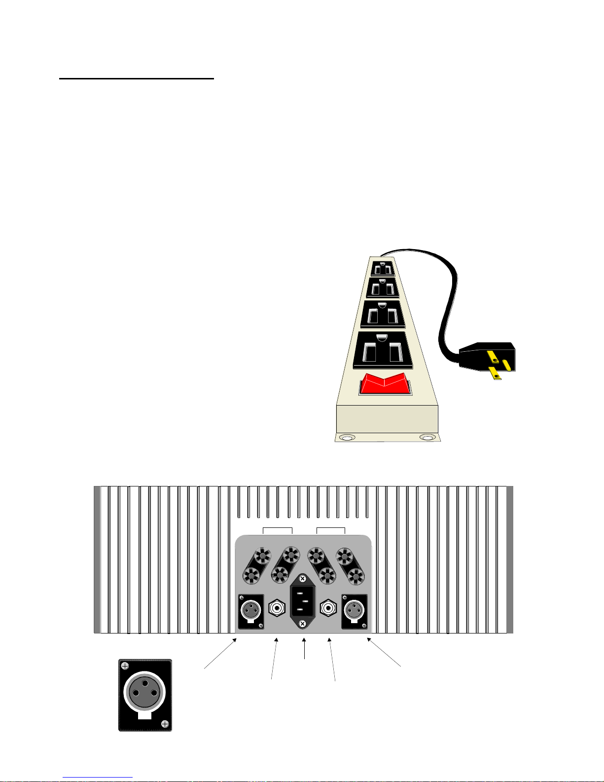
REAR PANEL
The two female XLRs are pre-amplifier inputs. Also, phono input sockets are available immediately outboard of the
IEC mains plug. Please connect these last, with the amplifier switched off.
It has come to light that, in some European
countries a hum may occur if Pre and Power
Amplifiers are connected to mains wall sockets
which do not have an earth. Please ensure
that, if this is the case, the pre and power
amps are connected via a multi-way mains
block which contains an earth point at each
socket outlet. This is to ensure that the chassis
metalwork of each item is connected together
and Chord Electronics Limited firmly
recommend that an earthing method for the
building is implemented.
3
21
PUSH
Left
Balanced
Input
Pin 1 Earth
Pin 2 +ve
Pin 3 –ve
Mains
Input
Right
Balanced
Input
Pin 1 Earth
Pin 2 +ve
Pin 3 –ve
Left
Input
Phono
Socket
Right
Input
Phono
Socket
PUSH
3
21
LEFTRIGHT
BLACK
RED
3
21
PUSH
A B A B
 Loading...