

Chord MU25, MU49, MU61 User Manual
MU-series MIDI/USB Keyboard Controllers
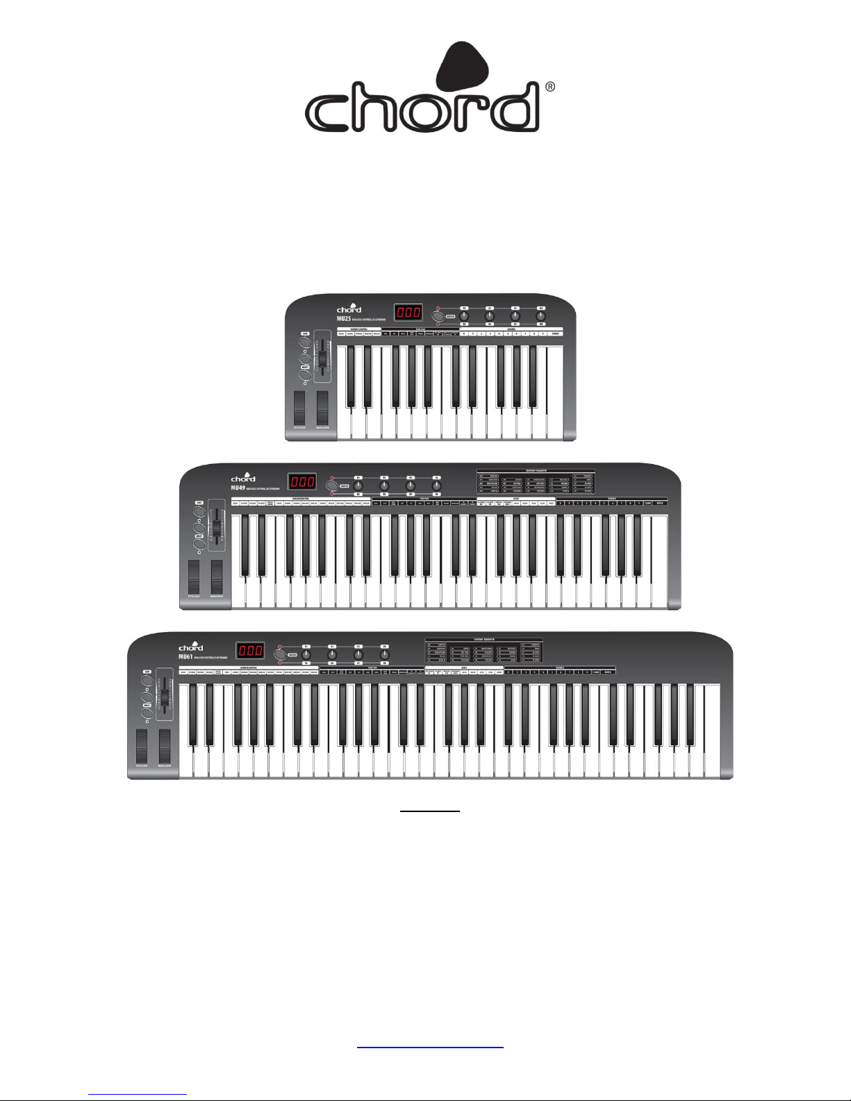
MU25 25-note MIDI/USB Controller Keyboard (169.011)
MU49 49-note MIDI/USB Controller Keyboard (169.012)
MU61 61-note MIDI/USB Controller Keyboard (169.013)
User Manual
Features
25/49/61 keys with touch velocity sensitivity (5 x velocity curves and selectable keyboard split)
Assignable control pedal (switch or continuous) inputs (1 for MU25, 2 for MU49 & MU61)
Assignable slider control
Pitch Bend Wheel and Modulation Wheel (assignable)
4 x assignable rotary controls (2 banks) and 2 data entry buttons
MIDI and USB output (powered by 9Vdc or USB)
Compatible with Win XP/Vista and Mac OSX, plug-and-play, hot swappable
Compatible with major audio and sequencer software
www.chordmusic.co.uk

Introduction:
Thank you for choosing a Chord MU series MIDI/USB controller. This product has been designed to give ultimate control over
MIDI sound modules and soundcards and form a key part of any project studio or live multi-instrument set-up. Please read the
following to get the best from your keyboard controller and avoid damage through misuse.
Warning:
To prevent the risk of fire or electric shock, do not expose any of the components to rain or moisture.
If liquids are spilled on the surface, stop using immediately, allow unit to dry out and have checked by qualified personnel before
further use.
Avoid impact, extreme pressure or heavy vibration to the unit.
There are no user serviceable parts inside the keyboard – refer all servicing to qualified service personnel.
Safety
When using an optional DC adapter to power the keyboard, ensure that it is a regulated type with correct voltage & polarity
Use only good quality USB and MIDI leads
Only connect standard foot switch or expression pedal to the rear jack inputs.
Do not allow any foreign particles to enter the keyboard through connectors or control apertures
Placement
Position the keyboard on a solid, flat surface or strong, stable keyboard stand with adequate grip to hold steady
Keep out of direct sunlight and away from heat sources.
Keep away from damp or dusty environments.
Ensure cables and power supplies are kept tidy and away from harm
Cleaning
Use a clean dry cloth (or slightly damp) to clean surfaces.
Use a soft brush to clear debris from between the keys
Do not use strong solvents for cleaning the unit.
Functions
The keyboard is velocity sensitive with additional functions labelled above each note key.
This additional function is accessed by the EDIT button.
When EDIT is pressed, the keyboard provides functions as labelled above each note key, including Program Adjustment, Dual,
Touch Sensitivity Adjustment, Numerical values etc. (the range of functions varies by model)
In addition to the note keys, the MU-series keyboards have a set of controllers for setting parameter values or offering
expression (creative changes/variances of the sound) for on-the-fly effects
Furthermore, control pedals can be connected to the input(s) on the rear panel for even more expression control
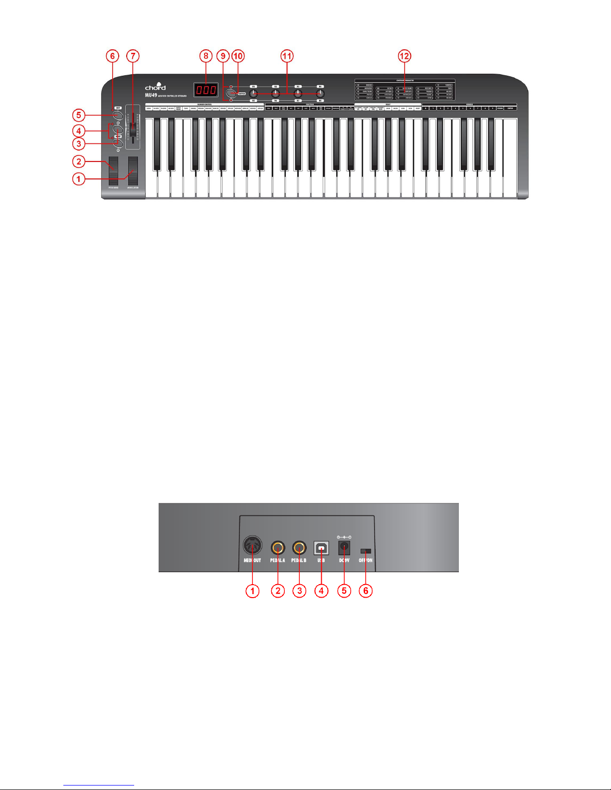
Top Panel
1. MODULATION Wheel - Expression wheel, assignable to one of 148 MIDI control parameters. Initial setting is MIDI
control number 1: Modulation.
2. PITCH BEND Wheel – Spring loaded expression wheel, assignable to one of 148 MIDI control parameters. Initial
setting is MIDI control number 146: Pitch Bend
3. DATA +/- Buttons – Increment/decrement data entry buttons, assignable to one of 160 MIDI control parameters. Initial
setting is MIDI control number 154: Octave Shift
4. OCTAVE/TRANSPOSE Indicator - When either of these indicators is on, it indicates that there is an upper/lower
octave shift. When the indicator flashes slowly, it indicates that there is an upper/lower transpose shift. When the
indicator flashes quickly, it indicates that there is a simultaneous upper/lower octave and transpose adjustment. When
the indicator is off, there is no octave or transpose shift.
5. EDIT Button – Switches edit function of note keys on/off
6. EDIT Indicator – Indicates that the EDIT function is active (keys will operate as labelled above each note)
7. SLIDER – Fader style controller, assignable to one of 148 MIDI control parameters. Initial setting is MIDI control number
147: Master Volume
8. 3-digit LED Display – Shows program/parameter values for MIDI and EDIT functions
9. SWITCH Button – Toggles the rotary dials between 2 groups of control settings: R1-R4 / R5-R8
10. Dial Function Group LEDs – Indicate which group of parameters is active for rotary dials.
11. R1- R8 Dials – 4 data entry dials, individually assignable to one of 160 MIDI control parameters, divided across 2
groups. Initial channel of R1-R4 is 0. Initial controller numbers are 152, 153, 156, 157, which control Program, Channel,
Tempo and Keyboard Velocity Curve respectively. The initial channels of R5-R8 are 0-3. Initial controller number is 7,
which controls the volume of channels 0-3 respectively. The parameter group of R1-R4 and R5-R8 is switched by the
SWITCH button.
12. Constant Controller Parameter chart – A table showing standard MIDI parameter values
Rear Panel
1. MIDI OUT – 5-pin DIN MIDI output to control external sound module or keyboard
2. PEDAL A – Pedal A input 6.3mm jack for switching or continuous type pedal control, assignable to one of 152
controllers. Initial setting is Soft Pedal.
3. PEDAL B – Pedal B input 6.3mm jack for switching or continuous type pedal control, assignable to one of 152
controllers. Initial setting is Sustain Pedal.
4. USB – USB type B connector for connecting to PC or Mac computer
5. DC9V – Input jack for optional 9Vdc power adapter (300mA, polarity positive-to-centre)
6. OFF/ON – Power switch
 Loading...