

Page 1
Please store this instruction
manual in a designated place for
futur
e reference.
INST.No.TPL-02-5A
TP
TPTP
TP-LLLL0260
02600260
0260EN
ENEN
EN
Instruction Manual
CHINO
INSTRUCTION
S
Compact
Thermal Image Sensor
Page 2

Page 3
I
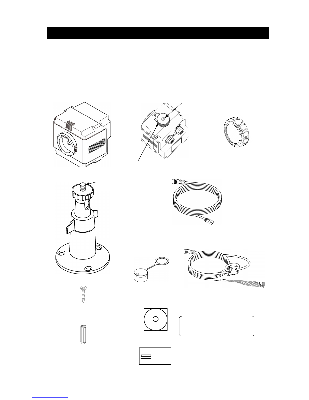
Custom Network Cable
(With a crossing cable and an RJ-45 terminal) 2.5m: 1 piece
* For direct connection to PC
(Refer to Page 6 for details.)
Custom Power/Alarm Output Cable
(With O-tip terminals) 2.5m: 1 piece
Introduction
Thank you for purchasing a compact thermal image sensor. In order to use this product
safely, please read this instruction manual completely before use and confirm the correct
handling and instructions. In addition, please retain this instruction manual for future
reference.
Before using
Please confirm the contents of packing. If something is missing, please contact to your nearest distributor.
.
Thermal image sensor
Carl plugs for mounting
the universal head
into concrete: 3 pieces
Connector cap: 1 piece
Lens cap: 1 piece
Universal head: 1 piece
Screws for the universal
head: 3 pieces
Mounting screw: 1 piece
This is attached to the sensor
Screw size
1/4-20UNC
Screw size
1/4-20UNC
CD-ROM: 1 piece
Application software
Instruction manuals (For the
sensor and the application
software
Quick manual: 1 sheet
Page 4

II
This product corresponds to Items 10 (2) and 10 (4) of Export allowable items listed in
Appendix No. 1 of the Export Trade Control Ordinance in Japan.
When this product is exported or brought out of Japan, the permission by the Japanese
government is required under this control ordinance.
About this instruction manual
Under absolutely no circumstances may the contents of this instruction manual, in part or
in whole, be transcribed or copied without permission.
The contents in this instruction manual are subject to change without notice in future.
The figures in this instruction manual may be emphasized, simplified or omitted.
Every effort has been made to ensure that the details of this manual are accurate.
However, should any errors be found or important information be omitted, please inform
your nearest distributor.
“Microsoft” and “Windows” are either trademarks or registered trademarks of Microsoft
Corporation, USA.
The company names and brand names used in this manual are the trademarks or
registered trademarks of respective companies.
About exemption from responsibility
Unless otherwise specified in the guarantee clauses, we do not offer any guarantee about
this product.
We shall not be liable to a customer or a third party for any damages or indirect damages
by using this product or by unpredictable defects of the product.
Page 5
III
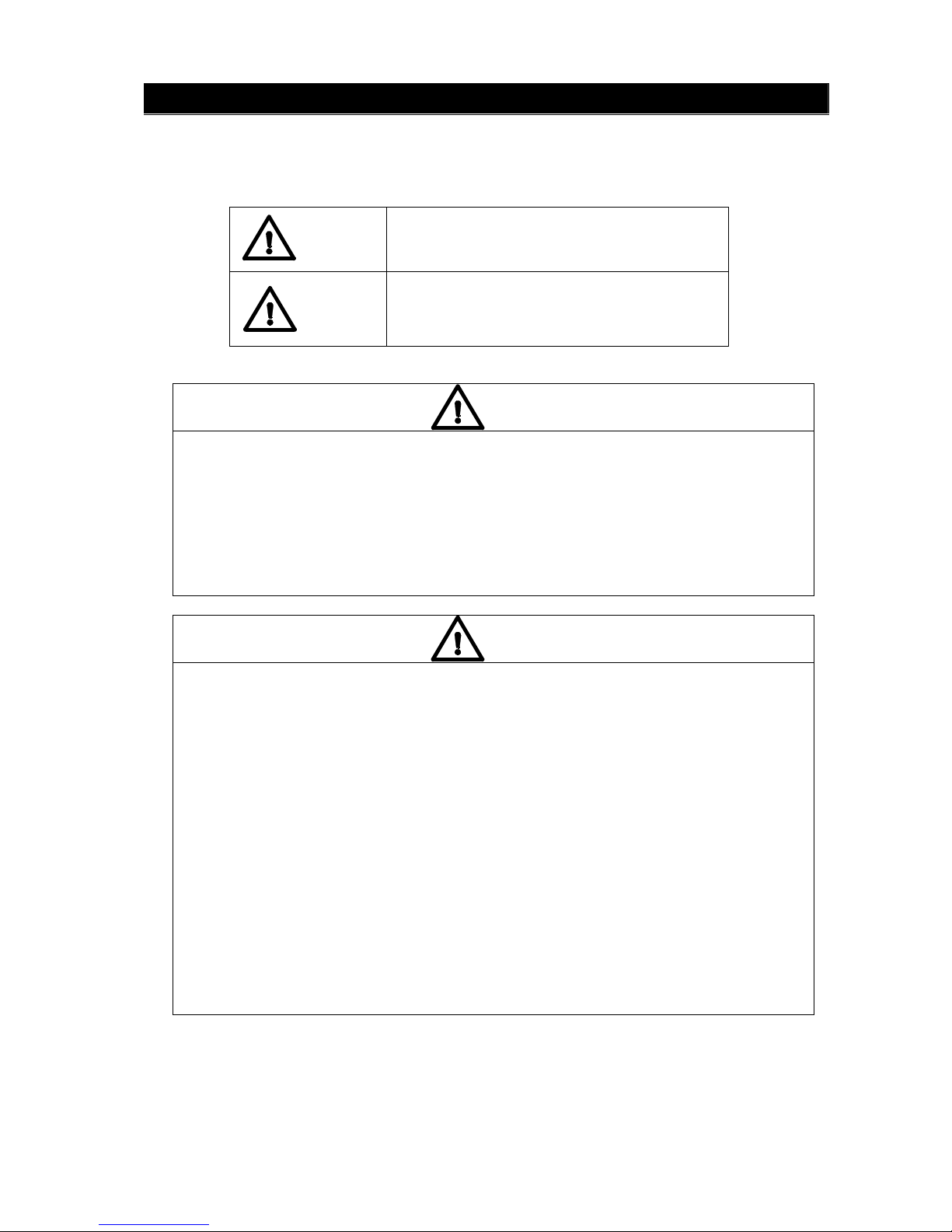
Safety precautions
The safety precautions shown in this manual indicate the important contents about safety.
Please be sure to understand and follow these precautions.
In this manual, in order to use this product safely, the precautions are described with the
following indications and marks.
This indicates a potentially hazardous
situation that, if not avoided, will result in
death or serious injury.
This indicates a potentially hazardous
situation that, if not avoided, may result in
minor or moderate injury or cause property
damage.
[Safety precautions]
Do not operate this product in a place where flammable gas or explosive gas exists. It is
extreely dangerous to use this product under such environment.
In order to prevent an electric shock, make sure that the power source is turned off before
connecting any wiring.
● Stop using this product immediately, turn off the power source and contact to
your nearest distributor if it is broken or there is smoke/abnormal odor from this
product. Otherwise, it may cause fire.
● Do not repair or modify this product. If it is modified, operation of this product will not
be guaranteed. It may also cause fire/electric shock.
● Avoid the use of this product in the following places.
A place where ambient temperature varies widely
A place where humidity is high
A place where rain/water is splashed
A place where there are dusts like sand or dirt
A place where it is subjected to exposed in scorching heat or direct sunlight
A place where it s subjected to radiation
A place where strong electric circuit exists beside this product
A place where there is any inductive interference
A place where there is mechanical vibration/shock
● If this product is wired with wrong polarity, it may cause trouble or fire.
● Do not aim the sensor to a high temperature object like sun, or the imaging element
may be damaged and it may cause trouble on this product.
● In order to use this product safely, refer to "requirements" and handling methods
mentioned in this manual or it may cause damage or malfunction to this product or
cause damage also to other equipments.
● Optical components have special coating. Be careful that these parts become easily
dirty when they are dew-condensed. In addition, the infrared transmission is
deteriorated under the dew condensation and a clear image is not provided.
Warning
Caution
Warning
Caution
Page 6

IV
When you use accessories connected to this product, follow the instructions relating
toregarding the safety in this manual. If you do not follow these instructions, safety of this
product and the system will not be guaranteed.
Your extra consideration is required when this product is used in an application that may
subject to life threatening to human or property damage. Pay extra attention to safety
measures, avoid usage under extreme environment and build a fail-proof system.
Precautions for use
This product is a precision instrument. Do not drop it or make a strong impact on it.
Do not use it in water.
Keep this product away from equipments generating strong static electricity and
electromagnetic waves including TVs, microwave ovens and wireless applications, or it may
cause malfunction or trouble on this product.
Keep this product away from equipment generating strong high frequency or surge voltage,
or it may cause malfunction or trouble on this product.
Use neutral detergent for cleaning of this product and wipe it off lightly by rubbing with the
cloth squeezed firmly. Do not use chemicals or bleaches including benzene, thinner and
alcohol.
Do not use or place this product in a place subjected to temperature of lower than -10°C or
higher than 50°C, dew-condensation, or humidity of lower than 10%RH or higher than
80%RH.
Do not use or place this product in a place subjected to direct sunshine, dusty, high
temperature/high humidity or corrosive atmosphere.
When any service including repairs is required, contact to your nearest distributor.
Do not apply too much force on the custom power supply and Network cables. It may cause
damage of the connection which may lead water immersion into the product, and may cause
trouble on this product.
Page 7

【準備・設定編】 Contents
■ Introduction ......................................................... I
■ Safety precautions .............................................. III
■ Precautions for use ............................................ IV
■ Outline of product
1. Configuration........................................... 1
2. Features ............................................... 1
3. Functions ............................................. 1
4. Model/specification.................................. 1
5. Basic configuration ……………………… 2
■ Names and functions ........................................... 4
■ Connection .......................................................... 5
■ Installation ........................................................... 7
■ Operation ............................................................. 8
■ Monitor lamp ........................................................ 8
■ Operation mode...................................................... 8
1. Monitor mode........................................... 8
2. Capture mode ...................................... 8
■ Alarm output ........................................................ 9
■ About reset switch ................................................. 11
■ Specifications ...................................................... 12
■
Precautions (For maintaining measurement accuracy)
......... 14
■Troubleshooting ………........................................ 14
■ External dimensions
1. Thermal image sensor............................ 15
2. Universal head........................................ 15
3. Protective case....................................... 16
Page 8

1
Outline of product
1. Configuration
The system consists of the thermal image sensor utilizing a thermopile array detector and the
application software for displaying thermal images converted from the temperature data from the
sensor..
The application software allows to connect up to 4 thermal image sensors and display thermal
image from these sensors.
2. Features
Built-in thermopile array detector with approximately 2256 pixels. Each pixel can measure
temperature.
Low cost, compact size and lightweight (150g) fixed-mount type thermal image sensor
Robust and dust/splash-proof construction IP-65
Data transmission to a PC via Ethernet (LAN), Thermal image display by the application software
2 built-in circuits of non-voltage contact outputs. The sensor can be used as a fixed-mount type
alarm unit.
(When an alarm is activated, 1 image can be stored in the sensor.)
3. Functions
Alarm can be set from the application software or custom-made commands. The sensor provides
non-voltage contact outputs when the alarm condition is met.
Monitor mode (when the supplied application software is used)
The temperature data of the entire thermopile array can be obtained continuously from the PC.
Capture mode (when the supplied application software is not used)
The temperature data in a single row of the thermopile array can be obtained at a time by a
command from a master unit (e.g. PC or PLC).
When the capture mode is used, a series of communication command is required.
For the communication commands, contact to your nearest distributor.
4. Model/specification
TP-L
□□ □□ □ □
Pixels 02: 2256
View angle 60: 60°
Output E: Alarm + LAN
Specification N: Standard specifications
Page 9

2
DC power supply
(DC12V 1.5A)
5. Basic configuration
5-1. Connection with 1 Thermal Image Sensor to PC (Monitor mode)
5-2. Connection of multiple Thermal Image Sensors (Example: 2 units)
Supplied custom Network cable (Crossing cable)
Custom power/alarm output cable
Power voltage: 12/24VDC
(Min. 9 ~ Max. 30VDC)
(Refer to Page 12 for details.)
PC
Alarm setup or
monitor with the
PC
Alarm contact
outputs from the
thermal image
sensor
LAN
Contact output
* If a HUB without automatic crossing/straight converting function is used, a straight
cable is needed. Connect a crossing/straight converting connector between the custom
Network cable and a HUB. (Refer to Page 3.)
Alarm setup or
monitor with the
PC
Alarm contact outputs
from the thermal
image sensor
Alarm contact outputs
from the thermal
image sensor
Thermal image sensor
PC
Thermal image sensor
DC power supply
(DC12V 1.5A)
DC power supply
(DC12V 1.5A)
Contact output
Contact output
LAN
LAN
HUB (*)
Monitor mode (when the supplied application software is used)
The temperature data of entire thermopile array can be obtained from the PC.
Thermal image sensor
Page 10

3
DC power supply
(DC12V 1.5A)
Connection example of HUB (without automatic crossing/straight converting function)
5-3. Stand alone usage of the thermal image sensor
5-4. Connection to PLC (Capture mode)
When the capture mode is used, a series of communication commands are required.
For the communication commands, contact to your nearest distributor.
Custom Network cable (Crossing cable)
HUB
Crossing/straight converting connector
LAN cable (Straight cable)
PC
Alarm contact output
from the thermal
image sensor
For image confirmation and alarm settings only
LAN
Contact output
Contact output
Other alarming devices
PLC
Capture mode (
when the supplied CHINO application software is not used)
The temperature data in a single row of the thermopile array can be obtained
at a time
by a command from a master unit (
e.g. PC or
PLC
).
LAN
DC power supply
(DC12V 1.5A)
Page 11

4
(7)
Names and functions
(1) Monitor lamp
(2) Lens
(4) (5)
Power/alarm output LAN connector
connector
(3) Mounting screw (6) Reset switch
(Behind the screw)
No Name Function
(1) Monitor lamp
The state of alarm and the condition of the sensor is indicated
with colors of blue, red and purple. (Refer to Page 8.)
(2) Lens
For forming image of radiation energy from a measurement
object on the detecting element
(3) Mounting screw For mounting the sensor on a tripod (1/4-20UNC)
(4)
Power/alarm output
connector
For connecting custom power/alarm output cable
(5) I/F connector For connection of custom Network cable
(6) Reset switch
To initialize the sensor to factory default (The switch is located
behind the mounting screw.) (Refer to Page 11 for details.)
(7) Mfg nameplate Serial No., MAC address, etc. are shown.
Page 12

5
[] mark
Connection
● Connect the custom power/alarm output cable and the custom Network cable to this product.
Connect them to align the marks of [] back of this product and [Arrow] on the cable connectors.
To avoid misconnections, the custom Network cable is designed not to connect to the
power/alarm output connector of this product. Similarly, the custom power/alarm output cable
cannot be connected to the LAN connector of this product.
The connections are a quick-disconnect locking type. Insert the plug until it clicks.
To unplug, hold the sliding part (that has the [Arrow] marking on) and pull it outward.
If the “A” part is pulled, and the plug may be damaged.
.
● Plug the connector of the custom Network cable to the Ethernet port of a master unit (PC, etc.)
and connect the O-tip terminals of the custom power/alarm output cable to the terminal block
of
12VDC Power Supply.
Custom Network
cable LAN connector
Custom power/alarm output
cable ring terminals
Insulate the O-tip alarm output
terminals if not used.
[Arrow] mark
LAN port
Terminal block
Plug
A
Page 13

6
[Alarm 1, w/ AC current] [Alarm 1, w/ DC current]
(AC)
(Relay)
(DC)
(Relay)
Connector cap
[Details of custom power/alarm output cable] O-tip terminal 0.5-3.5
Power +
Power -
Alarm 1 +
Alarm 1 -
Alarm 2 +
Alarm 2 -
[Example of contact output circuit]
Use the contact output with a protection device (e.g. fuse) for preventing malfunction.
Max. output load voltage 400V (Peak AC)
Max. continuous load current 0.1A (Peak AC)
Peak load current 240mA (100ms/1 shot)
Output capacity (Per 1 contact)
Max. output loss 300mW
● If the custom Network cable is not used (When using the thermal image sensor stand alone)
Cover the supplied connector cap to the connector marked with [LAN] back of this product.
If you don’t cover the connector with the cap, the waterproofing performance cannot be
satisfied. (It may cause water immersion.)
Red
P +
Black
AL1 +
Orange
AL1 -
Pink
AL2 +
Bright
green
AL2 -
Blue
P -
AL1 +
AL1 -
AL1 +
AL1 -
Power
Power
Page 14

7
Installation
By referring the figure below, install the thermal image sensor at the measuring distance that a
measuring object can be imaged at the center of screen as large as possible.
<Relation between a measuring surface and a measuring distance>
D (View width) = 1.4 × L (Measuring distance)
For accurate measurements, 8 x 8 pixels or more for a target is recomended.
1.4m
Do not install the sensor where subjected to vibration/shock or inductive ambient.
1m
3m
5m
29mm
4.2m
88mm
146mm
7.0m
: View per pixel
Page 15

8
Operation
● Install the supplied application software to your personal computer.
(For the details, refer to the instruction manual for the application software.)
● For more accurate measurements, wait 30 minutes after power-on until this product is stabilized.
● Use this product with noiseless and stable power source.
Monitor lamp
The state of product is indicated by 3 colors on the LED indicator; blue, purple and red.
Item Color Specification
Mode is not set (Factory Default) Blue Lit once for 3 seconds
Alarm values are not set Blue Lit once for 3 seconds
Alarm being monitored Blue Lit continuously
Set to Captured Mode Purple Lit continuously
Reboot is required after all settings have
completed
Purple
Lit for 3 seconds twice
Alarm is activated Red Lit continuously
Abnormal internal memory Red
Lit once for 3 seconds
* Refer to Page 14 Troubleshooting.
Abnormal
State
Abnormal internal temperature Red
Lit once for 3 seconds
* Refer to Page 14 Troubleshooting.
Operation mode
1. Monitor mode: When CHINO application software is used
The temperature data is sent continuously to a master unit (e.g. PC) by a command from the
software.(The frame rate of the thermal image on the software is 3fps without any Alarm activated.)
The alarm set on the sensor can provide a non-voltage contact output while sending the
temperature data.(The frame rate goes down to 1fps or less with the alarm set on the sensor.)
2. Capture mode: Without CHINO application software
The temperature data in a single row of the thermopile array can be obtained at a time by a
command from a master unit.
When Capture mode is used, a series of communication commands are required.
For the communication commands, contact to your nearest distributor.
Page 16

9
Alarm output
1. Specifications
Item Specification
Alarm area 1 area
Alarm set value 2 values in a specified area
Setting resolution 1 degree (°C/ºF)
Alarm activation condition
When consecutive 4 frames have satisfied the alarm
condition
Alarm reset condition
When the measured temperature returns from the
alarm set value in 4 images continuously
Output Control Auto Alarm Reset/Manual Alarm Reset
Resetting condition of alarm
output manual reset
Rebooting of the thermal image sensor
Command from a PC
Alarm Output Non-voltage contact output
Number of outputs 2 points [Alarm name: AL1 (alarm 1), AL2 (alarm 2)]
Output logic Output logic selectable (N.O/N.C)
Alarm condition Selectable (high-limit, low-limit)
Alarm condition when power is off Opened
2. Image storage
The image data can be stored when alarm is activated.
Item Content
Number of storage
1 image
An image can be stored by AL1 or AL2 (to be
specified).
Storage medium Built-in EEPROM
Storage data Temperature data (without time stamp)
Storage timing
Every time when the alarm is activated/when the first
alarm is activated only
Selectable by a PC (Refer to Page 10.)
Reading of stored data Can be retrieved from a PC
Erasing of stored data
Automatic erasing or erasing by a command with the
alarm setting from a PC
Page 17

10
警報有
警報有警報有
警報有 警報無
警報無警報無
警報無
警報状態
警報状態警報状態
警報状態
警報出力
警報出力警報出力
警報出力
警報出力
警報出力警報出力
警報出力
画像保存
画像保存画像保存
画像保存
画像保存
画像保存画像保存
画像保存
警報状態
警報状態警報状態
警報状態がががが連続
連続連続
連続でででで発生
発生発生
発生した
したした
した場合
場合場合
場合はははは、、、、発発発発
生時
生時生時
生時のののの最初
最初最初
最初のののの画像
画像画像
画像をををを保存
保存保存
保存する
するする
する
画像上書
画像上書画像上書
画像上書きききき
警報有
警報有警報有
警報有
熱画像
熱画像熱画像
熱画像センサ
センサセンサ
センサのののの電源再投入
電源再投入電源再投入
電源再投入又又又又はははは上上上上
位位位位機器
機器機器
機器からの
からのからの
からのコマンド
コマンドコマンド
コマンドまで
までまで
まで受信
受信受信
受信まで
までまで
まで
保持
保持保持
保持する
するする
する
自動復帰
自動復帰自動復帰
自動復帰
保持
保持保持
保持
● Alarm output and storing image
熱画像
熱画像熱画像
熱画像センサ
センサセンサ
センサのののの電源再投入又
電源再投入又電源再投入又
電源再投入又はははは
アプリケーションソフト
アプリケーションソフトアプリケーションソフト
アプリケーションソフトからの
からのからの
からの
警報解除
警報解除警報解除
警報解除まで
までまで
まで保持
保持保持
保持する
するする
する
Alarm state
Auto Reset
Contact output
Image saving
ON
OFF
ON
Image is overwritten.
Manual Reset
Contact output
Image saving
The image is saved only at the time
of when alarming state turns from
Off to On.
Contact output state will be held until
the sensor restarts or you reset the
alarm by clicking [Alarm Reset] button
in Alarm Setup Window.
Page 18

11
Reset
switch
Reset switch
(behind the screw)
Remove the mounting
■ About reset switch
In case of an error, etc. at the LAN environment settings, the set values can be reset to the default
values as shipped from factory by removing the mounting screw and then pushing the reset switch.
Turn the power on while pushing the reset switch for 1 second continuously. Resetting to the
default values becomes effective (The violet monitor lamp flashes 2 times.) By re-power-on,
the set values are reset to the default values at the shipment from factory. Usually do not push
the reset switch.
[Factory Default settings]
Items Specifications
IP address 192.168.1.254
Subnet mask 255.255.255.0
Gateway address 0.0.0.0 (Invalidation)
Sensor number 1
UDP port address 50828 (fixed) *1
Emissivity 1.00 (all pixels)
Alarm setting Alarm invalid
*1
If you use UDP port on your PC and the UDP port address that you are using is
overlapping with this address, change the UDP address that you are using
.
[MEMO]
Page 19

12
■ Specifications
Items Specifications
Detecting element Thermopile array with 48 x 47 pixels
Measurement wavelength Center wavelength 10µm
Measurement view angle 60° x 60°
Temperature measurement
range
-20°C to 300°C
Temperature resolution 0.5°C (at 100°C black body)
Accuracy ratings
±2% of measured value or ±3
°C, whichever is greater
(Ambient temperature 25 ± 2
°C)
Focus Fixed focus
Flame rate 3fps (1fps or slower if alarm function is enabled)
Emissivity correction 0.10 ~ 1.00 (0.01 increment)
Radius resolution 21.8mrad
Working temperature range -10°C to 50°C
Working humidity range 10 to 80%RH (no dew condensation)
Storage temperature range -20°C to 60°C
Housing
IP65 (with custom
cable connection or connector cap, and
mounting screw mounted)
External dimensions W62 x H62 x D59 (mounting screw not included)
Weight About 150g (sensor unit)
Material
Polycarbonate Resin Color: Black
Conforming standard
Influence within 3% of measurement range under the
environment of CE (EN61326-1/Class B)
mounting screw size 1/4-20UNC
Power supply 12 to 24VDC (Min. 9 to Max. 30VDC)
Current consumption *1 Max. 2.5VA at 12VDC
Inrush current *1
Max. 1A at 12VDC
(When power supply S8VM-01512 made in Omron is
used)
Connection Custom-connector connection
Connector name [DC IN/IN/OUT]
*1
The inrush current should be considered for the selection of power source.
Thermal image specifications
General specifications
Power specifications
Page 20

13
Items Specifications
Number of contact output 2 Outputs
Kind of contact No-voltage contact output
Cable terminal names AL1, AL2
Max. output load voltage 400V (Peak AC)
Max. continuous load current 0.1A (Peak AC)
Peak load current 240mA (100ms/1 shot)
Contact Rating (per
contact)
Max. output loss 300mW
Connection Custom-connector connection
Connector name [DC IN/IN/OUT]
Interface standard 10BASE-T/100BASE-TX
Data/Protocol
Data communication by UDP
Measured temperature data → To a master unit (PC, etc.)
Setting data ← From a master unit (PC, etc.)
Setting data IP address/alarm setting information, etc.
DHCP
Not supported
Thermal image sensor IP
address
192.168.1.254 (default at shipment)
Thermal image sensor
subnet mask
255.255.255.0
Default gateway 0 or FFFF (Not set)
Connection Custom-connector connection
Connector name [I/F]
■ Accessory (sold separately)
Protective case: Model: TP-ZCC1 (Refer to Extrernal Dimension.)
■ Minimum requirements for the CHINO application software
Compatible PC: DOS/V computers with PC/AT compatible
* The LAN port is required.
* Display resolution: 800 x 600 pixels or more recommended
* .NET Framework 2.0 or later has been installed and runs correctly.
Compatible OS: Windows 2000 (SP4 or later)/XP/Vista
* Windows XP or later recommended
* .NET Framework 2.0 or later required
Contact output specifications
Ethernet specifications
Page 21

14
Precautions (For maintaining measurement accuracy)
Pay attention to the followings for maintaining the measurement accuracy.
Vibration and shock
Vibration and shock causes not only a damage to the thermal image sensor in a long term but in
stability of the measurement. When vibration is present, anti-vibration/shock absorber may be
required between the thermal image sensor and a mounting plate or between the mounting
bracket and a mounting plate.
Inductive condition
The thermal image sensor is designed to be inductivity-resistant. However, it is recommended to
keep the sensor from induction heaters or power lines as much as possible.
IR energy path between measuring targets and the sensor
Avoid places where water drops, dusts, smoke, steam, etc. can be present between the thermal
image sensor and a measurement surface. If it is impossible to avoid such places, consider
utilizing an air purge system or equivalent system. The optional protective case is recommended.
Disturbances causing higher temperature indication
Avoid places where high temperature heat source such as sunlight, light/flame of incandescent
electric lamps is not reflecting on a measurement surface and the thermal image sensor. If such
condition is present, cover the area with an opaque object.
■ Troubleshooting
If you are experiencing difficulties with the sensor or noticing an abnormality on its operation, refer
to the followings. If the difficulties or abnormality is still present, contact to your nearest distributor.
Symptoms Causes Measures
The custom power cable is
not connected properly.
Connect the custom power cable
properly.
Indicator lamp is
not lit
The power for equipment is
not turned on.
Turn the power for the equipment.
The custom Network cable is
not connected correctly.
Connect the custom Network cable
properly.
The application software is
not installed.
Install the software.
Refer to the instruction manual for the
application software.
No
Communications
The IP address has not been
set.
Refer to the instruction manual for the
application software.
Image/temperature
value abnormally
fluctuates.
Strong statistic electricity,
electromagnetic wave or high
frequency may be present
around the sensor.
Keep this product away from an
equipment generating strong static
electricity or electromagnetic wave.
Indicator lamp
is
red
Alarm is activated (Not
abnormal)
Automatic reset: Resets automatically.
Manual reset: Resets by re-boot or a
command from a master unit (PC,
etc.).
Indicator lamp
flashes red once
Internal memory abnormality Contact to your nearest distributor.
Indicator lamp
flashings red twice
Internal temperature
abnormality
Use this product within its operating
temperature range.
Contact to your nearest dirtributor.
Page 22

15
φφφφ58
5858
58
■External dimensions
1. Thermal image sensor
2. Universal head
When the thermal image sensor is installed with the universal head, mount the mounting bracket
with 3 pieces of screws through the 3 holes on the bracket. If the universal head needs to be
mounted on concrete surface, drill holes with 6.5mmø and 25mm depth on the concrete and push
the Carl plugs into the holes, and then mount the universal head.
Carl plugs
For mounting on
concrete
(The plugs are not
used for usual
installation.)
Screw size
1/4-20UNC
Page 23

16
3. Accessory
Protective case: Model TP-ZCC1
Hole for air purge (PT1/8)
 Loading...