


INST.NO. INE-846B
AL4000/AH4000
Hybrid Memory Recorder
KL4000/KH4000
Hybrid Recorder
[ Communication Interface ]

|
Table of contents |
|
1. Introduction.................................................................................................................... |
1 |
|
2. For Safe Use................................................................................................................... |
2 |
|
2-1. |
Preconditions for Use ......................................................................................................................................... |
2 |
2-2. |
Symbol Mark....................................................................................................................................................... |
2 |
3. Overview......................................................................................................................... |
3 |
|
3-1. |
RS232C Communication Interface ..................................................................................................................... |
3 |
3-2. |
RS422A/485 Communication Interface .............................................................................................................. |
3 |
3-3. |
Ethernet.............................................................................................................................................................. |
3 |
4. Communications Protocol ............................................................................................ |
4 |
|
4-1. |
MODBUS Protocol.............................................................................................................................................. |
4 |
4-2. |
PRIVATE Protocol............................................................................................................................................... |
4 |
5. Communication Specifications..................................................................................... |
5 |
|
5-1. |
MODBUS............................................................................................................................................................ |
5 |
5-2. |
PRIVATE............................................................................................................................................................. |
5 |
5-3. |
Ethernet.............................................................................................................................................................. |
5 |
6. Communication Parameter Settings ............................................................................ |
8 |
|
6-1. |
Ethernet Settings (AL4000/AH4000 Only) .......................................................................................................... |
8 |
6-2. |
COM Settings (For AL4000/AH4000) ................................................................................................................. |
9 |
6-3. |
COM Settings (For KL4000/KH4000) ............................................................................................................... |
10 |
7. Wiring............................................................................................................................ |
16 |
|
7-1. |
Precautions on Wiring ...................................................................................................................................... |
16 |
7-2. |
Communication Cable ...................................................................................................................................... |
17 |
7-3. |
Communication Line Wiring.............................................................................................................................. |
19 |
8. MODBUS Protocol ....................................................................................................... |
22 |
|
8-1. |
Message Transmission Mode ........................................................................................................................... |
23 |
8-2. |
Data Time Interval ............................................................................................................................................ |
24 |
8-3. |
Message Structure............................................................................................................................................ |
24 |
8-4. |
Message Creation ............................................................................................................................................ |
30 |
8-5. |
Function Code .................................................................................................................................................. |
31 |
8-6. |
Response to Abnormal Situation ...................................................................................................................... |
39 |
8-7. |
Title Printing (Message Printing 2) Function ..................................................................................................... |
41 |
8-8. |
Data Communications Input ............................................................................................................................. |
41 |
8-9. |
Reference Table ............................................................................................................................................... |
42 |
8-10. |
Range No. Reference Table ........................................................................................................................... |
104 |
9. PRIVATE Protocol (For AL4000/AH4000)................................................................. |
105 |
|
9-1. |
Basic Communication Sequence.................................................................................................................... |
106 |
9-2. |
Control Character Code.................................................................................................................................. |
106 |
9-3. |
Data Link ........................................................................................................................................................ |
106 |
9-4. |
Data Transmission and Reception.................................................................................................................. |
108 |
9-5. |
Checksum........................................................................................................................................................ |
111 |
10. PRIVATE Protocol (For KL4000/KH4000)............................................................... |
112 |
|
10-1. |
Basic Communication Sequence.................................................................................................................... |
113 |
10-2. |
Basic Communication Format......................................................................................................................... |
113 |
10-3. |
Control Character Code.................................................................................................................................. |
114 |
10-4. |
Communication Address................................................................................................................................. |
114 |
10-5. |
Checksum (bc bc)........................................................................................................................................... |
115 |
10-6. |
List of Sub Commands ................................................................................................................................... |
115 |
10-7. |
List of Error Codes.......................................................................................................................................... |
116 |
10-8. |
Communication Format Details ...................................................................................................................... |
117 |
11. Web Settings/Display (AL4000/AH4000 Only)........................................................ |
129 |
|
11-1. |
Top Page ........................................................................................................................................................ |
129 |
11-2. |
Display............................................................................................................................................................ |
130 |
11-3. Parameters Set by Each CH........................................................................................................................... |
131 |
|
11-4. |
Calculation...................................................................................................................................................... |
135 |
11-5. |
Dotting/Printing ............................................................................................................................................... |
137 |
11-6. |
Remote Contacts (Option) .............................................................................................................................. |
143 |
11-7. |
Communication............................................................................................................................................... |
145 |
11-8. |
SD Card.......................................................................................................................................................... |
149 |
11-9. |
System ........................................................................................................................................................... |
150 |

1. Introduction
Thank you for purchasing KL4000/KH4000 or AL4000/AH4000 series.
Make sure to read this instruction manual in advance to understand this unit well and prevent troubles from occurring.
This manual is a “Communications” instruction manual. For specifications with communications, read the “General” instruction manual separately.
Requestt
- To the persons doing instrumentation, installation, and sales -
Make sure to provide this instruction manual to the person who uses the unit.
- To the users of this unit -
Store this instruction manual with care until you scrap the unit.
Also, write down the parameter contents set in the product and keep it for your record.
Product warranty scope
This product is warranted for one year from the date of delivery. If it is damaged during the warranty period, when used normally based on the cautions in the instruction manual labels attached to the product, etc., it will be repaired without any charge (only in Japan). In the case, we are sorry to trouble you, but please contact your dealer or nearest our sales office.
However, in cases of the followings, it will be repaired at your expense even during warranty period.
1.Failure or damage caused by improper use or connection, or invalid repair or modification.
2.Failure or damage caused by fire, earthquake, wind or flood, thunderbolt, or other extraordinary natural phenomena, or pollution, salt, harmful gas, abnormal voltage, or use of unspecified power.
3.Replacement of parts or accessories that have reached the end of their life.
Furthermore, the term „warranty‟ in this sense covers only a CHINO‟s product itself. Therefore, we are not responsible for compensation for whatever the damage that is triggered by failure of our product.
Notice
1.No part of this manual can be reproduced or copied in any form without permission.
2.The contents of this manual may be altered without prior notice.
3.This manual has been documented by making assurance doubly sure. However, if any question arises or if any error, an omission, or other deficiencies are found, please contact your nearest our sales office.
4.CHINO is not responsible for any operation results of this software.
Trademark
1.Microsoft, Windows, Windows XP, Windows Vista, Windows 7, and NET Framework are trademarks of Microsoft Corporation and the related company.
2.SD Memory Card is the trademark of Panasonic Corporation, SanDisk Corporation in USA, and TOSHIBA CORPORATION.
3.Other described company names and product names are trademarks and registered products of the respective companies.
4.Please note that the marks “TM” and “®” are omitted throughout this manual.
Warning
Perchlorate Material
This instrument uses battery with Perchlorate Material.
Special handling may apply, see
http://www. dtsc.ca.gov/hazardouswaste/perchiorate
- 1 -

2. For Safe Use
For safe use of the unit, please read and understand the following cautions.
2-1. Preconditions for Use
The unit is a component type general product to be used mounted on an indoor instrumentation panel. Avoid using under other conditions.
Use after the system safety is implemented such as the fail-safe design and periodical inspection on the final product side. Also, for wiring/adjustment/operation of the unit, ask professionals with instrumentation knowledge to perform.
In communications interfaces, communication errors in some probabilities are unavoidable due to the timing and noise between instruments.
For your machines and devices, please perform retry processing, fail safe design, safety design and so on. Furthermore, also the person who actually uses the unit is required to read this instruction manual to fully understand various cautions and basic operation.
2-2. Symbol Mark
This instruction manual includes the following symbol marks. Make sure to fully understand their meaning.
|
Symbol mark |
Meaning |
|
|
|
|
|
|
! Caution |
|
Cautions are explained to avoid causes for slight injuries of users or damages of the unit |
|
|
or peripheral devices. |
|
|
|
|
|
- 2 -

3. Overview
The unit is equipped with the communication interfaces such as RS232C, RS422A, RS485 and Ethernet to communicate with a personal computer (PC). Receiving measured data, setting various parameters and sending operation commands can be performed on a PC.
The number of connectable units is one for RS232C, and 31 at maximum for RS422A/485.
3-1. RS232C Communication Interface
RS232C is a data communications standard developed and published by Electronic Industries Association (EIA), which is equivalent to JIS C 6361 of Japanese standard.
Originally, RS232C is an interface between a modem and connected data terminal equipment, and the standard specifies electrical and mechanical specifications only.
Currently, there are few RS232C communication interfaces used for PCs or industrial instruments like this unit which meet the above standard completely. There are cases where the number of signal cables or the connector differs from the standard.
Also, the standard does not specify software, or “data transmission procedure”, so it means that connection between devices with RS232C communication interface is not always possible. For this reason, users need to research or check the specifications and transmission procedures of devices to be connected beforehand. However, a device like PC which allows arbitrary programming of specifications can be combined with any device by creating an appropriate program.
To research the RS232C standards, referring to JIS C 6361 may be the easiest way.
3-2. RS422A/485 Communication Interface
With RS422A/485 communication interface, multiple units (up to 31) of this series can be connected in parallel to establish communication using signals conforming to RS422A/485.
There are not many PCs having RS422A/485 communication interface, however, serial communication enables easy connection setup using a signal converter between RS232C RS422A/485.
A line converter for RS232C RS422A/485 signal conversion (model: SC8-10) is available from us. Contact us when you need it.
The difference between RS422A and RS485 is that RS422A uses four signal cables whereas RS485 uses only two signal cables.
3-3. Ethernet
Ethernet is a communication interface standardized as IEEE802, 3 in 1983. It is widely used as the most common communication medium in small-scale LAN. The AL4000/AH4000 series is connected to LAN constructed by Ethernet to receive measured data or set various parameters.
- 3 -

4. Communications Protocol
The unit has the following two communications protocols which can be switched using the front keys.
4-1. MODBUS Protocol
MODBUS is a registered trademark of Schneider Electric.
MODBUS protocol has RTU mode and ASCII mode which can be selected using the front keys or via communication. This protocol provides measured data transmission, setting and operating functions.
For Ethernet interface, MODBUS protocol is implemented on TCP protocol packet to establish communication (see section 5-3).
4-2. PRIVATE Protocol
PRIVATE is a conventionally used protocol by CHINO.
This protocol can be selected using the front keys. It provides measured data transmission, setting and operating functions.
Two types of modes are available: PRIVATE1 and PRIVATE2, and these can be selected using the front keys.
|
KL4000/KH4000 |
AL4000/AH4000 |
|
|
|
PRIVATE1 |
No communication address |
No connection sequence |
|
|
|
PRIVATE2 |
Communication address |
Connection sequence |
|
available |
available |
|
|
|
PRIVATE1: With RS232C, data link is not necessary due to one-to-one communication with the host. Select PRIVATE1 for RS232C.
PRIVATE2: With RS422A and RS485, data link is required.
Select PRIVATE2 for these interfaces. Also, select PRIVATE2 for RS232C when the software of the host is shared since data link commands can be received.
The compatibility with our older models can be maintained. However, the parameters which cannot be handled by PRIVATE are now settable by MODBUS. We recommend MODBUS protocol to customers who construct a new communication environment.
- 4 -

5. Communication Specifications
5-1. MODBUS |
|
|
Communication system |
: |
Half-duplex start-stop synchronization |
Protocol |
: |
MODBUS protocol |
Transmission speed |
: |
9600, 19200, 38400bps selectable |
Start bit |
: |
1 bit |
Data length |
: 7 bits (ASCII mode) |
|
|
|
8 bits (RTU/ASCII mode) |
Parity bit |
: |
Non (None) /Even/Odd |
Stop bit |
: |
1 bit/2 bits |
Transmission code |
: |
ASCII (ASCII mode) |
|
|
Binary (RTU mode) |
Error check |
: |
LRC (ASCII mode) |
(Error detection) |
|
CRC-16 (RTU mode) |
Data transmission procedure |
: |
None |
Used signals |
: Transmitted/received data only (no control signal used) |
|
5-2. PRIVATE
Communication system |
: Half-duplex start-stop synchronization (polling selecting |
|
|
|
system) |
Protocol |
: |
PRIVATE protocol |
Transmission speed |
: |
1200, 2400, 4800, 9600bps selectable |
Start bit |
: |
1 bit |
Data length |
: |
7 bits/8 bits |
Parity bit |
: |
Non (None) /Even/Odd |
Stop bit |
: |
1 bit/2 bits |
Transmission code |
: |
ASCII |
Error check |
: |
BCC (block check character) checksum |
(Error detection) |
|
|
Data transmission procedure |
: |
None |
Used signals |
: Transmitted/received data only (no control signal used) |
|
5-3. Ethernet
Ethernet communication is supported by AL4000/AH4000 only.
Medium |
: |
Ethernet (10BASE-T/100BASE-TX) |
Communication mode |
: Full-Duplex/Half-Duplex |
|
Transmission speed |
: |
10Mbps (10BASE-T)/100Mbps (100BASE-TX) |
|
|
Note that transmission speed and communication mode are |
|
|
automatically recognized and cannot be set to fixed value. |
Protocol |
: |
MODBUS (RTU) protocol on TCP/IP |
Simultaneous connection |
: |
1 (in host communication using MODBUS protocol) |
The AL4000/AH4000 series provides a Web setting function on Ethernet (see section 11). The following table shows association with TCP/IP layers in MODBUS communication.
TCP/IP model layers |
Main protocol used in Ethernet communication |
Application layer |
MODBUS |
Transport layer |
TCP |
Internet layer |
IP, ARP |
Physical/data link layer |
Hardware (Ethernet) |
For details of MODBUS protocol, see “8. MODBUS Protocol”.
- 5 -
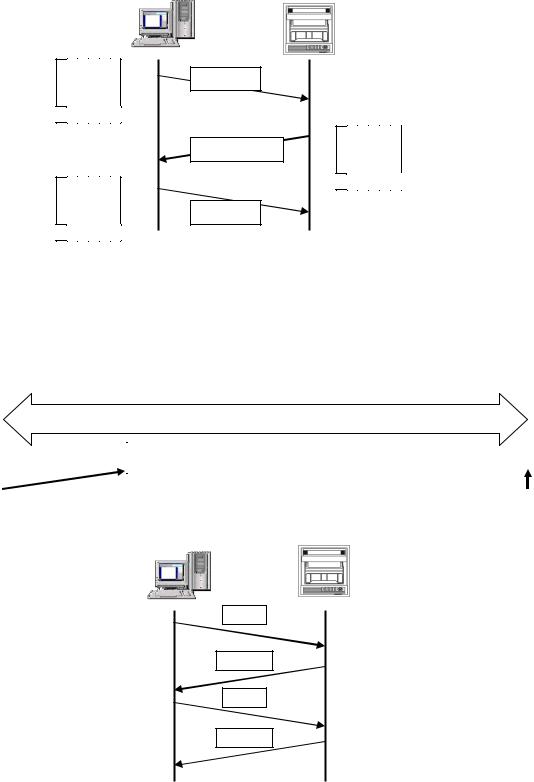
1. Establishing TCP connection
To establish communication between a PC (makes data request: client) and the unit (receives data request: server), establish TCP connection first according to the following procedure.
(1)PC sends a TCP packet with SYN flag set to the unit.
(2)When the unit receives the SYN packet, it sends a TCP packet with SYN + ACK flag set to the PC.
(3)When the PC receives the SYN + ACK packet, it sends a TCP packet with ACK flag set to the unit.
PC |
|
Unit |
Client |
|
Server |
|
|
|
|
|
|
U A P R S F R C S S Y I G K H T N N
0 0 0 0 1 0
U A P R S F R C S S Y I G K H T N N
0 1 0 0 0 0
(1) SYN
U A P R S F
(2) SYN + ACK R C S S Y I G K H T N N
0 1 0 0 1 0
(3) ACK
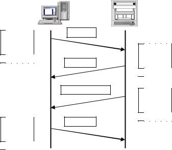
2. Transmitting/receiving data by TCP
Once the connection has been established, various data are transmitted/received between PC (client) and the unit (server) via MODBUS (RTU) protocol on TCP data.
|
|
|
|
TCP packet |
||
|
|
|
|
|
|
|
TCP header section |
|
|
|
TCP data section |
||
|
|
|
|
|
|
|
|
|
|
|
|
|
|
|
|
|
MODBUS (RTU) protocol |
|||
|
|
|
|
|
|
|
|
|
|
|
|
|
|
|
|
PC |
|
|
Unit |
|
|
|
|
|
|
|
|
Request
Response
Request
Response
- 6 -
3. Disconnecting TCP connection
TCP connection is disconnected with the following flow of communications.
(1)PC sends a TCP packet with FIN flag set to the unit (disconnection notice).
(2)When the unit receives the FIN packet, it sends a TCP packet with ACK flag set to the PC.
(3)The unit sends a FIN + ACK packet to the PC (disconnection notice).
(4)The PC sends an ACK packet responding to FIN to the unit.
PC |
|
Unit |
Client |
|
Server |
U A P R S F R C S S Y I G K H T N N
0 0 0 0 0 1
U A P R S F R C S S Y I G K H T N N
0 1 0 0 0 0
(1)FIN
(2)ACK
(3)FIN + ACK
(4)ACK
U A P R S F R C S S Y I G K H T N N
0 1 0 0 0 0
U A P R S F R C S S Y I G K H T N N
0 1 0 0 0 1
4. Actions against communication error
When the following communication errors occur on TCP/IP, the unit takes actions described below.
●No response from the device at the other end (PC, etc.)
When the unit sends data to a communication target on Ethernet but no response (ACK) packet is returned, the unit repeats transmission retry operation (for around three minutes maximum).
The unit disconnects TCP connection if no response is made to the transmission retry packet.
If a communication target makes a TCP connection request before the unit disconnects TCP connection, the unit sends an RST packet to reject the request.
The unit sends an RST packet in the following situations.
When a TCP packet is received from devices other than that being connected.
When an RST packet is received from a communication target.
●Unexpected reply packet received
Generally, unexpected reply packets are ignored. However, TCP connection is disconnected immediately after the unit receives an RST packet in situations such as when PC performs a forced disconnection of TCP connection.
- 7 -
6. Communication Parameter Settings
6-1. Ethernet Settings (AL4000/AH4000 Only)
(IP Address etc… Settings)
Set each parameter.
(1) Pressing the  key displays the menu window (list of setting items).
(2) Select “Ether”.
(3) |
Move the cursor to the parameter to be set |
||||
|
with the ▲/▼// keys. |
|
|||
(4) |
Press the |
key to make it available |
|||
|
for setting and then select or enter a value. |
||||
(5) |
After completing the settings of this item, |
||||
|
|
|
|
|
|
|
move the cursor to |
|
Set |
. |
|
(6) |
Press the |
key to register the |
|||
|
settings (when chart recording is ON, a |
||||
|
setting change mark is printed). To cancel |
||||
|
the settings, press the |
key. |
|||
Note: Actual windows are separated. Use the ▲/▼ keys to scroll and continue settings. [List of Ether setting parameters]
Parameter |
Function |
Default |
Set value |
MAC Address |
Ethernet MAC address of the unit |
Unique value |
Setting disabled |
IP Address |
Set IP address |
192.168.254.254 |
**:**:**:** (each ** area is set to 0 to 255) |
Subnet Mask |
Set subnet mask |
255.255.255.0 |
**:**:**:** (each ** area is set to 0 to 255) |
Default Gateway |
Set default gateway address of the |
0.0.0.0 |
**:**:**:** (each ** area is set to 0 to 255) |
|
network used |
|
|
DNS ON/OFF |
Select whether to use DNS (domain |
OFF |
OFF (not used), ON (used) |
|
name server) |
|
Set server like SNTP and SMTP by the name when |
|
|
|
using DNS, or by the IP address when not using |
|
|
|
DNS. |
[DNS Servers] |
Set primary DNS server |
0.0.0.0 |
**:**:**:** (each ** area is set to 0 to 255) |
Primary Server |
|
|
|
Secondary Server |
Set secondary DNS server |
0.0.0.0 |
**:**:**:** (each ** area is set to 0 to 255) |
Port No. |
Set port No. for socket communication |
11111 |
0 to 65535 |
|
by TCP/IP |
|
|
Password |
Set a password consisting of up to 32 |
3571 |
|
|
characters used for setting on the Web |
|
|
Reference Example settings for small network
To use the unit in a small network using a router without connecting to internal LAN or internet, set the IP address as shown below.
Unit |
IP address |
Subnet mask |
AH4000 A |
192.168.254.254 |
255.255.255.0 |
AH4000 B |
192.168.254.253 |
255.255.255.0 |
... |
... |
... |
PC A |
192.168.254.1 |
255.255.255.0 |
PC B |
192.168.254.2 |
255.255.255.0 |
... |
... |
... |
- 8 -
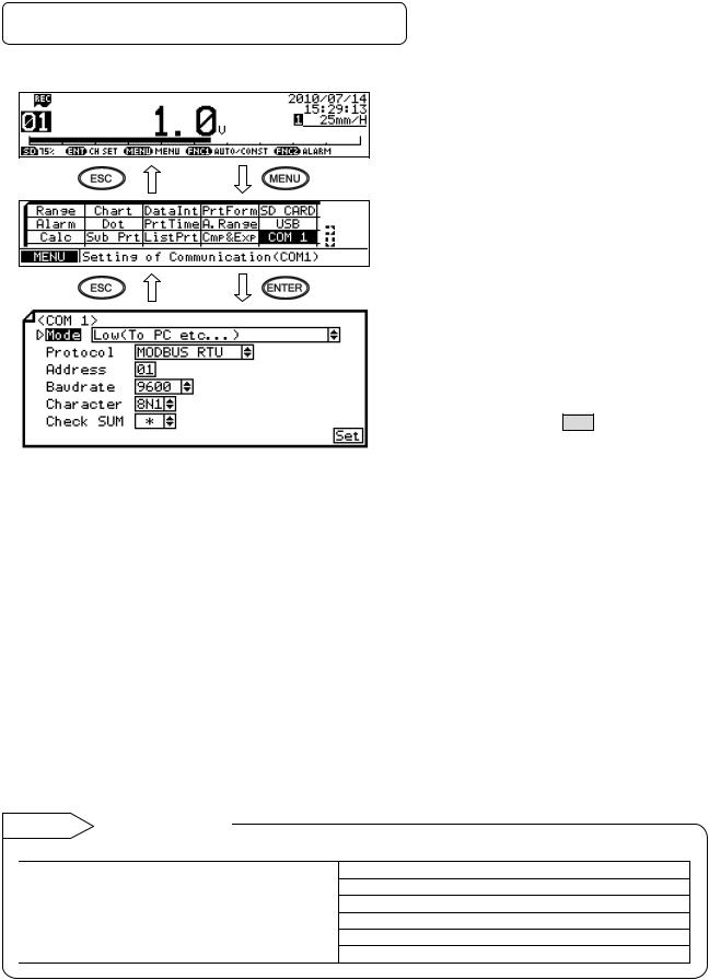
6-2. COM Settings (For AL4000/AH4000)
Set each parameter.
Note: Actual windows are separated. Use the ▲/▼ keys to scroll and continue settings.
[List of COM1 and COM2 setting parameters]
(1)Pressing the  key displays the menu window (list of setting items).
(2)Select “COM1” or “COM2”.
(3)Move the cursor to the parameter to be set with the ▲/▼/ / keys.
(4)Press the  key to make it available for setting and then select or enter a value.
(5)After completing the settings of this item,
move the cursor to Set .
(6)Press the  key to register the
settings (when chart recording is ON, a setting change mark is printed). To cancel the settings, press the  key.
key.
Parameter |
Function |
Default |
Set value |
Mode |
Communication mode |
Low(To PC etc…) |
Fixed to Low (To PC etc…) |
Protocol |
Select communication |
MODBUS RTU |
MODBUS RTU, MODBUS ASCII, PRIVATE1 (without |
|
protocol |
|
connection sequence), PRIVATE2 (with connection |
|
|
|
sequence) |
Address |
Set communication |
01 |
01 to 99 |
|
address of the unit |
|
|
Baudrate |
Set communication speed |
9600 |
PRIVATE: 1200, 2400, 4800, 9600bps |
|
|
|
MODBUS: 9600, 19200, 38400bps |
|
|
|
Changes to “9600” when changing from PRIVATE to |
|
|
|
MODBUS or vice versa. |
Character |
Set transmission character |
8N1 |
7E1, 7E2, 7O1, 7O2, 8N1, 8N2, 8E1, 8E2, 8O1, 8O2 |
Check SUM |
Select whether to add |
* |
OFF, ON |
|
checksum code |
|
Settable only when Protocol is set to “PRIVATE”. |
Reference Character selection
Codes are used to represent characters. MODBUS RTU mode can set only 8-bit characters (see section 8-1).
Code |
Character length |
|
Parity |
Stop bit |
|
7E1 |
7-bit |
|
Even |
1 |
|
7E2 |
7-bit |
|
Even |
2 |
|
7O1 |
7-bit |
|
Odd |
1 |
|
7O2 |
7-bit |
|
Odd |
2 |
|
8N1 |
8-bit |
|
Non |
1 |
|
Code |
Character length |
Parity |
Stop bit |
8N2 |
8-bit |
Non |
2 |
8E1 |
8-bit |
Even |
1 |
8E2 |
8-bit |
Even |
2 |
8O1 |
8-bit |
Odd |
1 |
8O2 |
8-bit |
Odd |
2 |
*When connecting via Ethernet, communication protocol and communication address are fixed to “MODBUS RTU” and “01” respectively.
*Use the unit and PC at the same communication speed (use the default speed 9600bps in normal case).
*For RS422A/485, a communication address of the unit needs to be set. Make sure that one or more units connected to a PC have unique communication address and no overlap occurs.
For RS232C, only one unit is connected, but communication address needs to be set (use the default address 01 in normal case).
-9 -

6-3. COM Settings (For KL4000/KH4000)
Communication settings are performed with [ENG2 mode] which can be entered from a [ENG1 mode] item.
The [ENG2 mode] provides items for checking remote contact specifications and setting communication parameters.
Set communication parameters according to the flow chart.
1. Checking/setting items of communication specifications
|
2 sec or more |
|
or no key operation for 1 |
[Display mode] |
min or more |
+ |
2 sec or more |
Note Substitution key
Switching between [Display mode] and [ENG1 mode] can be done by the  key instead of the
key.
Option |
|
|
|
|
Start setting |
|
Communication |
Go to 2. Communications |
|
specifications |
|
|
protocol |
|
|
|
|
|
|
Go to 3. Transmission |
|
|
speed |
Enter [ENG2 mode] |
|
Go to 4. Communication |
|
|
|
|
|
address |
|
|
Go to 5. Communication |
|
|
character |
- 10 -
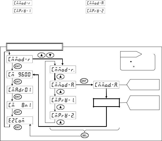
2. |
Setting communications protocol |
|
1) |
Setting range |
|
|
(MODBUS RTU mode) |
(MODBUS ASCII mode) |
|
(PRIVATE1: No communication address) |
(PRIVATE2: Communication address available) |
2)Setting flow chart
<Example> Mode is changed from MODBUS RTU to MODBUS ASCII.
*Communications protocol is selected by the  key in this example, but you can also use the
  key to reverse.
Communication specification items
|
Reference |
Decimal |
Start setting |
point |
|
|
|
|
|
ON: |
|
|
Flash: |
|
(4) |
(5) |
|
Decimal points of all digits flash
 (6)
(6)
Save in the memory Register and print setting
change mark
3)Setting procedure
(1)Enter [ENG1 mode]
Press and hold the  and
and  keys for two seconds or more to change from [Display mode] to [ENG1 mode].
(2)Enter [ENG2 mode]
Pressing the  key changes ENG1 item. Select
  . Press the
  key to enter [ENG2 mode].
(3)Select communication specification
Pressing the  key changes ENG2 item. Select
  and press the
  key.
key.
(4)Start communications protocol setting
Pressing the  /
/  key displays the cursor (flashing decimal point). Select
  .
.
(5)Check selection
Pressing the  key flashes decimal points of all digits. If an error is found, press the
  /
/  key to reset.
(6)Register setting
When set correctly, press the  key. The setting is saved in the memory and setting change mark is printed.
(7)End
The setting window of transmission speed will be displayed. Also, the mode returns to [Display mode]
when the  key is pressed and held for two seconds or more on any setting display window, or keys are not operated for one minute or more.
-11 -
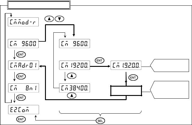
3.Setting transmission speed
1)Setting range
MODBUS: 9600, 19200, 38400bps PRIVATE: 1200, 2400, 4800, 9600bps
2)Setting flow chart
<Example> Transmission speed of MODBUS protocol is changed from 9600 to 19200bps.
*Transmission speed is selected by the  key in this example, but you can also use the
  key to reverse.
Communication specification items
Start setting
 (4)
(4)

 (5)
(5)
(6)
Decimal points of all digits flash
(7)
Save in the memory Register and print setting
change mark
3)Setting procedure
(1)Enter [ENG1 mode]
Press and hold the  and
and  keys for two seconds or more to change from [Display mode] to [ENG1 mode].
(2)Enter [ENG2 mode]
Pressing the  key changes ENG1 item. Select
  . Press the
  key to enter [ENG2 mode].
(3)Select communication specification
Pressing the  key changes ENG2 item. Select
  and press the
  key.
key.
(4)Select transmission speed
Pressing the  key changes communication specification item. Select
  (previous set value is displayed).
(5)Start setting
Pressing the  /
/  key displays the cursor (flashing decimal point). Select
  .
.
(6)Check selection
Pressing the  key flashes decimal points of all digits. If an error is found, press the
  /
/  key to reset.
(7)Register setting
When set correctly, press the  key. The setting is saved in the memory and setting change mark is printed.
(8)End
The setting window of communication address will be displayed. Also, the mode returns to [Display mode]
when the  key is pressed and held for two seconds or more on any setting display window, or keys are not operated for one minute or more.
-12 -
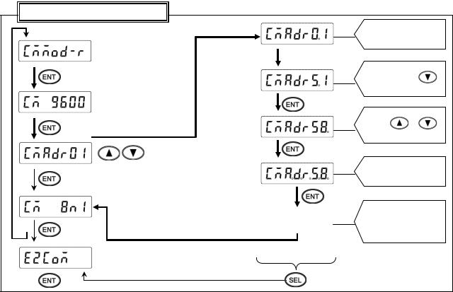
4.Setting communication address
1)Setting range: 01 to 99
*For RS422A/485, a communication address of the unit needs to be set. Make sure that one or more units connected to a PC have unique communication address and no overlap occurs. For RS232C, only one unit is connected, but communication address needs to be set (use the default address 01 in normal case).
2) Setting flow chart <Example> Communication address is changed from 01 to 58.
Communication specification items
Cursor appears on the tens place
Press  /
/
|
(5) |
|
|
|
||
(4) |
|
|
|
|
Press |
/ |
|
|
|
|
|
|
|
Start setting |
(6) |
|
|
|
||
|
|
|
|
|||
|
|
|
|
|
Decimal points of all |
|
|
|
|
|
|
digits flash |
|
|
|
|
|
(7) |
|
|
|
|
|
|
|
Save in the memory |
|
|
Register |
|
and print setting |
|||
|
|
|
|
|
change mark |
|
|
|
|
|
|
|
|
|
|
|
|
|
|
|
3)Setting procedure
(1)Enter [ENG1 mode]
Press and hold the  and
and  keys for two seconds or more to change from [Display mode] to [ENG1 mode].
(2)Enter [ENG2 mode]
Pressing the  key changes ENG1 item. Select
  . Press the
  key to enter [ENG2 mode].
(3)Select communication specification
Pressing the  key changes ENG2 item. Select
  and press the
  key.
key.
(4)Select communication address
Pressing the  key changes communication specification item. Select
  (previous set value is displayed).
(5)Start setting
Pressing the  /
/  key displays the cursor (flashing decimal point) on the tens place. Pressing the
  /
/  key increases/decreases numeric value. Press the
  key to move the cursor right, and set the ones place likewise.
(6)Check set value
Pressing the  key flashes decimal points of all digits. If an error is found, press the
  /
/  key to reset.
(7)Register setting
When set correctly, press the  key. The setting is saved in the memory and setting change mark is printed.
(8)End
The setting window of communication character will be displayed. Also, the mode returns to [Display mode]
when the  key is pressed and held for two seconds or more on any setting display window, or keys are not operated for one minute or more.
-13 -
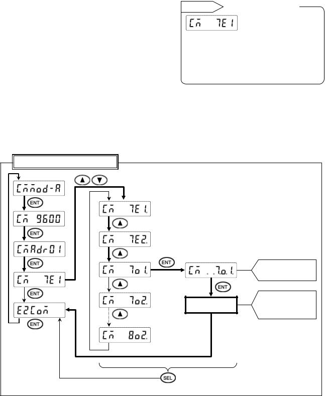
5.Setting communication character
1)Setting range
|
Display |
|
|
Character length |
|
|
Parity |
|
|
Stop bit |
|
|
|
|
|
|
|
|
|
|
|
|
|
|
|
|
|
|
|
Reference |
|
|
|
Display and meaning |
|
||||||||
|
7E1 |
|
|
7-bit |
|
|
Even |
|
1 |
|
|
|
|
|
|||||||
|
|
|
|
|
|
|
|
|
|
|
|
|
|
|
|
|
|||||
|
7E2 |
|
|
7-bit |
|
|
Even |
|
2 |
|
|
|
|
|
|
|
|
|
|
|
|
|
|
|
|
|
|
|
|
|
|
|
|
|
|
|
|
|
|||||
|
7O1 |
|
|
7-bit |
|
|
Odd |
|
1 |
|
|
|
|
|
|
|
|
|
|
|
|
|
|
|
|
|
|
|
|
|
|
|
|
|
|
|
|
|
|
|
|
|
|
|
7O2 |
|
|
7-bit |
|
|
Odd |
|
2 |
|
|
|
|
|
|
|
|
|
Stop bit |
||
|
|
|
|
|
|
|
|
|
|
|
|
|
|
|
|||||||
|
8N1 |
|
|
8-bit |
|
|
Non |
|
1 |
|
|
|
|
|
|
|
|
|
(1: 1 bit, 2: 2 bits) |
||
|
|
|
|
|
|
|
|
|
|
|
|
|
|
|
|||||||
|
8N2 |
|
|
8-bit |
|
|
Non |
|
2 |
|
|
|
|
|
|
|
|
|
|||
|
|
|
|
|
|
|
|
|
|
|
|
|
|
|
Parity |
||||||
|
8E1 |
|
|
8-bit |
|
|
Even |
|
1 |
|
|
|
|
|
|
|
|
|
|||
|
|
|
|
|
|
|
|
|
|
|
|
|
|
|
(E: EVEN, O: ODD, N: NON) |
||||||
|
8E2 |
|
|
8-bit |
|
|
Even |
|
2 |
|
|
|
|
|
|
|
|
|
|||
|
|
|
|
|
|
|
|
|
|
|
|
|
|
|
Character length |
||||||
|
8O1 |
|
|
8-bit |
|
|
Odd |
|
1 |
|
|
|
|
|
|
|
|
|
|||
|
|
|
|
|
|
|
|
|
|
|
|
|
|
|
(7: 7-bit, 8: 8-bit) |
||||||
|
8O2 |
|
|
8-bit |
|
|
Odd |
|
2 |
|
|
|
|
|
|
|
|
|
|||
|
|
|
|
|
|
|
|
|
|
|
|
|
|
|
|
|
|||||
*MODBUS RTU mode can set only 8-bit characters (see section 8-1).
2)Setting flow chart
<Example> Communication character is changed from 7E1 to 7O1.
*Communication character is selected by the  key in this example, but you can also use the
  key to reverse.
Communication specification items
Start setting
(5) |
(6) |
|
|
||
(4) |
|
|
|
|
|
|
|
|
Decimal points of all digits flash
(7)
Save in the memory Register and print setting
change mark
- 14 -
3)Setting procedure
(1)Enter [ENG1 mode]
Press and hold the  and
and  keys for two seconds or more to change from [Display mode] to [ENG1 mode].
(2)Enter [ENG2 mode]
Pressing the  key changes ENG1 item. Select
  . Press the
  key to enter [ENG2 mode].
(3)Select communication specification
Pressing the  key changes ENG2 item. Select
  and press the
  key.
key.
(4)Select communication character
Pressing the  key changes communication specification item. Select
  (previous set value is displayed).
(5)Start setting
Pressing the  /
/  key displays the cursor (flashing decimal point). Select
  .
.
(6)Check selection
Pressing the  key flashes decimal points of all digits. If an error is found, press the
  /
/  key to reset.
(7)Register setting
When set correctly, press the  key. The setting is saved in the memory and setting change mark is printed.
(8)End
The selection window of communication specification will be displayed. Also, the mode returns to [Display
mode] when the  key is pressed and held for two seconds or more on any setting display window, or keys are not operated for one minute or more.
- 15 -
7. Wiring
7-1. Precautions on Wiring
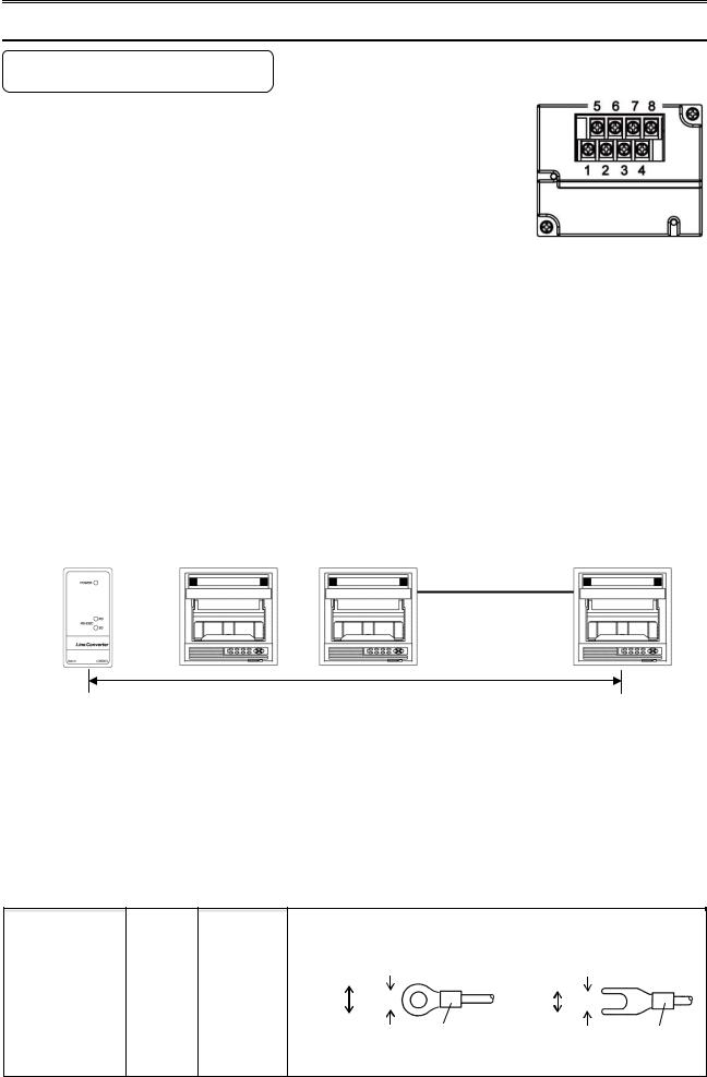
1. Communication terminal
Terminal layout depends on the selection of communication interface.
|
|
1 |
2 |
3 |
4 |
5 |
6 |
7 |
8 |
|
|
|
|
|
|
|
|
|
|
|
RS232C |
|
|
|
SG |
SD |
|
RD |
|
|
|
|
|
|
|
|
|
|
|
COM1 |
RS422A |
|
|
|
SG |
SDA |
SDB |
RDA |
RDB |
|
|
|
|
|
|
|
|
|
|
RS485 |
|
|
|
SG |
SA |
SB |
Short |
Short |
|
|
|
|
|
||||||
|
|
|
|
with SA |
with SB |
||||
|
|
|
|
|
|
|
|
||
COM2 |
RS485 |
SA |
SB |
SG |
|
|
|
|
|
|
|
|
|
|
|
|
|
|
|
*RS232C and RS422A/485 of COM1 are specified on purchase.
*COM2 is supported by AL4000/AH4000 only.
2.RS422A/485 communication cable extended up to 1.2km
The interval between instruments can be decided freely, however, note that the total cable length should be 1.2km or less.
Line converter |
Unit |
|
|
|
|
Total cable length: 1.2km or less
3. Take measure against noise
To avoid interference from noise, keep the communication cable separated from the power or other communication cables, with a gap of at least 50cm between them.
4. Make sure to use crimping terminals
One of the causes of communication failure is a disconnection of cables. Make sure to install an O type or Y type crimping terminal with insulation sleeve to the end of communication cable.
|
|
Terminal board |
|
|
Diameter |
|
|
Tightening |
|
|
|
|
|
Termination treatment (unit: mm) |
|
|||||||
|
|
|
|
|
|
|
|
|
|
|
|
|||||||||||
|
|
|
|
|
|
|
|
|
|
|
||||||||||||
|
|
|
|
|
|
torque |
|
|
|
|
|
|
||||||||||
|
|
|
|
|
|
|
|
|
|
|
|
|
|
|
|
|
|
|
|
|
|
|
|
|
|
|
|
|
|
|
|
|
|
|
|
|
|
|
|
|
|
|
|
||
|
|
|
|
|
|
|
|
|
|
O type |
|
|
t: 0.8 |
Y type |
|
t: 0.8 |
||||||
|
|
|
|
|
|
|
|
|
|
|
|
|
|
|
|
|
||||||
|
|
Communications |
|
|
|
|
|
|
|
|
|
|
|
|
|
|
|
|
|
|
||
|
|
|
|
|
|
|
|
5.2 or less |
|
|
|
|
|
5.2 or less |
|
|
|
|
||||
|
|
|
|
|
|
|
|
|
|
|
|
|
|
|
|
|
||||||
|
|
|
|
|
|
|
|
|
|
|
|
|
|
|
|
|
||||||
|
|
|
M3 |
|
0.5 N∙m |
|
3.2 or more |
|
|
|
3.2 or more |
|||||||||||
|
|
|
|
|
|
|
|
|
|
|
|
|
|
|||||||||
|
|
terminal |
|
|
|
|
|
|
|
|
|
|
|
|
|
|
|
|
||||
|
|
|
|
|
|
|
|
|
|
|
|
|
|
|
|
|
|
|||||
|
|
|
|
|
|
|
|
|
|
|
With an insulation sleeve |
With an insulation sleeve |
||||||||||
|
|
|
|
|
|
|
|
|
|
|
|
|
||||||||||
* O type is preferred.
- 16 -
5. Add termination resistor
For RS422A/485 communications, install a 100Ω resistor to the unit which is located at the last edge of the communication line.
(See section 7-3.2 and 7-3.3.)
6. Number of connectable units
RS232C: One unit
RS422A/485: Up to 31 units
The number of connectable units specified above is based on the use of communication
! Caution IC conforming to the communication standards. However, the number of units or distance ensuring high quality communication varies depending on the type of
communication cable and other connected devices.
7-2. Communication Cable
Prepare a communication cable before wiring. Dedicated cables are available from us. Contact us when you need it.
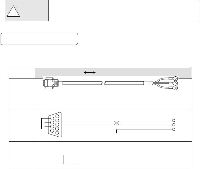
1. RS232C
Connection between PC and the unit or a line converter
|
|
Cable |
|
|
9-pin connector |
Crimp type ring terminals RS232C cable |
|
|
|
|
|
|
|||
|
|
|
|
|
|
|
RD |
|
|
|
|
|
|
|
|
|
|
|
|
|
|
|
SD |
|
|
|
|
|
Cable for RS232C (Max. 15m) |
SG |
|
|
|
Shape |
|
PC side |
|
|
|
|
|
|
9-pin connector |
|
|
||
|
|
|
|
|
|
|
|
|
1 |
|
|
6 |
RD |
Internal |
2 |
|
7 |
SD |
|
|
3 |
|
wiring |
8 |
|
4 |
SG |
|
|
9 |
|
|
5 |
|
Model |
RZ - CR S6 □□ |
|
code |
|
|
Cable length: 01 to 15m (specified)
- 17 -
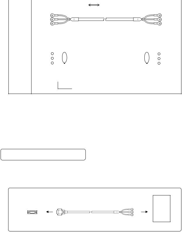
2. |
RS422A |
|
|
|
|||
|
|
Connection between a line converter and the unit |
|
|
|||
|
|
|
|
|
|
|
|
|
|
|
Cable |
|
Crimp type ring terminals |
Crimp type ring terminals RS422A cable |
|
|
|
|
|
|
|||
|
|
|
|
|
|
|
|
|
|
|
|
|
|
(for a line converter) |
|
|
|
|
Shape |
|
|
|
|
|
|
|
|
|
RDA (black) |
(black) |
SDA |
|
|
|
|
|
RDB (white) |
(white) |
SDB |
|
|
|
|
|
SDA (red) |
(red) |
RDA |
|
|
|
|
|
SDB (green) |
(green) RDB |
|
|
|
|
|
|
SG (blue) |
(blue) |
SG |
|
|
|
|
|
Line converter side |
Recorder side |
|
4-core cable of twisted 2-core cables of twisted VCTF lines. Each side has a SG (single ground) line. Since the line converter has no SG terminal, cut and use the cable.
|
RDA |
SDA |
|
Internal |
RDB |
SDB |
|
SDA |
RDA |
|
|
wiring |
|
||
SDB |
RDB |
|
|
|
|
||
|
SG |
SG |
|
Model |
RZ - CR A2 □□ |
|
|
code |
|
|
|
|
Cable length: 01 to 99m (specified) |
|
|
Connection between the unit and other devices |
|
|
|
Cable |
Crimp type ring terminals |
Crimp type ring terminals RS422A cable |
|
|
|
|
|
|
|
(for parallel) |
|
Shape |
|
|
|
SDA (black) |
(black) |
SDA |
|
SDB (white) |
(white) |
SDB |
|
RDA (red) |
(red) |
RDA |
|
RDB (green) |
(green) RDB |
||
SG |
(blue) |
(blue) |
SG |
|
Device side |
Recorder side |
|
4-core cable of twisted 2-core cables of twisted VCTF lines. Each side has a SG |
|
||
(single ground) line. |
|
|
|
|
SDA |
SDA |
|
Internal |
SDB |
SDB |
|
RDA |
RDA |
|
|
wiring |
|
||
RDB |
RDB |
|
|
|
|
||
|
SG |
SG |
|
Model |
RZ - CR A1 □□ |
|
|
code |
|
|
|
Cable length: 01 to 99m (specified)
- 18 -
3. |
RS485 |
|
|
|
|
|
|
|
|
|||
Connection between the unit and other devices and between a line converter and the unit |
|
|||||||||||
|
|
|
|
|
|
|
|
|
|
|
|
|
|
|
|
Cable |
|
|
Crimp type ring terminals |
Crimp type ring terminals RS485 cable |
|
||||
|
|
|
|
|
|
|||||||
|
|
|
|
|
|
|
|
|
|
|
|
|
|
|
|
|
|
RDA (black) |
|
(black) SA |
|
||||
|
|
|
|
|
RDB (white) |
|
(white) SB |
|
||||
|
|
|
|
|
SG (green) |
|
(green) SG |
|
||||
|
|
|
Shape |
|
Device/line converter side |
Recorder side |
|
|||||
|
|
|
|
|
|
2-core cable of twisted CVVS lines. Each side has a SG (single ground) line. Since |
|
|||||
|
|
|
|
|
|
the line converter has no SG terminal, cut and use the cable. |
|
|||||
|
|
|
|
|
|
|
|
|
|
|
|
|
|
|
|
Internal |
|
RDA |
|
|
SA |
|
|||
|
|
|
|
|
|
|
||||||
|
|
|
|
RDB |
|
|
|
SB |
|
|||
|
|
|
wiring |
|
|
|
|
|||||
|
|
|
|
SG |
|
|
|
SG |
|
|||
|
|
|
|
|
|
|
|
|
||||
|
|
|
|
|
|
|
|
|
|
|||
|
|
|
Model |
|
RZ - LEC □□□ |
|
|
|
||||
|
|
|
code |
|
|
|
|
|
|
|
|
|
Cable length: 001 to 200m (specified)
4.Ethernet (AL4000/AH4000 only)
●Connection between PC and device
When connecting a device to a PC directly (one-to-one), use a shielded, crossover twisted pair cable (commercially available STP cable).
●Connection between HUB and device (multiple devices can be connected)
When connecting devices to a PC via HUB (one-to-N), use a shielded, straight twisted pair cable (commercially available STP cable).
7-3. Communication Line Wiring
1. RS232C wiring
PC and device are connected one-to-one in RS232C communication.
Example of terminal connection
Communications port |
RZ-CRS6 |
|
RD |
|
SD |
|
SG |
PC side |
Cable for RS232C (Max.15m) |
 RD
RD
 SD
SD
 SG
SG
Device side
- 19 -
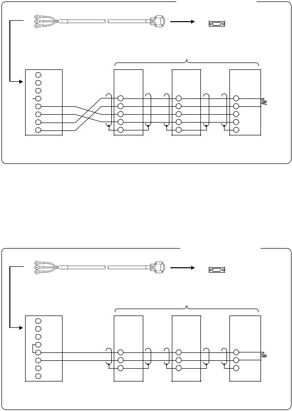
2. RS422A wiring
PC and multiple devices are connected in RS422A communication. A line converter is required. RS422A cable is within 1.2km of total extension and up to 31 devices can be connected. Install a resistor of 100Ω to the last edge of the transmission line device side.
(General metal film resistors will be fine. They are available from us, so contact us when you need it.)
Example of terminal connection
RZ-CRS6 |
Communications port |
RD |
|
SD |
|
SG |
|
Cable for RS232C (Max. 15m) |
PC side |
|
Line converter
SC8-10
1RD
2SD
3SG
 45 RDA 6 RDB
7 SDA
8 SDB
Turn the switch of RS422A/RS485 to RS422A.
Device side
RDA |
RDA |
RDA |
|
RDB |
RDB |
RDB |
|
SDA |
SDA |
SDA |
|
SDB |
SDB |
||
SDB |
|||
SG |
SG |
||
SG |
|||
|
|
Avoid connecting SG line to FG terminal or ground terminal of the device.
Termination
resistor
100Ω
100Ω
3. RS485 wiring
PC and multiple devices are connected in RS485 communication. A line converter is required. RS485 cable is within 1.2km of total extension and up to 31 devices can be connected.
Install a resistor of 100Ω to the last edge of the transmission line device side.
(General metal film resistors will be fine. They are available from us, so contact us when you need it.)
Example of terminal connection
RZ-CRS6
RD
SD
SG
Cable for RS232C (Max. 15m)
Line converter
SC8-10
1RD
2SD
3SG
54 |
RDA |
SA |
6 |
RDB |
SB |
7 |
|
SG |
|
|
|
8 |
|
|
Communications port
PC side
Device side
SA |
SA |
SB |
SB |
SG |
SG |
|
Turn the switch of RS422A/RS485 |
Avoid connecting SG line to FG terminal or |
to RS485. |
ground terminal of the device. |
Termination
resistor
100ΩΩ
- 20 -
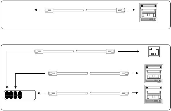
4.Ethernet wiring (AL4000/AH4000 only)
●Example of connection between PC and Ethernet device (one-to-one connection)
|
|
|
|
|
|
Shielded, crossover twisted pair cable |
|
|
|
|
|
|
|
||
|
|
|
|
|
|
||
|
|
|
|
|
|
||
|
|
|
|
|
|
||
PC side |
|||||||
(Max. 100m) |
|||||||
|
|
|
|
|
|
||
|
|
|
|
|
|
Device side |
|
● Example of connection between PC, HUB and Ethernet device (one-to-N connection)
Shielded, straight twisted pair cable |
|
(Max. 100m) |
PC side |
Shielded, straight twisted pair cable (Max. 100m)
|
|
Shielded, straight twisted pair cable |
HUB |
|
(Max. 100m) |
Device side
- 21 -

8. MODBUS Protocol
! |
Caution |
Make sure to read and understand this section to avoid any troubles. |
|
|
|
|
|
|
1. Requesting data immediately after power-on generates an error
The unit is always ready for communications and responsive to data request from PC. However, after power-on, the unit does not respond normally until channel data becomes ready.
For example, it takes about 20 seconds for a 24-point AH4000 recorder to have the data ready. When a data request is received during this period, the unit returns an error.
2. Keys restricted in parameter setting (writing)
When operating the unit from PC to set parameters, etc., the  /
/  key becomes temporarily unavailable while a setting window is displayed. The key will be available again by changing the window displayed.
3. RS232C requires communication address
Although PC and the unit are connected one-to-one in RS232C communication, a communication address needs to be set to establish communication.
4. Be careful about command re-transmission as no control signal line is used
The serial interface of the unit makes communication without using a control line. Therefore, attention should be paid when re-transmitting a command since reception failure may occur depending on the unit condition.
5.Do not disconnect communication cable or device, or turn ON/OFF the power during communication
Disconnecting the cables or devices constituting the serial interface, or turning ON/OFF the devices during communication may stop operation or generate an error. If this happens, all the devices constituting the serial interface need to be reset to start the operation from the beginning.
6.Make sure that communication driver has been turned OFF before sending next command
For RS422A/485 communication, multiple devices are connected in the same communication line, but only one device whose communication address is specified by PC passes through the communication line. To send all characters safely to PC, the communication line driver is turned OFF a few moments (about 5ms) after sending the last character. If a PC sends a command to the next device before the driver is turned OFF, signals will interfere with each other resulting in communication failure.
- 22 -
8-1. Message Transmission Mode
Two types of message transmission mode are available: RTU (Remote Terminal Unit) mode and ASCII mode, which can be selected using the front keys.
Comparison between RTU and ASCII modes
Item |
RTU mode |
|
ASCII mode |
||
Interface |
|
RS232C, RS422A, RS485 |
|||
Communication system |
Half-duplex start-stop synchronization |
||||
Transmission speed |
|
9600, 19200, 38400bps |
|||
Transmission code |
|
Binary |
|
ASCII |
|
|
|
|
|
|
|
Error check |
|
Vertical |
|
Parity |
|
(Error detection) |
|
Horizontal |
CRC-16 |
|
LRC |
|
|
|
|
|
|
Character |
|
Start bit |
|
1 bit |
|
configuration |
|
|
|
|
|
|
Data length |
8 bits |
|
7 bits, 8 bits |
|
|
|
Parity bit |
None, odd, even |
|
None*, odd, even |
|
|
|
|
|
|
|
|
Stop bit |
|
1bit/2 bits |
|
Message start code |
|
None |
|
: (Colon) |
|
|
|
|
|
|
|
Message end code |
|
None |
|
CR, LF |
|
Data time interval |
|
28-bit time or less |
|
1 second or less |
|
|
|
|
|
|
|
*For the case of 7-bit data, parity bit cannot be “None”.
1.Transmission data
The RTU mode transmits binary data. The ASCII mode divides the 8-bit binary data of RTU into high-order four bits and low-order four bits, and turns them into characters (0 to 9, A to F).
Example: RTU mode |
ASCII mode |
||
|
|
|
|
|
67H |
|
36H (“6”) |
|
|
|
|
|
89H |
|
37H (“7”) |
|
|
|
|
|
ABH |
|
38H (“8”) |
|
|
|
|
|
|
|
39H (“9”) |
|
|
|
|
|
|
|
41H (“A”) |
|
|
|
|
|
|
|
42H (“B”) |
|
|
|
|
The RTU mode enables more efficient transmission since its message is half in length compared to the ASCII mode.
2. Message frame structure
With RTU mode, the message frame consists of message section only.
With ASCII mode, the message frame consists of start character “: (colon, 3AH)”, message and end characters “CR (carriage return, 0DH) + LF (line feed, 0AH)”.
RTU mode |
|
|
ASCII mode |
|
|
|
|
|
|
|
|
Message |
|
: |
Message |
CR |
LF |
|
|
|
|
|
|
The ASCII mode makes troubleshooting easier since it uses a message start character “:”.
- 23 -

8-2. Data Time Interval
RTU mode: 28-bit time or less (9600bps: 2.8msec, 19200bps: 1.4msec, 38400bps: 0.7msec) ASCII mode: One second or less
When sending a message, keep the time interval between data constituting one message no longer than the time specified above. If it is longer than the time specified above, the receiver side (the unit) recognizes that transmission of data from the sender side is complete, and the data is handled as an abnormal message.
While the RTU mode requires continuous transmission of message characters, the ASCII mode allows for a maximum interval of one second between characters, making it possible to use a master (PC) with a relatively slow processing speed.
8-3. Message Structure
MODBUS message has the following structure which is applied to both RTU and ASCII modes.
Slave address
Function code
Data
Error check
1. Slave address
A slave address can be set in advance using the front keys within the range of 1 to 99. Normally, master device communicates with a single slave device. Only a slave device whose address matches the slave address in a command message from the master device sends a response.
The slave address “0” is used for a message addressed to all slave devices (broadcast) from the master device. In this case, the slave devices do not send a response.
2. Function code
Function codes represent the functions to be executed by slave devices. The data is generally classified as shown in the table below. The table also shows the comparison between MODBUS original functions and MODBUS-compatible CHINO device functions (see section 8-9).
Function code table
Code |
Function |
Unit |
MODBUS original function |
|
|
|
(reference) |
01 |
Read digital (ON/OFF) settings |
1 bit |
Read coil status |
02 |
Read digital input data |
1 bit |
Read input relay status |
03 |
Read analog settings |
16 bits |
Read holding register contents |
04 |
Read analog input data |
16 bits |
Read input register contents |
05 |
Write digital setting |
1 bit |
Change single coil status |
06 |
Write analog setting |
16 bits |
Write to single holding register |
08 |
Send received data (for diagnosis) |
|
Loop-back test |
16 |
Write multiple analog settings |
|
Write to multiple holding registers |
70 |
Read floating data |
|
Arbitrary command of vendors |
71 |
Write floating data |
|
Arbitrary command of vendors |
- 24 -

(1) |
Digital settings: |
Parameters mainly used to change functions such as recording ON/OFF and data printing |
|
|
execution. |
(2) |
Digital input data: |
Event status, etc. |
(3) |
Analog settings: |
Information of various settings |
|
|
Within the range of 16-bit numeric values (-32768 to 32767) |
(4) |
Analog input data: |
Measured data, unit specifications, etc. |
|
|
Outputs a numeric value within the 16-bit range |
(5) |
Floating data: |
When the data cannot be expressed by a numeric value within the 16-bit range (-32768 to |
|
|
32767), floating data is used. |
3. Data field
Data components depend on the function code. A master request consists of the code number of read/write target data (a relative number obtained from reference number described in the following section) and the number of data pieces. A slave response consists of the data responding to request.
Basic MODBUS data consists of 16-bit integers only, and the use of sign is specified for each data piece. Therefore, real number data such as measured data is expressed by assigning the decimal point position to a separate address to express an integer value, or by fixing the decimal point position and normalizing with the scale upper and lower limits.
This unit employs the system of assigning the decimal point position to a separate address.
The numeric data which cannot be expressed by 16-bit integers can be read or written using floating data.
The data field may contain the data like input data which assigns a specific numeric
! Caution value as error data. When handling such data, perform error judgment on the data before combining with decimal point data.
When decimal point data is combined first, error data is recognized as normal data.
4. Reference number.
All the data handled by the unit has “reference number” assigned, and this number is required when reading/writing data.
The data is classified into “Digital settings”, “Digital input data”, “Analog input data”, “Analog settings” and “Floating data (floating point data)” by its type.
A “relative number” corresponding to the reference number is specified in a message.
Reference numbers and corresponding relative numbers
Data type |
|
|
Reference No. |
|
Relative No. |
MODBUS original function |
|
|
|
|
|
|
(reference) |
Digital settings |
|
|
1 to 10000 |
|
Reference No. - 1 |
Coil |
Digital input data |
|
|
10001 to 20000 |
|
Reference No. - 10001 |
Input relay |
Analog input data |
|
|
30001 to 40000 |
|
Reference No. - 30001 |
Input register |
Analog settings |
|
|
40001 to 50000 |
|
Reference No. - 40001 |
Holding register |
Floating data |
|
|
50001 to 60000 |
|
Reference No. - 50001 |
|
(Floating point data) |
|
|
|
|
|
|
|
|
|
|
|
|
For example, a relative number of “Reference No. 30101 (CH1 data)” described later is “100”.
- 25 -
Quick search table for reference No.
|
Data type |
|
|
Parameter |
|
|
Reference No |
|
|
Applicable |
|
|
Reference table |
|
|
|
|
|
|
|
|
Function code |
|
|
|
||||
|
|
|
|
|
|
|
|
|
|
|
|
|
|
|
|
|
|
|
Key lock |
|
|
|
|
|
|
|
|
|
|
|
|
|
|
Message printing 1 |
|
|
|
|
|
|
|
|
|
|
|
|
|
|
Recording ON/OFF |
|
|
|
|
|
|
|
|
|
|
|
|
|
|
Feed |
|
|
|
|
|
|
|
|
|
|
Digital settings |
|
List printing |
|
01 to 95 |
|
01 (READ) |
|
|
See section 8-9.1 |
|||||
|
Title printing (message printing 2) |
|
|
05 (WRITE) |
|
|
||||||||
|
|
|
|
|
|
|
|
|
|
|
|
|||
|
|
|
|
Data printing |
|
|
|
|
|
|
|
|
|
|
|
|
|
|
Recording to SD card ON/OFF |
|
|
|
|
|
|
|
|
|
|
|
|
|
|
Fast dot printing |
|
|
|
|
|
|
|
|
|
|
|
|
|
|
SNTP time setting |
|
|
|
|
|
|
|
|
|
|
|
|
|
|
Remote contact status |
|
|
|
|
|
|
|
|
|
|
Digital input data |
|
Measured data status |
|
10009 to 10480 |
02 (READ) |
|
|
See section 8-9.2 |
||||||
|
|
|
|
Alarm status |
|
|
|
|
|
|
|
|
|
|
Analog input data |
|
Device information |
|
30001 to 30028 |
|
04 (READ) |
|
|
See section 8-9.3 |
|||||
|
Measured data |
|
30101 to 30148 |
|
|
|
||||||||
|
|
|
|
|
|
|
|
|
|
|
||||
|
|
|
|
Channel parameters |
|
40001 to 44394 |
|
|
|
|
|
|
||
|
|
|
|
Date and time setting |
|
|
|
|
|
|
|
|
|
|
|
|
|
|
Chart speed setting |
|
|
|
|
|
|
|
|
|
|
|
|
|
|
Dot printing interval setting |
|
|
|
|
|
|
|
|
|
|
|
|
|
|
Periodic data printing setting |
|
|
|
|
|
|
|
|
|
|
|
|
|
|
Recording format selection |
|
|
|
|
|
|
|
|
|
|
|
|
|
|
Zone printing setting |
|
|
|
|
|
|
|
|
|
|
|
|
|
|
Display setting |
|
|
|
|
|
|
|
|
|
|
|
|
|
|
Unit-tag switch setting |
|
|
|
|
|
|
|
|
|
|
|
|
|
|
Range setting |
|
|
|
|
|
|
|
|
|
|
|
|
|
|
Scale setting |
|
|
|
|
|
|
|
|
|
|
|
|
|
|
Burnout setting |
|
|
|
|
|
|
|
|
|
|
|
|
|
|
Sensor correction setting |
|
|
|
|
|
|
|
|
|
|
|
|
|
|
Recording color setting |
|
|
|
|
|
|
|
|
|
|
|
|
|
|
Subtract printing setting |
|
|
|
|
|
|
|
|
|
|
|
|
|
|
Unit setting |
|
|
|
|
|
|
|
|
|
|
|
|
|
|
Tag setting |
|
|
|
|
|
|
|
|
|
|
|
|
|
|
Alarm setting |
|
|
|
|
03 (READ) |
|
|
|
|
|
Analog settings |
|
Calculation setting |
|
|
|
|
06 (WRITE) |
|
|
See section 8-9.4 |
||||
|
|
|
|
Compressed/expanded printing setting |
|
|
|
|
16 (WRITE) |
|
|
|
|
|
|
|
|
|
Automatic range-shift setting |
|
|
|
|
|
|
|
|
|
|
|
|
|
|
Display and recording ON/OFF setting |
|
|
|
|
|
|
|
|
|
|
|
|
|
|
Communication setting |
|
45001 to 45487 |
|
|
|
|
|
|
||
|
|
|
|
Calendar timer setting |
|
46501 to 46574 |
|
|
|
|
|
|
||
|
|
|
|
Broken line approximation table setting |
|
47001 to 47412 |
|
|
|
|
|
|
||
|
|
|
|
SD card setting |
|
47906 to 47915 |
|
|
|
|
|
|
||
|
|
|
|
Measured value display order setting |
|
47931 to 47954 |
|
|
|
|
|
|
||
|
|
|
|
Title printing (message printing 2) |
|
48001 to 48038 |
|
|
|
|
|
|
||
|
|
|
|
Remote contact setting |
|
48069 to 48088 |
|
|
|
|
|
|
||
|
|
|
|
Operation recording setting |
|
48101 to 48181 |
|
|
|
|
|
|
||
|
|
|
|
Message printing 1 setting |
|
48202 to 48400 |
|
|
|
|
|
|
||
|
|
|
|
Periodic (specified time) data printing setting |
|
48501 to 48549 |
|
|
|
|
|
|
||
|
|
|
|
Formula setting |
|
48601 to 48900 |
|
|
|
|
|
|
||
|
|
|
|
Data communications input setting |
|
49001 to 49048 |
|
|
|
|
|
|
||
|
|
|
|
Fail out setting |
|
49101 to 49119 |
|
|
|
|
|
|
||
|
|
|
|
Communication parameter setting |
|
49902 to 49923 |
|
|
|
|
|
|
||
|
|
|
|
Measured data |
|
50101 to 50124 |
|
|
|
|
|
|
||
|
|
|
|
Data communications input |
|
50201 to 50224 |
|
|
|
|
|
|
||
|
|
|
|
Parameters set by each channel |
|
50301 to 51499 |
|
|
|
|
|
|
||
Floating data |
|
Range setting |
|
|
|
|
70 (READ) |
|
|
|
|
|||
|
Scale setting |
|
|
|
|
|
|
See section 8-9.5 |
||||||
(Floating point data) |
|
|
|
|
|
71 (WRITE) |
|
|
||||||
|
Alarm value |
|
|
|
|
|
|
|
|
|||||
|
|
|
|
|
|
|
|
|
|
|
|
|
||
|
|
|
|
Calculation setting |
|
|
|
|
|
|
|
|
|
|
|
|
|
|
Compressed/expanded printing setting |
|
|
|
|
|
|
|
|
|
|
|
|
|
|
Automatic range-shift setting |
|
|
|
|
|
|
|
|
|
|
- 26 -
5. Error check
The type of error check performed on transmission frame depends on the transmission mode.
RTU mode: CRC-16
ASCII mode: LRC
1)CRC-16 calculation
In CRC system, the data to be transmitted is divided by a generating polynomial and the resulting remainder is appended to the data. The generating polynomial is shown below.
1 + X2 + X15 + X16
Calculation is performed to the part from slave address to the end of data according to the following procedure.
(1)Initialize CRC-16 data (referred to as X) (= FFFFH)
(2)Exclusive logical sum (EX-OR) between data 1 and X → X
(3)Shift X one bit to the right → X
(4)When a carry is generated, perform EX-OR with A001H. If not, go to step (5) → X
(5)Repeat steps (3) and (4) until eight shifts have been performed.
(6)EX-OR between the next data and X → X
(7)Same as steps (3) to (5)
(8)Repeat until the last data.
(9)Create a message of the calculated 16-bit data (X). The low-order portion is followed by the high-order portion.
Example: For [02H] [07H] data, CRC-16 value becomes 1241H therefore the error check data will be [41H] [12H].
- 27 -
 Loading...