

Page 1
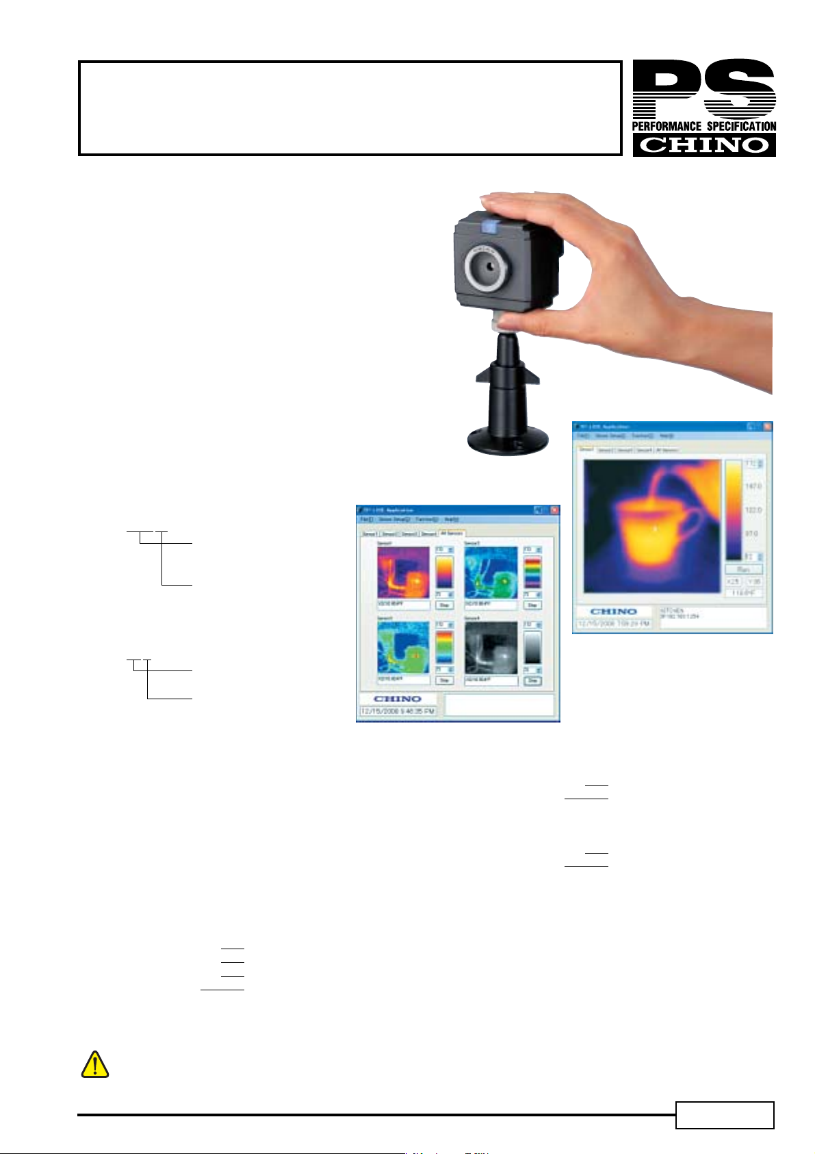
TP-L SERIES
Thermal Imaging Sensor
TP-L series is a compact infrared thermal
imaging sensor utilizing a thermopile array
detector.
This CHINO developed detector allows the
sensor to measure real time temperature.
Ethernet / USB connectivity allows the sensor
to communicate with PC running CHINO
Imaging Software.
■ FEATURES
●Easy to Use and Implement
●2000 pixel Resolution
●Built-In Alarms
●IP65 / NEMA4
■ MODEL
Low-temp type (−20 to 300℃)
TP-L02□□□N
Viewable Angle
25 : 25°x 25°
60 : 60°x 60°
Communications Interface
E : Ethernet
U : USB
High-temp type (100 to 800℃)
TP-L0225EK
Viewable Angle
25 : 25°x 25°
Communications Interface
E : Ethernet
■ SPECIFICATIONS
−
Temp Range: Low-temp type
Resolution: 0.5℃(Atblackbodytemperatureof100℃)
Accuracy: Low-temp type
±
±
Detector: Thermopile array Approx.2000 Pixel
Wavelength: Center wavelength 10μm
Viewable Angle: Low-temp type 60°x 60°,25°x 25°
Radius Resolution:
Frame Speed: Ethernet 3Hz (1Hz for alarm output)
Focus: Fixed focus
Emissivity: 0.10 to 1.00
*1 The inrush current should be considered for the selection of power source.
High-temp type 100 to 800℃
2% of reading or ±3℃whichever lager
High-temp type
1% of reading or ±3℃whichever lager
(At Ambient temp of 25℃
High-temp type 25°x 25°
60°x 60° 21.8mrad
25°x 25° 9.1mrad
USB 0.5Hz
20 to 300℃
±
2℃)
Communications Interface:
Ethernet 10BASE-T/100BASE-TX
USB USB2.0
Alarm: 2 points(Non voltage contact output)
Power Supply: 12 to 24V DC
Power Consumption:
Ethernet Max 2.5VA (At 12V DC)
Inrush Current
Working Temp:
Working RH: 10 to 80%RH (No dew condensation)
Casing: Polycarbonate (Color: Black)
Weight: Approx. 150g (sensor only)
Protection: IP65 (w/ provided exclusive cable and
Standards: CE (EN61326 Annex A)
1
USB Max 1VA (At 12V DC)
*1: Max 1.3A (At 12V DC)
−
10 to 50℃
tripod screw)
PSE-703A
Page 2
TP-L SERIES
■ FUNCTIONS
●Monitoring mode (with exclusive viewer software)
The temperature data is outputted continuously by a command from the PC.
●Capturing mode (without using exclusive viewer software)
The temperature data is outputted row-by-row horizontally by a command from PLC, etc.
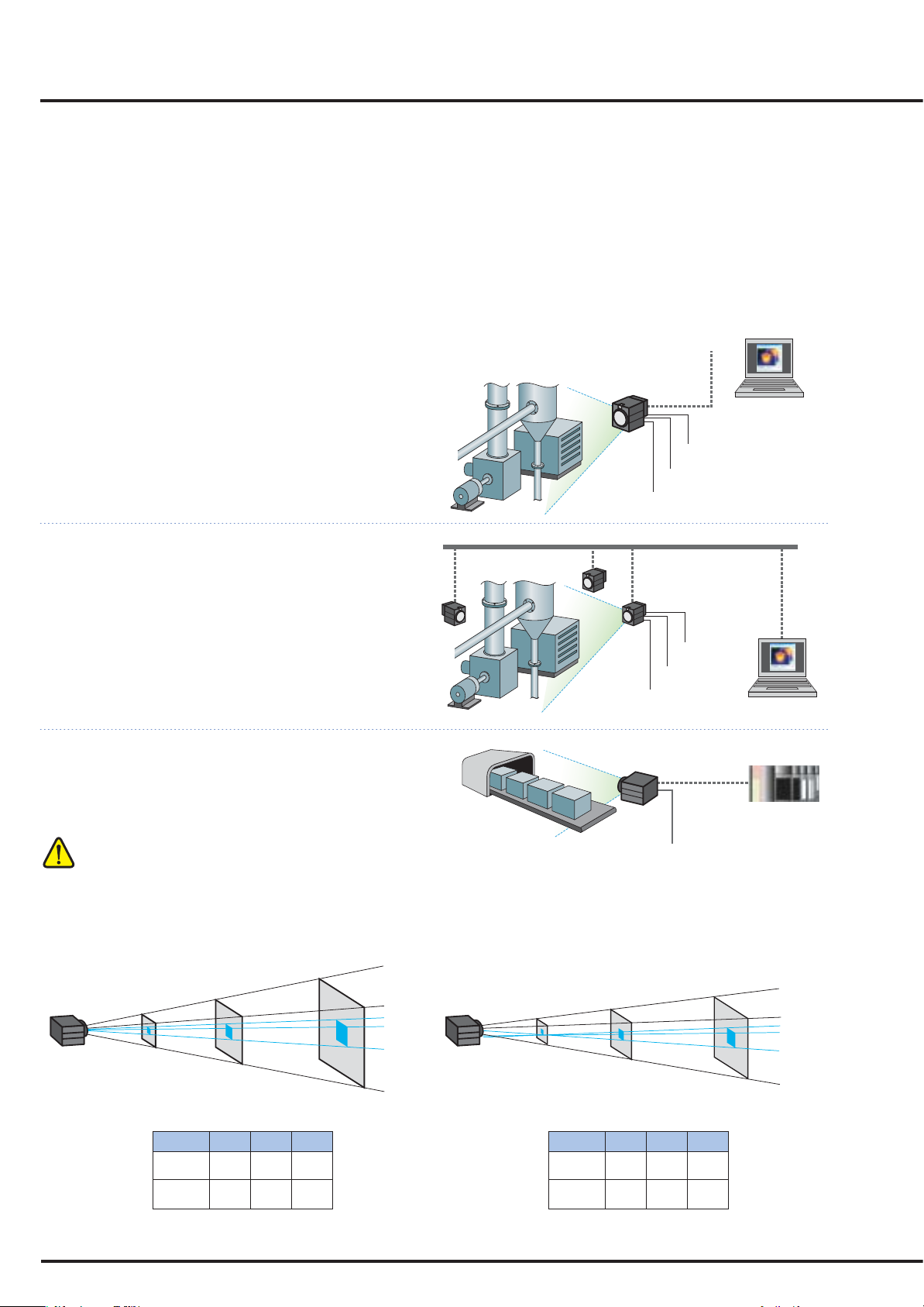
■ CONNECTIVITY
Viewer Software allows you monitor thermal images, measuring temperature and alarms.
Monitoring Mode
●Single unit usage
・Single unit can monitor 1 area and has 2 alarm
outputs.
・When alarm goes on, the unit stores 1 image to the
memory.
・Image saving updates every occurrence of alarm.
・Reading the data from host PC is possible.
●Multiple unit connection (LAN)
・Up to 4 sensors can be connected
・Monitoring and alarm outputs from sensor can be
used together.
Capturing Mode
●PLC connection
・The temperature data is outputted row-by-row
horizontally by a command from PLC, etc.
USB/LAN
ALARM
OUTPUT1
ALARM
OUTPUT2
POWER SUPPLY
(12-24 V DC)
ALARM
OUTPUT1
ALARM
OUTPUT2
POWER SUPPLY
(12-24 V DC)
LAN
LAN
PLC
When the capture mode is used, acquisition of command is required.
For the acquisition of command, contact your nearest distributor.
■ MEASURING SPOT SIZE AND DISTANCE
●Viewable Angle 60°x 60°
7.0m
1m
1.4
29
4.2m
3m
88mm
3m
4.2
88
□
View per pixel
146mm
5m
5m
7.0
146
1.4m
□
29mm
1m
D
Width
(m)
Width/Pix
(mm)
●Viewable Angle 25°x 25°
□
2
0.5m
□
10mm
1m
D
Width
(m)
Width/Pix
(mm)
1.5m
31mm
3m
1m
0.5
10
POWER SUPPLY
(12-24 V DC)
□
5m
3m
2.5
1.5
52
31
2.5m
52mm
5m
View per pixel
□
Page 3

■ APPLICATION SOFTWARE
●Requirements
OS : Windows 2000 (SP4 or later)/XP/Vista (Windows XP or later recommended)
* NET Framework 2.0 or later (required)
Memory : Windows 2000/XP.....1GB recommended (512MB or more)
: Windows Vista.....2GB or more recommended
CPU : Windows 2000/XP.....1.5GHz or faster recommended
: Windows Vista.....2GHz or faster recommended
* "Microsoft" and "Windows" are either trademarks or registered trademarks of Microsoft Corporation, USA.
* "Intel" and "Pentium" are either trademarks or registered trademarks of Intel Corporation, USA.
●Provided application software
Various functions of data storage, image processing, trend graph,
alarm settings, etc.
Via LAN up to 4 sensors can be connected to a PC.
Via USB 1 sensor can be connected to a PC.
●
Various settings of sensor
LAN settings / Alarm settings of the sensors / Emissivity setting
●
Data storage
Image temperature data storage (temperature data/csv for 2000 pixels) / Thermal image screen storage (JPEG)
●
Image processing
Screen averaging / Spatial smoothing / Median filter / Rotation / Maximum & Minimum values indications
●
Trend graph
By specifying a graph area, data can be displayed by the trend
graph and the graph data can be stored by setting. (Max. 8
areas)
●
Alarm settings by the application software
By specifying a graph area, alarms can be set. (Max. 8 areas)
Separately from the alarm settings of the sensor, the alarm
screening by the application software can be performed. (Max. 8
areas)
Trend graph Alarm screening
Alarm
●Multipoint connection software (OPTIONAL)
Email notification at the occurrence of alarm.
Via LAN up to 32 sensors can be connected to a PC.
*Ethernet application only
The alarm of the sensor is interlocked with the contact output, but the contact output cannot be activated with the alarm by the
application software.
3
Page 4

■ STANDARD CONFIGURATION
Orange
Bright
green
Pink
Blue
Screw size
1/4-20UNC
■ CONNECTION
●Example of contact output circuit
Use the contact output with a protection element for
preventing malfunction.
Thermal image sensor: 1 ea
Screw size
1/4-20UNC
Universal head: 1 ea
Connector cap: 1 ea
Screws
for the universal head: 3 ea
Carl plugs for mounting
the universal head
for concrete: 3 ea
Fixing screw: 1 ea
Fixed to the thermal image sensor
(w/ a crossing cable and an RJ-4 terminal) 2.5m: 1 ea
and the application software)
Exclusive LAN or USB cable
* Use the cable with a PC by one-to-one.
Exclusive power/alarm output cable
(With ring type terminals) 2.5m: 1 ea
CD-ROM: 1 ea
Application software
Instruction manuals
(For the sensor
●AIR PURGE CASE (OPTIONAL)
MODEL : TP-ZCC1
The air purage case is used to
disperse dust and fume for keeping
the light path.
Lens cap: 1 ea
TP-L series
Quick manual: 1 copy
●Alarm 1,
In case of AC
AL1 +
(Relay)
Power
-
AL1
●Alarm 1,
In case of DC
AL1 +
(Relay)
Power
AL1
-
●Details of exclusive power/alarm output cable
Ring terminal 0.5-3
Power +
Power
-
Alarm 1 +
Alarm 1
Alarm 2 +
Alarm 2
-
-
Orange
Pink
Bright
green
Blue
P +
P
-
AL1 +
AL1
AL2 +
AL2
Red
Black
-
-
■ DIMENSIONS
62
37 22
UNIVERSAL HEAD
(AC)
+
(DC)
-
13
62
SCREW
1/4-20 UNC
φ20
10
CONNECTOR
φ58
■ PRECAUTIONS
●This product contains an item under export control. Therefore, delivery is subject to necessary export licenses by the
Ministry of Economy, Trade and Industry (METI) in Japan. It is strictly regulated to export the product to certain area. In
case of retransfer, resale and/ or reexport of the product, prior authorization by the METI is required.
Specifications subject to change without notice. Printed in Japan (I) 2010. 8
32-8 KUMANO-CHO,ITABASHI-KU,TOKYO 173-8632
Telephone : +81-3-3956-2171
Facsimile : +81-3-3956-0915
E-mail : inter@chino.co.jp
Website : http://www.chino.co.jp/
"
80
 Loading...