

Page 1
mounting
INST.No.TPL-02-7A
TP
TP----LLLL02
TPTP
Thermal Image Sensor Quick Manual
Introduction
Thank you for purchasing a compact thermal image
sensor. This quick manual explains basic steps of easy
operation and its settings. Please see the manual
provided in the installation CD for detail explanation of
each function on this product.
02**
**EN
EN series Compact
0202
****
series Compact
ENEN
series Compact series Compact
Quick Manual
Quick ManualQuick Manual
Before using
Please confirm the contents of packing. If something is
missing, please contact your nearest distributor.
Names Quantity
Thermal Image Sensor
Custom power/alarm output cable
Custom Network cable
Universal head
Lens cap
Connector cap
Mounting screw 1
Application software(CD)
Instruction manuals
(Sensor and Application software)(CD)
Quick manual (This manual) 1
Adobe Reader is required to read the manual included in the
installation CD.
Safety precautions
The safety precautions shown in this manual indicate the
important contents about safety. Please be sure to
understand and follow these precautions.
In this manual, in order to use this product safely,
precautions are described with the following indications and
marks.
Warning
Caution
Do not operate this product in a place where flammable gas
or explosive gas exists. It is extremely dangerous to use this
product under such environment.
In order to prevent an electric shock, make sure that the
power source is turned off before connecting any wiring.
● Stop using this product immediately, turn off the power source
and contact to your nearest distributor if it is broken or there is
smoke/abnormal odor from this product. Otherwise, it may cause
fire.
● Do not repair or modify this product. If it is modified,operation
of this product will not be guaranteed. It may also cause
fire/electric shock.
This indicates a potentially hazardous situation
that, if not avoided, will result in death or
serious injury.
This indicates a potentially hazardous situation
that, if not avoided, may result in minor or
moderate injury or cause property damage.
[Safety precautions]
Warning
1
1
1
1
1
1
1
Caution
● Avoid the use of this product in the following places.
A place where ambient temperature varies widely
A place where humidity is high
A place where rain/water is splashed
A place where there are dusts like sand or dirt
A place where it is subjected to exposed in scorching heat or
direct sunlight
A place where it s subjected to radiation
A place where strong electric circuit exists beside this product
A place where there is any inductive interference
A place where there is mechanical vibration/shock
Preparation before using
Installation of this application software to your PC
In order to communicate with the sensor(s), you need to
set IP Address in your PC.
If PC has already been connected to the network,
remove it from the network.
Application software installation
Connection of the thermal image sensor and the PC with
swupplied custom Network cable one to one
Thermal image sensor LAN setting
Running of the application software for initial settings
Application software activation
Application software initial settings
Ready to use
Installation of application software
The following is the installation procedure of the application
software.
(The procedure is for Windows XP.)
1. Start your PC and launch Windows.
Before this application software is installed, close all other
applications that are running. If not, the installation may be
affected from them.
2. Insert the CD with the CHINO application
software.
Setup Wizard should start automatically, if not, double-click
the setup program in the CD to start.
When the OS of your PC is Windows2000, Update
Rollup 1 for SP4 and Internet Explorer (IE) 5.01 or later
are required.
LAN settings of thermal image sensor
When the sensor is used first time, the LAN setting of the
sensor is required.
1. Initialization of thermal image sensor
As received from factory, no initialization is required since all
settings have been initialized.
In case of an error, etc. at the LAN environment settings, the
set values can be reset to the default values as shipped from
factory by removing the mounting screw and then pushing
the reset switch.
Turn the power on while pushing the initial switch for 1
second continuously. Resetting to the default values
becomes effective (The violet monitor lamp flashes 2 times.)
By re-power-on, the set values are reset to the default
values at the shipment from factory. Usually do not push the
initial switch.
Remove the
screw.
Reset switch (behind the screw)
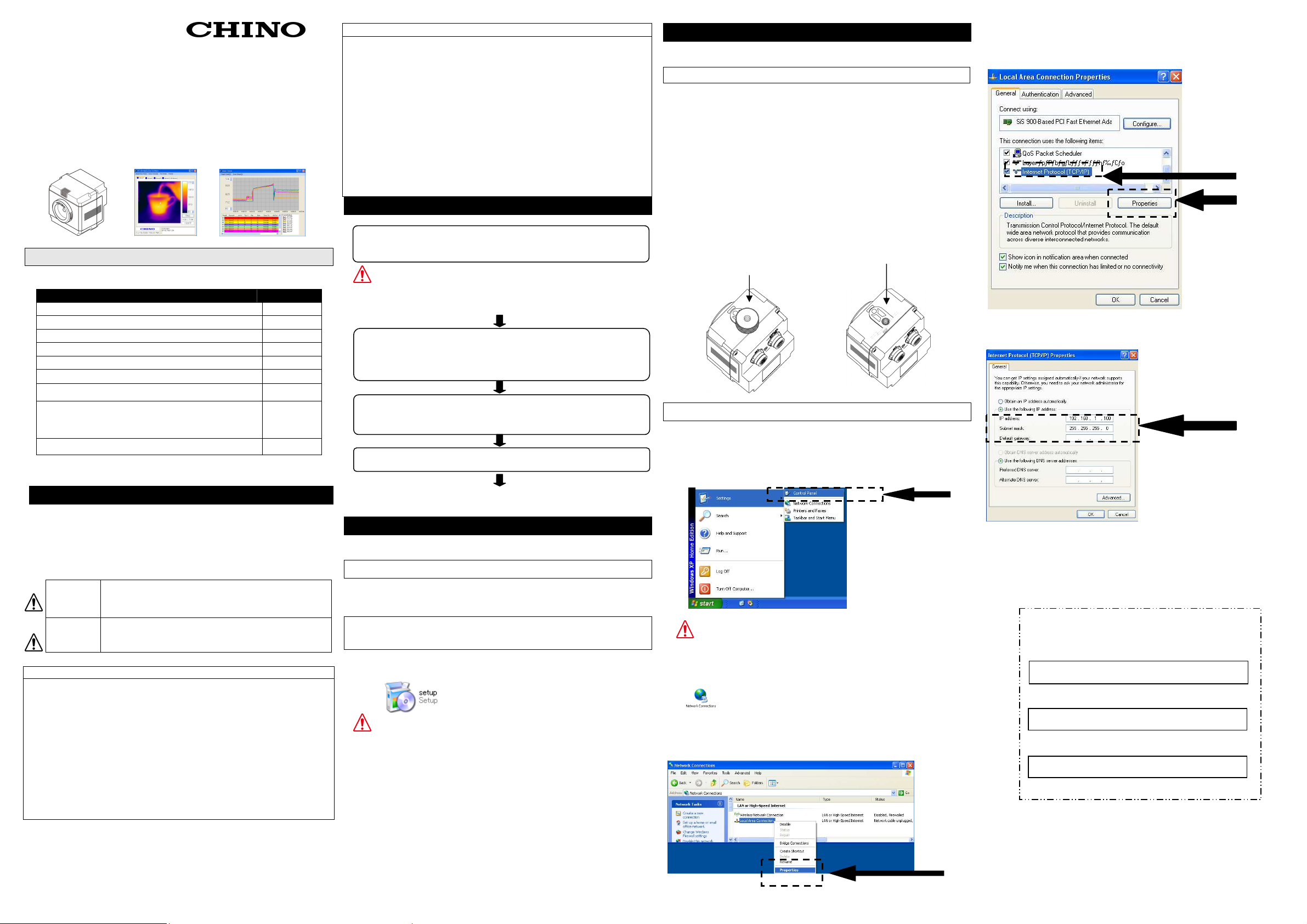
2. PC settings
According to the following procedure, you will need to
change the IP Address of your TCP/IP connection.
Start the PC.
Select [Control Panel] from Start in the menu.
The PC that you’re using now disconnected
from the network.
Take a note of the IP address, etc. and also
consult with your network administrator.
Select [Network Connections].
Select the icon of the LAN network connection (Local area
connection here) and right-click it to open a submenu. Select
Properties in the menu.
Select [Internet Protocol (TCP/IP) in the list of [This
connection uses the following items.] of [General] tab and
click [Properties].
Check [Use the following IP address:] and set the IP address,
subnet mask and default gateway.
Assign an IP address not to conflict with other instruments.
Set the following, [IP address: 192.168.1.100, Subnet mask:
255.255.255.0, Default gateway: Blank] are set. By clocking
[OK], the IP settings are entered.
[Current memorandum]
IP address
Subnet mask
Default gateway
Page 2
Iron Rainbo
w
3.Connection of thermal image sensor and PC
Connect the thermal image sensor
directly to
the PC by
④ ⑤
⑧ ⑨
HUB
Connect the custom power/alarm output cable and the
custom Network cable to the sensor.
Connect them to align the marks of [] back of the
sensor and [Arrow] on the cable connectors.
To avoid misconnections, the custom Netowrk cable is
designed not to connect to the power/alarm output
connector of the sensor. Similarly, the exclusive
power/alarm output cable cannot be connected to the
LAN connector of the sensor.
The connections are a quick-disconnect locking type.
Insert the plug until it clicks.
To unplug, hold the sliding part (that has the
[Arrow] marking on) and pull it outward.
If the “A” part is pulled, the plugs may be damaged.
Plug the connector of the custom Network cable to the
Ethernet port of a master unit (PC, etc.). And connect
the O-tip terminals of the custom power/alarm output
cable to the terminal block
Custom Network cable LAN connector
Make sure to connect the thermal image sensor to the
PC directly for LAN settings. When other instruments (in
cluding other thermal image sensors) are connected via
a hub, etc., remove them from the network to configure
so that one set of the thermal image sensor is only
connected to the PC on the network.
If the LAN settings are performed when multiple thermal
image sensors have been connected on the
not connecting
may not be configured correctly.
[] mark
[Arrow] mark
A
Plug
of 12VDC Power Supply.
LAN port
supplied cable.
the settings of thermal imaging sensor
network,
◆
Connection example of HUB (when a HUB without
automatic crossing/straight converting function is used)
Custom Network cable (Crossing cable)
Crossing/straight converting connector
PC
LAN cable (Straight cable)
4.LAN settings of thermal image sensor
Start this application software.
A warning by security software may
appear at the initial startup. Set it
up to allow the communication via this
application software
Select [Sensor Setup]
→ [Network(Sensor)] in the menu.
The following screen will appear.
Enter information into the following set
ting items.
●Sensor number
A Numbers to be assigned to each
sensor
Enter the numbers from 1 to 4.
When one sensor is only used, enter 1.
When multiple sensors are used, assign
the numbers from 1 to 4 not to overlap
each other.
●IP address
IP addresses to be allocated to sensors. Assign a unique IP
Address to the sensor(s) not to conflict with other
instruments.
●Subnet mask
Data to specify the address of network from the IP address.
Enter an arbitrary subnet mask.
●Gateway
IP address of a relaying unit in case that there is not the
designation IP address on the subnet.
When the gateway is not used, select [Disable].
After entering addresses, click [Apply].
When the transmission is completed properly, [ALL SET
OK!] is displayed on the message box.
If the data is not transmitted, confirm the connection of
network, etc. and click [Apply] button again.
By the above procedure, the LAN settings of the thermal
image sensor are completed.
Please reboot the sensor because when LED
indicator of the sensor blinks twice in purple.
When multiple thermal image sensors are used,
perform the same settings for each thermal image
sensor. In case of multiple sensors being used,
perform the LAN settings of each sensor connected to
the PC separately.
.
Initial settings of application software
These steps described here will register the sensor to be
connected
to the application software.
Select [Sensor Setup] → [IP Address] in the menu.
The following screen will appear.
Enter the following items.
●Checkboxes for Sensor 1 to
Sensor 4
Check () the checkboxes of the
sensor numbers that you want to
communicate with.
For example, when 2 thermal
image sensors are used and “1”
and “2” are allocated to these
sensors in the LAN setting of the
sensors, check () the [Sensor
1] check box and [Sensor 2]
checkbox.
●IP address
Enter the IP addresses assigned to each sensor with
the Network settings procedure.
●Sensor ID
You can give each sensor a name here.
For example, you can use location names such as furnace-1,
furnace-2, etc.
After the above items are entered, click [Apply].
By the above procedure, the initial settings of the application
software are completed.
■Displaying of thermal image
◆Color pallet
When the LAN settings of the sensors are changed,
change these settings as well, otherwise
, image and data will not be displayed correctly.
Start Application Software and he following screen will
appear. Click [Run] button on the screen.
When the IP registration to the application software
is not completed yet, the message of [No IP
Address found] will appear. Complete the
registration of IP.
[RUN] button
[When multiple sensors are connected]
When multiple sensors are connected, click the tab of the
sensor number you want to display and then perform the
above [1] and [2].
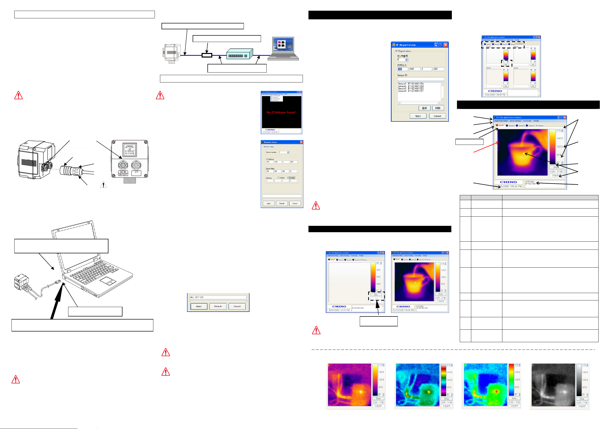
■Screen configuration and explanation
①
⑩
②
Origin (0,0)
③
No
Main Menu
①
②
Thermal Image
③
Current Time The current time of the PC is displayed.
④
Temperature
⑤
Color Palette
⑥
⑦
Temperature
Value and
⑧
Coordinate of
⑨
Indicator for
Alarm from
⑩
名 称 説 明
Bar
Sensor Tabs For selecting the sensor to be displayed
Screen
Scale
Run/Stop Run/Stop for communication.
the pixel
Sensor ID
Sensor
Gradation
Various functions offered by this application software
can be selected.
Display a 2-dimensional thermal image based on
temperature from each pixel in a 48x47 array. The frame
rate of the display is 3fps.
The coordinates of pixels displaying temperature
values are (X=0, Y=0) as the origin at the top-left
and (X=47, Y=46) at the bottom-right.
Maximum and minimum values of the temperature
scale being displayed currently. To change values,
click the Up/Down arrows mark or enter values from
the keyboard after clicking the box.
The temperature of temperature scale is displayed by
256 colors. By clicking the color palette, the
displaying color pattern of thermal image can be
changed. The default is the iron. The display pattern
can be selected from 4 kinds of iron, rainbow,
gradation and gray.
The coordinate and temperature value selected by
the sensor are displayed.
The name and IP address of the sensor displaying
the thermal image are indicated. (Enter the
sensor name in the sensor IP registration screen.)
The red/yellow colors are flashed when the alarm set
on the sensor(s) is activated. (The alarms are
displayed at the upper side of the tab of sensor.)
Gray Scale
⑥
⑦
 Loading...