

Page 1
INST-No.INE-293A
Thank you for your purchase of parameters programming software “PASS”.
Please read this instruction manual without fail for using this software correctly and safely and also
preventing troubles in advance.
1. No part of this manual can be reproduced in any form without permission.
2. For the contents of this manual, alteration is reserved without notice in the future.
3. This manual has been prepared by making assurance doubly sure about its contents.
However, if any question arises or if any error, an omission, or other deficiencies are found, please
inform your nearest CHINO’s sales agent of them.
4. You are requested to understand that CHINO is not responsible for any operation
results.
Windows and Excel are registered trademarks of Microsoft Corporation.
Other brand and product names are trademarks or registered trademarks of their respective holders.
Parameters Programming Software
PASS
Notice
Page 2

― CONTENTS ―
1.OUTLINE .................................................... 1
2.INSTALLATION AND UNINSTALLATION .. 2
2-1 Installing.......................................................................... 2
2-2 Uninstalling ..................................................................... 3
3.STARTING UP............................................ 4
3-1 How to start..................................................................... 4
3-2 Exiting ............................................................................. 4
4.SCREEN OPERATION............................... 5
4-1 Operation at starting up .................................................. 5
4-1-1 Communication parameter selection.................................................... 5
4-2 “Instrument Selection” .................................................... 6
4-3 “Programming Menu”...................................................... 7
4-3-1 Programming Menu for AL3000/AH3000 ............................................. 7
4-3-2 Programming Menu for BR series ........................................................ 8
4-3-3 Programming Menu for SE3000........................................................... 9
4-3-4 Programming Menu for LT series ....................................................... 10
4-3-5 Programming Menu for JU ................................................................. 11
4-3-6 Programming Menu for KE3000......................................................... 12
4-4 Basic operation for each screen ................................... 13
4-4-1 Operation for a programming screen with the table format ................ 13
4-4-2 Operation for setting screen with selecting style ................................ 14
4-5 File Storing (SAVE)....................................................... 15
4-6 Reading a file (LOAD) .................................................. 15
4-7 Data List........................................................................ 16
5.Cautions................................................... 17
5-1 How to deal with an abnormal quit ............................... 17
5-2 Cautions for upgrading the version............................... 17
Page 3
1.OUTLINE
This software must be installed into the hard disk of your computer just as you install other application
software for Windows. This software cannot be started from a CD-ROM.
CAUTION
“System Requirement”, “Installation Procedure” and “How To Start” are
explained below.
[System Requirements]
<Hardware>
CPU Pentium II 300MHz or faster
Memory At least 48MB (64MB recommended)
Disk drive
Communications
port
<Software>
OS Windows98/Me
WindowsNT4.0/2000/XP Home/XP Pro
* Internet Explorer 4.0 or later version is required to display the Help Contents.
CD-ROM drive : 1 drive or more (for installing PASS)
Hard disk drive : 1 drive (at least 100MB of free space) or more
*Connection with MODBUS instruments
Either 1 port of the communication ports (COM1 to COM9) supported by
Windows.
*Connection with Ethernet instruments
LAN port (10base-T) which Windows is supporting.
*Connection with USB instruments
USB port which Windows is supporting.
[Applied instruments]
By connecting the following instruments and a personal computer via a communications interface,
Parameters are programmed and displayed on a computer screen.
MODBUS
・Graphic recorder BR series
・180mm hybrid recorder AH300 series
・100mm hybrid recorder AL3000 series
・Field scanner SE3000 series
・Digital indicating controller LT series
・Thyristor regulator JU
・NETWORK LOGGER KE3000 series
Ethernet
・Graphic recorder BR series
・180mm hybrid recorder AH300 series
・100mm hybrid recorder AL3000 series
・Field scanner SE3000 series
・NETWORK LOGGER KE3000 series
USB
・NETWORK LOGGER KE3000 series
Caution:Each instrument requires a communications interface (RS-232C,/RS-422A/RS-485, Ethernet or USB)
-1-
Page 4
2.INSTALLATION AND UNINSTALLATION
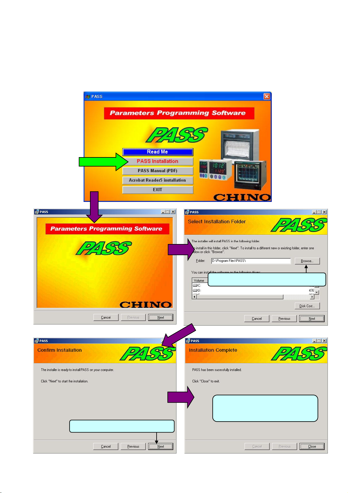
2-1 Installing
By selecting [English] in the Menu window, the window shown below will appear.
Click [PASS Installation].
Follow the instructions in the windows shown below.
Click
To install to a different folder, click [Browse].
When you have a message asking you to
restart your computer, follow the
instructions.
Click [Next] to start the installation.
-2-
Page 5
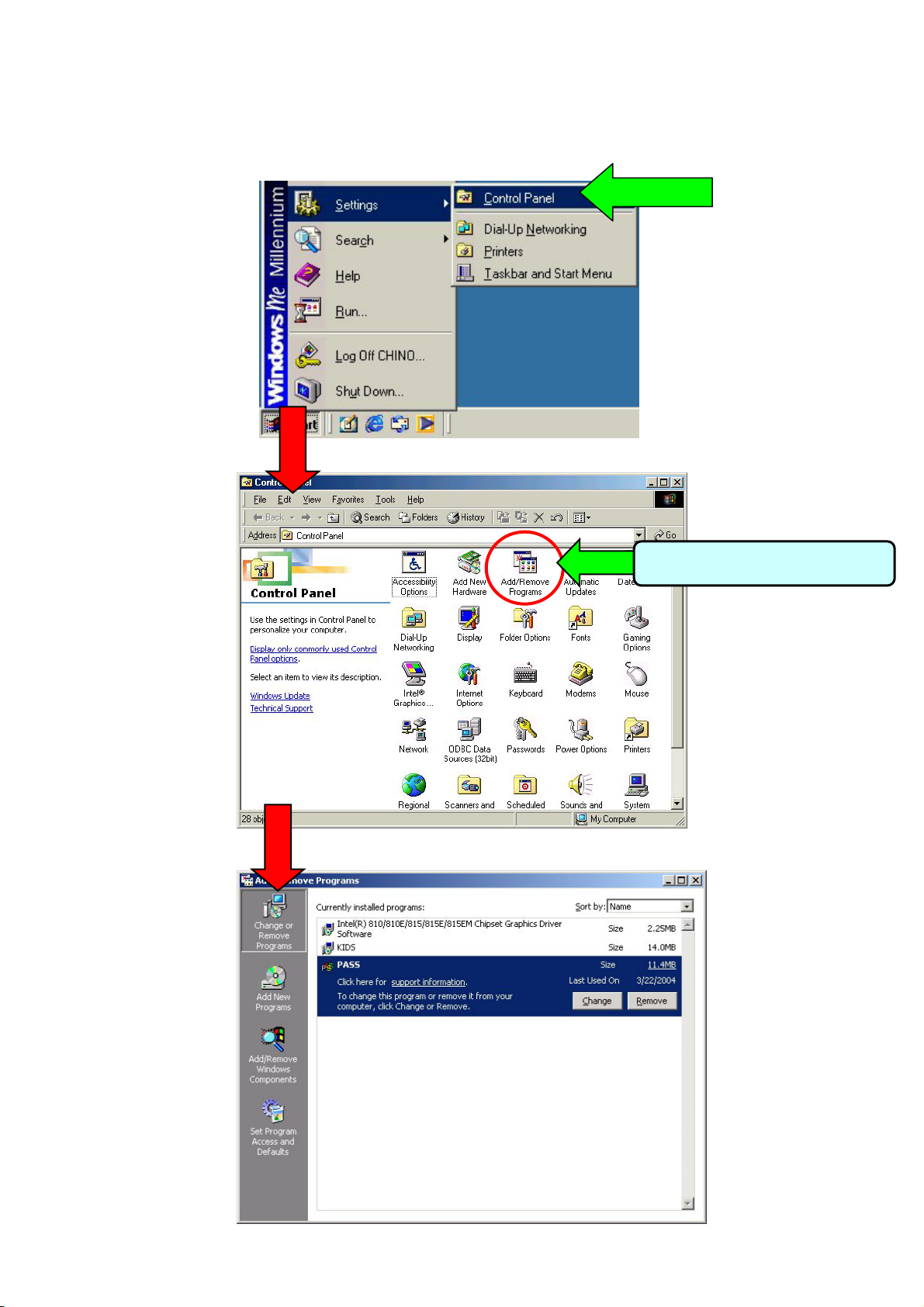
2-2 Uninstalling
Click the Start button, point to Settings, and then click Control Panel.
Click
Click
Double-click Add/Remove Programs.
-3-
Page 6
3.STARTING UP
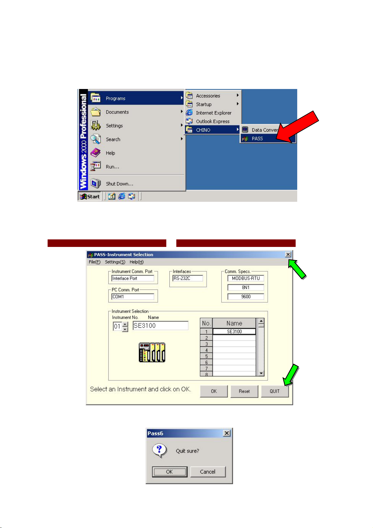
3-1 How to start
To start the program, click [Start] button, point to [Programs], point to [CHINO], and then click [PASS].
3-2 Exiting
To quit the PASS,
(1) click [Quit] on the “Instrument Selection”, or (2) click [X] in the right corner of the title bar.
②
①
In either case, a confirmation message to quit will appear. Click OK to quit PASS.
-4-
Page 7

4.SCREEN OPERATION
4-1 Operation at starting up
When you start PASS, the “Communication parameter selection” dialog box will appear.
4-1-1 Communication parameter selection
The selection of two kinds of parameters is required in the “Communication parameter selection” dialog box.
(1) Communication Port on Instruments・・・Select the programming via the “Communication Interface for PC” or the
“Engineering Port” on the instruments applied.
For the programming via the “Engineering Port”, an exclusive cable (type: RZ-EC1) is
Caution
(2)Communication Port on PC
●MODBUS・・Select the port No, protocol, bit rate for the RS232C of your personal computer
※Programming by PASS should be performed either in RTU mode or ASCII mode of the MODBUS protocol.
Caution
●Ethernet・・・Select the IP address, port No.
●USB・・・Select the address.
required.
Programming in the instruments is also required. Refer to the manuals of the
communications interfaces of the instruments.
The programming by PASS cannot be performed with CHINO’s “Private protocol”.
When KIDS, CHINO’s data acquisition software, is being executed, the programming
should be performed in RTU mode.
Programming for the instrument is also necessary by referring to the manual of the
communications interfaces of the instrument.
-5-
Page 8

4-2 “Instrument Selection”
When the above programming has been completed, the instrument to be connected is automatically detected.
When RS232C or “Engineering Port” is selected, detection will be carried out only at the “Instrument Number” 1.
In case of RS422A, Rs485 or USB, the instruments are detected in the range entered in Para. 4-1-1 from 1 to 99.
For Ethernet, IP addresses only are detected.
The detection result is displayed on the “Instrument Selection” screen. Select the instrument with the “Instrument
Number” to be programmed and click “OK”.
In case the instrument to be programmed is not displayed, check (1) communications cable and (2) communications
settings (both for the instrument and the personal computer), then click “Reset”.
At the setting (S) on the menu bar;
[Read from instrument] is selected, current parameters are read from an instrument and the menu screen for each
model will appear. Click the button of the parameter item required to program. (Refer to paragraphs after Para.
4-3-1.)
[Read from file] is selected, instrument parameters are read from a file created by [SAVE] on the menu for each
model and the menu screen will appear. Click the button of the parameter item required to program. (Refer to
paragraphs after Para. 4-3-1.)
* As the parameters are not read from an instrument, the initial startup becomes quicker.
Select the “Instrument Number”.
The instruments detected at
the “Instrument Number” 1 to
99 are displayed.
-6-
Page 9

4-3 “Programming Menu”
4-3-1 Programming Menu for AL3000/AH3000
The buttons and the related programming parameters are explained below.
Button Programming Item
“Channel Parameters 1” programming
CHpara1
CHpara2
REC
Action
MATH
OTHER
SAVE
LOAD
LIST
Select
(1)Input Kind (2)Range/Scale (3)RJ Internal/External
(4)Alarm (5)Burnout
“Channel Parameters 2” programming
(1)Tag (2)Engineering Unit (3)Color
“Printing Parameters” programming
(1)Chart Speed Periodic Data Printing Interval (2)Subtract Printing
(3)Printing Format (Automatic Range-shift Printing, Compressed/Expanded Printing,
Zone Printing)
“Printing and Operation”
(1)Feed (2)List Printing (3)Title Printing
(4)Digital Data Printing (5)Title Characters Programming
(6)Message Printing (7)Message character programming
* (6) and (7) are available in pen-type instrument only.
“Mathematics Parameters” programming
(1)Communications Input (2)Maths Functions
(3)Humidity (Humidity/Temperature Calculation)
*The maths functions available to be programmed depend on the specifications of
instruments.
“Other Parameters” programming
(1)Temperature unit (°C, °F) (2)High-speed Trace Printing (Dotting type)
(3)Alarm Dead-band (4)Instrument Time (5)Interface Specification
(6)P.O.C (7)Alarm relay (8)Remote Contact (9)Digital filter (10)Linear
*The maths functions available to be programmed depend on the specifications of
instruments.
* (5) can be programmed only from the “Engineering Port”.
* (6) to (9) are available in pen-type instruments only.
Storing a programmed parameters file into a floppy disk or a hard disk.
Click this button when storing the programmed parameters read from an instrument
into a floppy disk or a hard disk.
Reading programmed parameters file from a floppy disk or a hard disk.
Click this button when reading the programmed parameters stored at the “SAVE”.
* With this LOAD function, the parameters are only read and displayed on a personal
computer. They are not sent to an instrument. To send the parameters to an
instrument, carry out the “Send” function on each screen.
For collectively sending all parameters to an instrument, use the [Batch transmission]
in the LIST.
Display of instrument parameters list
(1)Parameters printing (printer, printing form selection, preview)
(2)File saving (saving with Excel or TXT or CSV format)
(3)Batch transmission (The parameters displayed are sent to an instrument
collectively.)
Returning to the “Instrument Selection”
Click this button when quitting programming for an instrument, starting programming
for another instrument.
-7-
Page 10

4-3-2 Programming Menu for BR series
The buttons and the related programming parameters are explained below.
Button Programming Item
“Display Parameters” programming
Display
CHconf1
CHconf2
Alarm
MATH
File
Message
Others
SAVE
LOAD
LIST
Select
(1) Screen Select ion (2) Group Display (3) Trend Display
(4) Bar-graph Display (5) Data Display
“Channel Configuration 1” programming
(1) Input Kind (2) Range/Scale
(3) RJ Internal/External (4) Burnout
“Channel Configuration 2” programming
(1) Tag (2) Engineering Unit (3) Color (4) Display Scale
“Alarm” programming
(1) Type (2) Set-point (3) Relay Number, etc.
“Mathematics Parameters” programming
(1) Communications Input (2) Maths Functions
(3) Humidity (Humidity/Temperature Calculation), etc.
*The maths functions available to be programmed depend on the
specifications of instruments.
“File” programming
Program up to 5 files.
(1) Type (2) File Name (3) File Capacity (4) Storing Channels
(5) Trigger Condition (6) Daily Report Programming
“Message” programming/operation
(1) Character Programming (2) Printing Operation
“Other Parameters” programming
(1) Guidance Language (2) Temperature Unit (°C, °F)
(3) Clock Setting (4) Time Format (5) Screen Saver
(6) Brightness (7) Operator Access Entry (8) Remote Contacts
(9) Status Output (10) Communication 1 (11) Communication 2
(12) Instruments to be connected with Communication 2
* The functions available to be programmed depend on the
specifications of instruments.
* (10) can be programmed only from the “Engineering Port”.
Storing a programmed parameters file into a floppy disk or a hard
disk.
Click this button when storing the programmed parameters read
from an instrument into a floppy disk or a hard disk.
Reading a programmed parameters file from a floppy disk or a
hard disk.
With this LOAD function, the parameters are only read and displayed
on a personal computer. They are not sent to an instrument. To send
the parameters to an instrument, carry out the “Send” function on
each screen.
For collectively sending all parameters to an instrument, use the the
[Batch transmission] in the LIST.
Display of instrument parameters list
(1)Parameters printing (printer, printing form selection, preview)
(2)File saving (saving with Excel or TXT or CSV format)
(3)Batch transmission (The parameters displayed are sent to an
instrument collectively.)
Returning to the “Instrument Selection”
Click this button when quitting programming for an instrument,
starting programming for another instrument.
-8-
Page 11

4-3-3 Programming Menu for SE3000
The buttons and the related programming parameters are explained below.
Button Programming Item
“Channel Configuration” programming
CHpara
SUB “Subtract Parameters” programming
MATH
Other
SAVE
LOAD
LIST
Select
(1) Input Kind (2) Range/Scale (3) RJ Internal/External (4)Alarm
(5) Burnout
“Mathematics Parameters” programming
(1) Maths Functions
(2) Humidity (Humidity/Temperature Calculation), etc.
“Other Parameters” programming
(1)Temperature Unit (°C, °F) (2)Alarm Deadband
(3)Interface Specification
*The functions available to be programmed depend on the specifications of
instruments.
* (3) can be programmed only from the “Engineering Port”.
Storing a programmed parameters file into a floppy disk or a hard disk.
Click this button when storing the programmed parameters read from an
instrument into a floppy disk or a hard disk.
Reading a programmed parameters file from a floppy disk or a hard disk.
With this LOAD function, the parameters are only read and displayed on a personal
computer. They are not sent to an instrument. To send the parameters to an
instrument, carry out the “Send” function on each screen.
For collectively sending all parameters to an instrument, use the [Batch
transmission] in the LIST.
Display of instrument parameters list
(1)Parameters printing (printer, printing form selection, preview)
(2)File saving (saving with Excel or TXT or CSV format)
(3)Batch transmission (The parameters displayed are sent to an instrument
collectively.)
Returning to the “Instrument Selection”
Click this button when quitting programming for an instrument, starting
programming for another instrument.
-9-
Page 12

4-3-4 Programming Menu for LT series
The buttons and the related programming parameters are explained below.
Button Programming Item
“RUN parameters” programming
RUN
Input
Control
EVENT
OUTPUT
Option
OTHER
SAVE
LOAD
LIST
SELECT
* For parameters covered by , programming by LT200,/ LT300 or LT800 is disabled.
*Depending on specifications of instruments, some parameter items cannot be programmed.
(1)SV selection (2)SV,PID,Event Setting (3)RUN/READY
(4)AUTO/MANUAL Operation (5)Auto Tuning (6)Target value filter
(7)Key lock
“Input parameters” programming
(1)Input Kind (2)Temperature Unit (3)Range/Scale (4)PV,SV dot
(5)Sensor correction (6)Digital filter (7)Deviation dead-band (8)Burnout
“Control parameters” programming
(1)SV,PID,Dead-band (2)Ramp、Ramp unit,PV start
(3)SV limit (4)ARW,Output preset
“Event parameters” programming
(1)mode、Dead-band、Phase、Delay (2)Event Setting、Stand-by
(3)Output at Ready
“Output parameters” programming
(1)output limit、Variation (2)Feed Back (3)Power recovery action
(4)Control action (5)PV error output、Preset-out(Output at Ready)、Pulse cycle
“Option parameters” programming
(1)Remote Contact (2)Transmission (3)Remote signal
“Other Parameters” programming
(1)Heat/Cool、Split (2)Cooling P、Cooling pulse cycle
(3)Split Parameter
Storing a programmed parameters file into a floppy disk or a hard disk.
Click this button when storing the programmed parameters read from an instrument into
a floppy disk or a hard disk.
Reading a programmed parameters file from a floppy disk or a hard disk.
With this LOAD function, the parameters are only read and displayed on a personal
computer. They are not sent to an instrument. To send the parameters to an instrument,
carry out the “Send” function on each screen.
For collectively sending all parameters to an instrument, use the [Batch transmission] in
the LIST.
Display of instrument parameters list
(1)Parameters printing (printer, printing form selection, preview)
(2)File saving (saving with Excel or TXT or CSV format)
(3)Batch transmission (The parameters displayed are sent to an instrument collectively.)
Returning to the “Instrument Selection”
Click this button when quitting programming for an instrument, starting programming for
another instrument.
-10-
Page 13

4-3-5 Programming Menu for JU
The buttons and the related programming parameters are explained below.
Button Programming Item
“Parameters” programming
Setting
SAVE
LOAD
List
select
(1)AUTO/MANUAL (2)Settings (3)Phase angle/Zero-cross
(4)Current limit function (5)Disconnection alarm function
(6)Key lock (7) Run/Stop
Storing a programmed parameters file into a floppy disk or a hard disk.
Click this button when storing the programmed parameters read from an instrument into
a floppy disk or a hard disk.
Reading a programmed parameters file from a floppy disk or a hard disk.
With this LOAD function, the parameters are only read and displayed on a personal
computer. They are not sent to an instrument. To send the parameters to an instrument,
carry out the “Send” function on each screen.
For collectively sending all parameters to an instrument, use the the [Batch
transmission] in the LIST.
Display of instrument parameters list
(1)Parameters printing (printer, printing form selection, preview)
(2)File saving (saving with Excel or TXT or CSV format)
(3)Batch transmission (The parameters displayed are sent to an instrument collectively.)
Returning to the “Instrument Selection”
Click this button when quitting programming for an instrument, starting programming for
another instrument.
-11-
Page 14

4-3-6 Programming Menu for KE3000
The buttons and the related programming parameters are explained below.
Button Programming Item
“Channel Configuration” programming
CHpara
(1) Input Kind (2) Range/Scale (3) RJ Internal/External (4)Alarm
(5) Burnout (6)Sensor correction (7)digital filter
Relay
Other
SAVE
LOAD
LIST
Select
“Relay Output” programming
(1)Alarm bit mask (2)ON/OFF delay time (3)phase
“Other Parameters” programming
(1)USB address (2)Eng port Specification (3)interface Specification
*(1) can be programmed only from the “Engineering Port” or “Communication 1”.
*(2) can be programmed only from the “USB” or “Communication 1”.
*(3) can be programmed only from the “Engineering Port” or “USB”.
Storing a programmed parameters file into a floppy disk or a hard disk.
Click this button when storing the programmed parameters read from an instrument into
a floppy disk or a hard disk.
Reading a programmed parameters file from a floppy disk or a hard disk.
With this LOAD function, the parameters are only read and displayed on a personal
computer. They are not sent to an instrument. To send the parameters to an instrument,
carry out the “Send” function on each screen.
For collectively sending all parameters to an instrument, use the the [Batch
transmission] in the LIST.
Display of instrument parameters list
(1)Parameters printing (printer, printing form selection, preview)
(2)File saving (saving with Excel or TXT or CSV format)
(3)Batch transmission (The parameters displayed are sent to an instrument collectively.)
Returning to the “Instrument Selection”
Click this button when quitting programming for an instrument, starting programming for
another instrument.
-12-
Page 15

4-4 Basic operation for each screen
r
g
Two kinds of programming, a table format and a selecting format, are available.
4-4-1 Operation for a programming screen with the table format
The followings are the procedure to operate the programming screen.
(1)Click the cell where you want to change a parameter. (Entering of numeric values via the keyboard is enabled.)
(2)Change a parameter on the programming menu or select a parameter from the list.
(3)Send the reprogrammed parameters to the instrument by clicking on the “Trans” button.
[Example: CH parameters for KE3000]
Send the parameters to the
instrument.
Caution
Caution
Programming to the instrument will not be carried out without executing “Send (Trans)”
operation.
After executing “Send” operation, the instrument cannot be returned to the condition with
the previous parameters even if the “Cancel” button is pressed.
Observe the following cautions for programming.
Click a cell to change a
parameter.
(1)With the programming window, spaces for several digits are prepared for Tag and
Engineering unit, however, the effective number of characters is decided.
(2)Engineering units are merely symbols. When the Engineering unit is changed from
°C to °F, it has no effect on the temperature unit system.
(3)When a decimal point place at the minimum side of the range and the scale is
changed, a decimal point place at the maximum side of the range and the scale,
and the related alarm setpoint will also be changed. Be sure to check this when
you perform such a change.
Click to copy parameters to
channels.
othe
Numeric values can be entered
with a mouse on the numeric
value enterin
window.
-13-
Page 16

4-4-2 Operation for setting screen with selecting style
The followings are the procedure to operate the programming screen.
(1)Click the item that you want to select.
(2)Send the reprogrammed parameters to the instrument by clicking on the “Trans” button.
[Example: Recording formats for AL3000/AH3000]
Returns to the “Programming Menu”.
Select the item.
Send the parameters to the
instrument.
-14-
Page 17

4-5 File Storing (SAVE)
When the SAVE button is clicked, the following window is displayed. Specify the name of the file and
the place where the programmed parameters are to be stored. The programmed parameters are stored by clicking
“SAVE”.
Caution
Any file name may be chosen, however, extension is fixed to CSV.
4-6 Reading a file (LOAD)
When the LOAD button is clicked, the following window is displayed. Specify the file name and the
place where the programmed parameters have been stored. The programmed parameters are read out by clicking
“OPEN”.
Be sure to select the file stored with SAVE function.
Caution
If any file other than the file stored with the SAVE function is selected or
any alteration is done to a file stored with the SAVE function, PASS might
quit.
-15-
Page 18

4-7 Data List
By clicking this button , the screen show below will appear.
The icons displayed in the Data list are:
Quits the Data list
Settings for printing of the Data list
A print preview of the Data list will appear.
Prints the Data list.
Stores the Data list into an Excel file or csv or tab delimit text format file.
(Reading of this file with [LOAD] on each menu bar is disabled.)
The parameters are sent to the instrument collectively.
* This icon may not be displayed depending on models of instruments.
The Help file will appear.
-16-
Page 19

5.Cautions
5-1 How to deal with an abnormal quit
Restart the PASS when it quits unexpectedly or stops its operation because of an abnormality occurring in the
operating system, shortage of memory or when executing background application software.
5-2 Cautions for upgrading the version
The PASS is subject to be upgraded for adding instruments to be applied.
(1)When upgrading a version, uninstall the current version (2-2)then
(2) install the new version.
To uninstall an old version of PASS, follow the “Add/Remove Programs”
Caution
procedure of Windows, which is explained below. You cannot uninstall the PASS
with a Delete function (“drag and drop” the file into a “Recycle Bin”).
-17-
Page 20

32-8, KUMANO-CHO, ITABASHI-KU, TOKYO 173-8632
Telephone : 81-3-3956-2171
Facsimile : 81-3-3956-0915
Printed in Japan ( )
 Loading...