

Page 1
INST.No.INE-364
LE5100
Hybrid Recorder
LE5200
Operation Type Intelligent Recorder
【I. Instruction Manual】
Page 2

Page 3
◆Introduction/Request, Warranty Period, and Notices
p
Thank you for your purchase of LE5 series hybrid recorder having a 250mm recording width.
Please read this instruction manual without fail for correctly and safely operating this unit and
also
Separate instruction manual
This manual covers the operation of standard specifications and connection methods of a part of options.
For operating each option, please read their instruction manuals together with this manual.
Request
reventing troubles in advance.
1. To instrumentation, installation, and sales contractors
Be sure to pass this instruction manual to the user who uses this unit.
2. To the user
This instruction manual is also necessary for maintenance. Keep this manual
carefully until the unit is discarded.
Notice
1. No part of this manual can be copied or reproduced in any form.
2. Alteration of the description contents in this manual is reserved without notice.
3. For the contents of this manual, we make assurance doubly sure. However, if a doubtful
point, an error, and/or a description failure should have found, please inform your nearest
branch or sales office.
4. You are requested to understand that we are not responsible for any operation results.
Warning
Perchlorate Material
This instrument uses battery with Perchlorate Material.
Special handling may apply, see
http://www.dtsc.ca.gov/hazardouswaste/perchlorate
Page 4
Cautions for safe use
Observe the following cautions for using this unit safely.
1. Mounting place and terminal cover
①Panel mount type
This unit is designed to be mounted on an indoor instrumentation panel. For using this unit, mount it on the
panel without fail. Take an electric shock preventive measure so that the user cannot directly touch any
power supply or input/output terminals.
Portable type
②
Mount an electric shock preventive cover to the terminal block.
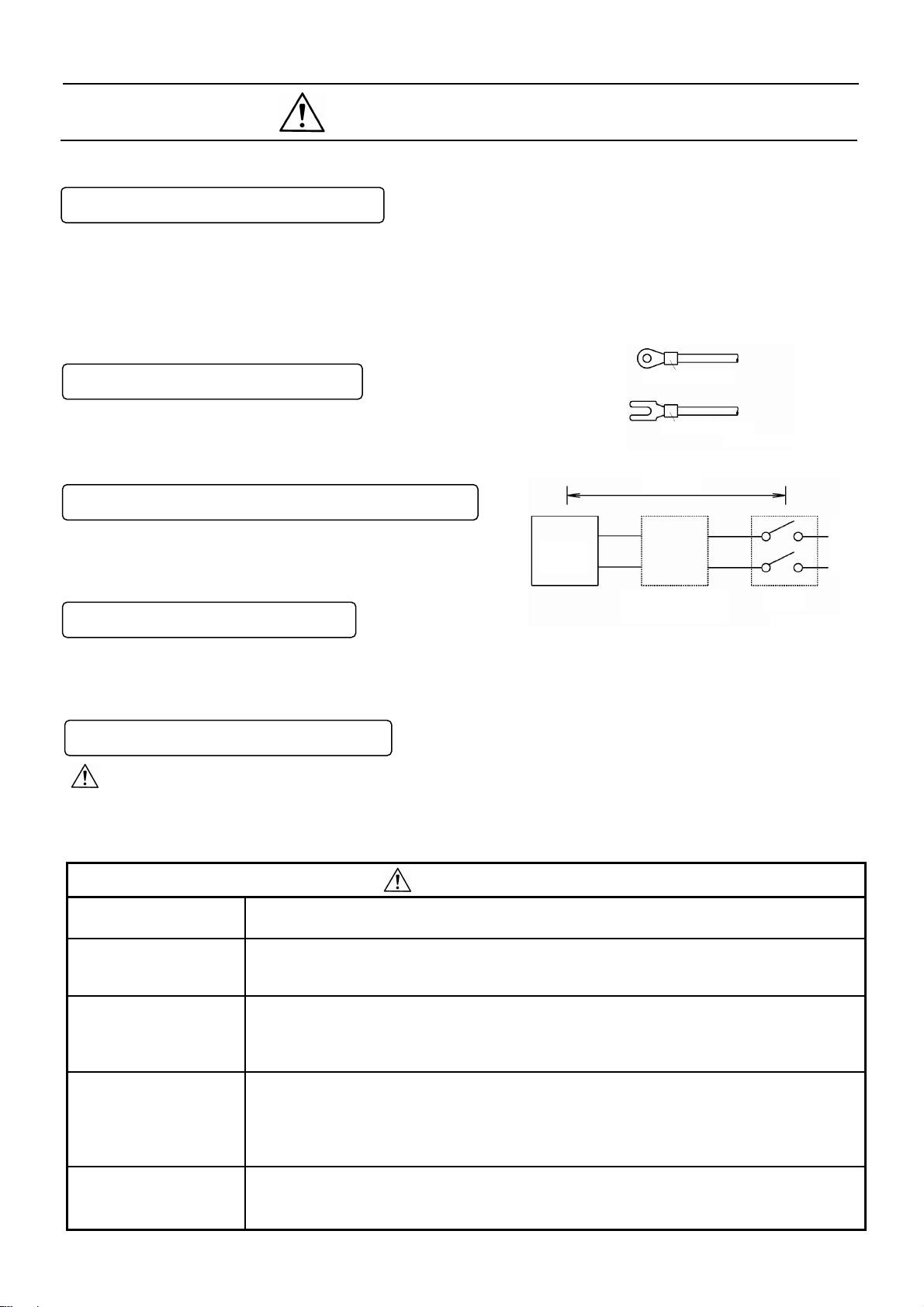
2. Termination of wire connections
For terminating wires to the terminals, use insulation sleeve
crimp style terminals. For power terminals and protective
grounding terminal, use O-type insulation sleeves.
3. Mounting of a breaker to the feed power supply
Mount a switch conforming to the rated power supply of this
unit and an over-current protective device to the power
supply of this unit at an easy-to-access position within 3m.
4. A safety measure to the output
Take a safety measure on the final product side as occasion demands when a control output or an alarm
output is provided, otherwise an output failure of this unit may occur due to wrong operation, troubles, an
abnormal sensor, or other failures.
5. Symbol marks employed in this unit
This symbol mark indicates a position where an electric shock accident may occur. Particularly be careful
not to receive any electric shock during connections, check, and maintenance work.
This symbol shows a protective grounding terminal. Connect the instrument being indicated by this mark to
the protective ground of the power supply equipment before starting its operation.
Type O
Type Y
This unit
Insulation sleeve
Insulation sleeve
Within 3m
An over-current
protective device
Switch
Feed
power
supply
Power voltage and
protective grounding check
Don’t put your hand into
the case
Stop feeding the power
supply if an abnormal
symptom occurs
Repair and modifications
Use according to the
instruction manual
Warnings
Check if connections are correct, the power voltage conforms to the specified voltage, and also the
protective grounding is done without fail before feeding the power supply.
Don’t put your hand into the internal unit (rack) or case, except for the positions where are
necessary for operating the unit, otherwise you may receive an electric shock or you may be
injured.
If abnormal odor, abnormal noises, smoke, or other abnormal symptoms occur or if the unit is too
hot to touch it by hand, these symptoms show a dangerous condition. Turn off the feed power
supply at once, and contact your nearest branch or sales office or the sales agent from which you
have bought your unit.
If repair or modifications are necessary, please contact your nearest branch or sales office or the
sales agent from which you have bought your unit.
<Caution>
Don’t repair the unit by replacing its parts or modify it by any person other than a service
engineer approved by our company.
For using this unit correctly and safely, use it according to this instruction manual.
You are requested to understand that we are not responsible for any injures, damage, loss of
profits or any other claims that were caused by wrong uses.
Page 5

CONTENTS
LE5100
Hybrid Recorder
LE5200
Operation Type Intelligent Recorder
1. Introduction
1-1 LE5100/LE5200 ・・・・・・・・・・・・・・・・・・・・・・・・・・・・
1-2 Profile ・・・・・・・・・・・・・・・・・・・・・・・・・・・・・・・・・・・・
1-3 Input types ・・・・・・・・・・・・・・・・・・・・・・・・・・・・・・・・
1-4 Check and confirmation
1-4-1 Appearance check ・・・・・・・・・・・・・・・・・・・・・・
1-4-2 Attachments check ・・・・・・・・・・・・・・・・・・・・・
1-4-3 Type code No. check ・・・・・・・・・・・・・・・・・・・・
1-5 Major functions ・・・・・・・・・・・・・・・・・・・・・・・・・・・・・
・・・・・・・・・・・・・・・・・・・・
2. Names and functions of components
2-1 Front section ・・・・・・・・・・・・・・・・・・・・・・・・・・・・・・
2-2 Front section of internal unit ・・・・・・・・・・・・・・・・・
2-3 Display (status) ・・・・・・・・・・・・・・・・・・・・・・・・・・・・
2-4 Keyboard ・・・・・・・・・・・・・・・・・・・・・・・・・・・・・・・・・
3. Mounting method
3-1 Selection of mounting place ・・・・・・・・・・・・・・・・・
3-1-1 Ambient temperature and humidity ・・・・・・・
3-1-2 Factory environment ・・・・・・・・・・・・・・・・・・・・
3-1-3 Mounting angle ・・・・・・・・・・・・・・・・・・・・・・・・
3-2 Panel mounting method ・・・・・・・・・・・・・・・・・・・・・
3-2-1 External dimensions ・・・・・・・・・・・・・・・・・・・・
3-2-2 Panel cutout ・・・・・・・・・・・・・・・・・・・・・・・・・・・
3-2-3 Mounting method ・・・・・・・・・・・・・・・・・・・・・・・
4. Connections
4-1 Cautions on connections ・・・・・・・・・・・・・・・・・・・
4-2 Terminal boards (rear panel) ・・・・・・・・・・・・・・・・・
4-3 Connections of each terminal board ・・・・・・・・・・
4-3-1 Measuring input terminal board ・・・・・・・・・・
4-3-2 Power terminals ・・・・・・・・・・・・・・・・・・・・・・・・
4-3-3 Communication I/F terminals, contact output
terminals, and external drive terminals ・・・・
4-3-4 Alarm output terminals ・・・・・・・・・・・・・・・・・・
5. Installation of auxiliary products
5-1 Mounting method of chart ・・・・・・・・・・・・・・・・・・・・
5-2 Ribbon cassette mounting method ・・・・・・・・・・・・
6. Operation
6-1 Turning on the power supply ・・・・・・・・・・・・・・・・
6-2 Display mode selection ・・・・・・・・・・・・・・・・・・・・・
6-3 Recording operation ・・・・・・・・・・・・・・・・・・・・・・・・
7. Initial setting at the delivery time from
the factory
7-1 Setting items at the delivery time from the
factory ・・・・・・・・・・・・・・・・・・・・・・・・・・・・・・・・・・・
7-2 Mode change by soft switch ・・・・・・・・・・・・・・・・・
1-1
1-1
1-1
1-1
1-1
1-1
1-2
1-3-4
2-1
2-1
2-1-2
2-3
3-1
3-1
3-1
3-1
3-1
3-1
3-1
3-1
4-1
4-1
4-2
4-2
4-2
4-3-4
4-4
5-1
5-2
6-1
6-1
6-2
7-1
7-2
Page 6

8. Setting and changes by key operation
8-1 Basic rules ・・・・・・・・・・・・・・・・・・・・・・・・・・・・・
1. Setting items and setting parameters ・・・・・・・
2
. Calling of setting items ・・・・・・・・・・・・・・・・・・・
3. Calling of setting parameters ・・・・・・・・・・・・・・
4. Acceptance and acceptance failure of keys
5. No. of parameters by setting items ・・・・・・・・・
6. Confirmation of setting parameters ・・・・・・・・・
7. Setting change ・・・・・・・・・・・・・・・・・・・・・・・・・・
8. Switching of keys ・・・・・・・・・・・・・・・・・・・・・・・・
9. Setting change mark ・・・・・・・・・・・・・・・・・・・・・
10. Setting decision function ・・・・・・・・・・・・・・・・・・
11. Basic entry of setting parameters ・・・・・・・・・・
8-2 Display setting ・・・・・・・・・・・・・・・・・・・・・・・・・・
8-3 Channel parameter setting ・・・・・・・・・・・・・・・
1. Operation recording・・・・・・・・・・・・・・・・・・・・・・・
2. Data communication input・・・・・・・・・・・・・・・・・・
8-4 Dot setting ・・・・・・・・・・・・・・・・・・・・・・・・・・・・・
8-5 Chart recording setting ・・・・・・・・・・・・・・・・・・
8-6 Alarm setting ・・・・・・・・・・・・・・・・・・・・・・・・・・・
8-7 Differential recording setting ・・・・・・・・・・・・・・
8-8 Message printing setting ・・・・・・・・・・・・・・・・・
8-9 List printing setting ・・・・・・・・・・・・・・・・・・・・・・
8-10 Data interval recording setting ・・・・・・・・・・・
8-11 Logging recording setting ・・・・・・・・・・・・・・・
8-12 Data print recording setting ・・・・・・・・・・・・・
8-13 Display setting ・・・・・・・・・・・・・・・・・・・・・・・・
8-14 Engineering port setting ・・・・・・・・・・・・・・・・
8-15 Date and time setting ・・・・・・・・・・・・・・・・・・・
8-16 System setting ・・・・・・・・・・・・・・・・・・・・・・・・
8-17 PC card (memory card) setting・・・・・・・・・・・
8-17-1
8-17-2
8-17-3
8-17-4
8-17-5
8-17-6
8-17-7
8-17-8
8-17-9
8-17-10 PC card removing・・・・・・・・・・・・・・・・・・・
Summary・・・・・・・・・・・・・・・・・・・・・・・・・・
Mounting・・・・・・・・・・・・・・・・・・・・・・・・・・
Operation・・・・・・・・・・・・・・・・・・・・・・・・・・
Handling of PC card・・・・・・・・・・・・・・・・・
PC card setting・・・・・・・・・・・・・・・・・・・・・
Setting of measuring data saving by PC
card・・・・・・・・・・・・・・・・・・・・・・・・・・・・・・・
Setting of set value saving by PC card
Setting of reading out a set value by PC
card・・・・・・・・・・・・・・・・・・・・・・・・・・・・・・・
PC card format・・・・・・・・・・・・・・・・・・・・・
・
8-1
8-1
8-1
8-1
8-1
8-1
8-1-3
8-4
8-4
8-4
8-4
8-5-6
8-7
8-8-9
8-10
8-11
8-12
8-13-14
8-15-17
8-18-20
8-21
8-22
8-23
8-24
8-25
8-26
8-27
8-28
8-29
8-30
8-30
8-30
8-30
8-31
8-31
8-32
8-33
8-34
8-35
8-36
9. Adjustment function
9-1 Zero and span adjustment of analog
recording ・・・・・・・・・・・・・・・・・・・・・・・・・・・
9-2 Zero and span adjustment of measured
values ・・・・・・・・・・・・・・・・・・・・・・・・・・・・・
9-3 Shift adjustment of measured
values・・・・・・・・・・・・・・・・・・・・・・・・・・・・・・・
9-4 Calibration・・・・・・・・・・・・・・・・・・・・・・・・・・・
10. Troubleshooting
Troubleshooting table ・・・・・・・・・・・・・・・・・・・・
11. Maintenance and check
Maintenance and check ・・・・・・・・・・・・・・・・・・
11-1 Recommendable parts exchange
cycles ・・・・・・・・・・・・・・・・・・・・・・・・・・・・・
11-2. Disposal・・・・・・・・・・・・・・・・・・・・・・・・・・・・
12. General specifications
General specifications ・・・・・・・・・・・・・・・・・・・・
13. Option specifications
Option specifications ・・・・・・・・・・・・・・・・・・・・・
13-1. External drive・・・・・・・・・・・・・・・・・・・・・・・
13-2. Alarm output・・・・・・・・・・・・・・・・・・・・・・・・
13-3. Recording format・・・・・・・・・・・・・・・・・・・・
13-3-1. Automatic range selection recording
13-3-2. Partial compression and expansion
recording・・・・・・・・・・・・・・・・・・・・・・・・
13-3-3. Parallel scale recording・・・・・・・・・・・
13-4. Rate-of-change alarm/Differential alarm
13-4-1. Rate-of –change alarm・・・・・・・・・・・・
13-4-2. Differential alarm・・・・・・・・・・・・・・・・・
13-5. Operation ・・・・・・・・・・・・・・・・・・・・・・・・・・
9-1
9-2
9-3
9-4
10-1
11-1
11-2
11-2
12-1-5
13-1
13-2-4
13-5
13-6
13-7
13-8
13-9
13-10
13-10
13-11
13-12-16
Page 7
1. Introduction
1-1 LE5100/LE5200
This hybrid recorder having a 250mm chart measures
and records temperature (thermocouple, resistance
thermometer bulb) inputs, DC voltage (mV, V) inputs,
and other various industrial variables.
1) High speed input entry and high-speed recording
This unit scans test data, inspection data,
experimental data, and multi-point data in quick
change processes at a ratio of 36 points/100ms, and
records them at a rate of approx. 1 line/3s.
2) High precision
The accuracy rating of measuring ranges is ±0.05%,
and the maximum resolution is 1µV or 0.1℃.
3) Easy operation
Various setting can be done in the conversational
mode without any complicated operation unlike in
general high-grade units. Setting can also be done by
a personal computer or a PC card.
4) Noise resistance
This unit is characterized with a high induction noise
resistance of 130dB in common mode and 50dB in
series mode. For impulse noises, an individual filter is
provided every channel.
1-2 Profile
This unit comprises a 12-point input type, a 24-point
input type, and a 36-point input type. This unit can be
operated and set without opening the door in all
types.
1-3 Input types
This unit is characterized with a full multi range of
thermocouple (TC), resistance thermometer bulb,
and DC voltage (mV, V) inputs.
1-4 Check and confirmation
Check the unit for the following items before
operating it.
1-4-1 Appearance check
After unpacking, check the following items to see if
the unit is normal in appearance.
① Check if the front glass is free of breakage and
flaws.
② Check if the door can be opened and closed
smooth.
③ Check if the entire case is free of flaws and dirt.
1-4-2 Attachments check
The following attachments are contained.
Article names Quantity Remarks
① Ribbon cassette
② Chart ※
③ Lubricating oil (10cc)
④ Terminal screw (spare)
⑤ Mounting bracket and
mounting screw
⑥ Wrench
⑦ Instruction manual
Attachments table
1 pc. For recording
2 boxes Each contains 2 pads
1 bottle For maintenance
5 pcs. M3.5 x 8
4 pcs.
each
1 pc.
1 pad
For mounting the panel
For mounting the panel
※ Standard chart is chart No. LE-01001A. Its ordering
unit is one large box (containing 15 pads).
1-1
Page 8
1-4-3 Type code No. check
The operation may change according to the types. Confirm the type of your unit.
■ Type tab l e
LE5□□□-□□□
Model
1: LE5100 2: LE5200
No. of input points (analog inputs)
0: None 1: 12 points 2: 24 points 3: 36 points
No. of alarm output points (option)
0: None 1: 12 points 2: 24 points 3: 36 points
Alarm output is a mechanical relay ‘a’ contact output.
Communications interface Contact 1 output (option)
N: None
1: Either RS-422A or RS-485 + Ethernet
+ Contact 1 output (Contact 1output is a mechanical relay ‘a’ contact
output)
External drive (option)
N: Not provided
1: Provided
Chart speed selection (3 speeds + stop) Data printing start
Others (option)
N: None
1: Recording format + change ratio/differential alarm
2: Recording format + change ratio/differential alarm
+ arithmetic operation (In case of selecting LE5200 only)
Type: LE52
LE5133-112
LE061A001
MADE IN JAPAN
□□-□□2
When select LE5200 in model, others (option) is fixed [2].
1-2
Page 9
1-5 Major functions
This unit provides various functions. For details of setting and operation, refer to each item No.
Functions Items Contents Page No.
Measuring data in each channel are displayed.
Channel No. (3 digits) + tag (8 digits) + range (3 digits) + measured value (7 digits)
An 8-digit tag can be set and displayed.
In case of collective display of 36 points, 5-digit display is done by justifying left
digits.
A unit can also be displayed instead of the tag, and its display mode is the same
as in the tag. (Simultaneous display of both tag and unit cannot be done.)
1) Each measuring data is fixed or sequentially displayed every channel.
2) 12-point measuring data are displayed collectively.
3) 24-point measuring data are displayed collectively.
4) 36-point measuring data are displayed collectively.
※ The update cycle of 1 channel display is 2 seconds as a factory delivery value
(default).
5) In case of 24 or 36 input points, each measuring data is fixed or sequentially
displayed every 12 points.
※ The update cycle of 12・24・36 points display is 3 seconds as a factory delivery
value (default).
6) The type code, serial No., and version No. of software of this unit are indicated.
The chart speed, date (year, month, day), and time are indicated at all times
in all display modes 1) - 6).
1) KEY LOCK : Indicated when operation keys are locked.
2) CHART END : Indicated when the chart comes to an end.
3) FAIL : Indicated when the unit is in trouble.
1) Measuring data in an alarm channel are displayed red.
※ Red ALM LED flickers.
Setting conditions can be confirmed by displaying various parameters by means
of key operation.
Setting inputs and arithmetic results can be recorded by max. 36 channels,
respectively.
A recording color can be designated optionally every channel (out of 10 colors).
Tag numbers (channel numbers) are printed beside the trend recording at a fixed
interval.
When an alarm occurred or when the alarm was reset, _ (red) or_ (green) mark is
printed beside the trend recording, and also, the time, channel number, and kinds
of levels are printed at the right end of the chart.
A designated channel can be skipped.
Parallel recording, partially compressed/enlarged recording, and automatic range
selection recording can be selected.
Digital recording is done at an optional interval (time and minute) from a
designated start time by overlapping it with analog recording.
Digital recording is done at an optional interval (time and minute) from a
designated start time.
Measuring data, tag number, unit, chart speed, date (year, month, day), and time
are printed. Three kinds of recording formats can be designated optionally.
1) A difference of measuring data between designated channels is recorded in an
optional designated channel.
2) A difference between measuring data of a designated channel and the
reference value (optional setting) can be recorded in an optional designated
channel.
1) The maximum, minimum, average, and total values of measuring data between
designated channels are recorded in an optionally designated channel.
2) A time series change (maximum, minimum, average, and integration) at an
optional interval of measuring data between designated channels can be
recorded in an optional channel from a designated start time.
3) Perform function mathematics which can be shown numerical formula, and
record optional channel.
1. Digital display
2. Analog
recording
3. Digital
recording
4. Arithmetic
results
recording
①Measuring data display
②Display mode
③Status display
④Alarm status display
⑤Setting data display
①No. of recording points
②Recording color
designation
③Tag number printing
④Scale and unit printing A scale and a unit are printed at both ends of the chart every fixed time.
⑤Alarm mark printing
⑥Skip function
⑦Analog recording format
(option)
①Data interval recording
②Data printing Digital recording is done at the requested time while interrupting analog recording.
③Logging recording
④Digital recording format
⑤Skip function A designated channel can be skipped.
①Differential recording
② Arithmetic results
recording (option)
Page 2-2
Page 2-2
Page 2-1
Page 2-2
Page 2-1
Page 2-2
Page 8-1
Page 8-10
Page 8-10
-
-
-
Page 8-10
-
Page 8-21
Page 6-2
Page 8-22
Page 8-21
Page 8-23
Page 8-8
Page 8-16
-
1-3
Page 10
Functions
5. Digital printing
6. Parameter entry
7. Self diagnostic
function
8. Communication
function USB:
Standard
RS-422A/485
Ethernet (option)
9. Auxiliary
functions
Items Contents
① Year, month, day,
and time printing
② List printing
③ Message printing
④Title printing (option)
① Operation keys
② PC card
③ PC setting
①Self check function Instrument conditions are checked by executing self-diagnosis at all times.
② Setting decision
function
③Hardware check
function
① Setting All parameters can be set and confirmed.
② Operation
③ Data output Measuring data are output according to the request from the host CPU.
④Kinds
① Input value
correction function
② Recording correction
function
③ Parameter protection
function
④ Burnout function
Year, month, day, and time (time line) are printed at a designated interval.
1) A list of all parameters is printed at a requested time.
2) A list of designated parameters is printed at a requested time.
1) A message of max. 75 characters can be printed by designating a channel.
2) A message of max. 80 characters can be printed without designating any
channel.
(A message is prepared by alphanumeric characters and symbols being
displayed on the setting keyboard.)
A comment of max 80 characters x 5 lines can be printed.
(A title sentence is English characters (capitals and small letters), numeric
characters, symbols, and others provided on the PC keyboard.)
1) Running operation: Data display selection, recording ON/OFF, data printing,
chart feed.
2) Setting: Time, chart speed, range, and all other functions can be set and
confirmed.
Setting contents can be entered and collectively set to this unit by easy key
operation.
Setting can be done by exclusive engineering software (option) with a PC
employed as the setting tool. Setting contents can be confirmed.
Setting contents are checked to inform of abnormal conditions, if any.
1) Defective contents check
• Format check
• Restriction check
2) A window is opened on the setting screen to display a message of defective
contents.
Hardware conditions of the instrument are checked.
All operation can be done.
1) RS-422A
2) RS-485
3) USB
4) Ethernet
Input values can be corrected every channel by key operation.
Zero point and span point can be corrected by key operation.
1) Setting parameters are protected by EEP-ROM when turning off the power
supply.
2) Clock is backed up for longer than 5 years by a lithium battery.
Thermocouple or resistance thermometer bulb overshoots to its higher-limit,
if broken. (ON-OFF selectable)
Page No.
-
Page 8-20
Page 8-19
-
Page 2-3
-
-
-
Page 8-4
-
-
-
-
-
Page 9-2
Page 9-1
-
Page 8-8
1-4
Page 11
2. Names and functions of components
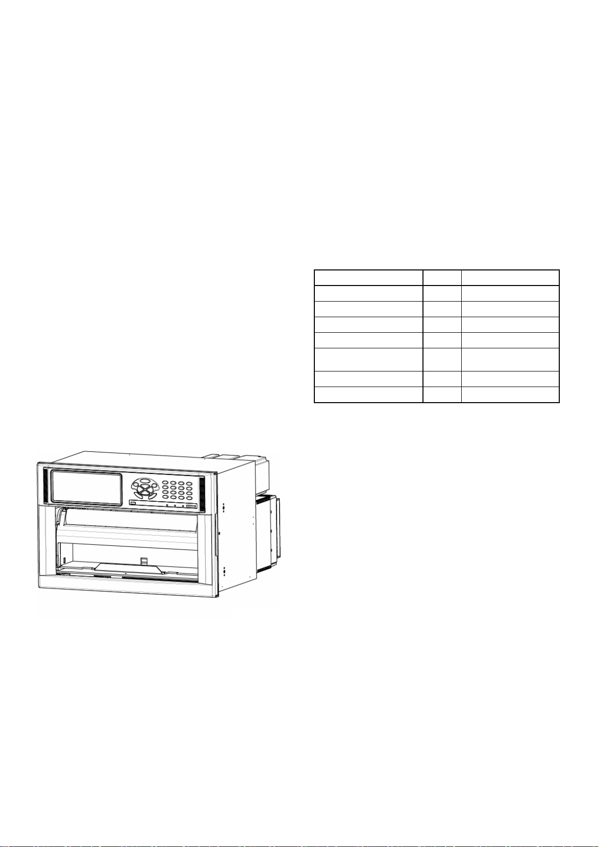
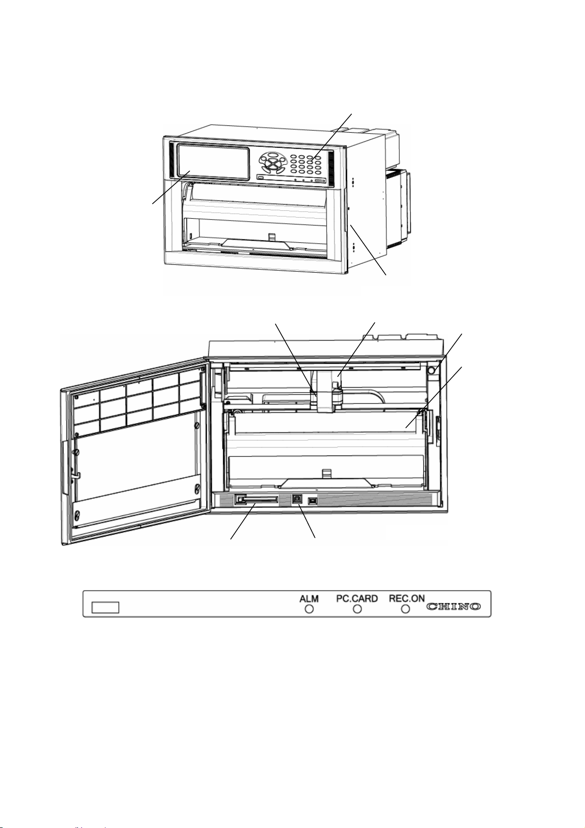
2-1 Front section
Operation and setting can be done without opening the door so that the front section is fully dust-proof.
Display
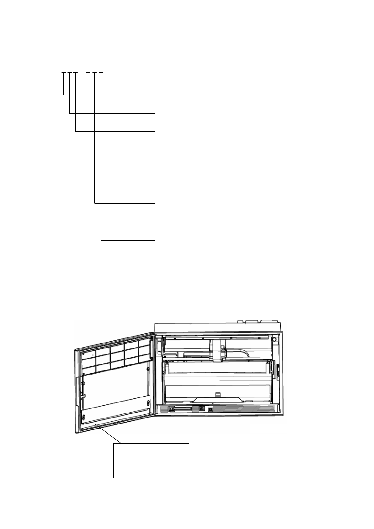
2-2 Front section of internal unit
Printer head Ink ribbon cassette
PC card insertion part USB communication connector
2-3 Display (status)
・ALM
Red LED flickers in the occurrence of an alarm.
・PC.CARD
Green LED remains lit when PC card is being inserted.
・REC.ON
Green LED lights when recording is turned on. Recording is turned on or off by REC key.
・CHINO
CHINO brand lights when power is turned on.
Operation and setting keys
Door grip
Power switch
Chart rack
2-1
Page 12
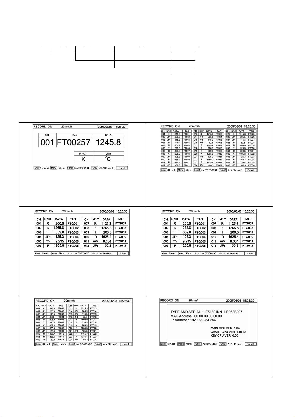
• Indications of the display section
Measuring data display
□□□ □□□ □□□□□□□ □□□□□□□□ :1Measuring data display by 1 channel
Channel display: 3 digits
Range display: 3 digits
Measuring data display 7 digits
Tag No. display: 8 digits or
Digits unit display 8
The following six screens are selectable according to the uses during run.
(Described update cycles show the initial setting values at the delivery time from the factory.)
1.
Measuring data are fixed or sequentially displayed every channel.
These data are updated to the next channel by ▲ or ▼ key.
The above keys can be used for sequentially display.
In the sequential display mode, measuring data are updated to the
next channel at 2-second cycle.
Also, measured values display is updated every second.
2.
Measuring data at 12 points are displayed collectively.
(In case of the instruments where No. of input points is 12 points.)
Skipped channels are kept blank. Each display area is not changed.
The same processing also applies to the channels where no range is
set. Measured values display is updated every second.
3.
Measuring data at 24 points are displayed collectively.
(In case of the instruments where No. of input points is 24 points).
Skipped channels are kept blank. Each display area is not changed.
The same processing also applies to the channels where no range is
set. Measured values display is updated every second.
4.
Measuring data at 36 points are displayed collectively.
(In case of the instruments where No. of input points is 36 points)
Skipped channels are kept blank. Each display area is not changed.
The same processing also applies to the channels where no range is
set. Measured values display is updated every second.
5.
Measuring data are fixed or sequentially displayed every 12 points.
(In case of the units where No. of input points is 24 points or 36 points).
These data are updated to the next 12 points by ▲ or ▼ key.
The above keys can be used for sequentially display.
In the sequential display mode, measuring data are updated to the
next 12 points at 3-second cycle.
Also, measured values display is updated every second.
6.
Type code, serial No., software version number, IP address, and MAC
address of this unit are displayed.
In all screens, various status, chart speed, date (year, month, day), and time are always displayed at the upper part
of the display, while various setting procedures are always displayed at the lower part of the display.
※ 5-digit display in case of collective
display of 36 points
2-2
Page 13
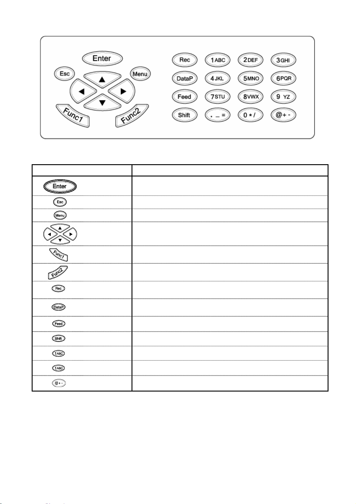
2-4 Keyboard
•
Names and functions of keys
Names of keys Functions
Enter key Enters various setting.
Escape key Returns the screen to the last one each time this key is pressed once.
Menu key Displays various setting items.
Up-Down,
Left-Right keys
Function key 1
Function key 2
Record key
Data print key
Feed key Feeds the chart at a speed of 750mm/min when this key is being pressed.
These keys are used to shift the cursor upward, downward, leftward, or
rightward. They are used for selecting setting items and numeric values.
Switches and sets various functions.
Displays the function at the lower part of display.
Switches and sets various functions.
Displays the function at the lower part of display.
Turns on or off recording.
This key is used together with Enter key.
Prints data momentarily when pressing this key.
This key is used together with Enter key.
Shift key Selects numeric keys and alphabetic or other symbolic keys.
Numeric key
Alphabetic key
Symbol key
Used for inputting a numeric value.
Used for inputting alphabetic characters (together with Shift key).
Used for inputting symbols (together with Shift key).
When alphabetic keys are used for setting the tag, unit, etc., press [Shift] key according to the guidance in the
display unit. The contents being input by pressing keys are switched by pressing [Shift] key.
Example) In case of inputting [C]
Switch the input mode of the key by pressing Shift key.
[C] can be input by pressing [1ABC] key 4 times.
2-3
Page 14
3. Mounting method
This unit can be used on a desk or the like, but it is constructed to be used by mounting it on a panel (instrument panel).
3-1 Selection of mounting place
3-1-1 Ambient temperature and humidity
Temperature range : 0 to 40℃
Humidity range : 20 to 80%RH
A stable place within the above ranges
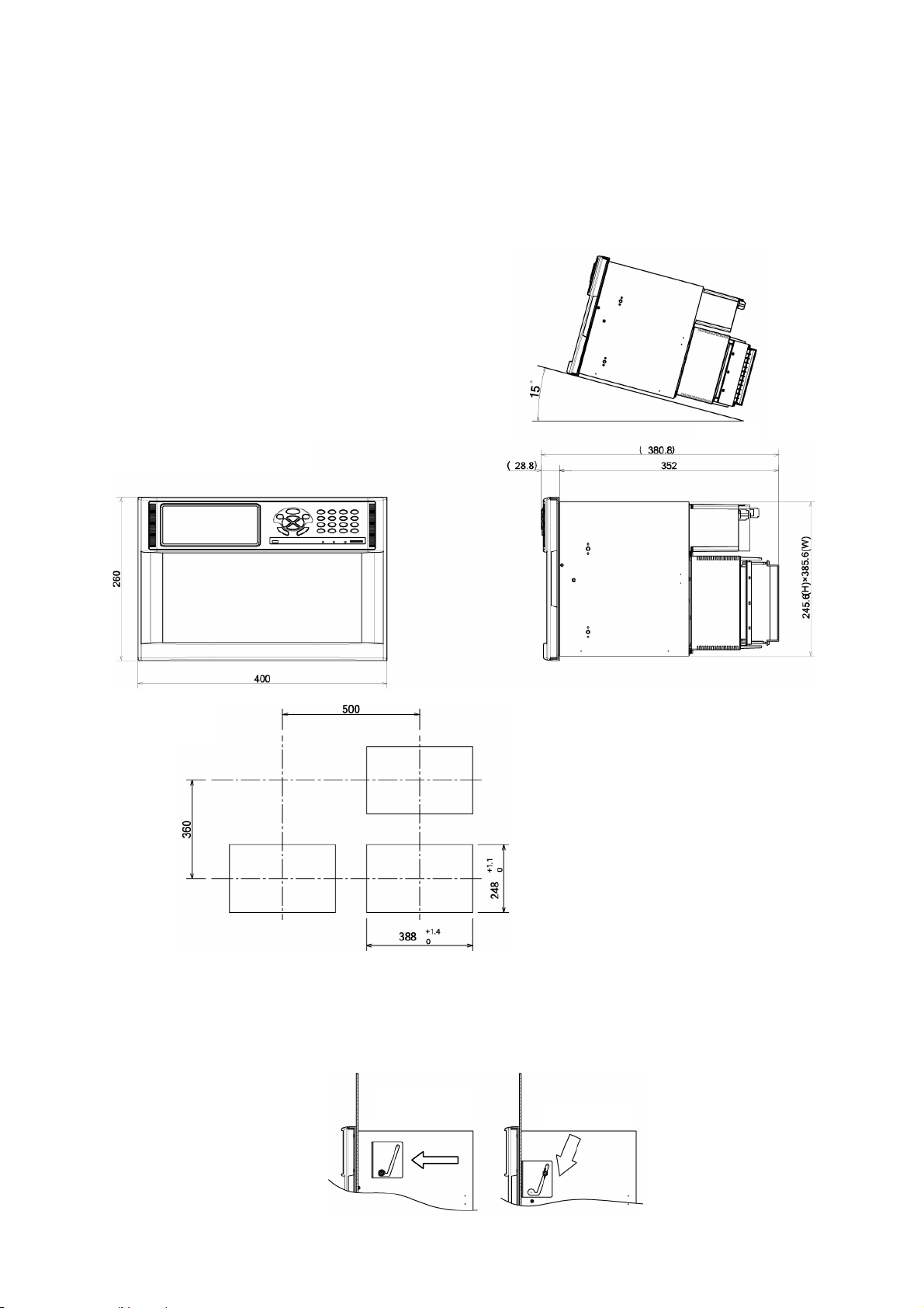
3-1-3 Mounting angle
Front tilting angle : 0°
Rear tilting angle : 0 to 15°
Lateral angle : 0°
A mounting angle other than specified above
may affect the recording operation.
3-1-2 Factory environment
Select a place being separated from electric
field and magnetic field generation sources and
also free of mechanical vibrations and shocks.
Overvoltage category :
Ⅱ
Pollution degree : 2
Altitude : Lower than 2000m
Working place : Indoors
3-2 Panel mounting method
3-2 Panel mounting method
3-2-1 External dimensions
3-2-1 External dimensions
3-2-2 Panel cutout
3-2-2 Panel cutout
Panel cutout and
Minimum mounting dimensions
3-2-3 Mounting method
Insert this unit into the panel cutout of the instrument panel. Screw in four attached mounting screws into the
screw holes at 2 upper and lower places (4 places in total) on the right and left side panels of the unit. Insert the
mounted hexagonal screw heads into the round holes of the mounting brackets, press the unit toward the
instrument panel securely from the front while sliding it as illustrated below, and fasten the screws by the attached
spanner or plus screwdriver under the above condition. Be careful since the mounting brackets differ from each
other on the right and left sides (Mount the unit by 2 persons)
Slide
3-1
Page 15
4. Connections
4-1 Cautions on connections
1. Feed source power supply
● For feeding power to the unit, use a single-phase power
source having the stable voltage without any distorted
waveform for the purpose of preventing wrong operation.
2. Separate the power supply from strong electric circuits
● Avoid connecting the input /output lines in the vicinity of
and/or in parallel with a drive power line or other strong
electric circuits. Separate the unit from them more than
50cm if the unit is in the vicinity of and/or in parallel with
them.
3. Separate the thermocouple input from a heat source
● Separate the terminals from a heat source (a heating
body) for reducing a reference junction compensation
error. Avoid the solar radiation or the like.
4. Separate the unit from a noise source
● Separate the unit from a noise source as far as possible,
otherwise an unexpected trouble may occur. Take a
noise-preventive measure, if the unit cannot be
separated form a noise source.
Major generation
sources
Countermeasure
5. Use crimp style terminals
① Attach crimp style terminals to the connection cord ends for
preventing terminals from being loosened or disconnected
or a short circuit failure across terminals.
② Use crimp style terminals each having an insulation sleeve
for preventing an electric shock accident.
6. Unused terminals
● Don’t use any unused terminal as a relaying terminal,
otherwise electric circuits may be damaged. For unused
terminals, short plus and minus terminals for preventing
the influences of external noises.
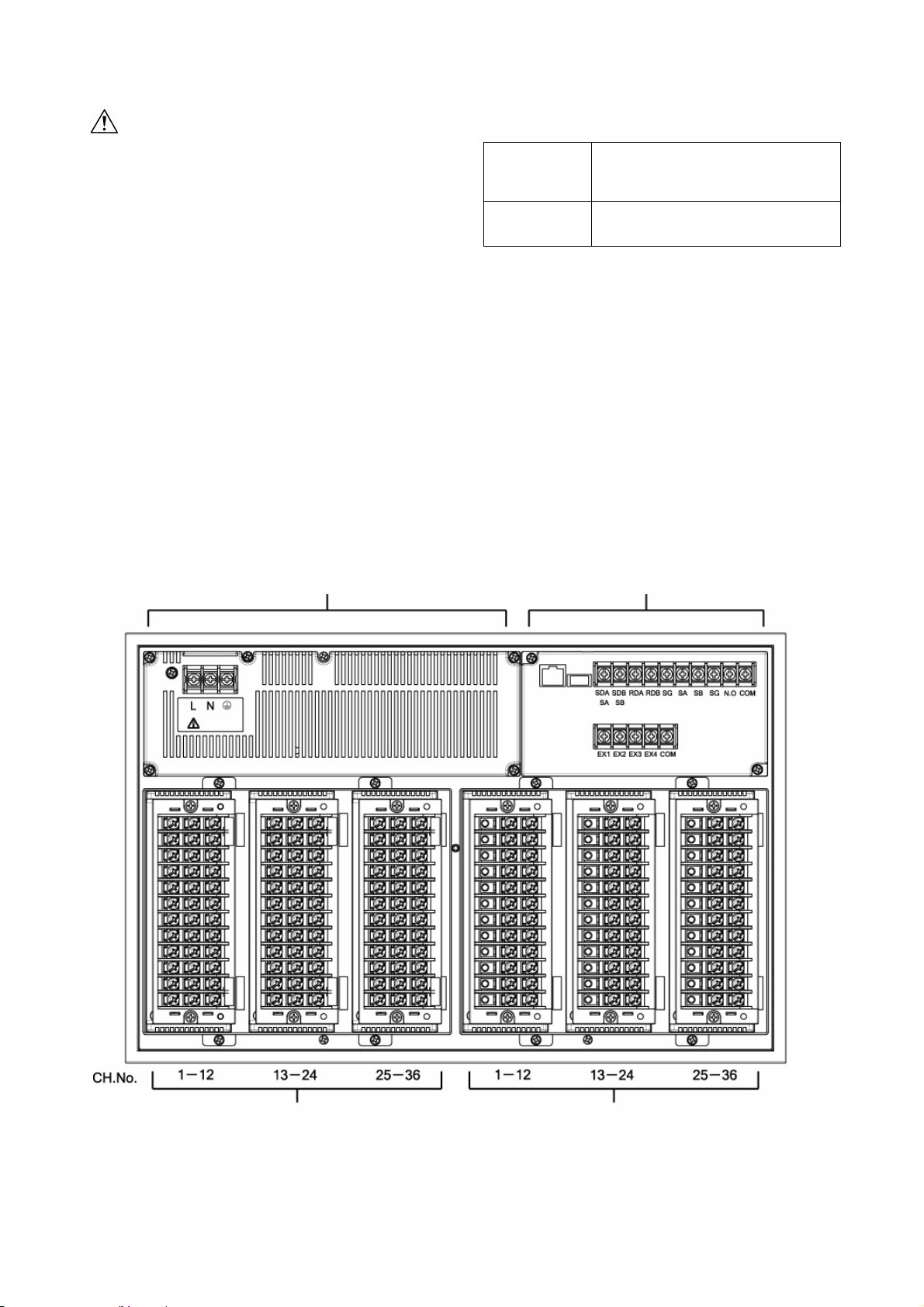
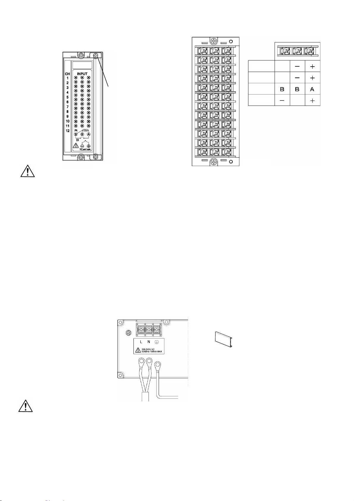
4-2 Terminal boards (rear panel)
The terminal boards are roughly divided into ① measuring input terminals, ② power terminals, ③ communication
I/F terminals, contact output terminals, external drive terminals, and ④ alarm output terminals. Terminals ③ and
④ are not always mounted depending upon the unit because of their option specifications.
②Power terminal board
①Measuring input terminal board
The above figure includes option terminals.
③ Communication I/F terminal, contact output terminal,
and external drive
④Alarm output terminal board
● An electromagnetic switch or the like
● A power line having waveform distortion
● An inverter
● A thyristor regulator
Insert a noise filter between the power
supply and input/output terminals.
A CR filter is used in many cases.
4-1
Page 16
4-3 Connections of each terminal board
g
4-3-1 Measuring input terminal board
Terminal cover mounting screw
(at 2 upper and lower places)
CH1
Volta
e
Thermo-
couple
Resistance
thermometer bulb
Contact
CH12
Cautions
1. Connect a voltage lower than the allowable input voltage to the input terminals.
① Voltage, thermocouple input --------- ±10VDC
② Resistance thermometer bulb ------- ±6VDC
2. Turn off the feed power source before starting connections for preventing an electric shock accident.
3. Mount crimp style terminals each having an insulation sleeve as input terminals.
4. For a DC voltage (current) input, use a twisted wire for instrumentation as a noise preventive measure. Connect a
current input receiving resistor to the channel to be measured before connecting the current input.
5. Connect the thermocouple input by using the thermocouple wire (or compensation lead wire) to the unit without fail.
If a copper wire is connected halfway, a noticeable error occurs. Don’t connect a part of thermocouple wires in
parallel with other instruments (a controller or the like), otherwise a trouble may occur.
6. For connecting the resistance thermometer bulb input, use a 3-conductor cord having an equal resistance value of
each conductor wire. Don’t connect a resistance thermometer bulb in parallel with any other instrument (a
controller or the like)
7. A high voltage may be applied to the measuring input terminals due to common mode noises. The allowable value
of noises is lower than 30VAC or 60VDC. Make sure that noises are lower than specified. After connecting
terminals, mount a terminal cover for preventing an electric shock accident and also protecting the input wires. In
case of the thermocouple input, a reference junction compensation error is reduced by mounting the terminal
cover.
4-3-2 Power terminals
Cautions
Power cable:
600V vinyl insulated wire
Crimp style terminal having an
insulation sleeve.
Note:
Use the following standard
cords ①-③.
①IEC 227-3
②ANSI/UL817
③CSA C22.2 No.21/4
Power terminal cover
Grounding wire:
Connect to the protective conductor of the power supply
equipment.
Crimp style terminal having an insulation sleeve
A copper cable each having a wire diameter of 2mm
Green/yellow
2
at least
1. Turn off the feed power source without fail before connecting the power terminals and protective conductor
terminals for the purpose of preventing an electric shock accident.
2. The power voltage of this unit is indicated at the power terminal block. If a voltage other than indicated should be
applied, a trouble or an operation failure occurs. If power noises are introduced, take a preventive measure by
connecting a noise cutting transformer to the ground or other preventive means.
3. A 100-240V AC voltage is applied to the power terminals after connections. Mount the power terminal cover
without fail after connections for preventing an electric shock accident.
4-2
Page 17
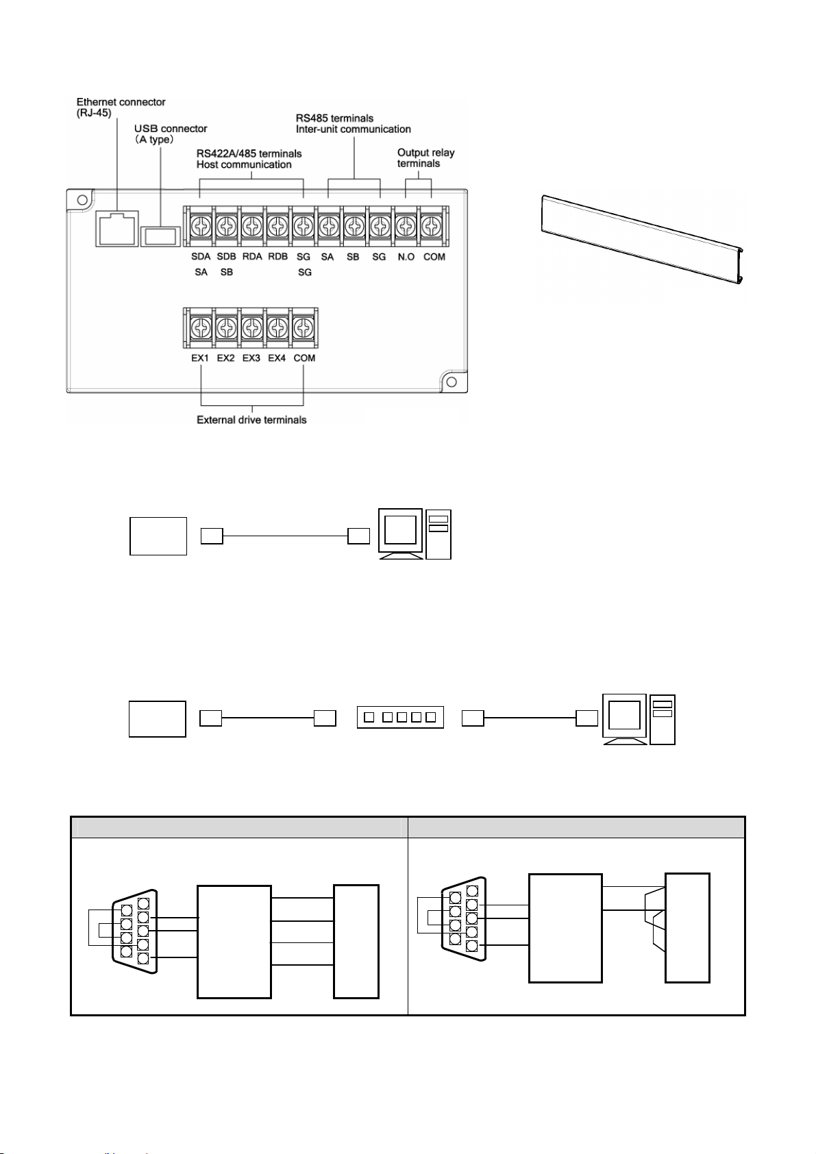
4-3-3 Communication I/F terminals, contact output terminals, and external drive terminals
g
g
resp
Output relay terminals Contact capacity 100V-240V AC
3V resistive load
Terminal cover
1. Ethernet connection (host communication)
[For connecting to PC at a ratio of 1 to 1]
Setting of alarm output and fail output such
as chart end and equipment abnormality
are available from output relay terminal.
Fail output is outputted in spite of not
setting, but in the case of outputting of
alarm, refer to 8-6 [Alarm setting], and set
[800] for output relay No..
For connecting the Ethernet IF to PC at a ratio of 1 to 1, use a cross type STP cable.
LE
STP cross cable
(
PC
A LAN function is attached)
[For connecting to PC at a ratio of N to N]
For connecting to plural PC units or existing LAN, use a switching hub, and connect a straight type STP cable
between the switching hub and the Ethernet unit.
LE
STP strai
ht cable
Hub
Twisted paired
strai
ht cable
A LAN function is attached)
(
PC
2. RS422A/RS485 terminal connections (host communication)
RS422A connection RS485 connection
PC side
9 pins connector
1
6
2
7
3
8
4
9
5
Line converter
SC8-10
RDA
SD
RDB
RD
SDA
SG
SDB
LE
SDA
SDB
RDA
RDB
SG
PC side
9 pins connector
1
6
2
7
3
8
4
9
5
For RS485, short SDA and RDA, and also, SDB and
RDB
Line converter
SC8-10
SD
RD
SG
ectively.
RDA
RDB
LE
SDA
SDB
RDA
RDB
SG
4-3
Page 18
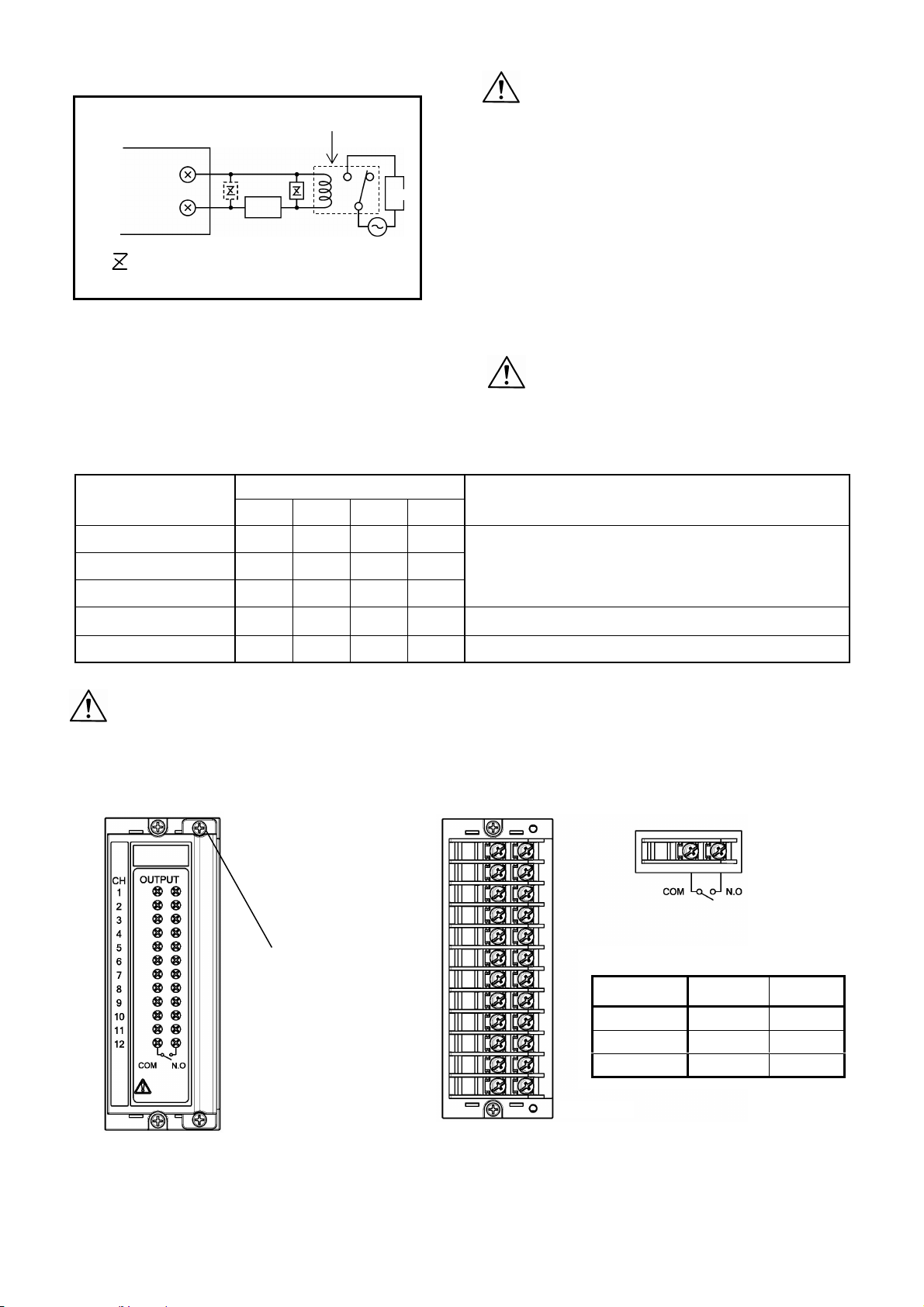
3. Output relay terminal connections
Power
supply
Buffer relay
a
Load
This unit
N.O
COM
b
: Contact protective device
(Mounting on “a” side is desirable)
4. External drive connections and operation selection
The following operation can be executed by contact
signals from the terminals.
① Selection of 3 chart speeds (speed numbers)
② Recording execution and stop
③ Data printing
External drive functions and inter-terminal conditions
External drive functions
Across COM – EX□ terminals
EX1 EX2 EX3 EX4
Cautions
1. Connect a load of less than the designated contact
capacity to the output relay terminals.
2. Turn off the feed power source and buffer relay
power supply before starting connections for
preventing an electric shock accident.
① Connect output relay terminals to the load via a
buffer relay.
② For connection to the output terminals, use crimp
style terminals each having an insulation sleeve.
3. The buffer relay power supply is applied to the
output relay terminals after connections and an
electric shock accident occurs if you should touch
these terminals. Mount a terminal cover without fail
after connections.
Cautions
Turn off the feed power source before starting
connections of external drive terminals for
preventing an electric shock accident.
Remarks
ON : Shorted
OFF : Open
Chart speed 1
Chart speed 2
Chart speed 3
Recording execution
and stop
Data printing
※)Data cannot be printed unless recording is being executed.
Cautions
OFF OFF OFF OFF
ON OFF OFF OFF
OFF ON OFF OFF
OFF OFF ON OFF
OFF OFF OFF ON
Receiving and feed operation by setting keys are effective.
For changing the selected chart speed number and chart
speed, refer to the instruction manual, option volume.
Receiving and feed operation by setting keys are ineffective.
Keep ON time for longer than 1 second.
For the contacts being connected to the external drive terminals, use contacts of a switch, a relay, or the like
which is driven by lower than 30V AC or 60V DC or use manual contacts.
4-3-4 Alarm output terminals
CH1
Terminal cover screw
(Remove two upper and
lower screws respectively)
CH12
Power supply
100VAC 0.5A 0.2A
メカリレー出力の接点容量
240VAC 0.2A 0.1A
30VDC 0.3A 0.1A
Resistive
load
(Caution 1) The alarm output is a mechanical relay “a” contact output. For connections, refer to
[3. Connections of output relay terminals].
Inductive
load
4-4
Page 19
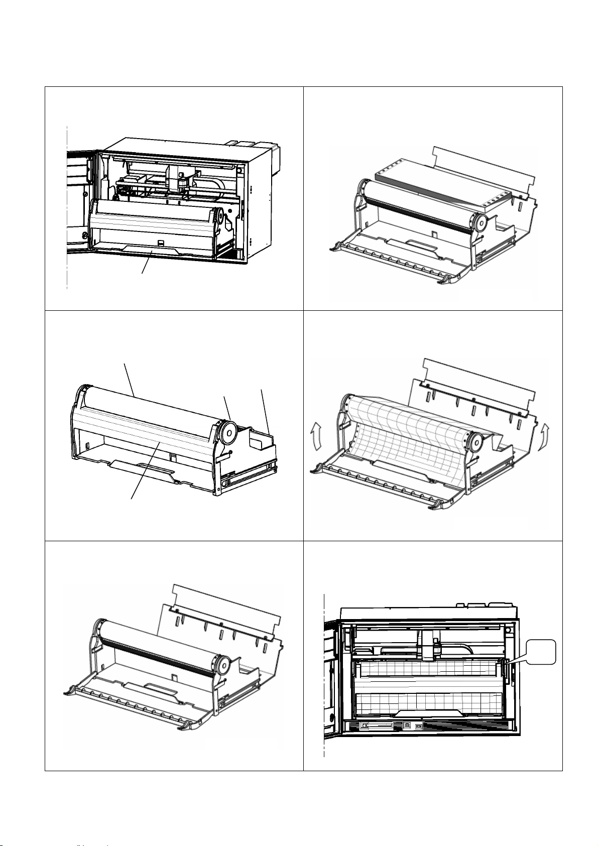
5. Installation of auxiliary products
5-1 Mounting method of chart
① After opening the door, take out the chart rack by pulling it
this side.
④ The chart is provided with circular holes at the left end and
elliptic holes at the right end. Put the chart into the chart
loading section horizontally under the condition.
※ Shuffle the chart sufficiently before setting the chart for
preventing a double feed.
Chart rack pull-out grip
② Chart rack unit
Chart drum
Front chart holder
③ Pull down the front chart holder and chart holder before
setting the chart.
Chart holder
Knob
⑤ Fit the holes at both ends of the chart to the chart drum
sprocket. After setting the chart, reset the front chart holder
and chart folder to their original positions from being tilted
down conditions in ③.
⑥ Mount the chart rack unit to the chassis, and fold the chart
by 2-3 by turning the knob by means of fingers. In this case,
set the chart fold to meet the convex and concave marks at
the right end of the chart.
Knob
5-1
Page 20
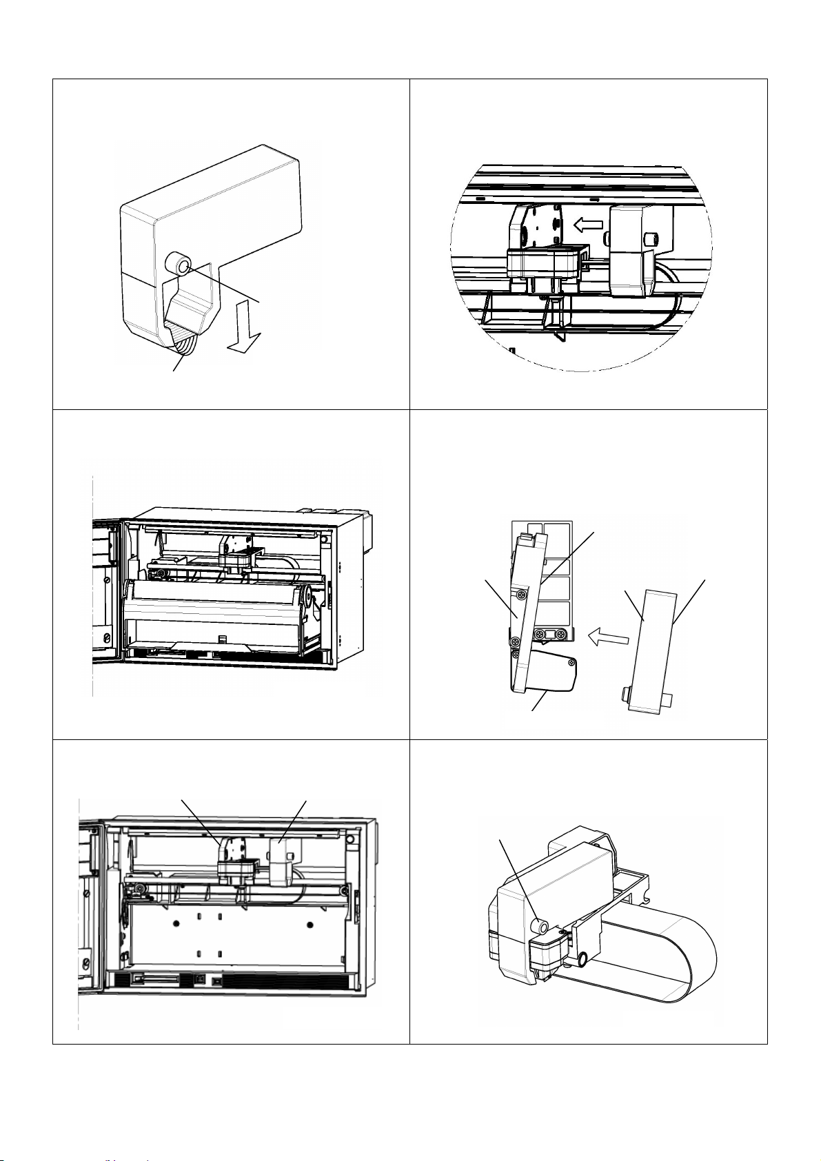
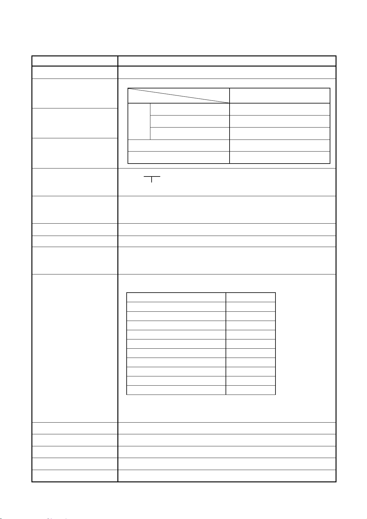
5-2 Ribbon cassette mounting method
① Prepare the ribbon cassette. Loosen the ribbon cassette
about 10mm by pressing it in the arrow direction using the
shaft of a ball-point pen or the like.
Ribbon knob
Ribbon
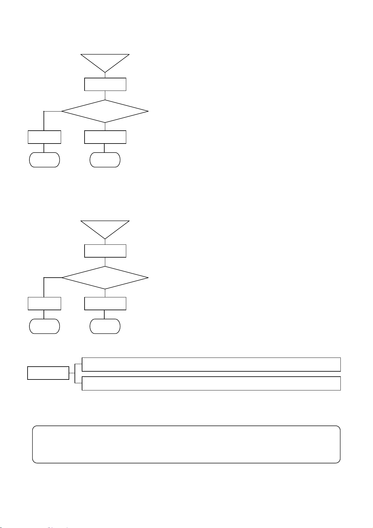
④ Keep the printer carriage unmovable by pressing it with
the left hand, and mount the ribbon cassette in the arrow
direction by the right hand.
② After opening the door, turn off the power switch and draw
out the chart.
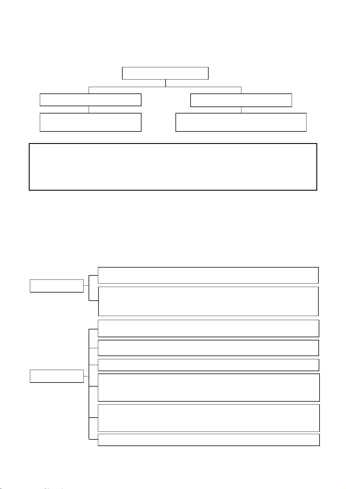
⑤ Refer to the top view shown below. The ribbon cassette is
mounted diagonally as illustrated below. Make sure that
face A of the printer carriage and face B of the ribbon
cassette are mounted without any clearance.
When the ribbon cassette is mounted completely, a click is
heard by the locker spring.
Printer carriage
Face A
Face B
Ribbon cassette
Printer head
③ Move the printer carriage to about the center by hand. ⑥ After the ribbon cassette has been mounted normally,
straighten the ribbon by turning the ribbon knob clockwise
Printer carriage Ribbon cassette
1-2 turns. Reset the chart rack unit to the chassis.
Ribbon knob
5-2
Page 21
6. Operation
6-1 Turning on the power supply
1) Confirm the connections.
2) After opening the door, turn on the power switch at the upper right of the chassis.
(Caution1 ) Setting information and clock are backed up. Also, the display mode is backed up, but the channel number is
Also, data are displayed by turning on the power supply again after turning it off once under the setting check
(Caution 2) If recording is turned off, a date (year, month, day) is not printed when turning on the power supply.
<Display>
— LE Series —
After about 5 seconds,
data are displayed.
not backed up. Accordingly, the range-set lowest channel number data are displayed in case of one-point
continuous display. In the same way, data are displayed starting with the range-set lowest channel number in
case of the multi-point sequential display.
condition.
(See caution 1)
6-2 Display mode selection
This unit provides 6 kinds of display modes, although this depending upon the number of input points.
1) Each measuring data is fixed and displayed every channel.
2) Each measuring data is sequentially displayed every channel.
3) All input points are displayed collectively. (12-point collective display in case of 12-point unit, 24-point collective display
in case of 24-point unit, 36-point collective display in case of 36-point unit)
4) 12-point measuring data are collectively fixed and displayed. (24-point and 36-point units excluding 12-point unit)
5) 12-point measuring data are collectively and sequentially displayed. (24-point and 36-point units excluding 12-point unit)
6) Type code, serial number, software version number of this unit are displayed.
Display update cycle
Display modes
Display update cycle of measuring data:
1 second
Display update cycle of input channels:
2 seconds (Setting of this factory delivery value can be changed.)
Collective display update cycle of 12 point data:
3 seconds (Setting of this factory delivery value can be changed.)
1-point fixed display mode: Fixed display of an optional channel.
Stepwise forward move by ▲ key and stepwise backward move by ▼ key
1-point sequential display mode: Input channels are displayed sequentially every 2 seconds.
Stepwise forward move by ▲ key and stepwise backward move by ▼ key
Collective display mode of all points.
12-point fixed display mode: Fixed display of 12 points.
Stepwise forward move by ▼ key and stepwise backward move by ▲key
Collective forward move of 12 points by ► key and collective backward move of
12 points by ◄ k e y
12-point sequential display mode: Sequential display of 12 points.
Stepwise forward move forward by ▼key and stepwise backward move by ▲key
Collective forward move of 12 points by ► key and collective backward move of
12 points by ◄ k e y
Power ON
<Printer>
Initial position detection
Date, time, chart speed, and [POWER ON ***]
are printed and the chart is fed about 3mm.
(See caution 2)
Model code, serial number, software version number display mode
6-1
Page 22
6-3 Recording operation
Start
y
y
y
y
y
y
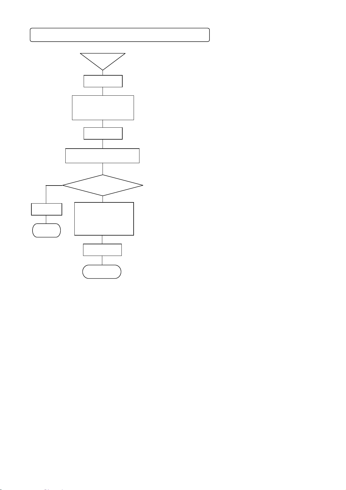
1) Recording ON-OFF
Recording can be turned on and off by Rec key and Enter key.
①
③
Esc ke
End
NO
Rec ke
Set?
YES
②
Enter ke
End
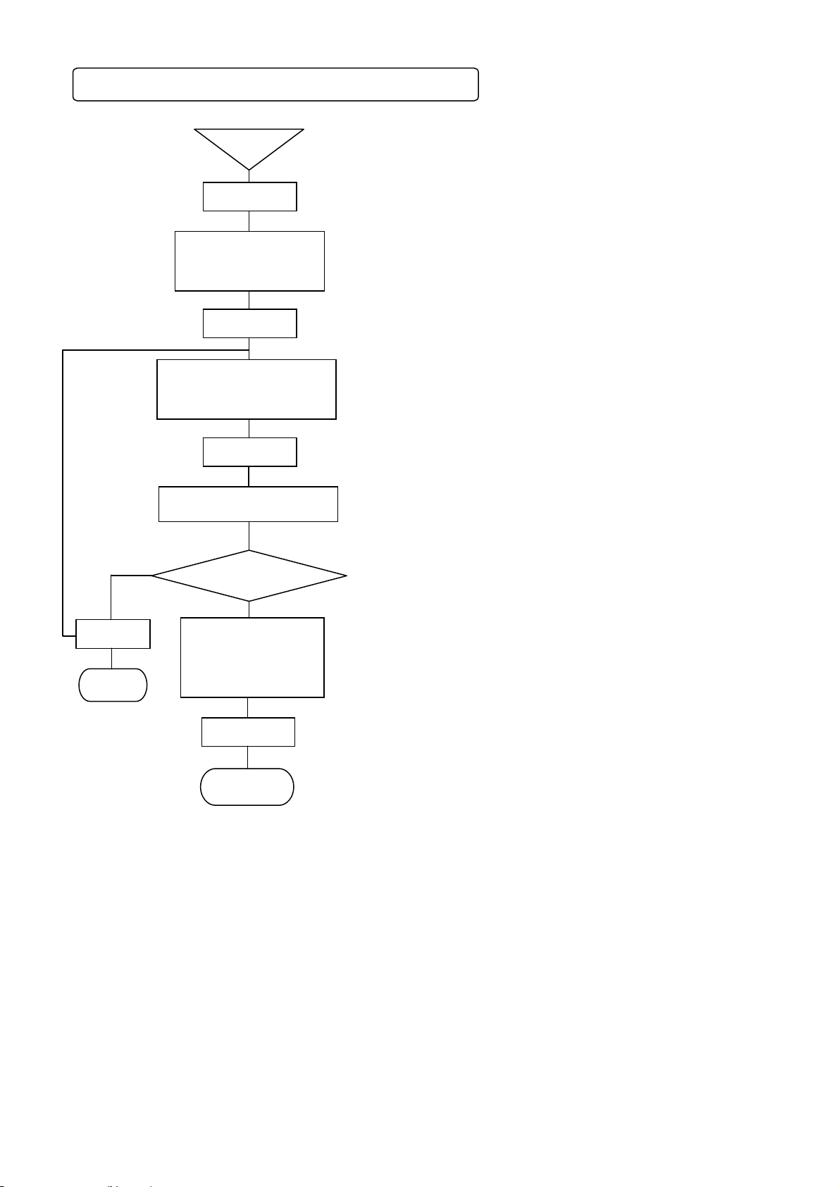
2) Data printing
Latest measuring data are digitally recorded by interrupting the present analog recording.
NO
Esc ke
End
②
Start
DataP ke
Set?
Enter ke
End
YES
①
③
① By pressing Rec key under Rec. ON condition, a message [Do
you terminate chart recording?] is displayed on the display unit.
By pressing Rec key under Rec. OFF condition, a message [Do
you start chart recording?] is displayed on the display unit.
② For stopping the setting, the screen returns to the last one, each
time Esc key is pressed once.
③ Terminate the setting by pressing Enter key. ON and OFF are
switched from each other by pressing Enter key.
(Caution 1)
REC. ON green LED lights in the status display unit under the
recording ON condition.
(Caution 2)
Recording is stopped under the recording OFF condition, but the
input entry, data update, and alarm, etc. operation are executed.
(Caution 3)
The following functions are not employable under the recording
OFF condition.
• Data printing • List printing
• Logging recording
① By pressing DataP key, a message [Do you start data printing ?]
is displayed on the display unit.
② For stopping the setting, the screen returns to the last one, each
time Esc key is pressed once.
③ Terminate the setting by pressing Enter key.
By pressing Enter key, the latest scan data at that time are
digitally recorded.
(Caution 1 )
Format is set by [DATA PRINT] of the menu.
(Caution 2 )
If digital recording is necessary at a fixed interval, use either data
interval recording or logging recording.
(Caution 3 )
Not employable under the recording OFF condition.
Two kinds of digital recording formats are available. These formats can be set optionally according to uses.
TAG+DATA+UNIT(10CH/1LINE) 10 channels/line (Max 11 digits per channel)
Format
TAG+DATA+UNIT(6CH/1LINE) 6 channels/line (Max 19 digits per channel)
3) Chart feed
The chart (recording paper) can be fed by Feed key.
The chart is fed at a speed of 750mm/min when Feed key is being pressed.
Use this function when measured objective and/or measuring conditions have been changed.
The chart can also be fed manually by the knob. However, it is possible that the chart is not fed by several
mm due to a mechanical reason of this unit. It is, therefore, recommended to feed the chart by Feed key.
Feed the chart by Feed key due to the same reason when a new chart has been mounted.
6-2
Page 23
7. Initial setting at the delivery time from the factory
r
7-1 Setting items at the delivery time from the factory
Items Initial setting items
(1) Time
(2) Range
(3) Scale
(4) Unit
(5) Tag number
(6) Skip
(7) Chart speed
(8) Scan cycle (Input entry cycle) Automatic development value of chart speed (28.8sec)
(9) Digital recording format
(10) Analog recording format
(11) Dots All OFF
Present time (year, month, day, Japanese time)
Item
① Input type V(-10.000 to 10.000)
(2)
Range
(3) Scale
(4) Unit
*01-*□□□
Channel numbe
①Display skip
②Digital printing skip
③Memory card recording skip
25mm/h Dotting cycle : Chart speed interlocking cycle
①Data interval (Data I)
②Logging recording
③Data printing (Data P)
①Format : Standard
②Recording colors
1・11・21・31・41・51・61・71
2・12・22・32・42・52・62・72
3・13・23・33・43・53・63
4・14・24・34・44・54・64
5・15・25・35・45・55・65
6・16・26・36・46・56・66
7・17・27・37・47・57・67
8・18・28・38・48・58・68
9・19・29・39・49・59・69
10・20・30・40・50・60・70
● Channels 37-72 are mounted as auxiliary channels.
They are used as differential recording channels, etc.
● Recording colors are those in initial setting and they can also be designated
optionally.
② RJ
③ Analog recording range -10.000 to 10.000
Channel numbers Recording colors
Models
Not provided ( external)
-10.000 to 10.000
① Model LE511 : *001-*012
② Model LE512 : *001-*024
③ Model LE513 : *001-*036
: Not set in all channels
: Not set in all channels
: Not set in all channels
: Not set
: Not set
: 1 line/6 channels printing
Green
Yellowish green
Orange
Red
Reddish purple
Brown
Bluish green
Purple
Bluish purple
Black
LE5100/LE5200
V
(12) Alarm setting Not set
(13) Differential recording setting Not set
(14) Message setting Not set
(15) Password setting
3571
7-1
Page 24
7-2 Mode change by soft switch
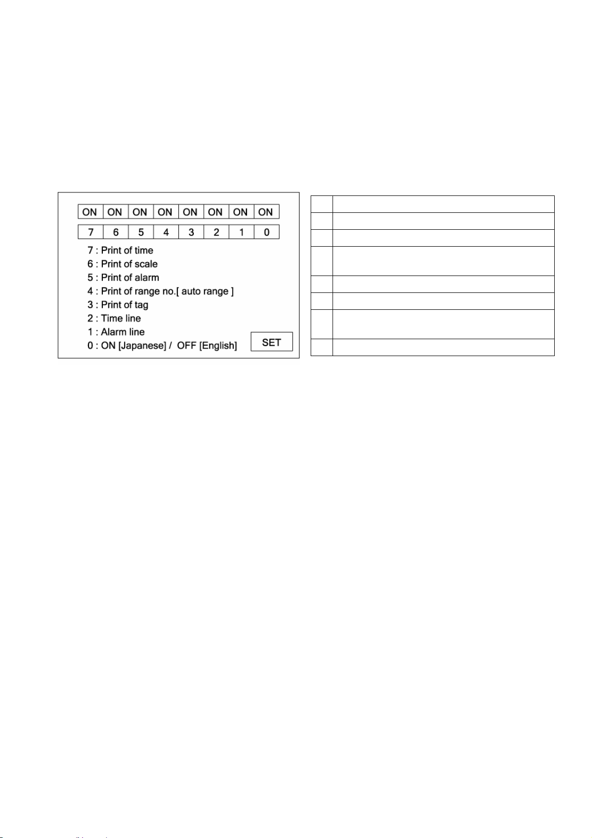
The LE5000 series is able to select ON/OFF (show/not show) of various printing by initial settings.
Refer to below for setting as required. Initial setting in factory delivery is all [ON].
1. Indication method of setting screen
When turn on the power supply of instrument, [LE Series] is displayed in the display screen. Enter [332] by setting
key of recorder while [LE Series] is displayed.
2. Detail setting
When enter [332], display a screen like below, so setup according to the following procedure.
When select [7] to [0] by key, and then press [enter] key, ON/OFF are switched every pressing [enter] key.
After every selects are done, cursor is moved to [SET] by key, and press [Enter] key to terminate the setting.
7
Time printing ON/OFF
6
Scale printing ON/OFF
5
Alarm activation/reset printing
Range No. printing ON/OFF at automatic range
4
switch
3
Tag printing ON/OFF
2
Time line printing ON/OFF
Alarm activation/cancellation mark printing
1
ON/OFF
0
Switch Japanese/English in setting screen
7-2
Page 25
8. Setting and changes by key operation
8-1 Basic rules
Read these rules without fail before starting setting
This paragraph describes general common items in setting operation.
1. Setting items and setting parameters
In measurement and recording, versatile recording results and data are obtained according to various
conditions setting of this unit.
Measuring and recording conditions such as the range, speed, chart speed, etc are called setting items.
Individual definite contents of these setting items are called setting parameters or merely parameters.
2. Calling of setting items
All calling is started with Menu key. By pressing Menu key, various setting items are displayed. Select a setting
item by ◄•►•▲•▼ keys and define it by Enter key. Certain setting items are displayed over several
hierarchies.
3. Calling of setting parameters
When the items to be set are defined, a window opens to be ready for setting the setting parameters.
4. Acceptance and acceptance failure of keys
If the cursor does not move by ◄•►•▲•▼ keys or the parameter setting window is not opened by Enter key, it
is caused by an acceptance failure. Check if these keys are pressed securely.
5. No. of parameters by setting items
Number of setting parameters depends upon the setting items. One parameter is provided for time and chart
speed, while several parameters requiring the designation of channels are provided for ranges, scales, and
alarms.
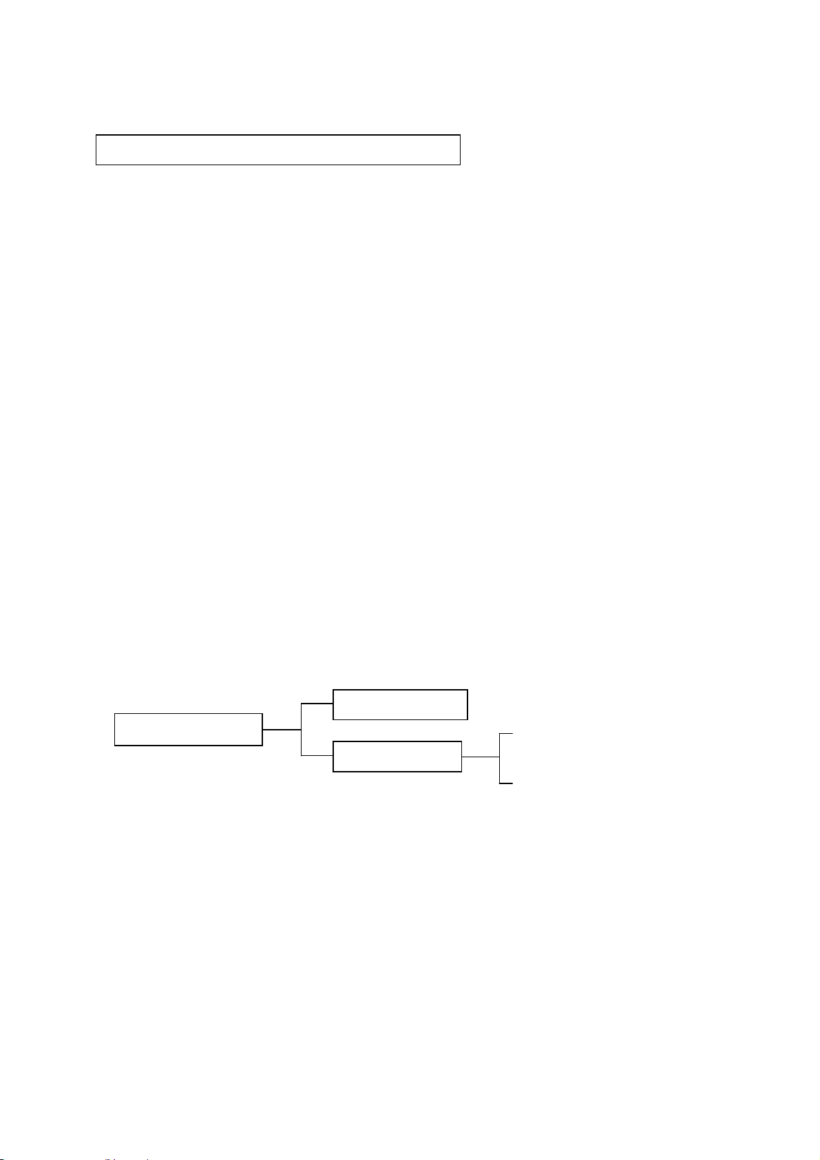
6. Confirmation of setting parameters
Setting parameters can be set in two ways. One is the list printing to confirm all setting items or designated
setting items by printing them, while the other is the display confirmation to confirm the setting parameters by
calling them to the display section. The [Display confirmation] method will be described here.
For the [List printing], refer to 8-9.
Setting parameter
confirmation
Display confirmation
All items list
List printing
Designated items list
When plural setting parameters are called, the preset lowest channel number is displayed.
After designating the channel number to be confirmed, press Enter key, and parameters of the channel are
displayed.
For confirming the other channel, return to the last screen by Esc key, select the channel by ◄•►•▲•▼ keys,
and press Enter key again to display the parameters of the channel.
If setting (change, addition) is not executed, irrespective of the number of setting parameters, press Esc key,
and the screen returns to the last one. Continue pressing Esc key until the mode returns to the normal display
mode.
8-1
Page 26
Start
y
y
y
1. Confirmation method in case of one setting parameter
◄•►
①
②
③
⑤
Esc ke
End
NO
Menu ke
Selection of setting items
by
◄•►•▲•▼ keys
Enter ke
Setting parameter display
④
Setting (change,
addition) by using
•▲•▼ keys, numeric
keys, etc.
Set?
YES
① Select the setting display mode by pressing Menu key.
A window opens to display a list of setting items.
② Move the cursor by ◄•►•▲•▼ keys and select an item to
be confirmed.
③ Select the setting mode of the desired setting item by
pressing Enter key.
A window opens to display various setting parameters.
④ If setting (change or addition) is not done after confirming
various setting parameters, return to the last screen by
pressing Esc key.
In case of the left procedure example, the screen is reset
to the start screen by pressing Esc key twice.
⑤ If setting (change or addition) is done after confirming
various setting parameters, use ◄•►•▲•▼ keys and
numeric keys.
⑥ Press Enter key to terminate the setting (change, addition).
Enter key
Setting end
⑥
8-2
Page 27
y
y
y
y
2. Confirmation method in case of plural setting parameters
Selection of setting items
by ◄•►•▲•▼ keys
Selection of channel number
by
Setting parameter display
NO
Esc ke
⑥
addition) by using
•▲•▼
End
Start
Menu ke
Enter ke
◄•►•▲•▼keys
Enter ke
Setting (change,
Set?
YES
◄•►
keys, numeric
keys, etc.
①
②
③
④
⑤
⑦
① Select the setting display mode by pressing Menu key.
A window opens to display a list of setting items.
② Move the cursor by ◄•►•▲•▼ keys and select an item to
be confirmed.
③ Select the setting mode of the desired setting item by
pressing Enter key.
A window opens to display channel numbers.
④ Move the cursor by ◄•►•▲•▼ keys and select a channel
to be confirmed.
⑤ Select the setting mode of the desired setting item by
pressing Enter key.
A window opens to display various setting parameters.
⑥ For advancing the channel forward or backward after
confirming the setting parameters of the channel to be
confirmed, press Esc key to return to the last screen, and
repeat steps ④-⑥.
Press Esc key if setting (change, addition) is not done.
In case of the left procedure example, the screen is reset
to the start screen by pressing Esc key twice.
⑦ If setting (change or addition) is done after confirming
various setting parameters, use ◄•►•▲•▼ keys and
numeric keys.
⑧ Press Enter key to terminate the setting (change, addition).
Enter key
Setting end
⑧
8-3
Page 28

7. Setting change
For setting change, shift the cursor to a desired point to be changed.
For moving the selection system parameters by cursor, ▲•▼ keys are used. However, ◄•► key is
normally used. Setting can be changed by the substitution method, edition method by shifting the cursor,
and new setting method after erasing all setting.
Setting change
Substitution method
Edition method
New setting method
Change or erase by moving the cursor to the position to be changed
Edition by moving the cursor to the position to be changed
New key input after erasing all setting
1) Substitution method
Select a setting parameter to be changed. The selected setting parameter is high-lighted like 150 .
Input the parameter by keys directly after the selected setting parameter has been high-lighted as shown in
the example.
2) Edition method
Select a setting parameter to be changed. The selected setting parameter is high-lighted like 150 .
Press ◄•► key after the selected setting parameter has been high-lighted as shown in the example.
The high-lighting is reset and
150l cursor is displayed.
Edit the parameter by shifting the displayed cursor using ◄•► key.
By pressing Esc key under the 150l condition, 150l returns to 150 .
▲ key serves as the back space key while ▼ key serves as the delete key in this edition mode.
3) New setting method
Select a setting parameter to be changed. The selected setting parameter is high-lighted like 150 .
Erase the setting parameter by using ▲ key (back space key) or ▼ key (delete key) after the selected
setting parameter has been high-lighted as shown in the example. Then, input new parameter directly.
8. Switching of keys
When alphabetic keys or symbol keys are used, switch them by pressing [Shift] key.
This switching can be done only when alphabetic or symbol keys are necessary for [Units], [Tags],
[Messages], etc.
(Example: Setting of message printing)
By pressing [Enter] key after bringing the
cursor to the message, Shift : numeric
characters/alphanumeric characters are
displayed at the lower part of the display.
If [1] is high-lighted, numeric keys only
can be input. When [Shift] is pressed, [A]
is high-lighted to be ready for inputting
alphanumeric characters.
When [A] is high-lighted, [1 ABC] key is
switched in the order of 1 → A → B → C
→ a → b → c → 1.
9. Setting change mark
When a setting parameter is entered, a setting change mark is printed at the right end of the chart.
A changed item is printed on the right side of [<] as a setting mark.
For changing each channel, [<S] is printed in case of [<C] system (chart speed, etc.).
10. Setting define function
By pressing Enter key, the setting contents are checked by the unit. If an error occurs when checking the
setting contents, the status part at the lower part of the display turns red, and the error contents are
displayed.
8-4
Page 29

11. Basic entry of setting parameters
When various setting parameters are entered, a window opens to display a setting parameter entry screen.
The basic common operation in the setting parameter entry screen is as shown below.
Example 1: Chart recording setting screen; In case of selection of setting parameters by ▲・▼ keys.
1. ①, ③, ⑤, and ⑦ are called a setting item ,while ②, ④,
and ⑥ are called a parameter input area.
2. When the setting parameter entry screen is displayed,
chart speed ① is high-lighted (A cursor is present on the
chart speed). Set the cursor to meet the dot
synchronization by ▲・▼・◄・► keys under the above
condition.
Press Enter key. Parameter input area ④ is high-lighted to
be ready for selection (input).
3. A window as shown in ⑧ is displayed when selecting
setting parameters as shown in this example. Select a
setting parameter by using ▲・▼ keys in this window.
For setting the chart speed, bring the cursor to meet the
chart speed by ▲・▼ keys and press Enter key.
4. By pressing Enter key after setting the parameter input
area ④, optional cycle ⑤ is high-lighted. By pressing
Enter key under this condition, parameter input area ⑥
is high-lighted to be ready for input.
5. By pressing Enter key after parameter input area ⑥ has
been set, define ⑦ is high-lighted. When no error occurs
in setting parameters of all setting items, press Enter key,
and the setting ends.
If a setting item is in error to move to the other setting
item, press ▲・▼ keys, and the move can be done to each
setting item on condition that Enter key is not pressed yet.
(Point 1)
When the cursor is present on a setting item, the setting
item can move to individual setting items by ▲・▼・◄・
► keys.
8-5
Page 30

Example 2: Display mode setting screen; In case of inputting a setting parameter by using keys
1. When the setting parameter entry screen is displayed,
AD ① is high-lighted. (The cursor is present on AD)
By pressing Enter key under this condition, parameter
input area ② is high-lighted to be ready for input.
2. Input a setting parameter by numeric keys, etc. under
the high-lighted condition of parameter input area ②.
Cursor [ | ] in the parameter input area can be moved
by ◄・► key under this condition. Press Enter key
after the end of input.
3. By pressing Enter key after setting the parameter input
area ②, month ③ is high-lighted.
By pressing Enter key after parameter input area ⑫
has been set in the same way, define ⑬ is high-lighted.
When no error occurs in setting parameters of all setting
items, press Enter key, and the setting ends.
If a setting item is in error to move to the other setting
item, press ▲・▼ keys, and the move can be done to
each setting item on condition that Enter key is not
pressed yet.
(Point 1)
When the cursor is present on a setting item, the setting
item can move to individual setting items by
► keys.
(Point 2)
By pressing ◄ key or ► key when the parameter input
area is high-lighted, cursor [ | ] is displayed in the
parameter input area to be ready for moving by◄・►
key.
(Point 3)
When cursor [ | ] is displayed in the parameter input
area to be ready for moving by◄・►key, ▲key serves
as Back Space key, while ▼ key serves as Delete key.
(This is not applicable if the parameter input area
adopts the selection method.)
▲・▼・◄・
8-6
Page 31

8-2 Display setting
y
y
y
This unit comprises 4 kinds of display modes. The present display mode is [12CH], but the other display mode is
settable as occasion demands.
Esc ke
End
NO
Selection of setting items
by
⑤
Start
Menu ke
◄•►•▲•▼ keys
1CH・12CH・
Set?
YES
Enter ke
Setting end
①
④
(Caution 1)
If skip is designated, data in skip designation
channels are not displayed.
(Caution 2)
The update cycle of data display is 1 second,
and the input loading cycle is 0.1 second
fixation. The data update cycle and the input
loading cycle are not synchronized.
(Caution 3)
Channels can be moved forward or backward
by ◄•►•▲•▼ keys even in case of the
sequential display mode.
(Caution 4)
By turning off the power supply, the one-point
fixed display mode is held, but the data
display channel number is reset to the lowest
channel number in range setting.
③
① Select the setting display mode by pressing Menu key.
A window opens to display a setting items table.
② Move the cursor by ◄•►•▲•▼ keys and select an item to be
confirmed.
③ Select 1CH, 12CH, or 36CH.
④ After selection, the desired display mode to be set is defined.
Either fixed display or sequential display is selectable in each
②
display mode.
(AUTO: Sequential/CONST: Fixed are switched from each
other, each time Func1 key is pressed once.)
⑤ For stopping the setting, the screen returns to the last one,
each time Esc key is pressed once.
A list of the kinds of display
11CH
2 1CH
3 12CH
4 12CH
5 1・12・36CH
6 1・12・36CH
1-point fixed display
1-point sequential display
12-point fixed display
12-point sequential display
All-point fixed display
All-point sequential display
Display mode
Tag
Unit
For details, refer to 8-13 [Display].
Channel number + Range + Measuring data + Tag
Channel number + Range + Measuring data + Unit
※) If 1CH display is set, the display mode is limited to one
kind of [Channel number + Tag + Measuring data +
Range + Unit].
※) If SYS.DISP is set, system information about this
instrument is displayed. For details of display, refer to page
2-2.
8-7
Page 32

8-3 Channel parameter setting [CH PARAM.]
Start
y
y
y
y
y
Range, RJ (internal/external switching of reference junction temperature compensation), scale, unit, etc. of each
channel can be set collectively every channel.
NO
Esc ke
End
NO
Selection of setting items
◄•►•▲•▼ keys
by
CH PARAM.
Setting table display
(Collective setting of 12 points)
⑤
Select a channel by
using
Setting parameter display
Setting (change, addi-
tion) by using
item by◄•►•▲•▼
keys, numeric keys, etc.
Do you continue
Setting end
Menu ke
Enter key
Set?
YES
▲・▼ keys.
Enter ke
Set?
YES
setting
Enter ke
setting?
Esc ke
NO
①
③
④
⑦
YES
⑨
① Select the setting display mode by pressing Menu key.
A window opens to display a setting items table.
② Move the cursor by ◄•►•▲•▼ keys and select an item to be
confirmed.
③ Select CH PARAM.
④ Press Enter key to enter the setting table display. (For the setting
table display (collective 12 points) screen, refer to ⑥.)
⑤ For stopping the setting, the screen returns to the last one each
②
time Esc key is pressed once.
⑥ Move the cursor to a desired channel number to be set by ▲•▼
keys. The cursor does not move to any item other than CH No.
⑦ Select a channel to be set and press Enter key.
⑥
A window opens to display a setting parameter entry screen.
(For the setting parameter entry screen, refer to ⑧.)
⑧ Move the cursor to a desired item to be set by ◄•►•▲•▼ keys.
The cursor moves in the sequence of Input → RJ → Burn →
⑧
Filter → Range MIN → Range MAX → Scale MIN → Scale
MAX → Correction → Unit → Lower-limit of chart recording →
Higher-limit of chart recording → Tag → Display skip → Digital
printing skip → Memory card recording skip → Set, each time
Enter key is pressed once.
CH No. is fixed to the channel number selected in the setting
table display (collective 12 points) screen. For the parameter
input areas for input, RJ, burn, filter and various skips, setting
parameters are selected. Select them by ▲・▼ keys after the
window has opened. For the MIN and MAX of Range,
correction, MIN and MAX of scale, and MIN and MAX of chart
recording, input their setting parameters by using numeric
keys. For the unit and tag, input their setting parameters by
using numeric keys or other keys.
After the end of setting in this screen, bring the cursor to
Set .
⑨ Terminate the setting (change, addition) by pressing Enter key.
Press Esc key if the setting contents are not saved.
8-8
Page 33

⑩ By pressing Func1 in the screen display in ⑥ above,
r
the following screen is displayed. Screens ⑥, ⑩
are used for confirming the setting and copying the
setting items in the setting screen to the other
channels.
For returning to screen ⑥ from screen ⑩, press
Func1 key again.
Screen ⑧ can also be displayed by pressing Enter
key after moving the cursor to a desired channel
number to be set by ▲•▼ keys in this screen.
⑪ For copying channel parameters to the other
channel, press Func2 key in either screen ⑥ or ⑩.
⑫ Move the cursor to a desired item to be copied by ◄
•►•▲•▼ keys.
Each time Enter key is pressed once, [レ]/[ ] is
repeated.
Select [レ] for a desired setting item to be copied, and
select [ ] for a setting item to be not copied.
Press Enter key after moving the cursor to the copy
source.
After inputting a desired channel number as the copy
source by numeric keys, press Enter key, and the
cursor moves to the copy destination. By pressing
Enter key furthermore, the channel number at the
copy destination can be input by numeric keys.
By pressing Enter key after inputting a channel
number at the copy destination, the cursor moves to
[~]. Press Enter key, and the channel number at the
copy destination can be input by numeric keys.
After the end of setting on this screen, bring the
cursor to Copy
.
⑬ Terminate the copy by pressing Enter key.
※)When the input kind, scale lower-limit, and scale
higher-limit are changed in the setting of a channel
parameter, other settings (set value, dead band etc.)
may be influenced.
※)Resolution of analog recording depend on setting
value of scale lower-limit/higher-limit, not depend on
setting of chart recording lower-limit/higher-limit.
[Points] Channel parameter setting short-cut
Items ①-⑥ on the last page can be short cut so long as
the channel parameter setting is concerned. Bring the
cursor to a desired channel to be set by ◄•►•▲•▼
keys in each display mode of one-point display, 12-point
collective display, or all-point collective display, and then,
press Enter key.
Screen ⑧ on the last page is displayed and the setting
can be done by the same operation.
1. In case of one-point display, no cursor is displayed, but
the channel in which Enter key was pressed can be set.
2. In 12-point collective display/all-point collective display,
the cursor is present on a channel number. Move the
cursor by pressing ◄•►•▲•▼ keys.
3. When the channel parameter setting short-cut was used,
no copy function is provided on the setting screen.
4.For setting [℃], bring the cursor to the unit, and press
the Enter key for enabling the parameter input. [Shift] is
displayed below the setting screen (refer to page 8-4: 8.
Switching of keys). Press the shift key and high-light [A],
and press the key of right next shift key 4 times. Then,
input C and press Enter key for termination setting unit.
[Setting example]
Setting relation of [Scale lower-limit], [Scale higher-limit],
[Chart recording lower-limit] and [Chart recording higherlimit].
• Use K (-200.0 to 500.0) for input.
• Set [Scale lower-limit] to -200.0.
• Set [Scale higher-limit] to 500.0.
• Set [Chart recording lower-limit] to -100.0.
• Set [Chart recording higher-limit] to 300.0.
The recording range is reflected by each setting as
shown in the following figure.
Scale lower-limit Scale higher-limit
Scale zero
Chart recording
lowe
-limit
Scale span
Chart recording
higher-limit
Recording zero Recording span
(Caution 1)
Range lower-limit and higher-limit, scale higher-limit and
lower-limit, and chart recording lower-limit and higher-limit
can be set up to max. 5 digits (or can be set up to max. 6
digits if minus [-] is included).
If a numeric value includes a decimal point, however, the
numeric value excluding the decimal point is limited up
to ±30000.
Example: Settable up to ±300.00
If 500.00 is set, a message [The input value is
abnormal] is displayed and the setting is not
acceptable. Units and tags can be set up to max. 8
digits.
(Caution 2)
For moving between channels, use ▲・▼ keys.
In the channel parameter setting mode, channels 1-12
are displayed. For moving to channels 13-24, move the
cursor to channel 12, and press ▼ key. For moving to
channels 1-12 under the displayed condition of channels
13-24, on the contrary, press ▲ key.
8-9
Page 34

1.Operation recording
Operating conditions of peripheral units or the like are recorded at an optional position of the chart as operation
recording. This function is provided as a relative recording function between system conditions and measuring
data.
Max. 36 records can be marked on the chart.
Contact input Data display Digital recording Analog recording
Communication
output
Open
Short
【Note】 When the parallel scale recording of recording format is used, the recording positions
are % to the span of each area
OFF OFF
ON ON
Designated position (range setting)
2% (5mm) to the span (right) direction
The chart recording lower-limit is set to
[50] and the higher-limit is set to [52] at
the delivery time from our factory as
recording positions. By setting the chart
recording lower-limit to an optional
value, its set value +2 is automatically
expanded as the higher-limit.
Since the recording width can be
changed optionally, the chart recording
higher-limit value can be set optionally
in the same way as in the lower-limit.
If the chart recording higher-limit value
is smaller than the lower-limit value
ON/OFF recording positions are
reversed.
0
1
【Setting method】
1)This operation is done by setting channel parameters. (Ⅰ. Instruction Manual 8-2 [CH. PARAM.] )
2)For input, select ON/OFF (1:ON / 0:OFF).
Settable items are input chart recording lower-limit / higher-limit, unit, tag, display skip, digital printing skip,
and memory card recording skip only. The cursor also moves to the other items, but no setting can be done.
3)Set the OFF recording position in units of % (every % step).
Set the ZERO side of the chart to 0% and the SPAN side to 100%. For this setting, input them to the chart
recording lower-limit / higher-limit setting parameter input area by numeric keys. The settable recording
position range is 0 to 99%. (The higher-limit is MAX. 100%)
4)Unit, tag, and skip can be set in the same way as in normal input.
【Input connection】
CH1
CH12
ABB
8-10
Page 35

2.Data communication input
The “data communication input” is the function that records and calculates the data concurrently with measuring
data which is sent from the host via the communication interface.
【Setting method】
1)This operation is done by setting channel parameters. (Ⅰ. Instruction Manual 8-2 [CH. Param.])
2)For input, select “COMM”.
Settable items are input, chart recording lower-limit/higher-limit, unit, tag, display skip, digital printing skip, and
memory card recording skip only. The cursor moves to the other items, but no setting can be done.
3)Change the setting of recording range.
Lower-limit “-3000.0”, higher-limit “3000.0” are already set in setting parameter input area of chart recording
lower-limit/higher-limit. Change the setting value (include decimal point position) depending on the
communication input value.
4)Unit, tag, and skip can be set in the same way as in normal input.
【Note 1】
Setting of data communication input is made form channel 1 to channel 36.
【Note 2】
If data communication input is not received, recording (analog/digital) is not performed even if setting of channel
parameter is done.
8-11
Page 36

8-4 Dot setting [DOT]
y
y
y
y
g
Tags and dot colors can be set every channel. Ten dot colors can be set optionally every channel.
NO
Esc ke
End
NO
Selection of setting items
by
Setting table display
(Collective setting of 36 points)
⑤
Select dot No. by using
Setting parameter display
Setting (change, addi-
tion) by using
item by◄•►•▲•▼
keys, numeric keys, etc.
Start
Menu ke
◄•►•▲•▼ keys
DOT
Enter key
Set?
YES
◄•►•▲•▼
Enter key
keys
Set?
YES
setting
Enter ke
Do you con-
tinue settin
Esc ke
Setting end
?
NO
①
③
④
⑦
YES
⑨
① Select the setting display mode by pressing Menu key.
A window opens to display a setting items table.
② Move the cursor by ◄•►•▲•▼ keys and select an item to be
confirmed.
③ Select DOT.
④ Press Enter key to enter the setting table display (collective 36
points) screen. [For the setting table display (collective 36
points) screen, refer to ⑥.]
②
⑤ For stopping the setting, the screen returns to the last one, each
time Esc key is pressed once.
⑥ Move the cursor to a desired dot number to be set by ◄•►•▲•▼
keys. The cursor does not move to any item other than dot No.
⑦ Select a dot No. to be set and press Enter key.
⑥
A window opens to display a setting parameter entry screen.
(For the setting parameter entry screen, refer to ⑧.)
⑧ Move the cursor to a desired item to be set by ◄•►•▲•▼ keys.
The cursor moves in the sequence of Input channel → Tag →
⑧
Color → Record → Set, each time Enter key is pressed once.
Use numeric keys for input channel or use numeric keys or
other keys for tags, and input setting parameters to the
parameter input area. For other parameter input area, select
setting parameters. A window opens to be ready for selection
by ▲・▼ keys. After the end of setting in this screen, bring the
cursor to Set .
⑨ Terminate the setting (change, addition) by pressing Enter key.
Press Esc key if the setting contents are not saved.
(Caution 1)
Default *001, *002 … are input (displayed) in the tag area on
screen ⑥. No tag default is displayed on setting parameter
entry screen ⑧. If defined without setting as it is, printing,
display, and all other items are set as default.
[Point]
Dot recording is turned on or off on setting parameter entry
screen ⑧. However, it can also be done on setting table display
screen ⑥. Bring the cursor to a desired dot No. to be set, and
press Func2 key. Dot recording is turned on or off selectively,
each time Func2 key is pressed once.
8-12
Page 37

8-5 Chart recording setting [CHART]
Start
y
y
y
Chart speed and dotting cycle can be set. An optional cycle to be set here becomes a dotting cycle.
In this case, the dotting synchronization must be set to [Optional cycle].
Esc ke
End
NO
Menu ke
Selection of setting items
◄•►•▲•▼ keys
by
CHART
Enter ke
Setting parameter display
⑤
Setting (change,
addition) by using
•▲•▼
keys, etc.
Enter key
Setting end
Set?
YES
◄•►
keys, numeric
①
②
③
④
⑥
⑦
① Select the setting display mode by pressing Menu key.
A window opens to display a setting items table.
② Move the cursor by ◄•►•▲•▼keys and select an item to be
confirmed.
③ Select CHART.
④ Press Enter key to enter a desired parameter setting mode to
be set. A window opens to display a setting parameter entry
screen. (For the setting parameter entry screen, refer to ⑥)
⑤ For terminating the setting, the screen returns to the last one,
each time Esc key is pressed once.
⑥ Move the cursor to a desired item to be set by ◄•►•▲•▼
keys.
The cursor moves in the sequence of chart speed → Dot
synchronization → Set cycle → Set, each time Enter key is
pressed once.
1. Input a setting parameter to the chart speed parameter input
area by using numeric keys.
For this setting, set the chart speed to an optional value in
units of 1mm/h within a range of 1mm/ to1500mm/h.
2. The dotting synchronization parameter input area adopts
the setting parameter selection system. Open the window
and select a setting parameter by ▲・▼ keys.
For selecting the dotting synchronization, refer to the
following table.
3. For an optional cycle parameter input area, input a setting
parameter by numeric keys.
Set it to an optional speed in units of 1s within a range of 1s
-60s. However, this setting becomes ineffective if the
dotting synchronization is set to [Chart speed].
4. After setting this screen, bring the cursor to Set .
⑦ Terminate the setting (change, addition) by pressing Enter key.
Dot synchronization
Chart speed
Set cycle
For this setting, observe the following cautions.
8-13
Page 38

(Caution 1) Dotting synchronization (dotting cycle)
The [Chart speed] is dotted as analog recording every 0.2mm in the vertical (time axis) direction at all times.
Since the printer dots data at a ratio of about 1 line/3 seconds, analog recording is intermittent, if recording is done
at a chart speed of higher than 240mm/h [Optional cycle] means the dotting at a preset dotting cycle, and it is used
when the input changes abruptly.
If the input changes slowly and the chart speed is low, the chart may be broken.
(Caution 2) Dotting synchronization (dotting cycle)
When the dotting cycle is set optionally, the latest data at the dotting time are recorded. A trouble may occur if the
dotting cycle is set to a high chart speed under its optional setting condition. The following troubles occur if the
dotting cycle or optional cycle is longer than an interlocking value of the chart speed.
[Chart speed] In case of interlocking dotting of chart speed
[Setting change of optional cycle]
Set the chart speed to an optional
cycle of lower than an interlocking
value of chart speed.
[Optional cycle] In case of interlocking dotting at an optional cycle
[Setting change of optional cycle]
Set the optional cycle to be lower
than the interlocking value of chart
speed
(Caution 3) Dotting cycle
The analog dotting cycle of this unit is basically set to dot once every 0.2mm in the time axis direction. The chart
speed interlocking value is calculated by the following formula.
Dotting cycle [sec] = 3,600sec ×
0.2 [mm]
Chart speed [mm/h]
Accordingly, the latest data are dotted by setting the optional cycle to be shorter than the interlocking value of chart
speed.
(Caution 4) Optional cycle
When [Dotting cycle] is set to an optional cycle, dotting is synchronized with the preset optional cycle.
The dotting speed of one line may become 3s as the longest time (when zero side dotting ⇔ span side dotting are
repeated alternately, for example). If the optional cycle is set to 1s under the above circumstance, the dotting is
done at the highest speed to follow the cycle.
8-14
Page 39

8-6 Alarm setting [ALARM]
r
Alarm setting means the setting of a higher-limit or lower-limit alarm point at an optional point in the analog
recording range. Number of alarm points can optionally be set up to 4 points per channel, and the kinds of alarms
(higher-limit alarm or lower-limit alarm) can be set optionally.
※) Alarm outputs are prepared up to 36 points max. per unit as option measures.
Alarm setting
1. Display and printing of the occurrence and cancellation of alarms
When an alarm occurs, [ALARM] and [CH No.] where an alarm occurred light in the display section. [CH No.] is
displayed by sequentially switching all generated [CH No.]. [Tag], [Kinds of alarms], [Alarm level], and [Alarm
occurrence time] of the channel where an alarm occurred are printed at the right end of the chart, while [Tag],
[Alarm level], and [Alarm cancellation time] are printed when the alarm was canceled.
For analog recording in a channel where an alarm occurred, generation mark __, red under score/cancellation
mark __, and green under score are marked.
When an alarm occurs, [ALARM CH001] lights, and
displayed data turn red. When the alarm is cancelled,
the display color returns as before.
Information of the occurrence of an alarm
in the display section
(Caution 1)
Alarm occurrence and cancellation printing is related with the chart speed. Be careful with the following items.
① When the chart speed is lower than 200mm/H, an alarm occurrence is printed red, and an alarm cancellation
is printed green. When the chart speed is higher than 200mm/H, an alarm is printed black, except for the
occurrence and cancellation marks.
② When the alarm occurrence or cancellation is printed, a printing space is secured for avoiding overlapped
printing, so that the following printing is not done.
(Caution 2)
Max. 120 occurred and cancelled alarms can be stored into memory. Alarm occurrence and cancellation printing
newly occurred during this period is not accumulated.
2. No. of setting alarm points
One to four alarm points per channel can be set to
optional points in the alarm recording range.
Analog recording range (scale)
Level No. 1 2 3 4
1. Setting of channels where alarms are set ・・・・ CH No.1-36 and CH No.37-72
2. Alarm level setting・・・・・・・・・・・・・・・ Optional setting of 1-4 levels per channel
3. Setting of the kinds of alarms・・・・・ Setting of higher-limit alarm or lower-limit
4. Alarm value setting ・・・・・・・・・・・・・ Setting to optional values
Alarm mark and alarm printing on chart
Higher-limit alarm cancellation mark: Green Lower-limit alarm cancellation mark: Green
Zeroposition
Tag
Occurrence time
Alarm level
Kind of alarm
Tag
Lower-limit alarm
occurrence mark: Red
Higher-limit alarm
rence mark: Red
occu
Span position
Cancellation
time
Alarm level
3. Kinds of alarms
Higher-limit alarm (H) and lower-limit alarm (L)
can optionally be set every channel.
Analog recording range (scale)
L
L
H
L L
H H
8-15
Page 40

4. Alarm setting
y
y
y
y
y
y
NO
Esc ke
End
NO
Start
Menu ke
Selection of setting items
◄•►•▲•▼ keys
by
ALARM
Enterke
Setting table display
(Collective 12 points)
Selection of channels by
⑤
Set?
YES
setting item by ▲•▼
keys.
Enterke
Setting parameter display
Set?
①
④
⑦
③
②
⑥
① Select the setting display mode by pressing Menu key.
A window opens to display a setting items table.
② Move the cursor by◄•►•▲•▼keys and select an item to be set.
③ Select ALARM.
④ Enter the setting table display (collective 12 points) screen by
pressing Enter key. (For the setting table display (collective 12
points) screen, refer to ⑥.)
⑤ For stopping the setting, the screen returns to the last once,
each time Esc key is pressed once.
⑥ Move the cursor to a desired channel number to be set by ▲・
▼ keys.
The cursor does not remove to any item other than CH No.
⑦ Select a channel to be set and press Enter key.
A window opens to display the setting parameter entry screen.
(For the setting parameter entry screen, refer to ⑧.)
⑧ Move the cursor to a desired item to be set by setting item by
◄•►•▲•▼ keys.
YES
Setting (change, addition)
by using setting item
by
◄•►•▲•▼ keys,
numeric keys, etc.
Enterke
Do you con-
tinue setting?
Esc ke
Setting end
NO
⑨
⑧
YES
The cursor moves in the sequence of Level → Kind → Relay
No. → And/Or → Set value → Dead band → Set.
The parameter input area for level, kind, and output
connections adopts the setting parameter selection system. A
windows opens to be ready for selection by using ▲・▼ keys.
For output relay No., set values, and dead band, input setting
parameters by using numeric keys.
After setting has been terminated on this screen, bring the
cursor to Set .
⑨ Terminate the setting (change, addition) by pressing Enter key.
Press Esc key if the setting contents are not saved.
(Caution1 )
If an alarm output and contact output option are not added, the
cursor does not move to [Relay output No.]/[Output
connections] parameter input area.
(Caution2 )
Alarm set value and dead band relate to decimal point position
of scale set value of setting channel. When decimal point
position of scale set value is in the second place, set the
second place of decimal point of alarm set value and dead
band. Set the dead band by absolute value.
8-16
Page 41

⑩ By pressing Func1 in the screen display in ⑥
above, the following screen is displayed.
Screens ⑥, ⑩ are used for confirming the
setting and copying the setting items in the setting
screen to the other channels.
For returning to screen ⑥ from screen ⑩, press
Func1 key again.
Screen ⑧ can also be displayed by pressing
Enter key after moving the cursor to a desired
channel number to be set by ▲•▼ keys in this
screen.
⑪ For copying channel parameters to the other
channel, press Func2 key in either screen ⑥ or
⑩.
⑫ Move the cursor to a desired item to be copied by
setting item by◄•►•▲•▼ keys.
Each time Enter key is pressed once, [レ]/[ ] is
repeated.
Select [レ] for a desired setting item to be copied,
and select [ ] for a setting item to be not copied.
Press Enter key after moving the cursor to the
copy source.
After inputting a desired channel number as the
copy source by numeric keys, press Enter key, and
the cursor moves to the copy destination.
By pressing Enter key furthermore, the channel
number at the copy destination can be input by
numeric keys. By pressing Enter key after inputting
a channel number at the copy destination, the
cursor moves to [~]. Press Enter key, and the
channel number at the copy destination can be
input by numeric keys.
After the end of setting on this screen, bring the
cursor to Copy .
⑬ Terminate the copy by pressing Enter key.
[Point]
Each level when setting and copying an alarm
includes the kind of alarm and a set value (an
alarm value) being set to the level.
5. Alarm check
Whether an alarm occurred or not can be recognized in
normal data display screen. The kinds of alarms, level,
etc. can be confirmed by the following method.
⑭ Press Func2 key in normal data display screen.
⑮ Select a desired channel number to be confirmed by
setting item by◄•►•▲•▼ keys. The cursor does not
move to any position other than channel numbers.
This alarm confirmation screen is displayed by pressing
Func2 key on screen ⑭, and it is fixed at the time the
Function 2 key was pressed.
The time displayed at the lower right part of the screen
shows the pressed time of Func2 key. For confirming
the time after updating it, press Func1 key. The alarm at
the pressed time of Func1 key can be confirmed.
For resetting to normal data display screen, press Esc
key. Also, alarm setting can be changed from this
screen.
Move the cursor to a desired channel number to be
changed, and press Enter key. Screen ⑧ on the last
page is displayed to be ready for setting according to
the same procedure.
8-17
Page 42

8-7 Differential recording setting [CALC.]
A
)
[
Differential recording comprises 2 methods. One records a difference between ①A channel data and B channel
data in channel C, while the other records a difference between ②D channel data and a reference value in channel
E. (This function is provided in LE5100 only. In case of LE5200, this function is executed by the mathematical
configuration.)
Differential recording
A channel data
①
②
D channel data
B channel data
-
-
Reference value
1. CH No. setting
Designate channel A, B or D optionally from CH No. 1-36 and also designate channel C or E in differential
operation recording optionally from CH No. 37-72.
2. Analog recording range setting
Set a range without fail before starting differential recording. (See Caution 4)
For channel C or E to be differential recorded, record a [Difference value] as data. For this purpose, set the
analog recording range by the lower-limit and higher-limit of chart recording. Set a unit, as occasion demands.
For the analog recording range, estimate a [Difference value] in advance before setting it.
An example of differential recording
2チャンネル間の差記録例 2チャンネル間の差記録例
between 2 channels
Analog recording range of channel A
Data (325℃)
Analog recording range of channel B
Data (350℃)
Estimated difference
Analog recording range of
channel C
± differential recording when a
difference of data in channels
A and B is
0℃]
n example of differential recording
between 2 channels
Analog recording range of channel D
Estimated difference
Analog recording range of
channel E
± differential recording
when the reference value
is [0℃]
(Caution 1) Use CH No. 37-72 as differential operation recording channels.
(Caution 2) Carry out differential operation by neglecting the unit.
(Caution 3) The analog recording range of the differential operation recording channel is set by setting channel
parameters. For setting the channel parameters for operation output channels, refer to the next
page. Error contents are displayed if normal range setting is done.
(Caution 4) Differential operation of an input channel where a scale is set by DC voltage input is carried out by
a scaling value (actual scale value).
Differential operation
=
recording in channel C
Differential operation
=
recording in channel E
Data (325℃)
Reference value (350℃
8-18
Page 43

Setting of channel parameters for operation output channel
Refer to 8-3 Channel parameter setting, designate an output channel out of channels in and after CH037.
Select a channel in and after CH037 and press Enter key.
The following window opens to display the setting parameter entry screen.
In this setting parameter entry screen, settable items are input, unit, lower-limit of chart recording, higher-limit of
chart recording, tag, display skip, digital printing skip, and memory card recording skip only.
The cursor can move to other items, but setting cannot be done.
Select input setting parameters in and after CH037 from 2 kinds consisting of [Not used] and [Operation].
Select [Operation] when a channel is used as an operation output channel.
Copy of channel parameters for operation output channel
Set this item in the same way as in 8-3 Channel parameter setting.
Press Func2 key in the channel parameter setting screen to display the above CH setting copy screen.
The cursor moves to all items, but neither correction nor filter item can be set.
Copy the set values by the equivalent operation.
8-19
Page 44

S
tart
y
y
y
y
y
y
NO
Esc ke
End
NO
Menu ke
Selection of setting items
◄•►•▲•▼ keys
by
CALC.
Enter ke
Setting table display
(Collective 12 points)
Set?
⑤
Selection of channels
by
▲•▼ keys
Enter ke
Setting parameter display
Set?
Setting (change,
addition) by using
•▲•▼
keys, numeric
keys, etc.
Enter ke
Do you continue
setting?
Esc ke
Setting end
YES
YES
NO
⑦
◄•►
⑨
①
④
③
YES
②
⑥
⑧
① Select the setting display mode by pressing Menu key.
A window opens to display a setting items table.
② Move the cursor by ◄•►•▲•▼keys and select an item to be set.
③ Select CALC.
④ Enter the setting table display (collective 12 points) screen by
pressing Enter key. (For the setting table display (collective 12
points) screen, refer to ⑥.)
⑤ For stopping the setting, the screen returns to the last once, each
time Esc key is pressed once.
⑥ Move the cursor to a desired channel number to be set by ▲•▼
keys. The cursor does not remove to any item other than CH No.
⑦
Select a channel to be set and press Enter key.
A window opens to display the setting parameter entry screen.
(For the setting parameter entry screen, refer to
⑧ Move the cursor to a desired item to be set by ◄•►•▲•▼ keys.
⑧.)
The cursor moves in the sequence of Kind → X CH → Y CH →
Reference value C → No. of decimal digits after operation →
Set.
The parameter input area for kind adopts the setting parameter
selection system. A windows opens to be ready for selection by
using ▲•▼ keys. For other items, input setting parameters by
using numeric keys. After setting has been terminated on this
screen, bring the cursor to Set . Select the parameter input
area for kind from the following items.
None
SUB Inter-CH differential recording: X-Y
SUI Reference value differential recording: X-C
When SUB is selected, setting of reference value C is invalid.
When SUI is selected, setting of Y CH is invalid.
⑨ Terminate setting (change, addition) by pressing Enter key.
Press Esc key if the setting contents are not saved.
⑩ For copying the operation setting, press Func2 key in screen ⑥.
⑪ Move the cursor by ◄•►•▲•▼ keys, and set the copy source
and copy destination by numeric keys.
After the copy source and copy
destination has been set, bring
the cursor to Set , and
terminate copy by pressing Enter
key.
8-20
Page 45

8-8 Message printing setting [MESSAGE]
Start
y
y
y
A simple message can be printed. Max. 75 characters can be set when a channel is designated or max. 80
characters can be designated when no channel is designated; provided that these characters are restricted to
those on the keyboard.
Esc ke
End
NO
Selection of setting items
by
◄•►•▲•▼ keys
Setting parameter display
⑤
Setting (change,
addition) by using
▼
keys, numeric keys,
(Caution 1)
If no channel is designated, keep input CH
parameter input area blank.
(Caution 2)
When a channel is designated, max. 75
characters can be set.
When no channel is designated, max. 80
characters can be set.
(Caution 3)
Inputable characters are limited to the
characters being arranged on the keyboard.
Menu ke
MESSAGE
Enter ke
Set?
YES
etc.
Enter key
Setting end
▲•
①
②
③
④
⑥
⑦
① Select the setting display mode by pressing Menu key.
A window opens to display a setting items table.
② Move the cursor by ◄•►•▲•▼ keys and select an item to be set.
③ Select MESSAGE.
④ Press Enter key to enter the parameter entry mode of a desired
item to be set.
A window opens to display the setting parameter entry screen.
(For the setting parameter entry screen, refer to ⑥.)
⑤ For stopping the setting, the screen returns to the last once,
each time Esc key is pressed once.
⑥ Move the cursor to a desired item to be set by ▲•▼ keys.
The cursor moves in the sequence of Input CH → Message →
Printing, each time. Enter key is pressed once.
Input an optional channel number to the input CH parameter
input area by numeric keys.
Input parameters directly into the message parameter input
area by the keys on the keyboard. Scroll the parameter input
area laterally according to the number of inputs.
After the end of setting in this screen, bring the cursor to
Set .
⑦ Press Enter key to terminal setting (change, addition) and print
a message.
A message printing example
Max. 75 characters
Zero position
Max. 80 characters
Span position
8-21
Page 46

8-9 List printing setting [LIST PRINT]
Start
y
y
y
This function is used for confirming the setting contents. List printing comprises all setting items list printing to print
all setting items being set at present and designated items list printing to print designated setting items only.
NO
Esc ke
End
List printing
Selection of setting items
◄•►•▲•▼ keys
by
Setting parameter display
⑤
addition) by using
•▲•▼
Setting (change,
(Caution 1)
For interrupting the list printing halfway, turn off
the recording once, and then, reset to the
recording ON condition.
List printing is interrupted at the end of printing
of the line being printed at that time. When the
list printing was interrupted, it cannot be
continued (reopened) any more. Start the list
printing from the beginning.
(Caution 2)
No setting change can be done during list
printing, but the setting can be confirmed.
All items list printing :
Designated items list printing:
◄•►
①
②
③
④
⑥
⑦
Menu ke
LIST
Enter ke
Set?
YES
keys, numeric
keys, etc.
Enter key
Setting end
List printing of all preset setting items
List printing of designated setting items
① Select the setting display mode by pressing Menu key.
A window opens to display a setting items table.
② Move the cursor by ◄•►•▲•▼ keys and select an item to be
set.
③ Select LIST PRINT.
④ Press Enter key to enter the parameter entry mode of a desired
item to be set.
A window opens to display the setting parameter entry screen.
(For the setting parameter entry screen, refer to ⑥.)
⑤ For stopping the setting, the screen returns to the last once,
each time Esc key is pressed once.
⑥ Move the cursor to a desired item to be set by ▲•▼ keys.
The cursor moves to Printing item → Printing, each time Enter
key is pressed once.
The parameter input area of printing items adopts the setting
parameter selection system.
A window opens to be ready for selection by using ▲•▼ keys.
For each printing item, refer to the following table.
After the end of the setting in this screen, bring the cursor to
Set .
⑦ Press Enter key to terminate the setting (change, addition).
Printing items
Items
All
Recording range
Analog dot
Range
Digital print
Chart speed
[Recording range] is setting of selected recording format.
[Range] includes the scale, tag, unit, etc.
8-22
Page 47

8-10 Data interval recording setting [DATA INT.]
Start
y
y
y
①
This unit digitally records measuring data of all channels at a desired time and a desired interval time.
Time and time setting
Esc ke
End
NO
Selection of setting items
Setting parameter display
⑤
Menu ke
◄•►•▲•▼ keys
by
DATA INT.
Enter ke
Set?
Setting (change,
addition) by using
•▲•▼
keys, numeric
keys, etc.
Enter key
Setting end
A printing example by format
Format 1: Applies to data interval printing
Reference position of sprocket Zero position
3-digit Tag No. (channel number) and 6-digit
data are printed, and one-channel data are
printed in one line. Each line is justified to the
head if a channel is skipped.
[Point]
If the format is set to [None], digital printing is
not started even at the specified time.
Interval time :
Start time :
①
③
④
YES
◄•►
⑦
②
⑥
Set a digital recording time interval (once every certain hours
and certain minutes). (Max. 24 hours every minute step)
Set the start time of digital recording (from certain hours and
certain minutes). (within 24 hours from the set time)
① Select the setting display mode by pressing Menu key.
A window opens to display a setting items table.
② Move the cursor by ◄•►•▲•▼ keys and select an item to be set.
③ Select DATA INT.
④ Enter the parameter entry mode of a desired item to be set by
pressing Enter key.
A window opens to display the setting parameter entry screen.
(For the setting parameter entry screen, refer to ⑥.)
⑤ For stopping the setting, the screen returns to the last once,
each time Esc key is pressed once.
⑥ The cursor moves to a desired item to be set by ◄•►•▲•▼ keys.
The cursor moves to Format → Recording interval (hours) →
Recording interval (minutes) → Start time (hours) → Start time
(minutes) → Set, each time Enter key is pressed once.
The format parameter input area adopts the setting parameter
selection system. A window opens to be ready for selection by
▲•▼ keys.
For the recording interval (hours), recording interval (minutes),
start time (hours) and, start time (minutes), input setting
parameters by numeric keys.
For selecting formats, refer to the following table.
After the end of setting in this screen, bring the cursor to
Set .
⑦ Terminate the setting (change, addition) by pressing Enter key.
For printing examples of formats ②, ③, refer to 8-12 Data
print recording setting [Printing example by format].
(Caution 1)
For setting the data interval, the shortest interval depends upon
the chart speed, number of digital recording channels, and kinds
of formats. When an impossible printing interval is set for chart
speed, the interval is printed the smallest integer times.
Calculation formula for the shortest interval
Format ①: No. of lines = No. of channels + 2 lines
Format ②: Minimum No. of lines 2 lines, 6 channels/line
Format ③: Minimum No. of lines 2 lines, 10 channels/line
Format
None
TAG+DATA[1CH/line] ①
TAG+DATA+UNIT[6CH/line] ②
TAG+DATA+UNIT[10CH/line] ③
Shortest interval [H] =
4 mm x No. of lines
Chart speed [mm/h]
8-23
Page 48

8-11 Logging recording setting [LOGGING]
Start
y
etc
y
This unit digitally records measuring data of all channels at a desired time and a desired interval time.
Analog recording is not done during logging recording.
Time and time setting
Esc ke
End
NO
Selection of setting items
Setting parameter display
⑤
Menu key
by
◄•►•▲•▼ keys
LOGGING
Enter ke
Set?
Setting (change,
addition) by using ▲•
keys, numeric keys,
▼
Enter key
Setting end
(Caution 1)
Analog recording is not done during logging
recording. Accordingly, a set value of the
chart speed being set at present becomes
ineffective.
(Caution 2)
Logging recording formats are 2 kinds of ②
and ③.
(Caution 3)
A LOGGING status is displayed in the display
section during logging recording.
Interval time :
Start time :
YES
.
①
③
④
⑦
②
⑥
Set a digital recording time interval (once every certain hours
and certain minutes). (Max. 24 hours every minute step)
Set the start time of digital recording (from certain hours and
certain minutes). (within 24 hours from the set time)
Select the setting display mode by pressing Menu key.
①
A window opens to display a setting items table.
② Move the cursor by ◄•►•▲•▼ keys and select an item to be set.
③ Select LOGGING.
④ Enter the parameter entry mode of a desired item to be set by
pressing Enter key.
A window opens to display the setting parameter entry screen.
(For the setting parameter entry screen, refer to ⑥.)
⑤ For stopping the setting, the screen returns to the last once,
each time Esc key is pressed once.
⑥ The cursor moves to a desired item to be set by ◄•►•▲•▼ keys.
The cursor moves to Format → Recording interval (hours) →
Recording interval (minutes) → Start time (hours) → Start time
(minutes) → Set, each time Enter key is pressed once.
The format parameter input area adopts the setting parameter
selection system.
A window opens to be ready for selection by ▲•▼ keys.
For the recording interval (hours), recording interval (minutes),
start time (hours) and, start time (minutes), input setting
parameters by numeric keys.
For selecting formats, refer to the following table.
After the end of setting in this screen, bring the cursor to
Set .
⑦ Terminate the setting (change, addition) by pressing Enter key.
Format
None
TAG+DATA+UNIT[6CH/line]
TAG+DATA+UNIT[10CH/line]
For printing examples of formats ②, ③, refer to 8-12 Data
print recording setting [Printing example by format].
※) For canceling the logging recording, select format [None]
in the above screen ⑥. Logging recording ends when
Enter key is pressed and the setting ends. However, when
printing is in progress, the logging recording ends after
the demanded printing ends.
[Point]
When the format is set to [None], logging recording is not
started at the specified time.
②
③
8-24
Page 49

8-12 Data print recording setting [DATA PRINT]
y
y
y
Two kinds of data print formats are prepared. Set them according to uses.
NO
Esc ke
End
Menu ke
Selection of setting items
◄•►•▲•▼ keys
by
DATA PRINT
Enter ke
Setting parameter display
⑤
Setting (change,
addition) by using ▲•
▼
keys, numeric keys,
Enter key
Start
Set?
etc.
YES
①
③
④
⑦
① Select the setting display mode by pressing Menu key.
A window opens to display a setting items table.
② Move the cursor by ◄•►•▲•▼ keys and select an item to be set.
③ Select DATA PRINT.
④ Enter the parameter entry mode of a desired item to be set by
pressing Enter key.
A window opens to display the setting parameter entry screen.
②
(For the setting parameter entry screen, refer to ⑥.)
⑤ For stopping the setting, the screen returns to the last once,
each time Esc key is pressed once.
⑥ Press Enter key to move the cursor to the parameter input area.
The cursor moves in the sequence of Format → Set, each time
Enter key is pressed once. Select a format by ▲•▼ keys.
For selecting formats, refer to the following table.
After the end of setting in this screen, bring the cursor to
⑥
Set .
⑦ Terminate the setting (change, addition) by pressing Enter key.
Format
TAG+DATA+UNIT[6CH/
line]
②
Setting end
A printing example by format
② Format 2: Applicable to data printing, data interval, and logging recording
Sprocket reference position Zero position Span position
TAG No. Max.8 digits, Data Max.7 digits, Unit Max.7 digits (max. 19 digits) Data of 6
channels are printed in 1 line. If a channel is skipped, each line is justified to the
③ Format 3: Applicable to data printing, data interval, and logging recording
Sprocket reference position Zero position Span position
TAG No. (channel number) 3 digits, Data 6 digits printing Data of 10 channels
are printed in 1 line. If a channel is skipped, each line is justified to the head.
TAG+DATA+UNIT[10CH/line]
③
8-25
Page 50

8-13 Display setting [DISPLAY]
Start
y
y
y
Kinds of display, update cycle, display brightness, and chart illumination setting can be done.
Esc ke
End
NO
Selection of setting items
Setting parameter display
⑤
(Caution1)
The shortest channel update cycle of display is
1 second.
(Caution 2)
Recording chart illumination can be adjusted in
5 stages including OFF. Set the illumination at 1
to 4 levels during lighting.
(Caution 3)
Display brightness can be adjusted in 4 stages.
Set the display brightness at 1 to 4 levels
during lighting.
(Caution 4)
Illumination off timer and display off timer can
be adjusted in 5 stages including none.
For operating the timer, select 1, 2, 3, 5, 10, or
30 minutes.
For lighting again, press [Esc] key.
Menu ke
◄•►•▲•▼ keys
by
DISPLAY
Enter ke
Setting (change,
addition) by using ◄•►
•▲•▼
keys, etc.
Setting end
Set?
YES
keys, numeric
①
③
④
⑦
②
⑥
① Select the setting display mode by pressing Menu key.
A window opens to display a setting items table.
② Move the cursor by ◄•►•▲•▼ keys and select an item to be set.
③ Select DISPLAY.
④ Enter the parameter entry mode of a desired item to be set by
pressing Enter key.
A window opens to display the setting parameter entry screen.
(For the setting parameter entry screen, refer to ⑥.)
⑤ For stopping the setting, the screen returns to the last once,
each time Esc key is pressed once.
⑥ The cursor moves to a desired item to be set by ◄•►•▲•▼ keys.
The cursor moves to Unit /Tag → CH update cycle 1CH →
12CH → 36CH → Chart light → Bright → Light timer → Disp.
timer → Set, each time Enter key is pressed once.
All parameter input areas adopt the setting parameter selection
system.
After the end of setting in this screen, bring the cursor to
Set .
⑦ Terminate the setting (change, addition) by pressing Enter key.
Display mode
Ta g Channel number + range + measuring data + tag
Unit Channel number + range + measuring data + unit
※) If 1CH display is set, the display mode becomes one kind
of [Channel number + tag + measuring data + unit].
8-26
Page 51

8-14 Engineering port setting [ENG.]
Start
y
y
y
Various parameter settings in this instrument are changed and set by computer if [PASS], which is sold
separately, is used. The computer and this instrument communicate by USB. In this case, setting USB address is
necessary. Setting of USB recognition address is written below (setting of factory delivery is [1]). Engineering port
(USB) is below the chassis front, so connect USB after opening the door (refer to 2-2. Front section of internal
unit).
1. Address setting of this unit
◄•►
①
③
④
⑦
Esc ke
End
NO
Menu ke
Selection of setting items
by
◄•►•▲•▼ keys
Enter ke
Setting parameter display
⑤
Setting (change,
addition) by using
•▲•▼
keys, etc.
Setting end
ENG.
Set?
YES
keys, numeric
②
⑥
① Select the setting display mode by pressing Menu key.
A window opens to display a setting items table.
② Move the cursor by ◄•►•▲•▼ keys and select an item to be set.
③ Select ENG.
④ Enter the parameter entry mode of a desired item to be set by
pressing Enter key.
A window opens to display the setting parameter entry screen.
(For the setting parameter entry screen, refer to ⑥.)
⑤ For stopping the setting, the screen returns to the last once,
each time Esc key is pressed once.
⑥ The cursor moves to a desired item to be set by ◄•►•▲•▼ keys.
The cursor moves to USB identification address → Set, each
time Enter key is pressed once.
This parameter input area adopts the setting parameter
selection system.
Select an address out of 1
to 5.
After the end of setting in this screen, bring the cursor to
Set .
⑦ Terminate the setting (change, addition) by pressing Enter key.
8-27
Page 52

8-15 Date and time setting [DATE/TIME]
Start
y
y
y
This unit is provided with a built-in clock for indicating year, month, day, hour, and minute. The present time is set
at the delivery time from the factory. The clock can be set to an optional time as occasion demands.
Esc ke
End
NO
Selection of setting items
Setting parameter display
⑤
Menu ke
by
◄•►•▲•▼ keys
DATE/TIM
Enter ke
Set?
YES
Setting (change,
addition) by using
•▲•▼
keys, numeric
keys, etc.
Enter key
Setting end
(Caution 1)
Input 2-digit numeric values into the hour
and minute parameter input area by using
numeric keys.
Hour input : 00-23
Minute input : 00-59
(Caution 2)
Input AD by 4 digits.
◄•►
①
②
③
④
⑥
⑦
① Select the setting display mode by pressing Menu key.
A window opens to display a setting items table.
② Move the cursor by ◄•►•▲•▼ keys and select an item to be set.
③ Select DATE/TIME.
④ Enter the parameter entry mode of a desired item to be set by
pressing Enter key.
A window opens to display the setting parameter entry screen.
(For the setting parameter entry screen, refer to ⑥.)
⑤ For stopping the setting, the screen returns to the last once, each
time Esc key is pressed once.
⑥ The cursor moves to a desired item to be set by ◄•►•▲•▼ keys.
The cursor moves to AD → Month → Day → Hour → Minute →
Second → Set, each time Enter key is pressed once.
Input setting parameters to the parameter input areas of all items
by using numeric keys.
After the end of setting in this screen, bring the cursor to
Set .
⑦ Terminate the setting (change, addition) by pressing Enter key.
8-28
Page 53

8-16 System setting [SYSTEM 1]
Start
y
y
y
y
This unit provides a setting function about setting inhibition and permission system. By inputting the password, the
inhibition of setting change, memory clear (delivery condition from factory), dotting positions (zero, span), and
input correction enable/disable conditions can be operated. Use this function as recovery processing when this
unit does not function normally due to wrong operation, etc.
※)The password of this unit is [3571].
Esc ke
End
NO
Menu ke
Selection of setting items
by
◄•►•▲•▼ keys
SYSTEM 1
Enter ke
Setting parameter display
Set?
YES
⑤
Password input
Enter ke
Setting (change,
addition) by using
•▲•▼
keys, numeric
keys, etc.
Enter key
Setting end
◄•►
①
②
③
④
⑥
⑦
⑧
⑨
① Select the setting display mode by pressing Menu key.
A window opens to display a setting items table.
② Move the cursor by ◄•►•▲•▼ keys and select an item to be set.
③ Select SYSTEM 1.
④ Enter the parameter entry mode of a desired item to be set by
A window opens to display the setting parameter entry screen.
⑤ For stopping the setting, the screen returns to the last once, each
⑥ The cursor moves to a desired item to be set by ◄•►•▲•▼ keys.
Press Enter key, and input the 4-digit numeric value to the
⑦ Press Enter key to enable the setting change inhibition and
⑧ Move the cursor to a desired item to be set by ▲•▼ keys.
After the cursor has moved, press Enter key and input [
After the end of setting in this screen, bring the cursor to
⑨ Terminate the setting (change, addition) by pressing Enter key.
(Caution1)
Password is set to [3571] at the delivery time from the factory.
(Caution 2)
(Caution 3)
(Caution 4)
pressing Enter key.
(For the setting parameter entry screen, refer to ⑥.)
time Esc key is pressed once.
password input area.
permission.
permit the setting.
Set .
The password cannot be changed from the password at the
delivery time from the factory.
When a setting change by keys was inhibited, none of all keys is
accepted. [KEY LOCK] lights when various parameters are set.
Memory clear function returns the setting parameter information
to the condition at the delivery time from factory.
Adjustment (zero and span calibration) data cannot be initialized
by this operation.
レ] to
8-29
Page 54

8-17 PC card (memory card) setting [PC CARD]
8-17-1 Summary
Measuring data recorded by this unit can be stored into a PC card at an optional start time and a designated
interval (highest speed 100sec).
The measuring and recording conditions of the range, scale, chart speed, etc. can be entered into the PC card
in advance, and the unit can be set up with the entered setting contents as occasion demands.
The PC card is an accessory (option). Use the PC card prepared by our company.
8-17-2 Mounting
Insert the PC card into the PC card insertion port at the lower left of the chassis with its front face upward.
When the PC card is set correctly, its residual quantity is indicated in the display section and the LED [PC
CARD] lights green in the status section.
8-17-3 Operation
The operation comprises data writing (DATA WR.) into the PC card, set value saving (PAR.SAVE), readout for a
setting change (PAR. LOAD), PC card formatting (FORMAT), and PC card removing (REMOVE).
By inserting the PC card into the unit, an error check is done automatically. If an error exists, the residual
quantity of the PC card is displayed red.
However, residual quantity is red during error checking. After checking, it will turn green.
PC card operation
An error check is done when the
PC card has been inserted.
DATA WR. : Measuring data writing
PAR. SAVE : Saving a set value in this unit
PAR . L O A D : Reading out a set value into this unit
FORMAT : Formatting the PC card
REMOVE : Removing the PC card
Eject
PC card insertion
8-30
Page 55

8-17-4 Handling of PC card
y
1. Cautions to be observed before use
●The PC card as an accessory of this unit is a CF card with an
adapter mounted. The CF card unit cannot be inserted into the unit
as it is.
The CF card conforms to CompactFlash
the CF card meets the specifications of the unit for the purpose of
preventing trouble due to its connector matching failure, etc.
◆Read out the following items for using the CF card safely.
In order to use the CF card safely without any damage to users and
the unit, observe the following warning indications.
Negligence of this warning may result in
WARNING
CAUTION
death or serious injuries.
Negligence of this caution may result in
injuries or physical damage.
TM
Specification. Check if
WARNING
●Never disassemble or modify the CF card, otherwise a fire, an
electric shock, or malfunction may occur.
●Don’t moisten the CF card nor use it at a place where it is subjected
to dew formation, otherwise its internal circuits may be broken.
●Don’t remove this product nor handle it near a young child, otherwise
drinking by mistake or other dangerous accidents may occur.
8-17-5 PC card setting [PC CARD] common setting
①Press Enter key to select the setting display mode.
A window opens and a setting items table is displayed.
②Move the cursor by
③Select PC CARD.
④Press Menu key to enter the setting item selection mode.
②
A window opens and a setting items selection screen is displayed.
(For the setting items selection screen, refer to ⑥)
⑤For stopping the setting, the screen returns to the last one, each time
Esc key is pressed once.
⑥Move the cursor to a desired item to be set by ▲・▼ key.
Esc key
End
NO
Start
Menu key
Selection of setting items by
◄•►•▲•▼ keys
PC CARD
Enter ke
③
④
Menu (PC card) display
Set?
⑤
YES
Select a setting item by
▲・▼ key and press
Enter key
①
⑥
CAUTIONS
●Don’t use or store this product at a hot, wet or dusty place or a
place subjected to the direct sunlight, otherwise a quality drop
may occur due to deformation, deflection, or the like.
●Don’t give any strong shock to the product due to drop, striking,
bending, etc., otherwise the product may be deformed or broken.
●Be careful not to introduce any dust into the connector when
storing the product.
●Don’t touch the connector (terminals) nor make it contact with
any metal, otherwise its internal circuits may be broken due to
static electricity.
2. Cautions
●This CF card has been FAT-formatted at the delivery time.
By using the PC card adapter, the CF card can be used as a PC
card conforming to PC Card Standard97 16-bit card specification.
●All data are erased by formatting. Confirm the stored data
contents before starting formatting.
●Be careful since data in the card may be broken or the unit itself
may be broken, if the CF card is taken out or the power supply of
the unit to which the CF card is connected is turned off in the
course of accessing to it.
●You are requested to understand that we are not responsible for
any damage due to the lost or damage of data of the CF card.
CompactFlashTM and CFTM are trademark of US SanDisk Co., and
licensed to CFA (CompactFlash
◄•►・▲・▼ key to select a desired item to be set.
TM
Association).
8-31
Page 56

8-17-6 Setting of measuring data saving by PC card [DATA WR.]
(Note 1)
If the start trigger is set to be [None], measuring data is
not saved even if the start time is set.
Set the start trigger to a [Time] without fail when setting
the start time. If a set start time is earlier than the
present time and minutes, data are started saving at
the set start time in the next day.
(Note 2)
Set the start trigger to the position other than [Note] if
start triggering is done by keying operation (Shift +
Rec. keys).
Even if the start trigger is set to a [Time], the start by
keying operation (Shift + Rec. keys) takes preference
of the start by the designated time.
This also applies to the end trigger, correspondingly.
Neither start triggering nor end triggering is executed
by Shift + Rec. keys operation only.
Refer to ※1) on the right side.
Both start triggering and end triggering can be
executed irrespective of the display screen.
(Note 3)
If the PC card capacity does not conform to the
recording time even if a recording time is designated,
the saving work is completed to meet the capacity.
When parameter is loaded during saving measuring
data, the invalidity data is saved.
(Note 4)
When select [output relay] in start trigger or end
trigger, option of contact output (such as alarm
output) is needed. When select [external contact],
option of external drive is also needed.
NO
Esc key
End
Setting (change, addition)
③
by using ◄•►•▲•▼
keys, numeric keys, etc.
Start
DATA WR.
Enter key
Set?
YES
Enter key
Setting ends
①
②
④
⑤
①Select DATA WR.
②Press Enter key to select the parameter entry mode of an item to be set.
A window opens and the setting parameter entry screen is displayed.
(For the setting parameter entry screen, refer to ④)
③For stopping the setting, the screen returns to the last one, each time
Esc key is pressed once.
④Move the cursor to the item to be set by
The cursor moves in the sequence of Format → Start TRG → Start Hour
→ Minute → Relay No. → End TRG → Rec.time Hour → Minute →
Interval → pre TRG → Set.
1. For parameter input area of the Start Hour and relay No. and Minute
and Rec.time Hour and Minute and parameter input area of pre TRG,
input setting parameters by numeric keys.
Select one output [800] to [836] for relay No. Pretrigger is [optional
setting 0] to [100] by every 1.
**Pretrigger Example: If pretrigger is set [10], start recording the [10]
2. For the Format, and Start TRG, and End TRG, and Interval parameters
input area, input their setting parameters by numeric keys. A window
opens. Select them by using ▲・▼ key. For each selection, refer to
the following table.
3. After the end of setting on this screen, bring the cursor to Set .
⑤Terminate the setting (change, addition) by pressing Enter key.
Press Esc key if the set contents are not saved.
・Format ・Start TRG ・End TRG
Binary None Key (Shift + Rec.)
Text Key (Shift + Rec.) Time
Time Relay No.
Relay No. Ext.
Ext.
Binary : Extension is [l5f]. Data analysis software is necessary to
reproduce.
Te xt
: Extension is [txt]. Possible to reproduce with Excel (Microsoft Co.)
etc. if necessary.
・Interval
0.1s 0.2s 0.5s 1s
3s 5s 10s 15s
30s 1m 2m 3m
10m 15m 20m 30m
※1)For executing the Start TRG and End TRG by keying operation;
Start TRG : The following message is displayed by pressing Shift
Rec. keys.
[Do you start recording to the memory card?]
Press [Enter] key in case of yes or press [Esc] key in case of no.
When starting the record, display [R] left next to the residual quantity.
End TRG : The following message is displayed by pressing Shift
keys.
[Do you finish recording to the memory card?]
Press [Enter] key in case of yes or press [Esc] key in case of no.
When finishing the record, disappear [R] left next to the residual quantity.
◄・►・▲・▼ key.
previous data from the time when trigger is ON.
2s
20s
5m
60m
+
+ Rec.
8-32
Page 57

8-17-7 Setting of set value saving by PC card [PAR.SAVE]
y
y
g
y
NO
Esc key
End
NO
Start
PAR.SAVE
Enter ke
Save?
YES
Select No. by using
③
▲・▼ keys
Enter key
Save?
YES
Setting (change, addition)
by using ◄•►keys,
alphanumeric keys
Enter ke
Do you continue
settin
?
NO
Esc ke
Setting end
①
②
④
⑤
⑥
⑦
YES
①Select PAR. SAVE.
②Press Enter key to enter the parameter entry mode of a desired item
to be set.
A window opens and a save selection screen is displayed.
(For the save selection screen, refer to item ④)
③For stopping the save, the screen returns to the last one, each time
Esc key is pressed once.
④Move the cursor to a desired setting No. by ▲・▼ keys.
The cursor does not move to any item other than No.
⑤Select No. to be set and press Enter key.
A window opens and a setting parameter entry screen is displayed.
(For the setting parameter entry screen, refer to ⑥)
⑥Press Enter key and set a file name.
The file name can be input up to max. 8digits by alphanumeric
characters.
After the end of setting on this screen, bring the cursor to save .
※ After the end of setting of the file name, press Enter key. Then [file
name] is highlighted. Use ►key and bring the cursor to save .
⑦Terminate the setting (change or addition) by pressing Enter key.
If the set contents are not saved, press Esc key.
(Note 1)
When a file name is entered on the setting parameter entry screen,
the update date and time are developed automatically.
(Note 2)
A file name to be set cannot be set by the same file name even if its
No. is different.
(Note 3)
For entering a file name, no symbols other than alphanumeric
characters can be used.
8-33
Page 58

8-17-8 Setting of reading out a set value by PC card (PAR. LOAD)
y
y
y
NO
Esc key
End
NO
PAR .LOAD
Select No. by using
③
check and display
Select [Yes] or [No]
by using ◄•►keys
Setting end
Start
Enter ke
Read out?
YES
▲・▼ keys
Enter ke
Setting entry
Read out?
YES
Enter ke
①
②
④
⑤
⑥
⑦
①Select PAR LOAD.
②Press Enter key to enter the parameter entry mode of a desired item to
be set.
A window opens and a setting parameter entry screen is displayed.
(For the setting parameter entry screen, refer to item ④)
③For stopping the setting, the screen returns to the last one, each time
Esc key is pressed once.
④Move the cursor to a desired No. to be set by ▲・▼ keys.
The cursor does not move to any item other than No.
⑤Select No. to be set and press Enter key.
A window opens and a message is displayed to demand either read
out a set value or the check.
(For the setting parameter entry and check screen, refer to ⑥)
⑥Move the cursor to a desired item to be selected by ◄・► keys.
Select [Yes] when reading out a set value or select [No] if not.
⑦Start reading out the set value by pressing Enter key.
Select [No] or press Esc key if the save contents are not saved.
(Note 1)
When a set value is read out of the PC card, the message display on
the display screen turns blue.
(Note 2)
Reading out a set value cannot be stopped halfway.
(Note 3)
When a set value has been read out of the PC card, all present set
values are erased. If important set values are present, enter them into
the PC card in advance.
8-34
Page 59

8-17-9 PC card format [FORMAT]
y
NO
Esc key
End
③
Start
FORMAT
Enter key
Formatted?
YES
Select [Yes] or [No]
by using ◄•►keys
Enter ke
Setting end
⑤
②
①
④
①Select FORMAT.
②Press Enter key to enter the parameter entry mode of a desired item to
be set.
A window opens and a message is displayed to demand either
formatting or check.
(For the setting parameter entry and check screen, refer to item ④)
③For stopping the setting, the screen returns to the last one, each time
Esc key is pressed once.
④Move the cursor to a desired item to be selected by ◄・► keys.
Select [Yes] if formatted or [No] if not.
⑤Start formatting by pressing Enter key.
Select [No] or press Esc key if formatting is not done.
(Note 1)
The PC card is formatted at the delivery time.
If the PC card has been formatted by a format other than FAT format,
formatting is necessary again.
For FAT formatting, format the PC card by FAT16 or FAT32 by means
of a personal computer. FAT formatting cannot be done by this unit.
(Note 2)
When the PC card is formatted including the formatting by this unit, all
data are erased. Confirm the saved data contents before starting
formatting.
8-35
Page 60

8-17-10 PC card removing [REMOVE]
y
NO
Esc key
End
③
Start
REMOVE
Enter key
Stop
operation?
YES
Select [Yes] or [No]
by using ◄•►keys
Enter ke
Setting end
⑤
②
①
④
①Select REMOVE.
②Press Enter key to enter the parameter entry mode of a desired item to
be set.
A window opens and a message is displayed to demand either
stopping operation or check.
(For the setting parameter entry and check screen, refer to item ④)
③For stopping the setting, the screen returns to the last one, each time
Esc key is pressed once.
④Move the cursor to a desired item to be selected by ◄・► keys.
Select [Yes] if stop or [No] if not.
⑤Stop operation by pressing Enter key.
Select [No] or press Esc key if not stop operation.
(Note 1)
It is a cause of trouble if the PC card is removed during operation.
When the PC card is removed, always stop operation of the PC card
first.
8-36
Page 61

j
9. Adjustment function
Start
y
y
This unit provides 3 kinds of adjustment functions. Carry out necessary adjustment according to symptoms.
These adjustments are processed by software without any trimmer or other mechanical means.
Kinds of adjustment functions
① Zero and span adjustment of analog recording
② Zero and span adjustment of measured values
③ Shift ad
ustment of measured values
9-1 Zero and span adjustment of analog recording [DOT ADJUST]
This zero and span adjustment on analog recording on the chart does not affect any data display or digital recording.
Refer to 8-16. System setting, and enable [Permit zero and span adjustment of doting position] beforehand.
Esc ke
End
NO
Selection of setting items
by
◄•►•▲•▼ keys
DOT ADJUST
Setting parameter display
⑤
Setting (change,
addition) by using Func1
•Func2 ◄•► keys.
Setting end
Menu ke
Enter key
Set?
YES
Enter key
①
③
④
⑥
⑦
(Caution 1)
The 0% side and 100% side are dotted
based on the present adjusting data. If no
adjustment is necessary, press Esc key as
it is.
(Caution 2)
If no adjustment is done on 100% side, but
adjustment is done on the 0% side only,
press Esc key after adjusting the 0% side.
Zero and span are adjustable
independently of each other
.
②
① Select the setting display mode by pressing Menu key.
A window opens to display a setting items table.
② Move the cursor by ◄•►•▲•▼ keys and select an item to be set.
③ Select DOT ADJUST.
④ Enter the parameter entry mode of a desired item to be set by
pressing Enter key.
A window opens to display the setting parameter entry screen.
(For the setting parameter entry screen, refer to ⑥.)
⑤ For stopping the setting, the screen returns to the last once, each
time Esc key is pressed once.
⑥ Select either zero side or span side by Func1 and Func2 keys.
Preset zero and span values are displayed on this screen.
These values change, each time Enter key is pressed once after
the end of adjustment.
Zero adjustment
1. By pressing Func1 key, the printer shifts to the zero side to start
dotting while feeding the chart.
2. Move the printer by using ◄ or ► key so that the dot meets 0%
of the chart.
3. After adjustment, terminate the setting by pressing Enter key.
Span adjustment
1. By pressing Func2 key, the printer shifts to the span side to start
dotting while feeding the chart.
2. Move the printer by using ◄ or ► key so that the dot meets
100% of the chart.
3. After adjustment, terminate the setting by pressing Enter key.
Adjustment can be done by Func1 or Func2 key repeatedly so long
as the setting parameter entry screen is displayed.
After zero and span adjustment, press Esc key to terminate the
analog zero and span adjustment.
9-1
Page 62

9-2 Zero and span adjustment of measured values [INPUT ADJ.]
Start
y
y
y
Adjust zero and span if the accuracy is out of the specified value due to an surrounding environment, a secular
change, or other causes as calibration results. This zero and span adjustment applies to data display and digital
recording to the range setting every channel.
Refer to 8-16. System setting, and enable [Permit input correction setting] beforehand.
Esc ke
End
NO
Selection of setting items
by
◄•►•▲•▼ keys
Setting parameter display
⑤
Setting (change,
addition) by using ◄•►
Setting end
Menu ke
INPUT
Enter ke
Set?
YES
keys.
Enter key
①
②
③
④
⑥
⑦
(Caution 1)
Continue feeding power to the unit for
longer than 30 minutes for the purpose of
stabilizing the unit before starting the
adjustment.
(Caution 2)
A wind causes fluctuations of the terminal
temperature. Mount the terminal cover in
case of thermocouple input, in particular.
(Caution 3)
If analog recording is deviated, adjust zero
and span of analog recording.
(Caution 4)
A range setting-free channel is not selectable.
(Caution 5)
If the range is reset to the range before
change by changing the range after zero
and span adjustment of measured values,
adjusted values are cleared and reset to the
calibrated values at the delivery time from
the factory.
① Select the setting display mode by pressing Menu key.
A window opens to display a setting items table.
② Move the cursor by ◄•►•▲•▼ keys and select an item to be set.
③ Select INPUT ADJ.
④ Enter the setting table display (collective 12 points) screen by
pressing Enter key. (For the setting table display (collective 12
points) screen, refer to ⑥.)
⑤ For stopping the setting, the screen returns to the last once, each
time Esc key is pressed once.
⑥ The cursor moves to a desired channel number to be set by ▲•▼
keys. The cursor does not shift to any item other than CH No.
Connect a tester to the channel to be set.
⑦ Select a channel to be set and press Enter key.
(For the setting parameter entry screen, refer to ⑧.)
⑧ The value displayed on the zero side shows the lower-limit value
of the range being set by CH PARAM. A higher -limit value of the
range is also displayed on the span side.
Zero adjustment
1. Apply the range lower-limit value being displayed on the zero side
from the tester.
2. Make sure that the cursor is present on [Zero input] and press
Enter key.
Span adjustment
1. Apply the range higher-limit value being displayed on the span
side from the tester.
2. Make sure that the cursor is present on [Span input] and press
Enter key.
After zero and span have been input, correction values [a], [b] are
developed automatically.
※) If a (tilting) and b (intercept) are known in advance, they can
input directly by numeric keys.
⑧ After the end of setting on this screen, bring the cursor to
Set .
⑨ Terminate the setting (change, addition) by pressing Enter key.
9-2
Page 63

9-3 Shift adjustment of measured values
This function is provided to adjust the shift (parallel move) quantity of data display and digital recording.
This function is used for correcting the dispersion of sensors, an input converter, etc.
This adjustment can be done every channel in two ways.
1. Set a correction value by channel parameter setting [CH PARAM.].
For details, see 8-3.
Display the above setting parameter entry screen, and input a correction value to the [Correction] parameter
input area by numeric keys. Bring the cursor to Set and terminate this entry by pressing Enter key.
2. Set a correction value by measured value zero-span adjustment [INPUT ADJ.]
For details, see 9-2.
Display the setting entry screen in the left figure, input [1]
to [a] parameter input area, and input a correction value
to [b] parameter input area by numeric keys.
Bring the cursor to Set and terminate the entry by
pressing Enter key.
(Caution 1)
If a correction value is set in channel parameter setting, a correction value is added when the correction
value is set again in zero-span adjustment of measured value.
(Caution 2)
Be careful since the value shifts by an adjusted value during calibration.
(Caution 3)
Feed power to the unit for longer than 30 minutes at least for the purpose of stabilizing the unit before
starting the adjustment.
(Caution 4)
A range setting-free channel is not selectable.
9-3
Page 64

9-4 Calibration
p
(0℃)
j
r
p
Calibration is done every channel, in principle. Even if the same range is set, an error may occur between
channels to be exact.
1. Preparation
① Turn off the power switch and connect cables according to input signals. (See the following figure)
Connect the input terminals of this unit to a channel to be calibrated.
② Mount the terminal cover.
③ Turn on the power switch and select one-point sequential display mode.
④ Display the channel to be calibrated.
⑤ After 30 minutes or longer, start calibration.
Input terminals
(Caution 1) Accuracy of tester
(Caution 2) Reference junction temperature compensator
(Caution 3) If no reference junction temperature compensator (RJ) is available
Connection 1
(DC voltage input)
ut terminals
In
Output terminals
Copper con-
ductor wire
This unit
This unit
DC standard
voltage generator
Reference
The basic accuracy of this unit is ±0.05%. Accordingly, the calibration does not mean any more unless a
tester having the higher accuracy is used. Be careful with a thermocouple error. Be careful since the
tester must be stabilized sufficiently before use for securing its accuracy and stability.
Make sure that the reference junction temperature is 0℃. If an electronic reference junction temperature is
used, refer to its instruction manual for connections, etc. Be careful with the compensation accuracy.
Adopt [connection1] if RJ selection is set to [In t ] in thermocouple input and no reference junction
temperature compensator is available. In this case, set the RJ selector to [Ext] during calibration only.
In this case, the reference junction temperature compensation errors cannot be calibrated.
2. Calibration method
① Set the tester (DC standard voltage generator or precise variable resistor) to an input value equivalent to
the scale to be calibrated.
② Read the digital indicating value to check if the error is within the specified accuracy.
③ Change the channel to be calibrated next, and observe the same procedure.
④ Check the analog indication and dotting positions, too.
(Caution 1) The accuracy of this unit is specified at 23℃±2℃. Secure the safety of the surrounding
(Caution 2) If the unit is adjusted by the shift adjustment function of measured values, take the deviation
(Caution 3) When connections were changed after removing the cover, mount the terminal cover, and
environment.
into account correspondingly.
then, continue applying power for longer than 30 minutes before starting the calibration work.
Connection 2
(Thermocouple input)
Output terminals
Thermocouple
Thermocouple
unction temperature compensator
Copper con-
wire
ducto
voltage generator
Reference junction
DC standard
(Resistance thermometer bulb input)
In
Use three copper conductor wires
each having the same length and
same size.
Connection 3
ut terminals
Copper con-
This unit
ductor wire
Output terminals
Precise
variable resistor
9-4
Page 65

10. Troubleshooting
If this unit does not function normally, check it according to the following table.
If the unit is still in trouble after checking it, contact your nearest sales agent or shop from which you bought your
unit.
Troubleshooting table
Symptoms Check contents
(1) The unit does not function at all even
when turning on the power switch
.
(2) Abnormal noises occur when the printer
operates.
(3) Data are displayed, but not recorded at
all.
(4) Printer operates, but the chart does not
move.
(5) None of Rec key, Data P key, and
Feed key is acceptable.
(6) Range is set, but data are not displayed
nor recorded as analog or digital data in a
certain channel.
① Check the power terminal connections. (See 4-3-2)
② Make sure that the power voltage is 100-240V AC.
① Check if the ribbon cassette is mounted normally. (See 5-2)
② After opening the door, check the printer carriage for foreign
substances, and remove them, if any.
① Make sure that recording is turned on. (REC. ON lights in the
status display section) (See 2-3)
② Make sure that the ribbon cassette is mounted. (See 5-2)
③ Check the mounting condition of chart and chart end. (Chart End
lamp lights in the display section) (See 1-5 and 5-1)
① Feed the chart manually to make sure that the chart is fed
smooth.
② Make sure that the chart is fed smooth by Feed key. (See -24)
Check the system setting. (See 8-16)
Key Lock lights in the display section in key lock mode.
Check the dot setting. (See 8-4)
(7) Setting contents are confirmed to be
different even after correct setting.
(8) Normal display mode is not reset even
after correct setting.
(9) Logging recording is not executed even
after setting it.
(10) The unit was operating normally, but
malfunction occurred abruptly.
When setting is entered, a setting change mark is printed.
Check the chart.
If the setting change mark is not printed, press Enter key after
high-lighting Decision of the setting item.
① Set start time for logging recording is not yet.
② Setting is not correct. (See 8-11)
③ Format [None] is set. (See 8-11)
Initialize the setting information. After restoring to normal
condition, perform resetting and check if the unit functions normally.
10-1
Page 66

11. Maintenance and check
① Carry out the maintenance and check periodically to use the unit under normal conditions at all times.
② For the maintenance and check, observe the following table. Replace or supply consumables, and carry out
lubrication as occasion demands.
Maintenance and
check items
Ribbon cassette
exchange
Chart exchange
Lubrication
Ribbon cassette lasts for 2-3 months in continuous recording, although its life
depends upon the working conditions.
When the recording color has become faint, replace the ribbon cassette with new
one, referring to [5-2].
The chart lasts for about one month in continuous run at a chart feed of 25mm/h.
When the chart comes to an end, an end mark (red line on the right end of chart)
appears. Replace it with new one, referring to [5-1].
Lubricate the dotting and printing printer main shaft once every 6 months.
(1) Turn off the recording by pressing Rec. key.
(2) Turn off the power switch.
(3) Remove dirt from the printer main shaft by wiping it off with a soft cloth.
(4) Lubricate the main shaft with one or two drops of the attached lubricating oil.
Printer
(Caution 1) If don’t lubricate the main shaft for long time, recording will be
distorted.
(Caution 2) Use the attached lubricating oil. Don’t use any other oil.
(Caution 3) Don’t lubricate any gears or other places.
If oil is attached to resin molds, they may be deformed or broken.
Processing methods
Printer shaft
(Lubricating position)
A part of the door frame is made of resin mold. For cleaning it, wipe it off by a soft
cloth or a cloth moistened with lukewarm water or a neutral cleaning solvent.
Cleaning
(Caution 1) Don’t use thinner, benzene, or any other chemicals that dissolve resin
molds, otherwise the door frame may be deformed or broken.
11-1
Page 67

11-1 Recommendable parts exchange cycles
It is recommended for using the unit for a long time under normal conditions to replace parts periodically as
preventive maintenance.
Warning: Parts exchange
Don’t replace any parts other than the chart and ribbon cassette as consumables, otherwise the unit cannot
be restored normally, and also, a dangerous accident may occur. For parts exchange, please ask your
nearest sales agent.
1. Working conditions
Reference parts exchange cycles are as specified below under the standard conditions. If the ambient
conditions are worse than the standard conditions, their lives may shorten.
Items Conditions, etc. Items Conditions, etc.
Temperature
Humidity
Working time
20 to 25℃
20 to 80%RH
8
hours/day
Corrosive gases None
2. Reference part exchange cycles
Part names
Printer
Belt (for driving the printer)
Mechanical
units or parts
Chart drive device
Ribbon cassette drive device
Various motors
Power supply unit
Display unit
Setting keys
Electrical
units or parts
Relays
(Mechanical relays for alarm
output)
EEPROM
Lithium battery
11-2 Disposal
Precaution
① A place free of dust, moisture, and soot
②
Others
Reference
exchange cycles
4-6
4-6
4-8
4-8 years
4-6
4-6
5
years At an ambient temperature of 25℃
4-6
70,000 times
20,000 times
7
years
7
years
A place free of vibrations and shocks
③
A place where the unit functions normally
without being affected
years
years
years
years
Remarks
years At an ambient temperature of 25℃
years
Resistive load
(Less than the rated contact capacity)
Inductive load
(Less than the rated contact capacity)
Rewriting frequency:
Approx. 100,000 times max.
①A small amount of hazardous substance below the specified level with RoHS
directive is included in this recorder.
②When disposing the recorder always request a professional to do it, or
dispose the recorder in according to the garbage collection method of the
each community.
③Separate the box, plastic bags, and cushioning materials the recorder is
packaged in according to the garbage collection method of the each
community, and please cooperate to recycle.
11-2
Page 68

12. General specifications
No. of measuring points : 12 points, 24 points and 36 points in 3 kinds
Kinds of inputs :
Range and scale setting : Input, type, range, etc. (collective 12 points) are optionally set by front key operation
Indicating accuracy : Refer to the measuring range, accuracy rating, and display resolution
Measuring cycle : 100msec
Reference junction
compensation accuracy
(measurement at higher
than 0℃)
Temperature drift : 0.1%FS/10℃
Allowable signal source
resistance
Input resistance : DC voltage, thermocouple input Higher than 1MΩ
Burn-out : Decision of an input signal disconnection failure in thermocouple input and resistance thermometer
Maximum input applied voltage : ±20V DC, ±6V DC (resistance thermometer bulb input)
Maximum common mode voltage : 30V AC (corresponding to LVD)
Common mode rejection ratio : More than 130dB (50/60Hz ±0.1%)
Normal mode rejection ratio : More than 50dB (50/60Hz ±0.1%)
Recording chart : Folded belt type Total width 318mm Total length 20m Effective recording width 250mm
No. of recording points : Input ・・・ 12 points, 24 points, 36 points
Recording system : Raster scan system 10 colors Wire dot printing
Recording color : Analog recording ・・・ Optional designation is possible every channel
Chart speed : 1-1500mm/h (Optional setting every mm/h step)
Recording format : 1 kind is selectable out of analog recording, analog recording + digital recording, and logging re-
Recording cycle
(Interval)
Unit : Optional setting within 8 characters
Tag : Optional setting within 8 characters
Full multi-range (TC, mV, Pt contact)
Thermocouple・・・ B, S, R, N, K, E, J, T, WRe5-WRe26, W-WRe26, PtRh40-PtRh20, NiMo-Ni,
DC voltage・・・・・・ ±10mV, ±20mV, ±40mV, ±80mV, ±1.25V, ±2.5V, ±5V, ±10V
DC current・・・・・ ・Shunt resistors (100Ω, 250Ω) are externally mounted
Resistance thermometer bulb・・・・Pt100, JPt100
Contact input ・・・・Contact input from external drive (option) (Operation recording by No. of inputs)
K, E, J, T, N, PlatinelⅡ・・・Better than ±0.5℃
:
R, S, NiMo-Ni, WRe5-WRe26, W-WRe26, U, L・・・Better than ±1℃
Except for B, PtRh40-PtRh20
: Thermocouple input (no burnout)・DC voltage input (10mV)
DC voltage input (except 10mV)
Resistance thermometer bulb
bulb input. Whether the decision is done or not is selectable every input.
(On condition that the noise peak value is less than the reference range.)
Arithmetic operation results ・・・ 36 points
10 colors (green, yellowish green, orange, red, reddish purple, brown,
bluish green, purple, bluish purple, black)
Digital recording, logging recording ・・・
Tag/scale printing ・・・ Chart speed ・・・ 200mm/h or lower : Same as analog recording colors
Chart speed ・・・ 201mm/h or higher : Black
Date, time, time line, chart speed, list printing ・・・ Black
Alarm printing/mark (generation/cancellation) ・・・
cording (Digital recording: 3 kinds of formats, Data printing/logging recording: 2 kinds of formats)
Skip function ・・・・・・・ Skip channels of analog recording, digital recording, and logging recording
: Analog recording ・・・・Optional selection out of interlocking dotting with chart speed and inter-
Digital recording ・・・・ Optional hour and minute setting (within 24 hours)
Shortest interval ・・・ Chart speed interlocking time
(Depends upon the number of recording channels and formats)
Start time ・・・ Optional time setting (within 24 hours)
Logging recording ・・・Optional time setting (1 minute-24 hours)
Start time ・・・ Optional time setting (within 24 hours)
PlatinelⅡ, U, L
(A voltage-dividing input is externally provided in the ranges of higher than ±10V)
Lower than 500Ω
Lower than 100Ω
Lower than 10Ωper wire
Black
Chart speed ・・・ 200mm/h or lower: Red (when option is added)
Chart speed ・・・ 201mm/h or higher: Black (when option is added)
can be designated independently and optionally.
locking dotting at an optional cycle
12-1
Page 69

Alarm printing
(when option is added)
Scale printing : Minimum value, maximum value, tag (Channel number in case of non-setting)
List printing : All setting parameters printing, designated parameters printing
Message printing : Optional setting within 80 characters Time is printed
Data printing : Latest data are printed out by Data P key.
Differential operation
(∆T)
Display section : Dot matrix color LCD panel (6.2 inches) of 640 x 240 dots
Display contents : Selectable out of one-point fixed or sequential display, all points collective display, 12-point fixed or
Skip function : Skip channel is optionally settable (Settable independently of recording skip)
Operation assembly : Operation keys ・・・ Entry and setting function keys of various setting parameters by conversational
Card setting function : Memory card (option) is used.
Exclusive engineering
port
Alarm system (option) : Individual setting, higher limit, lower limit
Setting system : Individual setting by key operation at each point, 4 levels/channel
Alarm display : Red LED status lamp lights in the occurrence of an alarm.
Alarm printing : Tag (channel number in case of non-setting), kinds of alarms, level, generation and cancellation time
Alarm output : 3 kinds of 12 points, 24 points, and 36 points (AND output and OR output can be designated)
Power supply : 100V AC-240V AC (50/60Hz)
Power consumption : Approx. 100VA
Working temperature range :
Working humidity range :
Countermeasures against power
interruption
Insulation resistance : 500V DC, 20MΩ or higher between primary terminals and protective conductor terminals
Dielectric strength : 1500V AC, 1min between primary terminals and protective conductor terminals
Internal illumination : White LED
System error alarm
Chart end detection : Chart End] display and relay output at the end of chart
Key lock : By operation key operation (A password input is necessary) [Key Lock] display
Case : Front door ・・・ Aluminum die cast (Operation assembly is made of ABS resin)
Painting color : Door and case ・・・ Color equivalent to DIC546 1/2
Mounting method : Panel embedded mounting, Position ・・・ Horizontal in lateral direction
Terminals : Input terminals, alarm output terminals ・・・ M3.5, Others ・・・ M4
Weight : Approx. 15kg
: Generation or cancellation mark in tag (Channel number in case of non-setting), kinds of alarms,
generation and cancellation time, level, and analog recording
Channel designation is also possible (within 75 characters).
: A difference between optional channels or a difference from an optional set value
LED status: Alarm (ALM) red, Memory card (PC CARD) green, Recording ON/OFF (REC ON) green
sequential display (Unit number display: Type code, serial number, software version number)
Status ・・・・・・・・ Key lock, chart end, setting decision (format error or setting error), etc.
LED status ・・・・ Lights in the occurrence of an alarm, memory card operation, and recording ON
system, recording control keys, alphabetic keys, ten keys, etc.
: USB port ( B type) which is set to PC to set and control all setting parameters.
For this operation, exclusive engineering software (option) for PC is necessary.
at the right end Generation and cancellation marks on analog recording
Contact capacity: 100V AC 0.5A resistive load, 240V AC 0.2A resistive load, 30V DC 0.3A
resistive load
0 to 40℃ *during transportation and storage : -25 to 60℃
20 to 80%RH *during transportation and storage : 5 to 95%RH (no condensation)
: Set values protection ・・・ EEP, ROM
Clock ・・・ Backed up for longer than 5 years by lithium battery
500V DC, 20MΩ or higher between secondary terminals and protective conductor terminals
500V DC, 20MΩ or higher between primary terminals and secondary terminals
500V AC, 1min between secondary terminals and protective conductor terminals
1500V AC, 1min between primary terminals and secondary terminals
(Note 1) Primary terminals: Power terminals, alarm output terminals, output relay terminals
Secondary terminals: Measuring input terminals, communication terminals, external drive
terminals
(Note 2) Short all primary and secondary terminals before starting the insulation resistance and/or
dielectric strength test, otherwise the unit may be broken
: [Fail] display and relay output (Relay output (option) contact capacity: 100V AC 0.5A, 200V AC 0.2A)
when the unit is in trouble
(Relay output: option Contact capacity: 100V AC 0.5A, 200V AC 0.2A)
Rear case ・・・ Normal steel plate
Operation assembly ・・・ Color equivalent to DIC549
Forward tilting 0 degree, Backward tilting ・・・ Within 15 degrees
*When it is high humidity in that condition of transportation and storage, readjustment will be needed. For detail of
readjustment, refer to instruction manual 9-4. Calibration.
12-2
Page 70

■Measuring ranges, accuracy rating, and display resolution
Kinds of inputs Measuring ranges Reference range Accuracy rating Display function
DC voltage
Thermocouple
W-WRe26
WRe5- WRe 26
PtRh40-PtRh20
PlatinelⅡ
Resistance thermometer
bulb
K
E
J
T
R
S
B
N
NiMo-Ni
U
L
Pt100
JPt100
-10.0 to 10.0mV ±10mV
-20.0 to 20.0mV ±20mV
-40.0 to 40.0mV ±40mV
-80.0 to 80.0mV ±80mV
-1.25 to 1.25V ±1.25V
-2.5 to 2.5V ±2.5V
-5.0 to 5.0V ±5V
-10.0 to 10.0V ±10V
-200 to 500℃ ±20mV
-200 to 900℃ ±40mV
-200 to 1370℃ ±80mV
-200 to 250℃ ±20mV
-200 to 500℃ ±40mV
-200 to 900℃ ±80mV
-200 to 350℃ ±20mV
-200 to 700℃ ±40mV
-200 to 1200℃ ±80mV
-200 to 400℃ ±20mV
0 to 1760℃ ±20mV
0 to 1760℃ ±20mV
0 to 1820℃ ±20mV
0 to 600℃ ±20mV
0 to 1000℃ ±40mV
0 to 1300℃ ±80mV
0 to 2315℃ ±80mV
0 to 2315℃ ±80mV
0 to 1888℃ ±20mV
-50 to 1310℃ ±80mV
0 to 500℃ ±20mV
0 to 950℃ ±40mV
0 to 1395 ±80mV
-200 to 350℃ ±20mV
-200 to 600℃ ±40mV
-200 to 350℃ ±20mV
-200 to 700℃ ±40mV
-200 to 900℃ ±80mV
-50 to 50℃ 50Ω
-100 to 130℃ 100Ω
-200 to 250℃ 200Ω
-200 to 550℃ 300Ω
-50 to 50℃ 50Ω
-100 to 130℃ 100Ω
-200 to 250℃ 200Ω
-200 to 550℃ 300Ω
±0.05%±1digit
±0.05%±0.5℃
±0.05%±1℃
±0.05%±0.7℃
±0.05%±1℃
±0.05%±0.7℃
±0.05%±1℃
±0.05%±0.7℃
±0.05%±1℃
±0.1%±0.1℃
±0.1%±1℃
±0.1%±0.1℃
±0.1%±1℃
±0.05%±1℃
±0.05%±0.3℃ 0.1℃
1μV
10μV
100μV
1mV
0.1℃
(Caution 1) Accuracy at a room temperature of 23℃±2℃ (Caution 2) Thermocouple input does not include
any reference junction compensation accuracy (Caution 3) Burnout is OFF (Caution 4) Accuracy rating
shows % to the measuring range
12-3
Page 71

K,E,J,T,R,S,B,N,: IEC584,JIS C1602-1995
W-WRe26,WRe5-WRe26,PtRh40-PtRh20,NiMo-Ni,PlatinelⅡ: ASTM Vol.14.03
U(Cu-CuNi),L(Fe-CuNi): DIN43710
Pt100 : IEC751,JIS C1604-1997
JPt100 : JIS C1604-1981,JIS C1606-1986
■ Exceptional standards of accuracy rating
Note) Each reference range conversion accuracy applies to thermocouple inputs.
Kinds of inputs Measuring ranges Accuracy rating
K,E,J,T,L -200 to 0℃
±0.2%±1digit
R,S 0 to 400℃
B
0 to 400℃
400 to 800℃ ±0.15%±1digit
U -200 to 0℃
W-WRe26 0 to 300℃
PtRh40-PtRh20
0 to 300℃ ±1.5%±1digit
300 to 800℃ ±0.8%±1digit
Not specified
±0.3%±1digit
NiMo-Ni -50 to 100℃ ±0.2%±1digit
12-4
Page 72

13. Option specifications
A
r
Option names Option contents
A 1/1000 voltage divider can be mounted externally every channel.
As a result, inputs up to DC voltage 50V can be measured.
External mounting
of voltage divider
External mounting
of current input
unit
External drive Chart speed selection (3 stops + stop) and data printing start can be done by external contact signals.
Recording format
Change ratio and
differential alarms
Basic operation
(Operation results
recording)
Individual alarm
outputs
Communication
interface
Designated
painting color
ttachment panel fo
mounting JIS rack
Desk-top type case This case is provided with a tilting-enable stand, rubber mounts, and grips for transportation.
Voltage division ratio : 1/1000
Voltage division accuracy :
±0.1%
Applicable models : All models
[Caution] Not applicable together with burnout and current input.
This unit is used for measuring current inputs every channel.
Input Receiving resistance Output
4 to 10mA 250Ω 1 to 5V
10 to 50mA 20Ω 200mV to 1V
Resistance accuracy : ±0.1%
Applicable models : All models
[Caution] Not applicable together with voltage divider inputs.
Analog recording format can optionally be designated. (Mixed use is not allowable)
① Parallel scale: Recording range is divided into optional designation areas to record data.
② Partial compression and enlarged recording: A specified recording range can optionally be enlarged
or contracted for recording.
③ Automatic range selection: If a measured value exceeds the higher-limit set value or lower-limit set
value of recording, it is recorded by switching the recording range.
① Change ratio alarm: Alarm operation (lifting limit, lowering limit) is done to a change width every
fixed time of input.
②Differential alarm: Alarm operation (differential higher-limit, differential lower-limit) is done to an
absolute value of a difference of 2 inputs.
[Caution] Differential operation (inter-channel value, fixed value) function is provided as
standard equipment.
The following operation data processing can be done and these processing data can be recorded and
output by means of communication. Max. 36 processing data can be processed.
<Operation mode>
① Time series (Optional setting: Max. 24 hours) ② Inter-channel
<Kinds of arithmetic operation>
① Maximum ② Minimum ③ Averaging ④ Total (integration)
Individual alarm outputs of 12, 24, and 36 points can be added (OR and AND outputs are selectable).
Interface to couple with host CPU
<Functions>
① Various setting ② Data output ③ Setting information ④ Recording control ⑤ Printing control
<Kinds> RS-422A or RS485 (switched by connections) + Ethernet
Door and case are painted with designated colors.
JIS rack mounting attachment panel
Applicable model: All LE5 models
13-1
Page 73

13-1. External drive
Chart speed can be selected and data can be printed by external contact signals (no-voltage contacts:
short-circuit or open) without any setting keying operation. One of 3 chart speeds and stop can be selected. Three
kinds of chart speed can be set optionally by keying operation of this unit, and also, the dotting synchronizing
mode can be set every chart speed.
【Operation selection】
External drive functions and inter-terminal conditions
External drive functions
Chart speed 1
Chart speed 2
Chart speed 3 or
M. card TRG
Recording execution
and stop
Data printing execution
Across COM-EX□ terminals
EX1 EX2 EX3 EX4
OFF OFF OFF OFF
ON OFF OFF OFF
OFF ON OFF OFF
OFF OFF ON OFF
OFF OFF OFF ON
Remarks
Rec/Feed operation by setting keys is effective.
When select M. card TRG, selection of chart speed is 2
kinds.
Feed operation by setting keys is ineffective.
When EX3 is turned on, the recording is stopped.
Turn on EX4 for longer than 1 second.
(Note 1)A chart speed being selected by an external contact is displayed.
(Note 2)If [Rec. OFF] is selected by keying operation, the chart speed display changes, but the unit is set to
(Note 3)If [Stop] is selected by an external contact, the unit is set to [Rec. OFF] condition, irrespective of the
(Note 4)An interval time in data interval setting is judged according to the chart speed being selected at the
(Note 5)If data printing is demanded by shorting external drive terminals when data are being printed, the
(Note 6)The short time between COM-EX4 terminals must be longer than 1 second at least. Since data are
[Rec. OFF] condition.
keying operation and setting by means of communication. If a set value is confirmed when [Rec.
OFF] is set by keying operation or communication under this condition, a [Rec. ON] condition
returns, but the unit is set to [Rec. OFF] condition. [RECORD OFF] is displayed blue.
setting time. If a chart speed is selected after setting, the set interval recording may be impossible.
In such a case, data interval recording is done at an interval as short as possible at the chart speed.
executing data printing is continued, and data printing is executed again at the end. However, even
if data printing is demanded several times when data are being printed, data printing is done
successively by once only.
printed by a change of open condition → short-circuit condition, data printing cannot be repeated
even if the short-circuit is continued.
ON :Short-circuit
OFF :Open
13-2
Page 74

〔Example: Chart speed selection by an alarm output〕
t
t
Set another alarm to a value which is more or less lower than the necessary alarm point, and switch the chart speed
by its output. Thus, detail records of measuring data before and after the necessary alarm point can be obtained.
Alarm setting
Chart speed setting
[Connection example]
An example of the selection of chart speeds by an alarm output
Description of operation in the above example
①The chart speed is 5mm/H when no alarm occurs.
②If a measured value becomes higher than 800℃, alarm output 1 turns on and the chart speed is switched to
③If a measured value becomes higher than 1200℃, alarm output 2 turns on and the recording stops.
50mm/H.
Necessary alarm point: Higher-limit 1000℃ (alarm output 3)
Chart speed switching alarm contac
Chart stop alarm poin
Chart speed 1 : 5mm/H
Chart speed 2 : 50mm/H
: Higher-limit 1200℃ (alarm output 2)
: Higher-limit 800℃ (alarm output 1)
Measuring data Chart speed
Lower than 800℃
800 to 1200℃
Higher than 1200℃
5mm/H
50mm/H
Stop
13-3
Page 75

【Setting method】
(Note 1)
If EX1-EX4 are selected to be [No], the function
being assigned to each terminal does not work
even if external contact operation is done.
(Note 2)
If an optional cycle is selected with the dotting
synchronization, the optional cycle must be set in
[Chart recording setting]. For setting an optional
speed, refer to [I. Instruction Manual].
(Note 3)
When select M. card TRG in EX2, cannot switch to
chart speed 3.
NO
Esc key
End
Optional speed setting ------- 8-5 Chart recording
setting.
Selection of setting items
・
Setting parameter display
⑤
Set by using ・・▲・
▼ keys and numeric
keys (Change, addition)
Start
Menu key
・▲・▼ keys
DIG.IN
Enter key
Set?
YES
Enter key
Setting ends
①
③
④
⑥
⑦
①Press Menu key to enter the setting display mode. A window opens
and a setting items table is displayed.
②Select a desired item to be set by moving the cursor by means of ・
・▲・▼ keys.
③Select DIG.IN.
④Press Enter key to enter the parameter entry mode of the desired item
②
to be set.
A window opens and a setting parameter entry screen is displayed.
(For the setting parameter entry screen, refer to ⑥)
⑤For stopping the setting, press Esc key. The screen returns to the last
one, each time Esc key is pressed once.
⑥Move the cursor to a desired item to be set by ・・▲・▼ keys.
Each time Enter key is pressed once, the cursor moves in the
sequence of EX1 → EX2 → EX3 → EX4 → chart speed 2 → Dot sync
2 → chart speed 3 → Dot sync 3 → Set.
1.The EX parameter input area is determined by selecting a setting
parameter.
A window opens. Select the parameter by ▲ or ▼ key.
For selecting EX1 to EX4, refer to the following table.
2.Input a setting parameter by using numeric keys in the chart speed
parameter input area.
In this case, set an optional chart speed in units of 1mm/h within a
range of 1mm/h to 1500mm/h. (This is set to 25mm/h at the delivery
time from the factory.)
3.The Dot sync parameter input area is determined by selecting a
setting parameter. A window opens. Select the parameter by ▲ or
▼ key.
For selecting EX1 to EX4, refer to the following table.
4.After setting this screen, bring the cursor to Set .
⑦Terminate the setting (change, addition) by pressing Enter key.
EX1 to EX4
EX1 EX2 EX3 EX4
None None None None
Chart speed 2
Dot sync.
Chart speed
Set cycle
Chart speed 3
M. card TRG
Record
ON/OFF
Data print
13-4
Page 76

13-2. Alarm output
Three kinds of alarm output points (12 points, 24 points, and 36 points) are prepared. Confirm the model code.
For the alarms and setting and connections of alarm outputs, refer to [Ⅰ.Instruction Manual].
1. Alarms and alarm output setting ------- 8-6 Alarm setting
Setting and assignment of alarm output channels are as shown below. Be careful since any setting other than
specified in the following table cannot be done.
No. of output points Channel No. Output relay No. setting
12 points 1 to 12 801 to 812
24 points 1 to 24 801 to 824
Example
For outputting to alarm output terminal channel 1,
set output relay No. to [801]
36 points 1 to 36 801 to 836
2. Connections ------- 4-3 Connections of each section 4-3-4 Alarm output terminals
3. Failure output setting
A failure output can be sent to alarm output terminals. For the setting method, observe the following procedure.
【Setting method】
NO
Esc key
End
Start
Menu key
Selection of setting items
・
・▲・▼ keys
FAIL OUT
Enter key
Setting parameter display
Set?
YES
Set by using ・・
⑤
▲・▼ keys and numeric
keys (Change, addition)
Enter key
Setting ends
①
③
④
⑦
①Press Menu key to enter the setting display mode.
A window opens and a setting items table is displayed.
②Select a desired item to be set by moving the cursor by means of ・
・▲・▼ keys.
③Select FAIL OUT.
④Press Enter key to enter the parameter entry mode of the desired item
to be set. A window opens and a setting parameter entry screen is
②
⑥
displayed.
(For the setting parameter entry screen, refer to ⑥ )
⑤For stopping the setting, press Esc key. The screen returns to the last
one, each time Esc key is pressed once.
⑥Move the cursor to a desired item to be set by ・・▲・▼ keys.
Each time Enter key is pressed once, the cursor moves in the
sequence of Relay No. → Set. Input a setting parameter to the
parameter input area at the output destination by pressing numeric
keys. Setting is as shown below.
Any setting other than described below cannot be done.
No. of output points Settable output relay No.
12 points 801-812
24 points 801-824
36 points 801-836
When the communication interface is attached, output relay No. 800
can be designated in addition to the above numbers.
After setting this screen, bring the cursor to Set .
⑦Terminate the setting (change, addition) by pressing Enter key.
(Note1)
Failure output destination is set to [800] at the delivery time from our
factory.
When the communication interface is specified to be provided, a failure
output signal is sent to output relay No. 800. However, when the
communication interface is specified to be not provided, but the alarm
output is specified to be sent, a channel must be set out of 801-836,
referring to the above table.
13-5
Page 77

13-3. Recording format
The analog recording format can be changed by selecting one of the following records. Select them according to
uses.
・AUTO RNG -
・COMP -
・PARALLEL -
Recording ranges are selected automatically according to input sizes.
The analog recording range is partially compressed or expanded.
The analog recording range can be divided into max 5 areas.
(Note1)No recording format can be selected individually every channel.
(Note2)The present specification selects the analog recording formats. Input sensitivity and accuracy are
decided according to the ranges.
【Setting method】
Esc key
NO
End
NO
Start
Menu key
Selection of setting items
・
・▲・▼ keys
OPT. MENU
Enter key
Set?
YES
Selection of setting items
⑤
・
・▲・▼ keys
PRINT OPT.
Enter key
Set?
YES
Set by using ・・▲・
▼ keys and numeric
keys (Change, addition)
Enter key
Setting ends
①
④
⑧
⑩
③
⑦
①Press Menu key to enter the setting display mode.
A window opens and a setting items table is displayed.
②Select a desired item to be set by moving the cursor by means of ・
・▲・▼ keys.
③Select OPT. MENU.
④Display an option setting items table by pressing Enter key.
②
(For the option setting table screen, refer to ⑥)
⑤For stopping the setting, press Esc key. The screen returns to the last
one, each time Esc key is pressed once.
⑥Move the cursor to a desired item to be set by ・・▲・▼ keys.
⑦Select PRINT OPT.
⑥
⑧Press Enter key to enter the parameter entry mode of the desired item
to be set. A window opens and a setting parameter entry screen is
displayed.
(For the setting parameter entry screen, refer to ⑨)
*) For stopping the setting, refer to ⑤.
⑨Move the cursor to a desired item to be set by ・・▲・▼ keys.
⑨
The format parameter input area is selected by selecting a setting
parameter. Bring the cursor to the format to be used.
Refer to the following list for using format.
Standard
AUTO RNG
COMP.
PARALLEL
After setting this screen, bring the cursor to Set .
⑩Terminate the setting (change, addition) by pressing Enter key.
13-6
Page 78

13-3-1. Automatic range selection recording
y
y
・Recording ranges can be set up to max. 5 stages every channel.
・Each range is automatically selected to the next range when it exceeds zero or span of each stage by 0.5mm on
the analog trace.
・The relation between range stage number and each span setting is No.1 zero < No.1 span < No.2 span < No.3
span・・・.
【Setting method】
(Note1)
If a set value at the higher limit of No.1 range is
equal to or less than a set value at the lower limit of
No.1 range, the setting is not acceptable. This also
applies to the higher-limit of No.2 range, higher-limit
of No.3 range・・・, correspondingly.
Setting table display(12points collective)
NO
Esc key
End
NO
⑤
*
Set the following settings after checking if the [AUTO RNG] is selected on analog recording format (p13-6).
Status in ④ on page 6
Selection of setting items
・
・▲・▼ ke
AUTO RNG
Enter key
Set?
Select a channel by
using ▲ or ▼ key
Enter ke
Setting parameter display
s
③
④
YES
⑥
⑦
Set?
YES
Set by using ・・
▲・▼ keys and numeric
keys (Change, addition)
Enter key
Is setting
continued?
Esc key
Status in ④ on page 6
⑨
NO
①
②
⑧
YES
①Select OPT. MENU to enter the setting display mode, referring to page
6. A window opens and a setting items table is displayed.
②Select a desired item to be set by moving the cursor by means of ・
・▲・▼ keys.
③Select AUTO RNG.
④Press Enter key to enter the setting table display (12 points
collective)screen.
(For the setting table display (12 points collective) screen, refer to ⑥)
⑤For stopping the setting, press Esc key. The screen returns to the last
one, each time Esc key is pressed once.
⑥Move the cursor to a desired channel number to be set by ▲ or ▼
key.
The cursor does not move to any item other than CH. No.
⑦After selecting a channel to be set, press Enter key.
A window opens and a setting parameter entry screen is displayed.
(For the setting parameter entry screen, refer to ⑧)
⑧Move the cursor to a desired channel number to be set by ・・▲・
▼ keys.
Each time Enter key is pressed once, the cursor move in the sequence
of Auto Range → 1st Range MIN → 1st Range MAX → 2nd Range
MAX → 3rd Range MAX → 4th Range MAX → 5th Range MAX →
Set.
The Auto Range selection parameter input area is determined by
selecting a setting parameter. A window opens. Select a parameter by
▲ or ▼key.
After setting this screen, bring the cursor to Set .
⑨Terminate the setting (change, addition) by pressing Enter key.
⑩For copying a set value, press [Func 2] key in the screen in ⑥.
Input the copy source and copy destination by numeric keys.
After the end of setting, bring the cursor to Copy and press [Enter]
key.
13-7
Page 79

13-3-2. Partial compression and expansion recording
y
・This setting can be done every channel.
・Since maximum 2 dots can be set, maximum 3 compression or expansion ranges are obtained.
・Set the dot recording position by % and then, set an analog recording scale value at the dot (%).
【Setting method】*Set the following setting after checking if the [COMP.] is selected on analog recording format (p13-6).
(Note1)
Set the recording position (%) to 0%-100% in the
0mm-250mm chart. Set the recording range by a
scale value at the set recording position.
Be careful with the decimal point position.
Setting table display(12 points collective)
NO
Esc key
End
NO
Status in ④ on page 6
Selection of setting items
・
・▲・▼ ke
COMP.
Enter key
Set?
YES
Select a channel by
⑤
using ▲ or ▼ key
Enter key
Setting parameter display
Set?
YES
Set by using
▲・▼ keys and numeric
keys (Change, addition)
Status in ④ on page 6
・
Enter key
Is setting
continued?
NO
Esc key
①
②
s
③
④
⑥
⑦
・
⑧
⑨
YES
①Select OPT. MENU to enter the setting display mode, referring to page
6. A window opens and a setting items table is displayed.
②Select a desired item to be set by moving the cursor by means of ・
・▲・▼ keys.
③Select COMP.
④Press Enter key to enter the setting table display (12 points collective)
screen.
(For the setting table display (12 points collective) screen, refer to ⑥)
⑤For stopping the setting, press Esc key. The screen returns to the last
one, each time Esc key is pressed once.
⑥Move the cursor to a desired channel number to be set by ▲ or ▼
key.
The cursor does not move to any item other than CH. No.
⑦After selecting a channel to be set, press Enter key.
A window opens and a setting parameter entry screen is displayed.
(For the setting parameter entry screen, refer to ⑧)
⑧Move the cursor to a desired channel number to be set by ・・▲・
▼ keys.
Each time Enter key is pressed once, the cursor move in the sequence
of Spread Recording → S1 Pos.(%) → S1 Span → S2 Pos.(%) →
S2 Span → S3 Pos.(%) → S3 Span → S4 Pos.(%) → S4 Span →
Set. The Spread Recording parameter input area is determined by
selecting a setting parameter. A window opens. Select a parameter
by ▲ or ▼key.
After setting this screen, bring the cursor to Set .
⑨Terminate the setting (change, addition) by pressing Enter key.
⑩For copying a set value, press [Func 2] key in the screen in ⑥.
Input the copy source and copy destination by numeric keys.
After the end of setting, bring the cursor to Copy and press [Enter]
key.
13-8
Page 80

13-3-3. Parallel scale recording
y
・The analog recording range is divided into maximum 5 areas and set values can be divided into groups and recorded.
・For the number of areas and each recording range, refer to the following figure. Both ends of each area are the
minimum and maximum values of the range setting analog recording range.
【Setting method】
(Note1)
If area No. exceeding the division area number or no
area No. is set, analog recording is not done.
Setting table display(72 points collective)
NO
Esc key
End
⑤
NO
*
Set the following setting after checking if the [PARALLEL] is selected on analog recording format (p13-6).
Status in ④ on page 6
Selection of setting items
・
・▲・▼ ke
PARALLEL
Enter key
Set?
Select a channel by
using ▲ or ▼ key
Enter key
Setting parameter display
s
③
④
YES
⑦
Set?
YES
Set by using ・・
▲・▼ keys and numeric
keys (Change, addition)
Enter key
Is setting
continued?
NO
Esc key
Status in ④ on page 6
⑨
①Select OPT.MENU to enter the setting display mode, referring to page
①
②
⑥
⑧
YES
6. A window opens and a setting items table is displayed.
②Select a desired item to be set by moving the cursor by means of ・
・▲・▼ keys.
③Select PARALLEL.
④Press Enter key to enter the setting table display (72 points collective)
screen.
(For the setting table display (72 points collective) screen, refer to ⑥)
⑤For stopping the setting, press Esc key. The screen returns to the last
one, each time Esc key is pressed once.
⑥Move the cursor to a desired channel number to be set by ▲ or ▼
key.
The cursor does not move to any item other than CH. No.
⑦After selecting a channel to be set, press Enter key.
A window opens and a setting parameter entry screen is displayed.
(For the setting parameter entry screen, refer to ⑧)
⑧Move the cursor to a desired channel number to be set by ・・▲・
▼ keys.
After pressing Enter key, select
No. of areas by using ▲ or ▼
key. After the end of setting in this
screen, bring the cursor to
Set .
⑨Terminate the setting (change, addition) by pressing Enter key.
⑩For the number of divisions of areas, press [Func1] key in the screen
in ⑥.
The left screen is displayed.
After pressing Enter key, select the
number of areas divisions by ▲ or
▼key. After setting this screen,
bring the cursor to Set .
⑪Terminate the setting (change, addition) by pressing Enter key.
⑫For copying a set value, press [Func 2] key in the screen in ⑥.
Input the copy source and copy destination by numeric keys.
After the end of setting, bring the cursor to Copy and press [Enter]
key.
13-9
Page 81

13-4. Rate-of-change alarm/Differential alarm
13-4-1. Rate-of-change alarm
・When dt changes width (refer to below) and increases or decreases from the predicted measuring data, and is
over the alarm setting value, alarm occurs.
・Rate-of-change alarm has two kinds of alarms, which are increase limit and decrease limit. Both limits alert when
change width of dt is over the setting value.
・Range of dt setting is within 0.1 second to 1800.0 second and set optional time by 0.1 second.
・Interval of alarm determination is 0.1 minute, rate-of –change alarm needs previous data. Recordable data is up to
20. When setting dt more than 2 second, calculated value of below is interval time of alarm determination.
※Calculation is all integer calculation.
dt(second)×10-1
+ 1
2
=Interval
10
・Setting number of alarm is up to 4 level by1 channel.
Alarm kinds can be set optionally in conjunction with
higher limit, lower limit (standard), differential higher
limit, and differential lower limit.
【Setting method】
1)Refer to setting of alarm and set it.
(Ⅰ.Instruction manual 8-6.「ALARM」 )
2)Select [U] or [D] for kind.
3)dt (second) is set optional time which is range 0.1 second to 1800.0 second by 0.1 second with using numeric
keys.
4)Refer to following figure for screen of setting list display (collective 12 point).
5)Refer to following figure for display of setting parameter recording.
【Note 1】
The cursor dose not move to parameter input area of unnecessary setting depending on set alarm type.
A window opens and select type of alarm using ▲・▼ keys.
Refer to below.
Display 12 point correctively; however
display of level is only first level.
Select [Func1] key for switching next level.
Displayed level is switched every clicking
the key.
None
H Higher limit alarm
L Lower limit alarm
U Rate-of-change increase-limit alarm
D Rate-of-change decrease-limit alarm
B Differential higher-limit alarm
S Differential lower-limit alarm
13-10
Page 82

13-4-2. Differential alarm
・When input difference (absolute value) of 2 channel is over the alarm setting value, alarm will occur.
・Differential alarm has differential higher-limit alarm and differential lower-limit alarm. In differential higher-limit,
alarm occurs when difference of input is bigger then alarm setting value. In differential lower-limit, alarm occurs
when difference of input is less then alarm setting value.
・Setting number of alarm is up to 4 level by 1 channel. Alarm kinds can be set optionally in conjunction with higher
limit, lower limit (standard), differential higher limit, and differential lower limit.
【Setting method】
1)Refer to setting of alarm and set it. (Ⅰ.Instruction manual 8-6.「ALARM」 )
2)Select [B] or [S] for kind.
3)Input channel for calculating input difference in differential. Channel is 1 through 72.
4)Refer to following figure for screen of setting list display (collective 12 point)
5)Refer to following figure for display of setting parameter recording.
【Note 1】
The cursor dose not move to parameter input area of unnecessary setting depending on set alarm type.
A window opens and select type of alarm using ▲・▼ keys.
Refer to below..
Display 12 point correctively; however
display of level is only first level.
Select [Func1] key for switching next level.
Displayed level is switched every clicking
the key.
None
H Higher-limit alarm
L Lower-limit alarm
U Rate-of-change increase-limit alarm
D Rate-of change decrease-limit alarm
B Differential higher-limit alarm
S Differential lower-limit alarm
13-11
Page 83

13-5. Operation
Function of recording operation between several channel or operation results of time series of specific channel to
specified channel.
Data of operation of output channel is performed analog recording/digital recording/data display like data of
general input intake, and also performed recording format/skip specified.
【Setting of output channel of operation】
Setting parameter of input after CH037 is selected from [Unused]/[Operation]. When using for output channel of
Channel parameter for operation output channel can be copied.
Refer to (Ⅰ. Instruction manual: 6-16, 8-17) for detail.
【Operation type】
●Inter-channel
●Time series
●Operation formula
【Output channel of operation】
CH.No.37-72
operation, selecting [operation].
:
:
:
Maximum, Minimum, Average, Sum
Maximum. Minimum, Average, Totalizing (1 minute to 24 hours)
Operation by prepared function formula
【Setting method】
1.Differential operation
1)Refer to setting of differential recording and set it. (Ⅰ.Instruction manual 8-7.「CALC.」 )
2)Select [SUB] or [SUI] for kind.
3)Refer to following figure for screen of setting list display (collective 12 point).
Unrelated items for type which is set in operation output channel is not display.
4)Refer to following figure for display of setting parameter recording.
The cursor does not move to parameter input area of unnecessary setting depending on set operation type.
Select one from following for operation
type of differential recording.
SUB
SUI
Inter-CH differential
recording : X-Y
Standard value differential
recording: X-C
13-12
Page 84

2.Inter-channel
1)Refer to setting of differential recording and set it. (Ⅰ.Instruction manual 8-7.「CALC.」 )
2)Select [MIN], [MAX], [AVE], or [SUM] for kind.
3)Refer to previous page [1. Differential operation] for screen of setting list display (collective 12 point)
Unrelated items for type which is set in operation output channel is not displayed.
4)Refer to previous page [1. Differential operation] for display of setting parameter recording.
The cursor dose not move to parameter input area of unnecessary setting depending on set operation type.
Select one from following for operation type of inter-channel.
MIN
MAX
AVE
SUM Inter-CH sum value CH
5)Refer to below for selecting of inter-channel.
①[None]: Only 1channel is selected.
②[/]: 2 channels which are channel ○○ and channel ○○ are selected.
③[~]: Several channels which are from channel ○○ to channel ○○ are selected.
【Example】
When select 9 channels which are channel 1,2,3,4,5,6,7,8, and 12, setting like below.
1 ~ 8 / 12
Inter-CH minimum value
Inter-CH maximum value
Inter-CH average value
3.Time series
1)Refer to setting of differential recording and set it. (Ⅰ.Instruction manual 8-7.「CALC.」 )
2)Select [TMIN], [TMAX], [TAVE], or [TSUM] for kind.
3)Refer to previous page [1. Differential operation] for screen of setting list display (collective 12 point)
Unrelated items for type which is set in operation output channel is not display.
4)Refer to previous page [1. Differential operation] for display of setting parameter recording.
The cursor dose not move to parameter input area of unnecessary setting depending on set operation type.
Select one from following for operation type of time series.
TMIN
TMAX
TAVE
TSUM
5)Refer to following for start time and interval.
①Setting of start time is from 00 : 00 to 23 : 59 and optional setting by every 1
minute.
②Setting of interval is from 00 : 01 to 24 : 59 and optional setting by every 1
minute.
(Note 1) When input type of operation output channel is [unused], do not record and display even if detail setting of
(Note 2) In case of minimum value operation, when there are [under flow]/[under range] in the data which is
(Note 3) In case of time series operation, not recording before set start time.
(Note 4) When there are error data such as [over], [under], and [burnout] in time series operation, do like (Note 2).
(Note 5) When power is off after set start time in time series operation, data during that time is deleted from
Minimum value every interval
Maximum value every interval
Average value every interval
Totalizing value every interval
operation is done.
specified channel, minimum value is [under flow] or [under range]. However, when retuned to normal
data, error data is deleted from operation data. (same as maximum vale and average value operation).
operation result.
13-13
Page 85

4. Operation formula
1) Refer to setting of differential recording and set it. (Ⅰ.Instruction manual 8-7.「CALC.」 )
2)Select [EXT] for kind.
3)Refer to previous page [1. Differential operation] for screen of setting list display (collective 12 point)
Unrelated items for type which is set in operation output channel is not display.
4)Refer to previous page [1. Differential operation] for display of setting parameter recording.
The cursor dose not move to parameter input area of unnecessary setting depending on set operation type.
Select EXT (operation formula) for operation type of operation formula.
① After selecting EXT (operation formula), press ENTER key. Following screen is shown, and then create operation
formula.
② Press Enter key when cursor is on the [operation formula], and create formula.
Figure 1
③After end of creating operation formula, bring the cursor to SET and press [Enter] key.
Refer to guidance of lower the screen for create
formula. When press the [Func1] key, can read
standard formula like figure 1.
4-1. Computation types
4-4-1. Mathematical calculation Four arithmetic operations are performed.
Tot al i ze r + X + Y
Subtraction - X - Y
Multiplication * X * Y
Division / X / Y
Reminder % X % Y
Exponential ^ X ^ Y
※X and Y indicate the formula or the numeric value
4-4-2. Comparison calculation The comparison calculation is performed and the result is;1 (established) or 0 (not established).
Equal value == X == Y
Unequal value != X != Y
More than >> X >> Y
Less than << X << Y
Equal or more than >= X >= Y
Equal or less than <= X <= Y
※X and Y indicate the formula or the numeric value.
Symbol Example Remarks
Symbol Example Remarks
13-14
Page 86

4-4-3. Logical operation The logical operation for 1 or 0 is performed and the result is returned as 1 or 0.
Symbol Example Remarks
Logical AND AND X AND Y
Logical OR OR X OR Y
Exclusive OR XOR X XOR Y
Negation NOT NOT( X )
※X and Y indicate the formula or the numeric value. Express X and Y as 0 or 1.
4-4-4. General calculation function The function calculation is performed.
Symbol Example Remarks
Round up after the decimal CEL CEL( X )
Round down after the decimal FLR FLR( X )
Absolute value ABS ABS( X )
Square root SQR SQR( X )
Power of e EXP EXP( X )
Natural logarithm (The base is e) LOG LOG( X )
Common logarithm (The bottom is 10) LOG10 LOG10( X )
※X indicates the formula or the numeric value.
4-4-5. Channel data calculation function The function calculation is performed. When error data (OVER, UNDER etc.) is
included in the measured data, it becomes “CAL ER”.
Measured data CH CH( X )
Calculated result data PCH PCH( X )
Previous calculated result data OCH
Symbol Example Remarks
X is channel No.
OCH( X )
Data at the previous scanning
Totalizer ITG ITG( X ) Refer to 1) Totalizer operation
F-value FV FV( X#To#Z#R ) Refer to 2) F-value
Relative humidity RH RH( D#W ) Refer to 3) Relative humidity
Dew-point temperature DEW DEW( T#H ) Refer to 4) Dew-point temperature
※X indicate the channel number.
※When the channel data calculation is specified for executing with the settings of the designated channel number, the
calculated results of the designated channel number are used. In addition, when the designated channel number is greater
than the channel number for calculation, the calculation results obtained previously at the designated channel are used.
1) Totalizer operation
For the totalizer, the ITG function or the ITG24 function is used.
Do not use the totalizing function more than two times in one formula. The results are not calculated correctly.
The totalizing function can be used in calculations other than the totalizer.
Example:ITG(1)+ITG(2), ITG24(1)-ITG(1), ITG(1)/100
For the totalizer reset, refer to chapter 13.6.
1. Standard totalizing operation
The totalized values are reset at the totalizer reset reference time and every interval.
Entering method of the formula
ITG(d)
d: Channel number to be totalized
Calculation contents
D
D
PV
T
+{(PVn+PV
n-1
n
:Totalizing result D
n
:Data to be totalized PV
n
:Time of calculation T
n
)×(Tn-T
n-1
)}÷2
n-1
:Previous totalized result
n-1
:Data totalized at the previous calculation
n-1
:Time of the previous calculation (before 0.1 seconds)
n-1
=D
When error data (OVER, UNDER etc.) is included, the calculation is not performed and previous results are used.
13-15
Page 87

2. 24-hour totalizing operation
The totalized values are reset only at totalizer reset reference time.
Entering method of the formula
ITG24(d)
d: Channel number to be totalized
The calculation contents are same as the standard totalizing operation.
2) F-value
Entering method of the formula
FV(X#To#Z#R)
X: Channel to be calculated, To: F-value calculation reference temperature, Z: Z-value,
R: F-value calculation starting temperature
The following formula is used for the F-value calculation
A
dt Provision: A=(T-To)÷Z T: Channel data to be calculated
∫10
When T exceeds R, F-value is reset to 0.
3) Relative humidity
Entering method of the formula
RH(D#W)
D: Dry bulb temperature, W: Wet bulb temperature
The following formula is used for the relative humidity calculation
((B-0.000662×1013.0×(D-W))÷A)×100
Provision: A: Dry bulb saturated water vapor pressure, B: Wet bulb saturated water vapor pressure
The following formula is used for the calculation of the saturated water vapor pressure.
6.1121×EXP((17.502×T)÷(240.9+T)) T: Temperature
4) Dew-point temperature
Entering method of the formula
DEW(T#H)
T: Temperature data channel, H: Relative humidity channel
The following formula is used for the dew-point temperature
t: Temperature data
h: Relative humidity data
D: Dew-point temperature
① K=t+273.15 K=t+273.15
② In case of t≧0 t≧0
W=EXP(-5800.2206/K+1.3914993+K×(-0.048640239+K×(0.41764768E-4
-0.14452093E-7×K))+6.5459673×LOG(K))/1000
In case of t<0
W=EXP(-5674.5359/K+6.3925247+K×(-9.677843E-3+K×(0.62215701E-6
+K×(0.20747825E-8-9.484024E-13×K)))+4.1635019×LOG(K))/1000
③ S=W×h/100
④ P=S×1000
⑤ Y=LOG(P)
⑥ In case of P≧611.2
D= -77.199+Y×(13.198+Y×(-0.63772+0.071098×Y))
In case of P<611.2
D= -60.662+Y×(7.4624+Y×(0.20594+0.016321×Y))
13-16
Page 88

MEMO
Page 89

Page 90

32-8, KUMANO-CHO, ITABASHI-KU, TOKYO 173-8632
Tele ph on e : 81-3-3956-2171
Facsimile : 81-3-3956-0915
Printed in Japan ( )
 Loading...