

Page 1
INST.No.INE-882A KR2S/KR3S【Wiring/Installation】Instruction Manual
- Request to instrumentation engineers, constructors, and sale agents -
Make sure to deliver this instruction manual to the operator of this instrument.
- Request to the operator of this instrument -
This instruction manual is necessary for maintenance, too. Keep this manual
with care until the instrument is discarded.
Graphic Recorder
KR2S/KR3S
【Wiring/Installation】
Thank you for purchasing the KR series graphic recorder.
Before using your new recorder, please be sure to read this instruction manual that will advise
you on how to use the instrument correctly and safely and how to prevent problems.
Instruction Manual
Page 2

INST.No.INE-882A KR2S/KR3S【Wiring/Installation】Instruction Manual
Page 3
INST.No.INE-882A KR2S/KR3S【Wiring/Installation】Instruction Manual
Product warranty scope
This product is warranted for one year from the date of delivery. If it is damaged during the
warranty period, when used normally based on the cautions in the instruction manual labels
attached to the product, etc., it will be repaired without any charge (only in Japan). In the case,
we are sorry to trouble you, but please contact your dealer or nearest our sales office.
However, in cases of the followings, it will be repaired at your expense even during warranty
period.
1. Failure or damage caused by improper use or connection, or invalid repair or modification.
2. Failure or damage caused by fire, earthquake, wind or flood, thunderbolt, or other
extraordinary natural phenomena, or pollution, salt, harmful gas, abnormal voltage, or use of
unspecified power.
3. Replacement of parts or accessories that have reached the end of their life.
Furthermore, the term ‘warranty’ in this sense covers only a CHINO’s product itself. Therefore,
we are not responsible for compensation for whatever the damage that is triggered by failure of
our product.
Important notes for users
1. No part of this manual can be reproduced or copied in any form without permission.
2. The contents of this manual may be altered without prior notice.
3. This manual has been documented by making assurance doubly sure.
However, if any question arises or if any error, an omission, or other deficiencies are found,
please contact your nearest CHINO’s sales office.
4. CHINO is not responsible for any operation results of this software.
Attention while unpacking
1. Do not drop the recorder while taking it out of the box.
2. When transporting this recorder, pack the instrument in the original box and then put it with
cushions in another box. We recommend keeping the original box for transport.
3. When not using the recorder for a while after taking it from the panel, put the recorder in the
original box and store at room temperature and in a dust free atmosphere.
PREFACE
Thank you for purchasing the KR series graphic recorder.
Before using your new recorder, please be sure to read this instruction manual that will advise you
on how to use the instrument correctly and safely and how to prevent problems.
・ All company names and product names in this manual are trademarks or registered
trademarks of their respective companies.
・ Please note that the marks “TM” and “®” are omitted throughout this manual.
-1-
Page 4
INST.No.INE-882A KR2S/KR3S【Wiring/Installation】Instruction Manual
Disposal
Disposal
Separate the box, plastic bags, and cushioning materials the recorder is packaged in according
to the garbage collection method of the each community, and please cooperates to recycle.
Warning
A small amount of hazardous substance below the specified level
with RoHS directive is included in this recorder.
When disposing the recorder always request a professional to do
it or dispose it in accordance with local regulations.
This recorder includes a lithium battery. When disposing the
lithium battery, first remove the battery and always request a
professional to do it.
Caution
Perchlorate Material
This instrument uses battery with Perchlorate Material.
Special handling may apply, see
http://www.dtsc.ca.gov/hazardouswaste/perchlorate
Battery removal method
Do not replace the battery. Doing so might cause damage or malfunction. Do not remove the
battery, except when disposing the recorder.
<KR2S>
(1) Open the cover and remove the 2 retaining screws.
(2) Pull the bottom of the front display panel toward you and lift up to remove the front display.
(3) The front display is connected to PWB-B by 1 type of cable. Disconnect it.
(4) Remove the 2 retaining screws holding Bracket and pull it out.
(5) Remove the 2 screws holding PWB-A, and pull it toward you.
(6) Remove the 1 screws holding PWB-B, and pulls it toward you.
(7) The battery holder is attached to the underside of PWB-B. Lift the front of the battery with a
tool having a nonconductive tip and pull the battery out of the holder.
Bracket
PWB-B
PWB-A
!
!
-2-
Page 5
INST.No.INE-882A KR2S/KR3S【Wiring/Installation】Instruction Manual
<KR3S>
(1) Open the cover and remove the 2 retaining screws.
(2) Pull the bottom of the front display panel toward you and lift up to remove the front display.
(3) The front display is connected to PWB-B by 1 type of cable. Disconnect it.
(4) Remove the 2 screws holding PWB-A, and pull it toward you.
(5) Remove the 1 screws holding PWB-B, and pulls it toward you.
(6) The battery holder is attached to the underside of PWB-B. Lift the front of the battery with a
tool having a nonconductive tip and pull the battery out of the holder.
Disposal of this recorder
This section describes disposal method of this recorder subjected to the condition stated in
Directive on Waste Electrical and Electronic Equipment (hereinafter referred to as WEEE)
[2002/96/EC]. This directive is valid only in European Union.
● Marking
This recorder is governed and constructed by WEEE [2002/96/EC]
marking requirement. Attached label indicates that this electrical and
electric equipment must not dispose as general household waste.
● Product category
With the reference to the equipment types in WEEE [2002/96/EC] ANNEX I, this recorder is
classified as a “Monitoring and control instruments”. Do not dispose as general household waste.
When disposing discarded recorder, please contact local CHINO sales agent.
PWB-B
PWB-A
-3-
Page 6

INST.No.INE-882A KR2S/KR3S【Wiring/Installation】Instruction Manual
Table of Contents
PREFACE ............................................................................................................................................................ 1
Table of Contents ................................................................................................................................................. 4
1 For safe use ................................................................................................................. 5
1-1 Preconditions for use ..................................................................................................................................... 5
1-2 Labels on this instrument .............................................................................................................................. 5
1-3 Symbols in this manual ................................................................................................................................. 5
2 Before use .................................................................................................................... 8
2-1 Exterior check ................................................................................................................................................ 8
2-2 Model check................................................................................................................................................... 8
2-3 Checking attachments ................................................................................................................................. 10
3 Installation ................................................................................................................. 12
3-1 Mounting location ........................................................................................................................................ 12
3-2 External dimensions .................................................................................................................................... 13
3-3 Method of mounting the panel .................................................................................................................... 14
4 Connections ............................................................................................................... 16
4-1 Terminal board arrangement ....................................................................................................................... 16
4-2 Precautions while connections .................................................................................................................... 19
4-2-1
Power supply ..................................................................................................................................................... 19
4-2-2
Keep the input/output connections away from a high voltage power circuit ..................................................... 19
4-2-3
Keep the thermocouple input away from a heat source .................................................................................... 19
4-2-4
Keep all connection cables away from noises................................................................................................... 19
4-2-5
Use crimp style terminals................................................................................................................................... 19
4-2-6
Unused terminals ............................................................................................................................................... 20
4-3 Connection of power and protective conductor terminals .......................................................................... 21
4-3-1
Power and protective conductor terminals ........................................................................................................ 21
4-3-2
Connection of power terminals .......................................................................................................................... 22
4-3-3
Connection of protective conductor terminal ..................................................................................................... 22
4-4 Connection of measuring input terminals ................................................................................................... 23
4-4-1
Measuring input terminals ................................................................................................................................. 23
4-4-2
Connections of DC voltage (current) input ........................................................................................................ 23
4-4-3
Connection of thermocouple (TC) inputs ........................................................................................................... 23
4-4-4
Connection of resistance thermometer (RTD) input .......................................................................................... 24
4-5 Connection of alarm output terminals (Option) ........................................................................................... 25
4-5-1
Alarm output terminal ......................................................................................................................................... 25
4-5-2
Connections ....................................................................................................................................................... 26
4-5-3
Precautions for connection ................................................................................................................................ 27
4-6 Connection of digital input terminals and function selection (Option) ........................................................ 28
4-6-1
No-voltage contact input terminal ...................................................................................................................... 28
4-6-2
Connections ....................................................................................................................................................... 29
4-6-3
Functions of terminals ........................................................................................................................................ 29
4-7 Connection of communication I/F terminal (Option) ................................................................................... 30
4-7-1
Connections of High order communication RS-485 .......................................................................................... 30
4-7-2
Connections of low order communication RS-485 ............................................................................................ 31
4-7-3
Ethernet wiring ................................................................................................................................................... 32
-4-
Page 7
INST.No.INE-882A KR2S/KR3S【Wiring/Installation】Instruction Manual
Label
Name
Meaning
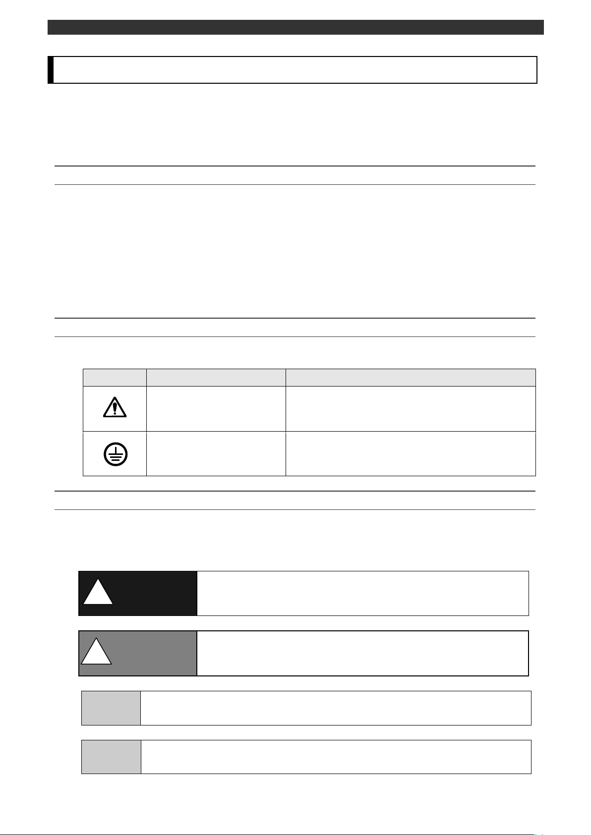
Alert symbol mark
Indicates the location which should refer to the
manual in order to prevent an electric shock and
injury.
Protective conductor
terminal
A terminal is provided for connection to the
protective conductor of the power supply facility for
the prevention of an electric shock.
Warning
The nonobservance of information under this symbol may result in
hazardous, critical or serious injury to the user.
Caution
The nonobservance of information under this symbol may result in a
hazardous situation or a light injury to the user or in physical
damage to the property.
Remarks
This symbol shows a caution when the instrument dose not function as specified
or when such a possibility exists.
Reference
This reference servers as a supplement for handling and operation, and it may be
convenient for the user.
!
!
1 For safe use
This section “For safe use” has been compiled to promote the correct use of the instrument in order to
prevent human injury or damage to property before they occur. If this instrument is used other than
description of this document, protection provided by the instrument may be vitiated. Please read the
following information carefully and be sure to observe the warnings and cautions in it.
1-1 Preconditions for use
This instrument is a component type general product to be mounted on an indoor instrumentation
panel. Do not use this instrument in different situations (except for portable type).
Before using this instrument, ensure the system safety by taking appropriate measures such as
fail-safe designing and periodic maintenance for the equipment to which this instrument is
installed. Connection, adjustment or operation of this instrument should be performed by a
professional engineer with knowledge of instrumentation.
Also, a person who handles this instrument should read this instruction manual to fully
understand the cautions and basic operations.
1-2 Labels on this instrument
The following labels are used for safe use.
1-3 Symbols in this manual
The cautions to be observed for preventing the damage of this instrument and unexpected
accidents are sorted by the following symbols according to their importance degrees for enabling
operators to use this instrument safely.
-5-
Page 8
INST.No.INE-882A KR2S/KR3S【Wiring/Installation】Instruction Manual
Warning
This paragraph covers important warning for safety to be observed
before reading the instructions. Fully understand the following
warning before reading this manual. These warnings are important
for preventing the damage to human bodies as well as accidents.
!
To the protective
conductor of power
supply facility
Switch
Overcurrent
protective device
(250V 3A)
L N
Power supply
Power terminal /
Protective
Conductor terminal
Power terminal/
Protective conductor
terminal
100-240V AC
50/60Hz 35VA MAX
100-240V AC
50/60Hz 60VA MAX
<KR2S>
<KR3S>
Power supply label
Power supply label
Switch and overcurrent protective device
This recorder is not provided with a
replaceable overcurrent protective device.
Prepare a switch and an overcurrent
protective device for the power supply
(circuit breakers, circuit protectors or the
like) within 3m of this recorder in a location
where the operator can access easily Use a
switch and an overcurrent protective device
conforming to IEC947-1 and IEC947-3.
Be sure to ground this instrument
Before turning the power on, connect the protective conductor terminal of this recorder to the
protective conductor of the power supply facility. In order to prevent an accident by electric shock, do
not disconnect this connection during operations.
Before turning on the power supply
In order to ensure safety, before turning on the external power switch, make sure that the power
voltage is within the range indicated on the power supply label.
Don't repair or modify this instrument
Make sure that any persons other than service engineers approved by CHINO CORPORATION do
not repair or modify this instrument by replacing parts. Otherwise it may be damaged or will not
function normally or an accident such as electric shock and burn may occur by putting your hand and
a tool in the internal unit. For ordinary operation, it is not necessary to pull out the internal unit.
Use this recorder following this instruction manual
Use this recorder correctly and safely by following this instruction manual. CHINO CORPORATION
will not be responsible for any injury, damage, lost profit or any other claim, which may result from
its wrong use.
-6-
Page 9

INST.No.INE-882A KR2S/KR3S【Wiring/Installation】Instruction Manual
Remarks
■
Fuse in the power supply
The following fuse is mounted in the power supply unit of this recorder for safety use.
However, this fuse is not replaceable
<KR2S>Maker: Nippon Seisen Co., Ltd Model: SLT 250V 2.5A
<KR3S>Maker: Littelfuse, Inc Model: 215 250V T3.5AH
Installing the safety device
Regarding the use of devices that anticipates a big loss due to failure of this instrument, always
install a safety device for preventing these losses and implement fail safe design in the final
instrumentation. Do not use this instrument in important in facilities related to, human life, atomic
energy, aviation and space.
Turn off the power supply if an abnormal symptom occurs
Turn off the power supply immediately and contact your local CHINO’s sales agent if any abnormal
odor, noise or any smoke occurs, or if this recorder becomes high temperature that is too hot to be
touched.
-7-
Page 10
INST.No.INE-882A KR2S/KR3S【Wiring/Installation】Instruction Manual
Model (Check with model code.)
Serial No.
KR2S**-***-***
K***********
MADE IN JAPAN
2 Before use
Check the following items before using the recorder. If something is wrong, contact your local CHINO's
sales agent.
2-1 Exterior check
Check that the instrument is not broken on the outer side.
2-2 Model check
The model number and serial number of this recorder can be confirmed by the label on the upper side
of the case.
Check the model of your instrument from the model code before use.
Model code
KR2S□P‐□□□
Measurement point/ Measuring period
6: 6 points/1 sec.
2: 12 points/1 sec.
Communication interface (Option)
N: None
E: Ethernet
R: Low/high order communications (RS-485)
G: Ethernet + low/high order communications (RS-485)
Alarm output, Contact input (Option)
0: None
2: Mechanical relay output (4 points ‘c’ contact)
7: No-voltage contact input (4 points)
8: Mechanical relay output (2 points ‘c’ contact) + No-voltage
contact input (2 points)
Installation type
A: Panel mounting type
T: Portable type (Grip and rubber feet attached)
*If the recording cycle is set less than 0.5 seconds (0.1 to 0.5 seconds), input channel point becomes 4
points automatically.
-8-
Page 11
INST.No.INE-882A KR2S/KR3S【Wiring/Installation】Instruction Manual
Model (Check with model code.)
Serial No.
KR3S**-***-***
K***********
MADE IN JAPAN
<KR3S>
KR3S□□‐□□□‐□□□
Measurement point/ Measuring period
2: 12 points/1 sec.
4: 24 points/1 sec.
6: 36 points/1 sec.
8: 48 points/1 sec.
Communication interface (Option)
N: None
E: Ethernet
R: Low/high order communications (RS-485)
G: Ethernet + low/high order communications (RS-485)
Alarm output, Contact input (Option)
0: None
2: Mechanical relay output (4 points ‘c’ contact)
7: No-voltage contact input (4 points)
8: Mechanical relay output (2 points ‘c’ contact) + No-voltage
contact input (2 points)
Installation type
A: Panel mounting type
Others (Option)
NNN: None
-9-
Page 12

INST.No.INE-882A KR2S/KR3S【Wiring/Installation】Instruction Manual
Parts name
Quantity
Remarks
Instruction
manual
1
INE-861□(General) CD-ROM
INE-863□(Communication interface)
(1 copy)
INE-862□(Wiring/Installation) A4 Booklet
1
RZMC-01-□(CF card)
Mounting
bracket
2
For panel mounting
Terminal screw
5
M3.5 for measuring input terminals (Spares for missing)
CF card
1
RZ-CMC256(256MB)
③Terminal screws
④CF card
②Mounting bracket
①Instruction manual
2-3 Checking attachments
Package contains the following attachments. Please confirm.
<KR2S>
-10-
Page 13

INST.No.INE-882A KR2S/KR3S【Wiring/Installation】Instruction Manual
Parts name
Quantity
Remarks
Instruction
manual
1
INE-881□(General) CD-ROM
INE-883□(Communication interface)
(1 copy)
INE-882□(Wiring/Installation) A4 Booklet
1
RZMC-01-□(CF card)
Mounting
bracket
2
For panel mounting
Wrench
1
Terminal screw
5
M3.5 for measuring input terminals (Spares for missing)
CF card
1
RZ-CMC256(256MB)
④Terminal screws
⑤CF card
②Mounting bracket
③Wrench
①Instruction manual
<KR3S>
-11-
Page 14

INST.No.INE-882A KR2S/KR3S【Wiring/Installation】Instruction Manual
Caution
Make sure to read and understand this instruction manual to
prevent any accident.
●Over voltage category ...... II (EN standard)
●Pollution degree ............... 2 (EN standard)
●Altitude.............................. 2000m or less
●Place of use ....................... Indoor
!
3 Installation
3-1 Mounting location
In order to avoid unfavorable effects on the measurement accuracy and recording operation, install
this recorder at the following locations.
1. Industrial environment
Select a place away from a source generating an electric field and/or a magnetic field and where
mechanical vibrations/shock is not existed.
2. Ambient temperature/humidity
Keep away from direct sunlight and do not close an area around this recorder to avoid
temperature increase.
●Place with stable ambient temperature of around 23°C and humidity 50%RH
●Place not exposed to hot blast (50°C or more) for avoiding deformation of the front panel
●Place where there are no wind and no heat source near terminals for avoiding measurement
errors.
3. Atmosphere
●Avoid a place where flammable gases and explosive gases exist.
●Avoid a place with dust, smoke, vapors, oil, chemical, corrosive gas, saline, iron, conducting
substance(carbon and iron), etc.
4. Mounting angle
●Lateral tilting ················0°
●Longitudinal tilting ········Forward tilting: 0°, Backward tilting: 0-20°
Mounting angle other than the above angles will have unfavorable effects on recording operation.
-12-
Page 15

INST.No.INE-882A KR2S/KR3S【Wiring/Installation】Instruction Manual
3-2 External dimensions
The following figure shows the dimensions of this recorder with its mounting brackets.
<KR2S>
Unit : mm
<KR3S>
Unit : mm
-13-
Page 16

INST.No.INE-882A KR2S/KR3S【Wiring/Installation】Instruction Manual
Caution
Mount on the panel and use
This instrument has been designed to be mounted on an indoor
instrumentation panel.
Use a panel made of a steel plate of 2mm to 6mm in thickness or a
panel equivalent in strength. Please consider the instrument's
dimensions and its weight when you select the panel thickness
along with the panel structure.
When you attach this instrument to a panel, be careful of the
injury by fall.
!
パネルカット
パネルカット
360
360
281
+1
0
281
+1
0
●Minimum interval for installation of multiple instruments
(Unit: mm)
(Unit: mm)
パネルカット
パネルカット
200
200
138
+1
0
138
+1
0
●Minimum interval for installation of multiple instruments
(Unit: mm)
(Unit: mm)
3-3 Method of mounting the panel
1. Panel cutout size
<KR2S>
<KR3S>
-14-
Page 17

INST.No.INE-882A KR2S/KR3S【Wiring/Installation】Instruction Manual
Mounting bracket
Mounting bracket
Panel thickness (2 to 6 mm)
Mounting bracket
Mounting bracket
Panel thickness (2 to 6 mm)
2. Mounting method
<KR2S>
(1) Insert this recorder into the panel cutout from the front of the panel.
(2) Insert the mounting brackets into the holes of the top and bottom sides, and fix them with
screws using a Phillips screwdriver. Set the tightening torque on screws to 1.0 N•m (when
using Phillips-head screwdriver).
<KR3S>
(1) Insert this recorder into the panel cutout part of an instrument panel.
(2)Since there is a screw hole each (a total of two holes) in the right and left sides of this recorder,
screw 2 fixing screws attached in two holes lightly.
(3)Next, put the hexagon head of this screw to the circular hole of the mounting bracket and
push the recorder to the instrument panel firmly (from front) while making the mounting
bracket slide as shown in the figure. On this condition, tighten the fixing screw with the
attached wrench or a Phillips screwdriver.
Set the tightening torque on screws to 2.0 N•m (when using Phillips-head screwdriver).
*Note that the mounting brackets used at the right and left sides are different (mounting work
should be performed by two persons).
-15-
Page 18

INST.No.INE-882A KR2S/KR3S【Wiring/Installation】Instruction Manual
RS-485
Ethernet Connector
Measurement input terminal
TC / mV(+) / RTD(A)
TC / mV(-) / RTD(B)
RTD(B)
Alarm output(option)
‘c’ contact output:
4points/terminal block
Communications terminals(option)
[CH1~12]
[CH13~24]
[CH25~36]
[CH37~48]
Power terminal
Protective conductor terminal
Alarm output(option)
‘c’ contact output:
4points/terminal block
Power terminal
Protective conductor terminal
RS-485
Ethernet Connector
Communications terminals(option)
Measurement input terminal
TC / mV(+) / RTD(A)
TC / mV(-) / RTD(B)
RTD(B)
4 Connections
4-1 Terminal board arrangement
The following diagram shows the terminal board arrangements in which option (Mechanical relay
output [4 points ‘c’ contact], communication interface) are mounted.
<KR2S>
<KR3S>
-16-
Page 19

INST.No.INE-882A KR2S/KR3S【Wiring/Installation】Instruction Manual
SA SB SG
Ethernet connector
[Option terminal block]
Alarm relay output (4 points ‘c’ contact)
No-voltage contact input(4 points)
Alarm relay output (2 points ‘c’ contact) + No-voltage contact input(2 points)
Communication terminals
-17-
Page 20

INST.No.INE-882A KR2S/KR3S【Wiring/Installation】Instruction Manual
Warning
Alert symbol marks
( )
and places
The alert mark is pasted at danger places where may causes
electric shock. (See the following table).
Name of terminals
Places marked with the symbol
Power terminals
Lower left of power terminals
Measurement input terminals
Upper left of terminal cover
Mechanical relay ‘c’ contact
alarm terminals
Lower left of terminal cover
Reference
Input terminal block is removable
The input terminal block is removable for easy connections.
(1) Each terminal block can be removed by removing mounting screws.
(2) Each terminal block is connected to the recorder by a connector.
Input 12 points
Input 6 points
Caution
Turn off the power supply in advance
For mounting or dismounting the terminal block,
turn off the external power switch to prevent the
electric circuits from being damaged.
Remarks
■
Replacement of input terminal block
Input terminal block cannot be replaced by other terminal block.
If replaced measurement error occurs.
!
!
Mounting screws
Terminal block
Mounting screws
Terminal block
-18-
Page 21

INST.No.INE-882A KR2S/KR3S【Wiring/Installation】Instruction Manual
Warning
A switch and an overcurrent protective device
Prepare a switch and an overcurrent protective device (3A) to
the power supply for preventing an electric shock accident
during connection work. This recorder is not provided with any
replaceable fuse.
Turn off the power supply before connections
Be sure to turn OFF the power supply before connecting cables
to the power and the input/output terminals to prevent an
electric shock.
Major noise sources
Counter measures
●Electromagnetic switch, etc.
●Power line having waveform distortion
●Inverter
●Thyristor regulator
Insert noise filters between power terminals
and input/output terminals. A CR filter is often
used.
!
4-2 Precautions while connections
Observe the following cautions during connections for securing safety and reliability.
4-2-1
Power supply
Use a single-phase power supply having a stable voltage without any waveform distortion for the
purpose of preventing wrong operations.
4-2-2
Keep the input/output connections away from a high voltage power circuit
Don’t place the input/output cables close or in parallel with any strong power circuits including
power line. Place the cables 50 cm or more away from high voltage power circuits when they are
placed close or in parallel to other circuits.
4-2-3
Keep the thermocouple input away from a heat source
For thermocouple inputs, keep the input terminals away from a heat source (a heating body) to
reduce a reference junction compensation error.
Don’t expose the input terminals to direct sunlight, etc.
4-2-4
Keep all connection cables away from noises
Keep all connection cables away from noise source as far as possible, otherwise unexpected
malfunction may occur. Provide a solution if the cables cannot be separated from a noise source
due to unavoidable circumstances.
4-2-5
Use crimp style terminals
Fix crimp style terminals to termination of connection cables for preventing the looseness or
disconnection of terminals and a short-circuit failure between terminals.
Use the crimp style terminals with insulation sleeve for preventing an electric shock.
-19-
Page 22

INST.No.INE-882A KR2S/KR3S【Wiring/Installation】Instruction Manual
Warning
■Secure the connected cables properly.
Secure the connected cables so as not to allow them to be hooked by
a person or a substance, otherwise the connections may be cut and
disrupted that may cause an electric shock or other accidents.
Terminal name
Screw
diameter
Tightening
torque
Termination (Unit: mm)
Power and
protective
conductor and
communication
terminal
M4
1.2N・m
Type O
Input terminal
M3.5
0.8N・m
Type O
Type Y
*Use Type O whenever possible.
Alarm relay
output,
non-voltage
contact input
terminal
M3.5
0.8N・m
Type O
Type Y
*Use Type O whenever possible.
Communication
terminal
M3
0.5N・m
Type O
Type Y
*Use Type O whenever possible.
!
More than 3.7
Less than 7.0
Less than 7.0
t:0.8
t:0.8
With an insulation sleeve
With an insulation sleeve
More than 3.7
More than 3.2
Less than 6.2
Less than 6.2
t:0.8
t:0.8
With an insulation sleeve
With an insulation sleeve
More than 3.2
More than 4.3
Less than 8.0
With an insulation sleeve
t:0.8
More than 3.7
Less than 8.0
Less than 8.0
t:0.8
t:0.8
With an insulation sleeve
With an insulation sleeve
More than 3.7
4-2-6
Unused terminals
Don’t use any unused terminals for relaying; otherwise the electric circuits may be damaged.
Kinds of terminals and termination
-20-
Page 23

INST.No.INE-882A KR2S/KR3S【Wiring/Installation】Instruction Manual
Warning
Turn off the power supply
Be sure to turn off the power supply before connecting the cable to
the power supply and protective conductor terminals to prevent an
electric shock.
!
Protective conductor terminal
Power terminals
L N
Power supply (voltage, frequency, power consumption)
100-240V AC
50/60Hz 35VA MAX
Protective conductor terminal
Power terminals
L N
Power supply (voltage, frequency, power consumption)
100-240V AC
50/60Hz 60VA MAX
4-3 Connection of power and protective conductor terminals
4-3-1
Power and protective conductor terminals
<KR2S>
l
<KR3S>
-21-
Page 24

INST.No.INE-882A KR2S/KR3S【Wiring/Installation】Instruction Manual
Warning
mark at power terminals
A voltage of 100 to 240 V AC is applied to the power terminals after
connection. Be sure to mount the power terminal cover to prevent an
electric shock.
Caution
Be careful with the power voltage and noise
The power voltage of this instrument is indicated beside the power
terminals.
Don’t apply any voltage other than indicated; otherwise a
malfunction may result.
If noise is generated at the power supply, provide a noise reduction
transformer, etc.
Remarks
L/N indication of power terminals
This indication conforms to the CSA standard, Canada. The live side of the
single-phase AC power supply is indicated as L, and the neutral side is indicated as
N. Observe the L and N connections for obtaining satisfactory performance.
!
!
4-3-2
Connection of power terminals
For connection to the power terminals, use a 600 V PVC insulated cable terminated by the crimp
style terminals with insulation sleeve.Note) Use the cords approved by the following standards.
(1) IEC 227-3
(2) ANSI/UL817
(3) CSA C22.2 No.21/49
4-3-3
Connection of protective conductor terminal
Be sure to connect this terminal to the protective conductor of the power supply facility. For this
connection, use a cable terminated by the crimp style terminals with insulation sleeve.
・Grounding wire: Copper wire 2 mm2 or more (green/yellow)
L N Mount the terminal cover after connections.
A copper wire with 2 mm2 or more (green/yellow)
Be sure to connect to the protective
conductor of the power supply facility.
600 V vinyl insulated cable
Power supply
-22-
Page 25

INST.No.INE-882A KR2S/KR3S【Wiring/Installation】Instruction Manual
Caution
Allowable input voltage
Input type
Allowable input voltage
Voltage, thermocouple input
±
10VDC*
Resistance thermometer input
±
6VDC
*
±
60 VDC with channel settings to the
±
5 V or higher range.
Remarks
Isolation of measured input terminal
TC, mV(+), RTD(A) terminal and TC, mV(-), RTD(B) terminal are insulated each
channels but RTD(B) terminal is short-circuited between channels.
!
(+)
(-)
DC voltage input
Twisted cable for instrumentation
4-4 Connection of measuring input terminals
4-4-1
Measuring input terminals
Be sure to turn off the power supply to prevent an electric shock.
For the connections to the input terminals, use cables terminated by the crimp style terminals
with insulation sleeve.
4-4-2
Connections of DC voltage (current) input
Use twisted cables for instrumentation as the input cables for the purpose of suppressing noises.
For current inputs, mount shunt resistors to the channels to be measured before connections.
●DC voltage (Current) input
1 2 3 4 5 6
4-4-3
Connection of thermocouple (TC) inputs
Be sure to use thermocouple wires (or extension wires) to the input terminals of this recorder. If a
copper wire is used halfway, a noticeable measuring error occurs. If using a pair of thermocouple
wire in parallel, it may have an influence on the measurement.
When it is necessary to operate the instrument in this situation, check for no influence while
operating the instrument before using.
●Thermocouple (TC) input
1 2 3 4 5 6
(+)
(-)
Extension wire
Thermocouple
-23-
Page 26

INST.No.INE-882A KR2S/KR3S【Wiring/Installation】Instruction Manual
Warning
mark of measuring input terminals
A high voltage may be applied to the measuring input terminals due
to common mode noises. The allowable noise value is lower than 30
VAC or lower than 60 VDC. Make sure that the noises are lower
than the allowable values. Mount the terminal cover after
connections for the purpose of preventing an electric shock and to
protect the input wires. In the case of thermocouple input, the
mounting of the terminal cover can reduce the reference junction
compensation error.
!
4-4-4
Connection of resistance thermometer (RTD) input
Use a 3-core cable where each lead wire has an equal resistance value. Don’t use one resistance
thermometer in parallel with other instruments (controller, etc.).
●Resistance thermometer (RTD) input
1 2 3 4 5 6
A
B
B
3 core cable (Same diameter, same length)
Resistance thermometer
*The resistance of each cable is less than 10 Ω. All the
3 wires should be of the same resistance value.
-24-
Page 27

INST.No.INE-882A KR2S/KR3S【Wiring/Installation】Instruction Manual
Alarm relay output 4 points (‘c’ contact)
Alarm relay output 2 points (‘c’ contact)
DO1 DO2 DO3 DO4
DO1 DO2
4-5 Connection of alarm output terminals (Option)
This is for the recorder with alarm output terminals (Option).
4-5-1
Alarm output terminal
The terminal arrangement depends upon the type of alarm output.
-25-
Page 28

INST.No.INE-882A KR2S/KR3S【Wiring/Installation】Instruction Manual
*N.C terminal - Open relay contact at alarm activation that
is the reverse action to N.O terminal.
N. O
COM
N. C
*
Load
This recorder
: Contact protective element (It is recommended to
mount this element on the a side)
b
Buffer relay
Power Supply
a
Warning
mark of alarm output terminals
Connect a load not exceeding the specified contact capacity to the
alarm output terminals. If the voltage more than 30VAC/60VDC is
to be applied to the alarm output terminal, use type O crimp style
terminal with an insulation sleeve to connect double-insulated
wires (dielectric strength of 2300 VAC or more) for the signal wires
and for the other signal wire use basic insulated wires (dielectric
strength of 1390 VAC), If the voltage more than 30VAC/60VDC is
to be applied to either alarm output terminal of channel, use
double-insulated wires or reinforced insulation for external circuit
of all the channels. A buffer relay power supply is applied to the
alarm output terminals after connections. Do not touch these
terminals since an electric shock will occur. Be sure to mount the
terminal cover after connections.
Caution
Take a safety measure.
An alarm output of this recorder may become defective caused by
wrong operation, failures, and other abnormal inputs.
Take a safety measure against an output failure before use as
occasion calls.
Example of mechanical relay ‘c’ contact outputs
!
!
4-5-2
Connections
Turn off the power supply and buffer relay power supply before connections to prevent an electric
shock.
(1) Connect cables to the load via a buffer relay.
(2) Use cables with the crimp style terminals with insulation sleeves for the alarm output
terminals. Only one crimp style terminal is allowed to connect to the terminal.
-26-
Page 29

INST.No.INE-882A KR2S/KR3S【Wiring/Installation】Instruction Manual
Item
Contents
Contact rating of
Mechanical relay outputs
(‘c’ contact)
Power
supply
Resistive
load
Inductive
load
100V AC
3A
1.5A
240V AC
3A
1.5A
30V DC
3A
1.5A
Mounting of contact
protective element Z
●Mount a contact protective element conforming to the buffer
relay. The relay is broken, if a signal exceeding the contact rating
is applied even if momentarily.
●To prevent a malfunction being caused by a light load, the most
effective mounting position for the element is on the coil side of
the buffer relay (refer to “4-5-2 Connection” example of
mechanical relay ‘c’ contact outputs diagrams)
Selection of buffer relay
(1) Coil rating .......... Less than the contact rating of output
terminals
(2) Contact rating ... More than twice the load current
A coil surge absorption element built-in type relay is
recommendable. Mount an additional buffer relay if a buffer
relay satisfying the load rating is not available.
Selection of contact
protective element
Mount a contact protective element if a surge absorption element
built-in buffer relay is not available. This element is generally
composed of C (capacitor) and R (resistor).
<Reference values of C•R> C: 0.01 µF(Rating about 1 kV)
R:100 to 150 Ω(Rating about 1 W)
(Minimum load)
100mA 5VDC
4-5-3
Precautions for connection
Be careful with the following cautions for connections.
-27-
Page 30

INST.No.INE-882A KR2S/KR3S【Wiring/Installation】Instruction Manual
No-voltage contact input(4 points)
No-voltage contact input(2 points)
Remarks
Features of digital input terminal
Voltage when the contact is open. : Approx. 5 V
Current when the contact is short. : Approx. 2 mA
DI1 DI2
DI1 DI2 DI3 DI4
4-6 Connection of digital input terminals and function
selection (Option)
This is for the recorder with digital input terminals (Option)
4-6-1
No-voltage contact input terminal
-28-
Page 31

INST.No.INE-882A KR2S/KR3S【Wiring/Installation】Instruction Manual
Caution
No-voltage contacts
For the contacts to be connected to the Digital input terminals, use a
switch or relay driven at lower than 30 V AC or lower than 60 V DC,
or manual contacts for very light loads.
Example of connections(No-voltage contact input(4 points))
!
COM
DI1 DI2 DI3 DI4
4-6-2
Connections
Turn off the power supply before connections to prevent an electric shock.
Apply a no-voltage contact signal to digital input terminals.
Use cables terminated by crimp style terminals with insulation sleeves for the digital input
terminals.
4-6-3
Functions of terminals
Digital input ······ ON/OFF (short/open) state can be measured. Select the range type as DI.
(Refer to ‘9-1 input operation settings’.)
Pulse input ········ Used as the pulse input. Select the range type as Pulse (+) and Pulse (-).
(Refer to ‘9-1 input operation settings’.)
Totalizer reset ···· he reset of totalizer is executed. When the digital input terminal specified
becomes ON, the totalizer reset is executed.
(Refer to ‘9-6 Totalizer reset settings’.)
Marker ·············· The writing of marker. The marker can be written on the trends when the
digital input terminals become ON.
(Refer to ‘9-8 Marker text settings’.)
File drive ··········· The recording start/stop of data file in the internal memory is executed.
The recording starts or stops when the digital input terminals become ON or
OFF.
(Refer to ‘9-5 File settings’.)
●Each function requires a short circuit of 0.1 second or more between the COM terminal and
each terminal.
-29-
Page 32

INST.No.INE-882A KR2S/KR3S【Wiring/Installation】Instruction Manual
Turn the switch of RS-422A/RS-485
to RS-485.
Avoid connecting SG line to FG terminal or ground terminal of the
device.
Termination
resistor
100Ω
Device side
Protocol converter
SC8-10
1
2
3
4
5
6
7
8
Cable for RS-232C(Max. 15m)
RZ-CRS6□□
Communication port
PC side
RD
SD
SG
RD
SD
SG
RDA
RDB
SA
SB
SG
SA
SB
SG
SA
SB
SG
4-7 Connection of communication I/F terminal (Option)
The KR can be communicated with a master unit (high order instrument) via Ethernet and RS-485,
and with a slave unit (low order instrument) via RS-485.
*Ethernet and RS-485 communication function are optional.
RS-485 terminal Ethernet connector
SA SB SG LAN Active LED(Green) LINK LED(Orange)
4-7-1
Connections of High order communication RS-485
The RS-485 communications interface is connected to a personal computer via a protocol converter.
Three signals of SA, SB and SG are used between the protocol converter and a personal computer
and a control signal is not used. Wiring process of connector differs from how the personal computer
uses the control signal hence please understand your personal computer.
-30-
Page 33

INST.No.INE-882A KR2S/KR3S【Wiring/Installation】Instruction Manual
SA
SB
SG
Avoid connecting SG line to FG terminal or ground terminal of the device.
Termination
resistor
100Ω
This recoder
Termination
resistor
100Ω
SE3000, MELSEC, etc
AL3000, etc.
SA
SB
SG
RDA
RDB
SDA
SDB
SG
Turn the switch of RS-422A/RS-485
to RS-485.
Avoid connecting SG line to FG terminal or ground terminal of the device.
Termination resistor
100Ω
This recorder
Line converter
SC8-10
Cable for RS-232C(Max.15m)
RZ-CRS6□□
Communications port
SYSMAC CPU unit
Internal RS-232C port
(D-SUB 9-pin receptacle)
RD
SD
SG
RDA
RDB
SA
SB
SG
RD
SD
SG
1
2
3
4
5
6
7
8
4-7-2
Connections of low order communication RS-485
Connect SA1, SB1 of KR3S and SA, SB of low order connected instrument like the following figure.
Refer to instruction manual of each instrument for detail method of low order instrument connection.
Example of terminal connection 1
Example of terminal connection 2(SYSMAC)
-31-
Page 34

INST.No.INE-882A KR2S/KR3S【Wiring/Installation】Instruction Manual
Device side
HUB
Straight twist-pair cable
with shield(Max.100m)
PC side
HUB
Straight twist-pair cable
with shield(Max.100m)
Straight twist-pair cable
with shield(Max.100m)
Crossover twist-pair cable
with shield(Max.100m)
Device side
PC side
4-7-3
Ethernet wiring
① Example of connection between PC and Ethernet devices(one-to-one connection)
② Example of connection between PC and HUB/Ethernet devices(one-to-N connection)
-32-
Page 35

INST.No.INE-882A KR2S/KR3S【Wiring/Installation】Instruction Manual
Page 36

32-8,KUMANO-CHO,ITABASHI-KU,TOKYO 173-8632
Telephone :81-3-3956-2171
Facsimile :81-3-3956-0915
E-mail: inter@chino.co.jp
Printed in Japan
 Loading...