

Page 1

INST.No.INE-508-P0
IR-E Series
Scanning Radiation Thermometer
Store this manual in a readily acc essib le
location for future reference.
This manual should be provided to the person who
actually uses this product.
(Detector Unit, Accessories)
Instruction Manual
Page 2

INST.No.INE-508-P0
Preface
Thank you for purchasing the IR-E series scanning radiation thermometer.
Read this manual carefully to ensure that you use this product correctly and safely.
Request to
Request to
Installation contractor/distributors
Provide this manual to the person who actually uses this product.
Person who uses this product
Correctly use this thermometer according to this manual.
This manual is required for maintenance of this product, too. Store it until this unit
is disposed.
Should any unclear points arisen or any technical assistance be required, contact
your sales agent of CHINO Corporation.
Notices
1. The contents of this manual are subject to change without notice.
2. Should any defects in bookbinding such as paging disorder, pages missing, etc., or any suspicious
points, errors or omissions in the contents be found, contact your nearest agent of CHINO
Corporation.
3. The intellectual property rights of this manual belong to us.
Do not disclose the contents of this manual, in part or in whole, to a third person without our
permission.
- Front 1-
Page 3
INST.No.INE-508-P0
Important Operational Instructions
!
For using this thermometer correctly and safely, make sure to observe the following safety
instructions before attempting to operate or store it.
1. Working conditions and environment
∙ The working temperature range of this thermometer is 0 to 50°C. (No dew condensation)
∙ Avoid using this thermometer in environments where dusts, fine particles, corrosive gas exist.
∙ This thermometer is a precision instrument. Avoid using in places with widely varied ambient
temperature, high humidity, places close to strong electricity circuits, and places with
mechanical vibration and shock.
2. Storage
∙ For storing this thermometer, avoid places with high temperature and humidity.
∙ When this thermometer has any trouble, do not disassemble it by yourself but contact your
nearest sales agent/distributor of CHINO Corporation.
3. Symbols used in this manual
The following symbols are used depending on important degrees of warnings/cautions to operate this
thermometer safely and to avoid malfunctions or unexpected situation.
Important
degree
1
2
3
4
5
Symbols Contents
!
Warning
This symbol is indicated with a title for an explanation
with . .
Warning
Indicates important information that must be observed to avoid the
risk of fire or electric shock or other dangers that may result in serious
personal injury or death, or damage to this product.
Caution
Remarks
Reference
Indicates important information that must be observed to avoid the
risk of personal injury or malfunctions of this product.
Indicates supplementary information that the operator is recommended
to understand.
Indicates supplementary information or a reference to an operation.
- Front 2-
Page 4
INST.No.INE-508-P0
!
!
Warnings and Cautions
¡ Please observe the following safety precautions fully to use this product correctly.
In addition, please read this manual carefully and store it in a readily accessible location for future
reference.
The mark indicates actions that are prohibited during operation.
Warning (May cause death or serious personal injury)
!
Do not operate this thermometer in places where flammable or volatile gas exists. It is
very dangerous to use this thermometer under such environment.
To prevent electrical shock, make sure to turn off the power source before the power
!
connection work.
Should this thermometer be damaged, or any smoke or unusual odor be emitted, do
not use it. It may result in the risk of fire.
!
Turn off power immediately and contact your nearest sales agent of CHINO
Corporation.
Repairing or modification of this thermometer may result in failure and also be
!
danger. Never attempt to repair or modify this thermometer.
!
Caution (May cause personal injury or property damage)
Avoid using in places with widely varied ambient temperature, high humidity, places close
!
to strong electricity circuits, and places with mechanical vibration and shock.
For using this thermometer safely, comply with the descriptions and handling instructions in
this manual. Failure to comply with the descriptions and instructions may result in damage to
or functional decline of this thermometer or damage to the equipment.
- Front 3-
Page 5

INST.No.INE-508-P0
CONTENTS
1. Introduction ················································································· 1
1.1 General·································································································· 1
1.2 Model code ····························································································1
1.3 Measurement ranges ··············································································1
2. Configuration···························································································2
3. Detector unit················································································ 3
3.1 Names and functions of parts ·································································3
3.2 Installation ····························································································4
3.3 Precautions for installation····································································· 5
3.4 Layout of connecting cables ···································································6
3.5 Connections ···························································································6
3.6 Operation ······························································································6
4. Accessories·················································································· 7
4.1 Protective case Model: IR-ZEPW ···························································7
4.1.1 Installation··························································································8
4.1.2 Housing the detector unit ····································································8
4.2 Air-purge hood Model: IR-ZEAH···························································9
5. Maintenance ················································································ 10
5.1 Periodical maintenance··········································································10
5.2 Trouble shooting····················································································10
6. Specifications ·············································································· 12
-Contents-
Page 6
INST.No.INE-508-P0
1. Introduction
1.1 General
The IR-E series scanning radiation thermometer, having a rotary mirror built in the detector
unit, is designed to measure unidirectional temperature patterns of an object without contact
and performs the temperature measurement of 50°C to 1200°C.
The IR-E series consists of the detector unit (Model IR-E) and the high-speed
display/processing unit (Model IR-EPG), and exclusive accessories of the protective case and
the air-purge hood for the detector unit are added as needed.
The detector unit measures the thermal radiation energy from a measuring area by scanning
measuring positions optically by the rotary mirror, and converts the measured temperature into
an electric signal that is transmitted to the high-speed display/processing unit with an
exclusive connecting cable.
The connecting cable is shipped with the length specified, but the cable length can be changed
within 200m without any effect to functions.
The high-speed display/processing unit performs indication/recording and analog output of the
measured temperature after arithmetic processing such as emissivity compensation,
linearization, signal modulation, etc. on the temperature pattern signal transmitted from the
detector unit.
2 kinds of connection types of a connector connection and a terminal connection are available
on the detector unit. The connection type of your detector unit has been selected by your
ordering specification.
This manual describes operations and configurations of the detector unit, the protective case
(Model IR-ZEPW), and the air-purge hood (Model IR-ZEAH). Confirm the name and model of
the instrument you purchased and read corresponding paragraphs in this manual.
A separate manual is prepared for handling/operation of the high-speed display/processing unit,
read it along with this manual.
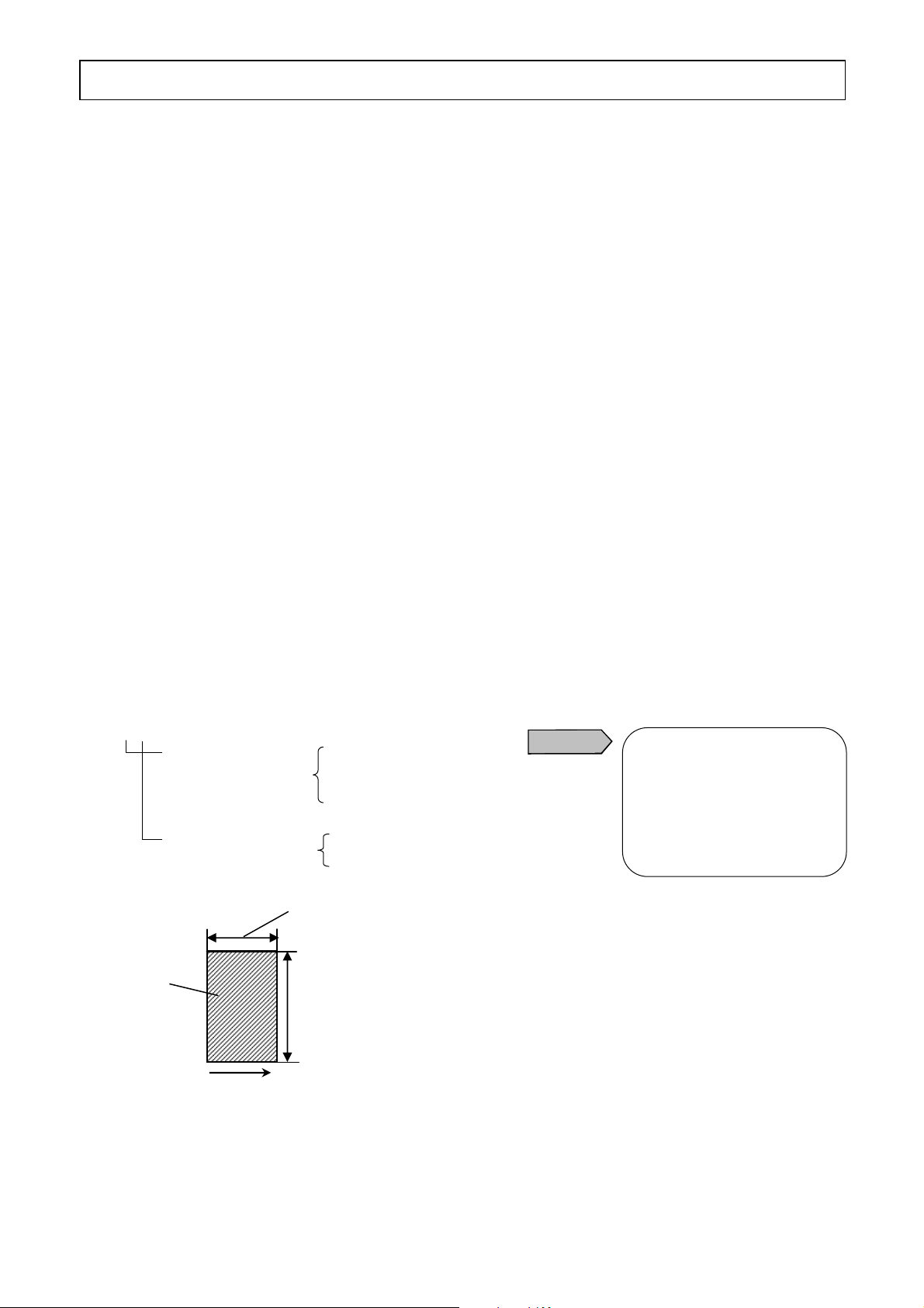
1.2 Model code
Detector unit
IR-E (a×b)
Distance factor 0 : 50 ( 50× 50)
1 : 100 (100×100)
2 : 200 (200×100)
Connection type T : Terminal connection
C : Connector connection
Instantaneous
view
Scanning direction
Distance factor a (200)
Distance factor b (100)
Ì The t erm of the distance factor is the
Caution
The term of the distance
factor indicates one side of
the scanning direction. For
the instantaneous view,
refer to the following
figure.
“distance factor a”.
The numbers shown in parentheses
are for the distance factor of 200.
1.3 Measurement ranges
50 ~ 300°C, 100 ~400°C, 200 ~ 600°C, 300 ~ 800°C, 400 ~ 1000°C, 500 ~ 1100°C,
600 ~ 1200°C
-1-
Page 7

INST.No.INE-508-P0
2. Configuration
The IR-E series scanning radiation thermometer consists basically of the detector unit, the
relay box and the high-speed display/processing unit. Unidirectional temperature patterns,
trend graphs and thermal images are displayed on the high-speed display/processing unit.
The scanning radiation thermometer detector unit (Model IR-E) and the relay box (Model
IR-ZEB) are connected with the exclusive connecting cable (Model IR-ZEST or IR-ZESC).
The connecting cable has been shipped with the length specified, but the cable length can be
changed within 200m without any effect to functions.
For the scanning radiation thermometer detector unit, in addition to the detector unit, the
protective case (Model IR-ZEPW) for housing the detector unit in the temperature
measurement at a site under such hostile environment as high temperature, high humidity,
smoke, dust, oily smoke, etc. and the air-purge hood (Model: IR-ZEAH) for clearing the
optical path are prepared as accessories.
Scanning radiation
thermometer
detector unit
IR-E
IRE
CHINO
Connecting
cable
IR-ZES
Relay box
IR-ZEB
Connecting
cable
100VAC
-
High-speed
display/processing unit
IR-EPG5F
Connecting cable
IR-ZERC
Temperature
output
0 to 5VDC
(Non-isolated)
100 to 240VAC
-2-
Page 8

INST.No.INE-508-P0
3. Detector unit
The detector unit is a single-color narrow-band radiation thermometer using the detecting element
of PbSe (4.0μm measuring wavelength). Its drive power is supplied from the relay box. By
scanning the measuring area optically by the hexahedron rotary mirror, it measures
unidirectional temperature patterns of an object and transmits the measured temperature as the
electric signal of 0 to 1mADC to the relay box.
In the relay box, the electric signal of 0 to 1mADC is converted to 0 to 5VDC that is transmitted
to the high-speed display/processing unit.
It measures temperature with the wide scanning angle of 50° and the high scanning speed is as
fast as 50 times/second.
2 kinds of connection types of the connector connection and the terminal connection are
available. The connection type of your detector unit has been selected by your ordering
specification.
3.1 Names and functions of parts
Names Functions
Detector unit
Measurement window
Distance setting axis
Setting distance display window
Connector
(For connector connection type)
Terminal board
(For terminal connection type)
Detector unit fixing hole
Setting distance
display window
Functions of an optical system, electric circuits, etc.
required for a detector unit are built-in.
This window is for taking the radiant energy from a
measuring area into the detector unit.
It is required to always keep it clean.
This axis is for bringing the detector unit into focus on
a measuring area.
While looking through a setting distance display
window, turn this axis with a flathead screwdriver to
adjust the measurement distance on a marker.
The measurement distance set by the distance setting
can be confirmed.
This connector is for the connecting cable between the
detector unit and the relay box.
This terminal board is for the connecting cable between
the detector unit and the relay box.
This hole is for fixing the detector unit in place.
With 2 pieces of M20 bolts, fix the unit to a mounting
angle, a mounting plate, etc.
When the protective case is used, fix the unit by
inserting 2 guide supports through the fixing holes.
Detector unit fixing hole
Measurement
window
Connector
Terminal board
Distance setting axis
-3-
Page 9

INST.No.INE-508-P0
(
)
3. Detector unit
3.2 Installation
The external and mounting dimensions are shown below. Fix the detector unit with 2 pieces of
M20 bolts to a fixing plate like a mounting angle, a mounting plate, etc. so that the
measurement window is parallel to a measuring area and is positioned with the center line of a
measuring area.
The measurement distance of the detector unit can be arbitrarily changed in 0.5 to 10m. When
the installation is completed, perform the distance setting by turning the distance setting axis.
When the protective case and the air-purge hood are used, refer to the paragraphs shown
below.
x Protective case x x x Refer to [4.1 Protective case Model: IR-ZEPW].
x Air-purge hood x x x Refer to [4.2 Air-purge hood Model: IR-ZEAH].
In case of connector connection
IRE
25
200
CHINO
20
370
50°
120
60
410
450
-4-
Unit: mm
Page 10

INST.No.INE-508-P0
3. Detector unit
3.3 Precautions for installation
(1) Vibration and impacts
The detector unit is designed to withstand the vibration of 29.4m/s2 (3G), but vibration or
impacts reduce the liability of the detector unit in the long term and cause an unstable
measurement by the position movement of a measuring area.
When vibration is intense especially, it is effective to insert cushion materials like a rubber
board between the detector unit and a fixing stand.
(2) Induction
The detector unit is designed for anti-induction but install it as far as possible from
induction heating equipment or power lines.
(3) Working temperature and humidity
The working temperature of the detector unit is 0 to 50°C. When the ambient temperature
is higher than 50°C or reflection from a measuring area or hot air is strong, use the
protective case for cooling the detector unit by water.
When the ambient temperature does not exceed but closely reaches to 50°C, it is recommended
to cool the detector unit by water for maintaining of its reliability.
In addition, control humidity in environment as low as possible. High humidity absorbs and
scatters thermal radiation in the optical path.
(4) Optical path
Select a place where water-drops, dust, smoke, steam, etc. do not enter between the detector
unit and a measuring area.
If such place cannot be selected and the affection by existence of such substances cannot be
ignored, purge such substance with air or other arrangements are necessary.
(5) Measurement distance
The measurement distance of the detector unit can be arbitrarily changed in 0.5 to 10m but,
since the scanning angle is constant, the scanning width of a measuring area becomes large
as the measurement distance becomes large.
Allow for a margin of the scanning width in consideration of fluctuation of a measuring
area, displacement of the optical path, etc.
Scanning width = 2 X (Measurement distance + 47) x tan25°
Scanning
angle
50°
Scanning width
Scanning center
47
Measurement
distance
-5-
Page 11

INST.No.INE-508-P0
3. Detector unit
3.4 Layout of connecting cables
For connecting the connecting cables, be careful of the following points.
Caution
3.5 Connections
(1) Connections of terminal connection type
By removing the terminal board cover on the
upper side of the detector unit, 5 pieces of
terminals are arranged as shown in the right
figure.
Connect wires of the connecting cable to each
terminal.
Since the wires of the connecting cable are
identified by colors, connect them as shown in
the right figure.
Caution
Remarks
(2) Connection of connector connection type
The connection is completed by coupling the connector of the connecting cable to the
connector on the upper side of the detector unit.
x For the coupling, position key slits of both connectors and push the cable connector,
and turn the detachable ring clockwise until it is locked.
x For decoupling, turn the detachable ring counterclockwise for unlocking and pull the
cable connector.
(1) Separate the cables from induction heating equipment and power lines.
(2) Keep the cables free of deposit of water, oil, etc.
(3) Don’t bend the cables extremely or apply any excessive force to them.
(4) Avoid laying the cables at a place in high temperature more than 70°C.
(5) For laying the cable permanently, protect them with conduits, etc.
The outside diameter of the connector attached to the cables is about
ø23mm.
Black White Red
Yellow
Shield
The terminal board is exclusively
used for connection with the
+ - AC100V
relay box. Do not connect a
power line, etc.
OUTPUT POWER EARTH
The power for the detector unit
is supplied from the relay box
through the connecting cable.
3.6 Operation
Since the drive power is supplied to the detector unit from the relay box, when the relay box is
turned on, the detector unit automatically becomes ready to measure.
However, when the protective case and/or the air-purge hood are used, confirm that cooling
water and/or purge air are supplied in advance.
By starting up the software of the high-speed display/processing unit and then clicking the
measurement start button, the detector unit is put into operation.
-6-
Page 12

INST.No.INE-508-P0
g
530
4. Accessories
4.1 Protective case Model: IR-ZEPW
When the detector unit is placed under such hostile environment as high temperature, high
humidity, smoke, dust, oily smoke, etc., this protective case is used for housing the detector
unit.
At the cooling-water inlet/outlet and the purge air inlet, R1/2 screws are used.
Names Functions
Remove this cover to take or wire to the detector unit.
Upper cover
Cable gland
Inner purge air inlet
Purge air inlet
Exchange window
Cooling water
inlet/outlet
Fixing hole
Cooling water outlet
226
Cooling
water
245 245
Exchange window
Pressure 0.3MPa max
Flow 1 ~ 5ℓ/min
Temperature Lower than 40°C at the outlet
Air Clean air
Purge air
Pressure 0.5MPa max
Flow 10 ~ 60Nℓ/min
Upper cover
The detector unit is fixed to the protective case with 8 pieces of
M12 bolts.
It is used to pull in the connecting cable between the detector unit
and the relay box. With water-proof bushing
This air inlet is for keeping dust, steam, etc. from entering into the
detector unit by blowing air. The connection is by R1/2 screw. Use
clean air.
This air inlet is for keeping dust, steam, etc. from adhering to the
exchange window. The connection is by R1/2 screw. Use clean air.
This dust-proof glass is for the measurement window of the
detector unit. If the glass becomes dirty, it will become a cause of
an indication error. Since the glass is detachable, clean it if
necessary.
These are water inlet and outlet of cooling water and the
connection is by R1/2 screw. The inlet and outlet at the lower side
can be used reversely.
This hole is for fixing the protective case to a mounting stand
(prepared by you). Fix the protective case with 6 pieces of M16
bolts.
Cable gland
42
245
367
82
Unit: mm
Fixing hole
Inner purge air inlet
Cooling water inlet
122
84 30
127
20
e air inlet
Pur
Cooling water
inlet/outlet
90
35
168
230
260
-7-
Page 13

INST.No.INE-508-P0
4. Accessories
4.1.1 Installation
Fix the protective case with 6 pieces of M16 bolts to a mounting stand (prepared by you) so
that the protective case is parallel to a measuring area and the center of the protective case is
positioned with the center line of a measuring area.
4.1.2 Housing the detector unit
(1) Perform the distance setting before housing the detector unit in the protective case.
(2) Remove the upper cover of the protective case.
(3) Insert the detector unit until it contacts the bottom of the protective case while sliding the
fixing holes of the detector unit along with the guide supports, and then fix the detector
unit with 2 pieces of M20 bolts. In this case, insert the detector unit keeping it as parallel
as possible.
Be careful that it will have galling if the detector unit is put by force.
(4) Perform connections by drawing the connecting cord through the cable gland.
(5) By mounting the upper cover, the housing of the detector unit is completed.
Cable gland
Guide support
Fixing hole
Protective case
Detector unit
-8-
Page 14

INST.No.INE-508-P0
4. Accessories
4.2 Air-purge hood Model: IR-ZEAH
When water-drops, dust, smoke, steam, etc. between the detector unit and a measuring area exist
and the affection by existence of such substances cannot be ignored, this hood is used to purge
such substance with air. This hood is used in combination with the protective case and fixed on the
lower side (reverse side of the upper cover) of the protective case with 4 pieces of M12 bolts.
Purge air inlet
Names Functions
Purge air inlet
Fixing hole
This air inlet is for blowing air to clear the optical path. The connection is
by R3/4 screw (2 places).
This hole is for fixing the air-purge hood to the protective case. Fix the
air-purge hood with 4 pieces of M12 bolts.
Material Stainless steel
Weight About 8 kg
Air: Clean air
Purge air
Pressure: 0.5MPa max
Flow: 200 to 800Nℓ/min
Connection: R3/4
x External di mensions
Fixing hole
Fixing hole
340
380
420
Purge air inlet
-9-
104
30
100
200
100
140
168
192
Unit: mm
Page 15

INST.No.INE-508-P0
5. Maintenance
5.1 Periodical maintenance
Check the followings periodically or if required.
• Cleaning of optical components
Cleaning of optical components of this trace thermometer is regularly required. If the cover glass or
the lens is splotched, remove it with a blower for cameras. If the splotch cannot be removed with the
blower, wipe the cover glass or the lens gently with a cotton ball or gauze soaked in alcohol.
• Connections and wirings
Check all connections and wirings.
Pay attention to always keep such optical parts as the
measurement window of the detector unit and the exchange
(1) Cleaning of optical parts
(2) Looseness of the
detector unit
(3) Looseness of cable
connections and connectors
(4) Volume and temperature of
cooling water
(5) Purge air
(6) Checking receiving
instruments
window of the protective case clean. If dirt or loss of
transparency is present, wipe off it with gauze, etc. It is
effective to impregnate the gauze with alcohol, ether or their
mixture of equal amount.
Confirm that the mounting portion of the detector unit is
firmly fixed.
Confirm that terminal screws and connectors of the detector
unit, the relay box, the high-speed display/processing unit,
receiving instruments, etc. have no looseness.
When water-cooling is executed, confirm that the volume of
the cooling water is sufficient and the temperature of the
cooling water outlet does not exceed 40°C.
When air purging is executed, confirm the volume, pressure,
clearness, etc. of the air supplied.
When such receiving instruments as recorders and
controllers, and/or final control equipment are used together,
check these units, too.
5.2 Trouble shooting
For a trouble occurred, checks the followings and take remedial steps by referring to the corresponding
items in this manual.
1. No indication or low indication
(1) Are the connecting cables connected correctly? Check if there is any break in the cable.
(2) Is the power voltage in the allowable range?
(3) Does a measuring area cover the sight of the detector unit?
(4) Is the temperature of a measuring area within the measurement range of the detector unit?
(The actual temperature may lower than the measuring range.)
(5) Is the optical path of the detector unit clear? Also, are the measurement window of the detector
unit and the exchange window of the protective case clean?
(6) Is the emissivity compensation setting on the high-speed display/processing unit correct?
(7) Is the surface temperature of the detector unit less than 50°C?
(8) Check if the ambient temperature of the detector unit has been low and the optical system has
been dewed.
2. High indication
(1) Is the temperature of a measuring area within the measurement range?
(The actual temperature may higher than the measuring range.)
(2) Is the emissivity compensation setting on the high-speed display/processing unit correct?
(3) Check if the heat radiation from an external hot substance is reflected at a measuring area or the
detector unit.
-10-
Page 16

INST.No.INE-508-P0
5. Maintenance
3. Fluctuated indication
(1) Is the detector unit fixed firmly and not vibrated?
(2) Are the connectors of the connecting cables connected firmly? Check if there is partial
disconnection in the connector.
(3) Are the terminal screws on the terminal board tightened firmly?
(4) Check if there is partial disconnection in the connecting cable.
(5) Is the power voltage in the allowable range?
(6) Check if there is such disturbance as fume, etc. in the optical path.
(7) Check if the temperature of a measuring area fluctuates.
(8) Check if the emissivity of a measuring area fluctuates. (In case of moving objects especially)
Despite the above inspections, when a cause does not become clear, inform your nearest CHINO’s
agent/distributor of the state and phenomena of equipment. At this time, do not touch internal
mechanisms/circuits by hands.
-11-
Page 17

INST.No.INE-508-P0
6. Specifications
Scanning system Linear optical scanning (Optical axis scanning by rotary mirror)
Detecting
element
Measurement
wavelength
Scanning angle 50°
Scanning speed 50 times/second
Measuring system Narrow-band radiation thermometer
Accuracy rating Less than 400°C x x x ±4°C
Resolution Less than 400°C x x x 2°C, 400°C or more x x x 3°C
Measurement
distance
Instantaneous
view (mm)
Response speed 120μs (Scanning speed 50 times, Distance factor 200 or more)
Output signal Superimposed signal of photometric brightness pattern + scanning synchronous
Load resistance 0 to 5kΩ
Work in g
temperature range
Power supply 100VAC 50Hz/60Hz
Allowable
voltage
fluctuation
Power
consumption
Allowable
vibration
Connection type Terminal connection or connector connection
Connecting cable
length
Case Aluminum casting
Weight About 12kg
Cooling type PbSe
4.0μm
400°C or more x x x ±1.0% of measured value
(at ε≒1 and reference operating condition)
0.5 ~ 10m
Measurement distance (mm)/Distance factor
200μs (Scanning speed 50 times, Distance factor 50 or more)
At 95% indication
signal
Photometric brightness pattern signal level x x x 0 to 1mADC
0 to 50°C
0 to 120°C (in case of using the protective case and water cooling)
90 to 110% of rated value
About 40VA
29.4m/s2 (3G) or less (continuous)
Maximum 200m (exclusive cable)
-12-
Page 18

32-8, KUMANO-CHO, ITABASHI-KU, TOKYO 173-8632
Telephone: +81-3-3956-2171
Facsimile: +81-3-3956-0915
Web site: http://www.chino.co.jp/
INE-508-P0 May-07 IR-E Scanning Radiation Thermometer Printed in Japan
 Loading...