

Page 1
INST.No.INE-477-P1CE Ver. 1.00
IM series
Infrared multiple-constituents analyzer
Operator interface/display unit
Store this manual in a readily accessible
location for future reference.
This manual should be provided to the end user.
Model : IRGMEG2
Page 2

INST.No.INE-477-P1CE Ver.1.00
Preface
Thank you for purchasing the IM series infrared multiple-constituents analyzer
operator interface/display unit IRGMEG2 series.
Read this manual carefully to ensure that you use this product correctly and
safely.
¡ Regarding this manual
(1) This manual should be provided to the end user.
(2) Read this manual carefully to gain a thorough understanding of how to operate this product
before starting operation.
(3) This manual describes the functions and maintenance of this product. Store it in a readily
accessible location for future reference.
(4) If you have unclear points or need technical assistance, please contact your sales agent of
CHINO Corporation.
Notices
1. The contents of this manual are subject to change without notice.
2. Every effort has been made to ensure that the details of this manual are accurate. However,
should any errors be found or importance information be omitted, please contact your
nearest agent of CHINO Corporation.
3. Under absolutely no circumstances may the contents of this manual, in part or in whole, be
transcribed or copied without permission.
-Front1-
Page 3

INST.No.INE-477-P1CE Ver.1.00
Important Operational Instructions
Be sure to read the following safety instructions before attempting to install, operate or
store this product.
!
1. Working conditions and environment
1) This product is designed to be installed on a panel (instrumentation panel). Refer to [3.2
Installation] and fix it securely.
2) Do not install this product in the following l ocations.
Locations filled with dusts or corrosive gas.
Locations where the ambient temperature is higher than 50ºC or lower than 0 ºC, or widely changing.
Very humid locations
Close to power lines or locations disturbed by strong magnetic induction
Locations subjected to vibrations or shocks
3) Do not use this product in locations where volatile, corrosive or flammable gas is
present, or in a location where moisture, chemical or salt water is sprayed.
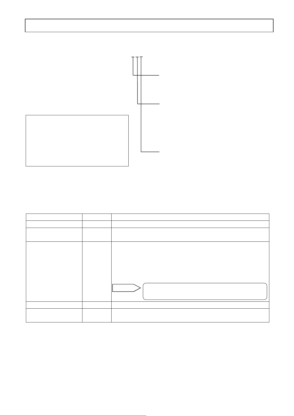
2. Symbols used in this manual
The following symbols are used depending on important degrees of warnings/cautions to
operate this product safely and to avoid malfunctions or unexpected situation.
Important
degree
Symbols Contents
1
2
3
4
5
Warning
Caution
Remarks
Reference
This symbol is indicated with a title for an explanation
with .
Indicates important information that must be observed to avoid
the risk of fire or electric shock or other dangers that may result
in serious personal injury or death, or damage to this product.
Indicates important information that must be observed to avoid
the risk of personal injury or malfunctions of this product.
Indicates supplementary information that the operator is
recommended to understand.
Indicates supplementary information or a reference to an
operation.
Warning
-Front2-
Page 4
INST.No.INE-477-P1CE Ver.1.00
Warnings and Cautions
!
Please observe the following safety precautions fully to use this product correctly. In addition,
please read this manual carefully and store it in a readily accessible location for future reference.
The mark indicates actions that are prohibited during an operation.
Warning (May cause death or serious personal injury)
Do not operate this product in a location where flammable or volatile gas is present.
The use of this product in such environment may result in the risk of explosion.
If this product emits any smoke, abnormal noise or unusual odor, immediately turn off power.
Do not continue to use this product as it may result in the risk of fire or electric shock. Turn
off the power source to this product and contact your nearest sales agent of CHINO
Corporation. Do not repair this product yourself as it may be dangerous.
Never touch the internal parts of this product.
If you touch the inside of this product, it may result in personal injury by electric circuits or a
moving part
Even when you open the case of this product for maintenance works, never touch the internal
parts.
Do not attempt to repair or modify this product.
Repairing or modification must be carried out by service personnel authorized by CHINO
Corporation.
If you repair or modify this product yourself, it may not fulfill this product’s functions, or it
may result in the risk of electric shock or damage to this product.
Do not touch, with wet hands, the power terminals or plugs of the power cord.
If you touch, with wet hands, the power terminals or plugs of the power cord, it may result in
the risk of electric shock.
If you notice something suspicious, immediately turn off power.
If the temperature of the power cord or other cable is high abnormally, turn off the power
source to this product immediately and contact your nearest sales agent of CHINO
Corporation.
Confirm the grounding.
To avoid the risk of electric shock, before supplying the power to this product, make sure that the
power terminals and the protective ground terminal have been wired correctly and reliably.
Caution (May cause personal injury or property damage )
Confirm the specifications (Model code) of this product.
Before using this product, check that the model code shown in the serial number plate matches your
order.
Separate precautionary safety measures should be provided before using this product.
When this product is used in equipment that needs security measures, provide separate safety
measures with the equipment before using this product, responding to phenomena resulting from
erroneous operations or malfunctions of this product or malfunctions of related instruments.
Use crimp type lugs for termination of wires.
To avoid dropping-out or short-circuit of wires, use crimp type lugs for their termination.
Confirm the power to this product.
Before supplying the power to this product, make sure that the power voltage matches the rated
voltage to this product and that the power terminals and the protective ground terminal have been
wired correctly and reliably.
Do not continue to use this product remaining malfunctioned.
Do not continue to use this product remaining malfunctioned as it may result in the risk of fire
or electric shock. Contact your nearest sales agent of CHINO Corporation for repairing.
Comply with the descriptions in this manual.
Comply with the descriptions and handling instructions in this manual to ensure that you use this
product correctly and safely.
Failure to comply with the descriptions and instructions may result in damage to or functional decline
of this product or damage to the equipment.
-Front3-
Page 5
INST.No.INE-477-P1CE Version 1.00
Contents
1. Introduction ··························································1
1.1 General·························································· 1
1.2 Configuration················································1
2. Models and accessories ········································2
2.1 Models ·························································· 2
2.2 Attachments ·················································· 2
3. Installation and connections································3
3.1 Setting dipswitches ······································· 3
3.1.1 How to pull out the internal unit···················3
3.1.1-1) For this unit not installed on a panel ········· 3
3.1.1-2) For this unit being installed on a panel ·····3
3.1.2 Setting dipswitches ······································· 4
3.2 Installation ···················································· 5
3.2.1 Dimensions and panel cutout························5
3.2.2 How to install················································ 5
3.3 Connections ·················································· 6
3.3.1 Enlarge view of the terminal board················ 7
3.3.2 Communication output terminals··················· 7
3.3.3 Contact input terminals··································7
3.4 Cautions on connections······························· 8
3.5 Analog output and alarm output ················· 9
3.6 Multiple-detector units connection ············· 10
3.6.1 Relaying boxes used ··································· 10
3.6.2 Relaying boxes not used ····························· 10
!
!
!
5.3.1-2)
5.3.2 Setting procedure········································ 16
5.3.2-1)
5.3.2-2)
5.3.2-3) Setting from (4) correction coefficients
5.3.3 Correcting calibration curves······················· 18
5.4 Setting output limit values of
5.4.1 Data for setting limit values of calibration
curves········· 19
5.4.2 Procedure for setting the data for output limit
5.4.2-1)
5.4.2-2) Enabling/disabling the output limit
5.4.2-3) Setting a low limit absorbance value (XL)
Descriptions of the setting data for
calibration curves································ 15
Setting detector unit numbers and (1)
calibration curve numbers to (3)
calibration curve coefficients for
IRMA1000, 2000, 7000 or 8000 series
detector units ······································· 16
Setting detector unit numbers and (1)
calibration curve numbers ~ (3)
calibration curve coefficients for
IRMA5000 or 6000 series detector units
being connected··································· 17
b
~ b2 to (8) water absorbance ············ 18
0
calibration curves················· 19
values of calibration curves················· 20
Setting calibration curve numbers (CH) 20
processing (LM)·································· 20
and a low limit measured value (YL)······ 20
4. Names and functions···········································11
4.1 Names and functions of
displays, lamps and keys····················· 11
5. Operation·····························································13
5.1 Confirmation before operation ··················· 13
5.2 Setting detector unit numbers ····················· 13
5.3 Setting calibration curves ···························14
5.3.1 Data for setting ··········································· 14
5.3.1-1) List of data for setting calibration curves 14
- C1 -
5.4.2-4) Setting a high limit absorbance value (XH)
and a high limit measured value (YH)····· 21
5.4.2-5) Setting output limit values to other
calibration curve numbers ··················· 21
5.5 Selecting calibration curve numbers··········· 22
5.5.1 Selecting calibration curve numbers for
IRMA1000, 2000, 7000 or 8000 series
detector units ······································· 22
5.5.2
Selecting calibration curve numbers for
IRMA5000 or 6000 series detector units 22
Page 6

INST.No.INE-477-P1CE Version 1.00
5.6 Setting operation conditions I
(display/output)······································· 23
5.6.1 List of setting data ··········································· 23
5.6.2 Setting operation conditions·························· 23
5.6.2-1) Time constant ··············································· 23
5.6.2-2) Smoothing/real············································· 23
5.6.2-3) Hold ······························································· 23
5.6.2-4) Preset output················································· 23
5.7 Setting operation conditions II
(MODE setting)······································ 24
5.7.1 List of data for setting operation conditions II· 24
5.7.2 Weight α, calibration constant······················· 26
5.7.3 Decimal place displaying measured values 26
5.7.4 Calibration curve remote contact inputs with
Binary or BCD ········································ 26
5.7.5 Sample temperature correction enabled or
disabled····················································· 27
5.7.6 Sample temperature displaying ····················· 27
5.7.7 Sample temperature input scaling ················ 27
5.7.8 Displaying constituent numbers ··················· 27
5.7.9 Selecting a constituent number for an analog
output and a contact output from a
detector unit ·············································· 28
5.7.10 Selecting a contact output from a
detector unit enabled or disabled and
an output item············································ 28
Contents
5.8.4 Hold ···························································· 30
5.9 Key lock ····················································· 30
5.10 Calibration (For performing a calibration,
read the paragraph [Calibration] in a
separate instruction manual for a
detector unit being connected, too.) ···· 31
5.10.1 Calibration for IRMA1000, 2000, 7000 or
8000 series detector units···················· 31
5.10.2 Calibration for IRMA5000 or 6000 series
detector units······································· 32
6. Creating calibration curves································33
6.1 Sample preparation····································· 33
6.2 Sample measurement·································· 33
6.3 Creating calibration curves························· 33
7. Inspection and maintenance ······························34
7.1 Periodical inspection ·································· 34
7.2 Self-diagnosis function······························· 34
7.3 Measures against troubles not included
with self-diagnosis······························ 35
7.3.1 Measured value remains unchanged··········· 35
7.3.2 Measured value fluctuates ·························· 35
7.3.3 Measured value is slightly higher or
lower than the actual value ················· 35
7.4 Maintenance parts······································· 35
7.5 RAM clearing ············································· 35
5.7.11 Selecting a contact input to a detector unit
enabled/disabled and an input item·········· 28
5.7.12 Displaying a calibration curve number ······ 28
5.7.13 Computing surface water ratio····················· 28
5.7.14 Setting communication conditions·············· 29
5.8 Remote contact inputs ·····································30
5.8.1 Setting detector unit numbers, constituent
numbers and calibration curve numbers ······30
5.8.2 Calibration··································································30
5.8.3 Preset············································································30
- C2 -
8. Specifications ·······················································36
8.1 Operator interface/display unit:
IRGMEG2 ······································ 36
8.2 Outside dimensions ···································· 36
Page 7
INST.No.INE-477-P1CE Ver.1.00
1. Introduction
1.1 General
The infrared multiple-constituents analyzer (hereinafter called “constituent meter”) operator
interface/display unit IR-GMEG2 is used in combination with IRMA series constituent
meter detector units and can communicate with up to nine (9) detector units.
The operator interface/display unit digitally displays constituent values including moisture content and
thickness, as well as accessing to parameters of a detector unit. It also provides various functions
including communication and calibration curve switching by a contact signal.
This manual describes about the operator interface/display unit only. In addition to this manual, refer
to a separate instruction manual of [Infrared multiple-constituents analyzer detector unit
IRMA], too.
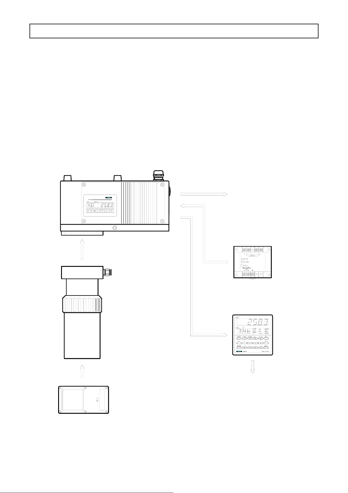
1.2 Configuration
Detector unit
IRMA11, 12, 13
IM
SERIES
(Configuration example in combination with IRMA1)
Analog output
Power unit IR-WEP
(Supplied as an
attachment)
24V DC
Connection cable
IR-WERP
Operator interface
Air-purge hood
IR-WEA
/display unit
IRGMEG2
RS-485
Output checker plate
IR-WEB
(Note) In case of using IRMA data logging software Model for IM-VXA
personal computer and detector unit are a direct communication.
- 1 -
Communication output (Note)
Analog output
, the
Page 8
INST.No.INE-477-P1CE Ver.1.00
)
2. Models and accessories
2.1 Models
IRGMEG2
Operator interface/display unit for
constituent meters Output
2: 4 to 20mA
Communication interface
R: RS-232C (standard)
CE
(Standards)
• EN55011 Group 1 Class A
• EN50082-2 (Industrial environment)
(Directives)
89/366/EEC, 92/31/EEC (amendment)
93/68/EEC (amendment
A: RS-422A
S : RS-485
*In case of connecting with
IM-VXA it is RS-232C.
Special specifications
Blank: Standard
V : Complying with CE
2.2 Attachments
Name Quantity Remarks
Mounting brackets 1 set
Internal unit
pulling-out tool
Ferrite core 3 pieces Attached only for complying with CE
Instruction manual 1 copy This document
Instruction manual for
communications
1 piece
1 piece for the cable IR-WERP
1 piece for a power cable
1 piece for a signal cable
(Refer to [3.3 Connections] and [3.3.1 Enlarge view of the
terminal board] )
Remarks
When 4 pieces of ferrite cores or more are
required, order them separately.
1 copy Separate m anual “ IM series I R MA/IRGMEG2 Communications”
- 2 -
Page 9
INST.No.INE-477-P1CE Ver.1.00
p
3. Installation and connections
3.1 Setting dipswitches
!
Set internal dispswitches before installing this unit.
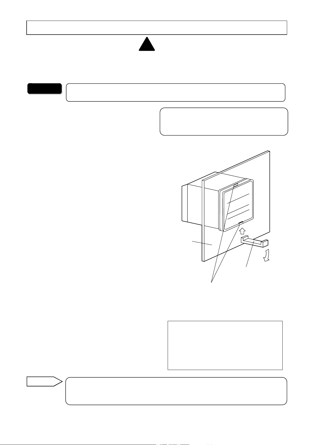
3.1.1 How to pull out the internal unit.
Warning
3.1.1-1) For this u n i t n o t i n s t a l l e d o n a p a n e l
(1) Remove the water-proof gaskets fitted in the
locking portions of the internal unit. Hold this
unit and then insert the L-shaped part of the
supplied pulling-out tool into the lower
locking portion of this unit.
(2) In this state, press the other side of the tool
down to slide the front panel forward 2 to
3mm and then remove the internal unit. (*)
(3) After setting the dipswitches, position the
printed circuit boards of the internal unit with
the guide rails on the inside of the case and
push the internal unit slowly along the guides
until it is locked. Make sure to press the
water-proof gaskets in the locking portions
securely. (Note)
3.1.1-2) For this unit being installed on a panel
For avoiding the risk of electric shock, make sure to turn off the power source to
this unit before pulling out the internal unit.
The front panel of this unit complies with IP65
(IEC529). For this compliance, it may be hard to pull
out the internal unit.
①
Panel
(1) Remove the water-proof gaskets fitted in the
locking portions of the internal unit. Insert
the L-shaped part of the supplied pulling-out
tool for the internal unit into the locking
portion on the lower side of this unit.
(2) In this state, press the other side of the tool
down to slide the front panel forward 2 to
3mm and then remove the internal unit. (*)
(3) After setting the dipswitches, position the
printed circuit boards of the internal unit with
the guide rails on the inside of the case and
push the internal unit slowly along the guides
until the locking portion is activated. Make
sure to press the water-proof gaskets in the
locking portions securely. (Note)
Remarks
(*): Ordinarily the internal unit can be pulled out by only loosening the lower
locking portion of this unit. However, if it is hard to remove it, loosen the upper
locking portion, too.
②
Internal unit pulling-out tool
Internal unit locking portion
(The water-proof gasket is fitted in.)
(Note)
When this unit is used in the state that the
locking portion is not activated, it may cause
display fluctuation by contact failure of
terminal metals. In addition, the
effectiveness of water-proofing may become
aired.
im
- 3 -
Page 10
INST.No.INE-477-P1CE Ver.1.00
3. Installation and connections
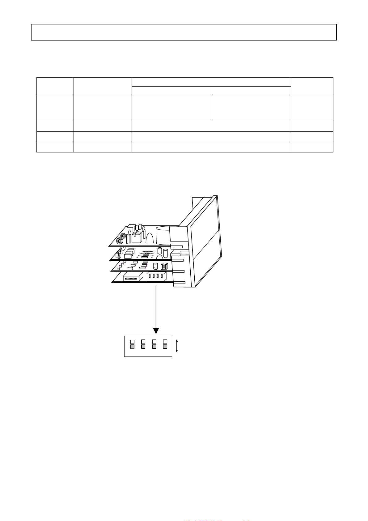
3.1.2 Setting dipswitches
Set the dipswitches depending on the quantity of the detector units to be connected.
Position of dipswiches Dipswitch
OFF ON
No.
1
Function
Quantity of the
detector unit to be
connected
1 set
(Single-detector-unit
connection)
2 Not used Not used (remaining at OFF)
3
4
Not used
Not used
Not used (remaining at OFF)
Not used (remaining at OFF)
[Internal unit pulled out]
1234
[Enlarged view of dipswitches]
OFF
1234
ON
2 sets or more
(Multiple-detector-units
connection)
Default
settings
OFF
OFF
OFF
OFF
- 4 -
Page 11
INST.No.INE-477-P1CE Ver.1.00
n
j
r
t
3. Installation and connections
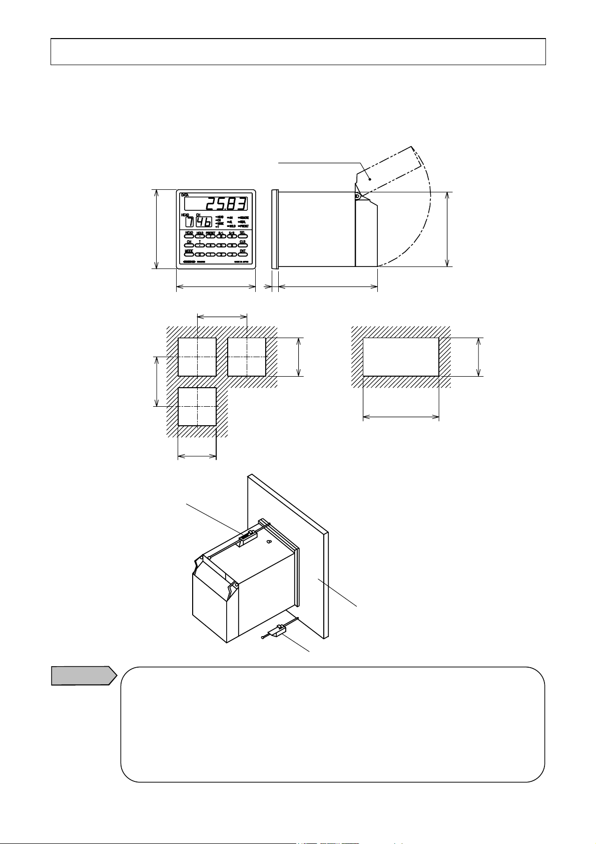
3.2 Installation
This unit is designed to be installed on a panel (instrumentation panel).
Set the supplied mounting brackets (2 pieces) in place on the top and bottom of this unit, and then
tighten the screws of the brackets until they turn free.
3.2.1 Dimensions and panel cutout
96
96
120
120
92
+0.8
0
3.2.2 How to install
Caution
Mounting bracket
Do not install this product in the following locations.
• Locations filled with dusts or corrosive gas.
• Locations where the ambient temperature is higher than 50 ºC or lower than 0 ºC, or widely
changing.
• Very humid locations
• Close to power lines or locations disturbed by strong magnetic induction
• Locatio
s sub
ected to vibrations or shocks
Terminal cove
8
0
+0.8
92
Mounting bracke
120
Panel
96×N−4
0
‑1
0
‑1
□91 ×91
0
+0.8
92
0
‑2
Unit : mm
- 5 -
Page 12
INST.No.INE-477-P1CE Ver.1.00
g
(
(
)
(
)
3. Installation and connections
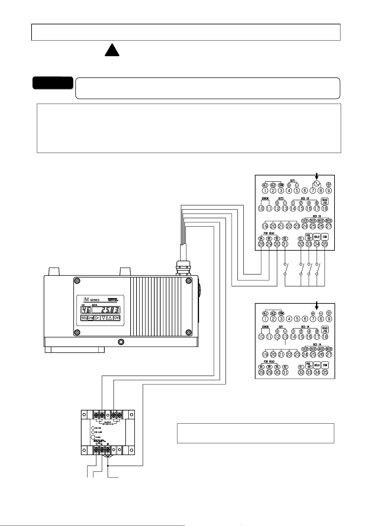
3.3 Connections
!
Wire to the terminals on the rear of this unit as shown in the following terminal wiring diagrams.
Before carrying out wiring, turn off the power source to this unit.
Warning
For avoiding the risk of electric shock, make sure to turn off the power source to this
unit before wiring to the power terminals.
For complying with CE (IRGMEG2V)
1) Attach the supplied ferrite cores (3 pieces attached as standard), at a place as close as the
terminal board (within 10cm), to bind up each cable to be connected. (→For the details of
attaching ferrite cores, refer to [3.3.1 Enlarge view of the terminal board].)
2) The connection cable should be used indoors and its length should be up to 30m.
[ IRGMEG2 ]
Contact rating
Resistive load
100V AC 0.5A
200V AC 0.2A
Inductive load
100V AC 0.2A
200V AC 0.1A
Minimum load
5V DC 10mA
[ IRGMEG2V ]
Contact rating
Resistive load
30V AC 0.5A
24V DC 0.2A
Inductive load
30V AC 0.2A
24V DC 0.1A
Minimum load
5V DC 10mA
Cable
IR-WERP
Operator interface/display unit
[IRGMEG2]
Comm output
Note
Detector unit
IRMA
[IRGMEG2V]
Note
Power 24V DC
P- (Blue)
Red)
P+
G (Green)
Comm output
Power unit
IR-WEP
(Note) 100-240V AC for IRGMEG2
24V DC for IRGMEG2V (complying with CE)
100-120V AC
200-240V AC
Protective
round
- 6 -
Page 13
INST.No.INE-477-P1CE Ver.1.00
)
)
3. Installation and connections
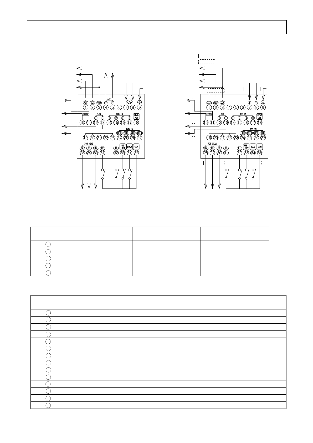
3.3.1 Enlarge view of the terminal board
*1 : Refer to [3.4 Cautions on connections] (3) Power
*2 : Refer to [3.5 Analog output and alarm output]
Output 1 (*2)
AL2 low alarm output (*2)
AL1 high alarm output (*2)
Self-diagnosed (*2)
abnormal
Alarm output Contact (*2
OFF when an
abnormal condition
occurs.
Output 2 (*2)
4 to 20mA DC
SA (black)
To the
detector unit
4 to 20mA DC
Comm output
SB (white)
SG (brown)
Contact input
IRGMEG2
Power (*1)
100 to 240V AC
Protective
ground
AL2 low alarm output (*2)
AL1 high alarm output (*2)
Self-diagnosed (*2)
abnormal
Alarm output Contact (*2
OFF when an
abnormal condition
occurs.
Output 1 (*2)
4 to 20mA DC
(Note) If 4 pieces or more are required, order them separately.
Example of attaching places of ferrite cores
(3 pieces attached as standard)
: To be attached absolutely
: At any place (Note)
Power (*1)
24V DC
Protective
ground
Comm output
To the
detector unit
Contact input
IRGMEG2V (complying with CE)
3.3.2 Communication output terminals
Terminal
No.
19
SD SDA SA
-- SDB SB
20
21
RD RDA --
22
-- RDB - SG SG SG
23
IRGMEG2R
RS-232C communication
IRGMEG2A
RS-422A communication
3.3.3 Contact input terminals
Terminal
No.
14
BCD IN 1 Detector unit No./Calibration curve No./Constituent No. 1-input
15
BCD IN 2 Detector unit No./Calibration curve No./Constituent No. 2-input
16
BCD IN 4 Detector unit No./Calibration curve No./Constituent No. 4-input
BCD IN 8 Detector unit No./Calibration curve No./Constituent No. 8-input
17
HEAD/CH Switching of the detector unit No. and the calibration curve No.
18
24
BCD IN 1 x 10 Detector unit No./Calibration curve No. 1 x 10-input
BCD IN 2 x 10 Detector unit No./Calibration curve No. 2 x 10-input
25
26
BCD IN 4 x 10 Detector unit No./Calibration curve No. 4 x 10-input
BCD IN 8 x 10 Detector unit No./Calibration curve No. 8 x 10-input
27
K2 Constituent No. input command
31
K1 No. 1 side calibration with the contact ON
32
PRESET Preset output with the contact ON
33
HOLD Hold with the contact ON
34
COM Common contact terminal
35
Item Explanation
IRGMEG2S
RS-485 communication
- 7 -
Page 14

INST.No.INE-477-P1CE Ver.1.00
g
3. Installation and connections
3.4 Cautions on connections
!
Warning
For avoiding the risk of electric shock, make sure to turn off the power source to this
unit before wiring to the power terminals.
Before carrying out wiring, observe the following precautions.
(1) Terminating wires
Use crimp type lugs covered with the insulation sleeve to prevent wires from dropping off or contacts
of wires. (The terminal screws are M3.5.)
(2) Mounting a power switch and a fuse
Neither power supply nor fuse is built in this unit. You are required to prepare them separately.
(3) Power
[IRGMEG2]
• The power to IRGMEG2 is universal from 100 to 240V AC but avoid the following powers;
(1) Powers whose voltage fluctuates greatly.
(2) Powers whose waveform distortion is big.
[IRGMEG2V (complying with CE)]
• The power to IRGMEG2 V (complying with CE) is 24V DC (within ±10%).
Ordinarily supply the power to this unit from the power unit IR-WEP.
Caution
The power to IRGMEG2 V (complying with CE) is DC.
Observe the following cautions.
1) Ensure correct polarity.
2) The connection with reverse polarity may cause a failure of this unit.
3) Make sure not to supply AC power to this unit. If AC power is supplied by mistake, this unit
will be dama
ed.
(4) Noise source
Separate this unit from strong power circuits or powerful noise sources as far as possible.
- 8 -
Page 15

INST.No.INE-477-P1CE Ver.1.00
3. Installation and connections
3.5 Analog output and alarm output
This unit is designed for use with multiple-constituents analyzer detector units connection and can
connect plural constituent meter detector units.
However, the analog outputs and alarm outputs are configured by setting the dipswitches as shown
below. (Refer to [3.1 Setting dipswitches].)
Position of the dipswitch No. 1: OFF Position of the dipswitch No. 1: ON
Item
Connected
detector
OUT1 Analog output from the
OUT2 (*) Analog output from the
AL1 High limit alarm signal
AL2 Low limit alarm signal
ERROR Self-diagnosed abnormal
(*) Available in IRGMEG2 only [OUT 2 is not available in IRGMEG2V (complying with CE).]
Detector unit: 1 set(Single-detector-unit connection) Detector unit: 2 sets or more
(Multiple-detector-units connection)
IRMA1000,2000,
7000,8000 series
1 constituent specification
2 or more constituents
specification of
IRMA5000,6000 series
IRMA1000,2000,7000,8000 series
IRMA5000,6000 series
of IRMA5000,6000 series
constituents No. 1 of
detector unit No. 1
constituents No. 1 of
detector unit No. 1
from the detector unit No. 1
from the detector unit No. 1
condition signal from the
detector unit No. 1
Analog output from the
constituents No. 1 of
detector unit No. 1
Analog output from the
constituents No. 2 of
detector unit No. 1
High limit alarm signal
from the detector unit No. 1
Low limit alarm signal
from the detector unit No. 1
Self-diagnosed abnormal
condition signal from the
detector unit No. 1
Analog output from the constituents
No. 1 of detector unit No. 1
Analog output from the constituents
No. 1 of detector unit No. 2
High limit alarm signal from the
detector unit No. 1
Low limit alarm signal from the
detector unit No. 1
Self-diagnosed abnormal condition
signal from all detector units connected
- 9 -
Page 16

INST.No.INE-477-P1CE Ver.1.00
3. Installation and connections
3.6 Multiple-detector-units connection
In the multiple-detector-units connection, the following two connection systems are available. For
either connection system, before turning on the power to this unit, set detector unit numbers not to
overlap them each other.
For the settings of detector unit numbers, refer to the separate manual for a detector unit.
3.6.1 Relaying boxes used
Remarks
Caution
3.6.2 Relaying boxes not used
Remarks
Detector unit
IRMA
IM
SERIES
IM
SERIES
IM
SERIES
Cable
IR-WERP *
Cable
IR-WERP *
Cable
IR-WERP *
24V DC (Note)
Operator interface/
display unit
IRGMEG2
Relaying box
IR-WEE
(The power unit is built in.)
2-conductor twisted cable
(with shield)
2-conductor twisted cable
(with shield)
2-conductor twisted cable
(with shield)
100-240V AC
(Note): 24V DC at CE marking (In case of using IRGMEG2V)
(*): The connection cable should be indoors and its length should be up to 30m.
・For wiring to the relaying box, refer to the separate manual for the relaying box.
Detector unit
IRMA
IM
SERIES
IM
SERIES
IM
SERIES
Cable
IR-WERP *
Cable
IR-WERP *
Cable
IR-WERP *
Operator interface/
display unit
IRGMEG2
Power unit IR-WEP
-V +V
OUTPUT
DC24V2.1A
DCON
DCLOW
V.ADJ
INPUT50/60Hz
AC100-240V1.3A
-V +V
OUTPUT
DC24V2.1A
DCON
DCLOW
V.ADJ
INPUT50/60Hz
AC100-240V1.3A
-V +V
OUTPUT
DC24V2.1A
DCON
DCLOW
V.ADJ
INPUT50/60Hz
AC100-240V1.3A
24V DC (Note)
100-240V AC
(Note): 24V DC at CE marking (In case of using IRGMEG2V)
(*): The connection cable should be indoors and its length should be up to 30m.
- 10 -
Page 17

INST.No.INE-477-P1CE Ver.1.00
4.各部の名称と機能4. Names and Functions
4.1 Names and functions of displays, lamps and keys
(1) Data display
DATA
(4) Setting status
lamps
(2) Detector unit
number display
(3) Calibration curve
number display
HEAD CH
HEAD
MODE
HOLD
CH
HEAD
CH
MODE
T
PRESET
T
R/L
AH
AL
HOLD
S/R
REMOTE
REAL
PRESET
SEL
CLR
ENT
(5) Measurement
status lamps
(6) Key-lock
indicator
(7) Function keys
IRGMEG2
MADE IN JAPAN
Name Function
(1) Data display Displays a constituent value in the measurement mode and a parameter data in
the setting mode.
When a self-diagnosed abnormal condition is occurred, an error number
corresponding to an abnormal condition is displayed.
(2) Detector unit number
display
Displays a detector unit number of the constituent meter currently indicating a
constituent value in the data display. When the detector unit number is
changed, a constituent value being measured by the detector unit with the
changed number will be displayed.
(3) Calibration curve display
Displays a calibration curve number in the measurement mode, the calibration
curve setting mode, a mode number during the mode setting, and a time
constant during the time constant setting.
The first-digit decimal point indicates the key-lock activated.
(4) Setting status lamps HEAD: Lights during the detector unit number setting.
CH: Lights during the calibration curve number setting.
MODE: Lights during the mode number setting.
For IRMA5000 or 6000 series detector units being connected,
this lamp lights during the setting of the constituent number whose
calibration curve or time constant is set.
T: Lights during the time constant setting.
(5) Measurement status lamps AH: Lights when a high limit alarm is activated.
AL: Lights when a low limit alarm is activated.
HOLD: Lights in the hold mode.
REMOTE: Lights during the remote setting of a calibration curve number.
REAL: Lights during the real (without smoothing) measurement mode.
PRESET: Lights during the preset output.
(6) Key-lock indicator The first-digit decimal point indicates the key-lock activated.
- 11 -
Page 18

INST.No.INE-477-P1CE Ver.1.00
4.各部の名称と機能4. Names and Functions
4.1 Names and functions of displays, lamps and keys
Name Function
HEAD
CH
DATA
HEAD
CH
MODE
CH
HOLD
T
IRGMEG2
HEAD
CH
MODE
T
PRESET R / L
HEAD
Is used to set a detector unit number.
Is used to set a calibration curve number.
AHALREMOTE
REAL
PRESET
HOLD
SEL
S/R
CLR
ENT
MADE IN JAPAN
(7) Function keys
(7) Function keys
MODE
HOLD
PRESET
0
―
7
R/L
8
S/R
9
T
•
〜
SEL
CLR
ENT
6
Is used to set a mode number.
Switches the HOLD to ON or OFF in the measurement mode.
Is used to enter (―) in the setting mode.
Switches the PRESET to ON or OFF in the measurement mode.
Is used to enter the numeric of 7 in the setting mode.
Switches the calibration curve setting to REMOTE or LOCAL in the
measurement mode.
Is used to enter the numeric of 8 in the setting mode.
Switches the measurement mode to REAL or SMOOTHING in the
measurement mode.
Is used to enter the numeric of 9 in the setting mode.
Is used to set the time constant in the measurement mode.
Is used to enter the decimal point in the setting mode.
Is used to enter the numeric from 0 to 6 in the setting mode.
Is used to enter into the setting mode or switch setting screens.
Is used to clear a data being set.
A data is cleared from the least significant digit, each time this key is pressed
once.
Is used to store a parameter data.
- 12 -
Page 19

INST.No.INE-477-P1CE Ver.1.00
)
5
. Operation
5.1 Confirmation before operation
Check the following three points before turning on the power.
1) Have the dipswitches been set? (Refer to [3.1 Setting dipswitches].)
2) Are all of connections correct? (Refer to [3.3 Connections])
3) In the multiple-detector-units connection, have detector unit numbers been set?
(Refer to the separate instruction manual for [Infrared multiple-constituents analyzer detector unit
IRMA].)
Caution
Turn on the power to this unit concurrently with or after turning on the power to
detector units.
If the power to this unit is turned on before turning on detector units, this unit can
not recognize the detector units and will display the error code Er18 (detector unit
number error
.
5.2 Setting detector unit numbers
When the power to this unit is turned on, data
measured by the constituent meter with the detector
unit number being indicated in “HEAD” will be
displayed.
The following procedure is for changing a detector
unit number.
(1) Press HEAD key to enter into the detector unit
number setting mode with the setting lamp
“HEAD” lit.
(2) Press the numeric keys 1 to 9 to enter a detector
unit number.
(3) By pressing ENT key, the data measured by the
constituent meter with the changed detector unit
number will be displayed. The calibration curve
number and the constituent value displayed this
time are under the conditions set in the changed
constituent meter. (Time constant, decimal places
of constituent values displayed, etc.)
DATA
CH
HEAD
HOLD
HEAD
CH
T
MODE
IRGMEG2
HEAD CH DATA
PRESET
HEAD
CH
MODE
T
R/L
AHALREMOTE
REAL
PRESET
HOLD
SEL
S/R
CLR
ENT
MADE IN JAPAN
1 1 12.3
Detector unit No. Calibration curve No. Constituent value
HEAD CH DATA
2 12 54.32
Detector unit No.
The calibration
curve No.
changes, too.
The constituent
value changes,
too.
- 13 -
Page 20

INST.No.INE-477-P1CE Ver.1.00
5
b
. Operation
5.3 Setting calibration curves
Output characteristics of detector units depend upon measuring objects. It may also change according
to process conditions or constituent measuring conditions of samples.
Accordingly, for accurate measurements, it is required to perform beforehand sample tests of each
object and obtain, for moisture measurements, a relationship (This is called as a calibration curve.)
between moisture contents (%H2O) obtained by a drying method or other measuring methods and
absorbance “x” measured by a detector unit] or, for thickness measurements, a relationship (This is
called as a calibration curve.) between thickness (µm) obtained by a micrometer or other measuring
methods and absorbance “x” measured by a detector unit].
Reference
5.3.1 Data for setting
5.3.1-1) List of data for setting calibration curves
The followings are data for setting calibration curves.
Setting items available differ depending on specifications (number of wavelengths and number of
constituents) of a detector unit being connected.
Setting data name Display
(1) Calibration curve No. CH 1 to 99 1
(2) Computing mode Md 1 to 4 1 (*1)
Calibration curve coefficient a0 A0 0 to ±9999.9 0.0000
(3)
Calibration curve coefficient a1 A1 0 to ±9999.9 1.0000
Calibration curve coefficient a2 A2 0 to ±9999.9 0.0000
Calibration curve coefficient a3 A3 0 to ±9999.9 0.0000
The followings are used in the mode 4 only. The numeric from 4 to 10 indicates the number of wavelengths. (*1)
Calibration curve coefficient a4 A4 0 to ±9999.9 0.0000
Calibration curve coefficient a5 A5 0 to ±9999.9 0.0000
Calibration curve coefficient a6 A6 0 to ±9999.9 0.0000
Calibration curve coefficient a7 A7 0 to ±9999.9 0.0000
Calibration curve coefficient a8 A8 0 to ±9999.9 0.0000
Calibration curve coefficient a9 A9 0 to ±9999.9 0.0000
Calibration curve coefficient a
(4) Correction expression coefficient b0
Correction expression coefficient b
Correction expression coefficient b
High limit output
High limit alarm
(7) Preset value PS 0 to 9999.9 0.0000
(8) Water absorbance Ab 0 to ±9999.9 0.0000 Effective numeric: 5 digits (*2)
*1: Displays and settings of these items are only available for IRMA5000 or 6000 series detector
units being connected.
*2: For measuring the moisture content of sands, etc., the water absorbance is required to be set. The
display and the setting of this water absorbance are only enable when the surface water ratio
computation shown in [5.7.12 Computing surface water ratio] is set to ON.
This paragraph describes the setting method of calibration curve data, assuming
that calibration curves have been already created. When the calibration curves have
not been created yet, refer to the paragraph [Sample preparation] in the separate
instruction manual of the detector unit IRMA
Setting range
of data
AA 0 to ±9999.9 0.0000
10
b0 0 to ±9999.9 0.0000
1
b1 0 to ±9999.9 1.0000
2
b2 0 to ±9999.9 0.0000
Lo 0 to 9999.9 0.0000 (5) Low limit output
Hi 0 to 9999.9 100.00
AL 0 to 9999.9 0.0000 (6) Low limit alarm
AH 0 to 9999.9 100.00
Default value Remarks
eing connected.
Effective numeric: 5 digits
Effective numeric: 5 digits
Effective numeric: 5 digits
For IRMA1000,2000,7000,8000
-Specify the number of decimal
places.
For IRMA5000,6000
-Effective numeric : 5 digits
- 14 -
Page 21

INST.No.INE-477-P1CE Ver.1.00
5
. Operation
5.3.1-2) Descriptions of the setting data for calibration curves
Setting data name Function
(1) Calibration curve
number
(2) Computing mode (*) The computing modes selectable differ depending on specifications (number of wavelengths and
(3) Calibration curve
coefficient
to a
(*)
a
0
10
(4) Correction expression
coefficient b
to b2
0
(5) Low limit output
High limit output
(6) Low limit alarm
High limit alarm
(7) Preset value By setting the preset output to ON by key operations or through communications, the value being
(8) Water absorbance Decide a water absorbance to compute a surface water ratio for measuring moisture contents of
(*): Selectable computing modes differ depending on models of the constituent meter detector units.
Refer to the table shown below for your selection of a computing mode.
IRMA1 IRMA2 IRMA5 IRMA6 IRMA7 IRMA8
An optional number from 1 to 99 can be designated as a calibration curve. Ordinarily it is
designated sequentially from “1”.
number of constituents) of a detector unit being connected.
The computing modes 1 to 3 are 3-wavelength ratio processing (R1, S1 and R2) in each group in
the table shown below.
• Computing mode 1: 3-wavelength ratio processing (λ1, 2, 3) in Group 1
• Computing mode 2: 3-wavelength ratio processing (λ4, 5, 6) in Group 2
• Computing mode 3: 3-wavelength ratio processing (λ7, 8, 9) in Group 3
• Computing mode 4 is multiple regression computation using each wavelength. The number of
the wavelengths differs depending on specifications of the detector unit and up to 10
wavelengths are available.
Each computing expression of the calibration curve is shown in the next column.
Wavelength λ1 λ2 λ3 λ4 λ5 λ6 λ7 λ8 λ9 λ10
GROUP 1 GROUP 2 GROUP 3
Computing mode 1 R1 S1 R2
Computing mode 2 R1 S1 R2
Computing mode 3 R1 S1 R2
Computing mode 4 λ1 λ2 λ3 λ4 λ5 λ6 λ7 λ8 λ9 λ10
These coefficients are provided for the following computing expressions to compute a calibration
curve.
1) Computing mode 1, 2, 3
A calibration curve is computed by the cubic or lower-degree polynomial.
x3 + a2x2 + a1x + a0,
y = a
3
where, “y” is a measured value and “x” is an absorbance (data of constituent 0).
2) Computing mode 4
A calibration curve is computed by the multiple regression computation at each wavelength.
+ a1LOG(λ1) + a2LOG(λ2) + …………. + a10LOG(λ10)
y = a
0
Note that settable coefficients differ depending on number of wavelengths being used.
These coefficients are provided for the quadratic expression correction against a measured value “y”.
Assuming that a measured value after the correction be “Y”, we obtain “Y = b2y2+b1y + bo”.
These specify measured values at a low limit output and a high limit output on the analog output
scaling. The output is scaled to 4mA at the low limit measured value and 20mA at the high limit
measured value.
A low limit alarm is activated when a measured value is lower than a low limit alarm setpoint.
A high limit alarm is activated when a measured value is higher than a high limit alarm setpoint.
set as a preset value is displayed and outputted, regardless of measured values.
sands, etc.
The relation between a measured moisture content (%: mass basis moisture content), a surface
water ratio (%) and a water absorbance (%) is;
y Surface water ratio = (Moisture content – Water absorbance) / (1 + (Water absorbance / 100)
Computing mode 1
Computing mode 2
Computing mode 3
Computing mode 4
{ { { { { {
― ―
― ―
― ―
(2 constituents or more) (2 constituents or more)
(3 constituents or more) (3 constituents or more)
(2 constituents or more) (2 constituents or more)
- 15 -
― ―
― ―
― ―
Page 22

INST.No.INE-477-P1CE Ver.1.00
5
. Operation
5.3.2 Setting procedure
The setting procedures for (1) calibration curve numbers, (2) computing modes and (3) calibration
curve coefficients a0 to a
depending on specifications (number of wavelengths and number of constituents) of a detector unit
being connected.
The followings are these setting procedures.
5.3.2-1) Setting detector unit numbers and (1) calibration curve numbers to (3) calibration curve coefficients for IRMA1000, 2000, 7000 or 8000 series detector units
shown in [5.3.1-1) List of the setting data for calibration curves differ
10
1) Use the numeric keys 1 to 9 to set a detector unit
HEAD CH DATA
number.
HEAD xx ENT
2) Press SEL key for 2 seconds to display "CH" in
the CH display for entering into the calibration
curve number setting mode.
3) Use the numeric keys 1 to 9 to set a calibration
curve number.
11 1
HEAD CH DATA
1CH 1
Calibration curve
number setting mode
xx xx ENT
4) Press SEL key to display "A0" in the CH display
for entering into the calibration curve coefficient
a0 setting mode.
HEAD CH DATA
1 A0 0.0000
5) Use the numeric keys 1 to 9 to set a calibration
curve coefficient a0.
Setting data name Setting data
xx xx xx xx xx ENT
Reference
Press T/• key to enter a decimal point.
6) Press SEL key to display “A1" in the CH display for entering into the
calibration curve coefficient a1 setting mode.
HEAD CH DATA
Calibration
curve number
〜
7) Set a calibration curve coefficient a1 with the
same key operation.
8) Repeat 6) and 7) to set calibration curve
coefficients a2 to a3.
- 16 -
1 A3 0.0000
Setting data name Setting data
Page 23

INST.No.INE-477-P1CE Ver.1.00
5
. Operation
5.3.2-2) Setting detector unit numbers and (1) calibration curve numbers ~ (3) calibration curve
coefficients for IRMA5000 or 6000 series detector units being connected
1) Use the numeric keys 1 to 9 to set a detector unit
number.
HEAD xx ENT
HEAD CH DATA
11 1
HEAD CH DATA
2) Press SEL key for 2 seconds to display "CH" in
the CH display for entering into the calibration
curve number setting mode.
3) Use the numeric keys 1 to 9 to set a calibration
curve number.
xx xx ENT
4) Press SEL key to display "Md" in the CH
display for entering into the computing mode
selection.
5) Use the numeric keys 1 to 4 to set a computing
mode.
xx ENT
6) Press SEL key to display "A0" in the CH display
for entering into the calibration curve coefficient
a0 setting mode.
7) Use the numeric keys 1 to 9 to set a calibration
curve coefficient a0.
xx xx xx xx xx ENT
Reference
Press T/• key to enter a decimal point.
8) Press SEL key to display “A1" in the CH display
for entering into the calibration curve coefficient
a1 setting mode.
1CH 1
Calibration curve
number setting mode
HEAD CH DATA
Calibration
curve number
1Md 1
Setting data name Setting data
HEAD CH DATA
1 A0 0.0000
Setting data name Setting data
〜
HEAD CH DATA
1 AA 0.0000
9) Set a calibration curve coefficient a1 with the
same key operation. (Refer to. 7) )
10) Repeat 8) and 9) to set calibration curve
coefficients a2 to a10. (A2 to AA in the CH
display)
- 17 -
Setting data name Setting data
Page 24

INST.No.INE-477-P1CE Ver.1.00
5
. Operation
5.3.2-3) Setting from (4) correction coefficients b0 ~ b2 to (8) water absorbance
1) Press SEL to enter into the next data setting mode.
2) Set from (4) correction coefficients b0 ~ b2 to (4) water absorbance with the same key operation as
the above [5.3.2.-2].
5.3.3 Correcting calibration curves
If an actual constituent value (moisture content or thickness) does not correspond with a constituent
value (moisture content or thickness) on a calibration curve being preset due to the difference of
one-line and off-line measurements, or other causes, correct it with correction coefficients b0, b1 and
b2. These coefficients are provided for the quadratic expression correction against a measured value
“y”. Assuming that a measured value after correction be “Y”, we obtain,
Y = b2y2 + b1y + bo
Usually, a shift correction is done with b0 only. (b1 = 1, b2 = 0)
Remarks
[Example 1]
[Example 2]
When a measured moisture content before correction is 15 (%H
actual moisture content is 13 (%H
= 0, b1 = 1, b0 = -2)
(b
2
When a measured thickness before correction is 25 (µm) and an actual
thickness is 23.5 (µm), “-1.5µm should be set.
(b
= 0, b1 = 1, b0 = -1.5)
2
O), “-2%H2O should be set.
2
O) and an
2
- 18 -
Page 25

INST.No.INE-477-P1CE Ver.1.00
5
. Operation
5.4 Setting output limit values of calibration curves
A measured value can be fixed by low limit and high limit absorbance values.
When an absorbance becomes less than a low limit
absorbance value, a measured value is fixed to YL
as shown right.
Also, when an absorbance becomes more than a
high limit absorbance value, a measured value is
fixed to YH.
5.4.1 Data for setting limit values of calibration curves
The followings are data for setting calibration curve output limit values.
Setting data name Display Setting range
of data
(1) Calibration curve number CH 1 to 99 1
(2) Output limit processing
enabled/disabled
Low limit absorbance value XL 0 to ±9999.9 0.0000 Effective numeric: 5 digits
(3)
Low limit measured value YL 0 to ±9999.9 0.0000 Effective numeric: 5 digits
High limit absorbance value XH 0 to ±9999.9 9.9999 Effective numeric: 5 digits
(4)
High limit measured value YH 0 to ±9999.9 9999.9 Effective numeric: 5 digits
Setting data name Description
(1) Calibration curve number Any calibration curve number in 1 to 99 can be specified,
(2) Output limit processing enabled/
disabled
(3) Low limit absorbance value XL
Low limit measured value YL
(4) High limit absorbance value XH
High limit measured value YH
LM OFF (disabled),
ON (enabled)
but it is normally specified from 1 sequentially.
Set the output limit processing enabled or disabled.
When ON (enabled) is set, a measured value is outputted
corresponding to limit values being set.
When OFF (disabled) is set, a measured value is
outputted corresponding to data of a calibration curve.
Enter data to fix a measured value at a low limit side.
Enter data to fix a measured value at a high limit side.
YH
YL
Measured
value
0
XL
Default
Absorbance
Remarks
value
OFF 0: OFF, 1: ON
XH
- 19 -
Page 26

INST.No.INE-477-P1CE Ver.1.00
5
. Operation
5.4.2 Procedure for setting the data for output limit values of calibration curves
5.4.2-1) Setting calibration curve numbers (CH)
1) Use the numeric keys 1 to 9 to set a detector unit
number.
HEAD xx ENT
2) Press SEL key and CH key simultaneously for 2
seconds to display "CH" in the CH display for
entering into the calibration curve number setting
mode for the calibration curve output limit
values.
3) Use the numeric keys 1 to 9 to set a calibration
curve number.
xx xx ENT
5.4.2-2) Enabling/disabling the output limit processing (LM)
1) Press SEL key to display “LM" in the CH
display for entering into the output limit
processing enabled/disabled setting mode. Use
the numeric key 0 or 1 to set the processing
enabled or disabled.
Enter 0 for OFF (disabled) and 1 for ON
(enabled).
xx ENT
5.4.2-3) Setting a low limit absorbance value (XL) and a low limit measured value (YL)
1) Press SEL key to display “XL" in the CH
display for entering into the low limit
absorbance value XL setting mode. Use the
numeric keys 0 to 9 to set a low limit
absorbance value XL.
Reference
Press T/• key to enter a decimal point.
2) Press SEL key to display “YL" in the CH
display for entering into the low limit measured
value YL setting mode. Use the numeric keys 0
to 9 to set a low limit measured value YL.
Reference
Press T/• key to enter a decimal point.
HEAD CH DATA
1CH 1
Calibration curve
number setting mode
HEAD CH DATA
Calibration
curve number
1LM OFF
Setting data name Setting data
HEAD CH DATA
1LM ON
Setting data name Setting data
HEAD CH DATA
1 XL 0.0
Setting data name Setting data
HEAD CH DATA
1 YL 0.0
Setting data name Setting data
- 20 -
Page 27

INST.No.INE-477-P1CE Ver.1.00
5
p
. Operation
5.4.2-4) Setting a high limit absorbance value (XH) and a high limit measured value (YH)
1) After the above settings [5.4.2-1)] to 5.4.2-3)],
press SEL key to display “XH" in the CH
display for entering into the high limit
absorbance value XH setting mode. Use the
numeric keys 0 to 9 to set a high limit
absorbance value XH.
Reference
Press T/• key to enter a decimal point.
2) After the above setting, press SEL key to display
“YH" in the CH display for entering into the high
limit measured value YH setting mode. Use the
numeric keys 0 to 9 to set a high limit measured
value YH.
Reference
Press T/• key to enter a decimal point.
5.4.2-5) Setting output limit values to other calibration curve numbers
HEAD CH DATA
1 XH 1.000
Setting data name Setting data
HEAD CH DATA
1 YH 50.0
Setting data name Setting data
1)After the above settings [5.4.2-1)] to 5.4.2-4)],
press SEL key to display “CH" in the CH display
for returning to the calibration curve number
setting mode.
2)Enter other calibration curve number for setting
output limit values.
3) Repeat the above procedure [5.4.2-1)] to
5.4.2-4)] to set output limit values to other
calibration curve numbers.
Remarks
After the above setting procedure is completed, return to the measurement mode
by pressing SEL key for two seconds, or the automatic return is made if no key is
ressed for one minute.
HEAD CH DATA
1CH 1
Calibration curve
number setting mode
Calibration
curve number
- 21 -
Page 28

INST.No.INE-477-P1CE Ver.1.00
5
. Operation
5.5 Selecting calibration curve numbers
DATA
This is for selecting a calibration curve number whose data
for computing moisture contents, thickness or constituent
values have been set in [5.3 Setting calibration curves].
5.5.1 Selecting calibration curve numbers for
IRMA1000, 2000, 7000 or 8000 series
detector units
1) Press CH key to light the setting status lamp “CH”.
2) Enter a calibration curve number by using the numeric
HEAD CH DATA
HEAD CH
HEAD
CH
MODE
HOLD
IRGM EG2
HEAD
AHALREMOTE
CH
MODE
T
PRESET
R/L
T
HOLD
S/R
MADE IN JAPAN
REAL
PRESET
SEL
CLR
ENT
keys 1 to 9 . After entering it, the setting status lamp
“CH” will go off and the mode will go to the
1 1 5.25
measurement mode.
[Going to the absorbance display mode]
Setting data name Setting data
HEAD CH DATA
By entering 0 in the calibration curve number selection and
pressing ENT key, the setting status lamp “CH” will go
off and the mode will go to the absorbance display mode.
1 2 7.12
HEAD CH DATA
1 0 0.0123
5.5.2 Selecting calibration curve numbers for IRMA5000 or 6000 series detector units
After selecting a constituent number you want to set, set a calibration curve number.
Settable constituent numbers differ depending on constituent specifications of a detector unit being
connected.
Data name Display Setting range Default value Remarks
Constituent number
Calibration curve number
C0
CH
[Changing constituent numbers]
1) Press CH key to light the setting status lamps “CH”
and “MODE”.
2) By entering a constituent number 1 to 4 by using the
numeric keys 1 to 4, “C1” to “C4” corresponding to
the constituent number entered will be displayed in
the CH display.
3) Press ENT key. The calibration curve number being
currently set will be displayed in the CH display and
the setting status lamp “MODE” will go off.
0 to 4 1 0: Absorbance display mode
1 to 99 1
HEAD CH DATA
1 C1 10.25
Setting data name Setting data
HEAD CH DATA
1 1 10.25
[Changing calibration curve numbers]
4) After the above settings, enter a calibration curve
number by using 1 to 9. After entering it, the setting
status lamp “CH” will go off and the mode will go to
the measurement mode.
5) For setting a calibration curve number for each
constituent number, repeat the above procedure.
[Going to the absorbance display mode]
When 0 is entered by using the numeric key 0 in the above
2) for entering a constituent number, “C0” is displayed in
the CH display. Then, by pressing ENT key, the setting
status lamps “MODE” and “CH” will go off and the mode
will go to the absorbance display mode.
- 22 -
HEAD CH DATA
1 2 5.25
HEAD CH DATA
1 C0 5.25
Page 29

INST.No.INE-477-P1CE Ver.1.00
5
. Operation
5.6 Setting operation conditions I (display/output)
This is for setting display/output conditions of a detector unit by this unit.
5.6.1 List of setting data
Setting data name Lamp Setting range of data Default value
(1) Time constant T lights.
(2) Smoothing/real
(3) Hold
Preset output
(4)
ON/OFF
REAL
lights.
HOLD
lights.
PRESET
lights.
0.1 to 9.9 (less than 10 sec)
1 to 99 (10 sec or more)
Smoothing/real switching
HOLD activated/released
ON/OFF
0.2
(T goes off.)
Smoothing
(REAL goes off.)
HOLD released
(HOLD goes off.)
OFF
(PRESET goes off.)
5.6.2 Setting operation conditions
5.6.2-1) Time constant
When a measured value fluctuates quickly, the signal can be dulled by delaying a response time of a
constituent meter detector unit. A smoothing time (equivalent to a time constant of analog
instruments) can be set with 0.1-second increment for shorter than 10 seconds and 1-second increment
for 10 seconds or longer.
DATA
HEAD CH
HEAD
CH
MODE
HOLD
IRGM EG2
HEAD
AHALREMOTE
CH
MODE
T
PRESET
R/L
T
HOLD
S/R
MADE IN JAPAN
REAL
PRESET
SEL
CLR
ENT
<For IRMA1000, 2000, 7000 or 8000 series detector units being connected>
1) Press T/• key to display the setting status lamp “T”.
HEAD CH DATA
2) Enter a time constant by using the numeric keys 0 to 9
and press ENT key. The setting status lamp “T” will go
1 0.2 10.25
off and the mode will return to the measurement mode.
<For IRMA5000 or 6000 series detector units being connected>
Setting data name Setting data
HEAD CH DATA
1) Press T/• key to display the setting status lamp
“MODE”.
1 1 10.25
2) Enter a constituent number for setting a time constant
by using the numeric keys 1 to 4 and press ENT key.
HEAD CH DATA
The setting status lamp “MODE” will go off and the
time constant being currently set will be displayed in
the CH display.
1 C1 10.25
HEAD CH DATA
3) Enter a time constant by using the numeric keys 0 to
9 and press ENT key. The setting status lamp “T”
will go off and the mode will return to the
measurement mode.
1 0.2 10.25
HEAD CH DATA
1 1 10.25
5.6.2-2)Smoothing/real
This is for switching the smoothing processing (The setting of time constant is effective.) of measured
values or the real processing (Time constant = 0.0 second) of them. The setting status lamp “REAL”
turns on to indicate the real processing. By pressing S/R/9 key, the processing becomes the smoothing
processing and the setting status lamp “REAL” will go off.
This setting will be reflected in analog outputs and displays.
5.6.2-3) Hold
This is used to hold a measured value.
1) By pressing HOLD/― key, a measured value will be held and an analog output will be held, too.
2) By pressing HOLD/― key again, the holding condition will be released.
In the holding condition, the setting status lamp “HOLD” will light.
5.6.2-4) Preset output
This is used to display the constituent value being set as a preset value. With the display of the preset constituent
value, an analog output corresponding to the preset constituent value will be outputted.
1) By pressing PRESET/7 key, the preset output will be activated.
2) By pressing PRESET/7 key again, the preset output will be released.
In the preset output condition, the setting status lamp “PRESET” will light.
- 23 -
Page 30

INST.No.INE-477-P1CE Ver.1.00
D
g
5
p
. Operation
5.7 Setting operation conditions II (MODE setting)
For setting various operation conditions of this unit and a detector unit, use the MODE setting.
The MODE setting is only available in the absorbance display mode.
Remarks
Caution
5.7.1 List of data for setting operation conditions II
The followings are data for setting operation conditions II.
Setting items available differ depending on number of constituents.
MODE
No.
6
14
17
19
20
21
*1: (1) Weight α1: The 3-wavelength processing and the 2-wavelength processing can be changed by setting the weight α1.
*2: (1) Weight α2: The 3-wavelength processing and the 2-wavelength processing can be changed by setting the weight α2.
*3: (1) Weight α3: The 3-wavelength processing and the 2-wavelength processing can be changed by setting the weight α1.
Setting data name
Weight α, Calibration constant
Computation
mode 1
Computation
mode 2
Computation
mode 3
Decimal place displaying
measured values
Calibration curve remote inputs
with Binary or BCD
Sample temperature correction
enabled or disabled
(For detector units for 1
constituent in IRMA series)
Sample temperature displaying
Sample temperature input scaling Lo, Hi Lo
When α1 is set to 0.5, the processing becomes the 3-wavelength processing that is the ratio processing of three
wavelengths.
When α1 is set to 0 or 1, the processing becomes the 2-wavelength processing.
(α1: 1 - the ratio processing of λ1 and λ2, α1: 0 - the ratio processing of λ2 and λ3)
(2) Calibration constant k1: This constant is automatically obtained in [5.10 Calibration].
When α1 is set to 0.5, the processing becomes the 3-wavelength processing that is the ratio processing of three
wavelengths.
When α1 is set to 0 or 1, the processing becomes the 2-wavelength processing.
(α1: 1 - the ratio processing of λ1 and λ2, α1: 0 - the ratio processing of λ2 and λ3)
(2) Calibration constant k2: This constant is automatically obtained in [5.10 Calibration].
When α1 is set to 0.5, the processing becomes the 3-wavelength processing that is the ratio processing of three
wavelengths.
When α1 is set to 0 or 1, the processing becomes the 2-wavelength processing.
(α1: 1 - the ratio processing of λ1 and λ2, α1: 0 - the ratio processing of λ2 and λ3)
(2) Calibration constant k3: This constant is automatically obtained in [5.10 Calibration].
For exiting the MODE setting, press SEL key for 2 seconds or the automatic return to the
measurement mode is made if no key is pressed for one minute.
If an invalid MODE number is entered, “Er” will be displayed in the CH display.
After one second, the automatic return to the measurement mode is made if no key is
ressed for one minute.
Settin
isp.
Weight α1 1A*10 to 1.000 0.500
Calibration constant K1 1K
Weight α2 2A*20 to 1.000 0.500
Calibration constant K2 2K
Weight α3 3A*30 to 1.000 0.500
Calibration constant K3 3K
*1
*2
*3
d□ 0 to 4 1
0, 1 0
0, 1 0
range
of data
0 to ±9.9999 1.0000
0 to ±9.9999 1.0000
0 to ±9.9999 1.0000
Default
value
Remarks
0.5: 3-wavelength processing
0 or 1: 2-wavelength processing
0.5: 3-wavelength processing
0 or 1: 2-wavelength processing
0.5: 3-wavelength processing
0 or 1: 2-wavelength processing
0: Not displays after the decimal point
1: Displays 1 decimal place
2: Displays 2 decimal places
3: Displays 3 decimal places
4: Displays 4 decimal places
0: Binary
1: BCD
0: Disable
1: Enable
When 1(enable) is selected in Mode
19, this mode is effective
Lo: Analog input scaling low limit value
Hi: Analog input scaling high limit value
Para.
5.7.2
5.7.3
5.7.4
5.7.5
5.7.6
5.7.7
- 24 -
Page 31

INST.No.INE-477-P1CE Ver.1.00
D
g
5
. Operation
MODE
No.
30
31
32
33
35
40
80
Setting data name
Displaying a constituent number
(For IRMA5000 or 6000 series
detector units only)
Selecting a constituent number
for an analog output and a contact
output from a detector unit
(For detector units for 2 or more
constituents in IRMA5000 or
6000 series only)
Selecting of a contact output from
a detector unit enabled or
disabled and an output item
Selecting of a contact input from
a detector unit enabled/disabled
and an input item
Displaying a calibration curve
number
(For detector units for 2 or more
constituents in IRMA5000 or
6000 series only)
Computing surface water ratio 0, 1 0
Setting communication conditions
(1) Protocol Pr 1, 2 1
(2) Communication speed SP 1, 2 1
(3) Parity P 1 to 3 2
(4) Data length d 7, 8 8
(5) Stop bit length Sb 1, 2 1
(6) BCC use/no use BC 0, 1 0
Settin
isp.
of data
0 to 4 1
1 to 4 1
0 to 2 0
0 to 3 0
0, 1 0
range
Default
value
Remarks
0: Cycle (Circulating display)
1: C1 (Constitute number 1)
2: C2 (Constitute number 2)
3: C3 (Constitute number 3)
4: C4 (Constitute number 4)
1: C1 (Constitute number 1)
2: C2 (Constitute number 2)
3: C3 (Constitute number 3)
4: C4 (Constitute number 4)
0: none (disabled)
1: ALARM
2: ERRoR
0: none (disabled)
1: HoLd
2: PrSEt
3: SMt.rL
0: OFF
1: ON
0: OFF
1: ON
1: rtU
2: PriV
1: 9600
2: 19200
1: nonE
2: EVEn
3: odd
7: 7 bits
8: 8 bits
1: 1 bit
2: 2 bits
0: no
1: YES
ara.
5.7.8
5.7.9
5.7.10
5.7.11
5.7.12
5.7.13
5.7.14
- 25 -
Page 32

INST.No.INE-477-P1CE Ver.1.00
g op
]
5
. Operation
5.7.2 Weight α, calibration constant
The weights “α” are values to decide a ratio of 2 wavelengths in 3-wavelength processing.
The calibration constants are values obtained in [5.10 Calibration] which have been automatically stored.
For setting, press MODE , 6 and then ENT .
“1A” will be displayed in the CH display and its setting data will be displayed in the DATA display.
The following items will be displayed in circle by pressing SEL key.
1A: Computing mode 1 weight α1
1K: Computing mode 1 calibration constant K1
2A: Computing mode 2 weight α2
2K: Computing mode 2 calibration constant K2
3A: Computing mode 3 weight α3
3K: Computing mode 3 calibration constant K3
Reference
For the details of the weight α1 to α3, refer
to *1 to *3 on the margin of [5.7.1 List of
data for settin
eration conditions II
HEAD CH DATA
11A 0.5
Setting data name Setting data
〜
HEAD CH DATA
1 3K 0.0009
5.7.3 Decimal place displaying measured values
The decimal place of a measured value can be set for better
viewing of the data displayed.
For setting, press MODE , 1 , 4 and then SEL.
“d1” will be displayed in the CH display and its setting data will
be displayed in the DATA display.
d1: Decimal place displaying a measured value of the
constituent 1.
(Decimal place displaying a measured value of the
constituent 1 for IRMA5000 or 6000 series detector units)
For IRMA5000 or 6000 series detector unit, the following items
will be displayed in circle by pressing SEL .
d2: Decimal place displaying a measured value of the
constituent 2.
(This will be displayed for the number of constituents is
2 or more and settable.)
d3: Decimal place displaying a measured value of the
constituent 3.
(This will be displayed for the number of constituents is
3 or more and settable.)
d4: Decimal place displaying a measured value of the
constituent 4.
(This will be displayed for the number of constituents is
4 and settable.)
Setting range: 0 to 4
For storing, press xx and then ENT .
HEAD CH DATA
1 d1 25.83
Setting data name Setting data
5.7.4 Calibration curve remote contact inputs with Binary or BCD
This is for setting the processing of calibration curve remote contact inputs to this unit.
Processing with the binary code or the BCD code of remote contact input data can be selected.
For setting, press MODE , 1 , 7 and then ENT .
Setting range: 0 to 1 (0: Binary, 1: BCD)
For storing, press xx and then ENT .
- 26 -
Page 33

INST.No.INE-477-P1CE Ver.1.00
5
. Operation
5.7.5 Sample temperature correction enabled or disabled
(This is effective for IRMA1000, 2000, 7000 or 8000 series detector units, or for detector units
for 1 constituent in IRMA5000 or 6000 series.)
Select the sample temperature correction by a detector unit is enabled or disabled.
For setting, press MODE , 1 , 9 and then ENT .
Setting range: 0 or 1 (0: disabled, 1: enabled)
For storing, press and then ENT .
5.7.6 Sample temperature displaying
When 1 (Enabled) in selected in [5.7.5 Sample
temperature correction enabled or disabled], sample
temperature is displayed in this unit.
MODE , 2 , 0 and then ENT .
5.7.7 Sample temperature input scaling
Set a scaling of an analog input to a detector unit for the
sample temperature correction.
For setting, press MODE , 2 , 1 and then ENT .
“Lo” will be displayed in the CH display and its setting
data will be displayed in the DATA display.
The following items will be displayed in circle by pressing
SEL .
Use the number keys 0 to 9 the set a low limit value for
an analog input scaling and high limit value for an analog
scaling.
Reference
Press HOLD/ - key to enter a minus ( - )
HEAD CH DATA
1 Lo -10
Setting data name Setting data
Lo: Low limit value for an analog input scaling
Hi: High limit value for an analog input scaling
Setting range: -999 to 999
5.7.8 Displaying constituent numbers
(For IRMA5000 or 6000 series detector units)
Select a constituent number to be displayed on a detector unit and this unit.
For setting, press MODE , 3 , 0 and then ENT .
Setting range: 0 to 4
[0: CYCLE (circulating display), 1: C1, 2: C2, 3: C3, 4: C4]
For storing, press and then ENT .
Remarks
This setting is invalid [Er] for IRMA1000, 2000, 7000 or 8000 series detector
units, or detector units for 1 constituent in IRMA5000 or 6000 series detector units.
- 27 -
Page 34

INST.No.INE-477-P1CE Ver.1.00
5
. Operation
5.7.9 Selecting a constituent number for an analog output and a contact output from a detector unit
(For detector units for 2 or more constituents in IRMA5000 or 6000 series only)
Select a constituent number for an analog output and a contact output from a detector unit.
For setting, press MODE , 3 , 1 and then ENT .
Setting range: 1 to 4
(1: C1, 2: C2, 3: C3, 4: C4)
For storing, press and then ENT .
Remarks
5.7.10 Selecting a contact output from a detector unit enabled or disabled and an
output item
Select a kind of a contact output from a detector unit.
This setting is invalid [Er] for IRMA1000, 2000, 7000 or 8000 series detector
units, or detector units for 1 constituent in IRMA5000 or 6000 series detector units.
For setting, press MODE , 3 , 2 and then ENT .
Setting range: 0 to 2 (0: none, 1: ALARM, 2: ERROR)
For storing, press and then ENT .
5.7.11 Selecting a contact input to a detector unit enabled/disabled and an input item
Select a kind of a contact input to a detector unit.
For setting, press MODE , 3 , 3 and then ENT .
Setting range: 0 to 3 (0: none, 1: HoLd, 2: PrSEt, 3: SMr.rL)
For storing, press and then ENT .
5.7.12 Displaying a calibration curve number
(For detector units for 2 more constituents in IRMA5000 or 6000 series only)
This is to select ON or OFF for displaying a calibration curve number.
Select ON when you want to change the CH display in the measurement mode from a constituent
number to a calibration curve number.
For setting, press MODE , 3 , 5 and then ENT .
Setting range: 0 to 1 (0: OFF, 1: ON)
For storing, press and then ENT .
Remarks
This setting is invalid [Er] for IRMA1000, 2000, 7000 or 8000 series detector
units, or detector units for 1 constituent in IRMA5000 or 6000 series detector units.
5.7.13 Computing surface water ratio
Select the surface water ratio computation for computing moisture contents of sands, etc. enabled or
disabled.
Select ON when you want to use the computation.
For setting, press MODE , 4 , 0 and then ENT .
Setting range: 0 to 1 (0: OFF, 1: ON)
For storing, press and then ENT .
- 28 -
Page 35

INST.No.INE-477-P1CE Ver.1.00
pp
5
. Operation
5.7.14 Setting communication conditions
The followings are data for setting communication conditions between this unit and a personal
computer, a PLC or other equipment.
For setting, press MODE , 8 , 0 and then ENT .
“Pr” will be displayed in the CH display and its setting
value will be displayed in the DATA display.
The following items (1) to (6) will be displayed in circle by
pressing SEL .
After selecting a condition, press ENT to store it.
Data name Display Setting rage Default value
(1) Protocol Pr 1: rtU, 2:PriV 1: rtU
(2) Communication speed SP 1: 9600, 2:19200 1: 9600
(3) Parity P 1: nonE, 2: EVEn, 3: odd 2: EVEn
(4) Data length d 7, 8 8
(5) Stop bit length Sb 1, 2 1
(6) BCC enabled/disabled BC 0: no, 1: YES 0: no
(1) Protocol
Select MODBUS mode (rtU) or CHINO’s private protocol (PriV).
(2) Communication speed
Select 9600 or 19200bps.
(3) Parity
Select no-parity (none), even parity (even) or odd parity (odd).
(4) Data length
Select 7 or 8 bits.
Remarks
(5) Stop bit length
Select 1 or 2 bits.
Remarks
(6) BCC enabled/disabled
When CHINO’s private protocol (PriV) is selected, set BCC enabled or disabled.
Remarks
When MODBUS “rtU” mode protocol is selected, the data length is fixed to 8 bits
and this item will be ski
When MODBUS “rtU” mode protocol is selected, the stop bit length is fixed as
shown below and this item will be skipped.
• Even parity or odd parity: 1 bit
• No parity: 2 bits
When MODBUS “rtU” mode protocol is selected, this item will be skipped.
ed.
HEAD CH DATA
1 Pr rtU
Setting data name Setting data
- 29 -
Page 36

INST.No.INE-477-P1CE Ver.1.00
,
5
. Operation
5.8 Remote contact inputs
The setting of a calibration curve number, etc. can be executed by using remote contacts.
[IRGMEG2] [IRGMEG2V] (Complying with CE)
Power
100 -240V AC
Remote contact inputs
Protective ground
5.8.1 Setting detector unit numbers, constituent numbers and
calibration curve numbers
For activating this function, press R/L/9 to go to the remote mode (The measurement status lamp “REMOTE”
will light.).
By setting a numeric with the BCD code or the binary code at BCD IN terminals, detector unit numbers,
constituent numbers and calibration curve numbers can be set.
When the HEAD/CH terminal is switched from OFF to ON, the numeric at BCD IN terminals is set as a
detector unit number.
When the K2 terminal is switched from OFF to ON, the numeric of BCD IN terminals is set as a constituent
number.
When the HEAD/CH terminal is switched from ON to OFF, the numeric at BCD IN terminals is set as a
calibration curve number.
Remarks
HEAD/CH terminal
K2 terminal
Remarks
5.8.2 Calibration
When the K1 terminal is ON, a calibration with No. 1 side of the output checker plate will be executed.
The default setting is the BCD code. For using the binary code, change the code in the MODE
setting. (Refer to [5.7 Setting operation conditions II (MODE setting)].)
Detector unit number setting
Constituent number setting
The setting of a constituent number is not required for IRMA1000, 2000, 7000 or 8000 series
detector units
or detector units for 1 constituent in IRMA5000 or 6000 series detector units.
Power
24V DC
Remote contact inputs
Calibration curve number setting
Protective ground
5.8.3 Preset
1) When the PRESET terminal is ON, the preset output will be activated.
2) When the PRESET terminal is switched to OFF, the preset output will be released.
5.8.4 Hold
1) When the HOLD terminal is ON, the HOLD will be activated.
2) When the HOLD terminal is switched to OFF, the HOLD will be released.
5.9 Key lock
1) By pressing MODE and SEL simultaneously for 2 seconds except the absorbance display mode, the key
lock will be activated and the first-digit decimal point will light.
Remarks
2) For releasing the key lock, press MODE and SEL simultaneously for 2 seconds.
With this key lock, settings cannot be changed by key operations, but various data can be confirmed.
- 30 -
Page 37

INST.No.INE-477-P1CE Ver.1.00
5
. Operation
5.10 Calibration (For performing a calibration, read the paragraph [Calibration] in a
separate instruction manual for a detector unit being connected, too.)
For using this detector unit accurately, the periodical calibration (once in three months) is
recommended.
Supply the power a detector unit for one hour or longer before calibration.
5.10.1 Calibration for IRMA1000, 2000, 7000 or 8000 series detector units
1) Mount the output checker plate and measure the No. 1 side of the output checker plate.
[Setting the absorbance display mode]
With the key operations shown below, set the calibration curve number to 0 for entering into the absorbance
display mode.
2) Press CH key to light the setting status lamp “CH”.
3) Press 0 and then ENT .
[Calibration]
4) Press MODE, 1 and then ENT. When the absorbance “x” is
within value on the following table, the calibration is
completed.
Series model Absorbance “x“
IRMA1100,1200,
7100,2100,2200
IRMA1300,7200,
8100
Remarks
[Releasing the absorbance display mode setting]
6) After the calibration is completed, press CH , enter a calibration curve number and then press ENT key.
If the absorbance “x” is not included in range within value of the above table the malfunction of
this unit is conceivable.
Please contact your nearest agent of CHINO corporation.
Within 0.0000±0.0010
Within 0.0000±0.0050
HEAD CH DATA
1 0 0.0123
HEAD CH DATA
1 0 0.0000
- 31 -
Page 38

INST.No.INE-477-P1CE Ver.1.00
5
. Operation
5.10.2 Calibration for IRMA5000 or 6000 series detector units
1) Mount the output checker plate and measure the No. 1 side of the output checker plate.
[Setting the absorbance display mode]
With the key operations shown below, set the constituent number to 0 for entering into the absorbance display
mode.
2) Press CH key to light the setting status lamps “CH” and “MODE”.
3) Press 0 and then ENT .
[Calibration]
4) Press MODE, 1 and then ENT. When the absorbance “x” of
the computing mode 1 (M1) is within value on the following
table, the calibration is completed.
Series model Absorbance “x“
IRMA51,61 Within 0.0000±0.0050
IRMA52 Within 0.0000±0.0100
5) For your confirmation, change the computing modes by
pressing SEL.
The CH display will change M1→M2→M3→M4→M1 by
pressing SEL . When the absorbance “x” of the computing
modes 1 to 3 is within value on the following table and the
absorbance “x” of the computing mode 4 is within
1.000±0.0100, the calibration is completed.
Remarks
[Setting the absorbance display mode]
If the absorbance “x” is not included in range within value of the above table the malfunction of
this unit is conceivable.
Please contact your nearest agent of CHINO corporation.
HEAD CH DATA
1 M1 0.0123
HEAD CH DATA
1 M1 0.0000
HEAD CH DATA
1 M4 1.000
6) After the calibration is completed, press CH in any computing mode, enter a constituent number and then
press ENT .
7) In the CH display, a calibration curve number will be displayed. If it is not need to change it, press ENT .
If you want to change it, enter a number you want and then press ENT .
- 32 -
Page 39

INST.No.INE-477-P1CE Ver.1.00
6. Creating calibration curves
Output characteristics of detector units depend upon measuring objects. It may also change according
to process conditions or constituent measuring conditions of samples.
Accordingly, for accurate measurements, it is required to perform beforehand sample tests of each
object and obtain, for moisture measurements, a relationship (This is called as a calibration curve.)
between moisture contents (%H2O) obtained by a drying method or other measuring methods and
absorbance “x” measured by a detector unit] or, for thickness measurements, a relationship (This is
called as a calibration curve.) between thickness (µm) obtained by a micrometer or other measuring
methods and absorbance “x” measured by a detector unit].
6.1 Sample preparation
Refer to the paragraph of [Sample preparation] in the separate instruction manual for instruction manual
for [Infrared multiple-constituents analyzer detector unit IRMA].
6.2 Sample measurement
Refer to the paragraph of [Sample measurement] in the separate instruction manual for instruction manual
for [Infrared multiple-constituents analyzer detector unit IRMA].
6.3 Creating calibration curves
Refer to the paragraph of [Procedure for creating calibration curves] in the separate instruction manual for
instruction manual for [Infrared multiple-constituents analyzer detector unit IRMA].
- 33 -
Page 40

INST.No.INE-477-P1CE Ver.1.00
b
7. Inspection and maintenance
7.1 Periodical inspection
The following inspections are required periodically.
1) Connections
Check the connections to all terminals of a detector unit, this operator interface/display unit, a receiving
instrument or other instruments are fixed securely.
Calibration
2)
The calibration once in 3 months is recommended. (Refer to [5.10 Calibration].)
7.2 Self-diagnosis function
The self-diagnosis function is built in this detector unit. When an abnormal condition occurs, the corresponding
error number is displayed.
All error numbers are common to a detector unit and this operator interface/display unit.
Error
No.
High limit over range Measured value is higher than
-----
Low limit over range Measured value is lower than the
-----
Er01 Nonvolatile memory
abnormal
Er03 Motor rotation
abnormal
Er06 Computation error Overflow happed in computation Check the output by the output
Er07 Element temperature
abnormal
Er08 Communication
abnormal
Er12 Ambient temperature
too high
Er13 Ambient temperature
too low
Er14 Sample temperature
too high
Er15 Sample temperature
too low
Er16 Sample low
reflection
Er17 Sample high
reflection
Er18 Detector unit number
error
Er20 Number of calibration
curves insufficient
for sample temperature
correction
Er99 RAM error Data destroy of the RAM in this
(Note) For the items filled with { in the self-diagnosed abnormal condition, a self-diagnosed abnormal
condition alarm is outputted from a detector unit and this operator interface/display unit.
Item Contents Measures
Check the calibration curve data.
the displaying range.
displaying range.
Writing to or reading from the
nonvolatile memory is disabled.
The motor stops or rotates
abnormally.
The element temperature is
abnormal.
Abnormal communication
etween a detector unit and this
operator interface/display unit
The ambient temperature of the
detector unit is high
The ambient temperature of the
detector unit is low
The sample temperature is
higher than the correction range
The sample temperature is lower
than the correction range
The reflection rate of the sample
is low or the lamp is burned out.
The reflection rate of the sample
is high.
A detector unit number not
connected is set.
The number of calibration
curves is insufficient for the
sample temperature correction..
operator interface/display unit
Check the output by the output
checker plate.
Check the calibration curve data.
Check the output by the output
checker plate.
Return this detector unit to
CHINO.
Replace the motor.
checker plate.
Return this detector unit to
CHINO.
Separate from a noise source
causing abnormal
communication
Lower the ambient temperature.
Raise the ambient temperature.
Widen the correction range.
Widen the correction range.
Close the distance to the sample.
If the lamp is burned out, replace
it.
Incline or extend the distance to the
sample.
Set a detector unit number again.
Set two calibration curves setting
sample temperature or more.
Initialize the RAM.
Diagnosed
abnormal
condition*
×
×
{
{
{
{
{
×
×
×
×
×
×
×
×
{
- 34 -
Page 41

INST.No.INE-477-P1CE Ver.1.00
7. Inspection and maintenance
7.3 Measures against troubles not included with self-diagnosis
If a trouble occurred, take remedial measures referring to the corresponding items of this manual after
checking the following points. For the troubles of a detector unit, refer to the separate instruction
manual for [Infrared multiple-constituents analyzer detector unit IRMA].
7.3.1 Measured value remains unchanged.
(1) Is HOLD set to ON?
(2) Is PRESET set to ON?
(3) Are the calibration curve data correct?
(4) Turn off the power once and then turn on it.
(5) By using the output checker plate, check if the data displayed in the absorbance display mode
change?
(6) When the data remains unchanged, initialize the RAM. If this phenomenon is not still recovered,
return this unit to CHINO.
7.3.2 Measured value fluctuates.
(1) Is the measuring surface flat?
(2) Is the measuring position correct? Make sure that a detector unit does not measure such bottom
face as a conveyor belt, etc.
(3) Make sure that any disturbance light is not irradiated onto a measuring surface.
(4) Is the smoothing time proper? Certain smoothing time is necessary in stable measurements.
(5) Make sure that any noise source does not exist around a detector unit or connection cables.
(6) By using the output checker plate change, check if the data displayed in the absorbance display
mode fluctuate?
(7) When the data fluctuates, initialize the RAM. If this phenomenon is not still recovered, return
this unit to CHINO.
7.3.3 Measured value is higher or lower than an actual value.
(1) Is the calibration curve number correct?
(2) Are the calibration curve data correct?
(3) Is HOLD or PRESET set to ON?
(4) Is the measuring position by a detector unit correct?
(5) Is a cover glass surface face of a detector unit clean?
7.4 Maintenance parts
Article name
Lithium battery 1 3 to 10 years 10 years for normal operation, 3 years for a
Quantity Replacing interval
Remarks
nonenergized period
7.5 Ram clearing
If an abnormal condition of this unit is not recovered by all means, initialization of the RAM is
required.
Caution
(1) Turn on the power by pressing MODE key and CLR key simultaneously.
(2) The contents of the RAM are initialized. Set the calibration curve data, etc. again.
For initializing the RAM, make sure to turn off the power source to this unit.
The stored contents of the RAM in this unit are initialized.
The stored contents (calibration curve data, etc.) of the RAM in a detector unit are
not initialized.
- 35 -
Page 42

INST.No.INE-477-P1CE Ver.1.00
8. Specifications
8.1 Operator interface/display unit IRGMEG2
Model IRGMEG2 IRGMEG2V (complying with CE)
Detector unit input RS-485, Up to 9 sets connectable
Analog output
Output accuracy ±0.5%/FS
Stability under
EMC test environment
Communication output RS-232C (RS-485 or RS-422A is available on request.)
Output renewable cycle 28ms × quantity of detector units connected
Display Data : LED 5 digits, Calibration curve number : LED 2 digits,
Remote setting Settings of detector unit numbers, constituent numbers, calibration curve numbers,
Alarm High-limit and low-limit alarms, 2 contact outputs (1 common terminal)
Self-diagnosis 1 contact output
Working temperature
range
Power 100 to 240V AC 50/60Hz 24V DC
Allowable voltage
fluctuation
Power consumption Maximum about 15VA Maximum about 10VA
Case ABS resin, splash-proof front panel (IP65)
Installation Panel-mounting
Weight About 600g
Attachment
CE
Conditions for CE
conformance
(*) When 4 pieces or more are required, order them separately.
4 to 20mA DC
(Load resistance: 500Ω or less) 2 outputs
4 to 20mA DC
(Load resistance: 500Ω or less) 1 output
±3%/FS
Detector unit number : LED 1 digit
calibration, a PRESET output, a HOLD by remote contact signal
0 to 50°C
85 to 264V AC ±10% of rated value
Mounting brackets 1 set, internal unit
pulling-out tool 1 piece
Mounting brackets 1 set, internal unit
pulling-out tool 1 piece, ferrite cores
3 pieces (*)
EN55011 Group1 Class1,
EN50082-2 (Industrial environment)
1. The connection cable should be indoors
and its length should be up to 30m.
2. One(1) set of DC power source unit
should be individually connected to
one(1) set of this unit.
8.2 Outside dimensions
Outside dimensions and panel cutout.
96
120
Terminal cover
0
‑1
0
‑1
□91 ×91
96
120
+0.8
92
0
8
- 36 -
0
+0.8
92
120
96×N−4
0
+0.8
92
0
‑2
Page 43

32-8, KUMANO-CHO, IT ABASHI-KU, TOKYO 173-8632
Telephone: +81-3-3956-2171
Facsimile: +81-3-3956-0915
Web site http://www .chino.co.jp/
INE-477-P1CE Nov-'04 IM series infrared multiple-constituents analyzer Operator interface/display unit
Model IR G M E G2 Printed in Japan
 Loading...