

Page 1
INST.No.INE-374-P5CE CE-Marking
w
A l w a y s k e e p t h e s e i n s t r u c t i o n w i t h t h e u n i t .
P l e a s e b e s u r e t o d e l i v e r t h e s e i n s t r u c t i o n s
i t h t h e u n i t t o t h e e n d u s e r .
IR-AH
□ □
Series
PORTABLE DIGITAL RADIATION THERMOMETER
Model : IR-AHS
□
,IR-AHU
□
,IR-AHT
□
Page 2
INST.No.INE-374-P5CE CE-Marking
CONTENTS
1. Introduction ·······························1
1.1 General··········································· 1
1.2 Configuration ··································· 1
2.Model and accessories···················1
2.1 Model·············································· 1
2.2 Accessories ······································ 1
3. Names and functions of
component parts··············
4. Pre p a r at i o n f o r m e a s u r e m e n t ·······
4.1 Loading batteries ····························· 5
4.2 Start and stop·································· 7
4.2.1 Start ··············································· 7
4.2.2 Stop ················································ 7
4.3 Programming temperature unit·········· 7
2
5
5. Measuring·········································· 8
5.1 Measuring procedure························· 8
5.2 Continuous measurement·················· 8
5.3 Auto power off ································ 8
5.4 Cautions on measurement ················ 9
5.5 Measuring····································· 10
5.5.1 Programming emissivity ··············· 10
5.5.2 Programming signal
modulation mode······· 10
5.5.3 Programming modulation
time constant ··············11
5.5.4 Programming alarms ·······················11
6. Temperature data storage·················12
6.1 Manual storage mode ·······················12
6.2 Storage-with-interval mode ···············13
6.3 Display of data stored ·······················14
6.4 Number of temperature data stored ···14
6.5 Deletion of last storage data··············14
6.6 Deletion of all storage data················15
8. Analog Output···························
8.1 Programming scale·························· 18
8.2 Connections ···································· 18
8.3 Temperature data on
analog output ······· 18
9. Maintenance and chec k···············19
9.1 Self-diagnostic function ···················· 19
9.1.1 Low battery ···································· 19
9.1.2 Abnormal internal temperature ········ 19
9.1.3 EEPROM error ······························· 19
9.1.4 Status display ································· 19
9.2 Storage··········································· 20
9.3 Cleaning of cover glass ····················· 20
9.4 Cleaning of external display and
eyepiece cover······· 20
9.5 Initializing of default condition·········· 20
18
10. Accessories······································21
10.1 Close-up lens··································· 21
10.2 AC adapter····································· 22
10.3 Tripod and Universal head··············· 22
10.4 Data Logging Software····················· 22
1 1. List of starting Models/Screens···23
11.1 Models at start time························· 23
11.2 Table of screens······························· 23
11.2.1 Measuring parameters
programming /display items······· 23
11.2.2 T emperature data storage
programming /display items ·······23
11.2.3 Status display items························· 24
11.2.4 System programming display items··· 24
12. General specifications···············24
12.1 External dimensions························ 24
12.2 Specifications ·································· 25
7. User calibration·························16
7.1 Calibration method ·························16
7.2 Recovery of calibration data ··············17
Caution
Read the items marked with in the title without fail.
These paragraphs comprise item.
13. Emissivity table·······················26
13.1 Emissivity table (
13.2 Emissivity table (
13.3 Emissivity table (
!
Warning
-C4-
λ= 0.65µm)·····26
λ= 0.9µm)······ 27
λ= 1.55µm)···· 27
Page 3

INST.No.IR-374-P5CE CE-Marking
Request and notices
Please read this instruction manual for using the thermometer correctly and safely.
◆
Request to the operator of the thermometer
This instruction manual describes the maintenance of the thermometer, too.
Keep this instruction manual with the thermometer.
If you have unclear points or need technical assistance, please contact CHINO' s sales
agent.
Notices
1. The content s of this instruction manual are subject to change without notice.
2. If any question arises, or if any error, an omission, or other deficiency is found, please inform of it
to CHINO' s sales agent.
3. W e, CHIN O, are not responsible to any operation result s.
- C1 -
Page 4
INST.No.IR-374-P5CE CE-Marking
Preface
To use the thermometer correctly and safely, please keep the following safety measures for the
operation and storage of the thermometer.
!
1 Wo rking conditions and environment
● The thermometer is designed as a handheld type. Use a tripod or a simple type universal head for long term
or fixed mounting measurement.
● The working temperature range of the thermometer is 0 to 50 °C. (No dew condensation)
● Do not use the thermometer in dusty places, etc. Remove the dust after using it.
(As for the cleaning of cover glass, refer to the clause of "9.3 Cleaning of co ver glass".)
● Be careful not to give vibration or impact to the thermometer .
● For preventing the consumption of the batteries, turn the Power Supply Switch of the thermometer off when it
is not used.
● As a glass can not transmit the infrared ray in the measuring wavelength of the thermometer, when the
thermometer measures an object through the glass, the surface temperature of t he glass is measured.
(For Model IR-AHT only)
● When the ambient temperature changes rapidly, the measured value may be influenced. When the
thermometer has been brought to a place where the ambient temperature is greatly different from the former
place, leave the thermometer for one hour and then st art the measur ement. (For Model IR-AHT only)
2 Storage
● Do not store the thermometer in hot and humid places. Make sure to store the thermometer with the lens
cap. Recommend to stores the thermometer in room temperature with a d ry pill.
● Do not leave the thermometer in extreme high ambient temperature such as beside a rear window or inside of
a trunk of cars. The thermometer may have troubles.
● When the thermometer is not used for 2 weeks or more, take out the batteries from it. Otherwise, the
thermometer may be damaged by liquid leakage of the batteries.
● When the thermometer has any trouble, please contact to CHINO' s sales agent.
3 Symbol in this instruction manual
The symbols shown below are used depending on important degrees for using the thermometer safely and
avoiding unexpected situations.
Important
degree
1
2
Symbols Contents
This symbol is attached to a title for the sentence wit h the
!
Warning
For avoiding dangerous accidents (may cause death or
electrical shock, fires, or troubles/damages of the thermometer
Warning
serious injury) like as
3 For avoiding injury or in physical damage to the thermometer.
4 For items that you should know as a supplement for this instru ction manual
5 For items that are convenient as a supplement for this instructio n manual
Caution
Remarks
Reference
- C2 -
Page 5
INST.No.IR-374-P5CE CE-Marking
W arnings and Cautions
◆ Please use the thermometer correctly by keeping the following items.
In addition, please read this instruction manual carefully and keep it at the place where you can access easily.
!
!
!
!
For the AC adapter (IR-VHRA), make sure to use 100 V AC. Other voltage may cause electrical
!
!
Warning (May cause death or serious injury)
Make sure not see the sun through the finder of the thermometer. It may cause becoming blind.
Never directly face the objective lens to the sun to protect the detecting element. For the
measurement of high temperature objects, refer t o the clause of "5.4 C autions on measurement".
Never operate the thermometer in places where combustible or volatile gas is existed.
It is extremely dangerous to use the thermometer in such environment.
Never put the batteries into fire, or never charge, short-circuit, heat or disassem bly the batteries.
Breaking or heating of the batteries may cause fire or injury.
shock, fire or trouble.
Never touch the AC ad apter or recept acle by wet ha nds.
Never wet the AC adap ter for avoiding fire.
Wipe the dust on the AC adapter for av oiding fire.
Never use the thermometer if it has been broken, smoking or nasty smelling. These may cause
fire.
When the thermometer is broken, smoking, or nasty smelling, turn the power supply switch off at
once and take out the batteries, and cont act to CHI NO' s sales agent.
!
!
!
!
!
!
!
!
Caution(May cause injury or physical damage)
Do not use other batteries than the batteries specified.
Load the batteries so that their polarities meet the polarity marks on the battery case
polarities may cause fire, injury or damage by burst or liquid leakage of the batterie s.
Do not walk while sighting through the finder of the thermomet er.
It may cause accidents like as fall.
Set the beam attenuation filter selection knob to the beam attenuation side in advance ( in case
of Model IR-AHS on IR-AHU ) for protecting your eyes on the measurement of object exceeding
o
C. [Refer to 5.4 Cautions on measurement]
1500
Never take the thermometer apart or convert it.
These may cause trouble and danger.
Keep the [items] and handling methods described in this instruction manual. When the
thermometer is used without keeping them, the thermometer may be damaged or not be
functioned perfectly, or may damage other equipment.
Dispose the batteries used to places specified with the d isposal proce dure specified .
. Different
!
This thermometer is not of dustproof structure and is not drop of water proof stru cture.
Never operate the thermometer in places where dust, noise or st atic electr ic is existed.
- C3 -
Page 6
INST.No.INE-374-P5CE CE Marking
r
1. Introduction
1.1 General
IR-AH series handheld radiation thermometers can easily measure temperature without any contact
over a wide range from -50
into memory up to maximum 1000 data.
The analysis of the temperature data can be executed easily by combining IR-AH Data Logging
Software (sold separately) with this memory function.
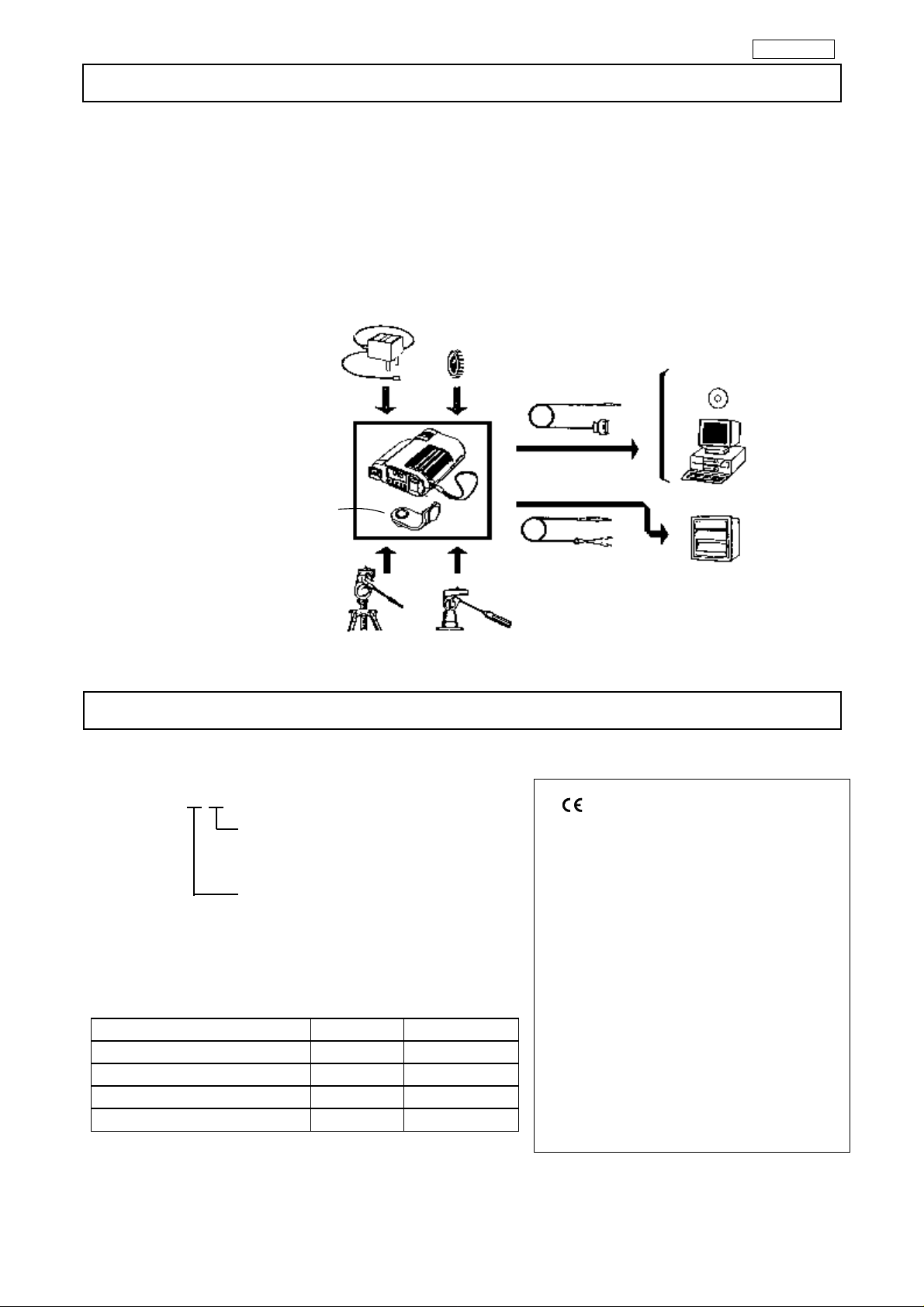
1.2 Configuration
o
C to 3000oC. The thermometers can store the temperature data measured
AC Power adaptor(IR-VHRA)
※
Close-up lens(IR-VHD)
Accessories
Tripod
mounting
adapter
RS-232C onnection cord
※
(IR -VHC)
RS- 232C
Analog output(Option)
Data logging
Software(IR -VXH2E)
Personal compute
Analog output connection cord
※
Marked are not available for CE marking(EMC directive)
Accessories
Tripod(IR-ZBMT)
2. Model and accessories
Univrsal head(IR -VMS)
※
■2.1 Model
I R-AH□□
0: Not provided
2: 0 to 1V DC
Thermometer types
T: For low temperature
Analog output (option)
■ - marking
Above models conform to EMC
directive. (89/336/EEC, 92/31/EEC
amendment, 93/68/EEC amendment)
EN61326 Emission: ClassB
Immunity: Table-Minimum immunity
S: For medium/high temperature
U: For high temperature
2.2 Accessories
Names Quantity Remarks
AA (UM-3) battery 4
Tripod mounting adapter 1
Instruction manual 1 This manual
Housing case 1
Exceptions:
AC powered model ( with AC power
Adaptor ) and analog output model
are excluded from CE-marking.
When the cord (IR-VHC3) for RS232C
is connected to the thermometer, the
thermometer becomes the exclusion
from CE-marking.
Re c eiving ins tr u ment
test requirement.
- 1 -
Page 7
INST.No.INE-374-P5CE CE Marking
M O D E
S e t M e m M I F
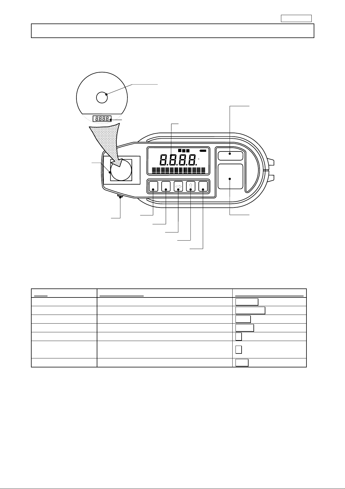
3. Names and functions of component parts
■Front
④
Collimation mark (Page7)
External display
M e a s
A H
A L
M E M
⑤
⑥
E r r o r
℃
F
E N T
⑦
①
O N / O F F
M E A S U R E
②
Viewfinder
Beam attenuation filter
selector knob(IR-AHS,
IR-AHU only) (Page 8)
Internal display
③
●Functions of keys
Keys Major functions Indications in this
Power switch
①
Measure switch
②
Memory key
③
Mode selector key
④
Shift key
⑤
Change key
⑥
Entry key
⑦
Turns on or off the power supply.
Starts or stops measurement.
Stores the measured data into memory.
Selects the screen.
Shifts the digit on programming parameters.
Changes the numeric at the selected digit on
programming parameters.
Stores the parameter programmed.
ON/OFF
MEASURE
MEM
MODE
→
↑
ENT
- 2 -
Page 8
INST.No.INE-374-P5CE CE Marking
A
A
⑨
r
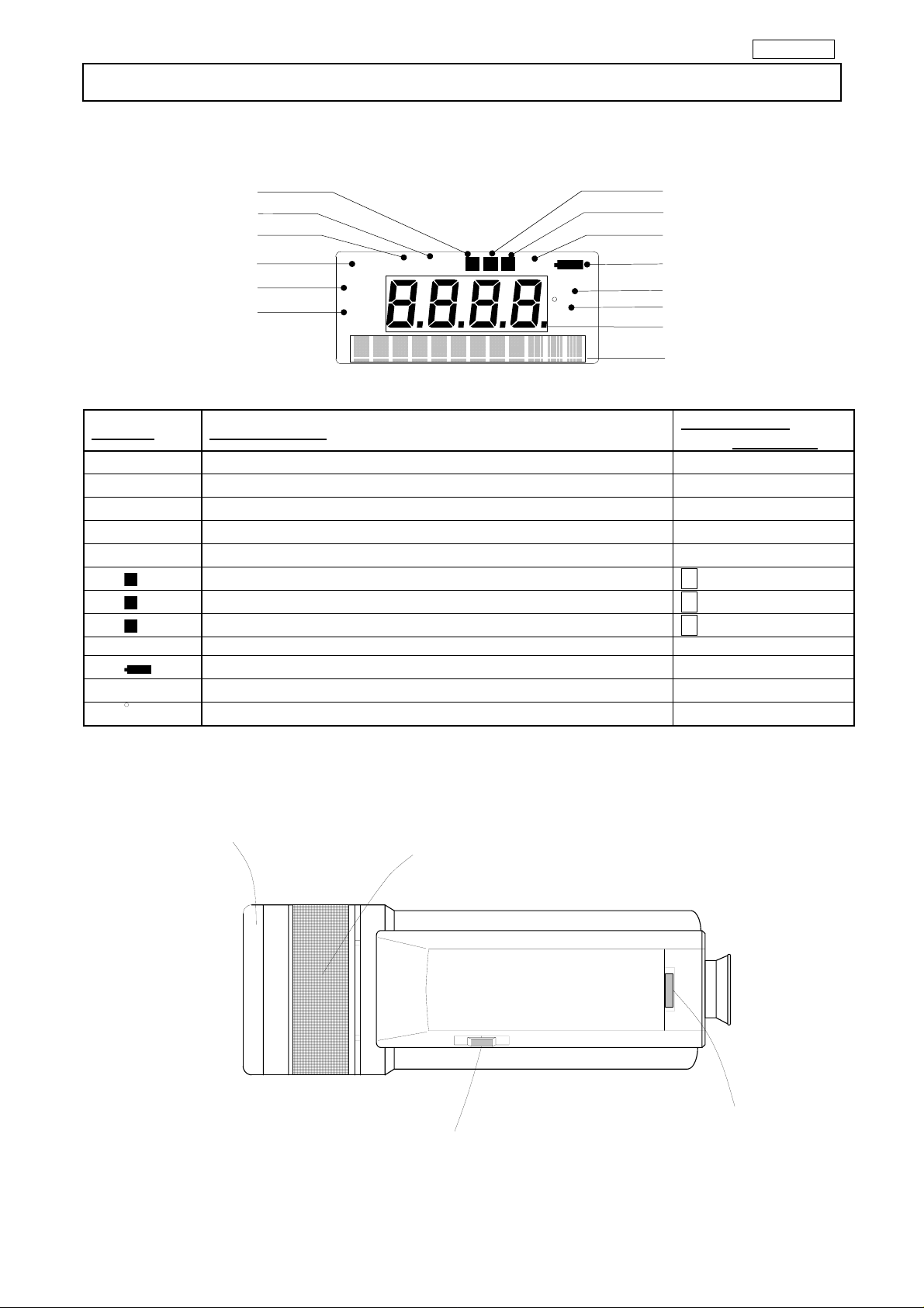
3. Names and functions of component parts
■External display
⑥
⑤
④
③
②
①
●Markers
Markers Major functions
①
②
③
④
⑤
⑥
⑦
⑧
⑩
⑪
⑫
L
H
Meas
Set
Mem
M
I
F
Erro
℃
F
Lights when the low alarm is on.
Lights when the high alarm is on.
Lights in measurement.
Lights on programming parameters or system.
Lights on programming memory or display.
Lights when the memory function is effective.
Lights when the interval memory mode is programmed.
Lights when the memory for data storage has no space.
Lights when the internal temperature of thermometer is abnormal.
Lights on low batteries.
Lights when the temperature is displayed in oC.
Lights when the temperature is displayed in oF.
■Left side panel
Cover ring
Meas
Set
AH
AL
Distance adjusting ring
Mem
MI
F
Error
℃
F
⑦
⑧
⑨
⑩
⑪
⑫
Measured value display
Parameters display
Indications in
this manual
“AL”
“AH”
“Meas”
“Set”
“Mem”
M
I
F
“Error”
“℃”
“゜F ”
Diopter adjusting dial
Beam attenuation filter selector knob
(IR-AHS and IR -AHU only)
- 3 -
Page 9
INST.No.INE-374-P5CE CE Marking
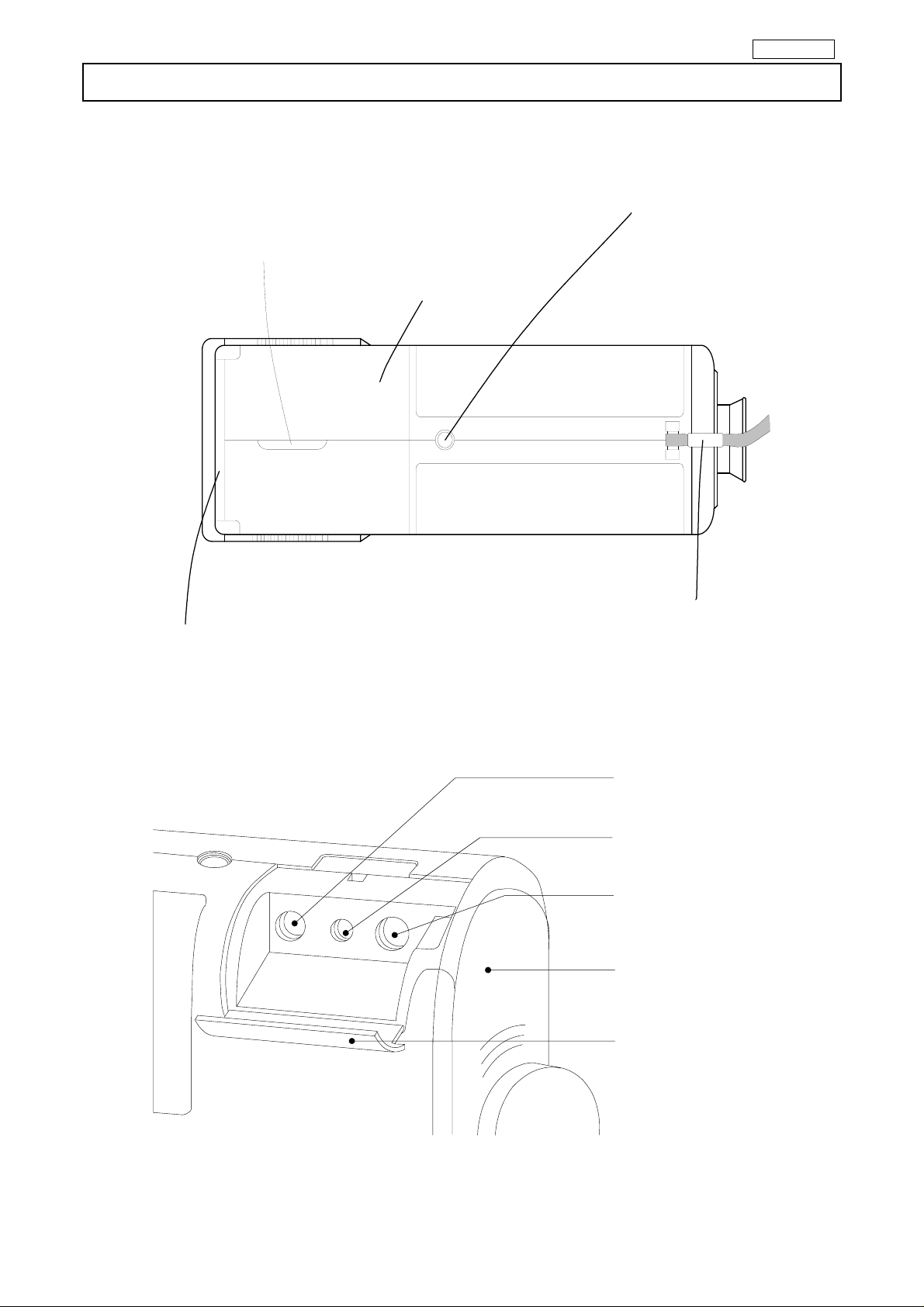
3. Names and functions of component parts
■Right side panel
Connector cover hook
Battery cover
Adapter mounting screw
Connector cover
Hand strap
■Inside connector cover
Analog output jack
(Page 17)
Jack for communications
with a PC (Page 21)
DC power supply
Jack (Page 21)
Battery cover (Page 5)
Connector cover
- 4 -
Page 10
INST.No.INE-374-P4CE CE Marking
4. Preparation for measurement
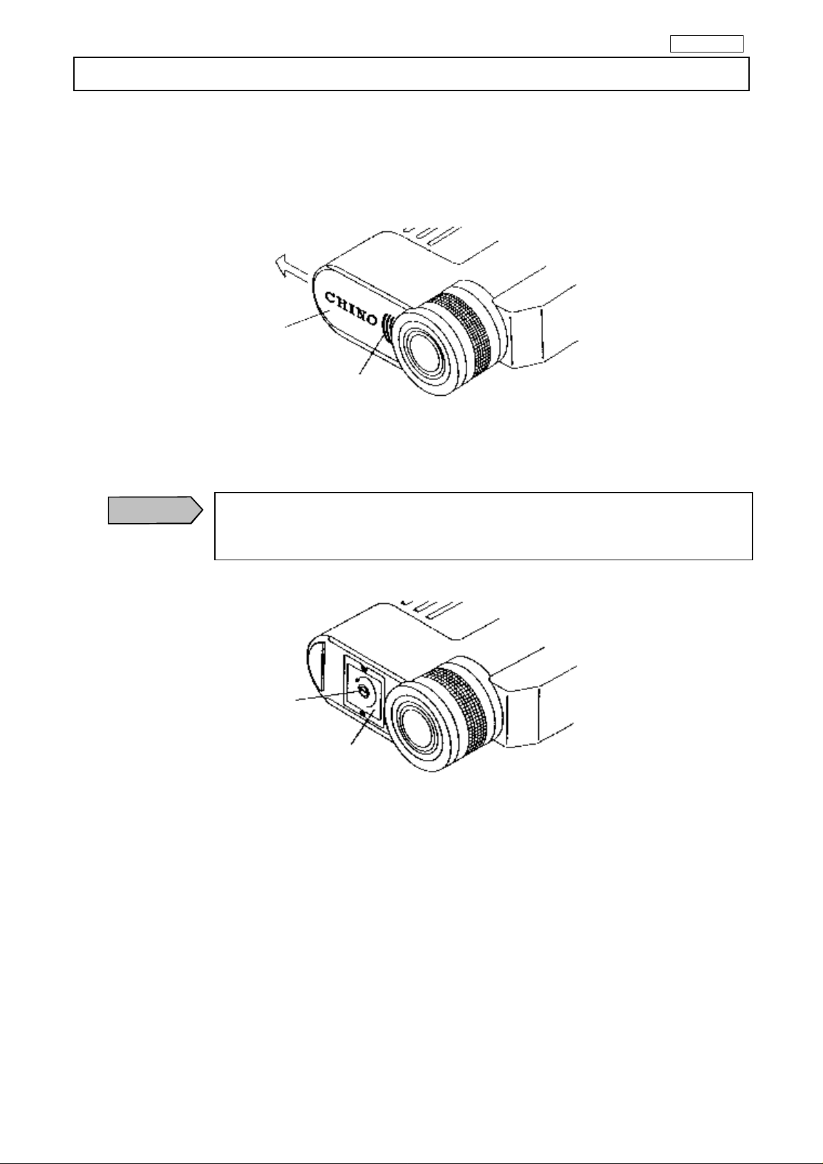
4.1 Loading batteries
◇ Removing the battery cover
Remove the battery cover by sliding it in the arrow direction while slightly pushing the
asterisked (*) part.
Batteyr cover
※
◇Removing the inside cover
Remove the inside cover by turning the cover fixing screw in the arrow direction by using
a coin.
Caution
If you mistakes polarity and insert of the battery, there is the fear that
the explosion/liquid leakage of the battery occurs and become the cause
of a fire and injury and also contaminate the surroundings.
Cover fixing
screw
Inside cover
- 5 -
Page 11

INST.No.INE-374-P4CE CE Marking
4. Preparation for measurement
◇ Loading batteries
Load the new batteries so that their polarities meet the polarity marks on the battery case.
Caution
Polarity mark
The dimensions of the inside cover is as follows.
Attach and combine the direction of 凹 department ○B of protrusion
department ○A and inside cover of the battery case.
Battery case
A
○
Battery case
◇Mounting the inside cover
Mount the inside cover so that it meets the part.
Inside cover
31
30
B
○
Unit: mm
◇ Mount the battery cover.
- 6 -
Page 12

INST.No.INE-374-P4CE CE Marking
4. Preparation for measurement
4.2 Start and stop
4.2.1 Start
Press ON/OFF key to turn the power supply on.
This thermometer checks the system just after the power supply has been turned on.
The message “System Check” appears on the parameter display during the system is checked.
S y s t h e c e m C k
After the system check is finished, the measurement screen is displayed.
On the measurement screen, the signal modulation mode is displayed at the left side and the
emissivity is displayed at the right side of the parameter display at the measurement screen.
4.2.2 Stop
Press ON/OFF key to turn the power supply off.
Caution
By pressing ON/OFF key, the shutdown processing is executed to save the
system information. Make sure to press ON/OFF key for turning off the power
supply of this thermometer.
℃
4.3 Programming temperature unit
Program the temperature unit by the procedure below.
・Press ON/OFF key while pressing MODE key to turn the power supply on.
・The temperature unit programming screen appears on the parameter display.
U n i t
℃
・Selects o C for Centigrade temperature display or o F for Fahrenheit temperature display by
↑ key.
・Press ENT key to store the temperature unit selected.
・Press ON/OFF key to turn off the power supply once.
The temperature unit stored is displayed in the next start.
Remarks
・The default temperature unit is oC.
- 7 -
Page 13

INST.No.INE-374-P4CE CE Marking
5. Measuring
5.1 Measuring procedure
・Press ON/OFF key to turn the power supply on.
・Set the measuring distance roughly by the distance adjusting ring.
・Adjust the diopter adjusting ring to see the collimation mark on the internal display clearly.
・Adjust the distance measuring ring to see the object measured clearly in the collimation mark.
・Press MEASURE key to start the measurement.
The temperature measured is displayed on the internal and external displays, and the “Meas”
marker lights on the external display.
The “OFL” is displayed if the temperature measured exceeds the measuring range or the “UFL” is
displayed if it is lower than the measuring range.
・Release MEASURE key to stop the measurement. The temperature measured just before
M e a s
℃
℃
stop is held on the internal and external displays.
5.2 Continuous measurement
For the continuous measurement, press ON/OFF key while pressing MEASURE key to turn the
power supply on. Press MEASURE key to start the measurement. The measurement is
continued until MEASURE key is pressed again.
Reference
・Batteries are consumed abruptly on the continuous measurement.
It is recommended to use the AC adapter Model IR-VHR (option) for the
continuous measurement.
5.3 Auto power off
The back-light for internal display lights out in 10 seconds after the stop of measurement.
On the continuous measurement, it lights out in 10 seconds after the start of measurement.
For lighting the back-light again, press ENT key. The back-light lights for 10 seconds.
For saving the battery life, the power supply is turned off automatically if this thermometer is not
operated for 5 minutes
- 8 -
Page 14

INST.No.INE-374-P4CE CE Marking
5. Measuring
5.4 Cautions on measurement
Warning
・Never directly face the objective lens to the sunlight for protecting your eyes
and the detecting element.
・Set the beam attenuation filter selector knob to the beam attenuation side in
advance (in case of Model IR-AHS or IR-AHU) for protecting your eyes on
the measurement of object exceeding 1500oC.
・However , when you feel glare on the measurement of objects lower
then 1500 oC, set the beam attenuation filter selection knob to the beam
attenuation side in advance.
Beam attenuation
!
Caution
・Light path
Be careful not to introduce water drops, dust particles, smoke, steam, or other
foreign substances into the light path between the object measured and the
objective lens of this thermometer.
・Interference causing high indication
Be careful not to apply the direct sunlight, light of an incandescent lamp, flame
or other thermal radiation to the object measured and the objective lens of this
thermometer.
・Abrupt change of ambient temperature
Model IR-AHT uses a thermopile as its detecting element. If the ambient
temperature changes abruptly, it takes time until the indication is stabilized.
If your thermometer is Model IR-AHT and it has been brought into a place
where a temperature difference is noticeable, leave the thermometer for about
one hour before starting the measurement.
- 9 -
Page 15

INST.No.INE-374-P4CE CE Marking
5. Measuring
5.5 Measuring
This thermometer has various measuring parameters.
The list of parameters is shown in [11. List of starting modes/screens]. By pressing MODE key
when the measurement screen is displayed, the measuring parameter programming screen is
appears with the “Set” marker lit. Measuring parameters cannot be programmed in measurement.
For programming the parameters, cancel the measurement once.
5.5.1 Programming emissivity
If the emissivity of object measured is low, the temperature displayed becomes lower than the
actual temperature and the emissivity is to be compensated.
・Press MODE key to get the emissivity programming screen.
E m i . . 0 0 1
・Press → key to shift the digit and press ↑ key to program the emissivity.
・Press ENT key to store the emissivity programmed.
The programming range is 0.10 to 1.99 (0.01 step).
Remarks
Reference
・The default emissivity is 1.00.
・ If you know the emissivity of object measured, program to its value.
If the emissivity is unknown, measure the temperature of object by a thermocouple
or other sensors and program the emissivity to display the same temperature.
The reference table of emissivity is shown in [13. Emissivity table]
5.5.2 Programming signal modulation mode
The maximum value, average value, and minimum value can be extracted continuously from the
measurement signal (real signal).
・Press MODE key to get the signal modulation mode programming screen.
M o d . e a l R
・Press ↑ key to program the mode.
Real
Peak※
Delay※
Valley※
z For the first-order lag degree in peak, delay, and valley, refer to [5.5.3 Programming modulation time
constant].
・Press [ENT] key to store the modulation mode programmed.
Remarks
The temperature measured is displayed on the real signal
without any signal modulation.
When the temperature measured increases, it is displayed
on the real signal. When the temperature measured
decreases, it is displayed on the first-order lag signal by
the time constant being programmed by the modulation
time constant programming.
The temperature measured is displayed on the first-order
lag signal.
When the temperature measured decreases, it is displayed
on the real signal. When the temperature measured
increases, it is displayed on the first-order lag signal by
the time constant being programmed by the modulation
time constant programming.
・The default mode is Real.
Measuring signal
Maxium valuc
Mean value
PEAK
DELAY
REAL
- 10 -
Page 16

INST.No.INE-374-P4CE CE Marking
5. Measuring
5.5.3 Programming modulation time constant
The modulation time constant is programmed on the signal modulation modes. The first-order lag
degree can be adjusted by the modulation time constant. The increase of modulation time constant
makes the first-order lag degree increase and the temperature measured is displayed smoothly.
・Press MODE key to get the modulation time constant programming screen.
T . C . . 9 s 9 9
・Press → key to shift the digit and press ↑ key to program the modulation time constant.
・For programming to Hold, increase the value by ↑ key at the most significant digit to
display “Hold”.
T . C . l d o ? H
・Press [ENT] key to store the time constant programmed.
The programming range of the modulation time constant is 0.0 to 99.9 seconds (0.1 second step)
and
“Hold”.
Remarks
・The default time constant is 0.0 second.
Reference
・Operation when the modulation time constant is programmed to “Hold”.
By programming the signal modulation mode to Peak, the maximum temperature
in measurement is held. By programming the signal modulation mode to Valley,
the minimum temperature in measurement is held.
By programming the signal modulation mode to Delay, the temperature measured
is displayed on condition that the modulation time constant is 99.9 seconds
5.5.4 Programming alarms
Two kinds of high alarm and low alarm can be programmed. If an alarm is on, either the “AH”
(high alarm) or the “AL” (low alarm) marker lights on the external display and the buzzer sounds.
Program to “OFF” if no alarm is required.
・Press MODE key to get either the high alarm programming screen (left figure) or the low
alarm programming screen (right figure).
A l m H f f O A l m L f f O
・Press → key to shift the digit and press ↑ key to program the alarm value
・For programming to OFF, increase the value by ↑ key at the most significant digit to
display “OFF”.
・Press ENT key to store the alarm value programmed.
Alarm programming range
Model High alarm programming range Low alarm programming range
IR-AHT
IR-AHS
IR-AHU
-50〜1000
600〜3000
900〜3000
Remarks
o
C(1oC step)、OFF -50〜1000 oC(1oC step)、OFF
o
C(1oC step)、OFF 600〜3000 oC(1oC step)、OFF
o
C(1oC step)、OFF 900〜3000 oC(1oC step)、OFF
・The default high and low alarms are “OFF”.
- 11 -
Page 17

INST.No.INE-374-P5CE CE Marking
6. Temperature data storage
This thermometer provides a function of storing temperature data measured up to maximum 1000
data into memory.
Two kinds of storage modes are prepared. The manual storage mode is to store the temperature
data being measured at the time pressing [MEM] key, and the storage-with-interval mode is to store
the temperature data being measured at every interval time programmed.
6.1 Manual storage mode
・Press [MODE] key for about 2 seconds on the measurement screen to get the storage mode
programming screen.
M M O D O f f
・Press ↑ key for programming to “Man”.
・Press ENT key to store the manual storage mode.
The M marker lights when the manual storage mode is stored.
Mem
・Press [MODE] key for returning to the measurement screen.
・Press [MEASURE] key to start the measurement.
・In measurement, press [MEM] to store the temperature data being measured at the time
into memory and the message “Data Stored” appears at the temperature data storage.
D a t a r e d S o t
M
In-not-measurement, by pressing MEM key, the temperature data being displayed at the time is
stored into memory. (When a data is stored once in-not-measurement, any data after then can not be
stored until the measurement is executed again.)
To make the memory function disable, program to “Off” in the storage mode programming screen.
MEM key does not function and the temperature data are not stored into memory.
・The default memory mode is “Off”.
Remarks
- 12 -
Page 18

INST.No.INE-374-P5CE CE Marking
6. Temperature data storage
6.2 Storage-with-interval mode
・Press [MODE] key for about 2 seconds on the measurement screen to get the storage mode
programming screen.
M M O D O f f
・Press ↑ key for programming to “Int”.
・Press ENT key to store the storage-with-interval mode.
The I marker lights when the storage-with-interval mode is stored.
Mem
・Press MODE key once to get the interval time programming screen.
I n t : 0 0 : 1 0 0
I
・Press → key to shift the digit and press ↑ key to program the interval time.
・ Press [ENT] key to store the interval time programmed. On this stage, the
storage-with-interval function does not activate.
・Press MODE key for about 2 seconds to get the measurement screen.
・Press MEM key to make the storage-with-interval function activate. The M marker lights in
addition to the I marker on the function activated.
M
I
・ Press MEASURE key to start the measurement. The temperature data at every interval
time programmed are stored into memory and the message “Data Stored” appears each
time at the temperature data storage.
D a t a r e d S o t
・To cancel the storage-with-interval function temporarily, press MEM key. The M marker
lights out.
The programming range of interval time is 1 second to 2 hours (0:00:01 to 2:00:00).
Remarks
・The default interval time is 1 minute (0:01:00).
- 13 -
Page 19

INST.No.INE-374-P5CE CE Marking
6. Temperature data storage
6.3 Display of data stored
・Press MODE key for about 2 seconds on the measurement screen to get the storage mode
programming screen.
・Press MODE key to display the temperature data stored. .
Index numbers (serial number from 1 to 1000 showing data storing numbers) are displayed on the
left side and temperature data are displayed on the right side.
The temperature data stored into memory last is displayed first.
1 0 0 0 1
℃
・Press → key to display the previous temperature data stored before the temperature data
displayed. Press ↑ key to display the next temperature data stored after the
temperature data displayed.
・Press [MODE] key for about 2 seconds to cancel the display of temperature data stored.
The message “No Data” appears if any temperature data have not been stored.
6.4 Number of temperature data stored
Maximum 1000 temperature data can be stored into memory. The temperature data exceeding
1000 cannot be stored and the F marker lights on 1000 temperature data stored.
Meas
To store the temperature data under this condition newly, delete the previous temperature data
referring to [6.5 Deletion of last storage data] and [6.6 Deletion of all storage data].
M
F
6.5 Deletion of last storage data
・The following procedure is to delete the last temperature data stored.
・Press MODE key for about 2 seconds on the measurement screen to get the storage mode
programming screen.
・Press MODE key to get the last temperature data deletion screen.
L D D E S N E O Y L
・Press → key to shift the cursor to “Yes”.
・Press ENT key.
When the data is deleted normally, the message “xxxx Erased” appears. This “xxxx” shows the
index number of the temperature data deleted.
1 0 s e d E a r
The message “No Data” appears if any temperature data have not been stored.
・Press MODE key for about 2 seconds to cancel the last temperature data deletion.
- 14 -
Page 20

INST.No.INE-374-P5CE CE Marking
6. Temperature data storage
6.6 Deletion of all storage data
・The following procedure is to delete all temperature data stored,
・Press MODE key for about 2 seconds on the measurement screen to get the storage mode
programming screen.
・Press MODE key to get all temperature data deletion screen.
A D D E S N E O Y L
・Press → key to shift the cursor to “Yes”.
・Press ENT key.
When the data are deleted normally, the message “All Erased” appears.
1 0 s e d E a r
The message “No Data” appears if any temperature data have not been stored.
・Press MODE key for about 2 seconds to cancel all temperature data deletion.
- 15 -
Page 21

INST.No.INE-374-P5CE CE Marking
7. User calibration
For the routine calibration of this thermometer, the user calibration function is provided to
recalibrate this thermometer by using your black body furnace for calibration.
The calibration is executed on two optional temperature points.
7.1 Calibration method
・Press ON/OFF key while pressing MODE key to turn the power supply on.
・Press MODE key several times to get the zero/span calibration execution screen.
C M P N O O G
・Press → key to shift the cursor to “GO”.
Reference
・Press ENT key to get the zero side calibration data programming screen.
The temperature data being displayed is on the real signal not being converted through emissivity
compensation, signal modulation, and modulation time constant.
Meas
Set
・Measure the temperature of your black body furnace.
・During the measurement of the black body furnace temperature, press → key to shift the
digit and press ↑ key to change the temperature displayed to the calibrated temperature
of black body furnace
Caution
・Press ENT key to store the calibration data at the zero side.
As the confirmation of calibration data storage, the asterisk (*) appears beside the character “Zero”.
Z e r o 0 0
Caution
・Press MODE key once to get the span side calibration data calibration screen.
S p a n 0 0
Press MODE key on this condition, when you want to calibrate the span side
only without calibration the zero side.
℃
Use the ↑ key in the case that the numerical value is set up. However, do it
after the column that sets up the numerical value is selected with the → key.
If push the ↑ key without selecting the column, transferring it to the upper most
column and the numerical value has done UP.
7 *
The auto power off function works when time is required to the span side
calibration work start after zero side calibration ended, and the power supply
becomes the condition of off.
(In the case that there is not key operation for 5 minutes)
0 3
℃
℃
- 16 -
Page 22

INST.No.INE-374-P5CE CE Marking
7. User calibration
・Measure the temperature of your black body furnace, and program and store the calibrated
temperature of black body furnace in the same way as the programming of calibration data
at zero side. Make sure that the calibration data at span side is greater than the calibration
data at zero side
Reference
・Press [MODE] key once more to get the calibration operation execution screen.
C A L . N O O G
・Press → key to shift the cursor to “GO”..
・Press ENT key to start the calibration operation.
・When the calibration operation finishes correctly, the message “Completed” appears
forseveral seconds
C o m p d e e t l
・For making the calibrated data effective, restart this thermometer.
Remark
Set up it so in this case, it becomes span calibration data>zero calibration data.
・If zero/span calibration data are not stored or if the calibration data at zero side
> the calibration data at span side, the message “Data Abnormal” appears
and the calibration operation is not executed.
7.2 Recovery of calibration data
This function is to recover, after the execution of the user calibration, the calibration data to the
previous data.
This thermometer stores the previous calibration data at the execution of the user calibration.
The following procedure is to recover the calibration data to the previous data stored.
・Press ON/OFF key while pressing [MODE] key to turn the power supply on.
・Press MODE key twice to get the zero/span calibration execution screen.
C M P N O O G
・Press → key to shift the cursor to “GO”.
・Press ENT key to get the zero calibration data programming screen.
・Press MODE key three times to get the calibration data recovery screen.
U n d o N O O G
・Press [→] key to shift the cursor to “GO”.
・Press [ENT] key.
After the calibration data recovery finishes correctly, the message “Completed” appears.
C o m p d e e l l
・For making the recovered calibration data effective, restart this thermometer.
Caution
When the recovering to the previous calibration data from the current calibration
data is executed, the current calibration data is erased and the recovering operation
can not be executed again until the next user calibration is executed. For initializing
to the default calibration data, refer to [9.5 Initializing to the default condition.].
- 17 -
Page 23

INST.No.INE-374-P5CE CE Marking
8. Analog Output
If your thermometer is with the optional analog output function, the analog output of 0 to 1V
corresponding to the temperature data measured. (Models IR-AHT2, IR-AHS2 and IR-AHU2)
You can record the temperature data measured on a recorder by this function
8.1 Programming scale
An optional temperature scaling to an analog output of 0 to 1V can be programmed.
・Press ON/OFF key while pressing MODE key to turn the power supply on.
・Press MODE key once to get the high output scaling value programming screen.
O H 0 0
・Press → key to shift the digit and press ↑ key to program the high output scaling value.
・Press ENT key to store the high output scaling value programmed.
・Press MODE key once more to get the low output scaling value programming screen.
O
0 0
L
0 2
0
1
℃
℃
・Press → key to shift the digit and press ↑ key to program the low output scaling value.
・Press ENT key to store the low output scaling value programmed.
・Press ON/OFF key to turn the power supply off.
On the next start-up of this thermometer, you can get the analog output of 0 to 1V within the scaling
range programmed.
The analog output programming range is mentioned below.
Model
High output scaling value programming
range
IR-AHT -50 to 1000 oC(1oC step) -50 to 1000 oC(1oC step)
IR-AHS 600 to 3000 oC(1oC step) 600 to 3000 oC(1oC step)
IR-AHU 900 to 3000 oC(1oC step) 900 to 3000 oC(1oC step)
Remarks
・The default scaling values
o
IR-AHT 1000
IR-AHS 3000
C (Maximum scaling), -50 oC (Minimum scaling)
o
C (Maximum scaling), 600 oC (Minimum scaling)
IR-AHU 3000 oC (Maximum scaling), 900 oC (Minimum scaling)
Low output scaling value programming
range
8.2 Connections
Connect the analog output cable attached to the analog output jack inside the connector cover.
Connect it to the innermost of the jack securely.
For the place of the analog output jack, refer to [3. Names and functions of component parts].
8.3 Temperature data on analog output
The temperature data on analog output are the same as those being displayed and the data are
converted through emissivity compensation, signal modulation, and modulation time constant.
- 18 -
Page 24

INST.No.INE-374-P5CE CE Marking
s
9. Maintenance and check
9.1 Self-diagnostic function
9.1.1 Low battery
The battery warning marker lights on the external display when the battery capacity becomes lower
than a certain level and replace them at once with the new batteries.
Caution
Meas
For replacing the batteries, refer to [4.1 Loading batteries].
Battery warning marker.
9.1.2 Abnormal internal temperature
If the temperature inside this thermometer becomes abnormal, the inside temperature error marker
lights on the external display.
Caution
The inside temperature error marker lights when the inside temperature of
M
I
Error
Inside temperature
thermometer becomes lower than 0oC or higher than 55oC.
Measurement cannot be executed correctly under such an environment.
Check the ambient temperature.
9.1.3 EEPROM error
If EEPROM storing the parameters and the temperature data becomes in error, the message
“EEPROM ERROR” appears at the access timing to EEPROM.
E E P R r r o M E r O
Caution
The parameters and the temperature data can be stored into memory under thi
condition. Contact your nearest CHINO’s sales agent.
9.1.4 Status display
If → key is pressed for about 2 seconds on the measurement screen in the stop condition, the status
of this thermometer are displayed on the external display. Press MODE key to switch the screens.
The following status are displayed.
・Inside temperature
・Model
・Serial number
・Measuring temperature range
・Measuring wavelength
Press → key for about 2 seconds for returning to the measurement screen.
- 19 -
Page 25

INST.No.INE-374-P5CE CE Marking
9. Maintenance and check
9.2 Storage
Caution
・Don’t store this thermometer at a hot and/or wet place.
・Make sure to mount the lens cap for storage.
・Remove the batteries if this thermometer is not used for longer than 2
weeks, otherwise this thermometer may become defective due to an electrolyte
leak failure of the batteries.
9.3 Cleaning of cover glass
Wipe the cover glass inserted into the cover ring periodically with a soft cloth.
In case of Model IR-AHT, the cover glass is mounted at a deep position. Remove the ring from
the thermometer to wipe the cover glass.
9.4 Cleaning of external display and eyepiece cover
Clean them periodically with a soft cloth.
9.5 Initializing to default condition
For initializing this thermometer to the default condition, press ON/OFF key while pressing ENT
and ↑ keys. The message “Initialized” appears to confirm the initialization.
I n i t z e d a i l i
Caution
Remarks
・By this operation, all parameters are initialized to the default condition and
the temperature data stored are erased.
・For the default parameters, refer to [11.2 Table of screens]
- 20 -
Page 26

INST.No.INE-374-P5CE CE Marking
10. Accessories
10.1 Close-up lens (Model: IR-VHD: For IR-AHS and IR-AHU)
This lens is used for the measuring distance less than 0.5m.
The measuring diameter is determined by the distance factor. The measuring diameter is
expressed by the following formula.
(Measuring diameter) / (Measuring factor) – Measur ing diameter ø D (Unit: mm)
(Example) As the distance factor of Model IR-AHS is 100, the relation of measuring
distance and measuring diameter is shown as:
250 to 520/100 = ø2.5 to ø5.4 (Unit: mm)
The measuring distances and the measuring diameters of each model are shown in the table.
In case of Model IR-AHS, it is possible to measure the object with the diameter of ø1 at the
measuring distance of 100 mm.
Model Distance Min. diameter (IR-AHS) Min. diameter (IR-AHU)
IR-VHD13 100 to 130(mm)
IR-VHD18 130 to 180(mm)
IR-VHD29 180 to 290(mm)
IR-VHD54 250 to 540(mm)
φ1 toφ1.3(mm)
φ1.3 toφ1.8(mm)
φ1.8 toφ2.9(mm) φ0.7 toφ1.2(mm)
φ2.5 toφ5.4(mm) φ1.0 toφ2.2(mm)
■Mounting Method
・Remove the cover glass ring from the lens cylinder tip by turning it.
・Mount the close-up lens to the lens cylinder tip by screwing it.
Cover glass ring
Lens cylinder
Remarks
Cover lens
・No cover glass can not be used for the close-up lens.
- 21 -
Page 27

INST.No.INE-374-P5CE CE Marking
10. Accessories
10.2 AC adapter (Model IR-VHRA)
!
The adapter is for operation of this thermometer with AC power supply and is effective for use in
the continuous measurement mode.
For the connection, insert the plug of the adapter into the DC power jack. For the place of the DC
power jack, refer to [Inside connector cover] in [3. Names and functions of component parts].
Warning
・Make sure that 100VAC is used for the AC adapter.
If not, electrical shock, fire, damage may occur.
Caution
・Do not touch the AC adapter or receptacle with wet hands.
・Do not wet the AC adapter. Fire may cause.
・Wipe out the dust on the AC adapter . Fire may cause.
・Connect the AC adapter to this thermometer with the power supply turned off.
10.3 Tripod (Model IR-ZBMT) and Universal head (Model IR-VMS)
These accessories are used for fixing this thermometer for long-term measurement.
Mount the tripod or the universal head via the tripod mounting adapter attached, if required.
Tripod mounting screw(W 1/4)
for d irect fixin g
Tripod mounting adapter
10.4 Data Logging Software (IR-AH Data Logging Software)
Three kinds of data management mode, real-time trend mode, multi-point monitoring mode by
utilizing memory, and 1-point historical trend mode, are available.
Graph display, report creation, printing, and data storage can be easily executed.
The export of the measured data to spreadsheet applications is also possible.
- 22 -
Page 28

INST.No.INE-374-P5CE CE Marking
11. List of Starting Modes/Screens
11.1 Modes at start time
The following operation modes are available by the key combinations at the start time.
Keys Modes Remarks
Press ON/OFF key only
Press ON/OFF while pressing MEASURE key
Press ON/OFF key while pressing MODE key
Press ON/OFF key while pressing ENT and
Standard measurement
Continuous measurement
System programming No measurement can be
Initialization After initialization, the
↑ keys together
11.2 Table of screens
The screens displayed on the external display are the following 4 kinds basically.
Modes
Programming
How-to-display from
measurement screen
Press MODE key.
measuring parameters
Programming and
display on
Press MODE key for 2
seconds.
temperature data
storage
Status display
Press → key for 2
seconds.
Press ON/OFF key while
System programming
pressing MODE key to
turn the power supply on.
For changing screens, press MODE key.
Makers
appeared
"Set"
"Mem"
"Set"
executed.
standard measurement is
executed.
Return to measurement screen
Press MODE key on the low alarm
programming screen.
Press MODE key for 2 seconds.
(Enable from any screen)
Press → key for 2 seconds.
(Enable from any screen)
11.2.1. Measuring parameters programming/display items
Screen Display Programming range Default
Emissivity Emi. 0/10 to 1.99 1.00
Signal modulation mode Mod. Real, Peak, Valley, Delay Real
Signal modulation time constant T.C. 0.0 to99.9 seconds, HOLD 0.0 second
High alarm AlmH -50 to 1000 oC, OFF (IR-AHT)
600 to 3000
900 to 3000
Low alarm AlmL -50 to 1000 oC, OFF (IR-AHT)
600 to 3000
900 to 3000
o
C, OFF (IR-AHS)
o
C., OFF (IR-AHU)
o
C, OFF (IR-AHS)
o
C., OFF (IR-AHU)
OFF
OFF
11.2.2. Temperature data storage programming/display items
Screen Display Programming range Default
Storage mode MMOD OFF, Man, Int OFF
Interval time programming Int 00:00:01 to 02:00:00 00:01:00
Storage data display
Last storage data deletion LDDEL
All storage data deletion ADDEL
The interval time programming screen is only displayed when the storage mode is programmed to
“Int”.
- 23 -
Page 29

INST.No.INE-374-P5CE CE Marking
n
s
11. List of Starting Modes/Screens
11.2.3 Status display items
Screen Display
Inside temperature Dtemp
Model Model
Serial number SN
Measuring temperature range R
Measuring wavelength WL
11.2.4. System programming display items
Screen Display Programming range Default
Temperature unit Unit
Output scaling high limit *1 OH -50 to 1000 oC (IR-AHT)
Output scaling low limit *1 OL -50 to 1000 oC (IR-AHT)
o
C, oF
600 to 3000
900 to 3000
600 to 3000
900 to 3000
o
C (IR-AHS)
o
C (IR-AHU)
o
C (IR-AHS)
o
C (IR-AHU)
Zero/span calibration execution CMP
Calibration data programming at
zero side *2
Calibration data programming at
span side *2
Calibration operation execution
Zero -50 to 1000 oC (IR-AHT)
600 to 3000
900 to 3000
Span -50 to 1000 oC (IR-AHT)
600 to 3000
900 to 3000
o
C (IR-AHS)
o
C (IR-AHU)
o
C (IR-AHS)
o
C (IR-AHU)
CAL
*2
Calibration data recovery *2 Undo
o
C
o
C (IR-AHT)
1000
o
3000
C (IR-AHS)
o
3000
C (IR-AHU)
o
C (IR-AHT)
-50
o
600
C (IR-AHS)
o
900
C (IR-AHU)
o
C (IR-AHT)
-50
o
600
C (IR-AHS)
o
900
C (IR-AHU)
o
C (IR-AHT)
1000
o
3000
C (IR-AHS)
o
3000
C (IR-AHU)
*1: The output scaling high limit and output scaling low limit are only displayed on the
thermometers with analog output (option).
*2: The screens for the zero side calibration data programming, the span side calibration data
programming, the calibration operation execution and the calibration data recovery are only
displayed when you select “GO” on the zero/span calibration execution screen.
12. General Specificatio
12.1 External dimensions
135
60
- 24 -
175
Un it:mm
Page 30

INST.No.INE-374-P5CE CE Marking
n
s
12. General Specificatio
12.2 Specifications
Model IR-AHS IR-AHU IR-AHT
Measuring System Narrow band radiation thermometer
Detecting Element Si Thermopile
Measuring
Wavelength
Measuring Range 600 to 3000°C 900 to 3000°C -50 to 1000°C
Accuracy Ratings
Repeatability 1°C ± 1digit
0.96µm 0.65µm 8 to 13µm
Lower than 1500°C: ±0.5% of measured value ± 1digit
1500°C to 2000°C: ±1% of measured value ± 1digi0t
Higher than 2000°C: ±2% of measured value ± 1digit
(ε= 1.0, Reference operating condition: 23°C ± 5°C, 35 to 75%RH)
1) Temperature drift:0.015% of measured value / °C
Stability
Resolution 1°C 1°C (More than 50°C)
Response Time 0.5 second 1 second
Emissivity
Compensation
Signal Modulation
Display System LCD digit al 4 digi ts , Di spl ayed in the finder and on the panel board
Data
StorageFunction
Users’ Calibration
Function
Output Signal Digital transmission(RS-232C),Analog output(0 to 1V DC, option)with a cord
Communications
Function
Optical System Focusable lens type
Distance Factor
2) Stability: ±5°C under EMC test environment
=1.00 to 0.10 (0.01 increment)
ε
modulation : Real, Peak, Delay, and Valley .
modulation ratio:0 to 99 seconds, 1-sec increment
Peak hold, Valley hold, Hold with the measuring switch turned off.
Maximum 1000 data
Calibration at zero and span
RS-232C (The data logging software is sold separately.)
100(Measuring distance
L / Measuring diameter D)
250 (Measuring distance
L / Measuring diameter D)
Wide band radiation
thermometer
Lower than 200°C: ±2°C ±
1digit
High than 200°C: ±1% of
measured value ± 1digit
1) T emperature drift:
Lower than 300°C: 0.15°C/°C
300-700°C:0.05
Higher than 700°C: 0.025
2)Stability: ±15°C underEMC
Cassegrain focusable mirror
type
40 (Measuring distance
L / Measuring diameter D)
% of
measured value /°C
% of
measured value /°C
test environment
Measuring Distance L = 500mm to ∞ L = 700mm to ∞
Measuring
Diameter
Collimation Direct viewing finder
Lens Diameter Ø30mm Ø40mm
Other Functions
Ambient
Temperature
Power Supply AA (UM-3) battery, 4 pieces (about 20 hours for continuous measurement)
Casing Material
and Color
Outside Dimensions
and Weight
Attachment 4 pieces of AA (UM-3 battery), Adapter for tripod, Housing case
D = L / 100(ø, mm) D = L / 250(ø, mm) D = L / 40(ø, mm)
Auto-power-off, Continuous measurement, °C / °F selection, Battery check,
High / low alarms
0 to 50°C
ABS resin, Gray
W135 x H60 x D175mm, About 700g (thermometer only)
- 25 -
Page 31

INST.No.INE-374-P5CE CE Marking
13. Emissivity table
The emissivity are values determined by the material of object, profile of its surface, surface
roughness, oxidized or not, measuring temperature, measuring wavelength and other factors.
They are represented by the thermal radiation ratio "ε" when a black body furnace at the same
temperature is measured in the same wavelength band.
The emissivity "ε" is generally known by a value at the wavelength of 0.65µm when an optical
pyrometer is used. The emissivity changes according to the above factors even in case of the same
material. Please use the following table as a reference.
13.1 Emissivity table (λ= 0.65µm)
Metal
Zinc 0.42
Alumel 0.37
Aluminum 0.17 0.12
Antimony 0.32
Iridium 0.30
Yttrium 0.35 0.35
Uranium 0.54 0.34
Gold 0.14 0.22
Silver 0.07 0.07
Chromium 0.34 0.39
Chromel P 0.35
Cobalt 0.36 0.37 Yttrium oxide 0.60
Constantan 0.35 ― Uranium oxide 0.30
Zirconium 0.32 0.30 Cobalt oxide 0.75
Mercury
Tin 0.18
Carbon 0.8 to 0.9
Tungsten 0.43
Tantalum 0.49
Cast iron 0.37 0.40 Iron oxide 0.63 to 0.98
Titanium 0.63 0.65 Copper oxide 0.60 to 0.80
Iron 0.35 0.37 Thorium oxide 0.20 to 0.57
Copper 0.10 0.15 Vanadium oxide 0.70
Thorium 0.54 0.34 Beryllium oxide 0.07 to 0.37
Nickel 0.36 0.37 Magnesium oxide 0.10 to 0.43
80Ni /20Cr 0.35
60Ni / 024Fe / 16Cr 0.36
Platinum 0.30 0.38
90Pt / 10Rh 0.27
Palladium 0.33 0.38
Vanadium 0.35 0.35
Bismuth 0.29
Beryllium 0.61 0.61
Manganese 0.59 0.59
Molybdenum 0.37 0.40
Rhodium 0.24 0.30
Emissivity
Solid Liquid
― Alumel(*)
― Chromel(*)
―
― Cast iron(*)
―
―
0.23 Columbium oxide 0.55 to 0.71
―
―
―
―
―
―
―
―
Oxide Emissivity
0.87
0.87
Constantan(*)
Ceramics 0.25 to 0.5
55Fe. 37.5Cr. 7.5Al(*)
70Fe. 23Cr. 5Al. 2Co(*)
80Ni. 20Cr(*)
60Ni. 24Fe. 16Cr(*)
Stainless steel(*)
Aluminum oxide 0.22 to 0.4
Zirconium oxide 0.18 to 0.43
Tin oxide 0.32 to 0.60
Cerium oxide 0.58 to 0.82
Titanium oxide 0.50
(*) : Oxidized on surfaces
0.84
0.70
0.78
0.75
0.90
0.83
0.85
- 26 -
Page 32

INST.No.INE-374-P5CE CE Marking
13. Emissivity table
13.2 Emissivity table (λ= 0.9µm)
Metal Emissivity
Aluminum 0.10 to 0.23
Gold 0.015 to 0.02
Chrome 0.36
Cobalt 0.28 to 0.30
Iron 0.33 to 0.36
Copper 0.03 to 0.06
Tungsten 0.38 to 0.42
Titanium 0.50 to 0.62
Nickel 0.26 to 0.35
Platinum 0.25 to 0.30
Molybdenum 0.28to 0.36
Alloy Emissivity
Inconel X 0.40 to 0.60
Inconel 600 0.28
Inconel 617 0.29
Inconel 0.85 to 0.93
Incoloy 800 0.29
Kanthal 0.80 to 0.90
Stainless steel 0.30
Hastelloy X 0.3
Semi conductor Emissivity
Silicon 0.69 to 0.71
Germanium 0.60
Gallium arsenic 0.68
Ceramics Emissivity
Silicon carbide 0.80 to 0.83
Titanium carbide 0.47 to 0.50
Silicon nitride 0.89 to 0.90
Other Emissivity
Carbon pigment 0.90 to 0.95
Graphite 0.87 to 0.92
13.3 Emissivity table (λ= 1.55µm)
Metal Emissivity
Aluminum 0.09 to 0.40
Chrome 0.34 to 0.80
Cobalt 0.28 to 0.65
Copper 0.05 to 0.80
Gold 0.02
Steel plate 0.30 to 0.85
Lead 0.28 to 0.65
Magnesium 0.24 to 0.75
Molybdenum 0.25 to 0.80
Nickel 0.25 to 0.85
Palladium 0.23
Platinum 0.22
Rhodium 0.18
Silver 0.04 to 0.10
Tantalum 0.20 to 0.80
Tin 0.28 to 0.60
Titanium 0.50 to 0.80
Tungsten 0.30
Zinc 0.32 to 0.55
Alloy Emissivity
Brass 0.18 to 0.70
Chromel, Alumel 0.30 to 0.80
Constantan, Manganin 0.22 to 0.60
Inconel 0.30 to 0.85
Monel 0.22 to 0.70
Nickel Chrome 0.28 to 0.85
Ceramics Emissivity
Alumina ceramics 0.30
Red brick 0.80
White brick 0.35
Silicon brick 0.60
Sillimanite brick 0.60
Ceramics 0.50
Other Emissivity
Asbestos 0.90
Asphalt 0.85
Carbon 0.85
Graphite 0.80
Soot 0.95
Cement, Concrete 0.70
Cloth 0.80
- 27 -
Page 33

32-8, KUMANO-CHO, ITABASHI-KU, TOKYO 173-8632
Telephone: +81-3-3956-2171
Facsimile: +81-3-3956-0915
Web site http://www.chino.co.jp/
INE-374-P5CE Aug-'03 IR-AH□□Series PORTABLE DIGITAL RADIATION THERMOMETER Printed in Japan ( Kuki )
 Loading...