

Page 1
INST.No. INE-866
R
EH3000 series
(DOT-PRINTING TYPE/PEN TYPE)
180 mm ANALOG RECORDE
Instruction Manual
Page 2

Page 3

-CONTENTS-
❐INTRODUCTION / REQUESTS /
WARRANTY / NOTICES ······································· 1
FOR SAFE USE ··············································· 2
WARNING ························································ 3
❐MAIN FEATURES AND FUNCTIONS ·········· 4
1. BEFORE USE ··················································· 5
1.1 Model Check and Information ························· 5
1.2 Attachments and Consumable Parts ············· 8
1.3 Flow Chart to Startup ······································ 10
2. INSTALLATION ··············································· 11
2.1. Mounting Place ·············································· 11
2.2 External Dimensions ······································ 12
2.3 Mounting Method on Panel ····················· 13
2.4 Release of Shipping Status ····················· 14
3. FRONT ····························································· 16
3.1 Names of Front Portions ·························· 16
3.2 Display Operation Part ····························· 17
4. CONNECTIONS ············································· 19
4.1 Terminal Board ·········································· 19
4.2 Cautions on Connection ·························· 20
4.3 Power Supply & Protective Conductor
Terminals
4.4 Measuring Input Terminals ······················ 22
4.5 Alarm Output Terminals (Optional) ········· 26
5. LOADING ························································· 28
5.1 Inkpad Loading (For dot-printing type) ··· 28
5.2 Cartridge Pen Loading (For pen type) ······ 31
5.3 Chart Loading ············································ 34
6. OPERATION/SETTING ································· 37
6.1 Turning Power On/Off ···································· 37
6.2 Operation/Setting Change ····························· 40
6.3 Chart Feed Operation ······························ 44
··················································· 21
6.4 Recording Operation (AUTO CH/
INDICATE Switch) ·········································· 45
6.5 Pen Marker (Only for 2/3 pen type) ········· 47
6.6 Chart Speed Change ····································· 48
6.7 Alarm Specifications ······································· 50
6.8 Alarm Setting ··················································· 51
6.9 Operation/Setting Function Depending on
Application
················································· 58
7. OPERATION ···················································· 60
7.1 Recording Operation (Pen type) ··················· 60
7.2 Alarm Activation/Reset and Behavior ··········· 61
7.3 Behavior on Abnormal Input ·························· 63
8. OPTION ···························································· 64
8.1 Shunt Resistor for Current Input ·············· 64
8.2 Dotting Interval 3 Seconds (Dot-printing
type option) ······················································ 65
9. ADJUSTMENT ················································ 66
9.1 User Indication Adjustment/Indication
Check
························································· 66
9.2 Shift Programming ·········································· 75
10. MAINTENANCE ············································ 80
10.1 Routine Inspection ·································· 80
10.2 Troubleshooting ······································ 83
1
0.3 Recommended Parts Replacement
Intervals
······················································ 85
11. SPECIFICATIONS ········································ 86
11.1 Detailed Specifications ································· 86
11.2 Option Specifications ···································· 88
11.3 Accuracy Rating List ····································· 89
12. DISPOSAL ····················································· 91
The items marked with
in titles contain
Warning
Caution
Read these items without fail.
.
and
Page 4

❐INTRODUCTION / REQUESTS / WARRANTY / NOTICES
Thank you for your purchase of EH3000 Series Analog Recorder (Dot-printing
type/Pen type) with 180 mm recording width.
Make sure to read this instruction manual in advance to understand this
product well and prevent troubles from occurring.
Important Notice
1. To the persons doing instrumentation, installation, and sales
Make sure to provide this instruction manual to the person who uses this product.
2. To the users of this product
Store this instruction manual with care until you scrap this product.
Also, write down the parameter contents set in the product and keep it for your record.
This product is warranted for one year from the date of delivery. If it is damaged during the warranty period,
when used normally based on the cautions in the instruction manual and labels attached to the product, etc., it
will be repaired without any charge (only in Japan). In the case, we are sorry to trouble you, but please contact
your dealer or nearest our sales office.
However, in cases of the followings, it will be repaired at your expense even during warranty period.
1. Failure or damage caused by improper use or connection, or invalid repair or modification.
2. Failure or damage caused by fire, earthquake, wind or flood, thunderbolt, or other extraordinary natural
phenomena, or pollution, salt, harmful gas, abnormal voltage, or use of unspecified power.
3. Replacement of parts or accessories that have reached the end of their life.
Furthermore, the term ‘warranty’ in this sense covers only a CHINO’s product itself. Therefore, we are not
responsible for compensation for whatever the damage that is triggered by failure of our product.
1. No part of this manual can be reproduced or copied in any form without permission.
2. The contents of this manual may be altered without prior notice.
3. This manual has been documented by making assurance doubly sure. However, if any question arises or if any
error, an omission, or other deficiencies are found, please contact your nearest our sales office.
4. CHINO is not responsible for any operation results of this software.
Product warranty scope
Notices
-1-
Page 5
FOR SAFE USE
For correct use of this product, please be sure to read and understand the following cautions.
(1) Preconditions for Use
This product is a general electronic device (measuring instrument) to be used mounted on an indoor instrumentation panel (except for
portable type). Avoid using under other conditions.
Use after the system safety is implemented such as the fail-safe design and periodical inspection on the final product side. Also, for
wiring/adjustment/operation of the product, ask professionals with instrumentation knowledge to perform.
Furthermore, also the person who actually uses the product is required to read this instruction manual to fully understand various
cautions and basic operation.
(2) Labels Employed
For safe use of the unit, the following labels are used.
Label
Name Meaning
(3) Symbols in This Instruction Manual
The cautions to be observed for preventing damages and unexpected accidents are identified by the following symbols according to
their importance degrees to use this product safely.
Symbol Range of cautions
Alert symbol mark Place to be handled with cautions to avoid “electric shock”, “injuries”, etc.
Protective conductor terminal
Caution for high temperature Place to be handled with cautions to avoid “burns”.
This symbol is indicated at the titles (items) where
explained. Make sure to read these explanations.
Cautions are explained to avoid causes for death or serious injuries of users.
Cautions are explained to avoid causes for slight injuries of users or damages of this product or peripheral
devices.
To avoid “electric shock” make sure to connect (ground) protective
conductor of a power supply.
or is
This symbol indicates cautions when this product does not function as specified or when such a possibility
exists.
This reference serves as a supplement for handling (operation) and it is convenient for using.
(4) Request
1. Do not drop the product while taking it out of the box
2. When transporting the unit, pack in the dedicated package box, and put the box in an outer case with a bed of cushion. With the
consideration to the case above, it is recommended that the dedicated package box for the unit is stored.
3. When the unit is removed from the panel and not used for a long time, put it in the dedicated package box, and store it in a place with
normal ambient temperature and less dust.
-2-
Page 6
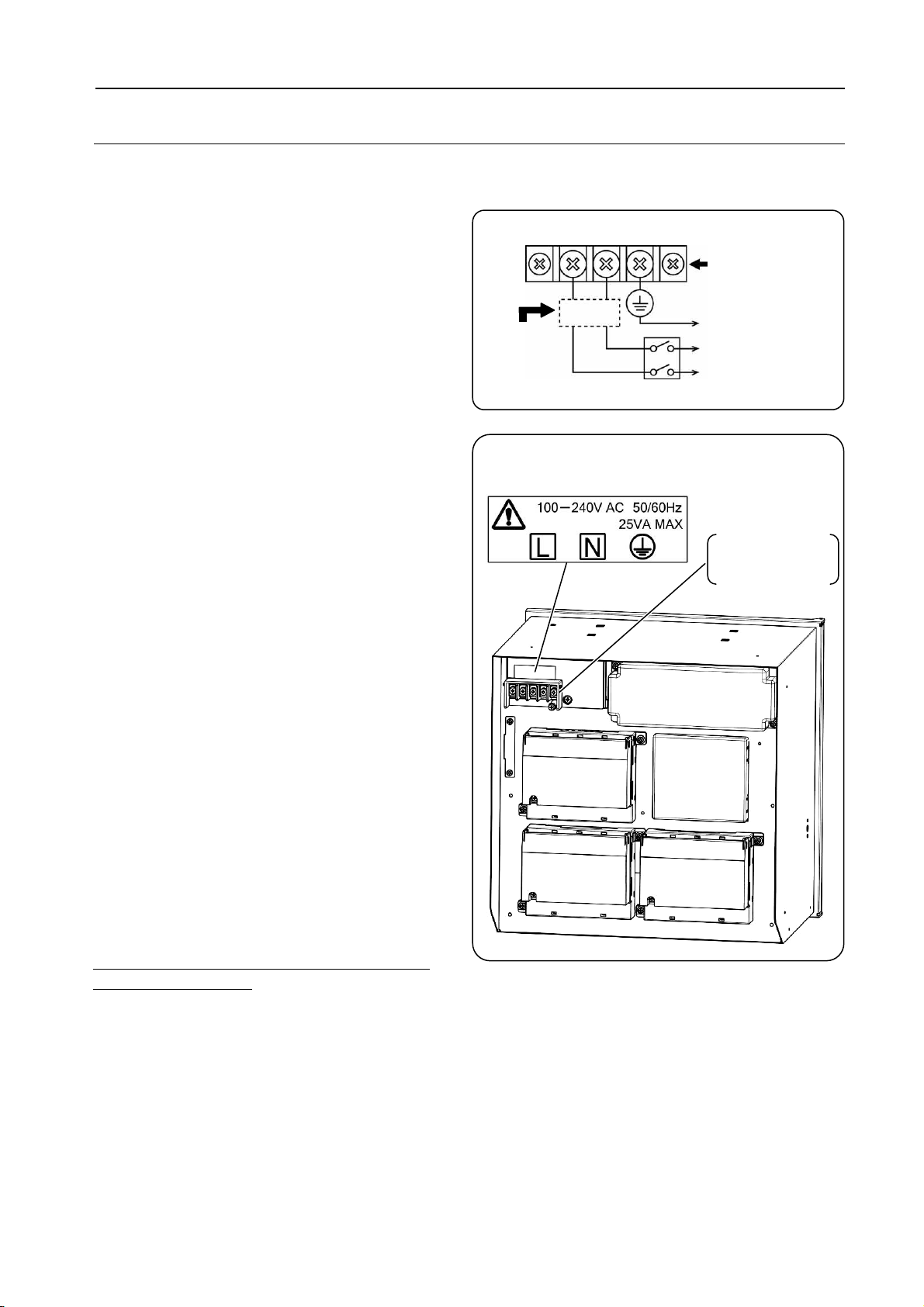
To avoid severe accidents, make sure to read and understand the following.
(1) Switch and Overcurrent Protective Device
This product is not provided with a replaceable overcurrent
protective device. Prepare an overcurrent protective device
[dot-printing type: 250, 2.5A/pen type: 250V, 3.15A] for the power
supply (circuit breakers, circuit protectors or the like) within 3m of
this unit in a location where the operator can access easily. Use a
switch and an overcurrent protective device conforming to
IEC60947-1 and IEC60947-3. Install a power switch to exterior if
necessary.
(2) Be Sure to Ground
To avoid electric shock, before turning the power on, connect the
protective conductor terminal of this product to the protective
conductor of the power supply equipment, and do not remove it
during use.
(3) Before Turning On the Power First
Make sure that the power voltage is within the range indicated on
the power label and grounding is done etc. before turning on the
power switch.
(4) Protection of the Terminals
For the terminals of this product, to avoid electric shock, install a
safety device so that user of this product will not touch the terminals
directly.
(5) Installing the safety device
Regarding the use of this product that anticipates a big loss due to
failure of the controller and the peripheral device, always install a
safety device for preventing these losses and implement fail safe
design in the final product.
Do not use it in important in facilities like, human life, atomic energy,
aviation and space.
(6) Do Not Put Hands in this Product
Do not put your hands or tools inside of this product. It may cause
electric shock or injuries.
There is no operation such as pulling out an inner unit or using
tools when using this product.
(7) Turn off the power supply if abnormality occurs
Turn off the power supply immediately and contact your local
CHINO’s sales office if any abnormal odor, noise or any smoke
occurs, or if this unit becomes high temperature that is too hot to
touch.
WARNING
Overcurrent
protective
device
[12 points] Specification example
(8) No Repair or No Modification
If repair or modification is necessary, contact your dealer or nearest
CHINO’s sales agent. Persons other than service engineers
authorized by our company must not repair or modify this product
with replacing parts.
(9) Use the unit following the instruction manual
For safe use, use the unit following the instruction manual. Please
note that CHINO does not have any responsibilities for any claims
for failures or damages occurred with abuse or misuse of this
recorder.
L N
Switch
Power label
Power supply/protective
conductor terminals
To protective
conductor of power
source facility
Power source
Power terminals
Protective conductor
terminal
-3-
Page 7
❐MAIN FEATURES AND FUNCTIONS
This product is intended to record the industrial quantities such as temperature, etc. on 180 mm-width chart paper. For the dot-printing
type, up to 12-channel recording and for pen type, up to 3-channel continuous recording is available.
(1) Features
Main features are as follows:
• Recording operation can be started without operations for setting or others depending on specified input conditions.
• Standard input type can be specified among 31 types (18 types for thermocouple, 6 types for DC voltage, and 7 types for resistance
thermometer).
The input type and scale width can be specified from 10 ranges of DC voltage, 26 ranges of thermocouple, and 6 ranges of
resistance thermometer other than standard input types.
• Universal power supply input is available. The measuring power voltage range is 100 to 240 VAC and 50 Hz/60 Hz.
• Any operations can be executed at the front. For inkpad replacement of the dot-printing type, pull out the inner unit to the position of
the middle stopper (it cannot be pulled out after the middle stopper position) then perform the replacement. For cartridge pen
replacement of the pen type, pulling out the inner unit is unnecessary.
(2) Functions
Main functions are as follows:
Display/operation related Instruction/recording related
Dot-printing
type
Pen type
Note 1: Setting of alarm values is required. The alarm output is available only by adding the option of “Alarm output”.
• Indication/recording operation and stop
• Chart speed selection switching
• Lighting of alarm lamp on the front on alarm
activation (Note 1)
• Chart paper lighting (standard provision and
dimming enabled)
• Function of indication adjustment at user area
(ZERO/SPAN adjustment and shift programming)
• Trend recording of 1 to 12 channels by dotter
• Mode for specified channels to be indicated continuously
without recording
• Continuous trend recording by the cartridge pen
• Individual indication/recording operation and switch of stop
by each pens
• Manual pen up lever for all pens correctively
(pen up is available when not recording)
-4-
Page 8
1. BEFORE USE
2
8
1.1 Model Check and Information
After unpacking of this product, make sure to confirm the following before usage. If you have any questions, contact your nearest
CHINO’s sales agent.
Checking item Checking contents Reference
1. Appearance The product has no damage in the appearance.
2. Model code The model code of the product that you purchased is correct. Para. 1.1
There is no shortage of the attachments.
Attachments may be provided separately depending on
3. Attachments
purchased options.
* For current input specification, shunt resisters that are same
numbers of input points are attached.
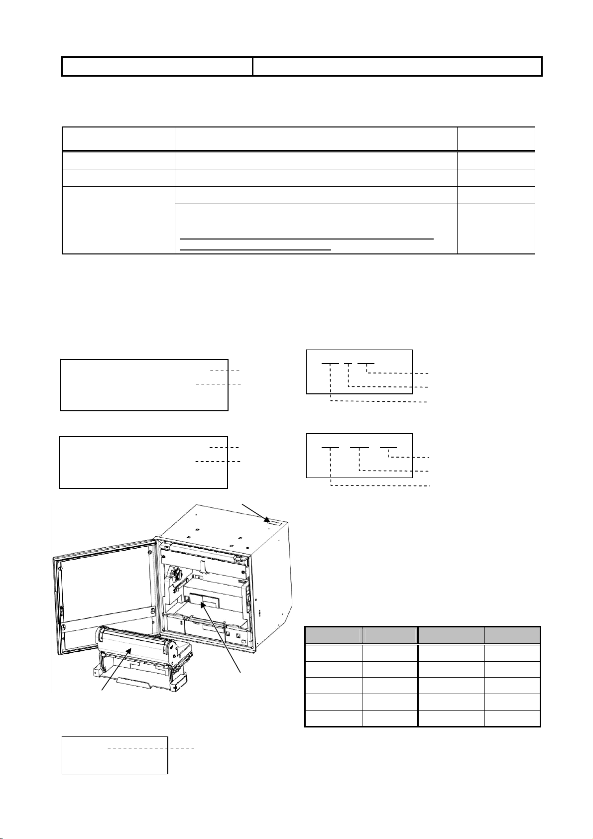
(1) Model Check
Labels indicating model are placed on the upper face of the case
(label 1) and the back of the inner unit which appears when a chart
cassette is pulled out (label 2).
(Refer to 5.2 Chart Loading (1) Drawing out Chart Cassette)
Example of label indication for dot-printing type
Example of label indication for pen type
The Label 2 consists of a label to indicate the model and a label to
indicate input specifications.
K4
EH3D65-000
EN103A001
MADE IN JAPAN
EH3G000-00
FN10XA001
MADE IN JAPAN
Chart cassette
Input code
Model
Serial No.
Model
Serial No.
Label 1
Label 2
Para. 1.
Para.
Input codes include particular codes for the factory administration
(Refer to 11.3 Accuracy Rating List. (1) Standard Input).
Non-standard input may be indicated with “XX”.
Indication example for dot-printing type, dual scale
K6 5 V6
Indication example for pen type (three pen specification)
K6- KC- V6
*The column other than input codes is blanked out.
2nd input code
2nd input starting channel
1st input code
3rd pen input code
2nd pen input code
1st pen input code
(2) Information
1) Chart Paper Attached
The chart paper No. EH01001 (0 to 100) is attached for operation.
For standard input specification, specified chart paper is available.
(Refer to 11.3 Accuracy Rating List (1) Standard Input Chart No)
Example for chart paper corresponding to various scales is shown
below:
Scale Chart No. Scale Chart No.
0 to 100°C EH05001 0 to 400°C EH05040
0 to 150°C EH05044 0 to 600°C EH05038
0 to 200°C EH05043 0 to 800°C EH05037
0 to 250°C EH05042 0 to 1000°C EH05036
0 to 300°C EH05041 0 to 1200°C EH05035
The scales are linear-equal divisions. They are usable irrespective
of the types of thermocouples and resistance thermometers.
For other chart papers, contact your nearest CHINO’s agent.
-5-
Page 9
1. BEFORE USE
1.1 Model Check and Information
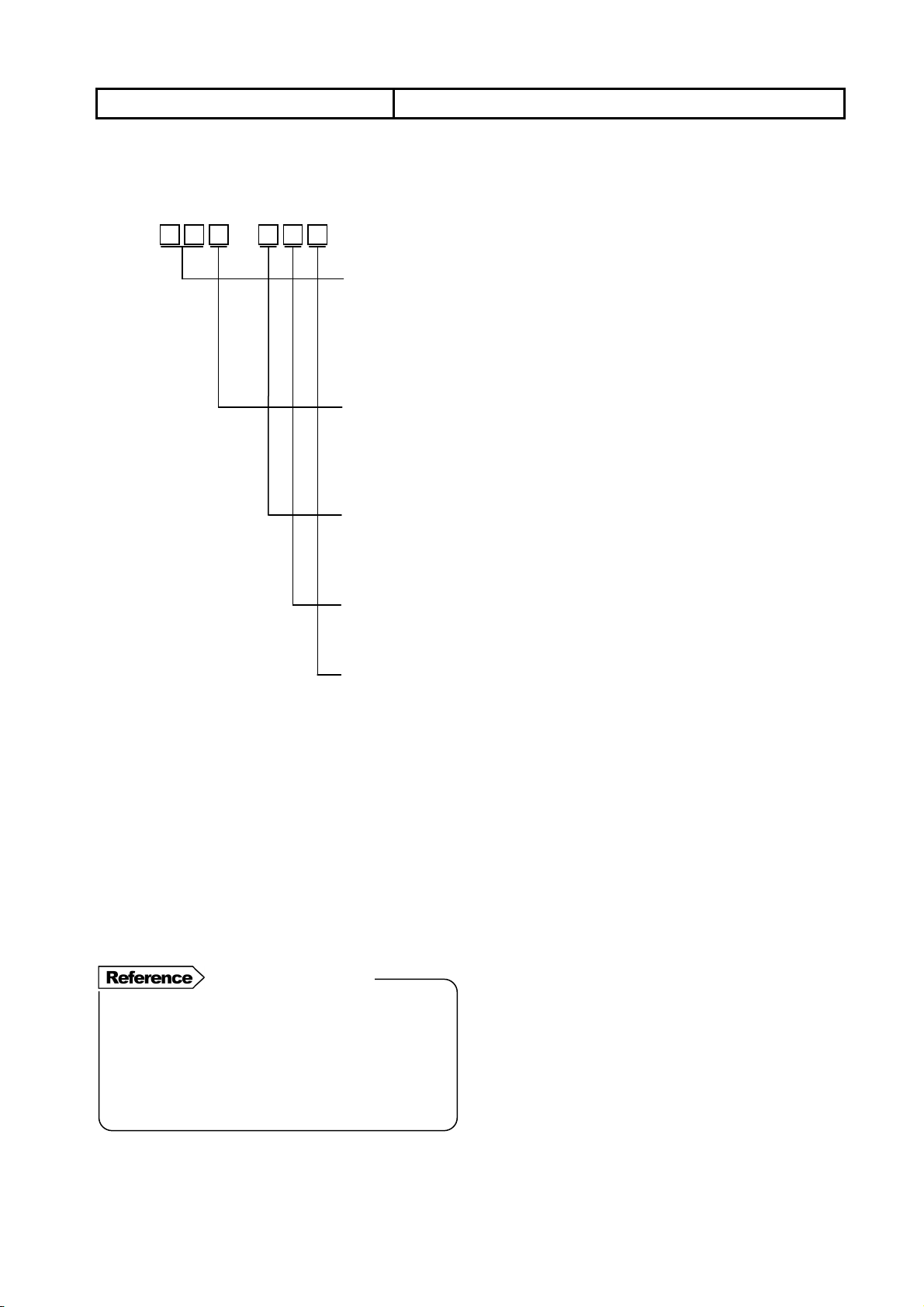
Models
[Dot-printing type]
EH3 —
Number of input points
D1: 1 point
D2: 2 points
D3: 3 points
D6: 6 points
12: 12 points
Input type
5: Thermocouple/DC voltage input
7: Resistance thermometer input
Thermocouple with burnout (optional) *1
DC voltage with built-in voltage divider input (optional) *1
Input and scale plate
0: Standard input + standard scale plate
1: Non-standard input (including current input and built-in voltage divider input)
Non-standard scale plate (optional) *2
Alarm output
0: None
2: Alarm output 2 points (optional))
Chart speed and burnout (optional) *3
0: Standard 6-speed/no specification of burnout
1: Standard 6-speed/Up-scale burnout (optional)
2: Standard 6-speed/Down-scale burnout (optional)
A: 5-speed with hour/minute changeover/no specification of burnout (optional)
B: 5-speed with hour/minute changeover/Up-scale burnout (optional)
C: 5-speed with hour/minute changeover/Down-scale burnout (optional)
*1: The options of built-in voltage divider and burnout for thermocouples/resistance thermometers are only available in the input type “7”.
*2: Up to triple scale is available.
For non-standard inputs and non-standard scale plates, specify an input type and scale.
*3: The burnout is specified for all input points together for thermocouple/resistance thermometer inputs.
The input type and scale plate are fixed with specified
specifications. They cannot be changed.
The contents of types described in the definition (“5” and “7”)
for input types are used for identification control in
manufacturing. Setting change and switching in the types are
disabled.
Input Type and Scale Plate
-6-
Page 10
1. BEFORE USE
1.1 Model Check and Information
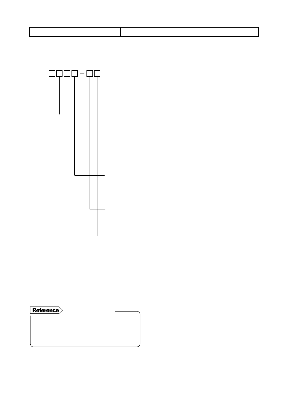
Models
[Pen type]
EH3
Number of input points
P: 1 pen
F: 2 pen
G: 3 pen
1st pen input and scale plate
0: Standard input + standard scale plate
1: Non-standard input (including current input and built-in voltage divider input)
Non-standard scale plate (optional) *1
2
nd pen input and scale plate
N: None (for 1 pen specification)
0: Standard input + standard scale plate
1: Non-standard input (including current input and built-in voltage divider input)
Non-standard scale plate (optional) *1
3 rd pen input and scale plate
N: None (for 1/2 pen specification)
0: Standard input + standard scale plate
1: Non-standard input (including current input and built-in voltage divider input)
Non-standard scale plate (optional) *1
Alarm output
0: None
2: Alarm output 2/4/6 points (optional)
(1 pen type: 2 output, 2 pen type: 4 output, 3 pen type: 6 output )
Chart speed and burnout (optional) *2
0: Standard 6-speed/no specification of burnout
1: Standard 6-speed/Up-scale burnout (optional)
2: Standard 6-speed/Down-scale burnout (optional)
A: 5-speed with hour/minute changeover/no specification of burnout (optional)
B: 5-speed with hour/minute changeover/Up-scale burnout (optional)
C: 5-speed with hour/minute changeover/Down-scale burnout (optional)
*1: For non-standard inputs and non-standard scale plates, specify an input type and scale.
If including the thermocouple input, make sure to specify the thermocouple input to the 1 st pen.
*2: The burnout is specified for all input points together for thermocouple/resistance thermometer inputs.
Input Type and Scale Plate
The input type and scale plate are fixed with specified
specifications. Specifications distinguished by models can not
be changed afterward.
Also change of input type and switching in input are disabled.
-7-
Page 11
1. BEFORE USE
1.2 Attachments and Consumable Parts
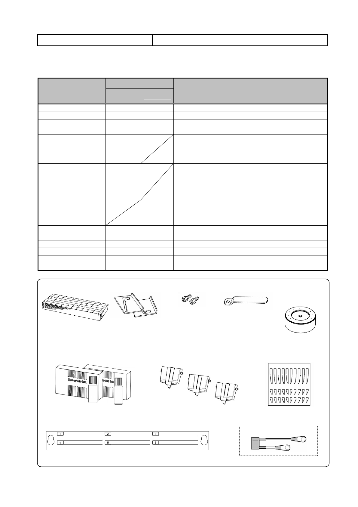
(1) Checking Attachments
The following attachments are contained. Check them.
Quantity
Part name
1. Chart paper 1 pad 1 pad Chart No. EH-01001: 0 to 100 (100 sections), no unit
2. Mounting bracket 2 pieces 2 pieces For mounting on a panel
3. Fixing screw 2 pieces 2 pieces For mounting brackets for panel mounting
4. Screw wrench 1 piece 1 piece For tightening fixing screws
5. Inkpad 1 piece
6. Supplementary ink
7. Cartridge pen
8. Channel indicating card 1 sheet 1 sheet
9. Alarm index seal 1 sheet 1 sheet When alarms are set, paste the seals on a scale plate for their indexes.
10. Instruction manual 1 book 1 book A4 book
* Shunt resister for current
input
1. Chart paper
* For current input specification, shunt resisters which are same numbers of input points are attached (refer to 8.1).
6. Supplementary ink
8. Channel indicating card (Example for 6 points)
Dot-printing
type
1 box
(1 to 6 points)
2 boxes
(12 points)
Number of current input point Shunt resister for current input.
2. Mounting bracket
Pen type
2 pieces for
each colors
Colors specified inkpad
(pull out the inner unit to the position of the middle stopper to perform
replacement)
Filled ink types depend on the specified number of input points.
Supplementary ink for inkpads
Ink which meets the specified input points attached.
7. Cartridge pen (for pen type)
1 point: 1 color x 6 pieces, 2 points: 2 colors x 3 pieces, 3 points: 3
colors x 2 pieces
6 points: 6 colors x 1 piece, 12 points: 12 colors x 1 piece
1 pen specification: 1st pen: red
2 pen specification: 1st pen: red, 2nd pen: green
3 pen specification: 1st pen: red, 2nd pen: green, 3rd pen: blue
Inserted inside the door
(Cards for 3 points/3 pen, 6 points, 12 points are available.)
3. Fixing screw
1st pen
2nd pen
3rd pen
Remarks
4. Screw wrench
*Shunt resister for current input
5. Inkpad
(for dot-printing type)
9. Alarm index seal
For dot-printing type/1 pen
For 2 pen/3pen
-8-
Page 12
1. BEFORE USE
1.2 Attachments and Consumable Parts
(2) Order of Consumable Parts
Chart papers and inkpads are consumable parts. For ordering these parts, refer to the following table.
Name Article name/specification for ordering Min.qty
Chart No. (Ex: EH01001)
Chart paper
Inkpad
Supplementary ink
Cartridge pen
For standard scale specification, refer to 11.3 Accuracy Rating List. (1) Standard
Input/Chart No.,
1-color inkpad (for 1 point): Stock No. 81-0230
2-color inkpad (for 2 points): Stock No. 81-0241
3-color inkpad (for 3 points): Stock No. 81-0252
6-color inkpad (for 6 points): Stock No. 81-0263
12-color inkpad (for 12 points): Stock No. 81-0274
1-color ink (for 1 point): Stock No. 83-0007
2-color ink (for 2 points): Stock No. 83-0166
3-color ink (for 3 points): Stock No. 83-0177
6-color ink (for 6 points): Stock No. 83-0133
12-color ink (for 12 points): Stock No. 83-0155
For 1st pen: Stock No. 82-0118
For 2nd pen: Stock No. 82-0129
For 3rd pen: Stock No.81-0130
1 box
(15 pads)
1 piece
1 box
(6 pieces)
1 box
(3 pieces/color)
1 box
(2 pieces/color)
1 box
(1 piece/color)
6-color x 2 boxes
(1 piece/color)
1 bag
(5 pieces)
-9-
Page 13
1. BEFORE USE
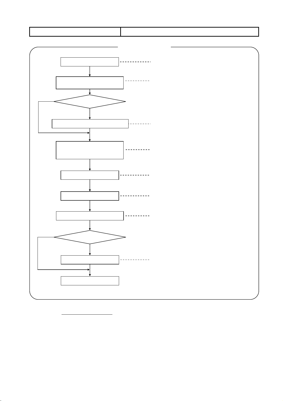
* The above is a simple flow chart to startup. Refer to each paragraph for details for actual work.
NO
Connection to alarm output terminals
NO
Panel mounting
Connection to power and
input terminals
Alarm output?
YES
Inkpad loading
Cartridge pen loading
Chart paper loading
Power ON
Chart speed change
Alarm setting?
YES
Alarm setting
Completed
1.3 Flow Chart to Startup
Flow Chart to Startup
Reference: 2.3 Mounting Method on Panel
Reference: 4.3 Power Supply & Protective
Conductor Terminals
Reference: 4.4 Measuring Input Terminals
Reference: 4.5 Alarm Output Terminals
Reference: 5.1 Inkpads Loading
Reference: 5.2 Cartridge Pen Loading
Reference: 5.3 Chart Paper Loading
Reference: 6.1 Turning Power On/Off
Reference: 6.6 Chart Speed Change
Reference: 6.8 Alarm Setting
-10-
Page 14
2. INSTALLATION
Place this instrument in the following place not to affect the measuring accuracy and recording operation adversely.
2.1. Mounting Place
(1) Industrial Environment
Select a place being separated from electric field and magnetic field generation sources and also free of mechanical vibrations and
shocks.
• Overvoltage category II (EN standard)
• Pollution degree 2 (EN standard)
• Altitude 2000 m or less
• Working place Indoors
(2) Environmental Temperature and Humidity
Avoid exposing this instrument to the direct sunlight, and avoid sealing around it to prevent temperature rise.
• It is desired to place it in where the ambient temperature is stable at about 23 °C and the humidity is stable at about 50 % RH.
• Place it in where free of being exposed to hot blast (70 °C or higher) and not exceeding the condition of ambient temperature (0 to
50 °C) for preventing failure and deformation of it.
• Place it in where being free of a heat source near its terminals and out of the wind for reducing measuring errors.
(3) Atmosphere
• Avoid using this instrument in an inflammable gas atmosphere for safety.
• Avoid using this instrument in any place where dust, smoke, vapor, and other substance exist.
• Substance example: Organic gas, Inorganic substances such as hydrogen sulfide and ammonia gas, and Low-molecular
siloxane
Mechanical relay is used for input switching of this product, and it may cause contact point failure with the above substances.
Many silicone-related materials include low-molecular siloxane; therefore, attention is necessary under the environment where
a lot of silicone-related adhesion bond, coating materials, and others are used. The low-molecular siloxane included in
adhesion bond and coating materials strips in the air for a certain period even during and after hardening.
If you are worried about impact of these substances, contact your nearest CHINO’s sales agent.
After the instrument is exposed in the atmosphere with even slight sulfur components for a long time period in the state of
power switch off, it may not be powered on even the power switch is turned on. This symptom occurs because sulfidizing film
generated on the connection surface of the power switch causes contact failure. If the power switch is turned on and off
several times, the generated sulfidizing film breaks and the instrument recovers.
However, if it is exposed in the atmosphere of sulfur components for a long time period, electronic parts other than the power
switch are affected and cause failures. Avoid using it in the atmosphere of even slight sulfur components.
Substances which Affect Instrument
Impact of Sulfurization by Sulfur Atmosphere
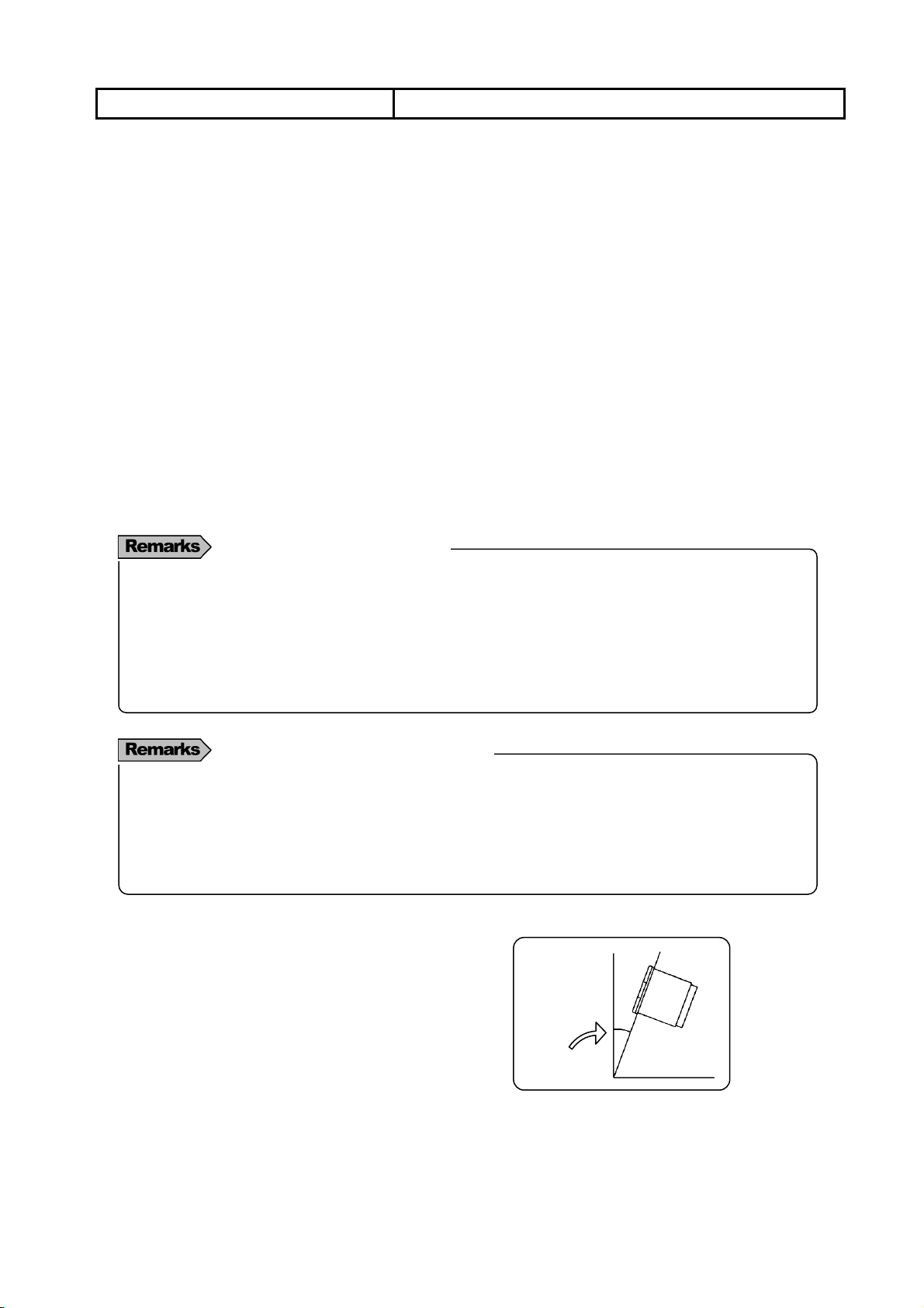
(4) Mounting Angle
• Lateral tilting: 0 to 10 degrees
• Longitudinal tilting: Forward tilting: 0 degrees
Backward tilting: 0 to 30 degrees
A mounting angle other than the specification above may affect
recording performance.
30 degrees or less
-11-
Page 15
2. INSTALLATION
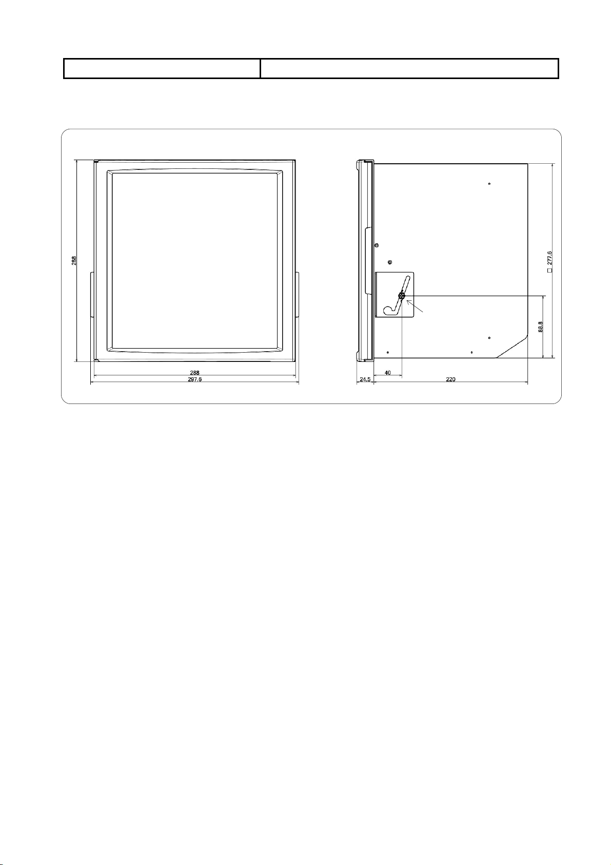
2.2 External Dimensions
(1) External Dimensions
• The following figures show the external dimensions with mounting brackets attached.
External dimensions
Mounting holes for fixing screws for
mounting brackets
(2 locations for left and right)
-12-
Page 16

2. INSTALLATION
1
Use it by mounting it on a panel installed indoor.
Use a panel of steel plate with the thickness of 2 to 6mm or a material with equivalent strength.
Select the thickness of the panel to be used according to weight and depth of the instrument and panel structure.
Use This Instrument by Mounting It on a Panel.
2.3 Mounting Method on Panel
(1) Panel Cutout Size
Standard mounting
±1
281
281
Panel cutout
(2) Mounting Method
1. Insert this instrument into the cutout from the front of the panel.
2. Screw lightly the attached fixing screws into the screw holes
(one hole in each side) of both sides of the case (Figure
below).
3. Insert the hexagon head of the mounted fixing screws into the
round hole of the attached mounting brackets from the both
sides of the case.
4. Like the figure below, slide down the mounting bracket, press
this instrument to the panel from the front for close attachment,
and tighten up the fixing screws with the attached screw
wrench (tightening torque: 2 N・m Figure right).
* The mounting bracket differs between ones for the right and
the left.
The mounting bracket in the figure above is for the right
side from the front.
Panel
Fixing screw
Slide down the mounting
bracket.
Min. clearance for mounting multiple units
±
Unit: mm
Panel cutout
360
360
Panel thickness (2 to 6 mm)
Panel Mounting of Instrument
For mounting the instrument on a panel, it must be carried
out by two persons or more for safety.
Unit: mm
Fixing screw
Mounting bracket
-13-
Page 17
2. INSTALLATION
2.4 Release of Shipping Status
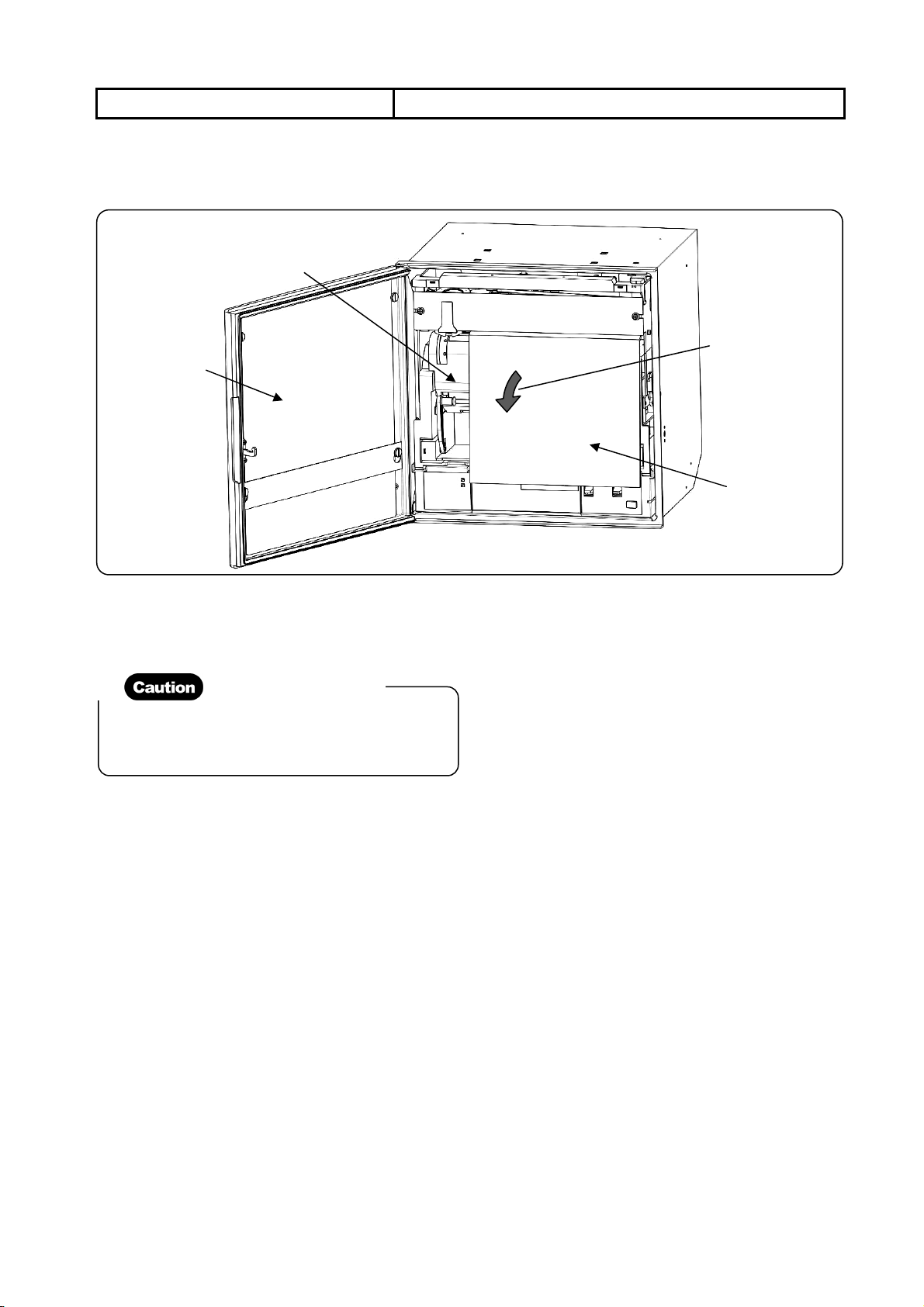
(1) De-installation of Fixing Paper
A fixing paper is installed inside the instrument to prevent damage (damage to the front glass and to recording mechanism) on
transportation (Figure below). It is for the inner unit so as not to fall out and for the recording mechanism so as to be fixed.
[Dot-printing type]
1. Pull down the fixing paper straight tilting it slightly. Do not pull it
2. Store the removed fixing paper with the shipping box.
Door
hard, but pull it out slowly and gradually.
Removing of Fixing Paper
Avoid pulling it upward, downward, or toward you.
When removing, do not pull by force. If it is pulled forcedly,
the instrument may be damaged.
Chart cassette
Direction for Fixing
Paper to be pulled out
Fixing paper
-14-
Page 18
2. INSTALLATION
2.4 Release of Shipping Status
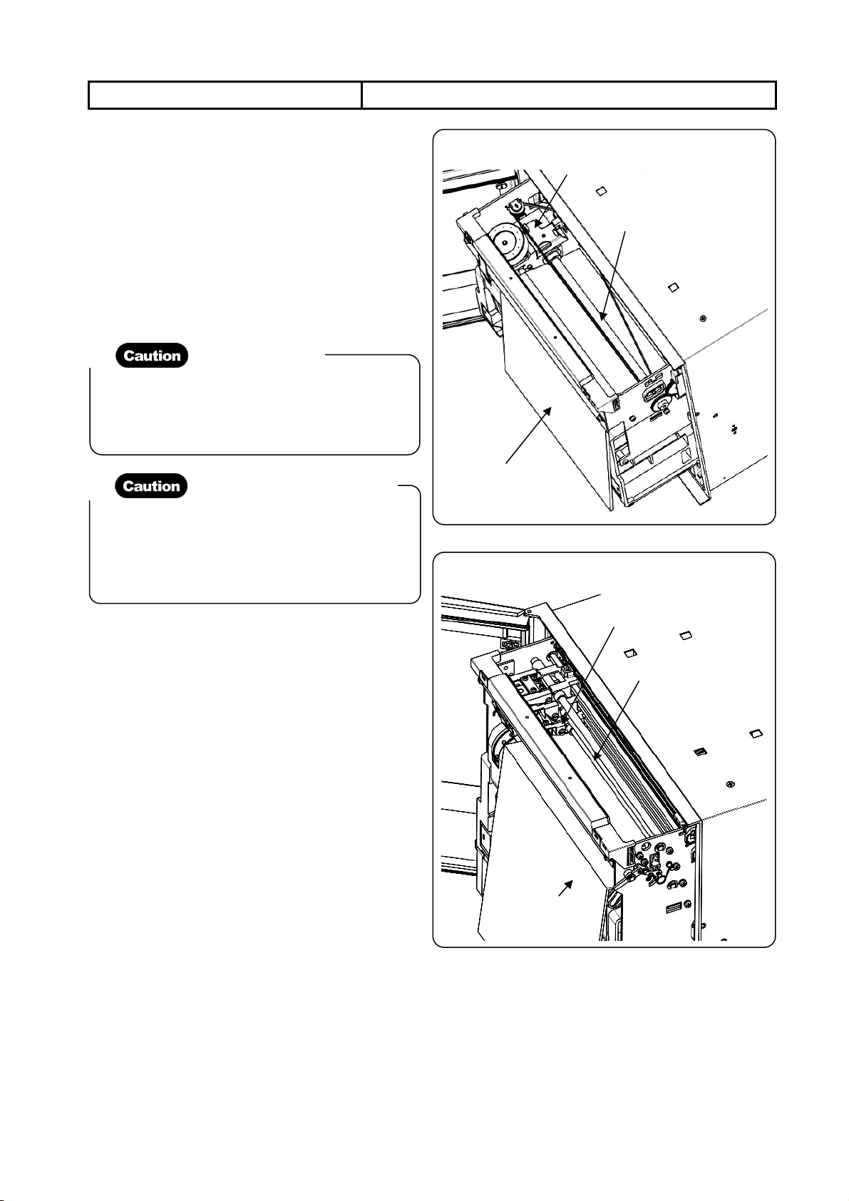
(2) Handling on Reshipping
1. On reshipping, the inkpad/cartridge pen must be removed.
2. Pull put the inner unit. (Refer to 5.1 Inkpad Loading )
z For the multi-point type, insert the fixing paper through under
the main shaft. as shown in figure right (Top view).
z For the pen type, insert the fixing paper through under the
lowest part of the main shaft, just above the chart cassette as
shown in figure lower right (Top view: three pen specification).
3. Check that an inner unit lock lever is open (inner unit is fixed).
Packing on Reshipping
When this product is reshipped, pack it in the state same as
when it was delivered to you. If it is packed in the different
state, it may be damaged by shocks and others on
transportation.
Caution on Installation of Fixing Paper
When moving the dotting mechanism and pen mechanism,
hold the part which fixes and move it quietly. If it is moved by
force or moved holding other parts, it may be damaged.
When the dotting mechanism and pen mechanism are moved,
the chart paper lighting may shine; that is not abnormal.
[Top view: dot-printing type]
Fixing paper
[Top view: pen type (three pen specification)]
Dotting mechanism
Main shaft (rotation shaft)
* Insert the fixing paper
1st pen pen mechanism
through under the main
shaft.
The lowest part of the
main shaft
*Insert the fixing paper
through under the
main shaft (of the 1st
pen).
Fixing paper
-15-
Page 19

3. FRONT
3.1 Names of Front Portions
(1) Front Part
All operations of this instrument including loading of the chart paper and inkpad/cartridge pen can be done from the front.
[Dot-printing type]
Door
How to Handle the Door
The front of the door is made of glass. Avoid giving any shock to the glass or giving any strong force to the frame for preventing
any injury due to breakage.
1. Chart Cassette
For loading the chart paper, draw out the chart cassette (Refer to
5.3 Chart Paper Loading.).
2. Display Operation Part
Operate each switch when operation and programming are
executed (Refer to 3.2 Display Operation Part.).
Open the front cover and operate various setting/operation keys
excluding AUTO CH/INDICATE switch, RECORD switch, and
FEED key (To open the cover, pull the convexity in left-of-center
of the front cover top.).
State of front cover opened
Scale plate
Front cover
Channel indicating card
Setting/operation
keys
Chart paper lighting
Power switch
1. Chart cassette
Chart feed gear
Front chart holder axis
Handle
3. Inner unit lock lever
2. Display operation part
3. Inner Unit Lock Lever
Pull out the inner unit for inkpad loading or replacement (For
dot-printing type).
Operate the inner unit lock lever and pull out the inner unit about
6 cm long (Refer to 5.1 Inkpad Loading.). When the inner unit is
pulled out about 6 cm long, it stops with the middle stopper.
It cannot be pulled out more than the middle stopper position.
The inner unit does not have to be pulled out for other than
inkpad loading or replacement.
(2) Channel Number Indication (dot-printing type)
Currently indicated channel number of input can be checked with
the channel number indication of dotter.
Example of Indication Channel “1”
Dotter channel
number indication
Indication channel
-16-
Page 20
3. FRONT
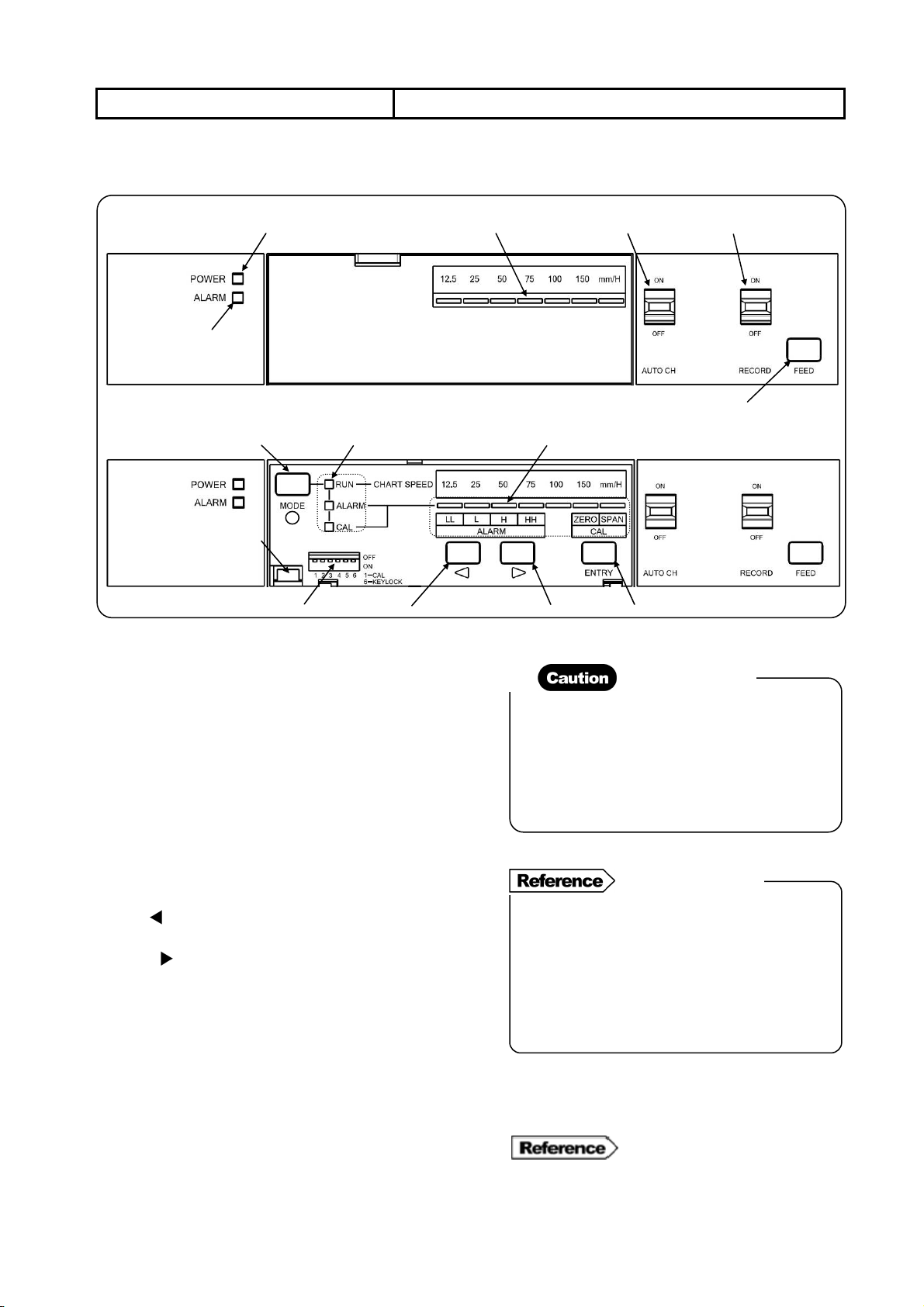
3.2 Display Operation Part
[Dot-printing type]
Detail of Display Operation Part
(1)
1) State of front cover closed
ⅱ
{
2) State of front cover opened
(*1) Engineering connector
Alarm
B
{
MODE
{
3
DIP switch
ⅰ
{
Power supply
(*2)
ⅲ
{
Chart speed
iv
{
Setting mode {vSetting parameter (only during Setting mode)
C
{
Left
(2)
Function of Display Operation Part
1. Switch
1
{
AUTO CH: Switching of Recording mode/1-point indication
mode
2
{
RECORD: Switching of ON/OFF of Indication/Recording
3
{
DIP switch: Refer to 6.2 Operation/Setting Change (3) DIP
Switch Function.
2. Setting/operation key
A
{
FEED: Feeding of chart papers with key operation
B
{
MODE: Operation on transition to Setting mode
C
{
Left ( ): Switching/selection operation on various
operation/setting
D
{
Right ( ): Switching/selection operation on various
operation/setting
E
{
ENTRY: Fixing operation for selection parameters on
various setting
3. Indication lamp
ⅰ
{
Power supply: Indication of power supply On/Off
ⅱ
{
Alarm: Indication of alarm occurrence (for all channels)
ⅲ
{
Chart speed: Indication of chart speed and unit
iv
{
Setting mode: Indication of various setting modes
v
{
Setting parameter: Indication of selection parameters on setting mode
(Chart speed lamp is used also for this purpose.)
(*1) Engineering connector is for maintenance. It is not used -on normal
operation.
1
{
AUTO CH
D
{
Right
Front Cover Protection
Avoid closing the door in the state of front cover opened.
If the door is closed in the state of the front cover opened,
the mechanism of the front cover allows the cover to be
lifted to the direction for closing to prevent damage;
however, behavior for protection is not guaranteed. If the
door is closed forcedly or fast, it may be damaged.
Setting information and various statuses information of
the instrument is stored in the nonvolatile memory
(EEP-ROM) within the instrument.
When the setting information of the instrument is
changed, the alarm lamp blinks for about 3 seconds.
When the status information of the instrument is changed,
the alarm lamp blinks for about 1.5 seconds.
(*2) it is a screw hole for front cover fixing. It is not used on
normal specification (refer to 6.9 Operation Setting Function
Depending on Application (2) Key Lock Function
2
{
RECORD
A
{
FEED
E
{
ENTRY
Blinking of Alarm Lamp
Another Key Lock Method).
-17-
Page 21
3. FRONT
3.2 Display Operation Part
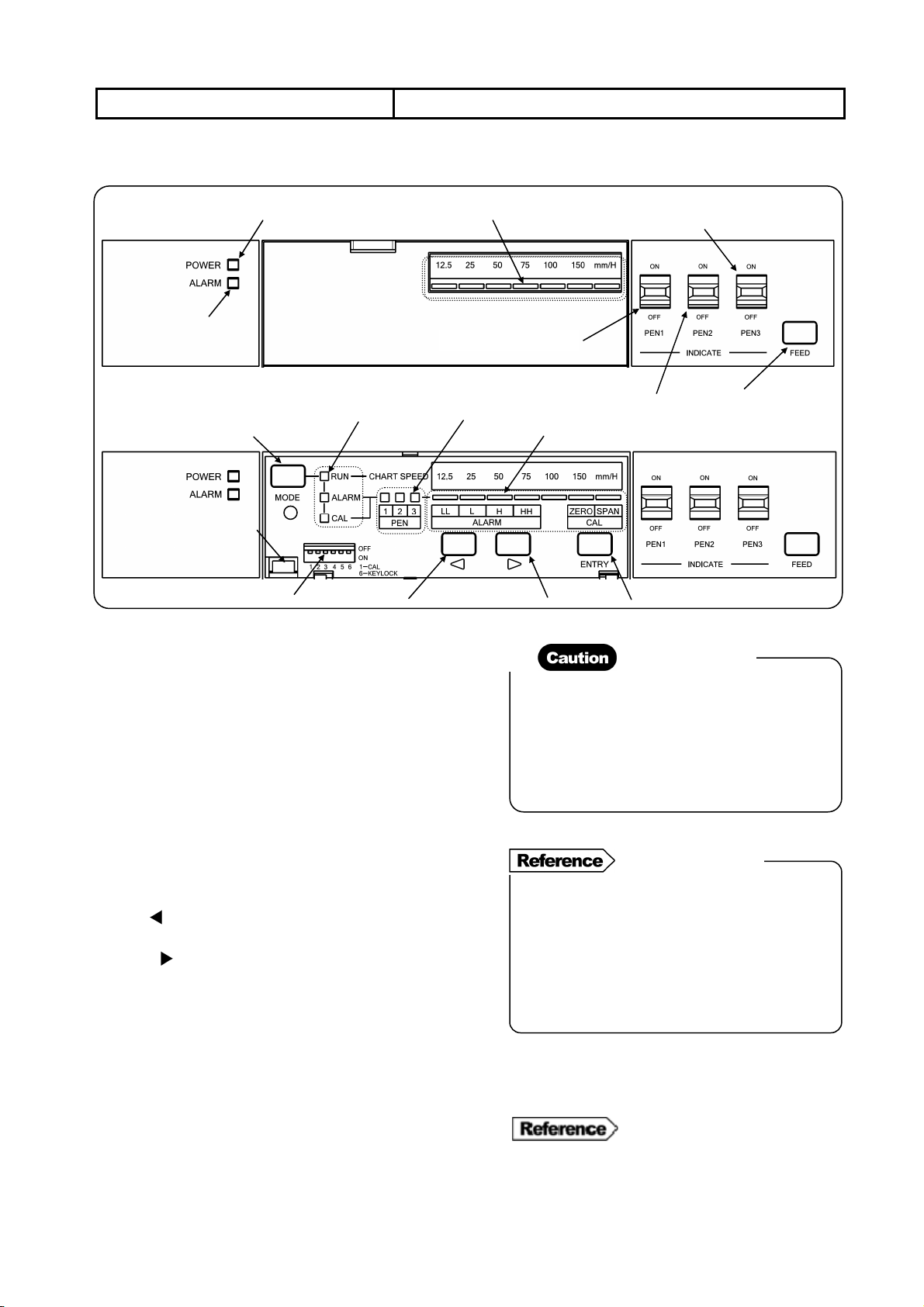
[Pen type]
Detail of Display Operation Part
(1)
1) State of front cover closed
(*1) Engineering connector
ⅱ
{
2) State of front cover opened
Alarm
B
{
MODE
○4DIP switch
ⅰ
{
Power supply
(*2)
iv
{
Setting mode
C
{
Left
ⅲ
{
Chart speed
1
{
1st pen INDICATE
○viPen selection
(2) Function of Display Operation Part
1. Switch
1
{
1st pen INDICATE: Switching of ON/OFF of Indication/Recording of
the 1st pen
2
{
2nd pen INDICATE: Switching of ON/OFF of Indication/Recording of
the 2nd pen
3
{
3rd pen INDICATE: Switching of ON/OFF of Indication/Recording of
the 3rd pen
○4 Refer to 6.2 Operation/Setting Change (3) DIP Switch Function
2. Setting/operation key
A
{
FEED: Feeding of chart papers with key operation
B
{
MODE: Operation on transition to Setting mode
C
{
Left ( ): Switching/selection operation on various
operation/setting
D
{
Right ( ): Switching/selection operation on various
operation/setting
E
{
ENTRY: Fixing operation for selection parameters on
various setting
3. Indication lamp
ⅰ
{
Power supply: Indication of power supply On/Off
ⅱ
{
Alarm: Indication of alarm occurrence (for all channels)
ⅲ
{
Chart speed: Indication of chart speed and unit
iv
{
Setting mode: Indication of various setting modes
v
{
Setting parameter: Indication of selection parameters on setting mode
(Chart speed lamp is used also for this purpose.)
○vi Pen selection: Indication of selection pen number on setting mode.
(*) Engineering connector is for maintenance. It is not used on normal operation.
3
{
3rd pen INDICATE
2
{
2nd pen INDICATE
v
{
Setting parameter (only during Setting mode)
D
{
Right
Front Cover Protection
Avoid closing the door in the state of front cover opened.
If the door is closed in the state of the front cover opened,
the mechanism of the front cover allows the cover to be
lifted to the direction for closing to prevent damage;
however, behavior for protection is not guaranteed. If the
door is closed forcedly or fast, it may be damaged.
Setting information and various statuses information of
the instrument is stored in the nonvolatile memory
(EEP-ROM) within the instrument.
When the setting information of the instrument is
changed, the alarm lamp blinks for about 3 seconds.
When the status information of the instrument is changed,
the alarm lamp blinks for about 1.5 seconds.
(*2) it is a screw hole for front cover fixing. It is not used on
normal specification (refer to 6.9 Operation Setting Function
Depending on Application (2) Key Lock Function
E
{
Blinking of Alarm Lamp
Another Key Lock Method)
ENTRY
{
A
FEED
.
-18-
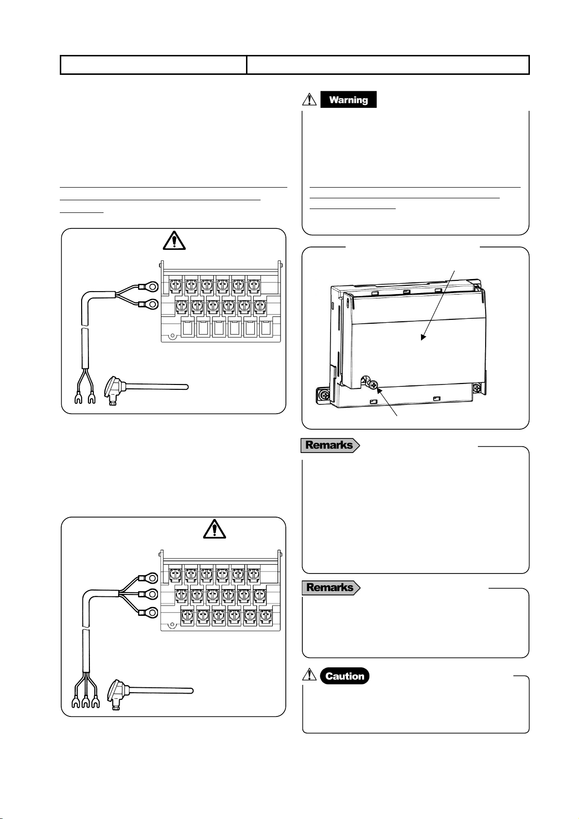
Page 22
4. CONNECTIONS
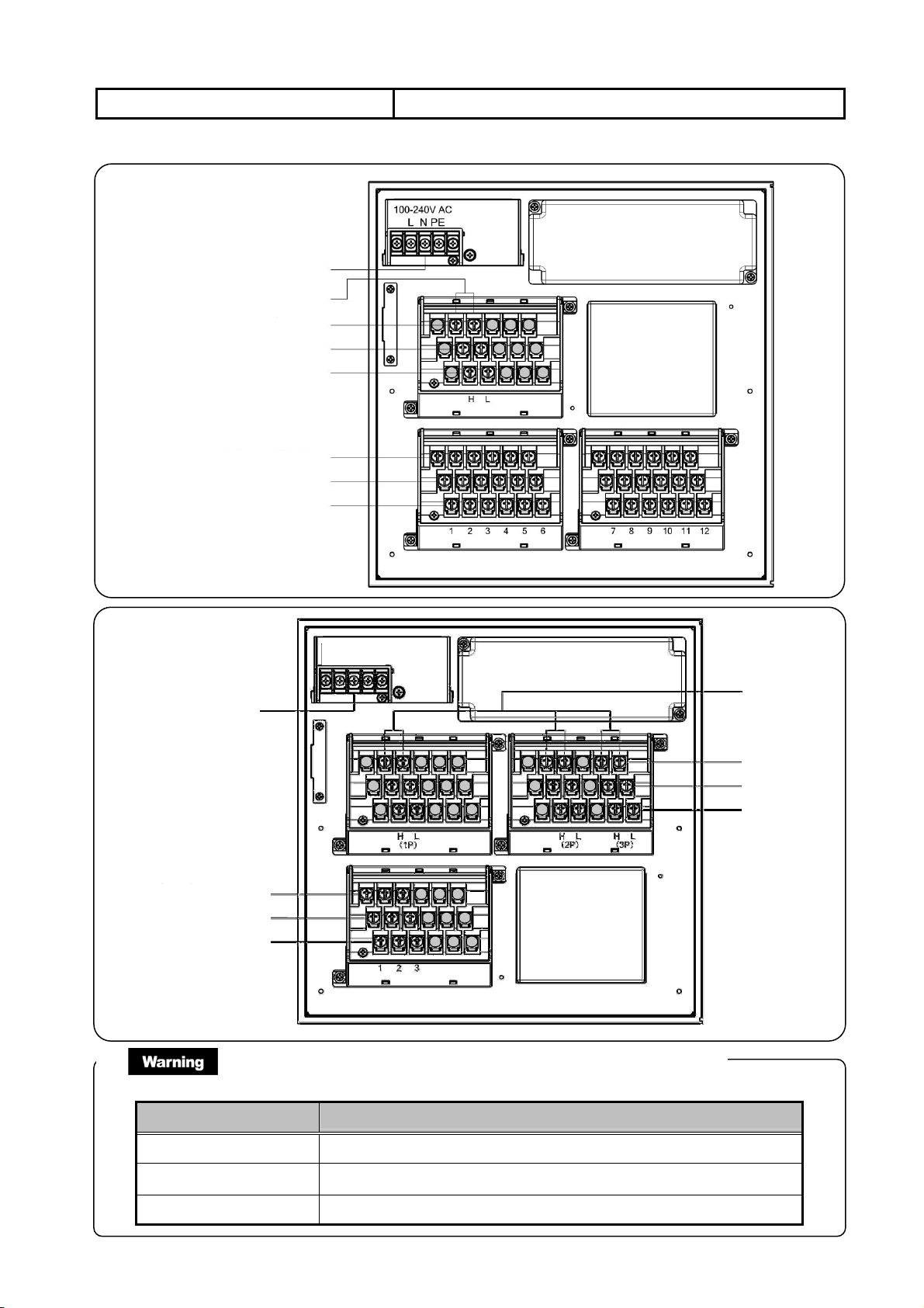
The figure below shows the terminal board with option (alarm output).
[Dot-printing type]
(12 points specification) example
[Pen type]
(3 pen specification)
example
Power supply/protective
Conductor terminals (M4)
Measuring input terminals (M4)
TC mV (+), RTD (A) terminals
TC mV (-), RTD (B) terminals
The symbol marks are pasted on the locations where electric shock may occur if touched (Table below).
Power supply/protective
conductor terminals (M4)
Alarm output terminals (M4)
Measuring input terminals (M4)
TC mV (+), RTD (A) terminals
TC mV (-), RTD (B) terminals
RTD (b) terminals
(Optional)
N.O terminals
COM terminals
N.C terminals
RTD (b) terminals
Alert Symbol Marks () and Places
Name of terminal
Power terminals Top of the power terminals
Measuring input terminals Top of the measuring input terminal cover
Alarm output terminals Top of the alarm output terminal cover
4.1 Terminal Board
mark pasted location
-
Alarm output
terminals (M4)
(Optional)
N.O terminals
COM terminals
N.C terminals
-19-
Page 23
4. CONNECTIONS
The following are cautions before connections. Make sure to observe them for securing safety and reliability.
(1) Power Source
Use a single-phase power that has a stable voltage and no
distorted waveform to prevent the wrong operation.
Switch and Overcurrent
Add a switch and overcurrent protective device
(multi-point type: 250 V, 2.5 A/pen type: 250V, 3.15A)
to the power source for preventing an electric shock
during connection work.
This product has no replaceable fuse.
Turn off the Power Source
Before connecting to the power supply and
input/output terminals, make sure to turn off the power
source for preventing an electric shock.
(2) Keep away from Strong Power Circuit
Avoid placing the input/output cables to be close to or in
parallel with any strong power circuits including power line.
Keep them more than 50 cm away from the circuits if close
to or in parallel with the circuits.
(3) Keep away from Heat Source
(Thermocouple Input)
For thermocouple inputs, keep the terminals away from a
heat source (a material generating heat) for reducing an
error of reference junction compensation. In addition,
avoid exposing the terminals to the radiation of direct
sunlight or place them where wind blows.
Protective Device
before Connections.
4.2 Cautions on Connection
(4) Avoid Noise Source
Keep connection cables from a noise source as far as
possible. Otherwise an unexpected trouble may occur.
Take a remedial measure if the cables cannot be kept
away from a noise source.
Major noise source Measure
Electromagnetic switch
Power line having distorted
waveform
Inverter
Thyristor regulator
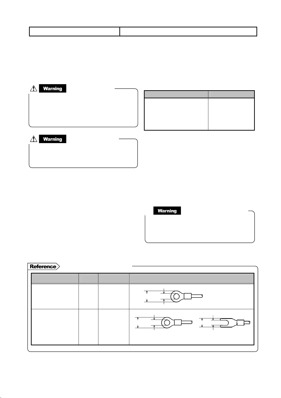
(5) Use Crimp Style Terminals
1. Mount a crimp style terminal as a connection cables’
termination for preventing the looseness or
disconnection of terminals and a short-circuit failure
between terminals.
2. For the crimp style terminal, use an insulation sleeve for
preventing an electric shock.
(6) Unused Terminals
Avoid using any unused terminals for relaying. Otherwise,
electric circuits may be damaged.
Treat connected cables securely so as not to allow
them to be hooked by a person or a substance.
Otherwise, the connections may be disconnected or
cut and cause an electric shock or other accidents.
Treat Connected Cables Properly
Insert noise filters
between the power
supply and
input/output
terminals.
Terminal board Dia. Torque Termination (Unit: mm)
Power
supply/protective
conductor terminals
Terminals other than
the above
Types of Terminals and Termination
M4 1.2N•m
M4 1.2N•m
8.5 or less
8.5 or less
Use of “O-chip (left side)” recommended.
-20-
4.3 or more
4.3 or more
t: 0.8 with insulation sleeve
8.5 or less
t: 0.8
with insulation sleeve
4.3 or more
Page 24
4. CONNECTIONS
r
A
A
y
(1)
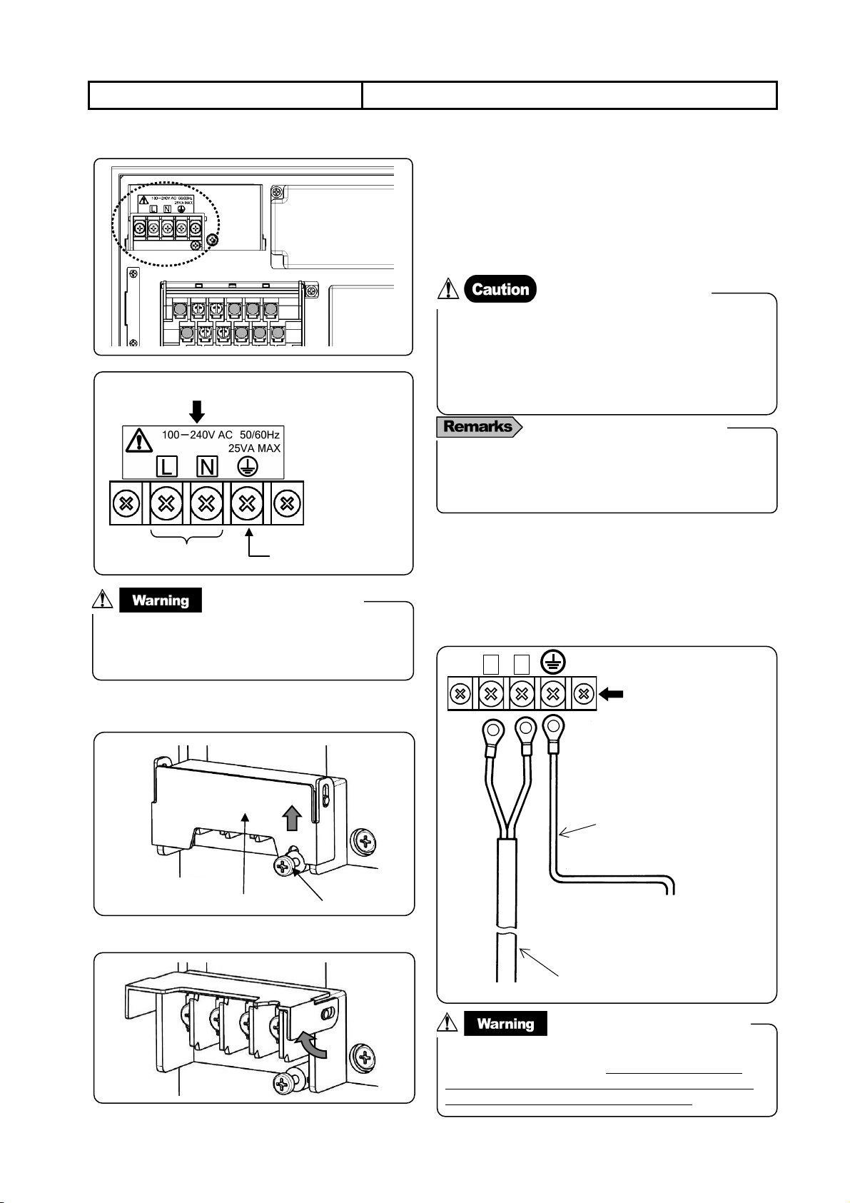
Power Supply/Protective Conductor Terminals
P/S (Voltage, frequency, and power consumption):
Before connecting to the power supply and protective
conductor terminals, make sure to turn off the power
source for preventing an electric shock.
1. Loosen the fixing screw of the power terminals cover.
2. Slide the cover up.
Power terminals cove
3. Open the cover up until horizontal position.
displa
Power terminals
example of dot-printing type
Protective conductor
terminal
Turn off the Power Source.
4.3 Power Supply & Protective Conductor Terminals
Fixing screw
(2)Connection to Power Terminals
For the connection to power terminals, use a 600 V vinyl
insulated cord (Note 2) with the crimp style terminals and
an insulation sleeve.
Note 2: Use the cords approved by the following
standards.
1) IEC 60227-3
2) ANSI/UL817
3) CSA C22.2 No. 21/No. 49
Be Careful with the Power
The power voltage of this product is indicated beside the
power terminals.
Avoid applying any voltage other than indicated,
otherwise a serious accident occurs or malfunction
results. In addition, if noises are mixed into the power,
take a remedial measure, such as the addition of a
noise cut transformer, etc.
These are indications according to CSA Standard,
Canada. L is for single-phase AC power, and N is for
neutral. To secure the performance of this instrument,
connect the terminals appropriately.
(3)
Connection to Protective Conductor Terminals
Make sure to connect this terminal to the protective
conductor of the power source facility. For this connection,
use a cable with a crimp style terminal with an insulation
sleeve.
• Grounding wire: A copper wire having a wire diameter
of larger than 2 mm
L N
Power supply
A voltage of 100 to 240 VAC is applied to the power
terminals after connections. Make sure to close and
mount the power terminal cover with a screw after the
connection for preventing an electric shock.
Voltage and Noises.
L/N Indication of Power Terminals
2
(green/yellow)
fter connections,
mount the terminal
cover with screws.
copper wire having a wire
diameter of larger than 2
2
(green/yellow)
mm
Make sure to connect this terminal
to the protective conductor of the
power source facility.
600 V vinyl insulated cable
-marking on Power Terminals
-21-
Page 25
4. CONNECTIONS
4.4 Measuring Input Terminals
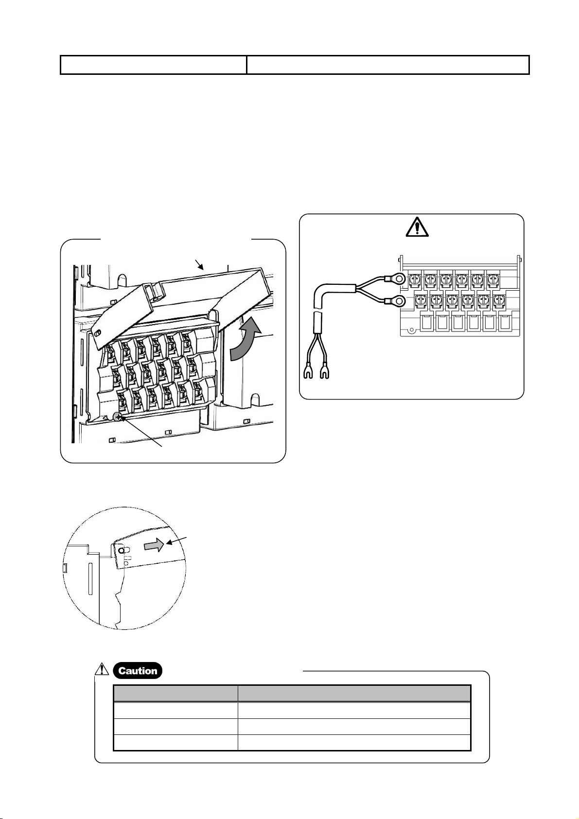
(1) Connection of Measuring Input Terminals
Make sure to turn off the power source before connection for
preventing an electric shock.
1. Loosen the fixing screw of the input terminals cover and slide the
cover up.
2. Open up the input terminals cover slightly (the cover is removed
from fixing screw) and slide back down (prior to the slide up
position).
3. In the state of slid down position, open the cover up until it stops
(Figure below).
4. The input terminals cover stops at middle position easily (Refer to
figure below: side view).
5. For this connection, use a cable with a crimp style terminal with
an insulation sleeve for the input terminal.
State of Input Terminals Cover Opened
Input terminals cover
Fixing screw
The input terminals cover
stops easily when slided to
the direction of an arrow.
Maximum Permissible Input Voltage
Voltage and thermocouple input ±10VDC or less (Input scale of ±5V or less)
Resistance thermometer input ±6VDC or less
Input type Permissible input voltage
Voltage-divided input ±60VDC or less (Input scale of exceeding ±5V)
(2) Connection of DC Voltage (Current) Input
Use a twisted cable for instrumentation as the input cable for
suppressing noises.
For the current input (optional), mount a shunt resistor for current
input (Refer to 8.1 Shunt Resister for Current Input) to the channel
to be measured before connections.
Avoid using this instrument in parallel with other instruments,
otherwise troubles may occur (Indication fluctuation, indication
errors, and others may occur.).
z DC voltage (current) input
Twisted cable for
instrumentation
DC voltage input
123456
(+)
(-)
Channel
-22-
Page 26
4. CONNECTIONS
A
4.4 Measuring Input Terminals
(3) Connection of Thermocouples (TC) Input
Use a thermocouple wire (or compensation lead wire) to the input
terminals of this instrument. If a copper wire is used halfway, a
noticeable measuring error occurs.
Avoid using a pair of thermocouple wires in parallel with the other
instruments (controllers, etc.), otherwise troubles may occur
(Indication fluctuation, indication errors, and others may occur.).
If the instrument has the burnout function (optional), avoid using it in
parallel with other instruments (otherwise it may affect other
instruments).
• Thermocouple (TC) input
Compensation
lead wire
Red (+)
White (-)
123456
Thermocouple
Channel
(4) Connection of Resistance Thermometer (RTD)
Input
For preventing measuring errors, use a 3-core code of which each
wire has equal resistance value.
Avoid using one resistance thermometer in parallel with other
instruments (controllers, etc.).
• Resistance thermometer (RTD) input
3-core cord
(Same diameter and length)
B
b
Note: The resistance value for one code is
Resistance thermometer
123456
10Ω or less. Use 3 codes which have
the equal resistance value.
Channel
A high voltage may be applied to the measuring input
terminals due to common mode noise (common mode voltage
applied between the measuring input terminal and protective
conductor terminal). The tolerance of the common mode
voltage is 30VAC or 60VDC or less. Make sure that the
common mode voltage is lower than the tolerance.
Make sure to close and mount the terminal cover with a screw
after the connection for preventing an electric shock and
protection of input cables. Closing and mounting the terminal
cover allows reducing errors of reference junction
compensation.
For the terminals for DC voltage and thermocouple input,
channels are insulated (functional insulation, Note 3); however,
for the terminals for resistance thermometer, channels have
equal potential (All b terminals are connected within the
instrument.).
Note 3) Functional insulation: Insulation necessary for normal
operation of instruments without protective function against
electric shocks (avoiding ground loop formulation of
instruments)
If input is opened in the state of no burnout function,
indication/recording values become unstable.
Indication/recording may be placed in the lower limit position, or
in the higher limit position temporarily; however, that state is not
guaranteed.
Input Terminals for 1-, 2-, 3-point Types
The input terminals arrangements for 1-, 2-, 3-point type
specification and pen type differ. Refer to the input terminals
diagram on the back of the instrument and (5) Measuring Input
Terminals Arrangement mentioned later.
Fixing of the Input Terminals Cover
Insulation between Channels of
Measuring Input Terminals
Indication/recording on Input Open
-marking on Measuring Input Terminals
Input terminals cover
Fixing screw
-23-
Page 27
4. CONNECTIONS
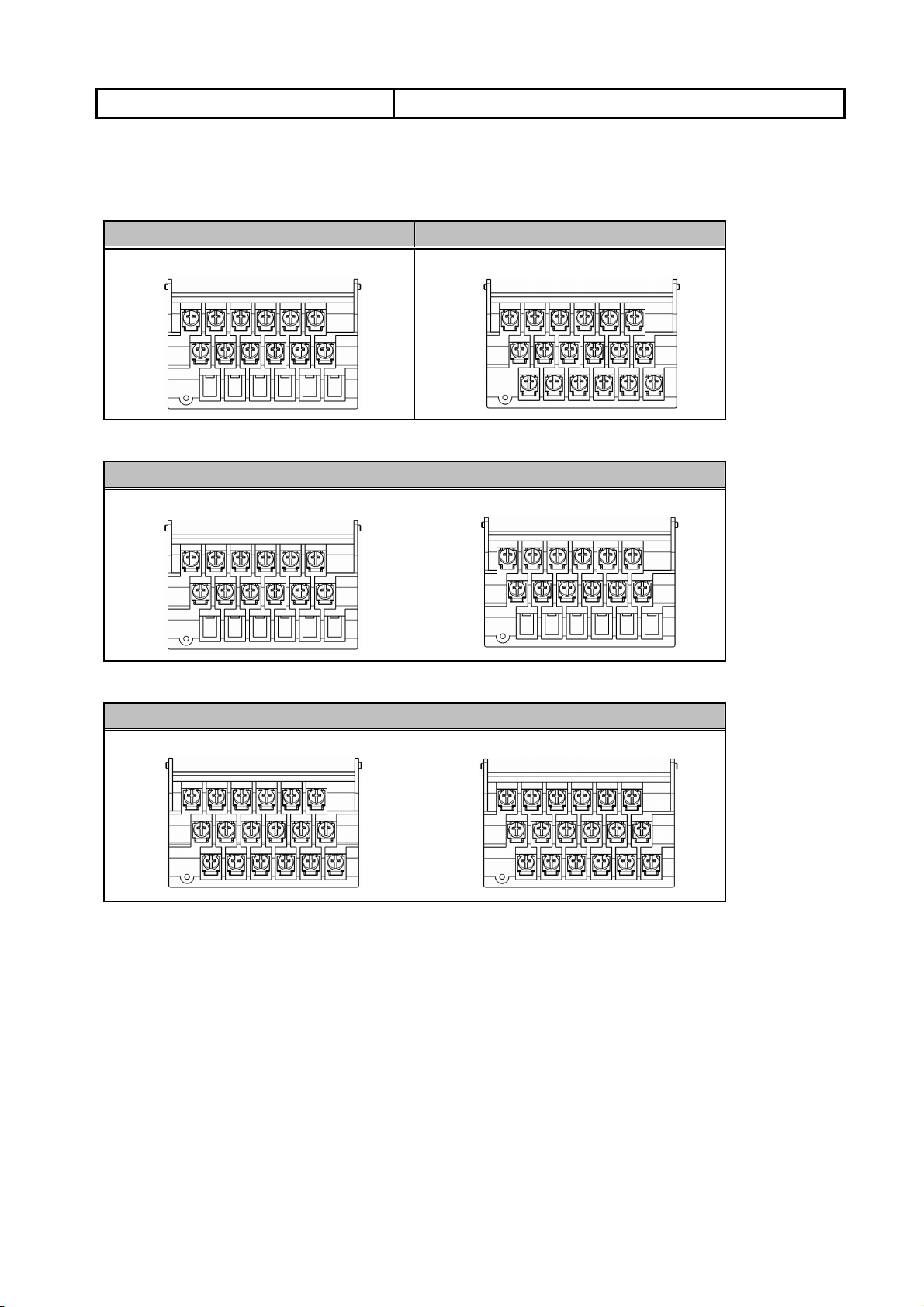
4.4 Measuring Input Terminals
(5) Measuring Input Terminals Arrangement
[Dot-printing type]
1. Dot-printing type, 6 locations
DC voltage (current) and thermocouple (TC) input Resistance thermometer (RTD) input
Channel
1 2 3 4 5 6
(+)
(-)
Channel
1 2 3 4 5 6
(A)
(B)
(b)
2. Dot-printing type, 12 locations, DC voltage (curren t) and thermocouple (TC) input
DC voltage (current) and thermocouple (TC) input
Channel
(+)
(-)
1 2 3 4 5 6
Channel
7 8 9 10 11 12
(+)
(-)
3. Dot-printing type, 12 locations, Resistance thermometer (RTD) input
Resistance thermometer (RTD) input
Channel
1 2 3 4 5 6
Channel
7 8 9 10 11 12
(A)
(B)
(b)
(A)
(B)
(b)
-24-
Page 28
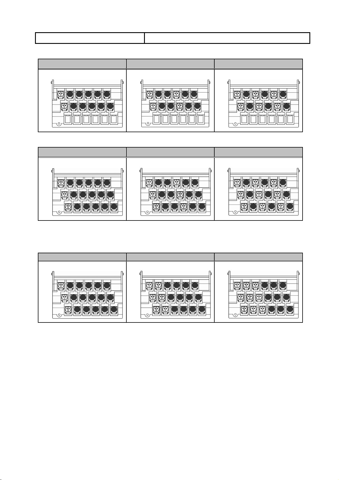
4. CONNECTIONS
4. Dot-printing type, 1/2/3 locations, DC voltage (current) and thermocouple (TC) input
1 location 2 locations 3 locations
Channel
1
4.4 Measuring Input Terminals
Channel
1 2
Channel
1 2 3
(+)
(-)
(+)
(-)
(+)
(-)
5. Dot-printing type, 1/2/3 locations, Resistance thermometer (RTD) input
1 location 2 locations 3 locations
Channel
Channel
1
Channel
1
(A)
(B)
(b)
1 pen 2 pen 3 pen
Channel
(A)
(B)
(b)
[Pen type]
1. Pen type input
1 2
1 2
Channel
1 2 3
(A)
(B)
(b)
Channel
1 2 3
(A)
(B)
(b)
(A)
(B)
(b)
(A)
(B)
(b)
* DC voltage (current) of pen type input and (b) terminal of thermocouple (TC) input channel are embedded with push rivets.
-25-
Page 29
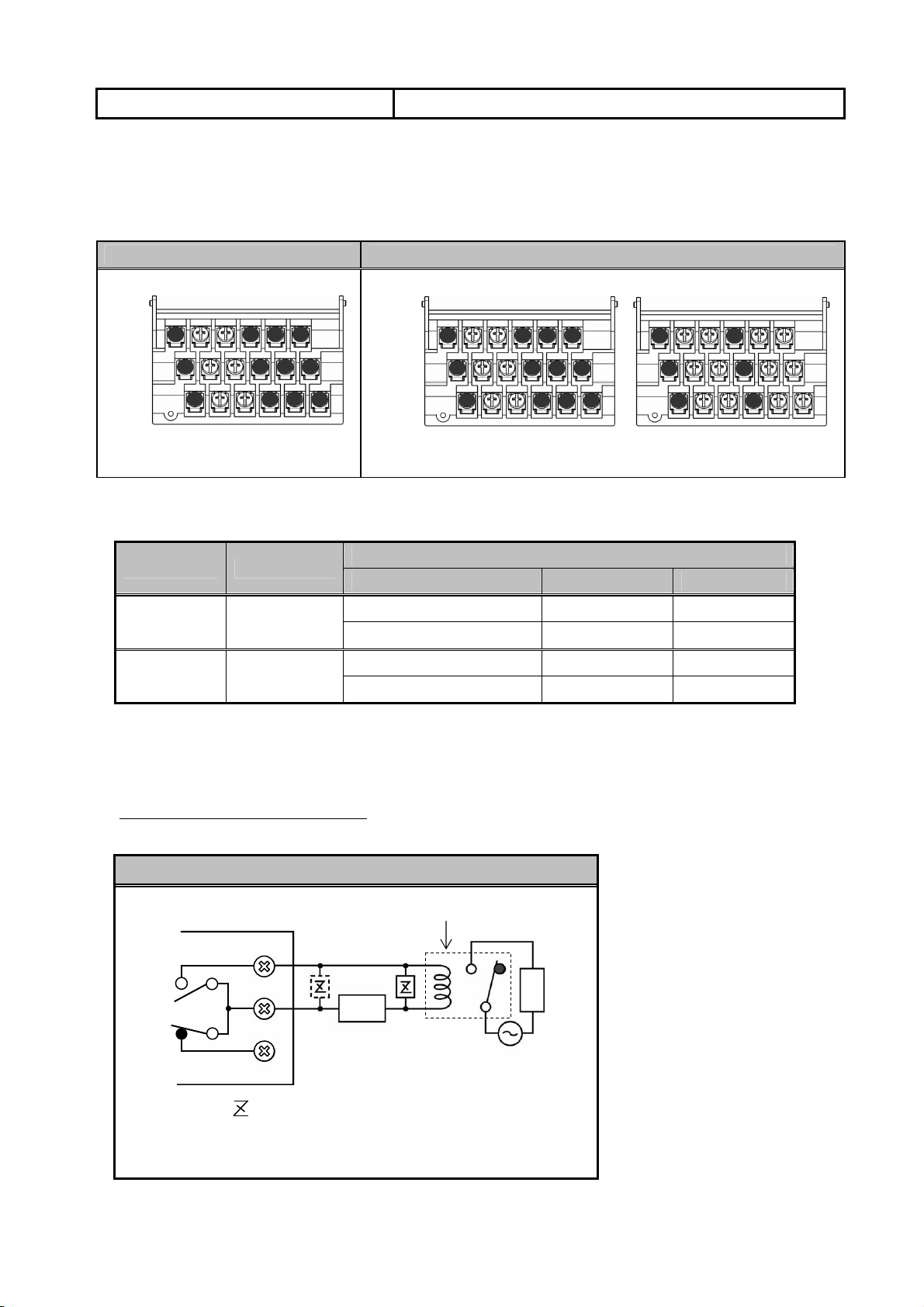
4. CONNECTIONS
L
Alarm output comes with only when alarm output (optional) is specified. The alarm output element is by a Form 1a1b contact
mechanical relay output.
4.5 Alarm Output Terminals (Optional)
(1) Alarm Output Terminals
Dot-printing type 3 pen type
H
H L
H L H L
N.O
COM
N.C
Common output
N.O
COM
N.C
1st pen
output
2nd pen
output
(2) Alarm Output
Alarm type Alarm mode
Output terminal OFF ON
N.O to COM terminals Open Short
“H” alarm Upper limit alarm
N.C to COM terminals Short Open
N.O to COM terminals Open Short
“L” alarm Lower limit alarm
N.C to COM terminals Short Open
Alarm output behavior
(3) Connections
Make sure to turn off the power source and a buffer relay before connections for preventing an electric shock.
1. Connect the cables to a load via a buffer relay.
2. Connect the cables with the crimp style terminal covered by an insulation sleeve to the alarm output terminals.
Connection example for Form 1a1b contact mechanical relay output
The instrument
N.O
COM
N.C
b
Power
supply
*
: Contact protective element (It is recommended to mount it
at the ‘a’ side.)
* N.C terminals have the reverse phase output to N.O terminals;
therefore, they are opened on alarm occurrence.
Buffer relay
a
Load
3rd pen
output
-26-
Page 30

4. CONNECTIONS
2
Connect the load which is equal or less than the specification ( ) to the alarm output terminals.
After connections, the power for the buffer relay is applied to the alarm output terminals and an electric shock occurs if you touch these
terminals. Make sure to close and mount the terminal cover with a screw after the connection.
Take Safety Measures
The alarm outputs of this product may become defective due to wrong operation, failures, abnormal inputs, or others. Take safety
measures separately before use if required.
-marking on Alarm Output Terminals
4.5 Alarm Output Terminals
(4) Cautions on Connection
Remarks and references for connections are as follows.
Remarks1
Power supply Resistive load Inductive load
Remarks2
250VAC
100VAC
* Minimum application load: 5 VDC, 10 mA (Reference
value)
Reference value of switchable lower limit. It may depend
on use conditions, environment conditions, and others;
therefore, check it under actual use conditions.
• Mount a contact protective element matching to the buffer
relay.
• It is effective to mount the element at the coil side of the
buffer relay for preventing a wrong operation due to a light
load (refer to (3) Connections ‘a’ in the figure in
“Connection example for Form 1a1b contact mechanical
relay output”).
Caution on Contact Behavior Timing
The alarm output of this product is by a Form 1a1b contact.
With the 1a1b contact output type, ‘a’ contact side and ‘b’
contact side may turn ON simultaneously on operation and
return.
Confirm operational conditions or others of load side fully
before use.
Contact Ratings of Alarm Output Relay
30VDC 2.0A 1.0A
Mounting of Contact Protective Element Z
2.0A 1.0A
Reference1
• Coil rating: Equal to or less than contact ratings of output
terminals
• Contact ratings: Twice the load current or more
A relay with a built-in element for coil surge absorption is
recommended.
Mount an additional buffer relay if a buffer relay satisfying the
load rating is not available.
Reference
Mount a contact protective element if a buffer relay with a
built-in element for surge absorption is not available.
The element is generally composed of C (Capacitor) and R
(Register).
<Reference values for C and R>
C: 0.01 μF (Rating: About 1 kV)
R: 100 to 150Ω (Rating: About 1 W)
Selection of Buffer Relay
Selection of Contact Protective Element
-27-
Page 31

5. LOADING
5.1 Inkpad Loading (For dot-printing type)
[Dot-printing type]
(1) Preparation
1) Preparation of Inkpad
Take out the inkpad from the accessory box.
Inkpads are colored in advance by ink listed in the table below.
Number of
input points
1 point Red
2 points (1) Red (2) Black
3 points (1) Red (2) Black (3) Sky blue
6 points
12 points
Type and Recording Color
Recording channel number and recording
color
(1) Red (2) Black (3) Sky blue (4) Green (5)
Brown (6) Purple
(1) Red (2) Black (3) Sky blue (4) Green (5)
Brown (6) Purple (7) Orange (8) Gray (9) Blue
(10) Brownish green (11) Scarlet (12) Pansy
For Inkpad Loading
Make sure to pull out the inner unit first when loading or replacing
the inkpad.
Do not load or replace the inkpad by just taking out the scale plate
without pulling out the inner unit. Scale plate is placed at adjusted
position and it may cause indication error. Also, depending on the
placement status, not only it may operate normally but also it may
cause failures.
(2) Inkpad Loading
Attached Inkpad
• Appropriate quantities of ink are filled in advance. Avoid filling
ink in that state. Otherwise the inkpad with too much ink may
have ink drops and others which cause failures.
• Although the period depends on use conditions, the inkpad
can be used for about 2 months with standard specifications and
under standard operational conditions.
Attachment/removal of Inkpad
When attaching or removing the inkpad for loading/replacement
and ink filling, make sure to turn the power off or to be in the
state of RECORD OFF.
Otherwise the indication mechanism operates during inkpad
being attached/removed and unexpected force is applied to the
mechanical parts then the instrument may be damaged.
Replacing the inkpad at the state of RECORD OFF, do not
move indication mechanism manually. It may cause failures.
1) Pulling out the Inner Unit
Pressing the both of levers (Inner unit lock levers) of the right
and left under the rack inward (to the direction of the arrows in
the figure below), hold the right side of the chart cassette (the
part directed by the hand in the figure below) and pull it out.
Pulling out Inner Unit
Pulling out the inner unit fast may damage the inner unit and
the instrument.
When the inner unit is pulled out quietly about 6 cm long, it
stops with the middle stopper. Avoid pulling it out further.
Otherwise it may be damaged.
2) Inserting Inkpad
In the state of the inner unit being pulled out to the middle
stopper, insert the inkpad to the pad axis of the dotting
mechanism.
3) Loading Inkpad
In the state of the inkpad inserted, turn the inkpad with fingers
slowly. When the pin part of the inkpad meets the pad chase
of the dotting mechanism, the inkpad falls and gets loaded.
In the state of the inkpad being loaded normally, the inkpad
does not turn. When it can be turned by a finger easily, it is not
loaded normally. In this case, check the state of the inkpad
falling down turning it slowly.
-28-
Page 32

5. LOADING
e
part
5.1 Inkpad Loading (For dot-printing type)
• Before inkpad loaded
Inkpad
Pin
Dotting mechanism pad
axis
Pad chas
• After inkpad loaded
Dotting mechanism
4) Placing Back the Inner Unit
Press the both sides of the chart cassette until the both levers of
the right and left under the rack are opened outward making a
sound of “click”.
The levers are to secure the inner unit; therefore press them all
the way to lock the unit.
Handling of Pointer
・
Avoid touching the pointer. If force is added, the pointer may be
damaged.
Filling up Ink
• Filling up Ink
When the recording color of points becomes light, add 1 or
2 drops of the attached supplementary ink to the pad
(cotton of the inkpad to apply ink).
At this time, avoid pressing the top of the supplementary ink
to the pad, otherwise the pad is damaged and the ink
cannot be attached easily on recording. In addition, the filled
amount of ink cannot be seen, so overfilling of ink may
happen.
On filling the ink, make sure not to mix up the colors of the
inkpad and the supplementary ink. Pay attention especially
to blue/purple and red/scarlet which are easy to be mixed
up.
Check carefully the number (recording channel number) of
the supplementary ink and the number of the inkpad
recording color.
In addition, the type of supplementary ink depends on the
number of input points. Refer to “Reference: Type and
Recording Color”, (1) Preparation, mentioned early and (3)
Ink Filling Color of Inkpad mentioned later.
• Duration of Use
When ink is filled, the duration of use is half or less
compared with the one when the ink was filled initially (The
duration varies depending on the ink colors.).
• It is Important Not to Add Ink Too Much
When ink is added, note not to add it too much once (1 or 2
drops are enough). Make sure to drop it. Excess ink
generates drops and attachment of ink, and then causes
failures of mechanical parts.
• Life of Inkpad
When ink filling is repeated, ink absorption of the inkpad is
degraded.
If the inkpad is used continuously in that state, recording
quality is degraded, drops and attachment of ink are
generated, and then failures of mechanical parts occur.
Replace an inkpad with new one when ink is filled four or
five times.
The consumption level of inkpads depends on use
conditions. Early replacement is recommended when
recording state gets worse and ink absorption is degraded
on ink filling.
-29-
Page 33

5. LOADING
k
k
k
2
2
2
k
k
2
2
3
3
k
2
5
6
4
3
k
4
3 2 9
2
0
6
7
8
5
(3) Ink Filling Color of Inkpad
[1 point]
1
Red
Red
1
[2 points]
Blac
Red
1
[6 points]
Blac
Sky
blue
*Diagram which can be seen from the side of inkpad
supplementary ink filling.
1
Red
Red
Red
1
Red
Blac
1
Red
Green
Red
1
Blac
Red
1
Purple
Brown
Pin
1
Without a pad
(cotton)
1
With a pad (cotton)
[3 points]
Blac
Sky
blue
[12 points]
Sky
blue
Green
Brown
Red
Red
1
Red
Blac
Purple
Orange
5.1 Inkpad Loading (For dot-printing type)
1
Sky
blue
Blac
1
1
Pansy
11
Scarlet
Brownish
1
Green
Blue
Gray
-30-
Page 34

5. LOADING
5.2 Cartridge Pen Loading (For pen type)
[Pen type]
(1) Preparation
1. Preparation of Cartridge Pen
Take out the cartridge pen from the accessory box.
Inks are colored in advance by ink listed in the table below.
Type
1 pen Red
2 pen (1) Red (2) Green
3 pen (1) Red (2) Green (3) Blue
Type and Recording Color
Recording channel number and recording
color
(2) Scale Plate and Pointer
Positions of scale plate and pointer (index) differ by each type.
[1 pen specification]
[2 pen specification]
1st pen pointer
[3 pen specification]
1st pen scale plate
1st pen index
1st pen pointer
2nd pen scale plate
2nd pen pointer
2nd pen scale plate
1st pen scale plate
2nd pen pointer
3rd pen scale plate
3rd pen pointer
1st pen scale plate
(3) Cartridge Pen Loading
1) Pen Replacement Mode
Pen replacement mode moves cartridge pen to the position
where is easy to load/replace the cartridge pen.
If each pen is at the position of 20 to 80% of recording range,
this operation is unnecessary. If the position of the each pen is
overlapped, remove from the 3rd pen and load from the 1st
pen.
Attachment/removal of Cartridge Pen
When loading or replacing the cartridge pen, make sure to turn
the power off, be in the state of RECORD OFF (all pens are
INDICATE OFF) or perform under the pen replacement mode.
Otherwise the dotting mechanism operates during cartridge pen
replacement and unexpected force is applied to the mechanical
parts then the instrument may be damaged.
1. Bring the cartridge pen DOWN by pulling down the pen lift lever
down located at right side of the inner unit.(refer to (4) Pen Lift
Lever operation mentioned later)
2. Turn the power ON. (refer to 6.1 Turning Power On/Off, 6.2
Operation/Setting Change)
3. While pressing down “◄”
keys simultaneously).
* Perform key operation while front cover is open.
4. Release “◄”
5. “RUN lamp” is off and pointer of the 1st pen, 2nd pen and 3rd
pen move to the position approx. 25%, 50% and 75% of the
scale plate (pen replacement mode).
key and “ENTRY” key.
key, press “ENTRY” key (Press two
Load/replace the cartridge pen at this state.
-31-
Page 35

5. LOADING
e
5.2 Cartridge Pen Loading (For pen type)
Note) If the pen pointer do not move to the specified position,
“ENTRY ” key may not be pressed while pressing down the
key (in this case, it may be in the Chart Speed Change
“◄”
mode, refer to 6.6 Chart Speed Change). Operate from
Operation mode again.
2) Lift up of the 1st pen scale plate
Only for the 1st pen scale plate of the 3 pen specification,
structure allows scale plate to move.
For 3 pen specification, when replacing the cartridge pen of the
1st pen, lift the scale plate up and perform cartridge pen loading.
For lifting up the scale plate of the 1st pen, lift up lower part ((the
part directed by the hand in the figure below) of lower limit side
(left side) of the scale plate. The scale plate would be up until
lower part of the scale plate of 2nd plate.
3 pen specification: the scale plate of the 1st pen is lifted up
For moving scale plate
For lifting up the 1st pen scale plate of the 3 pen specification,
make sure to perform operation at the far left side. If the
operation is done by position other than this, scale plate may be
deformed and cause errors and failures.
Also, the scale plate stops at the stopper position. If the scale
plate is lifted up more than stopper position, it may cause failure
and damage.
Do not move blank scale plate (without scale printing) of the 2
pen specification located at the bottom. The scale plate may be
deformed and cause errors and failures.
3) Load /Replacement of the Cartridge Pen
1. Remove the cap of the pen, bring the color line in the front then
insert protruding portion of the right side into the hole of the pen
holder. Turn the cartridge pen clockwise to load to the pen
holder.
At this time, state of lifting the cartridge pen slightly while
protruding portion of the right side of the cartridge pen is inserted
into the hole of the pen holder creates easy performance.
2. To remove the cartridge pen, turn the cartridge pen
counterclockwise with slightly pushing the protruding portion of the
left side of the cartridge pen.
Removing the pen cap
Do not load the cartridge pen while pen cap is on. It may cause
errors and failures.
Pen cap is used when not recording for long time so keep the pen
cap carefully.
Figure of cartridge pen loading
Color lin
Handling of the pen tip
Tip of the cartridge pen is made of nylon fiber. Do not crush the tip
of the pen.
4) Return to the Operation Mode
1. After loading/replacement of the cartridge pen, press “MODE”
key.
2. Finish the pen replacement mode and return to the operation
mode.
Pen holder
Cartridge pen
Pen cap
-32-
Page 36

5. LOADING
5.2 Cartridge Pen Loading (For pen type)
Remarks
Except for the 1st pen of 3 pen specification, it is easy to
perform cartridge pen loading at the pen up state.
Also, pen up state prevent ink stain by the cartridge pen on the
chart paper (refer to (4) Pen Lift Lever Operation mentioned
later).
Handling of Recording Structure
Avoid moving recording structure right/left by force. If moving
recording structure is needed for loading /replacement of the
cartridge pen use the “Pen Replacement Mode Function” (refer
to Pen Replacement Mode mentioned earlier)
Remarks
For new cartridge pen, ink may not come out easily. Before
loading the cartridge pen, write with the cartridge pen manually
on the paper.
Remarks
The cartridge pen is disposable. Ink consumption level varies
by usage. However, it can be used for about 1.5 months under
standard environment. (Continuous recording of about 600 to
1000m)
Handling of Pointer
Do not touch the pointer. Putting the force to the pointer may
cause indication error and damage.
Remarks
Stop operating and not using for long term or using the unit just
for indication and recording is unnecessary, remove the
cartridge pen and put the pen cap on then store to prevent
drying out of the pen tip and prolong the life of the ink.
Cartridge Pen Loading
Before Replacing the Cart ridge Pen
Ink Consumption Level
Not Recording for Long Term
(4) Pen Lift Lever
• Pen lift lever is located at right side of the inner unit. Bringing
the lever down let cartridge pen down status and raise up the
lever let cartridge pen up status (refer to the figure below).
When recording, let the cartridge pen down status. On the
cartridge pen down status, all the tips of the pens are
contacted on the chart paper and confirm that recording is
done normally.
• Raising up the pen lift lever prevent ink staining on the chart
paper on not recording for temporally and such cases. This
can be resulted in saving ink consumption.
Pen lift lever operation
Pen lift lever
Operation on Pen UP status
Indication operation is enabled while cartridge pen is UP status,
however, performance is not guaranteed.
Also, do not perform indication operation for a long time when
pen is UP status.
-33-
Page 37

5. LOADING
e
(1) Chart Cassette Removal
1) Open the Door.
Door
2) Remove the Chart Cassette.
Grasp the handle on the chart cassette and pull it out.
Check the State of Dotter
[For dot-printing type]
Pull out the chart cassette while RECORD switch is off
(recording off) or power is off for the dot-printing type.
If the chart cassette is pulled out in the state of the dotter
down during power off (The state which top of the dotter
touches the chart. This state may happen if the power is
turned off while the dotter operates.), the dotter may be
damaged.
When the dotter is down, turn the power on once, and when
“initial operation of the dotter” ends, turn the power off (Refer
to 6.1 Power On/Off.).
Guid
Handle
5.3 Chart Loading
[For pen type]
Pen lift is automatically operates itself at the time of pulling
out the chart cassette and putting back into the inner unit
Pen lift lever operation is unnecessary, however, there might
be a possibility that ink stain of the cartridge pen left on the
chart. Let the cartridge pen UP status by the pen lift lever
then load the chart prevent leaving ink stain on the chart.
(2) Chart Paper Setting
1) Open the Chart Paper Holder.
Open the front chart holding axis in the front side and the rear
stripper plate in the rear side.
Front chart holder axis
2) Prepare a Chart Paper.
To prevent double feeding, disentangle the both ends of paper
well.
Pen Lift Lever Operation
Rear stripper plate
-34-
Page 38

5. LOADING
3) Put the Chart Paper in the Container.
Sprocket holes on the right and left of the chart paper are
different. Insert the chart paper with directing ellipse holes on the
right (front side in the figure below) when seen from the front
and the side with the written instructions up.
Circular hole
Drum
Chart paper container
5.3 Chart Loading
Side with written
instructions
Ellipse hole
(3) Chart Paper Loading
1. Pull out the chart paper for about 20 cm and close the rear chart
paper holder.
Note: When the rear chart paper holder is closed, adjust the
position of the chart paper for the held chart paper to be flat. If
the rear chart paper holder is closed with the position for
swelling chart paper, it is closed with bent chart paper, chart
feed failure occurs.
2. Fit the sprocket holes at the right and left of the chart paper to
the sprockets at both ends of the drum.
3. Feed the chart paper and put 2 to 3 folds into the chart paper
tray.
4. Close the front chart paper holder axis applying mild pressure to
the chart paper from the front. Make sure that sprockets of the
both ends of the drum fit over sprocket holes.
Sprocket
(1)
(4)
Chart paper tray
“凸” mark and “凹” mark are printed on the mountain part
and valley part of the both ends of folds of the chart paper
respectively.
When the paper is put into the chart paper tray, make sure not
to put the paper with reversed folds. Reversed folds may
cause folding failure.
凸
mark
(Mountain part of
Chart No.
Time scale
凹
mark
(Valley part of fold)
Folds of Chart Paper
Fold
fold)
Chart paper
(4) Check
Turn the chart feed gear forward (downward) to make sure that the
chart paper feeds properly.
Turn the gear forward (downward). Otherwise, a chart feeding
failure may occur. The chart paper cannot be rewound on the
chart cassette installed into the inner unit.
In the chart feed mechanism, the chart paper is sent with the
sprocket in the chart feed gear part, and the front chart paper
holder axis at the bottom of the chart cassette pulls the paper
lightly to prevent loosening of the chart paper. Some loosening
of the chart paper is corrected during feeding.
Chart feed gear
Turning the Chart Feed Gear
Prevention of Loosening of Chart Paper
-35-
Page 39

5. LOADING
5.3 Chart Loading
(5) Installing the Chart Cassette into the Inner Unit
Guide rails are located at the right and left of the inner unit.
Align the chart cassette to the guide rails and push it into the inner
unit until it clicks (The both inner unit lock levers are opened
outward.).
Now the chart paper loading completed.
When the chart cassette is loaded, backlash of the chart feed
mechanism (allowance of mechanism) is generated.
Note that the chart paper is not fed for a period of time until this
backlash is removed.
• Method to minimize the period of no feeding of the chart
paper by the chart cassette loading.
(1) After the chart cassette loading, put back the chart feed
gear lightly until it stops, and then the chart feed
mechanism backlash can be minimized.
(2) With the front FEED key operation, operate the FEED key
until the chart paper is fed, and then the time of no chart
feeding is almost none.
Guide
When Chart Cassette is Loaded
(6) Chart Feed Check after Chart Loading
1. Turn the power on.
2. Press FEED key to check that the chart paper is sent smoothly.
When the FEED key is pressed continuously, the chart paper is
fed slowly for about 2 seconds, and when the key is pressed
further, the chart paper is fed fast (Refer to 6.3 Chart Feeding
Operation, (2) Chart Feeding).
3. If the chart paper is not fed smoothly, reload the chart paper.
The remaining amount of the chart paper is indicated with the
red number at the right side of the chart paper. When the
remaining is few, the red end mark and characters appear at
the right end of the chart paper.
The chart cassette of this product has a flat surface in the front
which allows notes.
The structure of this product allows manual feeding of the chart
paper (Refer to 6.3 Chart Feeding Operation); therefore, if force
is added downward (feeding) on notes writing, the chart feed
mechanism moves down and the chart paper feeding may be
displaced.
Even if the chart feed mechanism for manual feeding does not
move, the chart paper may be displaced with the mechanism
backlash.
Pay attention to the chart paper not to be moved on writing.
When the chart paper is moved downward, time axis is
displaced, and the chart paper is not fed for the period
equivalent to the backlash of the chart feed mechanism.
Continuous Printing Days of Chart
Chart speed Printing days
12.5 mm/H About 65 days
25 mm/H About 32 days
50 mm/H About 16 days
Remaining Amount of Chart Paper
Notes on Chart Paper
Note on Notes Writing
-36-
Page 40

6. OPERATION/SETTING
6.1 Turning Power On/Off
(1) Turning Power On/Off
Press the power switch of this instrument to turn the power on/off.
The right side of the power switch lever is for on and the left side of it is for off.
(2) Power Lamp Indication
Right after the power is on, the power lamp is lit in orange, and changed to
green immediately.
It is lit in green while the power is on.
[Example of dot-printing type]
Power lamp
* State of front cover closed
Power Lamp Indication
Power Switch
OFF
ON
(3) Operation after the Power is Turned On
1) Initial Operation
When the power is turned on, the following initial operation is
performed.
[For dot-printing type]
1. Dotting operation is repeated until the channel number of the
dotter becomes CH1 (Initial operation of the dotter.).
2. The pointer moves to the left side (lower limit).
3. 3.6 mm long of the chart paper is fed (Refer to 6.3 Chart
Feeding Operation, (1) Chart Feeding on Power ON,).
4. The instrument move to the operation mode
[For pen type]
1. The pointer moves to the left side.
2. 3.6 mm long of the chart paper is fed (Refer to 6.3 Chart
Feeding Operation, (1) Chart Feeding on Power ON,).
3. The instrument move to the operation mode
2) Initial Operation Lamp Indication and Time
1. Right after the power is on, the power lamp is lit in orange,
and the chart paper lighting is lit in high brightness.
2. Right after that, the power lamp is switched to green, and the
chart paper lighting is switched to the specified brightness.
Simultaneously all of the indication lamps, chart speed
(setting parameter), setting mode and pen selection (for pen
type) are lit.
3. Each of the chart speed (setting parameter), setting mode
and pen selection (for pen type) indication lamps are turned
off after about 2 seconds.
4. Become operation mode/lamp indication.
* 1 to 3 of the initial operation takes several to dozen seconds.
3) After Initial Operation End
After the initial operation ends, this instrument moves to the
operation mode. Indication/recording operation and state of
indication lamp depends on the state of switches when the
power is turned on (Refer to (4) Transition to Operation Mode
mentioned later).
This product is the analog recorder in which input state is
recorded with analog trend, however, digital processing is
performed with a microcomputer within the instrument.
When the power is turned on, it takes about 6 seconds at least
and up to a dozen seconds for initialization operation within the
instrument before indication/recording operation starts.
When output of the instrument is used, it takes more time for
normal output state after the power is turned on compared to
the analog instrument with an analog circuit.
Time Period for Initial Operation
-37-
Page 41

6. OPERATION/SETTING
6.1 Turning Power On/Off
(4) Transition to Operation Mode
The instrument moves to the operation mode after the initial operation is completed. Which mode of the operation modes the unit transit
to depends on the state of switches (Refer to the table below.).
[Dot-printing type]
Dotprinting
type
AUTO CH
State of switch
AUTO CH RECORD
ON ON
OFF ON
Operation mode on power on
• Recording mode
For indication and recording
• One-point indication (Only indication without recording) mode
Chart paper feeding stopped
(1) If this instrument was set to this mode on previous power off, the channel
indicated before the power off is indicated.
(2) If this instrument was set to recording mode on previous power off, Channel 1 is
indicated.
• Recording off
The instrument does not indicate and stands by at the left side (lower limit).
Chart paper feeding stopped
RECORD
- OFF
"-“: State of “On" or “Off”
Note: When “AUTO CH” switch is switched (changed), the alarm lamp blinks for about 1.5 seconds.
When “RECORD" switch is switched to off state, the RUN lamp and chart speed lamp blink.
Setting information and various statuses information of the
instrument is stored in the nonvolatile memory (EEP-ROM)
within the instrument.
When the setting information of the instrument is changed, the
alarm lamp blinks for about 3 seconds. When the status
information of the instrument is changed, the alarm lamp blinks
for about 1.5 seconds.
The conditions for nonvolatile memory information change are
described in each setting/operation item.
Blinking of Alarm Lamp
When the instrument moves from the recording mode or one-point indication mode,
it stops operation at the indication position of recording off. For recording off during
indication operation, the instrument stops operation at the position after indication
moved.
-38-
Page 42

6. OPERATION/SETTING
[Pen type]
Pen
type
Note: When “INDICATE” switch is switched to all off state, the RUN lamp and chart speed lamp blink.
State of switch
INDICATE
All ON
Individually
ON
All OFF
• Recording mode
• Individual pen recording mode
• Recording off
6.1 Turning Power On/Off
1st pen INDICATE
3rd pen INDICATE
Operation mode on power on
For indication and recording of all the pens.
Pen of ON: recording mode
Pen of OFF: the instrument does not indicate/record and stands by at the left side
(standby state)
(If the instrument was set to recording mode on power off, stops at indicated position)
The instrument does not indicate and stands by at the left side.
Chart paper feeding stopped
2nd pen INDICATE
Setting information and various statuses information of the
instrument is stored in the nonvolatile memory (EEP-ROM)
within the instrument.
When the setting information of the instrument is changed, the
alarm lamp blinks for about 3 seconds. When the status
information of the instrument is changed, the alarm lamp blinks
for about 1.5 seconds.
The conditions for nonvolatile memory information change are
described in each setting/operation item.
Blinking of Alarm Lamp
-39-
Page 43

6. OPERATION/SETTING
6.2 Operation/Setting Change
(1) Operation/Setting Section
Open the front cover, and perform the following operations/settings.
[Dot-printing type]
[Pen type]
State of Front Cover Opened
1) List of Setting/Operation Items
Various setting/operation items and starting key operation conditions are listed below. Confirm the details of each explanation page
before actual operation/setting.
Category Setting/operation item
Key operation mode 1 Key operation mode 2
“ALARM” “CAL”: Off “ALARM” “CAL”: Intermittent blink *1
Chart speed change Select by single press of “◄”/”►” X
Alarm setting Single press of “MODE” X
Setting
mode
Operation
mode
Statu s
operation
* “X”: The condition of setting/operation disabled is indicated.
* Simultaneous single press: While the left key is pressed, the right key is pressed once (Simultaneous single press of two keys. Refer to
User indication adjustment
Shift Programming
Pen replacement mode
(pen type)
Chart paper lighting
brightness dimming
Key operation mode
1 → 2
Key operation mode
2 → 1
Pen marker operation X Single press of “◄”/”►”
Simultaneous single press of
“MODE” + “◄”
Simultaneous single press of
“MODE” + “►”
Simultaneous single press of
“◄” + “ENTRY”
Simultaneous single press of
“►” + “ENTRY”
3 sec. press of “ENTRY” X
X Single press of “MODE”
Simultaneous single press of
“◄” + “ENTRY”
Simultaneous single press of
“►” + “ENTRY”
X
X
(2) Key Operation Type mentioned later.).
*1: Intermittent blink: Blink of lighting (about 0.2 sec.) → Off (about 0.8 sec.) repeated.
Avoid simultaneous press of multiple keys other than specified
key operations, simultaneous operation for switches, and
simultaneous operation for a switch and key.
Otherwise, wrong operations or wrong behavior of the
instrument may occur.
Avoid Simultaneous Operations.
-40-
Page 44

6. OPERATION/SETTING
t
6
(2)Key Operation Type
Key operation methods are as follows.
Single press
A:
Simultaneous single press of 2
A:
B:
6.2 Operation/Setting Change
keys
A:
3 sec. press
3 seconds
Simultaneous 3 sec. press of 2
keys
A:
B:
3 seconds
A key is pressed and released
immediately.
:Key operation recognition timing
* Some key operations are recognized when keys are pressed,
and some key operations are recognized when keys are
released.
Method 1
While a key is pressed, another
key is pressed and released
immediately, and then the
pressed key is released.
Method 2
Two keys are pressed and
released immediately
simultaneously.
A key is pressed continuously
for 3 sec. or more. When the
operation is recognized, the
key is released.
When quick key operations are performed continuously, they
may not respond. Wrong operations or setting may occur;
therefore always check the responses of key operations
(switching of display) while operating.
Especially with operations which involve operations of indication
mechanism, check switching of display and completion of
indication mechanism operation for secure key operations.
(3) DIP Switch Function
In the state of front cover opened, there is a DIP switch at the lower left.
When functions assigned actually are used, confirm the description of each
explanation page.
DIP Switch Functions Assignment
No. Function name Explanation
Switch it to ON for user indication
1 CAL
Fixed (For
2
factory)
3 Fixed
4 Fixed
5 Fixed
6 KEY LOCK
adjustment and shift programming.
(* Alarm value setting disabled when
turned ON)
Make sure to switch them to OFF.
It has key lock function to disable various
settings. ON means a state of key locked.
Method 1
While a key is pressed, another
key is pressed continuously for
3 sec. or more. When the
operation is recognized, both
keys are released.
Method 2
Two keys are pressed
continuously for 3 sec. or more
simultaneously. When the
operation is recognized, the
key is released.
Check Responses of Key Operation
OFF
DIP Switch Functions Assignmen
12345
ON
CAL
KEY LOCK
-41-
Page 45

6. OPERATION/SETTING
6.2 Operation/Setting Change
(4) Monitor Function
Monitor functions of each lamp are listed below.
Operation mode Setting mode
Lamp name
RUN On Long blink On/Off Off
MODE
PEN SELECTION (Pen type
only)
CHART SPEED On Long blink Blink: On On
* Blink: On (about 0.5 sec.) → Off (about 0.5 sec.) repeated.
* Long blink: On (about 0.8 sec.) → Off (about 0.8 sec.) repeated.
ALARM
CAL
Recording mode
One-point
indication
Off Blink: On On
Off Blink: On On
Recording off Setting candidate Setting/Selection
(5) Operating Condition
Setting transition conditions, operation states, restriction conditions, operations on transition, and others during operation mode are listed
below.
[Dot-printing type]
Operation mode
Setting/operation mode
( : key lock function target )
: Chart speed change
: Alarm setting
: User indication adjustment /
Shift Programming
Chart paper lighting brightness
dimming
Transition availability: O means “yes”, and X means “no”.
*1: The setting error is displayed (RUN/ALARM/CAL lamp: Blink (On about 0.2 sec.→ Off about 0.2 sec.) is repeated for 1.5 sec.).
Even when the setting change is performed in the key lock state, the same setting errors are displayed (Refer to 6.9 Use-specific
Operation/Setting Function, (2) Key Lock Function,).
*2: Position correction operation of indication (recording) mechanism is executed first on operation mode return.
Note 1: Input update is stopped during recording off.
Recording
mode
O
X
(*1)
X
(*1)
O O O Continuation Continuation
One-point
indication
O O Continuation
O
O
Recording
off
(Note 1)
X
(*1)
X
(*1)
Input update Return operation
Continuation/change
switching
Sto p
Sto p
Indication position correction
(*2)
Indication position correction
(*2)
-42-
Page 46

6. OPERATION/SETTING
[Pen type]
Setting/operation mode
( : key lock function target )
: Chart speed change O O O Continuation
: Alarm setting O O O Sto p Continuation recovery
: User indication adjustment
Shift Programming
Pen selection O O O Stop (Note 2) Continuation recovery
Chart paper lighting brightness
dimming
Transition availability: O means “yes”, and X means “no”.
Note 2: Input update is continued during recording off.
Note 3: Only input update is continued.
Recording
mode
6.2 Operation/Setting Change
Operation mode
One-point
indication
O O O Sto p Continuation recovery
O O O Continuation Continuation
Recording
off
(Note 1)
Input update Return operation
Continuation/change
switching
-43-
Page 47

6. OPERATION/SETTING
6.3 Chart Feed Operation
(1) Chart Paper Feeding on Power On
After the power is turned on, a certain amount (3.6 mm) of the chart
paper is fed for eliminating the chart feed mechanism backlash
(allowance of mechanism) before starting recording (chart feeding).
Actual amount of the paper to be fed depends on the state of the
mechanism backlash.
After the mechanism backlash is eliminated once, when the power is
turned on again, 3.6 mm long of the paper is fed.
(2) Chart Paper Feeding
1) Feeding with Key Operation (Manual Operation)
Chart paper can be fed with manual operation with FEED key
(Refer to 3.2 Display Operation Part.).
Key operation Chart paper feeding
Single press
(One time press)
About 0.3 sec. to 2 sec. or
less
(Continuous press)
About 2 sec. or more
(Continuous press)
*Operation is available at recording off (RECORD switch
off/INDICATE switch all off).
0.1 mm long feeding
Feeding with speed of 100 mm/min.
* Continues while the key is being
pressed
Feeding with speed of 10 mm/sec.
* Continues while the key is being
pressed
(3) Fitting Chart Paper Time Line
• Operate FEED key or feed the chart paper manually to fit the
dotter recording position/cartridge pen recording position and the
time line of the chart paper.
For time line fitting, put back the chart feed gear lightly until it
stops after the manual feeding to minimize the chart feed
mechanism backlash. Adjust the time line in this state.
• Fit the time line after the power is turned on.
Even if the time line on the chart paper is adjusted to the dotter
recording position/cartridge pen recording position, there will be a
gap (3.6 mm) on the time line of the chart paper caused by the
chart feeding function when turning power on again after a
momentary power interruption, etc.,
Time Line fitting with Manual Feeding
When Momentary Power Interruption Occurred
2) Manual Feeding
The chart paper can be fed by turning the chart feed gear forward
(downward).
When the chart paper is fed manually, backlash of the chart
feed mechanism (allowance of mechanism) is generated.
Note that the chart paper is not fed for a specified period
depending on the state of the manual operation.
• Method to minimize the period of no feeding of the chart
paper by the manual feeding
1. After the manual feeding, put back the chart feed gear
lightly until it stops, and then the chart feed mechanism
backlash can be minimized.
2. With the front FEED key operation, operate the FEED key
until the chart paper is fed, and then the time of no chart
feeding is almost none.
Numbers of 1 to 24 are printed on the left side of the chart
paper at intervals of 25mm. This is a time scale for running
with the chart speed of 25mm/H.
For manual feeding, due to a certain constructional limit of
resolution, the time line may not be adjusted accurately.
Only Chart Paper Feeding Operation
Only feeding operation can be performed manually with the
chart feeding mechanism.
The chart feed mechanism backlash can be put back lightly;
however, further backward operation cannot be performed.
Otherwise it may be damaged.
For the pen type, there is a gap on the time line of the
recording position of each pens (7.1 refer to Recording
Operation (Pen type)). For the adjustment of the time line,
adjust cartridge pen recording position of the standard pen and
time line.
For Manual Feeding
Time Scale (1 to 24)
Accuracy of Time Line Adjustment
Time Line Adjustment for Pen Type
-44-
Page 48

6. OPERATION/SETTING
6.4 Recording Operation (AUTO CH/ INDICATE Switch)
(1) AUTO CH/INDICATE Switch (Refer to 3.2 Display
Operation Part.)
[Dot-printing type] AUTO CH Switch
1) When AUTO CH Switch is Up Position (ON State)
Channels are switched with 6-second interval (Option: 3-second
interval for dotting interval of 3 seconds), and
indication/recording is performed (Recording mode).
Update input linked to channel switching interval.
2) When AUTO CH Switch is Down Position (OFF State)
No recording is performed, and the input of the channel
indicated by the dotter is taken in with 1-second interval and only
indication is performed (One-point indication mode).
The procedure for the one-point indication mode is as follows.
1. When the channel indicated by the dotter becomes the one
you want to indicate, place the AUTO CH switch in the down
position.
2. The alarm lamp blinks for about 1.5 sec., and chart feeding
and dotting operation stop. Only pointer moves in
accordance with the input value.
3. To restart recording, place the AUTO CH switch in the up
position.
On one-point indicate mode, update input data by every one
second. Start moving indication by input data and when stop
moving (indication position), start moving by next data of input
update interval. The data inputted during indication is moving. It is
not to be a target of indication.
When AUTO CH switch is switched (changed), the alarm lamp
blinks for about 1.5 seconds. The indication channel information
during the one-point indication mode is written to the internal
nonvolatile memory (EEP-ROM).
During the recording mode the indication position is corrected
for every 12 points; however, during the one-point indication
mode it is not corrected. If the position of the indication
mechanism is displaced by external causes or others, the
displacement continues without change.
For the one-point indication mode usage for a long term, it is
recommended to switch to the recording mode regularly.
Switching of AUTO CH Switch
Notes on One-point Indication Mode Usage
Indication (recording) positions are corrected per 12 points. On
the position correction operation, the indication moves to
around the lower limit position, and temporary standby (stop)
operation is performed.
The position correction operation is performed for every 12
points regardless of the number of input points.
• 12-point instrument: Once for one interval (12 points)
• 6-point instrument: Once for two intervals (6 points x 2 times)
Flow Chart of AUTO CH Switch Operation
Recording mode
Is the channel the one
NO
Place AUTO CH switch in the down position.
YES
Points where instrument operations are needed.
Points where instrument operates automatically.
you want to indicate?
YES
Only indication, without recording
Do you want to
restart recording?
YES
Place AUTO CH switch in the up position.
Recording mode
Do you want to
change the channel?
NO
Recording mode
Indication (Dotting) Position Correction
NO
-45-
Page 49

6. OPERATION/SETTING
e
e
e
[Pen type] INDICATE Switch
1) When INDICATE Switch is Up Position (ON State)
Indication/recording of relevant pen is performed.
2) When INDICATE Switch is Down Position (OFF State)
No indication/recording of relevant pen is performed and
become standby state (indication/recording stop). Relevant pen
stops at the position where it indicated just before turning the
INDICATE switch down (OFF).
When INDICATE switch of all the pen is DOWN Position OFF
state) the instrument become recording OFF state
(indication/recording stop) and chart feeding also stops.
Figure of scale plate/pointer
[Example of three pen specification]
6.4 Recording Operation (AUTO CH/ INDICATE Switch)
3rd pen
scale plat
2nd pen
scale plat
1st pen
scale plat
-46-
Page 50

6. OPERATION/SETTING
e
6.5 Pen Marker (Only for 2/3 pen type)
(1) Pen Marker
This is for 2/3 pen type. Pen not using for recording of input update
can be used for marker line recording.
At the event, press left/right key at an arbitrary timing moves
recording position and perform marker line recording. Moving
resolution of one press of left/right key is 2.5% and continuous
operation is available. Movable range is 0 to 100% of recording.
1) For 2 Pen Type
When 2nd pen is at the standby state (INDICATE OFF), 2nd pen
can be used as a pen marker.
1. Turn 2nd pen switch down (OFF State).
2. Press “ENTRY” key until next reaction.
3. Press “ENTRY” key for more than 3 seconds light “ALARM”
and “CAL” lamp intermittently (key operation mode 2) then
release the “ENTRY” key.
4. Press either left/right key once moves indication/recording of
2nd pen to the direction of the key pressed for 2.5%
(4.5mm). Every press of left/right key moves
indication/recording 2.5%.
• At the power on, it is on the “Key Operation State 1”. Pen
marker operation is disabled. “Key Operation State 2” is mode
for pen marker operation. At this state, setting change or
adjustment is not available (pen replacement mode and chart
paper lighting brightness dimming are available). On “Key
Operation State 2” pressing the “MODE” key returns to the “Key
Operation State 1” (“ALARM” and “CAL” lamp turn off).
First press of the left/right key moves indication/recording to the
recording position of 2.5% resolution. Therefore only for the first
movement, moving amount is less than 2.5%.
• Returning 2nd pen INDICATE switch up (On State) changes
2nd pen to the recording mode.
When recording is OFF state (INDICATE switch of the all pen is
OFF), pen marker function is invalid.
2) For 3 Pen Type
When 3rd pen is at the standby state (INDICATE OFF), 3rd pen
can be used as a pen marker. Function is same as 2nd pen of 2
pen type.
• Returning 3rd pen INDICATE switch up (On State) changes 3rd
pen to the recording mode.
When recording is OFF state (INDICATE switch of the all pen is
OFF), pen marker function is invalid.
Operation of the Pen Marker
Make sure to operate pen marker indication/recording position
by left/right key. Do not move pen mechanism directory. The
mechanism may be damaged.
Pen marker position is not hold at power OFF (including short
power interruption). Power ON after these conditions, pen
marker stops at the lower limit position (refer to 7.3 Behavior on
Abnormal Input, under range).
Pen marker position is enabled only when pen marker function
is in the use. Once pen marker function is disabled (including
power OFF and short power interruption), position information is
also disabled. Set again if necessary.
First Moving Amount
Operation After the Power Failur
About Pen Marker Position Hold
-47-
Page 51

6. OPERATION/SETTING
6.6 Chart Speed Change
(1) Chart Speed Switching
1) Chart Speed Indication
Upon transition to the operation mode, the lamp corresponding
to the chart paper speed lights. Simultaneously the lamp
corresponding to the unit indication lights. The right figure
shows setting of 50 mm/H.
The chart speed indication can be seen while the front cover
closed; however, other setting keys and lamp indication can be
seen or operated only when the front cover is opened.
2) Chart Speed Change
Set or change the chart speed in the state of the front cover
opened.
• Chart Speed Change Procedure
z When Chart Speed is 50 mm/H
State of front cover opened
Chart Speed Indication Section
Note: The indication lamps show the state right before key
operation. The dark color shows lighting and faint color
shows blink state.
Operation mode
Chart speed indication lamp blinks.
Move the blink position to the chart speed indication lamp
to be changed (Unit indication lamp is linked to the
switching.).
Alarm lamp has short blinks (for about 3 seconds).
Changed chart speed indication lamp lights.
Change ends: Operation mode
* For the lamp blink transfer pattern, refer to
(2) Chart Speed Numerical Sequence mentioned later.
Chart Speed Set
◄or ►
◄or ►
ENTRY
Chart speed is set when ENTRY key is pressed (The chart
speed is written within the instrument.).
When the setting value is set (changed), the alarm lamp blinks
for about 3 seconds.
* The figure above shows the example of change of 25mm/H to
75mm/H.
-48-
Page 52

6. OPERATION/SETTING
t
t
* When MODE key is pressed during setting, the setting
mode is finished.
* When nothing is performed during setting, the setting
mode is finished after about 10 seconds.
* Even while the chart speed change is being set, the
indication/recording operation is continued.
Chart speed is set to the second speed: 25 mm/H before
shipping.
Key Operation
Chart Speed at Factory Setting
6.6 Chart Speed Change
(2) Chart Speed Numerical Sequence
Selectable Chart Speed Numerical Sequence
Chart speed Chart speed numerical sequence
1
2
6-speed
(standard)
5-speed
hour/min.
switching
(optional)
* The above are basic chart speeds. If you desire a chart speed
other than the numerical sequences above, contact your nearest
CHINO’s sales agent.
3rd speed: 50mm/H
4th speed: 75mm/H
5
6th speed: 150mm/H
1
2
3rd speed: 50mm/H, 50mm/M
4th speed: 100mm/H, 100mm/M
5
s
speed: 12.5mm/H
nd
speed: 25mm/H
th
speed: 100mm/H
s
speed: 12.5mm/H, 12.5 mm/M
nd
speed: 25mm/H, 25mm/M
th
speed: 200mm/H, 200mm/M
When the chart speed is changed, switch chart speed numerical sequences with either one of left/right
key to select (switch chart speed lamps.). For the right key, numerical sequences are switched in the
order below. For the left key, they are switched in the adverse order.
For the 5-speed hour/min. switching (optional), the unit is switched with link to the numerical sequences
switching (The unit indication lamp is switched.).
● 6-speed (standard)
12.5 mm/H
25 mm/H
50 mm/H
75 mm/H
100 mm/H
150 mm/H
Chart Speed Numerical Sequence Switching
● 5-speed hour/min. switching (optional)
12.5 mm/H
25 mm/H
50 mm/H
100 mm/H
200 mm/H
12.5 mm/M
25 mm/M
50 mm/M
100 mm/M
200 mm/M
-49-
Page 53

6. OPERATION/SETTING
e
e
6.7 Alarm Specifications
(1) Alarm Type
The following are the types of alarm and examples of
activation/reset of alarm.
Alarm type Alarm level
Upper
limit/lower limit
• Upper limit/lower limit alarm
1. “L” alarm (lower limit alarm): Alarms are activated on alarm value ≧ measured value.
2. “H” alarm (upper limit alarm): Alarms are activated on alarm value ≦ measured value.
Measured value
“H” alarm setting valu
“L” alarm (lower
limit alarm)
“H” alarm (upper
limit alarm)
Example of Alarm Activation/Reset
Upper Limit/Lower Limit Alarm
* Combination of the alarm is described as “Alarm type”. Alarm
type of this product is upper limit/lower limit alarm.
Each alarm status (“L”alarm and “H” alarm) is described as
“Alarm level”.
Normal range
“L” alarm setting valu
Time
(2) Alarm Deadband
Alarms are activated when input values become
alarm setting values (lower limit value or less/
upper limit value or more), and they are reset
Lower limit alarm
Deadband
when input values returns to the values just before
the alarm setting values.
The difference is called “Alarm deadband” which is
indicated with % of scale width (measuring range).
ON
(Reset)
It is set to 0.4% for this product.
(Activation)
MIN MAX
Alarm setting value
Measured value
On “L” alarm reset
Deadband
Alarm Deadband
“H” alarm setting
value
“L” alarm setting
value
0.4%
“L” alarm activation
“H” alarm activation
Alarm Deadband
OFF
Upper limit alarm
Deadband
(Reset)
OFF
MIN MAX
On “H” alarm reset
Alarm setting value
Deadband
0.4%
ON
(Activation)
Normal
range
Time
-50-
Page 54

6. OPERATION/SETTING
A
F
123456
6.8 Alarm Setting
(1) Alarm Setting
1. A value you desire for an alarm to be activated can be set for the
indication value (setting resolution: 0.25 %).
2. The alarm value for an upper limit alarm/lower limit alarm which is
common to all channels for dot-printing type and individual set
by each pen for pen type can be set.
3. Alarm setting and clear (alarm determination release) for upper
limit alarm/lower limit alarm are performed collectively for all
channels for dot-printing type and individual set by each pen for
pen type (Refer to “Alarm Setting Value”, the right.).
4. In any channel become alarm value (lower limit value or
less/upper limit value or more) the alarm is activated, and the
alarm lamp lights. In addition, when the alarm output (optional) is
available, the contact signal of upper limit alarm/lower limit alarm
can be output on alarm activation.
5. The alarm lamp continues to light until all alarms activated are
reset.
(2) Setting Procedure for Alarm Values
Refer to the flow chart mentioned later.
1) Transition to Alarm Value Setting Mode
[Dot-printing type]
Alarm setting can be performed only from the one-point
indication mode.
In the recording mode (RECORD ON) when the dotter is
switched to the channel for alarm setting, place the switch to the
one-point indication mode. Note that if the AUTO CH switch is
placed in the down position right before dotting, dotting is
performed and then the channel is switched.
When a single scale is used, you do not need to check the
channel indicated by the dotter.
2) Setting Procedure for Alarm Values
Check that all DIP switches are off.
(Refer to 6.2 Operation/Setting Change (3) DIP Switch
Function.)
Dot-printing type: RECORD ON, one-point indication mode
Pen type: Operation mode
RUN lamp off
ALARM lamp blinks.
(Alarm lamp off: *1)
*1 Alarm judgment is not performed during alarm value
setting mode. When switch to alarm value setting
mode at alarm activation, alarm lamp is turned off.
OF
ON
MODE
[Pen type]
Alarm setting can be performed from any operation mode.
Specifying input channel can be performed from alarm setting
mode.
• Setting value
[Dot-printing type]
For a single scale, set values are reflected to all channels. For
the double/triple scale (optional), the setting value is reflected
to the channel with the same scale as the channel of the
dotter on transition to the alarm setting mode.
[Pen type]
The setting value is reflected at the every pen input.
• Setting value clear
[Dot-printing type]
For a single scale, alarm values of all channels are cleared.
When the double/triple scale (optional) is used, the alarm
value of the channel with the same scale as the channel of
the dotter on transition to the alarm setting mode is cleared.
[Pen type]
The alarm value is cleared at the every pen input.
For settings with indication mechanism operation, always check
responses of key operations (switching of display) and
completion of indication mechanism operation when performing
key operation unfailingly since wrong operations or setting may
occur.
Note: The indication lamps show the state right before key
operation. The dark color shows lighting and faint color
shows blink state.
For dot-printing type, there is no lamp indication part for pen
selection.
Alarm Setting Value
Check Completion of Mechanism Operation
-51-
Page 55

6. OPERATION/SETTING
A
C
Chart Speed lamp off
ALARM lamp lights
Pen Select lamp (“1”: 1st pen) blinks (*2)
Move the blinking position to the pen select lamp to be set
(changed).
The pen select lamp to be set (changed) lights.
The alarm level select lamp “L” blinks.
B
Move the blinking position to the alarm level select lamp
to be set (changed).
The alarm level select lamp to be set (changed) blinks.
The pointer moves to the current alarm setting value.
(Pen type: except for the selected pen, the pointer moves
to the opposite of indication overshoot position of alarm
level to be set).
Move the pointer to the alarm value to be set (changed).
((While the pointer is being moved, the alarm lamp has
short blinks: * 3)
Mentioned later.
ENTRY
*2 For dot-printing type and 1 pen type, pen selection is
not available and move to next alarm level selection
B (for 1 pen type, 1st pen selection lamp lights).
○
◄or ►
ENTRY
◄or ►
ENTRY
◄or ►
*3 Refer to 3) Setting Method for Alarm Values
6.8 Alarm Setting
-52-
Page 56

6. OPERATION/SETTING
C
Alarm lamp has short blinks (for about 3 seconds).
The alarm level select lamp to be set (changed) blinks.
When the alarm value
setting is finished
ALARM lamp off
Dot-printing type: RUN lamp and chart speed lamp light.
Pen type: Operation mode/lamp indication
Change completed
Dot-printing type: Return to one-point indication
mode
Pen type: Return to operation mode
ENTRY
When another alarm
value is set, go to
○B
MODE
6.8 Alarm Setting
.
* Blink: On (about 0.5 sec.) → Off (about 0.5 sec.) repeated.
* Short blink: On (about 0.2 sec.) → Off (about 0.2 sec.) repeated.
-53-
Page 57

6. OPERATION/SETTING
[Dot-printing type]
“L” level: Transition to lower limit
alarm setting mode
Alarm level select lamp “L” lights.
The pointer moves to the current alarm value
or initial position.
Move the pointer to the scale you desire for the
alarm to be activated by pressing
Press ENTRY key.
Alarm lamp blinks and the alarm setting value is written.
Do you want to set the “H”
YES
level alarm, too?
NO
NO
Place AUTO CH switch in the down position.
◄/► keys.
RUN lamp and chart speed indication lamp light.
6.8 Alarm Setting
Flow Chart of Alarm Setting
Recording mode
Is channel the one you desire to
set indicated by the dotter?
YES
(One-point indication mode)
Press MODE switch.
ALARM lamp blinks.
Press ENTRY key.
ALARM lamp lights.
Alarm level select lamp “L” blinks.
Select the alarm level with ◄/► keys.
Press ENTRY key.
Press MODE switch.
Place AUTO CH switch in the up position.
Recording mode
All DIP Switches: OFF
* When the instrument has a
single scale, you do not need to
check the channel indicated by
the dotter.
Points where operations
of the instrument are
needed
Points where the instrument
operates
“H” level: Transition to upper limit
alarm setting mode
Alarm level select lamp “H” lights.
The pointer moves to the current alarm value
or initial position.
Move the pointer to the scale you desire for the
alarm to be activated by pressing
Press ENTRY key.
Alarm lamp blinks and the alarm setting value is written.
Do you want to set the “L”
level alarm, too?
NO
All DIP Switches: Return to
◄/► keys.
previous state
YES
-54-
Page 58

6. OPERATION/SETTING
[Pen type]
6.8 Alarm Setting
Flow Chart of Alarm Setting
Operation mode
All DIP Switches: OFF
“L” level: Transition to lower limit
alarm setting mode
Press MODE switch.
ALARM lamp blinks
Press ENTRY key.
ALARM lamp lights.
Pen select lamp “1” blinks.
Press ENTRY key.
Selected pen select lamp lights.
Alarm level select lamp “L” blinks.
Select the alarm level with ◄/► key.
Press ENTRY key.
Points where operations
of the instrument are
needed
Points where the instrument
operates
* For 1 pen type, pen select
lamp “1” blinks then move to
next alarm level selection.
“H” level: Transition to upper limit
alarm setting mode
Alarm level select lamp “L” lights.
The pointer moves to the current alarm value or
initial position.
Move the pointer to the scale you desire for the
alarm to be activated by pressing
Press ENTRY key.
Alarm lamp blinks and the alarm setting value is written. Alarm lamp blinks and the alarm setting value is written.
Do you want to set the “H”
YES
level alarm, too?
NO
◄/► keys.
Press MODE switch.
Operation mode/lamp indication
Operation mode
Alarm level select lamp “H” lights.
The pointer moves to the current alarm value or
initial position.
Move the pointer to the scale you desire to be
activated for the alarm by pressing
Press ENTRY key.
Do you want to set the “L”
level alarm, too?
NO
All DIP Switches: Return to
◄/► keys.
previous state
YES
-55-
Page 59

6. OPERATION/SETTING
e
p
When the alarm level is selected, there are “LL” and “HH” levels
indications at the both sides of “L” and “H” under the indication
lamps; however, they cannot be selected on alarm setting.
The “LL” and “HH” levels indications are reserved for handling
of special specifications.
3) Setting Method for Alarm Values
(1) Moving of Pointer
When the alarm level is selected in the alarm setting mode, the
pointer moves to the current alarm value.
If “L” level (lower limit alarm) is selected and an alarm value is
not set, the pointer moves to the under-range position (leftmost).
If “H” level (upper limit alarm) is selected and an alarm value is
not set, the pointer moves to the over-range position (rightmost)
(Refer to “Position of Pointer When Alarm Values Not Set"
below.).
(2) Fixing of Alarm Setting Value
For setting alarm values, move the pointer to the scale you
desire for the alarm to be activated pressing right/left keys. While
the pointer moves, the alarm lamp repeats short blinks. When
ENTRY key is pressed, the alarm lamp blinks, and the alarm
setting value is fixed.
The alarm setting value is fixed when ENTRY key is pressed
(the alarm setting value is written within the instrument).
When the alarm setting value is set (changed), the alarm lamp
blinks for about 3 seconds.
Alarm type Level Position of pointer
Upper limit/lower
limit alarm
Alarm Level Selection
Fixing of Alarm Setting Value
Position of Pointer When Alarm Values Not Set
“L” alarm (lower limit alarm) Under-range
“H” alarm (upper limit alarm) Over-range
6.8 Alarm Setting
The pointer moves 0.2 mm by pressing the right or left key
once (release immediately after pressing).
The moving resolution of the pointer is 0.2 mm, and the
setting resolution of the alarm value is 0.45 mm (0.25 %).
* The moving resolution of the pointer is twice or more
compared to the setting resolution of the alarm setting value.
The pointer moves continuously when the right or left key is
pressed for about 0.3 seconds or more. When the key is
continuously pressed further, the moving speed of the pointer
becomes faster after about 2 seconds. If the key is released,
th
ointer slows down its speed immediately and stops.
* When MODE key is pressed during setting, the setting mode
is finished and the operation mode is placed back.
If the instrument is left during the setting, the setting mode is
*
finished and the operation mode is placed back after about 1
minute. In the case where the alarm value is to be set (the
pointer can be moved), the state is continued.
* Indication/recording operation is interrupted during the setting.
Position that moved to about 0.45% (about 0.8mm)
lower side from the record 0% position
Position that moved to about 0.45% (about 0.8mm)
upper side from the record 100% position
Moving of Pointer by Pressing Right/Left Key
Key Operation
-56-
Page 60

6. OPERATION/SETTING
0
0
6.8 Alarm Setting
(3) Clearing Alarm Setting Value (Alarm Judgment
Release)
Clear the alarm setting values in the alarm setting mode (Refer to
(2) Setting Procedure for Alarm Values mentioned early.).
Clear the alarm setting values of all channels commonly for
dot-printing type and individually for the pen type.
1) Clearing All Alarm Level Setting Values
While the alarm level select lamp (“L” or “H” level) blinks, press
the both right and left keys simultaneously for 3 seconds or
more (Press two keys simultaneously for 3 seconds. Refer to
6.2 Operation/Setting Change (2) Key Operation Type). The
alarm lamp blinks and the alarm setting value is cleared.
* For the dot-printing type, all alarm value settings with the same
scale are cleared and for the pen type, all the alarm value settings
of selected pens are cleared.
2) Clearing Each Alarm Level Setting Values
1. After the alarm level is selected, in the state where the pointer
indicates the current alarm setting value, move the pointer to
the end of either side (0 % or 100 %) of the scale plate with
the right/left keys. The pointer moves to the position of 0% or
100 % when the right/left keys are pressed continuously.
2. When the right/left keys are pressed again, the pointer
moves to the position of over-range or under-range.
3. Press ENTRY key in this state. The alarm lamp blinks and
* With this clearing method, each alarm level setting value is
cleared individually.
20
Under-range
the alarm setting value is cleared.
80
10
Over-range
After the alarm level is selected, in the state where the pointer
indicates the current alarm setting value, press the both right and
left keys simultaneously for 3 seconds or more. The alarm lamp
blinks and the alarm setting value is cleared (If the right and left
keys are pressed not simultaneously but differently in time, the
pointer moves to the direction of the key pressed earlier, and the
alarm setting value is not cleared.).
After the alarm value is cleared, the instrument becomes in the
state of alarm level selection, and the pointer moves to the
standby position of lower limit side.
In this case, only the alarm setting value of the selected alarm
level is cleared.
The provided alarm index sticker can be attached to the scale
position of the scale plate with alarm setting as an alarm index.
Stickers with different directions can be attached to identify the
upper limit alarm and lower limit alarm. Use the stickers
according to your purposes.
Stickers can be relocated 2 to 3 times. The sticker may come off
and etc. when multiple relocation or long time period has been
passed after the attachment. Interfering with the
pointer movement, it may cause abnormal operation. Check
attachment of the sticker regularly.
Another Clearing Method for Alarm Setting Values
Alarm Index Sticker
(4) Confirmation of Alarm Setting Value
When the alarm level is selected in the alarm setting mode, the
pointer moves to the scale position of the current alarm setting
value; therefore the alarm setting value can be confirmed.
In this state, when MODE key is pressed, the alarm setting value is
not changed and the operation mode is placed back.
After the alarm setting value is confirmed, even when the position
indicated with the alarm setting value is moved with the right/left
keys, if MODE key is pressed, the alarm setting value is not
changed and the operation mode is placed back.
To change the alarm value, press the ENTRY key in the state
where the pointer indicates the alarm value, and then the value is
changed. When it is changed, the alarm lamp blinks. Unless the
alarm lamp blinks, the alarm setting value is not changed.
Make sure to confirm the correct setting of the alarm value with
this operation.
Confirmation of Alarm Setting Value
-57-
Page 61

6. OPERATION/SETTING
F
123456
6.9 Operation/Setting Function Depending on Application
(1) Chart Paper Lighting Brightness Dimming
This product includes the chart paper lighting as standard, and the
lighting brightness can be adjusted.
Avoid Looking the Light Straight.
Avoid looking the light of the chart paper lighting directly.
The intense light may affect your eyesight.
1) Brightness Dimming Level
The brightness dimming has four levels. This instrument is set
to Level 2 of the standard brightness before shipping.
Brightness level Brightness
3 High brightness
2
1 Low brightness
0 OFF
2) Switching Method for Brightness Dimming Level
When the right key (►) and ENTRY key are pressed
simultaneously, the brightness dimming levels are switched in the
following order for each press (Refer to 6.2 Operation/Setting
Change (2) Key Operation Type).
“2” (Initial value) “1” “0” “3”
When the brightness level is switched, the alarm lamp blinks
for about 1.5 seconds (The brightness level information is
written within the instrument.).
3) Chart Paper Lighting on Power On
Right after the power is turned on the chart paper lighting lights
with high brightness, and immediately it starts to light with the
specified brightness (The specified brightness level is held on
power failure.).
When the brightness level of the chart paper lighting is set to
“0” = OFF, the chart paper lighting lights for a moment on the
power OFF. This is not abnormal.
Power OFF on Chart Paper Lighting OFF
Standard (Initial value: Set before
shipping)
Brightness Level Switching
The chart paper lighting of this instrument functions as the
lighting for the scale plate. When the lighting lights the scale
plate, the reflection of the glass surface of the front door is
used.
When the indication of the scale plate is read in the dark, close
the door for better sight. If the door is opened, some area of the
plate may not be lit and less bright.
(2) Key Lock Function
This instrument has the key lock function that restricts
setting/operation (Refer to 6.2 Operation/Setting Change (3) DIP
Switch Function).
1. When No. 6 of the DIP switches is placed down, the key lock
function is enabled. When the key lock function is enabled,
various settings cannot be changed (Refer to 6.2
Operation/Setting Change (5) Operating Condition).
2. With actual operations, key operations are enabled for up to
3. In the key lock state, even if ENTRY key is pressed at the step
4. After confirmation of setting details, press MODE key, and then
5. When settings are changed again, in the operation mode,
OF
ON
confirmation of setting details.
If the key lock is invalid, setting information is written within the
instrument with ENTRY key operation, and setting details are
changed by blinks of the alarm lamp; however, when the key
lock is valid, this ENTRY key operation is invalid, and settings
cannot be changed.
of setting values to be changed, nothing is responded, and
three items (RUN, ALARM, and CAL) of MODE lamps give
short blinks for 1.5 seconds simultaneously.
the setting mode is finished.
place No. 6 of DIP switches to OFF (key lock release), and
then perform setting change operation.
There is no monitor indication to indicate that key lock is
enabled. Check the state of the DIP switches, and then check
that the key lock is valid/invalid.
Lighting of Scale Plate
Key Lock State Confirmation
-58-
Page 62

6. OPERATION/SETTING
The targets of the key lock function are only setting/operation
keys in the front cover. AUTO CH, RECORD switch, and
FEED key are not the targets of the key lock function. They can
be operated even in the key lock state.
Operation of DIP Switches
DIP switches are placed in a short distance back from the
front for electrostatic protection.
Operate them with a fine-tipped flathead screwdriver with
care.
If it is operated forcedly, switch knobs and others may be
damaged.
There is a key lock method other than the software key lock
with DIP switches.
A front cover is available, which is with a fixing screw added to
prevent opening and closing in the place as in the figure
below. Fixing the front cover with a screw disables key
operation mechanically.
If you desire the specification, contact your nearest CHINO’s
sales agent.
Key Lock Function Target
Another Key Lock Method
Fixing screw
6.9 Operation/Setting Function Depending on Application
-59-
Page 63

7. OPERATION
(1) Recording Operation
Figure below is an example of trace printing by cartridge pen.
Recording Example for 3 Pen Type
7.1 Recording Operation (Pen type)
1st pen: red 2nd pen: green
3rd pen: blue
Trace printing of
each pen, time
axis
displacement
Figure above is recording example of synchronized various voltage triangular waveforms.
Each pen is not on the same time axis. As shown in the figure below, there are intervals between each pen and time axis
displacement is in the recording result.
Time Axis Intervals of Each Pen
3rd pen: blue
Chart feeding
direction
1st pen: red
1st pen: red
2nd pen: green
2nd pen: green
3rd pen: blue
5mm
5mm
Chart drum
On the same time axis of the chart paper, when the 1st pen
is the standard, time difference are occurred in the recording
data of 2nd pen and 3rd pen depending on the chart speed.
Chart Speed and Recording Time Difference
Chart Speed 2nd Pen 3rd Pen
12.5mm/h about 24 min about 48 min
25mm/h about 12 min about 24 min
50mm/h about 6 min about 12 min
-60-
Page 64

7. OPERATION
When the alarm setting (Refer to 6.8 Alarm Setting) is performed, the alarm is activated.
7.2 Alarm Activation/Reset and Behavior
(1) Timing of Alarm Activation/Reset on Recording Operation for Dot-printing type (Recording Operation by
Dotter)
When the AUTO CH switch is placed in the up (recording mode) position, the instrument takes input of the channel to be indicated to the
channel number indication of the dotter (For example, CH3: When dotting is performed to CH2, and the channel number indication is
switched to CH3), performs alarm judgment of its channel (such as CH3), and moves to the scale position equivalent to the input value
during dot recording operation.
1) Example of alarm activation/reset (for upper limit alarm)
1. State of indication of CH2
2. The indicated value of CH2 is recorded.
The dotter drops to record CH2.
3. The channel number indication of the dotter is switched to CH3.
When the channel number indication of the dotter is switched
to CH3, the alarm of CH3 is activated.
4. The pointer moves to the scale position equivalent to the input
value of CH3.
When the alarm judgment of CH3 is performed again after a
round of dot recording channels, it is decided whether the
alarm is reset or activated continuously by the indicated value
of CH3.
(A) to (C) alarm reset in the figure right are described below.
(A)
Since the indicated value is not within the deadband but in the
normal range, the alarm is reset.
However, when the lower limit alarm is set and the indicated value
that exceeds the lower limit alarm setting value causes the lower
limit alarm, or when an alarm occurs in another channel, the alarm
lamp continues to light.
(B)
Since the indicated value is within the deadband range, even if it is
lower than the alarm setting value, the alarm is not reset (Refer to
6.7 Alarm Specification (2) Alarm Deadband).
(C)
Since the indicated value exceeds the upper limit alarm setting
value, the alarm activation state is continued.
(1) Alarm reset state
(2) Alarm reset state
(3) CH3 alarm activation state
(4) CH3 alarm activation state
0
0
0
0
20
20
20
20
Deadband (0.4 %)
(A)
80
(A) Alarm reset (B) and (C) Alarm activation state
Upper limit alarm setting value
40 60
2
Upper limit alarm setting value
40 60
2
Upper limit alarm setting value
40 60
3
Upper limit alarm setting value
40 60
Alarm setting value
(B)
(C)
80
80
80
80
100
100
100
100
100
3
-61-
Page 65

7. OPERATION
7.2 Alarm Activation/Reset and Behavior
(2) Timing of Alarm Activation/Reset
1) Dot-printing type
Alarm judgment is not performed on recording off (RECORD switch
is OFF). Even if the instrument is in the alarm activation state during
the recording mode, when it becomes recording off state, the alarm
activation state is also reset.
When the AUTO CH switch is placed in the one-point indication
mode (no recording, only indication), for only the indicated
channels, alarms are judged and output. For other channels,
alarms are not judged (The alarm states of other channels are
held.).
2) Pen type
Input value of pen of which INDICATE switch is up position (ON:
normal recording mode) reaches alarm setting value (below lower
limit value or above upper limit value), alarm is activated
immediately.
When the input value is below the alarm setting value including
deadband, alarm is reset immediately.
Perform alarm judgment and output only for pen input which is
in the recording mode (up position: the mode which performs
indication/recording operation) by INDICATE switch.
Alarm judgment is not performed for pen input which is in the
standby state (down position: indication/recording stop) by
INDICATE switch. (Pen input of which INDICATE switch is
down position: standby state, even if the alarm is in the
activated state in the recording mode, alarm activated state is
reset.)
For One-Point Indication Mode
INDICATE Switch and Alarm Judgment
3) Setting mode
Alarm judgment is not performed during setting of alarm value
setting, user indication adjustment (refer to 9.1 User Indication
Adjustment /Indication Check) and shift programming (refer to 9.2
Shift Programming). Even if the alarm is in the activated state,
moving to these modes reset alarm activation.
(3) Alarm Occurrence Indication
When the alarm is activated, the alarm lamp lights.
1. For dot-printing type, it continues to light until all the activated
alarms are reset.
2. For pen type, it continues to light until all the activated alarms of
pen inputs are reset.
When place INDICATE switch of all alarm activated input pen down
position (OFF), alarm lamp is turned off. When place INDICATE
switch up position (ON), if the alarm is in the activated state, alarm
lamp lights again.
(4)Output on Alarm Occurrence (Optional)
For the output state on alarm occurrence, refer to 4.5 Alarm Output
Terminal (Optional) (2) Alarm Output.
1) Dot-printing type
The upper limit alarm output and lower limit alarm output are
common output of all channels. Output is held until alarms of all
channels are reset.
2) Pen type
Alarm output is performed for each pen individually.
-62-
Page 66

7. OPERATION
e
0
(1) Behavior on Over-range/Under-range Input
If values that exceed the measuring range (0 % to 100 %) are input, the
pointer moves to only slightly outside of the both sides of the scale plate
(0 % or 100 %). If values that exceed this position are input, the pointer
is fixed at this position.
Under-range
In the case of the figure right, the pointer is fixed at the under-range
position for (1), and at the over-range position for (2).
(1) Under-range Position that moved to about 0.45% (about 0.8mm) lower side from the record 0% position
(2) Over-range Position that moved to about 0.45% (about 0.8mm) upper side from the record 100% position
(2) Behavior on Burnout (Optional)
The burnout is the feature to move the pointer to either end of the scale plate
when a sensor (thermocouple or resistance thermometer) is disconnected.
Type of burnout
Lower limit burn Pointer moves to under-range position.
Upper limit burn Pointer moves to over-range position.
Specify the type of burnout correctively for the relevant scale of all input
channels.
The input disconnection is detected by applying a pulse voltage. Parallel
operation cannot be performed because the parallel connection affects
other instruments (such as a controller).
Over-range and Under-range
20
Types and Behavior of Burnout
None Not defined
Burnout Detection Method
80
Pointer Position in Over-range and Under-range
Behavior of pointer on input
disconnection
7.3 Behavior on Abnormal Input
100
Over-rang
Pointer position
Under-range
If input is opened in the state of no burnout function,
indication/recording values become unstable.
Indication/recording may be placed in the lower limit
position, or in the higher limit position temporarily;
however, that state is not guaranteed.
Segment of Input State
(1)
0 %
Measuring range
Indication/recording on Input Open
Over-range
(2)
100 %
-63-
Page 67

r
8. OPTION
A DC current input can be measured by connecting a shunt resister
(attached for current input specification) to the input terminals and
converting the current input into a voltage level.
8.1 Shunt Resistor for Current Input
(1) Shunt Resister (Attached) and Measuring Current
Range
The shunt resistor converts DC current input into DC voltage (Refer
to “Shunt Resister and Measuring Range”, the right.).
(2) Connections
Connect a shunt resistor to each channel to measure the DC
current.
Make sure to connect the shunt resistor attached before using.
Connect one shunt resistor to one channel.
Cautions on Connection 2
Make sure to connect the shunt resistor before inputting the
DC current.
If the DC current is input without the shunt resistor, the voltage
of the power source is directly applied and it may cause
damage to the instrument.
Cautions on Connection 1
(3) Measuring Range
When the current input is within the measurement range of 4 to
20mA, the input to the instrument is set to 1 to 5V.
If the measuring range for current input other than the range of
4 to 20mA is desired, specification of the input range is
required.
The instrument has been set for a voltage input. Before using
the instrument, confirm that the indication is according to the
input by connecting the attached shunt resistor to the
instrument.
For current input, output load resistance is limited at the
current source side (supply side of current input). Confirm that
there is no problem with the shunt resister (250Ω).
If measured with the edge of the output load resistance,
matching with the measuring current source side, impact of
connections, and others cause reduction of linearity of current
output, and primary accuracy may not be obtained.
Checking of Current Input Range
Checking of Output Load Resistance
*Accuracy: 250Ω ± 0.1%
Measuring current source
Shunt Resistor and Measuring Range
Code Resistance * Measuring range
EZ-RX250 250Ω ± 20mA DC
Ex: Connection of Shunt Resister to CH1
+
-
Shunt resistor
250Ω
Recorde
+
CH1
-
-64-
Page 68

n
n
n
n
n
n
n
n
n
n
8. OPTION
8.2 Dotting Interval 3 Seconds (Dot-printing type option)
(1) Dotting Interval 3 Seconds (Dot-printing type
Option)
For the standard specification, the dotting interval is 6 seconds
(specification where dotting is performed every 6 seconds). This
specification has the dotting interval of 3 seconds.
With this specification, the dotting interval becomes 6 seconds on
position correction operation, which occurs once in every 12 points
for recording section (Figure below).
Dotting interval: 6 seconds (standard)
打点間隔:6秒(標準)
Number of input points
入力点数
1 location
1箇所
Recording channel number
記録チャンネル番号 記録補正動作
111111111111
2 locations
2箇所
3 locations
3箇所
6 locations
6箇所
12 locations
12箇所
121212121212
123123123123
123456123456
1目盛は1秒を表します
1 scale is 1 second.
Dotting interval: 3 seconds (optional)
打点間隔:3秒(オプション)
Number of input points
入力点数
Recording channel number
記録チャンネル番号 記録補正動作
1 location
1箇所
2 locations
2箇所
3 locations
3箇所
6 locations
6箇所
12 locations
12箇所
121212
123123 312 12
123456
1234567891011
1目盛は1秒を表します
1 scale is 1 second.
1 cycle (12 points) = 72 seconds
1周期(12打点)=72秒 1周期(12打点)
1 cycle (12 points) = 39 seconds
1周期(12打点)=39秒 1周期(12打点)
6 sec. fixed
Recording correction operation
1212
12
6秒固定
Standby locatio
待機位置
1
Standby locatio
待機位置
2
Standby locatio
待機位置
3
Standby locatio
待機位置
6
Standby locatio
待機位置
12
1 cycle (12 points)
1111111111111
121
12
123
1 cycle (12 points)
6秒固定
6 sec. fixed
Recording correction operation
待機位置
Standby locatio
Standby locatio
待機位置
待機位置
Standby locatio
Standby locatio
待機位置
Standby locatio
待機位置
12123456
1
1
1
2
3
1
312345
4
11
12
12
12
127891011
4
The dotting interval is short; therefore when the measured
values vary a little, points overlap. For slow chart speed, the
chart paper may tear.
When the measured values vary a little, specify the standard
dotting interval or set the chart speed which is faster.
Use with Dotting Interval of 3 Seconds
For “Dotting interval 6 sec.” of the standard specification, the
provided inkpad can be used for about 2 months under standard
operational conditions; however, for “Dotting interval 3 sec.”, the
usage duration is about half of one of “Dotting interval 6 sec.".
Usage Duration of Inkpad
-65-
Page 69

9. ADJUSTMENT
(1) User Indication Adjustment
1. If the input value does not accord with the indicated value when
the maximum or minimum value of the input scale is input, the
indicated value can be adjusted with user indication adjustment.
2. With this adjustment, two kinds of adjustments can be
performed. One is the adjustment for both of “zero position and
span position” and the other is the adjustment for “only zero
position”.
3. For the dot-printing type, the correction values after the
adjustment of one of channels are applied to all other channels.
However, for the double/triple scale (optional), the correction
value is reflected to the channel with the same scale as the
adjusted channel.
For the pen type, perform the adjustment for every pen input.
4. Perform the adjustment under the reference operating
condition.(Right-top table, “Reference Operating Condition”)
(2) Indication Check
1. To keep accuracy rating of measurement, the annual indication
check is recommended.
2. Perform the check under the reference operating condition
(Refer to “Reference Operating Condition”, right-top table.).
9.1 User Indication Adjustment/Indication Check
Reference Operating Condition
Item Reference operating condition
Ambient
temperature
Ambient humidity 45 to 65% RH
Power voltage 100V AC ± 1%
Power frequency 50/60Hz ± 0.5%
User indication adjustment is the adjustment function with the
condition where the maximum (Max) and minimum (Min) values of
the input scale are input and 0% and 100% of indication are fitted.
Make the adjustment fitting the indication to 0% at the zero side
and 100% at the span side, otherwise, errors are generated on
the indication accuracy and the instrument stops functioning
normally.
For the user indication adjustment, readjustment for indication
accuracy that is slightly out of the rating is assumed Displaces
which exceed the following range cannot be adjusted.
Zero side: - 0.6 to + 2.7%
Span side: - 2.7 to + 0.8%
* Adjustment for intended displacement of indications is
disabled.
21 to 25°C
Adjustment Condition for
User Indication Adjustment
Adjustment Range of User Indication Adjustment
(3) Preparation
1) Prepare tools in the table below for indication adjustment and indication check.
Input type
Tool name
DC standard voltage/current
generator
Reference junction compensator O 0°C ± 0.2°C
Thermocouple for test O
2-core copper wire O Same resistance value (each core)
Standard variable resistor O Accuracy: Better than ± 0.05%
3-core copper wire O Same resistance value (each core)
2) Connections
The connections depend on the input types. Refer to (4) Connections
mentioned later.
3) Before Adjustment
1. Mount the terminal board cover and turn the power on.
2. Warm up the instrument for 30 minutes or more until it is stabilized
before starting the adjustment (1 hour or more is ideal.).
DC voltage Thermocouple
O O Accuracy: Better than ± 0.05%
Resistance
thermometer
Use the same type of thermocouple as the
input.
The checking and adjustment of measured values require
careful work with standard and other tools under the
reference operating conditions.
When the checking and adjustment work of measured
values is required, contact your nearest CHINO’s sales
agent.
Adjustment and Check
Remarks
-66-
Page 70

6
p
6
9. ADJUSTMENT
9.1 User Indication Adjustment /Indication Check
(4) Connections
The connections depend on the input types. Connect necessary
tools including standard tools to the measuring input terminals to be
adjusted or checked.
Make sure to turn off the power source before connections for
preventing an electric shock.
Turn off the Power Source before Connections.
(1) Thermocouple input
* Same type of thermocouple as the input
Copper wire
When the thermocouple inputs are connected, perform the
adjustments after 30 minutes or more since connections, even
when the instrument has been warmed up sufficiently.
When the checking and adjustment work of measured values is
required, contact your nearest CHINO’s sales agent.
For Thermocouple Input Connections
Channel
12345
(+)
Thermocouple wire*
(-)
Tes t tu be
Silicon oil
ut terminal
In
(+)
DC standard voltage
generator
The electromotive force of the thermocouple input is reduced by the electromotive force equivalent to the temperature at terminals. The
instrument itself compensates for this difference (This is called the reference junction compensation (RJ).). The input for adjustment is
based on the reference electromotive force (0°C reference). Accordingly, the reference junction compensator (*) is necessary for
reducing the electromotive force compensated.
(2) DC voltage input
(+)
DC standard voltage generator
(-)
(+)
(-)
(-)
Reference junction compensator
123456
Input terminal
Channel
Ice + distilled water
Vacuum bottle
(3) Resistance thermometer input
Standard variable
resistor
(A)
(B)
(b)
12345
Channel
Input terminal
* The reference compensation has been “enabled” if nothing is specified.
-67-
Page 71

123456
A
9. ADJUSTMENT
(5) Indication Check Procedure
Input the minimum (Min) or maximum (Max) value of the input
scale by standard tools and confirm that this input value accords
with the indicated value.
If the input value does not accord with the indicated value, perform
user indication adjustment.
9.1 User Indication Adjustment /Indication Check
(6)User Indication Adjustment Procedure
Refer to the flow chart mentioned later.
[Dot-printing type]
1) Transition to User Indication Adjustment Mode
User indication adjustment can be performed only from the
one-point indication mode.
In the recording mode (RECORD ON) when the dotter is
switched to the channel with input connection for user indication
adjustment, switch to the one-point indication mode. Note that if
the AUTO CH switch is placed in the down position (One-point
indication mode) right before dotting, dotting is performed and
then the channel is switched.
When a single scale is used, you do not need to check the
channel indicated by the dotter.
[Pen type]
User indication adjustment can be performed from any mode of
operation mode. Specification of input channel can be performed in
the user indication adjustment mode.
2) User Indication Adjustment Procedure
Place No.1 of DIP switches in the down position (ON) (Refer to
6.2 Operation/Setting Change (3) DIP Switch Function).
press “
OFF
ON
◄” key.
Dot-printing type: RECORD ON, one-point indication
mode
RUN lamp off
CAL lamp blinks.
MODE + ◄
* While “MODE” key is pressed down,
For the instrument with burnout function, the input disconnection
is detected by applying a pulse voltage of about 10ms every 6
seconds (Input update cycle. For optional “dotting interval of 3
seconds”, every 3 seconds).
When the output voltage of the voltage generator is measured by
a digital multi-meter or others on the indication checking, the
indication of the digital multi-meter may not be stabilized by the
pulse voltage for detecting the input disconnection.
The user indication adjustment is adjustment to fit indication
values to input values.
If the shift programming (Refer to 9.2 Shift Programming.) has
been performed, even the user indication adjustment is
performed, the indication value shifts for only shift programming
adjustment.
For operations with indication mechanism operation, wrong
operations or setting may occur; therefore always check
responses of key operations (switching of display) and
completion of indication mechanism operation, perform key
operation unfailingly.
Note: The indication lamps show the state right before key
operation. The dark color shows lighting and faint color shows blink
state.
For Instrument with Burnout Function
Relation of User Indication Adjustment
and Shift Programming
Check Completion of Mechanism Operation
-68-
Page 72

A
C
9. ADJUSTMENT
Chart speed lamp off, CAL lamp lights.
Pen select lamp (“1”: 1st pen) blinks. (*1)
Pointer moving position: lower limit (dot-printing type), 50%
(pen type)
Move the blinking position to the pen select lamp to be
adjusted.
Pen select lamp to be adjusted lights.
Adjustment position select lamp “ZERO” blinks.
B
Move the blinking position to the position select lamp to be
adjusted.
Position select lamp to be adjusted lights intermittently.
Pointer move to current input value.
*Dot-printing type, Input value is updated by 3 sec. intervals.
(Alarm lamp blinks once at the update)
*Pen type, Input value is updated by 125ms.
(Alarm lamp blinks at 1 sec. intervals during the update)
(Pen type: except for the selected pen, other pen moves to
the 50%of indication position)
Set input value of adjustment position.
Input updated value is set.
Position select lamp to be adjusted lights.
ENTRY
*1 For dot-printing type and 1 pen type, pen selection
is not available and move to next adjustment position
selection
lights).
* Adjustment position of span side cannot be selected
at first. Span side adjustment become selectable after
the zero side adjustment.
B (for 1 pen type, 1st pen select lamp
○
◄ or ►
ENTRY
◄ or ►
ENTRY
ENTRY
9.1 User Indication Adjustment /Indication Check
-69-
Page 73

C
9. ADJUSTMENT
Move the pointer to the adjustment position.
(While the pointer moves, the alarm lamp repeats short
blinks: *3)
Alarm lamp has short blinks (for about 3sec.).
(Pen type: selected pen moves to the 50%of indication
position)
When the adjustment
is finished
CAL lamp off
Dot-printing type: return to one-point indication mode
Pen type: Operation mode/lamp indication
Change completed
Dot-printing type: return to one-point indication mode
Pen type: return to operation mode
◄ or ►
*3 Refer to 3) Adjustment Method mentioned
later
ENTRY
When adjusting again or
MODE
clearing adjusted value,
go to
B
○
9.1 User Indication Adjustment /Indication Check
After the user indication adjustment operation, place No. 1 of DIP
switches in up position (OFF).
* Blink: On (about 0.5sec.) → Off (about 0.5sec.) repeated.
* Lights intermittently: On (about 0.8sec.) → Off (about 0.2sec.) repeated.
* Short blink: On (about 0.2sec.) → Off (about 0.2sec.) repeated.
-70-
Page 74

9. ADJUSTMENT
3) Adjustment Method
1. Give Input.
Give input which accords to the adjustment position (Zero side:
Left end of the scale plate = Minimum value of the scale/Span
side: Right end of the scale plate = Maximum value of the scale)
from the channel to be adjusted on user indication adjustment.
When the selection position is selected, the pointer moves to the
indication position which accords to the current input value.
For dot-printing type, input is updated every 3 seconds, and the
alarm lamp blinks once on input update.
For pen type, input is updated every 125ms, and the alarm lamp
blinks in 1 second interval on input update.
2. Input Value is Set.
When the input value is set, press ENTRY key.
When the ENTRY key is pressed, the input updated value is
set. After that input is not updated; therefore, even if input values
are changed, the pointer does not move.
3. Adjustment Position is Set.
For user indication adjustment, move the pointer to the
adjustment position with pressing the left/right keys (Refer to
“
Pressed”.). While the pointer moves, the alarm lamp repeats
short blinks. When ENTRY key is pressed, the alarm lamp
blinks, and the indication adjustment value is set.
The user indication adjustment is set when ENTRY key is
pressed (The adjustment value is written within the instrument.).
When the adjustment value is specified (changed), the alarm
lamp blinks for about 3 seconds.
The pointer moves 0.1mm by pressing the right or left key once
(immediate releasing after pressing) (If the key of opposite
direction is pressed once continuously, the pointer may not
move because of the indication deadband.).
While the left/right keys are pressed, the pointer moves
continuously receiving the keys in 0.1 second cycle. When the
key is released, the pointer stops immediately.
The alarm lamp blinks once every movement of 0.1mm.
: Pointer Movement with Left/Right Keys
Setting of Adjustment Position Value
Moving of Pointer by Pressing Right/left Keys
9.1 User Indication Adjustment /Indication Check
Input is given which accords to the adjustment position (Zero
side: Left end of the scale plate = Minimum value of the
scale/Span side: Right end of the scale plate = Maximum value
of the scale) from the channel to be adjusted on user
adjustment, however, if the input value is not within the
adjustment range of the instrument, normal adjustment cannot
be performed.
● Adjustment range
Zero side: -1.1 to +5.0 mm
(-0.6 to +2.7 %)
Span side: -5.0 to +1.5 mm
(-2.7 to +0.8 %)
If the input value is outside of the adjustment range above,
normal adjustment cannot be performed.
Whether the input value is within the adjustment range can be
judged with the pointer which moves to the both directions of
right and left with the first right/left keys operation after the input
value is set (Refer to “
with Left/Right Keys Pressed”.). If the operation of the key for
the pointer to move to the adjustment limitation side is not
received (The pointer does not move and the alarm lamp does
not blink.), normal adjustment cannot be performed.
* If it is required that the indication value shifts fully for an
arbitrary value, perform shift programming (Refer to 9.2 Shift
Programming mentioned later.).
* When MODE key is pressed during setting, the setting mode
is finished (If setting of the input value is waited, MODE key
operation is not received.).
* When nothing is performed during setting, the setting mode is
finished after about one minute. In the case where the setting
of the input value is waited or the position of the pointer is to
be set (the pointer can be moved), the state is continued.
* Indication/recording operation is interrupted during the setting.
The user indication adjustment includes two methods as follows.
(1) Adjustment of both of “Zero side and span side”
(2) Adjustment of “Only zero side position”
(Refer to (8) Adjustment of Only Zero Side Position mentioned
later.)
With the user indication adjustment, adjustments of zero side
and span side are performed separately; however, avoid
adjustment of only span side. Otherwise adjustment errors may
occur.
Limitation of Adjustment
indication
: Pointer Movement
Key Operation
Perspective of Adjustment Method
-71-
Page 75

9. ADJUSTMENT
9.1 User Indication Adjustment /Indication Check
(7) Clearing User Indication Adjustment
Clearing of the user indication adjustment value is performed in the
user indication adjustment mode (Refer to (6) User Indication
Adjustment Procedure mentioned early.).
When the user indication adjustment value is cleared, the adjusted
value within the instrument is placed with the value on shipping.
1) Clearing User Indication Adjustment Value
While the adjustment position selection lamp (“ZERO” or
“SPAN”) blinks, press the both right and left keys simultaneously
for 3 seconds or more (simultaneous 3 seconds press of two
keys. Refer to 6.2 Operation/Setting Change (2) Key Operation
Type). The alarm lamp blinks for about 3 seconds and the user
indication adjustment value is cleared.
* Dot-printing type:
All adjusted values with the same scale are cleared.
* Pen type:
Adjusted value of selected pen input is cleared.
■ Adjusted value
[Dot-printing type]
The adjusted value is reflected to all channels.
However, for the double/triple scale (optional), the adjusted
value of the channel with the same scale as the channel of
the dotter on transition to the indication adjustment mode is
reflected.
[Pen type]
The adjusted value is reflected to pen input.
■ Clearing
[Dot-printing type]
The adjusted value is cleared for all channels.
However, for the double/triple scale (optional), the adjusted
value of the channel with the same scale as the channel of
the dotter on transition to the indication adjustment mode is
cleared.
[Pen type]
The adjusted value of pen input selected in the indication
adjustment mode is cleared.
Adjusted Value
(8) Adjustment of Only Zero Side Position
With the user indication adjustment, when the adjustment is
performed only for the zero side position, the indication value of the
input value is shifted to 0 % of the scale plate for the adjustment.
If it is shifted to the right side, the input shifts to the right side wholly;
therefore, the input which is equivalent to 100 % of the scale plate
may become over-range.
For the user indication adjustment for only 0 % position, the
adjustment range mentioned in “
Adjustment”, 3) Adjustment Method, is the precondition.
When the adjustment of shifting arbitrary amount is required, refer
to 9.2 Shift Programming mentioned later.
When wrong operations are performed in the user indication
adjustment mode, and if setting operation for the adjusted value
is not performed with ENTRY key and the user indication
adjustment mode is finished, nothing is changed.
If the ENTRY key for setting of the adjusted value is operated
after wrong operations are performed, abnormal data is written
on the user indication adjustment value and the instrument
malfunctions.
If operation/indication failures occur due to abnormal user
indication adjustment data, perform either one of the following
operations.
Normal state is returned.
Wrong Operation on Adjustment
● Readjustment
● Clearing of adjusted value
: Limitation of
-72-
Page 76

e
9. ADJUSTMENT
[Dot-printing type]
“ZERO” position: Recording 0 %
Transition to the user indication adjustment mode
Adjustment position select lamp “ZERO” lights intermittently.
The pointer moves to the current input value.
The input value of 0 % input is set.
Press ENTRY key. : “ZERO” lights. Press ENTRY key. : “SPAN” lights.
Move the pointer to 0 % position with ◄ / ► keys.
Alarm lamp blinks and the adjusted value is written.
Do you want to set the
YES
Place AUTO CH switch in the down position (One-point indication mode).
CAL lamp lights and the adjustment position select lamp “ZERO” blink.
Press ENTRY key.
“SPAN” position, too?
NO
Flow Chart of User Indication AdjustmentProcedur
NO
Select the adjustment position with ◄ / ►
9.1 User Indication Adjustment /Indication Check
Recording mode
Does the dotter have the channel
you desire to adjust?
YES
Press MODE + ◄ switches.
CAL lamp blinks.
Press ENTRY key.
Press ENTRY key.
Adjustment position select lamp “SPAN” lights intermittently
The pointer moves to the current input value.
The input value of 100 % input is set.
Move the pointer to 100 % position with ◄ / ► keys.
Alarm lamp blinks and the adjusted value is written.
Press MODE switches.
RUN lamp lights.
Place AUTO CH switch in the up position.
Recording mode
Note: The adjustment position for the span
keys.
side cannot be selected first. The adjustment
position for the span side can be selected
after adjustment for the zero side.
“SPAN” position: Recording 100 %
Transition to the user indication
adjustment mode
Press ENTRY key.
Do you want to adjust
“ZERO” position?
DIP Switch No 1: ON
* When the instrument has a
single scale, you do not need to
check the channel indicated by
the dotter.
Points where operations
are needed
Points where the instrument
operates
NO
DIP Switch No 1: OFF
.
YES
-73-
Page 77

e
9. ADJUSTMENT
[Pen type]
9.1 User Indication Adjustment /Indication Check
Flow Chart of User Indication AdjustmentProcedur
Operation mode
Press MODE + ◄ switches.
CAL lamp blinks.
Press ENTRY key.
CAL lamp lights and the pen select lamp “1” blinks.
Select the adjustment pen input with ◄ / ► keys.
Press ENTRY key.
Selected pen select lamp lights
Adjustment position select lamp “ZERO” blinks
DIP Switch No 1: ON
Points where operations
are needed
Points where the instrument
operates
*For 1 pen type, pen select
lamp “1” blinks then move to
next adjustment position select
lamp.
Note: The adjustment position for the span
Select the adjustment position with ◄ / ► keys.
“ZERO” position: Recording 0 %
Transition to the user indication adjustment mode
Adjustment position select lamp “ZERO” lights intermittently.
The pointer moves to the current input value.
The input value of adjustment position is set. set. The input value of adjustment position is set. set.
Press ENTRY key.
Move the pointer to 0 % position with ◄ / ► keys.
Press ENTRY key.
Alarm lamp blinks and the adjusted value is written.
Do you want to set the
YES
“SPAN” position, too?
NO
Press ENTRY key.
Adjustment position select lamp “SPAN” lights intermittently.
The pointer moves to the current input value.
Move the pointer to 100 % position with ◄ / ► keys.
Alarm lamp blinks and the adjusted value is written.
side cannot be selected first. The adjustment
position for the span side can be selected
after adjustment for the zero side.
“SPAN” position: Recording 100 %
Transition to the user indication
adjustment mode
Press ENTRY key.
Press ENTRY key.
Do you want to adjust
“ZERO” position?
NO
YES
Press MODE switches.
Operation mode/lamp indication
Recording mode
-74-
DIP Switch No 1: OFF
Page 78

A
F 1 2 3 4 5 6
9. ADJUSTMENT
9.2 Shift Programming
(1) Shift Programming
1. If the indication values shift and are displaced over the scale or
you want to shift and correct the input when the maximum or
minimum value of the scale is input, the indicated value can be
adjusted with the shift programming at the user side.
2. With this shift programming, the amount of ±10 % of the scale
range can be adjusted.
3. For the dot-printing type, the correction values after the
adjustment of one of channels are applied to other channels.
However, for the double/triple scale (optional), the correction
value is reflected to the channel with the same scale as the
adjusted channel.
For the pen type, perform the adjustment for every pen input.
(2) Shift Programming Procedure
[Dot-printing type]
1) Transition to Shift Programming Mode
Shift programming can be performed only from the one-point
indication mode.
In the recording mode (RECORD ON) when the dotter is
switched to the channel for shift programming, switch to the
one-point indication mode. Note that if the AUTO CH switch is
placed in the down position right before dotting, dotting is
performed and then the channel is switched.
When a single scale is used, you do not need to check the
channel indicated by the dotter.
[Pen type]
Shift programing can be performed from any mode of operation
mode. Specification of input channel can be performed in the
shift programing mode.
2) Shift Programming Procedure
Place No.1 of DIP switches in the down position (ON) (Refer to
6.2 Operation/Setting Change (3) DIP switch Function).
Dot-printing type: RECORD ON and one-point indication
mode
Pen type: Operation mode
RUN lamp off
CAL lamp blinks.
MODE + ►
* While “MODE” key is pressed
down, press “
OF
ON
► ” key.
Shift programming is a function where the percent of the scale
for shift in the direction of plus or minus with the center (50 % of
the scale) of the input scale as reference is adjusted with the
moving amount of the indicated value.
It is not a function where input is given and the current indication
value is displaced. Shift amount must be decided with the scale
in advance.
If the correct adjustment is not performed, indication accuracy
errors occur and the instrument malfunctions.
The shift programming is adjustment to shift indication values
overall separate from the user indication adjustment.
If the user indication adjustment (Refer to 9.1 User Indication
Adjustment /Indication Check.) has been performed, the
indication values as results of the user indication adjustment are
shifted for the amount of the shift programming.
For operations with indication mechanism operation, wrong
operations or setting may occur; therefore always checking
responses of key operations (switching of display) and
completion of indication mechanism operation, perform key
operation unfailingly.
Adjustment Condition for Shift Programming
Relation of Shift Programming and User
Indication Adjustment
Check Completion of Mechanism Operation
Note: The indication lamps show the state right before key
operation.
shows blink state.
The dark color shows lighting and faint color
-75-
Page 79

A
C
9. ADJUSTMENT
Chart speed indication lamp off
CAL lamp lights intermittently.
Pen select lamp (“1”: 1st pen) blinks (*1)
Move the blinking position to the pen select lamp to be
adjusted
Pen select lamp to be adjusted lights.
Adjustment position select lamp “ZERO” and “SPAN” blink.
B
Adjustment position select lamp “ZERO” and “SPAN” light.
Scale plate 50% position as a standard, the pointer moves to
the current shift programming value.
Move the pointer to the position of shift programming value.
(While the pointer moves, the alarm lamp repeats short
blinks: *3)
ENTRY
*1 For multi-point type, pen selection is not
available and move to next adjustment position
selection
For 1 pen type, 1st pen select lamp lights and
move to adjustment position selection
B.
○
◄ or ►
ENTRY
ENTRY
◄ or ►
* Refer to 3) Adjustment Method
mentioned later.
ENTRY
Alarm lamp has short blinks (for about 3sec).
When the adjustment
is finished
When adjusting again or
clearing adjusted value,
go to ○B
9.2 Shift Programming
B.
○
-76-
Page 80

9. ADJUSTMENT
9.2 Shift Programming
C
MODE
CAL lamp off
Multi-point type: RUN lamp and chart speed lamp lights
Pen type: Operation mode/lamp indication
Change completed
Multi-point type: return to one-point indication mode
Pen type: return to operation mode
After the shift programming operation, place No. 1 of DIP
switches in up position (OFF).
* Blink: On (about 0.5 sec.) → Off (about 0.5 sec.) repeated.
* Intermittent lighting: On (about 0.8 sec.) → Off (about 0.2 sec.) repeated.
* Short blink: On (about 0.2 sec.) → Off (about 0.2 sec.) repeated.
-77-
Page 81

9. ADJUSTMENT
3) Adjustment Method
1. Setting of Adjustment Position Value
For shift programming, move the pointer to the shift
programming value with pressing the left/right keys (Refer to
“
Pressed”.). While the pointer moves, the alarm lamp repeats
short blinks. When ENTRY key is pressed, the alarm lamp
blinks, and the shift programming value is fixed.
The shift programming is set when ENTRY key is pressed (The
adjustment value is written within the instrument.).
When the adjustment value is specified (changed), the alarm
lamp blinks for about 3 seconds.
* When MODE key is pressed during setting, the setting mode
is finished.
When nothing is performed during setting, the setting mode
*
is finished after about one minute. In the case where the
pointer position is to be set (the pointer can be moved), the
state is continued.
* Indication/recording operation is interrupted during the setting.
The pointer moves 0.1 mm by pressing the right or left key
once (immediate releasing after pressing) (If the key of
opposite direction is pressed once continuously, the pointer
may not move because of the indication deadband.).
While the left/right keys are pressed, the pointer moves
continuously receiving the keys in 0.1 second cycle. When the
key is released, the pointer stops immediately. The alarm lamp
blinks once every movement of 0.1 mm.
The pointer is switched to move by 0.5 mm continuously when
the right or left key is pressed continuously for about 0.5
seconds or more. The alarm lamp blinks once every
movement of 0.5 mm.
: Pointer Movement with Left/Right Keys
Setting of Adjustment
Key Operation
Pointer Movement with Left/Right Keys Pressed
9.2 Shift Programming
(3) Clearing Shift Programming Value
Clear the shift programming values in the shift programming mode
(Refer to (2) Shift Programming Procedure mentioned early.).
When the shift programming value is cleared, the adjusted value
within the instrument is placed with the value on shipping.
1) Clearing User Programming Value
While the CAL lamp lights intermittently for the dot-printing type
and pen seletct lamp lights for the pen type, press the both left
and right keys simultaneously for 3 seconds or more.
While the adjustment position selection lamp “ZERO”/“SPAN”
blinks (CAL lamp lights intermittently) after transition to the shift
programming mode, press the both right and left keys
simultaneously for 3 seconds or more (simultaneous 3 seconds
press of two keys. Refer to 6.2 Operation/Setting Change (2)
Key Operation Type). The alarm lamp blinks for about 3
seconds and the shift programming value is cleared.
* Dot-printing type:
All adjusted values with the same scale are cleared.
* Pen type:
Adjusted value of selected pen input is cleared.
When wrong operations are performed in the shift programming
mode, and if setting operation for the adjusted value is not
performed with ENTRY key and the shift programming mode is
finished, nothing is changed.
If the ENTRY key for setting of the adjusted value is operated
after wrong operations are performed, abnormal data is written
on the shift programming value and the instrument
malfunctions.
If operation/indication failures occur due to abnormal shift
programming data, perform either one of the following
operations.
Normal state is returned.
Wrong Operation on Adjustment
● Readjustment
● Clearing of adjusted value
-78-
Page 82

9. ADJUSTMENT
Adjusted Value
■ Adjusted value
[Multi-point type]
The adjusted value is reflected to all channels.
However, for the double/triple scale (optional), the adjusted
value of the channel with the same scale as the channel of
the dotter on transition to the indication adjustment mode is
reflected.
[Pen type]
The adjusted value is reflected to pen input.
■ Clearing
[Multi-point type]
The adjusted value is cleared for all channels.
However, for the double/triple scale (optional), the adjusted
value of the channel with the same scale as the channel of
the dotter on transition to the indication adjustment mode is
cleared.
[Pen type]
The adjusted value of pen input selected in the indication
adjustment mode is cleared.
9.2 Shift Programming
-79-
Page 83

10. MAINTENANCE
10.1 Routine Inspection
Check the residual quantity of the chart paper, recording conditions, etc., and use this instrument under good conditions at all time.
(1) Checking Consumable Parts
Checking item Checking method
Check the remaining amount of the chart paper. When the remaining is few, the red end mark and
characters appears at the right end of the chart paper. Replace the chart paper with a new one
immediately.
Chart paper loading Ref: Para. 5.3.
Order of consumable parts Ref: Para. 1.2.
1. Residual quantity of chart
paper
Continuous Printing Days of Chart
Chart speed Printing days
12.5 mm/H About 65 days
25 mm/H About 32 days
50 mm/H About 16 days
Add ink to the inkpad or replace the inkpad when the dotting recordings become light. The inkpad can
be used for about 2 months (for standard specification) under the reference operating conditions (Ref:
2. Inkpad
(For dot-printing type)
Para. 5.1.).
Inkpad loading Ref: Para. 5.1.
Order of consumable parts Ref: Para. 1.2.
Replace the cartridge pen when the cartridge pen recordings become light. The cartridge pen can be
used for about 1.5 months under the reference operating conditions (Ref. Para. 5.2)
3. Cartridge pen
(For pen type)
Cartridge pen loading Ref: Para. 5.2.
Order of consumable parts Ref: Para. 1.2.
(2) Checking Operation
Checking item Checking contents
• Feeding condition of chart paper
Recording conditions
Check if the chart paper is fed normally without any jamming or unhooking from sprockets.
• Dotting condition and cartridge pen condition
Check if the recording is normal without any abnormal disturbances, lacks, and others.
Lamp condition
• Check if indication lamps are lit or gone off normally.
• Check if the indication is normal.
Others
• Check if the pointer is fixed correctly.
• Check if the cartridge pen UP/DOWN is switched correctly for the pen type.
• Check if the instrument has abnormal noise, abnormal odor, or other abnormal symptoms.
If trouble was found by the operation checks, see troubleshooting instruction (Refer to Para. 10.2) and take remedial measures.
-80-
Page 84

A
t
10. MAINTENANCE
10.1 Routine Inspection
(3) Cleaning for Moving Parts
Clean the main shaft (rotating shaft) and auxiliary shaft of the
recording mechanism which performs recording every 6 months as
a guide.
1. Turn the power off.
2. Open the door and pull out the inner unit (Refer to 5.1 Inkpad
Loading.).
3. Pull out the chart cassette (Refer to 5.3 Chart Paper Loading.).
4. Wipe off the taint of the main shaft (rotating shaft) and auxiliary
shaft of the recording mechanism with a soft cloth. For the pen
type, wipe off each main shaft and auxiliary shaft of pens (Refer
to the figure right.).
Cautions on Cleaning
Avoid moving the recording mechanism to right and left by
hands.
To move the recording mechanism, hold the part which fixes
the belt of the recording mechanism and move it quietly.
If you move it hard or move it holding other parts, it may be
damaged.
When the recording mechanism of multi-point type is moved,
the chart paper lighting may shine; however, that is not
abnormal.
Prohibition of Lubrication
• Avoid lubricating oil to the main shaft (rotation shaft) and
auxiliary shaft of the recording mechanism.
• Avoid lubrication to other mechanical parts including gears
with oil.
(4) Cleaning for Dotter (For dot-printing type)
If waste of the pad (ink-filled cotton) of the inkpad and remaining
material of ink are attached to the tip of the dotter, the recording
condition is degraded (such as bleeding). Clean the dotter when
replacing the inkpad.
1. Turn the power off.
2. Open the door and pull out the inner unit (Refer to 5.1 Inkpad
Loading.).
3. Pull out the chart cassette (Refer to 5.3 Chart Paper Loading.).
4. Wipe off the attached materials on the tip of the dotter (Refer to
next section, Cleaning Part of Dotter) with a soft cloth ensuring
not to rub hard.
5. Switch the dotter rotating the dotting main shaft gear (Refer to
figure in next section, Manual Switching Operation for Dotter) on
the right side of the inner unit one revolution forward (the
direction of the arrow) (The dotter is switched one channel with
one revolution.).
6. Repeat operations of 4 to 5 (6 times for 1 to 6-point specification
and 12 times for 12-point specification).
[Multi-point type]
• Top v ie w
Main shaft (rotation shaft)
[Pen type: 3 pen specification]
• To p vi e w
1st pen shaft
• Right front (Chart cassette pulled out)
* Front view is state of 1st pen scale plate up.
2nd pen main shaft
※ 前面図は第1ペンの目盛板を上に上げた状態
Location of Main Shaft and
Auxiliary Shaft
Recording mechanism
2nd pen shaft
1st pen main shaft
ベルト固定部
uxiliary shaf
3rd pen shaft
2nd pen auxiliary shaft
1st pen auxiliary shaft
-81-
Page 85

10. MAINTENANCE
Cleaning Part of Dotter
10.1 Routine Inspection
Tip of dotter
Manual Switching Operation for Dotter
Dotting main shaft gear
(5) Cleaning
Clean the door frame and front panel with a dry soft cloth or with a
soft cloth moistened with lukewarm water or a neutral detergent.
Avoid Using Any Chemicals.
Avoid using thinner, benzene, or other chemicals that melt the
surface of painting.
Otherwise the door and front panel may be deformed or
broken.
(6) Checking Indication Value
To keep accuracy rating of measurement, the annual indication
value check is recommended.
1. Checking of the indication value is recommended for each input
channel. Errors may differ between channels.
2. For checking the indication value, refer to 9.1 User Indication
Adjustment /Indication Check.
Errors between Channels
The adjusted value is reflected to all channels with the same
scale. There is no function which performs adjustment for each
channel.
There is almost no error between channels on circuit
configuration; however, some abnormality may cause errors
between channels. When the indication value is checked,
checking for each channel may find abnormality of the
instrument.
-82-
Page 86

10. MAINTENANCE
Troubleshooting methods are shown by symptoms. Read symptom items corresponding to relevant abnormalities.
Never repair or modify the instrument by replacing assembled components units or parts. Otherwise correct repair or modifications
cannot be executed, and an electric shock or the damage of the instrument may occur.
(1) No Working (Power Lamp Not Lit)
1. Check if the power is supplied to the power terminals. Turn the power source on.
2. Check if the power supply is as specified. Supply the power as specified (100 to 240VAC 50/60Hz).
3. Check if connections to the power terminals are correct. Connect the cable to the power terminals (L, N) correctly.
4. Check if the power switch is placed in the ON position. Place the power switch in the ON position.
5. Turn off and on the Power Source.
(2) Abnormal Measured Value
Repair and Modifications
Diagnosis Cause and remedial measure
Symptom Cause and remedial measure
10.2 Troubleshooting
1.Unstable measured value
2. Error observed
3. Influenced by ambient temperature
(Thermocouple input only)
(3) Abnormal Recording
Symptom Cause and remedial measure
1. Recording not executed
2.Light recording ink
3. Abnormal chart paper feeding
4. Error of recording
• Check the measuring input terminals for looseness.
• Check if the input signal is unstable.
• Check if the AUTO CH/INDICATE switch is placed ON position.
• Check if the input signal is correct.
• Check if the compensation lead wires are connected to the input terminals (Thermocouple
input only).
• Check if the inkpad is loaded correctly (Dot-printing type only).
• Check if the cartridge pen is loaded correctly (Pen type only).
• Check if the pointer is fixed correctly.
• Check input values. If errors are observed, perform indication adjustment (Refer to Para.
9.1.).
• Check if the input terminal block cover is mounted.
• Check if the inkpad (for the dot-printing type)/cartridge pen (for the pen type) is loaded correctly.
• Check if the pointer is fixed correctly.
• Check if the switching of the cartridge pen UP/DOWN is done correctly (Pen type)
• Check if the AUTO CH (for the dot-printing type)/INDICATE (for the pen type) switch is placed
ON position.
• Check if the RECORD switch is placed ON position (Dot-printing type).
• Add ink to the pad or replace the inkpad (Dot-printing type).
• Replace the cartridge pen (Pen type).
• Check if the chart paper is loaded correctly.
• Check if the chart paper is unlatched from the sprocket.
• Check if the chart cassette is securely inserted into the inner unit.
• Check if the chart papers have been shuffled before loading them.
• Check if the chart paper is non-linier scale.
-83-
Page 87

10. MAINTENANCE
(4) Other Abnormality
Symptom Cause and remedial measure
1. Setting/operation key operation is not received.
2. Setting cannot be changed.
3. Alarm value cannot be set.
4. Chart paper lighting not lit.
Request
• The problem cannot be solved by performing the above troubleshooting.
• The power lamp lights in orange but does not change in green.
• In the state where the power lamp lights in green, the lamp lights in orange for a moment every several to dozen seconds, and that
is repeated.
If any problem listed above occurs, contact your nearest CHINO’s agent (described on the back cover) with the following information
(The model and the serial number are shown on the top of the case or on the name plate in the back of the case which can be seen
when the chart cassette is removed.).
(1) Model (2) Serial No. (3) Description of problem (4) Others noticed
When a Problem Cannot Be Solved
10.2 Troubleshooting
• Check if key lock is enabled.
→ Release key lock (Refer to Para. (2) of 6.9.).
• Check if key lock is enabled.
→ Release key lock (Refer to Para. (2) of 6.9.).
• Check if setting transition conditions are met.
→ Check the setting transition conditions (Refer to Para. (5) of 6.2.).
• There are alarm deadband and setting resolution.
→ Check the alarm dead band (Refer to Para. (2) of 6.7.).
→ Check the setting resolution. (Refer to Para. (1) and (2)
Moving of pointer by Pressing Right/Left Keys of 6.8.).
• Check if user indication adjustment includes abnormal adjusted value.
→ Clear user indication adjustment value (Refer to Para. (7) of 9.1.).
• Check if the brightness level is set to “0” (OFF).
→ Set to “1” to “3” (Refer to Para. (1) of 6.9.)
-84-
Page 88

10. MAINTENANCE
It is recommended to replace parts periodically as preventive maintenance for using the instrument under good conditions for a long
time.
Avoid replacing any parts other than consumable parts of the chart papers and inkpad (multi-point type)/cartridge pen (pen type).
Otherwise, the instrument cannot be recovered correctly and dangerous accidents may occur. Contact your nearest CHINO’s agent
for replacing parts.
(1) Usage Conditions
The following reference of parts replacement intervals are for the
case where the instrument is used under the following standard
conditions with “Standard specification”. The intervals become
shorter if the environmental conditions are worse than the standard
conditions.
Item Conditions
Temperature 21 to 25 °C
Humidity 45 to 65 % RH
Usage time 12 hours/day
Corrosive gas Free of the gas
Replacement Parts
10.3 Recommended Parts Replacement Intervals
Item Conditions
1. A place free of dust, gas ,moisture, and oily
smoke
Others
2. A place free of vibrations and shocks
3. A place where operations are not affected
unfavorably
(2) Reference of Parts Replacement Intervals
Parts name
Belt 5 to 7 years
Chart drive mechanism 6 to 8 years
Mechanical components
Dotting mechanism (dot-printing type) 4 to 6 years
Indication mechanism (dot-printing
type , servo system)
Motor for indication 6 to 8 years
Motor for dotting drive 4 to 6 years
Chart motor 8 to 10 years
Indication/pen mechanism (pen type
servo system)
Motor for indication (pen type) 4 to 6 yeas
Power unit 10 years 6 years for the 3 pen specification.
Board unit (electrolytic capacitor) 8 years
Relay (for input selection) 5 years 3 years for narrow spans of resistance thermometer input
Relay (for alarm output)
Electrical components
Chart paper lighting lamp 6 years Brightness down by half (For standard brightness setting (*1))
Power lamp/alarm lamp 7 years
Various indication lamp (white color) 5 years
EEP-ROM (Internal memory) 10 years Rewrite count about 100,000 times or less
Tact switch
Switch
Toggle switch 20,000 times RECORD switch and AUTO CH switch
Power switch 10,000 times
Dip switch 1,000 times KEY LOCK switch and CAL switch
Reference of
replacement
5 to 7 years
4 to 6 years
100,000
times
50,000 times Inductive load (Less than rated contact capacity)
200,000
times
Replacement intervals changes depending on the input
condition.
Resistive load (Less than rated contact capacity)
Brightness down by half
Setting/operation keys
Remarks
(*1): For high brightness setting, it is shorter.
-85-
Page 89

11. SPECIFICATIONS
(1) Input Specifications
Measurement point: [Dot-printing type]
1 point, 2 points, 3 points, 6 points, 12 points
[Pen type]
1 point, 2 points, 3 points
Reference range and types:
DC voltage: ± 13.8mV, ± 27.6mV, ± 69mV, ± 200mV,
± 500mV, ± 2V, ± 5V,
With voltage divider built-in (optional):
± 10 V, ± 25 V, ± 5 0V
Direct-current (Optional):
External shunt resistor (250Ω) for current input
Thermocouples: K, E, J, T, R
(Optional) B, S, N, U, L
Resistance thermometer: Pt100 (‘ JIS97) (Measurement
current 1 mA)
(Optional) JPt100 (Measurement current 1
mA)
* Linear scale for T/C and RTD
Input to be specified: Single range (standard),
double/triple range (dot-printing type option)
Accuracy rating: DC voltage ± 0.25% FS
Thermocouples/resistance thermometer: ± 0.5% FS
(There are exceptions depending on inputs.)
For non-standard inputs (optional), refer to the table of the
reference ranges and minimum scale spans.
Indication deadband: 0.2 % of scale span
Reference junction compensation accuracy: K, E, J, T
…± 1.0°C or less (23°C ± 10°C )
± 2.0°C or less (0 to 50°C )
(In case of internal reference junction compensation
enabled, the errors above are added to the accuracy
rating.)
Temperature drift: ± 0.02 % FS/°C
(Converted into EMF of reference range)
Input updated cycle: 6 seconds/point
: 125ms (pen type)
Burnout (Optional):
For thermocouple or resistance thermometer inputs,
interruption of input signal can be detected (Up-scale or
down-scale burnout is to be specified for all points together.).
Burnout detection: Voltage method (About 8V, 1mA)
Allowable signal source resistance:
DC voltage inputs, thermocouple inputs: 1kΩ or less
(Burnout disabled)
Divided-voltage inputs (Inputs exceeding ± 5V):
100Ω or less
Resistance thermometer inputs: 10Ω or less per wire
(same resistance for 3 wires)
Input resistance:
Thermocouple inputs, DC voltage inputs (± 5V or less):
About 8 MΩ
DC voltage inputs (with voltage divider built-in): About 1 MΩ
Maximum permissible input voltage:
DC voltage inputs, thermocouple inputs ± 10VDC or less
DC voltage inputs (with voltage divider
built-in)
Resistance thermometer ± 6VDC or less
± 60VDC or less
11.1 Detailed Specifications
Maximum common mode voltage: 30VAC/60VDC
Common mode rejection ratio: 120dB or more (50/60Hz)
Normal mode rejection ratio: 50dB or more (50/60Hz)
(2) Recording Specifications
Chart paper: Fan-fold type, total width 200mm, total length 20m,
effective recording width 180mm
Chart speed: 6-speed switching (standard)
12.5, 25, 50, 75, 100, 150mm/H
Chart feeding accuracy: ±0.1 %
(Based on the scale of the chart paper)
Chart paper lighting: White color LED lamp (standard)
3 steps brightness dimming and lighting OFF
[Dot-printing type]
Dotting interval: 6 seconds/point
Recording system: Inkpad dotting recording
Balancing time: Recording span movement: About 2 seconds
Recording color: 1: Red, 2: Black, 3: Sky blue, 4: Green, 5: Brown,
6: Purple, 7: Orange, 8: Gray, 9: Blue, 10: Brownish green,
11: Scarlet, 12: Pansy
[Pen type]
Input updated cycle: 125ms
Recording system: Cartridge pen continuous recording
Balancing time: About 2 seconds
Recording color: 1: Red, 2: Green, 3: Blue
Pen up function: Manual (all the pens collectively UP/DOWN)
(3) Indication Specifications
Analog indication: [Dot-printing type] Scale plate and pointer
[Pen type] Scale plate, pointer and index
Indication resolution: About 1/3,600
Scale plate: [Dot-printing type] Up to triple scale (optional)
[Pen type] Single scale
Minimum division: 150 equal division
(4) Alarm Specifications
Alarm indication: Alarm index pasted on the scale plate
Alarm type: High and low alarms
Alarm setting: Individual setting of high and low alarms
Alarm deadband: 0.4 % of scale span
Alarm output (optional):
Max. contact capacity: 2A (resistive load), 1A (inductive load)
and the position of the pointer
The alarm LED lamp is lit when the
alarm is activated
(Common indication for all channels).
(Setting at the position of the pointer with the right/left
keys Setting resolution: 0.25 %)
[Dot-printing type] Form 1a1b contact and 2 outputs
[Pen type] Form 1a1b contact and 2 output for each pen
common for all channels
individually
-86
-
Page 90

11. SPECIFICATIONS
11.1 Detailed Specifications
(5) Operation/Setting Specifications
Switches
POWER (Slide method): Instrument power …ON/OFF
AUTO CH (Toggle switch): Dot-printing type
... Input update channel selection (recording
mode)/Fixed (One-point indication mode: Chart
feeding stop)
RECORD (Toggle switch):Dot-printing type
... Indication/recording operation/stop
INDICATE (Toggle switch): Pen type
… Indication/recording operation/stop
FEED (Tact switch)... Chart paper feeding
MODE (Tact switch) ... Setting mode selection
◄/►(Tact switch) ... Setting/adjustment parameter selection,
pointer movement
ENTRY (Tact switch)... Parameter/adjusted value setting
CAL (Dip switch)... User indication adjustment, shift
programming
KEY LOCK (Dip switch) ... Setting keys lock
(6) Indication Lamp
Power lamp: LED (Green)... Power ON monitor
Alarm lamp: LED (Red)... Alarm activation monitor
(Common in all alarms, OR output monitor)
Chart speed lamp: LED (White)
... Chart speed numerical sequences, unit indication
(7) General Specifications
Rated power voltage: 100 to 240VAC, 50/60 Hz.
Power consumption: [Dot-printing type] Max. 20VA (100VAC)
25VA (240VAC)
[Pen type] 1 pen Max. 20VA (100VAC)
26VA (240VAC)
2 pen Max. 27VA (100VAC)
35VA (240VAC)
3 pen Max. 34VA (100VAC)
44VA (240VAC)
Usage conditions
Reference
Item
Ambient temperature 21 to 25°C
Ambient humidity 45 to 65% RH
Power voltage 100VAC ± 1% 90 to 264VAC
Power frequency 50/60Hz ± 0.5% 50/60Hz ± 2%
Right/left 0 degree 0 to 10 degrees
Attitude
Warming up 30 min. or more -
Forward
tilting
Backward
tilting
operating
condition
0 degree 0 degree
0 degree 0 to 30 degrees
Normal
operating
condition
0 to 50°C
(20 to 65%)
20 to 80% RH
(5 to 40°C)
Transportation condition (at the packed condition on shipment from
the factory):
Ambient temperature/humidity range:
- 20 to 60°C , 5 to 90% RH
(No dew condensation)
2
Vibration: 10 to 60Hz, 4.9m/S
Impact: 392 m/S2 (equivalent to 40G) or less
Storage condition: Ambient temperature/humidity range (no dew
condensation)
- 20 to 40°C , 5 to 90% RH
40 to 60°C , 5 to 65% RH
* Under transportation and storage conditions of plentiful
moisture, the unit may require readjustment.
Insulation resistance:
Primary terminals and protective conductor terminals... 500VDC,
20MΩ or more
Secondary terminals and protective conductor terminals...
500VDC, 20MΩ or more
Primary terminals and secondary terminals... 500VDC, 20MΩ or
more
Notes) Primary terminals: Power (L, N), Alarm terminals
Secondary terminals: Measurement input terminals
Dielectric strength:
Primary terminals and protective conductor terminals...
1500VAC, 1 minute
Secondary terminals and protective conductor terminals...
500VAC, 1 minute
Primary terminals and secondary terminals... 1500VAC, 1
minute
Notes) Primary terminals: Power (L, N), Alarm terminals
Secondary terminals: Measurement input terminals
Case: Door frame... Aluminum die casting, Front panel... Soda
glass
Case... Steel
Color: Door frame... Gray (equivalent to Munsell N3.0)
Case... Gray (equivalent to Munsell N7.0)
Front panel... Transparent
Mounting: Panel mounting
Weight: [Dot-printing type] … about 8.0kg (with all options)
[Pen type] 1 pen type… about 7.6kg (with all options)
2 pen type… about 8.2kg (with all options)
3 pen type…about 8.4kg (with all options)
External dimensions: [Dot-printing type] 288 x 288 x 220 mm
[Pen type] 288 x288 x 220mm
Panel cutout: 281 x 281 mm
Power voltage fluctuation: Indication fluctuation 0.2% or less
(90 to 264VAC, converted into reference ranges)
Terminal screws: Power terminals, protective conductor terminals,
alarm terminals... M 4.0
Measuring input terminals... M 4.0
(equivalent to 0.5G) or less
(8) Safety Standards
CE marking: Conforming to EMC directive and low voltage directive
EN61326-1, EN61010-1
* The indication equivalent to 500μV may vary under the test
environment by EMC directives.
(9) Maintenance
Input adjustment: Zero/span adjustment (dot-printing type: all
channels together, pen type: individually by each pens)
Shift adjustment: ±10% of the scale (dot-printing type: all channels
together, pen type: individually by each pens)
Memory clear: Initialization of adjusted values (User maintenance
area)
-87
-
Page 91

11. SPECIFICATIONS
(1) Option Specifications
Option name Contents
The alarm contact output (mechanical relay) is enabled.
[Dot-printing type] Form 1a1b contact, 2 outputs (upper limit/lower limit)
Alarm output
DC current input
Voltage divider built-in
Non-standard input
[Pen type] Individually by each pens, Form 1a1b contact, 2 outputs (upper limit/lower limit)
Max. contact capacity: 250VAC 2A, 30VDC 2A (resistive load)
The shunt resistor (250Ω) is attached (externally) for voltage inputs.
Minimum width of scale: 10mA DC width or more
* Non-standard input
The voltage divider (1/1000) is built in for the inputs more than ± 5VDC and less than
± 50VDC.
(Only available in the dot-printing type, input type of “7”)
* Non-standard input
Refer to the reference ranges/minimum setting scale width.
Minimum width of scale... DC voltage; 10mV DC width or more
11.2 Option Specifications
250VAC 1A, 30VDC 1A (inductive load)
Thermocouples: K: 200°C width or more
E, J, T: 150°C width or more
R: 600°C width or more
Resistance thermometer: 100°C width or more
Non-standard scale plate Scale plate of other than the standard input scale for DC voltage or DC current input
Double/triple scale (Dot-printing
type)
Burnout
5-speed hour/min. switching Chart speed: 12.5, 25, 50, 100, 200mm/min. hour switching
Dotting interval: 3 seconds
(Dot-printing type)
Inputs are measured with two type’s or three type’s scales (Each scale is to be for only
continuous channels.).
Sensor disconnection detecting function for thermocouple inputs and resistance
thermometer inputs.
The upper limit or lower limit is to be specified for all target input channels together. The
parallel operation is disabled.
(Only available in the dot-printing type, input type of “7”)
Dotting interval of 3 seconds is specified instead of 6 seconds of standard dotting interval.
-88
-
Page 92

11. SPECIFICATIONS
11.3 Accuracy Rating List
(1) Standard Input, Standard Scale, Accuracy Rating, and Chart No.
Input type
Thermocouple
DC voltage
(*1)
Resistance
thermometer
K, E, J, T, R: IEC584, JIS C1602-1995
Pt100: IEC751, JIS C1604-1997
Input
code
KG
K2
K3
K
E E2 0 to 200°C EH05043 2°C
J
T
R
K4
K6
K8
KA
KC
J3
J4
TF
T2
T3
T5
R2
R4
R6
M1
M8
M9
M6
V5
V6
31
3A
32
37
33
38
3E
0
0
0
0
0
0
0
0
0
0
0
0
0
- 50
0
0
0
0
0
0
- 5
0
1
0
0
0
0
0
- 20
- 50
Scale Accuracy rating Chart No.
to
to
to
to
to
to
to
to
to
to
to
to
to
to
to
to
to
to
to
to
to
to
to
to
to
to
to
to
to
to
200°C
250°C
300°C
400°C
600°C
800°C
1000°C
1200°C
300°C
400°C
150°C
200°C
300°C
150°C
1200°C
1400°C
1600°C
10mV
20mV
50mV
5mV
5V
5V
100°C
150°C
200°C
250°C
300°C
80°C
50°C
± 0.5%FS
± 0.25%FS EH01001 1
± 0.5%FS
EH05043
EH05042
EH05041
EH05040
EH05038
EH05037
EH05036
EH05035
EH05041
EH05040
EH05044
EH05043
EH05041
EH05052
EH05035
EH05031
EH05034
EH05001
EH05044
EH05043
EH05042
EH05041
EH05056
EH05054
Chart
Min. scale
2°C
2°C
2°C
5°C
5°C
10°C
10°C
10°C
2°C
5°C
1°C
2°C
2°C
2°C
10°C
10°C
20°C
1°C
1°C
2°C
2°C
2°C
1°C
1°C
Notes: The accuracy ratings under the reference operating conditions. FS indicates measuring range.
Thermocouple inputs do not include the reference junction compensation accuracy.
The indication equivalent to max.500μV may vary under the test environment by EMC directives.
(*1): Six types of standard inputs are available for DC voltage input; however, the scale plate of 0 to 100 equal divisions (no unit) is
standard.
The scale plate other than this is specified separately.
-89
-
Page 93

11. SPECIFICATIONS
11.3 Accuracy Rating List
(2) Reference Ranges, Minimum Setting Scale Width, and Accuracy Rating
Input type Reference range scale
330°C
660°C
1370°C
200°C
380°C
720°C
900°C
250°C
500°C
1200°C
280 °C
400 °C
1240°C
1760°C
1350°C
1760°C
420°C
770°C
1300°C
280°C
500°C
600°C
250°C
490°C
900°C
13.8mV
27.6mV
69mV
200mV
500mV
2V
5V
10V
25V
50V
Thermocouple
DC voltage
- 200
K
E
J
T
R
B 0 to 1820°C 900°C
S
N
U
L
- 200
- 200
- 200
- 200
- 200
- 200
- 200
- 200
- 200
- 200
- 200
0
0
0
0
-200
-200
-200
-200
-200
-200
-200
-200
-200
- 13.8
- 27.6
- 69
- 200
- 500
- 2
- 5
- 10
- 25
- 50
to
to
to
to
to
to
to
to
to
to
to
to
to
to
to
to
to
to
to
to
to
to
to
to
to
to
to
to
to
to
to
to
to
to
to
Min. scale width
Scale span Accuracy rating
200°C
400°C
700°C
150°C
250°C
380°C
720°C
150°C
300°C
500°C
150°C
300°C
600°C
1300°C
700°C
1400°C
240°C
430°C
870°C
160°C
280°C
530°C
150°C
280°C
500°C
10mV
17mV
35mV
100mV
250mV
1V
2.5V
5V
13V
25V
± 0.5%FS
±0.25%FS
DC current 0 to 20mA 10mA ±0.5%FS
- 140
Pt100
Resistance
thermometer
JPt100
* When a scale less than the minimum setting scale width is specified, their accuracy ratings may be 1 %.
- 200
- 200
- 140
- 200
- 200
to
to
to
to
to
to
-90-
150°C
300°C
650°C
150°C
300°C
500°C
100°C
200°C
400°C
100°C
200°C
400°C
±0.5%FS
Page 94

11. SPECIFICATIONS
11.3 Accuracy Rating List
(3) Exceptions of Accuracy Ratings
Input type Measuring range Accuracy rating
K - 200 to - 50°C ± 1.0%FS
E, J, T, L - 200 to - 50°C ± 1.0%FS
R, S 0 to 100°C ± 1.5%FS
B 0 to 400°C Not specified
U, N - 200 to - 50°C ± 1.5%FS
Note) The accuracy ratings are converted into reference ranges (scale range of reference range scale as FS).
12. DISPOSAL
1. A small amount of hazardous substances below the specified level is included in this instrument.
2. When disposing the instrument, always request a professional to do it. Or contact your dealer or your nearest CHINO’s sales agent.
3. Separate the box, plastic bags, and shock materials, and stickers with which the instrument was packaged according to the garbage
collection method of each community, and please cooperate to recycle them.
-91-
Page 95

Page 96

CHINO CORPORATION
32-8, KUMANO-CHO, ITABASHI-KU, TOKYO 173-8632
Telephone : 81-3-3956-2171
Facsimile : 81-3-3956-0915
Printed in Japan
 Loading...