

Page 1
INST.No. INE-844E
AL4000 (Multi-point type)
Hybrid Memory Recorder
[ General ]
Page 2

1. Introduction .................................................................................................................... 1
2. For Safe Use ................................................................................................................... 4
2-1. Preconditions for Use ......................................................................................................................................... 4
2-2. Symbol Mark....................................................................................................................................................... 4
2-3. Label ................................................................................................................................................................... 4
2-4. Important Explanation ......................................................................................................................................... 5
3. Model Code List ............................................................................................................. 6
4. Mounting and Wiring ..................................................................................................... 7
4-1. External Dimensions ........................................................................................................................................... 7
4-2. Mounting ............................................................................................................................................................. 7
4-3. Wiring ................................................................................................................................................................. 9
5. Part Names ................................................................................................................... 26
5-1. Front Section of Internal Unit ............................................................................................................................ 26
5-2. Operation/Set Keys .......................................................................................................................................... 27
6. Operation ...................................................................................................................... 28
6-1. Preparation for Operation ................................................................................................................................. 28
6-2. Basic Operation ................................................................................................................................................ 30
6-3. Operation .......................................................................................................................................................... 33
7. Factory Default Settings .............................................................................................. 37
7-1. List of Factory Default Settings ......................................................................................................................... 37
8. Setting Method ............................................................................................................. 38
8-1. Basic Rules....................................................................................................................................................... 38
8-2. Input Type Settings “Range” ............................................................................................................................. 40
8-3. Alarm Settings “Alarm” ..................................................................................................................................... 43
8-4. Calculation Settings “Calc” ............................................................................................................................... 50
8-5. Formula Settings “Formula” ................................................................ .............................................................. 54
8-6. Broken Line Approximation Table Settings “Seg.Tbl” ........................................................................................ 61
8-7. Chart Speed Settings “Chart” ........................................................................................................................... 62
8-8. Dot Printing Settings “Dot” ................................................................................................................................ 63
8-9. Subtract Printing Settings “Sub Prt” .................................................................................................................. 64
8-10. Dot Printing Interval Settings “Dot.Int” .............................................................................................................. 66
8-11. Periodic (Data Interval) Data Printing Settings “DataInt” ................................................................................... 67
8-12. Periodic (Specified Time) Data Printing Settings “PrtTime” ............................................................................... 68
8-13. List Printing Settings “ListPrt” ........................................................................................................................... 69
8-14. Message Printing 1 Settings “MsgPrt1” ............................................................................................................ 70
8-15. Message Printing 2 Settings “MsgPrt2” ............................................................................................................ 71
8-16. Recording Format Settings “PrtForm” ............................................................................................................... 72
8-17. Auto Range Settings “A.Range” ....................................................................................................................... 73
8-18. Compressed/Expanded Printing Settings “Cmp&Exp” ...................................................................................... 75
8-19. Zone Printing Settings “ZonePrt” ...................................................................................................................... 77
8-20. SD Card “SD CARD” ........................................................................................................................................ 79
8-21. USB Engineering Port Settings “USB” .............................................................................................................. 85
8-22. Calendar Timer Settings “Timer” ....................................................................................................................... 86
8-23. Fail Output Settings “FailOut” ........................................................................................................................... 87
8-24. Display Settings “Display” ................................................................................................................................. 89
8-25. Measured Value Display Order Settings “D.Order” ........................................................................................... 90
8-26. Date and Time Settings “Date” ......................................................................................................................... 91
8-27. System Settings “System” ................................................................................................................................ 92
8-28. System Information Display “SysInfo” ............................................................................................................... 93
Table of contents
Page 3

9. Adjustment ................................................................................................ ................... 94
9-1. Trace Printing (Dot Printing) Position Adjustment “Rec Adj” ............................................................................. 94
9-2. Input Adjustment “Inp Adj” ................................................................................................................................ 95
9-3. Input Shift Adjustment ....................................................................................................................................... 96
9-4. Wiring and Environment for Input Adjustment................................................................................................... 97
10. Engineering Port (Mini-USB Terminal) ..................................................................... 98
11. Troubleshooting......................................................................................................... 99
11-1. Problems and Remedies .................................................................................................................................. 99
11-2. Abnormal Measured Value ............................................................................................................................. 100
12. Inspection and Maintenance ................................................................................... 101
12-1. Routine Inspection .......................................................................................................................................... 101
12-2. Consumable Parts and Replacement Guideline ............................................................................................. 101
12-3. Disposal .......................................................................................................................................................... 102
13. Option ....................................................................................................................... 104
13-1. External Operation Settings “Dig Inp” ............................................................................................................. 104
13-2. Operation Recording Settings “Ope.Rec” ....................................................................................................... 107
13-3. COM Port Settings “COM1” and “COM2” ....................................................................................................... 108
13-4. IP Address etc… Settings “Ether” ................................................................................................................... 109
13-5. SNTP Settings “SNTP” ................................................................................................................................... 110
13-6. E-mail Settings “E-mail” ................................................................................................................................... 111
14. Specifications ........................................................................................................... 114
Page 4
- 1 -
1. Introduction
Thank you for purchasing AL4000 series (Multi-point Type) with 100mm recording width.
This industrial use instrument records input signals to the chart paper and stores data into the SD card.
Mount this instrument on the indoor instrumentation panel etc. and record signals of temperature sensor, pressure gauge,
hygrometer and flow meter. Reading signals of the recorder are thermocouple, resistance thermometer, DCmV and DCV.
Make sure to read this instruction manual in advance to understand this unit well and prevent troubles from occurring. This
manual is a “General” Instruction manual. For specifications with communications, read the “Communications” instruction
manual separately.
- To the persons doing instrumentation, installation, and sales -
Make sure to provide this instruction manual to the person who uses the unit.
- To the users of this unit -
Store this instruction manual with care until you scrap the unit.
Also, write down the parameter contents set in the product and keep it for your record.
Perchlorate Material
This instrument uses battery with Perchlorate Material.
Special handling may apply, see
http://www. dtsc.ca.gov/hazardouswaste/perchiorate
Warning
Request
1. Microsoft, Windows, Windows XP, Windows Vista, Windows 7, and NET Framework are trademarks of Microsoft
Corporation and the related company.
2. SD Memory Card is the trademark of Panasonic Corporation, SanDisk Corporation in USA, and TOSHIBA
CORPORATION.
3. Other described company names and product names are trademarks and registered products of the respective
companies.
4. Please note that the marks “TM” and “®” are omitted throughout this manual.
Trademark
1. No part of this manual can be reproduced or copied in any form without permission.
2. The contents of this manual may be altered without prior notice.
3. This manual has been documented by making assurance doubly sure. However, if any question arises or if any
error, an omission, or other deficiencies are found, please contact your nearest our sales office.
4. CHINO is not responsible for any operation results of this software.
Notice
This product is warranted for one year from the date of delivery. If it is damaged during the warranty period, when
used normally based on the cautions in the instruction manual labels attached to the product, etc., it will be repaired
without any charge (only in Japan). In the case, we are sorry to trouble you, but please contact your dealer or
nearest our sales office.
However, in cases of the followings, it will be repaired at your expense even during warranty period.
1. Failure or damage caused by improper use or connection, or invalid repair or modification.
2. Failure or damage caused by fire, earthquake, wind or flood, thunderbolt, or other extraordinary natural
phenomena, or pollution, salt, harmful gas, abnormal voltage, or use of unspecified power.
3. Replacement of parts or accessories that have reached the end of their life.
Furthermore, the term ‘warranty’ in this sense covers only a CHINO’s product itself. Therefore, we are not
responsible for compensation for whatever the damage that is triggered by failure of our product.
Product warranty scope
Page 5
- 2 -
Before use
Make sure to check the following before use after unpacking the unit. If you have any question, please contact your dealer
or our nearest office.
1. Exterior check
Check that the appearance of the product has no damage.
2. Model code check
Check that the model code of the purchased product is correct.
Model code label and application place
The label as follows is attached on the upper surface of the product case and the chassis.
A L 4 7 -- ← Model code
R 3 ← Serial number
M A D E I N J A P A N
3. Accessories check
Check the following accessories attached to the product.
Item
Q'ty
Remarks
Instruction manual
1
CD-R
Instruction manual [Wiring/Installation]
1
Booklet
Bracket
2 (1 set)
For panel mounting, 22025-029001
Terminal screw
5
M3.5, for input terminal (spares for missing)
Chart paper
1
The type depends on the specifications.
Ribbon cassette
1
84-0044
In addition, if accessories are purchased additionally, those products may be attached.
1. Do not drop the product while take it out of the box
2. When transporting the unit, pack in the dedicated package box, and put the box in an outer case with a bed of
cushion.
With the consideration to the case above, it is recommended that the dedicated package box for the unit is
stored.
3. When the unit is removed from the panel and not used for a long time, put it in the dedicated package box, and
store it in a place with normal ambient temperature and less dust.
Request
Page 6
- 3 -
4. About attached chart paper
For the unit, the chart paper No.EM001 (50 equal divisions) is available and delivered. For the case that the chart
paper is to be specified, various scales are available as follows.
Chart Paper for Standard Scale
Standard scale (linear)
Chart paper No.
Standard scale (linear)
Chart paper No.
0 to 50C
0 to 100C
0 to 150C
0 to 200C
0 to 250C
0 to 300C
0 to 400C
0 to 500C
0 to 600C
0 to 800C
0 to 1000C
0 to 1200C
0 to 1400C
0 to 1600C
EL05014
EL05052
EL05034
EL05047
EL05096
EL05124
EL05009
EL05048
EL05168
EL05121
EL05157
EL05116
EL05137
EL05147
-20 to 80C
-50 to 50C
-50 to 150C
0 to 10mV
0 to 20mV
0 to 50mV
-5 to 5mV
-10 to 10mV
1 to 5V
Double to triple scale
Nonstandard scale
EL05035
EL05006
EL05019
EM001*
(Scale with 50-equal
divisions)
* Scale marks
without numeric
values and unit
* The chart paper has the same printed linear scale as the standard scale.
Therefore, it can be shared in regardless of input types (thermocouple, resistance thermometer, or others).
5. Restriction of digital recording/printing function
(1) Data printing requires approximately two minutes. Note that when data printing is executed, the trace printing
stops until the printing is finished.
(2) When the chart speed is set to 251mm/H or more, power-on printing, data printing, list printing, and printing
function for other than time line are disabled.
(3) The trace printing executes dot printing with five seconds interval (standard); however, if time printing is
executed during the trace printing, the dot interval may become longer. The dot interval is extended with the
inserted printing. Therefore, this is not abnormal.
(4) Printing is formed with dots of one pin. Therefore, if the power is turned off while characters are being formed,
they cannot be formed correctly. This is not abnormal.
Page 7
- 4 -
2. For Safe Use
If the unit is used in a manner not specified by manufacturer, the protection provided by the unit may be impaired.
For safe use of the unit, please read and understand the following cautions.
2-1. Preconditions for Use
The unit is a component type general product to be used mounted on an indoor instrumentation panel. Avoid using under
other conditions.
Use after the system safety is implemented such as the fail-safe design and periodical inspection on the final product side.
Also, for wiring/adjustment/operation of the unit, ask professionals with instrumentation knowledge to perform.
Furthermore, also the person who actually uses the unit is required to read this instruction manual to fully understand
various cautions and basic operation.
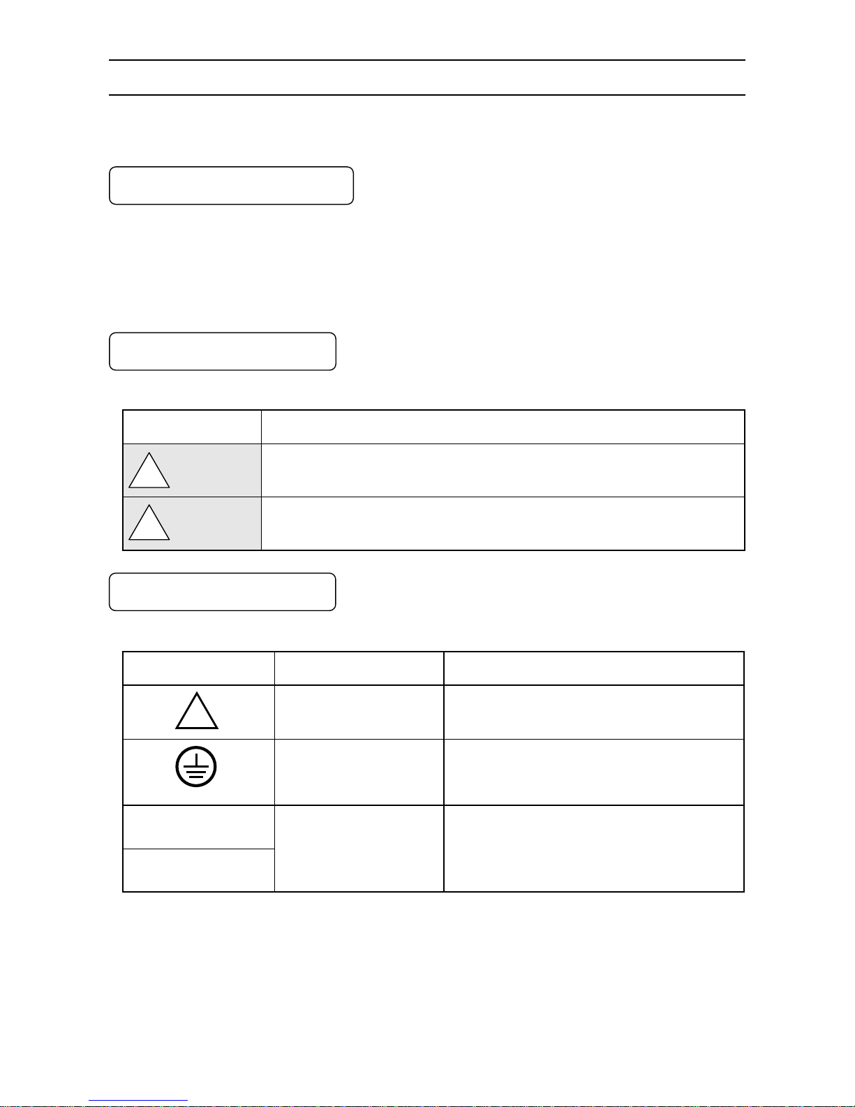
2-2. Symbol Mark
This instruction manual includes the following symbol marks. Make sure to fully understand the meaning of them.
Symbol mark
Meaning
Cautions are explained to avoid causes for death or serious injuries of users.
Cautions are explained to avoid causes for slight injuries of users or damages of the unit
or peripheral devices.
2-3. Label
For safe use of the unit, the following labels are used.
Label
”Name” and place
Meaning
“Alert symbol mark”
Various terminals
(back side)
Place to be handled with cautions to avoid “electric
shock”, “injuries”, etc.
“Protective conductor
terminal”
Right side of power terminal
(back side)
Terminal to be grounded to avoid electric shock
100 to 240V AC
50/60Hz, 40VA
“Power source specification”
Power conductor terminals
Specification of power (voltage range, frequency,
and power consumption) used for the unit
!
!
Warning
!
Caution
Page 8
- 5 -
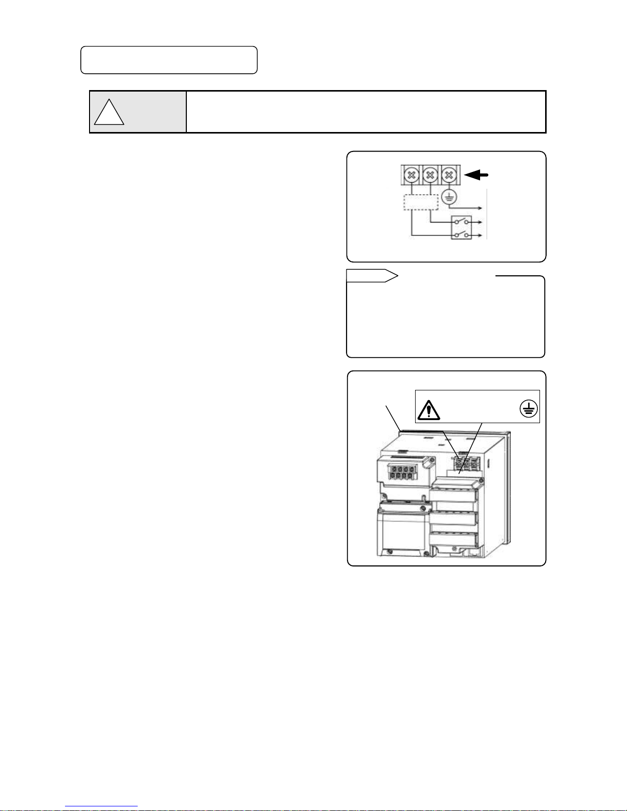
2-4. Important Explanation
To avoid severe accidents, make sure to read and understand the following.
1. Switch and overcurrent protection device
This unit is not provided with a replaceable overcurrent
protective device. Prepare a switch and an overcurrent
protective device for the power supply (circuit breakers,
circuit protectors or the like) within 3m of this unit in a
location where the operator can access easily. Use a switch
and an overcurrent protective device conforming to
IEC60947-1 and IEC60947-3.
2. Be sure to ground this instrument
To avoid electric shock, before turning the power on,
connect the protective conductor terminal of this recorder to
the protective conductor of the power supply equipment,
and do not remove it during use.
3. Before turning on the power supply
For safety, first check that the power source is within the
range indicated on the power label, and then turn on the
external power switch.
4. Avoid repair and modification
Avoid repair and modification with parts replacement by
persons other than service personnel authorized by CHINO.
Not only damage or malfunction of this recorder may occur,
but also dangers such as electric shock may occur. In
addition, the inner unit does not have to be pulled out in the
normal use.
5. Use the unit following the instruction
manual
For safe use, use the unit following the instruction manual.
Please note that CHINO does not have any responsibilities
for any claims for failures or damages occurred with abuse
or misuse of this recorder.
6. Installing the safety device
Regarding the use of a device that anticipates a big loss due to failure of the controller and the peripheral device,
always install a safety device for preventing these losses and implement fail safe design in the final product.
Do not use it in important in facilities like, human life,atomic energy, aviation and space.
7. Turn off the power supply if abnormality occurs
Turn off the power supply immediately and contact your local CHINO’s sales office if any abnormal odor, noise or
any smoke occurs, or if this unit becomes high temperature that is too hot to be touched.
8. Do not put hands in this product
Do not put your hands or tools inside of this product. It may cause electric shock or injuries.
There is no operation such as pulling out an inner unit or using tools when using this product.
Overcurrent
protection
device
Switch
!
Warning
Power terminal
Protective
conductor
terminal
Power label
100 to 240V AC
50/60Hz 40VA
To the protective
conductor of
power supply
facility
Power/protective
conductor
terminal
Power source
For safety, the fuse below is included in the
power unit of the unit. It cannot be replaced.
Manufacturer:Daito Communication
Apparatus Co.,Ltd
Model: SBL32
Fuse in power unit
Reference
Page 9
- 6 -
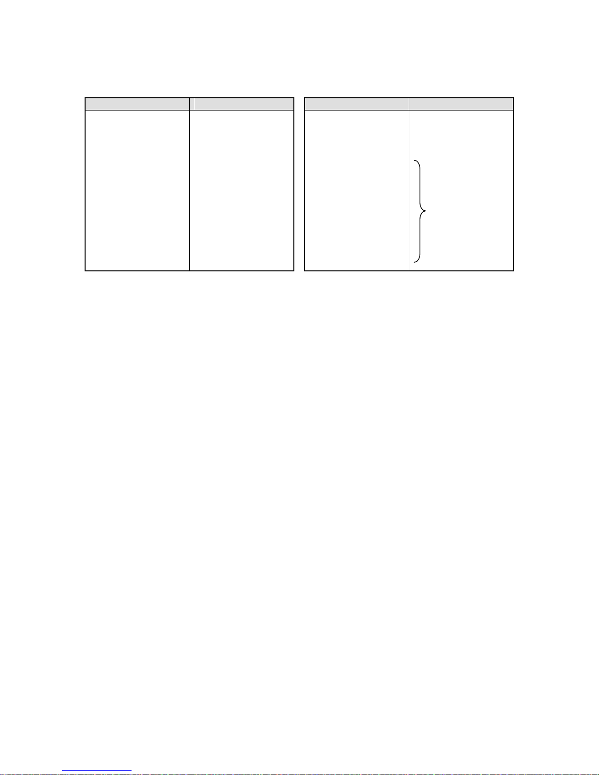
3. Model Code List
AL47□□-□□□-□□□
Input point
06: 6 points
Communications
N: None
E: Ethernet
R: RS232C
A: RS422A/RS485
Q: RS232C + RS485
C: RS422A/RS485 + RS485
G: Ethernet + RS422A/RS485 + RS485
F: Ethernet + RS422A/RS485 + RS485 + Low-order communications
Alarm output + remote contacts
0: None
2: 2 mechanical relay 'a' contact alarm outputs
4: 4 mechanical relay 'c' contact alarm outputs + 5 remote contacts
A: 6 mechanical relay 'a' contact alarm outputs + 5 remote contacts
Power
A: 100 to 240V AC
For OP/SP
NNN: None
NNP: SD card playback
Page 10
- 7 -
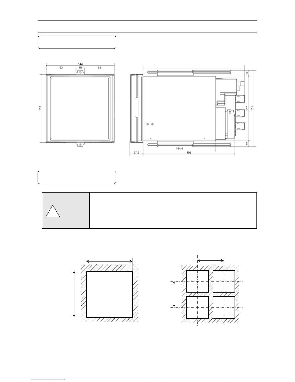
4. Mounting and Wiring
4-1. External Dimensions
Following dimensions are measured while the brackets are attached to the unit.
Unit: mm
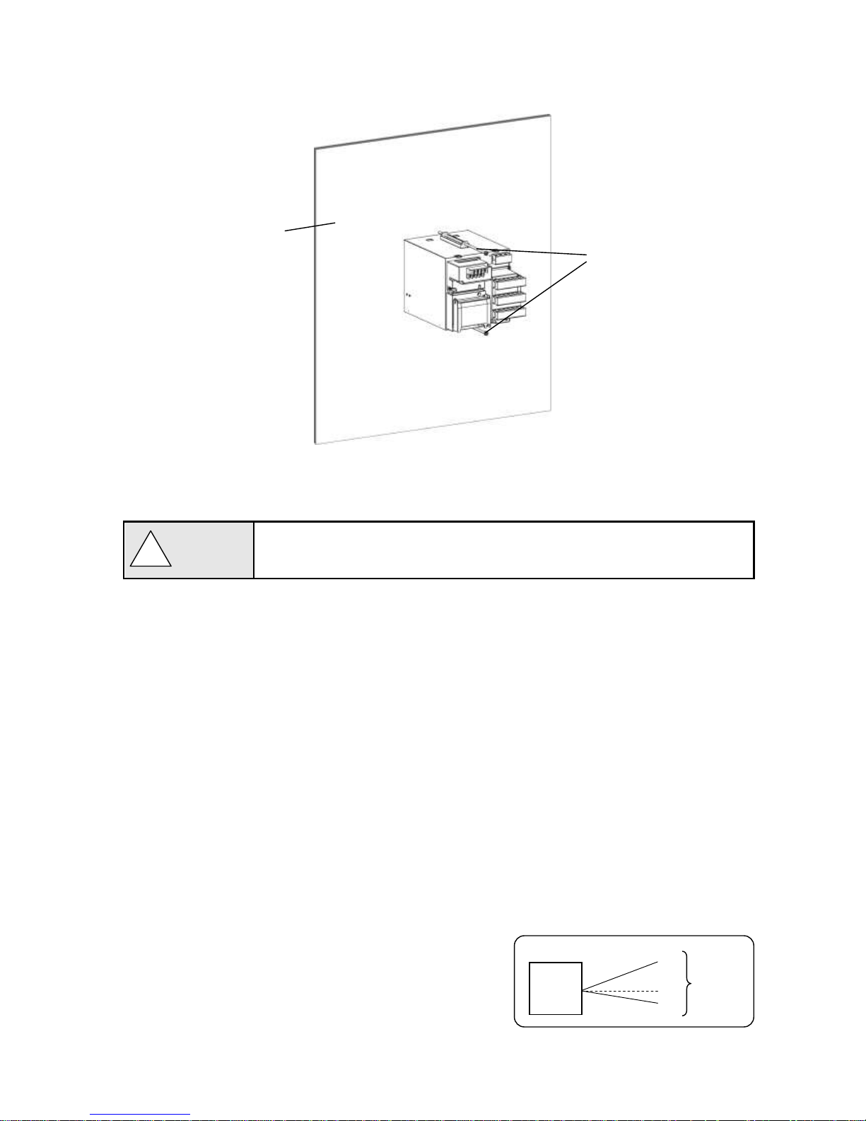
4-2. Mounting
(1) Use the recorder mounting on an indoor installed instrumentation panel.
(2) Brackets can be attached to a panel of steel with thickness of 2 to 6mm or
equivalent strength.
Select thickness of a panel considering weight and depth of the unit with panel
formation for actual use.
(3) For mounting the recorder on the panel, be careful of injury by dropping it.
1. Panel cutout and mounting method
Unit: mm
138
+1
0
138
200
200
● Minimum interval on multiple
units mounting
!
Caution
216 When alarm output/remote contacts unit and communication unit are added
Page 11
- 8 -
(1) Insert the unit into the panel cutout from the front of the panel.
(2) Fix the unit to the panel using the brackets (tightening torque: 1.0Nm). Brackets are attached to the top and
bottom surfaces.
2. Mounting condition
To avoid accidents, make sure to read and understand the following.
Industrial environment
Select a location distant from sources of electric field or magnetic field and without mechanical vibration or shock.
● Overvoltage category ...... II (EN standard) ● Altitude ........................... 2000m or less
● Pollution degree .............. 2 (EN standard) ● Working place ................ Indoor
Normal operating condition
● Ambient temperature ··· 0 to 50℃(20 to 65%RH,non-condensing)
● Ambient humidity ········· 20 to 80%RH,non-condensing(5 to 45℃)
● Power voltage ············· General specification : 100 to 240V AC ±10%
● Power frequency ········· General specification : 50/60Hz ±2%
Atmosphere
● For safety, avoid a location with corrosive gas, explosive gas, flammable gas and combustible gas.
● Avoid a location with dust, smoke, or steam.
Mounting angle
● Lateral tilting ················ 0 to 10°
● Longitudinal tilting ······· Forward tilting: 0°Backward tilting: 0 to 30°
● View angle ··················· -10 to +30°with the horizon as the standard
Angles other than the above affect the recording operation.
!
Caution
Indicator
View angle
About 30°
About 10°
Panel thickness
(2 to 6mm)
Brackets
Page 12
- 9 -
4-3. Wiring
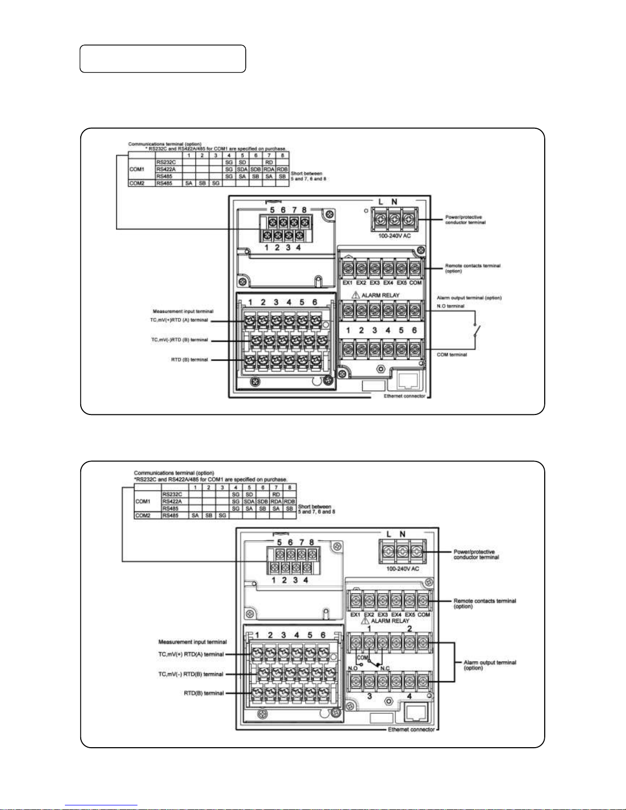
1. Terminal board diagram
The figure below is the diagram of the terminal board with the option [Alarm relay output (6 points ‘a’ contact) +
remote contacts and communication interface].
The figure below is the diagram of the terminal board with the option [Alarm relay output (4 points ‘c’ contact) +
remote contacts (20 points) and communication interface].
Page 13
- 10 -
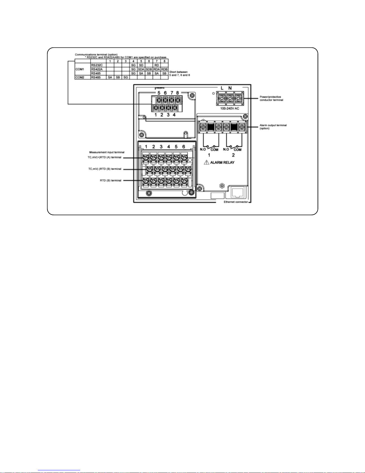
The figure below is the diagram of the terminal board with the option [Alarm relay output (2 points ‘a’ contact) and
communication interface].
Page 14
- 11 -
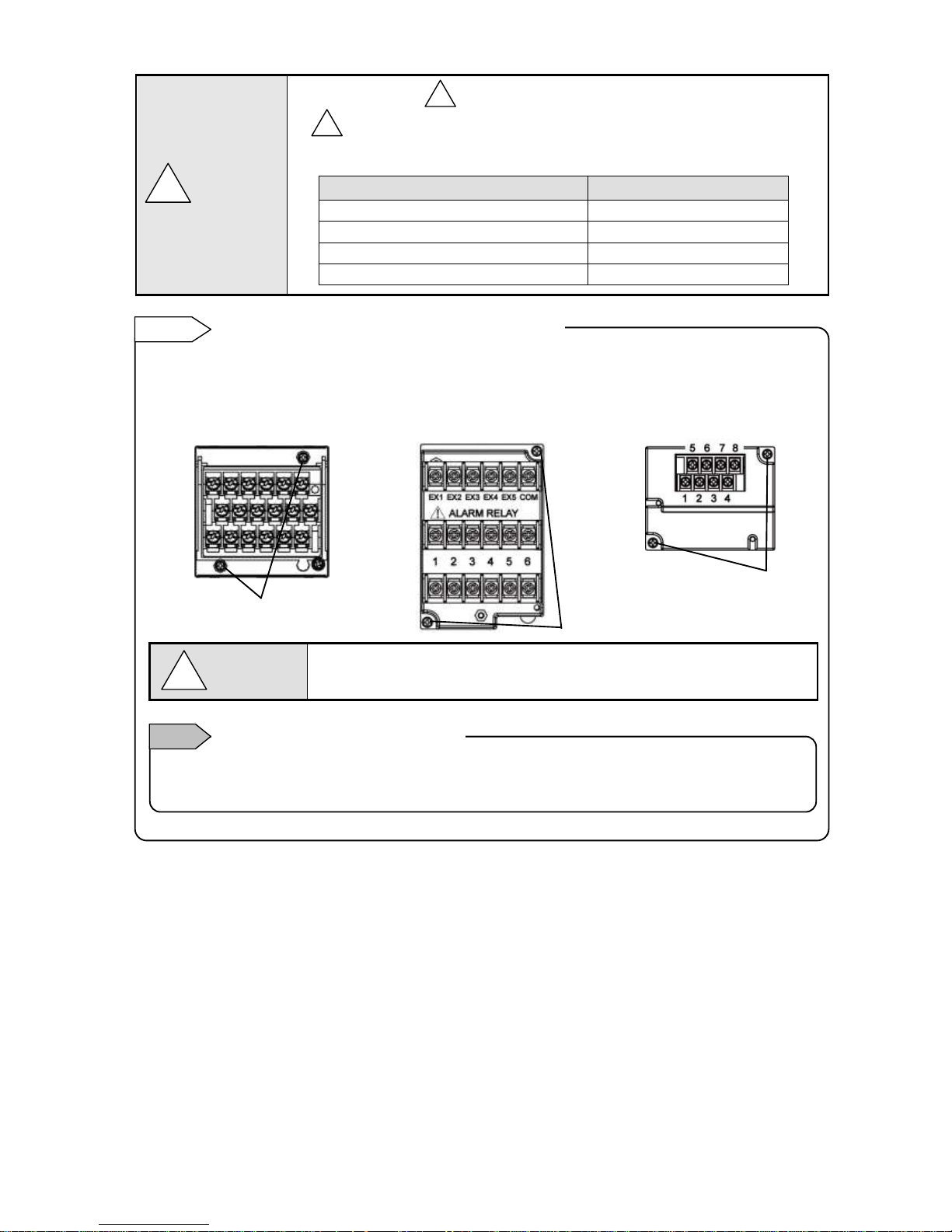
Alert symbol mark ( ) and location
mark is attached to the location to which if human body touches, an electric shock
may be generated.
Terminal name
Location of attached mark
Power terminal
Lower left of power terminal
Measurement input terminal
Upper left of terminal cover
Mechanical relay ‘c’ contact alarm terminal
Upper left of terminal cover
Mechanical relay ‘a’ contact alarm terminal
Lower left of N.O terminal
!
!
!
Warning
For easy wiring, the input unit, alarm output/remote contacts unit, and communication unit are removable.
(1) Every unit can be removed when two mouting screws are removed.
(2) The recorder and each unit are connected with a connector.
Turn off the power and then remove/attach
Make sure to turn off the external power switch before units are removed/attached
to prevent damages on electric circuits.
Input terminal block and alarm terminal block are removable.
Reference
Only thermocouple input unit cannot be replaced with other instrument unit. If done so, measurement errors
are generated.
Note
Thermocouple input unit replacement
!
Warning
[Alarm output/remote contacts unit]
[Input unit]
[Communications unit]
Mounting screws
Mounting screws
Mounting screws
Page 15

- 12 -
2. Precautions on wiring
Precautions on wiring are described below. Observe them to maintain safety and reliability.
1) Feed power source
For the power source for the unit, use the single-phase power source with stable voltage and without
waveform strain to prevent malfunctions.
(1) Switch and overcurrent protective device
Add a switch and overcurrent protective device (250V,3A) to the feed power source
to prevent an electric shock on wiring. The unit has no replaceable fuse.
(2) Connect after the power source is turned OFF
When performing power and input/output wiring, make sure to turn OFF the feed
power source to prevent an electric shock.
2) Separate from strong power circuits
For input/output wiring, avoid adjacency or parallel with strong power circuits such as power lines. Separate
50cm or more for adjacency or parallel.
3) Separate thermocouple input from heat sources.
To reduce reference junction compensation errors for thermocouple input, especially separate terminals
from heat sources (heating body). Also, avoid radiation such as direct sunlight.
4) Separate from noise sources.
Separate from noise sources as much as possible. Unexpected troubles may occur. If separation from
noise sources is disabled, implement countermeasures.
Main source
Countermeasures
Electromagnetic switch or others
Power line with distortion of wave
Inverter
Thyristor regulator
Insert noise filters between power source and input/output
terminals. CR filters are used in many cases.
!
Warning
Page 16
- 13 -
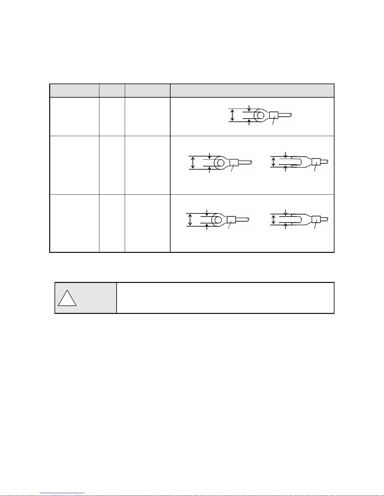
5) Use crimping terminals.
(1) To prevent looseness or disconnection of terminals and short circuit between terminals, install
crimping terminals to termination of connection cables.
(2) To prevent an electric shock, use crimping terminals with insulation sleeves.
Terminal Type and Termination Treatment
Terminal board
Diameter
Tightening torque
Termination treatment (Unit: mm)
Power/Protective
conductor
M4
1.2Nm
O type
Terminals other
than the above
M3.5
0.8Nm
O type Y type
* Be sure to use O type for the alarm output terminals.
* For other terminals, use also O type as possible.
Communications
terminal
M3
0.5Nm
O type Y type
* Use O type as possible.
6) Unused terminals
Avoid using unused terminals for relaying. Electric circuits may be damaged.
Treat properly the wired cables.
Treat surely wired cables not to get hung up on people and things.
Disconnection of wiring with hanging up may cause an electric shock.
8.5 or less
4.3 or less
t: 0.8
With an insulation sleeve
8 or less
3.7 or more
With an insulation sleeve
8 or less
3.7 ormore
t: 0.8
With an insulation sleeve
5.2 or less
3.2 or more
t: 0.8
With an insulation
sleeve
5.2 or less
3.2 or more
With an insulation sleeve
t: 0.8
!
Warning
Page 17
- 14 -
After wiring, install the
terminal cover.
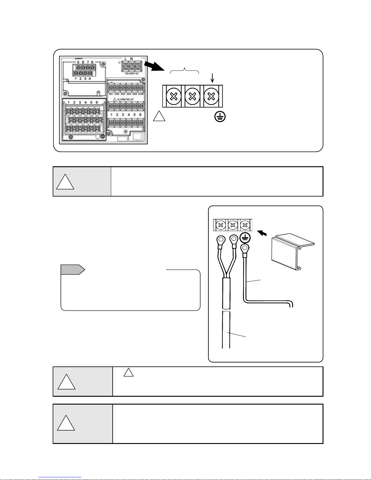
L
N
Copper cable (green/yellow)
with 2mm2 of wire or more
Make sure to connect to
protective conductor of power
facility.
600V vinyl insulated
cable
Power source
3. Power/protective conductor terminals wiring
1) Power/protective conductor terminals
Turn OFF feed power source.
Before power/protective conductor terminals wiring, make sure to turn off the feed power
source to prevent an electric shock.
2) Power terminal wiring
Using 600V vinyl insulated cables as the power line,
install crimping terminals with insulation sleeves to the
termination for wiring.
Note: Use the following standard cables.
(1) IEC 60227-3
(2) ANSI/UL817
(3) CSA C22.2 No.21/49
3) Protective conductor terminal wiring
Make sure to connect to the protective conductor of the
power equipment. Install crimping terminals with
insulation sleeves for wiring.
Grounding wire: Copper cable with wire diameter
2mm2 or more (green/yellow)
mark at power terminals
After wiring the power terminals have power supply voltage applied. Make sure to install
power terminal covers after wiring to prevent an electric shock.
Pay attention to power supply voltage and noise.
The power supply voltage of the unit is indicated on power terminals. Applying power
other than the indicated one causes accidents or malfunction. In addition, if the power
has noise interference, implement countermeasures such as noise cut transformer
installation.
!
!
Warning
!
Warning
!
Caution
Display based on CSA standard in Canada. The live side
of single-phase AC power supply is L, and the neutral
side is N display. To get sufficient performance, observe
the L/N wiring.
L/N display of power terminal
Note
Power terminal
L
N
Protective
conductor terminal
100 to 240V AC
50/60Hz 40VA MAX
Power (voltage, frequency, and power consumption)
!
Page 18
- 15 -
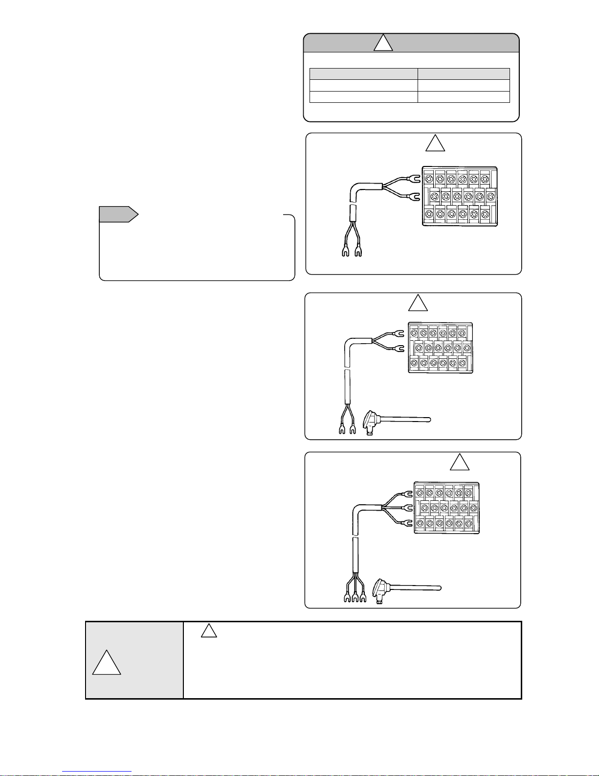
4) Measurement input terminals wiring
1) Measurement input terminal
Turn OFF the feed power source before
wiring to prevent an electric shock.
Install crimping terminals with insulation
sleeves to input terminals for wiring.
2) DC voltage (current) input wiring
Use instrumentation twisted cables for
measures against noise as input cables.
For current input, connect the shunt resistor
for current input to the channel to be
measured before wiring.
3) Thermocouple (TC) input wiring
Make sure to wire thermocouple cable (or
compensation lead wire) to input terminals of
the unit.
If a copper conductive wire is connected
halfway, big measurement error will be
generated.
In addition, avoid parallel connection of a pair
of thermocouple wires with other instruments
(controller or others) that causes troubles.
4) Resistance thermometer (RTD) input wiring
To prevent measurement errors, use 3-core
cables as the input cable in which lines have
the same resistance.
In addition, one resistance thermometer
cannot be connected in parallel with other
instruments (a controller or others).
mark on measurement input terminals
High voltage may be applied to the measurement input terminals due to common mode
noise. Allowable noise value is 30VAC or 60VDC or less. Check that the voltage is equal
to or less than the allowable value. Install terminal covers after wiring to prevent an
electric shock and protect input cables. For thermocouple input, installing terminal
covers reduces reference junction compensation errors.
!
Instrumentation
twisted cable
DC voltage input
(+)
(-)
1 2 3 4 5 6
DC voltage (current) input
!
Resistance thermometer (RTD) input
3-core cable (Same line
diameter, same length)
Note: Cable resistance per 1 cable is 10Ω or less.
3 lines have the same resistance.
1 2 3 4 5 6
Resistance thermometer
A
B
B
!
TC,mV(+) and RTD(A) terminals and TC,mV(-)
and RTD (B “middle”) terminals are insulated
for each channel, and RTD (B”lower”) terminal
shorts internally between channels.
Measurement input termiinsulation
Note
Allowable input voltage
Input type
Allowable input voltage
Voltage, thermocouple input
±10VDC *
Resistance thermometer input
±6VDC
*±60VDC for channels specified with ±10V range or more
Caution
!
Compensation leas wire
Red (+)
White (-)
1 2 3 4 5 6
Thermocouple (TC) input
!
Thermocouple
!
Warning
Page 19
- 16 -
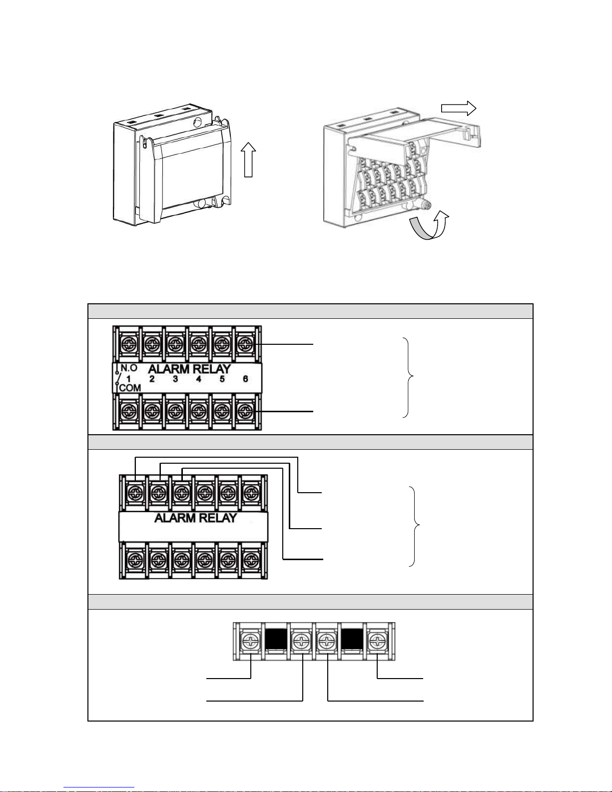
5) Input unit terminal cover mounting/removing
(1) Raise the cover to the direction of the arrow.
(2) Turn to the direction of the arrow.
(3) Pull it to the direction of the arrow to remove.
5. Alarm output terminals wiring (option)
1) Alarm output terminals
The terminal configuration depends on the output specification.
Alarm relay output 6 points (‘a’ contact)
Alarm relay output 4 points (‘c’ contact)
Alarm relay output 2 points (‘a’ contact)
(1)
(2)
(3)
N.O terminal (M3.5)
COM terminal (M3.5)
Alarm relay output
(6 points)
COM terminal (M3.5)
N.O terminal (M3.5)
COM terminal (M3.5)
N.O terminal (M3.5)
ALARM RELAY
1
2
N.O terminal (M3.5)
COM terminal (M3.5)
Alarm terminal
(4points)
1 2
3 4
N.C terminal (M3.5)
Page 20
- 17 -
2) Wiring
Turn OFF the feed power source and the power source for buffer relay before wiring to prevent an electric
shock.
(1) Wire the cable to the load via the buffer relay.
(2) To the alarm output terminals, type O crimp style terminal with insulation sleeve which is connected to
double insulated signal wire should be connected. ( Refer to P13 )
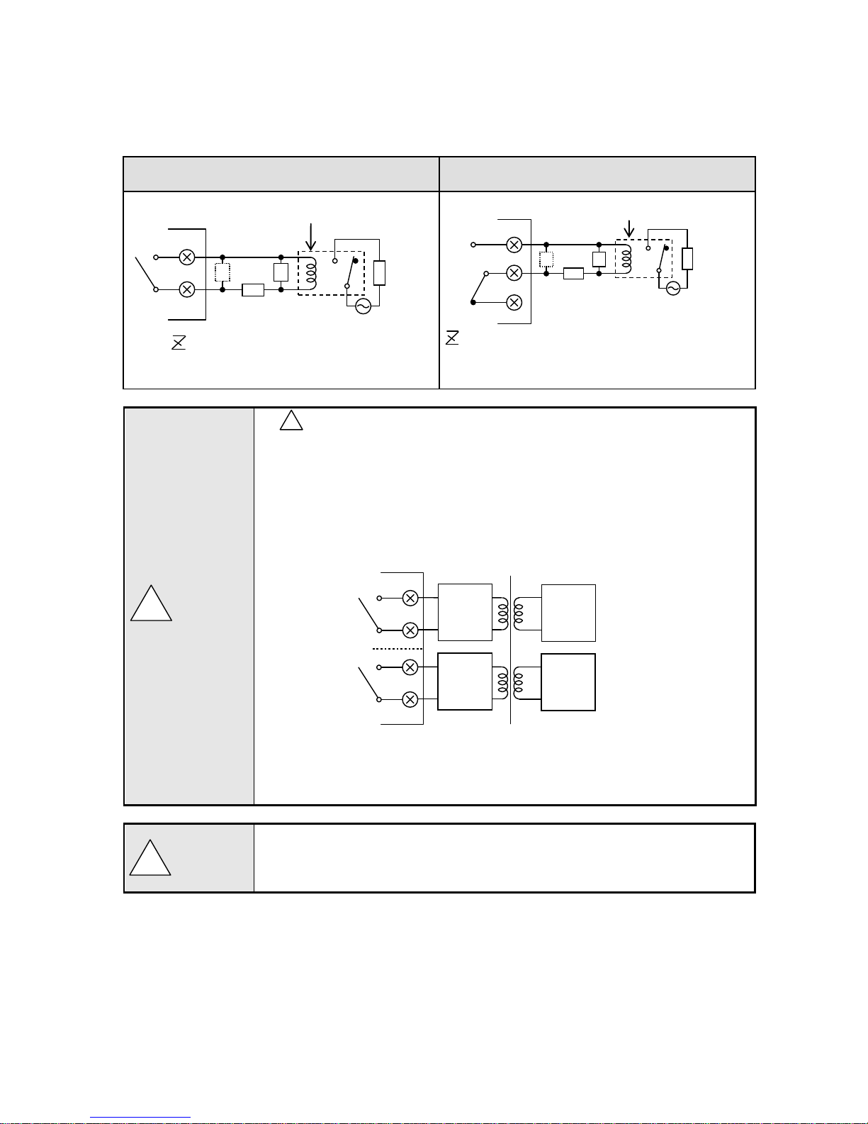
Mechanical relay ‘a’ contact output example
Mechanical relay ‘c’ contact output example
* N.C terminal is opened on alarm occurrence in opposite way to N.O terminal.
mark on alarm output terminals
Maximum of 240VAC can be connected to the alarm output terminals of this unit.
Basic insulation (dielectric strength 1390V) is carried out between the alarm output
channels, however, from the malfunction etc. 240VAC may be output to each alarm
output terminals. Double insulation or reinforced insulation to the outside circuit
connected to an alarm output terminal should be set.
A buffer relay power supply is applied to the alarm output terminals after connections
and so creates a risk of electric shock if touched. Terminal cover must be mounted after
connection. Moreover, safety measures to the outside circuit should be set.
Implement safety measures.
The alarm output of the unit may generate output failure with wrong operation, failure,
abnormal input, or others. Double insulation or reinforced insulation in outside circuit side
of all the channels should be set in any system for safety ensuring.
!
!
Caution
!
Warning
: Contact protective element
(Attachment to a side is desirable.)
N.O
COM b a Z Z
Buffer relay
Recorder
Power
Load
: Contact protective element
(Attachment to a side is desirable.)
Buffer relay
Recorder
Power
Load
Z Z N.C
N.O
COM
b
a
240VAC
Max
Load
240VAC
Max
Load
※
Recorder
※Basic insulation between output channels
Double insulation
or
Reinforced insulation
Page 21
- 18 -
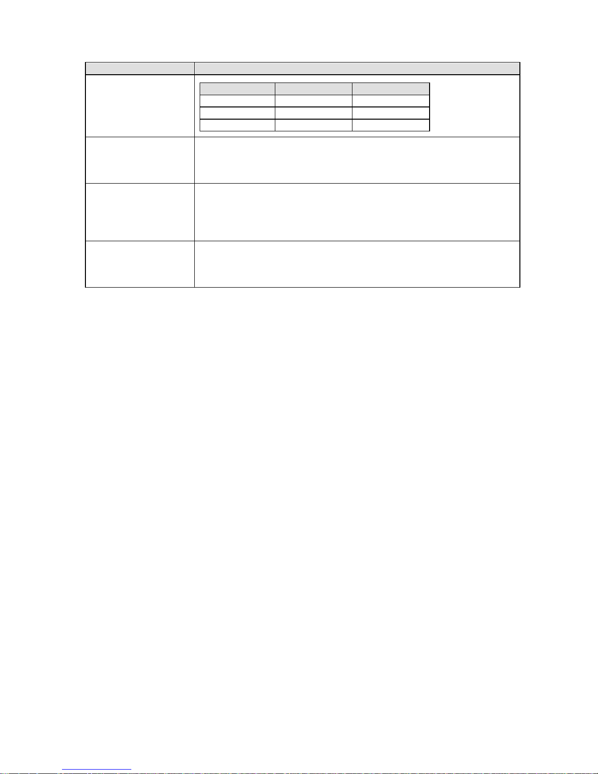
3) Precautions on wiring
The following are precautions on wiring.
Item
Description
Mechanical relay output
specification contact
capacity
(Common to ‘a’ contact
and ‘c’ contact)
Power supply
Resistance load
Inductive load
100VAC
2A
1A
240VAC
2A
1A
30VDC
2A
1A
Contact protective element
Z installation
Install the contact protective element which fits the buffer relay.
It is effective to install the element to the coil side of the buffer relay (see the figure
of mechanical relay ‘a’ contact output example) and prevents wrong operation with
light load.
Selection of buffer relay
Coil rating: Contact capacity or less of output terminals
Contact rating: Double of load current or more
In addition, the coil surge absorption element built-in type relay is recommended. If
there is no buffer relay which meets the load rating, implement another stage of buffer
relay.
Selection of contact
protective element
If there is no surge absorption element built-in buffer relay, install this element.
The element of C/R (capacitor + resistor) is general.
<C/R standard> C: 0.01μF (Rating about 1kv)
R: 100 to 150Ω (Rating about 1W)
(Minimum load)
100μA100mVDC
Page 22
- 19 -
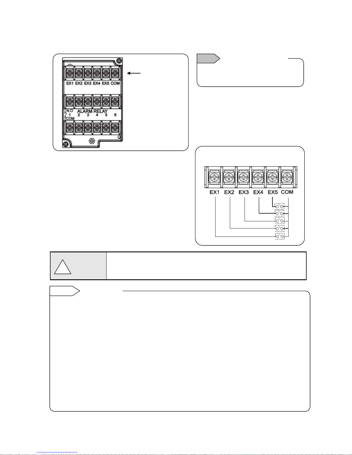
6. Remote contacts terminals wiring and operation selection (option)
Only with remote contacts terminals (option).
1) Remote contacts terminals
2) Wiring
Turn OFF the feed power source before wiring to
prevent an electric shock.
(1) Use no voltage contact signals to be given to the
remote contacts terminals.
(2) Install crimping terminals with insulation sleeves
to remote contacts terminals for wiring.
No voltage contact
For contacts connected to the remote contacts terminals, use switches or relays driven
with voltage level 30VAC or 60VDC or less or manual contacts which support light
load.
■ Wiring example
Voltage on contact open: About 5V
Current on contact short: About 10mA
Note
Characteristics of contact
input terminals
!
Warning
Upper row
Remote contacts
terminals
Remote contact enabled operation name
(1) Recording ON/OFF and three chart speed selection (two terminals of EX1 and EX2 are used)
(2) Messages (No. 01 and 02) selection and printing execution (two terminals of EX1 and EX2 are
used)
(3) Messages (No. 01 to 05) selection and execution (four terminals of EX1 to EX4 are used)
(4) Digital data printing (arbitrary one terminal)
(5) List printing (No. 1 to 3) (arbitrary one terminal for each)
(6) Integration reset (arbitrary one terminal)
(7) Messages No. 01 to 20 printing execution (each arbitrary one terminal)
(8) Time correction execution (arbitrary one terminal)
Each function requires short-circuit for one second or more between COM terminal and each terminal.
Operation allocation
Setting of allocation of operations to each terminal (EX1 to EX5) is required.
Name of operations which require setting
(1) Recording ON/OFF and three chart speed selection (See 8-7. Chart Speed Settings.)
(2) Message selection and printing execution (See 8-14. Message Printing 1 Settings.)
Remote contact
Reference
Page 23
- 20 -
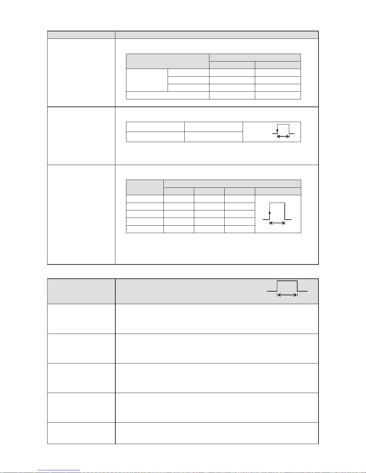
3) Operation for which terminal No. is decided automatically ON: Short-circuit OFF: Open
Operation name
Terminal contact signal
(1) 3 chart speed
selection
3 chart speed setting other than the setting here is required.
(See 8-7. Chart Speed Settings.)
Recording ON/OFF and 3
chart speed selection
Between COM and EX terminals
EX1
EX2
Recording
ON
CS1
OFF
OFF
CS2
ON
OFF
CS3
OFF
ON
Recording OFF
ON
ON
Chart recording must be ON.
(2) Message printing
(No.01 and 02)
Message setting other than the setting here is required.
(See 8-14. Message Printing 1 Settings.)
Message No. 01
COM and EX1
Message No. 02
COM and EX2
At the point when the trigger signals (1 second or more) are given, the selected
message is printed.
Message printing with key is available.
(3) Message printing
(No. 01 to 05)
Message setting other than the setting here is required.
(See 8-14. Message Printing 1 Settings.)
Message
Between COM and EX terminals
EX1
EX2
EX3
EX4 *
No.01
OFF
OFF
OFF
For trigger
No.02
ON
OFF
OFF
No.03
OFF
ON
OFF
No.04
ON
ON
OFF
No.05
OFF
OFF
ON
* After message No. is selected, when the trigger signals (1 second or more)
are given, the selected message is printed.
Chart recording must be ON.
Message printing with key is available.
4) Operation which can be allocated to arbitrary terminal No. ON: Short-circuit OFF: Open
Operation name
Terminal contact signal
(4) Digital data printing
Turn ON the terminal No. specified to “Digital data printing.”
Chart recording must be ON.
Digital data printing with key is enabled.
Even during execution, the acceptance can be repeated only once.
(5) List printing
(List No.1, 2, and 3)
Turn ON the terminal No. specified to “List 1, List 2, or List 3 printing.”
Chart recording must be ON.
List printing with key is available.
(See 8-13. List Printing Settings)
(6) Integration reset
When “Collective reset with remote contacts (EX)” is selected with “Calculation
programming”, turning ON the terminal No. specified to “Integration reset”
resets the integration value.
(See 8-4. Calculation Settings.)
(7) Message printing
(No.01 to No.20)
Message setting other than the setting here is required.
(See 8-14. Message Printing 1 Settings.)
Turn ON the terminal No. specified to “Message printing (No. 01 to 20).”
Chart recording must be ON. Message printing with key is available.
(8) Time correction
When the current time (second) is within 0 to 30 seconds, the time is corrected
to zero second. When it is within 31 to 59 seconds, the time is put forward one
minute and corrected to zero second.
1 sec.or more
For trigger
1 sec.or more
1 sec.or more
Page 24
- 21 -
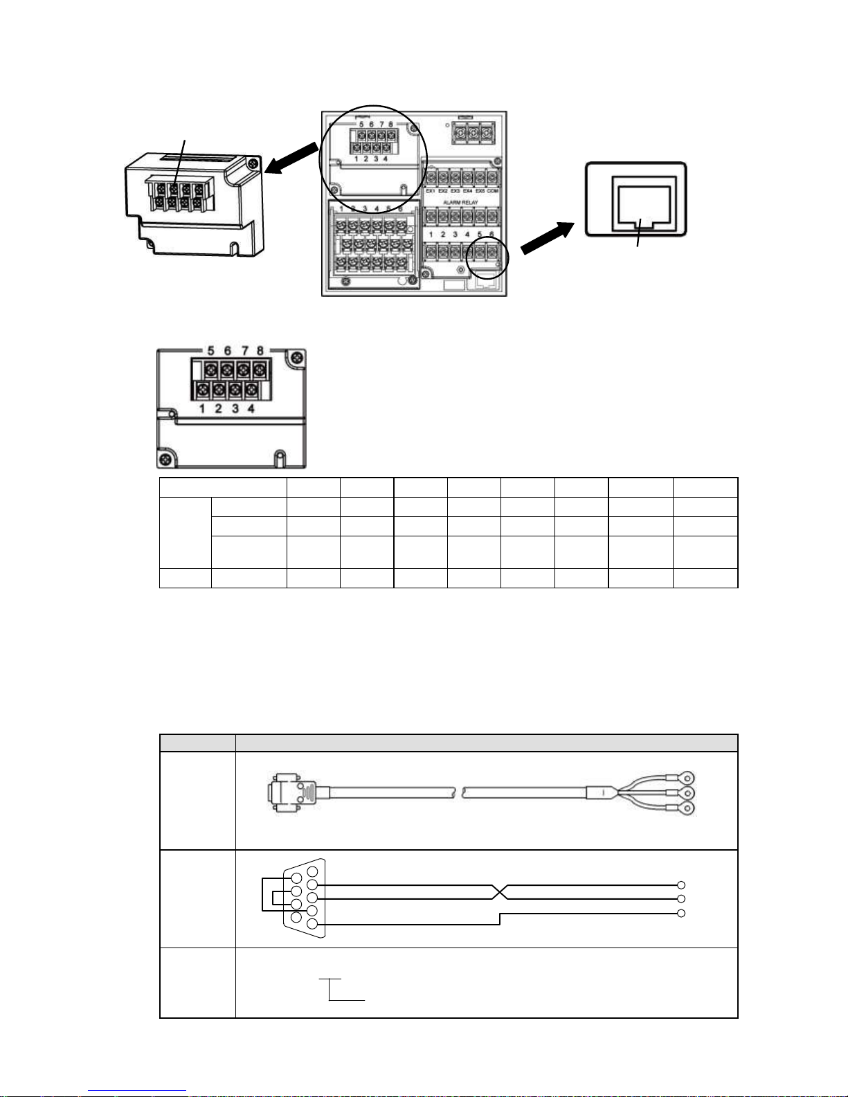
7. Communication I/F terminal wiring (option)
AL4000 can be connected for communications with RS232C, RS422A, RS485, and Ethernet.
1) Communications terminal type (option)
1 2 3 4 5 6 7
8
COM1
RS232C *
SG
SD RD
RS422A *
SG
SDA
SDB
RDA
RDB
RS485 * SG
SA
SB
Short with
SA
Short with
SB
COM2
RS485
SA
SB
SG
* RS232C and RS422A/485 of COM1 are to be specified on purchase.
2) Communications cables
Please prepare communication cables before wiring in advance.
Since exclusive cables are available from us, place an order.
(1) RS232C
Connection between PC and the unit or a line converter
Cable
9-pin connector ↔ Crimp type ring terminals RS232C cable
Shape
Internal
wiring
Model
code
RZ-CRS6□□
Cable length: 01 to 15m (specified)
RD
SD
SG
PC side
9-pin connector
Cable for RS232C (Max.15m)
RD
SD
SG
1
2
3 4 5
6 7 8
9
Ethermet connector
Communications terminals
Page 25
- 22 -
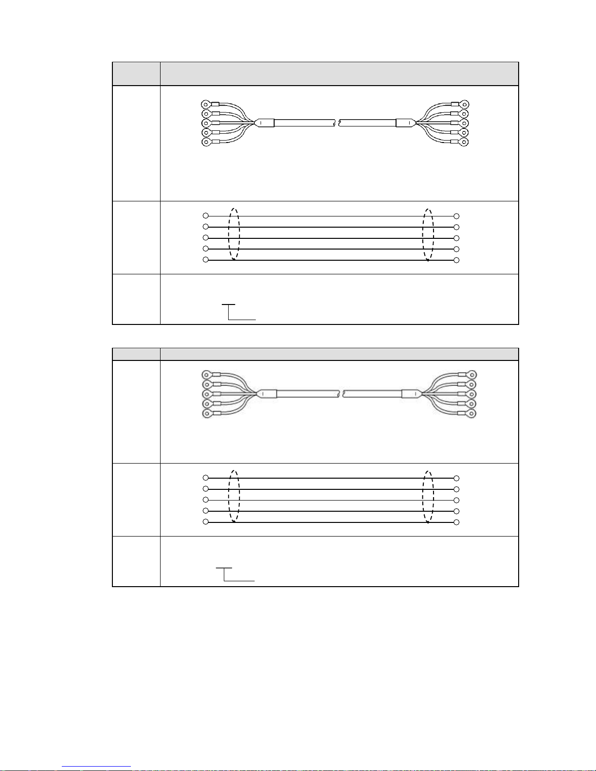
(2) RS422A
Connection between a line converter and the unit
Cable
Crimp type ring terminals ↔ Crimp type ring terminals RS422A cable
(for a line converter)
Shape
4-core cable of twisted 2-core cables of twisted VCTF lines. Each side has a SG
(signal ground) line. Since the line converter has no SG terminal, cut and use the
cable.
Internal
wiring
Model
code
RZ-CRA2□□
Cable length: 01 to 99m (specified)
Connection between the unit and other devices
Cable
Crimp type ring terminals ↔ Crimp type ring terminals RS422A cable (for parallel)
Shape
4-core cable of twisted 2-core cables of twisted VCTF lines. Each side has a SG
(signal ground) line.
Internal
wiring
Model
code
RZ-CRA1□□
Cable length: 01 to 99m (specified)
Line converter side
Recorder side
RDB
RDA
SDA
SDB
SG
SDB
SDA
RDA
RDB
SG
Device side
Recorder side
SDB
SDA
RDA
RDB
SG
SDB
SDA
RDA
RDB
SG
(black)
(white)
(red)
(green)
(blue)
RDA
RDB
SDA
SDB
SG
SDA
SDB
RDA
RDB
SG
(black)
(white)
(red)
(green)
(blue)
(black)
(white)
(red)
(green)
(blue)
SDA
SDB
RDA
RDB
SG
SDA
SDB
RDA
RDB
SG
(black)
(white)
(red)
(green)
(blue)
Page 26
- 23 -
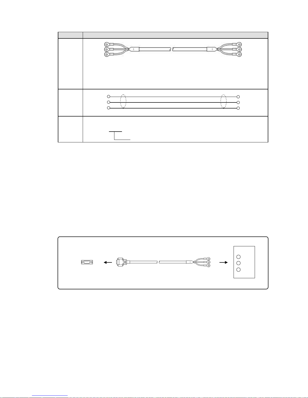
(3) RS485
Connection between the unit and other devices and between a line converter and the unit
Cable
Crimp type ring terminals ↔ Crimp type ring terminals RS485 cable
Shape
2-core cable of twisted CVVS lines. Each side has a SG (signal ground) line. Since
the line converter has no SG terminal, cut and use the cable.
Internal
wiring
Model
code
RZ-LEC□□□
Cable length: 001 to 200m (specified)
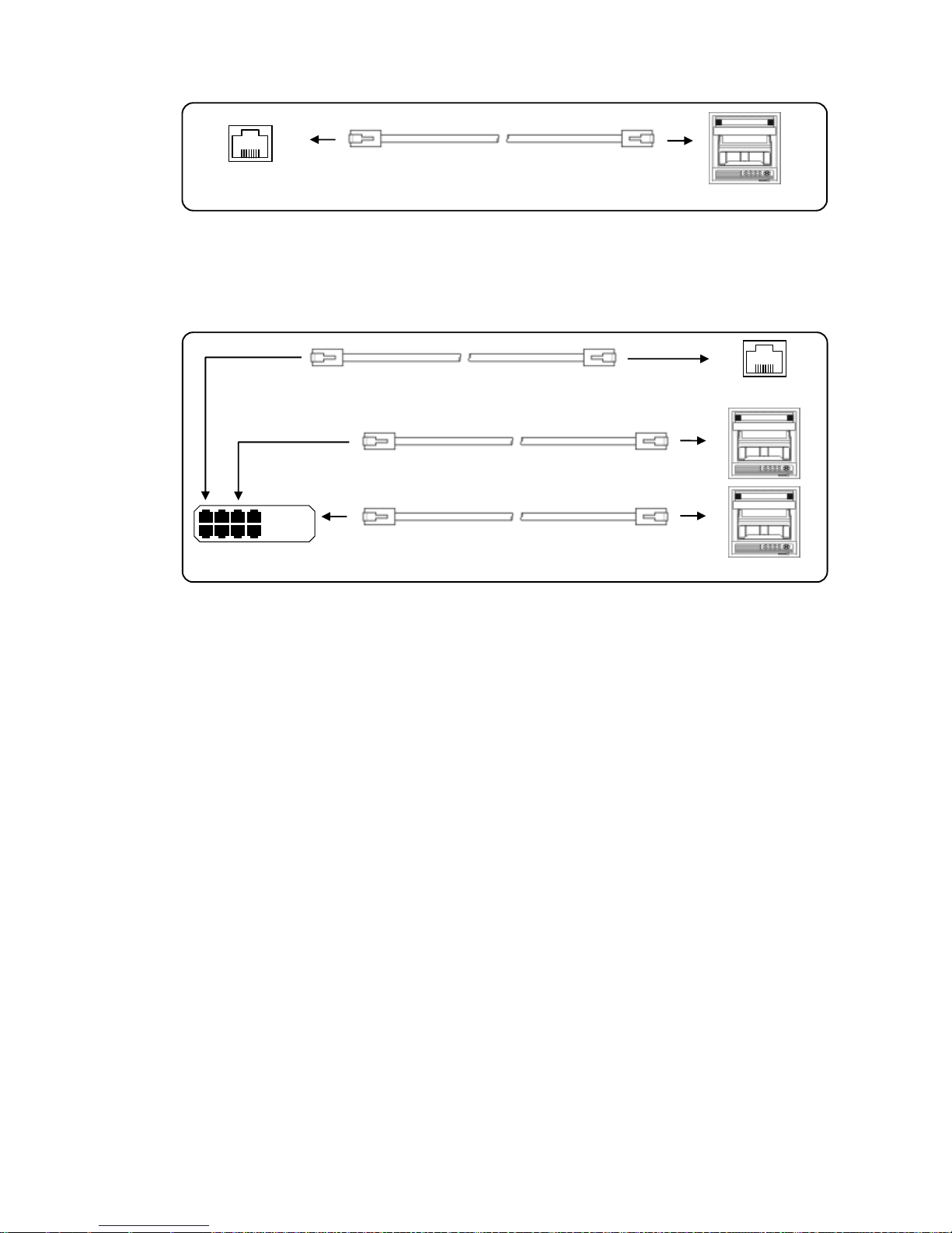
(4) Ethernet
Connection between PC and devices
For direct (one-to-one) connection, use crossover twist-pair cables with shield (available locally as
STP cable).
Connection between HUB and devices (multiple devices can be connected)
For (one-to-N) connection between PC and devices via HUB, use straight twist-pair cables with
shield (available locally as STP cable).
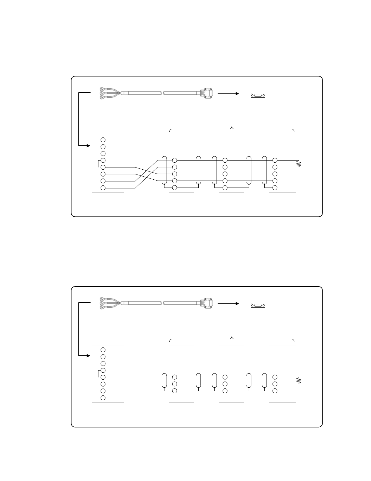
3) Communications line wiring
(1) RS232C wiring
PC and devices are connected one-to-one with RS 232C.
Example of terminal connection
RDA(black)
RDB(white)
SG(green)
(black)SA
(white)SB
(green)SG
Device side, Line converter side
Recorder side
RDA
RDB
SG
SA
SB
SG
SD
RD
SG
Cable for RS232C (Max.15m)
Device side
RZ-CRS6
Communications port
RD
SD
SG
PC side
Page 27
- 24 -
(2) RS422A wiring
PC and multiple devices are connected with RS422A. A line converter is required.
RS422A cable is within 1.2km of total extension and up to 31 devices can be connected.
Install a resistor of 100Ω to the last edge of the transmission line device side.
(General metal film resistors will be fine. They are available from us, place an order.)
Example of terminal connection
(3) RS485 wiring
PC and multiple devices are connected with RS485. A line converter is required.
RS485 cable is within 1.2km of total extension and up to 31 devices can be connected.
Install a resistor of 100Ω to the last edge of the transmission line device side.
(General metal film resistors will be fine. They are available from us, place an order.)
Example of terminal connection
Turn the switch of RS422A/RS485
to RS422A.
Avoid connecting SG line to FG terminal or
gound terminal of the device.
RDB
RDA
SDA
SDB
SG
Termination
resistor
100Ω
Device side
Line converter
SC8-10
RDB
RDA
SDA
SDB
SD
RD
SG
1
2
3
4
5
6
7
8
Cable for RS232C (Max. 15m)
RZ-CRS6
Communications port
PC side
SD
RD
SG
RDB
RDA
SDA
SDB
SG
RDB
RDA
SDA
SDB
SG
SG
RDB
RDA
SD
RD
SG
Turn the switch of RS422A/RS485
to RS485.
Avoid connecting SG line to FG terminal or
gound terminal of the device.
SA
SB
Termination
resistor
100Ω
Device side
Line converter
SC8-10
1
2
3
4
5
6
7
8
Cable for RS232C (Max. 15m)
RZ-CRS6
Communications port
PC side
SD
RD
SG
SA
SB
SG
SA
SB
SG
Page 28
- 25 -
(4) Ethernet wiring
Example of connection between PC and Ethernet devices (one-to-one connection)
Example of connection between PC and HUB/Ethernet devices (one-to-N connection)
Crossover twist-pair cable
with shield (Max.100m)
Device side
PC side
Device side
HUB
Straight twist-pair cable
with shield (Max.100m)
PC side
HUB
Straight twist-pair cable
with shield (Max.100m)
Straight twist-pair cable
with shield (Max.100m)
Page 29
- 26 -
5. Part Names
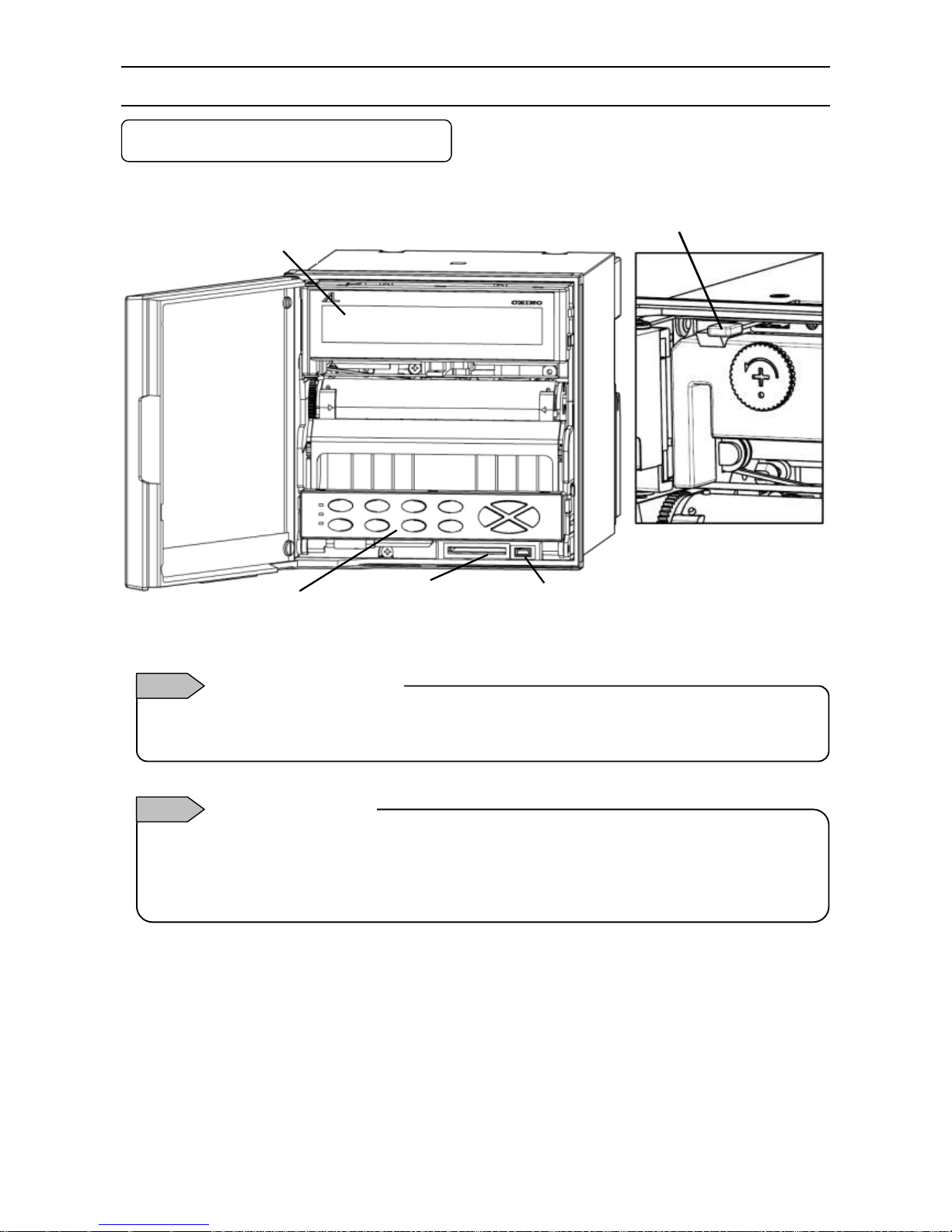
5-1. Front Section of Internal Unit
Enlarged view of power switch
Power switch
Open the display board in the direction same as the unit door.
The power switch is located at the upper left of the unit.
Display
Engineering port
USB communication connector
SD card
slot
Operation/set keys
The front of the door is made of glass. Avoid giving any shock to the glass or giving any strong force to the frame
for preventing any injury due to breakage.
How to handle the door
Note 1
Avoid closing the door in the state of operation/set keys opened. If the door is closed in the state of the
operation/set keys opened, the mechanism of the operation/set keys allows the operation/set keys to be lifted to
the direction for closing to prevent damage; however, behavior for protection is not guaranteed. If the door is
closed forcedly or fast, it may be damaged.
Operation/set key
Note 2
Page 30
- 27 -
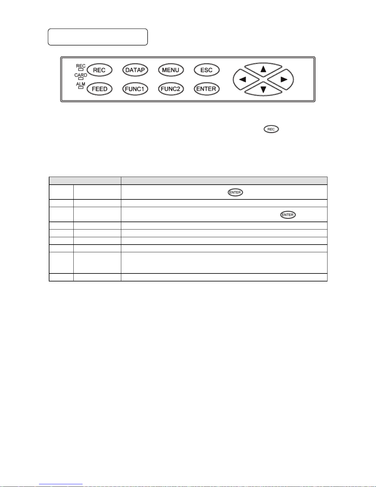
5-2. Operation/Set Keys
Status LED
REC
Lights in green while recording is on. Recording is turned ON/OFF by the
key.
Flashes when chart ends.
CARD
Lights in green when SD card is recognized by the unit, or flashes in a recognition process.
ALM
Flashes in red when alarm occurs.
Key names
Functions
REC
Record key
Turns ON/OFF recording. Used with the key.
FEED
Feed key
Feeds chart at a speed of 600mm/min while this key is pressed.
DATAP
Data print
Prints the data at the time of pressing this key. Used with the key.
FUNC1
Function 1 key
Switches and sets functions (function is shown on the display).
FUNC2
Function 2 key
Switches and sets functions (function is shown on the display).
MENU
Menu key
Displays various setting items.
ESC
Escape key
Returns to the previously displayed screen.
▲/▼
/
Up/Down
Left/Right
Moves the cursor up/down and left/right.
Used also to select setting items or values.
Used also to advance the channel number.
ENTER
Enter key
Used to register various settings.
Page 31

- 28 -
6. Operation
6-1. Preparation for Operation
1. How to set chart paper
1. Pulling out the chart cassette
(1) Open the unit door and pull the operation/set
keys part.
(2) Hold the chart cassette grip and pull it toward
you.
2. Setting chart paper
(1) Open the chart guide and chart feeding holder.
(2) Loosen the both ends of chart to prevent double
feed.
(3) Set chart in the chart housing at the back of the
chart cassette. The “round” hole and “oval” hole
should be at the left and right side of the chart
respectively.
(4) Draw out chart approximately 20cm and set
holes on the both ends to the sprockets of the
chart drum. Put two or three folds of chart in the
chart tray at the front of the chart cassette and
then close the chart guide and chart feeding
holder opened in the step (1).
(5) Turn the thumb wheel downward and make sure
that the holes on the both ends of chart are not
released from the sprockets, and feeding is
smoothly done.
3. Returning the chart cassette to the inside of
the unit
(1) Align the guide of the chart cassette with the
guide rail located at the both sides of the
internal chassis and then insert the cassette
until it is locked.
(2) Put back the operation/set keys part.
(3) Operate the key to check if the chart is
fed properly and smoothly. If not, reset the chart
again.
Chart feeding holder
Chart guide
Thumb wheel
Chart cassette grip
Operation/set keys part
Be careful of injury by dropping the chart cassette after
pulling it from inner unit. Take care not to catch your
fingers in the unit when putting the chart cassette back.
Handling of chart cassette
Note
Page 32

- 29 -
2. How to attach ribbon cassette
1. Preparation
(1) Make sure that the unit is turned ON and then
press the key (recording OFF).
(2) The printer stops around the center and the
ribbon holder moves backward.
(3) Prepare a ribbon cassette.
(4) Open the unit door.
(5) Open the display board in the direction same
as the unit door.
2. Attaching ribbon cassette
(1) Insert a ribbon cassette to the left holder
locker.
(2) Put the ribbon under the printer and push the
right side of the ribbon cassette.
(3) Insert the ribbon cassette to the right holder
locker.
(4) Make sure that the ribbon cassette is properly
held by the left and right holder lockers.
(5) Turn the winding knob counterclockwise.
(6) Return the display board in place.
(7) Make sure that the unit is turned ON and then
press the key (recording ON)
(8) Feed the ribbon a few centimeters while recording
is ON. Check the ribbon feeding condition.
3. Preparation for ribbon cassette replacement
(1) Move the printer to the center and the ribbon
holder backward as in the case of attaching a
ribbon cassette.
(2) Open the display board in the direction same as
the unit door.
4. Removing ribbon cassette
(1) Pull the right side of the ribbon cassette to remove
it from the right holder locker (see below tips for
removal).
(2) Pull the ribbon out of the printer.
(3) Pull the left side of the ribbon cassette to remove
it from the left holder locker.
Drive gear
Ribbon
Winding knob
Direction of ribbon
feed
Right
Left
Draw out the ribbon from
the left side and then wind
up by turning the winding
knob.
When winding failure occurs
Ref 1
Left holder locker
Right holder locker
Put the tip of your
index finger on
the top of the
ribbon cassette
and roll it
downward.
Under standard operating conditions
(temperature: 23 ±2°C, humidity: 55 ±10%RH), it
can last about three months. However, it may be
shortened depending on temperature, humidity
or use of the unit (chart speed, intervals of
periodic data printing, etc.).
Replacement cycle of ribbon cassette
Ref 2
When replacing the ribbon cassette, be careful not to
catch your fingers in the unit.
Replacement of ribbon cassette
Note
Page 33

- 30 -
6-2. Basic Operation
1. Power on
Turn the power switch to ON.
Data will be shown on the display after about 10 seconds.
After detecting the initial position, the printer prints the date and time and then feeds chart about 5mm.
2. Switching of display
The unit can provide three display modes.
Either fixed or sequential display can be selected for each display mode (pressing the key switches the
display between AUTO (sequential) and CONST (fixed).
With the sequential display, channel number advances every two seconds (factory default which can be changed).
While holding down the key, press the
/
key to change the display mode.
See “8-24. Display Settings” to set default display mode at power-on.
CH NO.
Measured value
Chart end/recording ON
SD card remaining amount
AUTO/CONST
Data print/list print
CH NO. Chart end/recording
ON
TAG SD card remaining
amount
Measured value
Chart speed
Unit Recording point
indicator
Date/time Key guide
AUTO/CONST
Data print/list print
CH NO.
Measured value
Chart end/recording ON
SD card remaining amount
AUTO/CONST
Data print/list print
↓: ESC + ▲ ↑: ESC + ▼
To switch from “1-point display” to “1-point + bar display”, press the key while holding down the key.
To switch from “1-point display” to “6 point display”, press the key while holding down the key.
The date/time printing is not performed at power-on.
Note 2
While recording is OFF
Backup of settings, clock and display mode are made.
However, channel number is not saved so the data
with smallest channel number within set range will be
dsplayed.
Display backup
Note 1
6-point display
1-point display
1-point + bar display
Page 34

- 31 -
3. Chart recording operation
Recording ON
Recording OFF
* Any of the above settings can be cancelled by pressing the key.
(The setting is cancelled also after around 10 seconds without key operation.)
1) Turning ON/OFF chart recording
Recording can be turned ON/OFF by pressing the key → key.
While recording is ON, the “REC” status LED lights up.
Recording is not performed while it is OFF, but reading inputs, updating data and calculating alarms are
performed. Data printing, list printing and message printing are unavailable.
2) Data printing
Currently executing trace printing is interrupted to print numeric values of the latest measurement data as
shown in the below example.
Press the key → key to perform data printing.
Use the periodic data printing function to perform data printing periodically.
This cannot be performed while recording is OFF or keys are locked.
Colors used for printing changes every time data printing is executed in the following order: red → black →
blue → green → brown → purple (repeated).
Example of data printing
“*** Quit recording? ***”
Pressing the key turns recording OFF.
“*** Start Digital data printing? ***”
Press the key to start.
“*** Start recording? ***”
Pressing the key turns recording ON.
(1) Key operation is unavailable when is shown on the display indicating that keys are locked.
(2) When using remote contacts (optional), key operation becomes unavailable when recording is turned OFF by a
remote contact terminal.
Pressing the key → key becomes invalid in some cases
Note
Operation: Operations including measurement continue without being interrupted.
Cancel: To stop data printing halfway through, press the key → key. The unit will be put into
recording OFF status when the currently printing line is finished. However, the behavior depends on the
unit condition when the instruction is received.
Pressing the key → key later returns to the previous printing status.
Operation during printing and print cancel
Reference
Page 35

- 32 -
3) Chart feed
Chart can be fed using the key.
While the key is pressed, chart is fed at a speed of 600mm/min. When fast-feeding chart,
recording (dot-printing) is stopped.
Feed chart when a measurement target or measurement condition is changed.
4) Aligning time line
When operating the unit with a chart speed of multiples of 10 (mm/H), it is advisable to align the time line
print with the time scale of chart for easier view of the result.
The following shows a bad example.
Time line (print)
Time scale
This is useful only when you use a chart with 10mm-pitch time scale.
(1) There is a time line setting mark () on the right side of the chart guide located at the front of the chart
cassette.
Time line setting mark
(2) Align a time scale line with the setting mark () as viewed from the front by pressing the key
(do not align it manually).
(3) It may be a good idea to set a time scale line 1 to 2mm above the setting mark () to perform a fine
adjustment later.
(4) Press the key and turn off the “REC” status LED.
(5) Press the key at a desired time <xxh 00min> and turn on the “REC” status LED.
(6) After a few hours, check to see if the time line print is aligned with a time scale line. If the time line print
comes behind a time scale line, press the key briefly and see how it works. If it comes ahead,
remove the chart and set it back for a few hours and then try again.
Due to the mechanical nature of the unit, a few millimeters of chart may not be fed. Therefore, we recommend that
chart be fed by the key.
Also, for the same reason, use the key to feed when new chart is set.
Feeding chart
Reference
1 to 2mm above
the setting mark
10mm
Subsidary time scale
Page 36

- 33 -
6-3. Operation
1. Types and contents of chart recording
There are two types of chart recording: trace printing and digital recording/printing. Without setting particular items,
trace printing, channel number printing and fixed time printing are performed while recording is ON.
Item
Contents
Chart recording
Trace printing
Records a trend for each channel by dot printing with different color.
The color can be specified arbitrarily (six colors in total).
Digital recording/printing
Channel number printing
Prints channel number interlocking with chart speed.
Alarm printing
Prints time or alarm point when alarm is generated/cleared.
Periodic data printing
Adds digital record/print on a trace print in desired intervals.
Data printing
Performs digital recording/printing when required, suspending trace
printing.
List printing
Prints a list of all or specified parameters when required.
Fixed time printing
Prints date, time/time line, max/min chart record, channel number,
tag and unit interlocking with chart speed.
Message printing
Prints a message which can contain up to 40 characters.
Calendar timer printing
Prints data when both calendar timer and printing are set to ON.
Operation recording
When using remote contacts (optional), the status of remote input
No. (ON/OFF) is printed at the specified position with a bar line.
Setting change mark
When setting is changed, “Δ” is printed at the right side of chart.
Power-on time printing
Date and time are printed at power-on.
Example of trace printing and fixed time printing
Page 37

- 34 -
2. Fixed time printing interval
When recording is ON at the time of power-on, fixed time printing is performed first.
The following table shows printing intervals which vary depending on the printing item.
Time and time line
Channel number
Chart speed
Max/min chart record, tag
and unit
Varies depending on
the chart speed
At approx. 6mm intervals,
in order of ascending
channel number
At approx. 84mm
intervals
At approx. 42mm intervals,
in order of ascending
channel number
1) Printing intervals of time and time line
Time and time line are printed at the following intervals which vary by the chart speed. The start point of the
intervals is 00h 00min.
Chart speed (mm/H)
Time and time line (*)
Time line only
Year/month/date
1 - 9
12h 00min only
6h
00h 00min only
10 - 15
4h
2h
16 - 30
2h
1h
31 - 60
1h
←
61 - 119
1h
30min
120 or higher
30min
←
(*) When periodic data printing occurs at the same time, only time line is printed.
2) Printing interval of channel number
(1) Channel number is printed beside the trace
printing (normally at the right of it) at 6mm
intervals in order of ascending channel number,
using the color same as the trace printing.
(2) The interval between channel 6 and 1 is
approx. 12mm.
(3) When you skip channels, there will be
additional break interval (in addition to the
12mm-break), according to the number of
channels skipped.
3) Printing interval of chart speed
Chart speed is printed in black at the left side of chart after every two cycles (approx. 84mm) of channel
number.
4) Printing interval of max/min chart record, tag and unit
(1) These items are printed at the left and right sides of chart in order of ascending channel number after
every single cycle (approx. 42mm) of channel number.
(2) In accordance with the channel number, maximum/minimum chart record, tag and unit are printed
using the color same as the dot printing.
(3) Tag is not printed if not specified.
(4) When you set the recording format, printing contents vary depending on the selected format.
Standard (Standard), automatic range-shift (Auto Range)
Note: When Auto Range is used, the max/min chart record of the range (one of the ranges R1 to R5) used at
the time of printing will be printed.
Compressed/expanded printing (Comp. & Exp.Print)
Zone printing (Zone Print)
+ + …*
1: TIC1 °C
0.0/200.0/400.0/500.0
zero
1st break point 2nd break point
span
+ + …*
1: TIC1 °C
0.0 500.0
* A “+” mark is printed at the first and second break
points.
* A “+” mark is printed at the edge of the printing area
to indicate it.
Tag
Channel No.
Minimum chart record
Channel No.
Maximum chart record
Unit
Trace printing
1: TIC1
0.0
1
500.0
°C
6 1 2 3 4
5
(Without skipping)
Printing channel number
(Skipping channel 4)
1
2
3 5 6
One cycle ≈ 6mm x 7 ≈ 42mm
Page 38

- 35 -
3. Restrictions on recording
1) Digital recording/printing unavailable at certain chart speeds
When chart speed is set to 251mm/H or higher, all digital recordings/printings will not be performed and
only trace printing is performed. However, time line printing, power-on printing, data printing and list printing
can be performed.
2) Dotting interval
Dot printing is performed at intervals of 5sec/point at normal speed, and 2.5sec/point at high speed. To
prevent damage to chart caused by overlapping of dots, dotting interval becomes longer as chart speed
decreases.
The chart speed interlock mode is also available, which performs dot printing depending on the chart
speed.
Normal dot printing (approx. 5sec/point)
Fast dot printing (approx. 2.5sec/point)
The restriction expressed by the following will be placed when chart speed drops below a certain value.
Dot printing interval (sec/point) ≈
<Without skipping>
CS (mm/H)
Interval
CS (mm/H)
Interval
1
Approx.
30sec
5
Approx.
6sec
2
Approx.
15sec
6
Approx.
5sec
3
Approx.
10sec
7
4
Approx.
8sec
8
For 6mm/H or higher CS, interval is fixed to approx.
5sec/point.
<Without skipping>
CS(mm/H)
Interval
CS(mm/H)
Interval
1
Approx.
30sec
6, 7
Approx.
5sec
2
Approx.
15sec
8, 9
Approx.
4sec
3
Approx.
10sec
10, 11
Approx.
3sec
4
Approx.
8sec
12, 13
Approx.
2.5sec
5
Approx.
6sec
14 -
For 12mm/H or higher CS, interval is fixed to approx.
2.5sec/point.
3) Overlapping of digital recording/printing
The following order of priority is used for printing generally when printing positions of different items
overlap.
(1) Data printing/list printing > time line printing > periodic data printing > alarm printing = fixed time
printing = message printing
(2) The order of priority for fixed time printing is as follows:
Time line > time = channel number = chart speed = max/min chart record, unit and tag
Examples and special cases are described below.
Case 1: Data printing/list printing occurs while recording/printing.
Currently executing printing process is interrupted to execute data printing/list printing.
Note: Printing characters will be split due to the interruption.
Case 2: Time line/time printing occurs while periodic data printing is in progress.
Only time line is printed. Time is not printed.
Case 3: Fixed time printing occurs when periodic data printing has short intervals.
The intervals of fixed time printing may be extended, or the printing itself may not be performed.
Case 4: Alarm printing overlaps with max/min chart record, unit and tag.
The max chart record and unit are replaced by alarm print.
180 CS: chart speed
CS x CH CH: number of channels
Page 39

- 36 -
4. Abnormal input
1) Out-of-range input
When an input is out of the chart printing
range or measuring range, the unit indicates it by
the following display or printing.
Measuring range: determined by the input type
described in “8-2. Input Type
Settings”.
Chart printing range: trace printing range described
in “8-2. Input Type Settings”.
No.
Input status
Display
Printing
Digital
Digital
Trace
(1)
Input under the lower limit of
measuring range*
-OVER
-OVER
Downscale burnout
(2)
Input under the lower limit of
chart printing range
Normal display
Normal print
(3)
Input over the upper limit of
chart printing range
Normal display
Normal print
Upscale burnout
(4)
Input over the upper limit of
measuring range*
+OVER
+OVER
* Digital display/printing is available for an input outside the measuring range if it is within ±10% of the span.
2) Disconnection of input signal
Display and printing made at a disconnection of input signal depends on the “Burnout” setting.
Burnout setting
Display
Printing
Digital
Digital
Trace
None
Undefined
Undefined
Undefined
Down
BURN
BURN
Downscale burnout
UP
BURN
BURN
Upscale burnout
Input status
Chart
printing range
Measuring range
(1)
(2)
(3)
(4)
Page 40

- 37 -
7. Factory Default Settings
7-1. List of Factory Default Settings
Item
Default value
(1) Time
Current time (year/month/date: Japan time)
(2) Range
(1) Input type
(2) RJ
(3) Chart printing
V : -50.00 to 50.00
None
-50.00 to 50.00
(3) Scale
-50.00 to 50.00
(4) Unit
V
(5) Tag
Not set
(6) Display/printing On and OFF
(1) Display
(2) Trace printing (dot printing)
(3) Digital printing
(4) SD card recording
All channels ON
All channels ON
All channels ON
All channels ON
(7) Chart speed
20mm/H
(8) Digital recording/printing
Data interval
None
(9) Trace printing
Color and printing ON/OFF
Channel number
Color
Printing ON/OFF
1
Red
All ON
2
Black
3
Blue
4
Green
5
Brown
6
Purple
* Printing colors can also be specified arbitrarily.
(10) Alarm settings
Not set
(11) Subtract printing settings
Not set
(12) Message settings
Not set
(13) Password
3571
Page 41

- 38 -
8. Setting Method
8-1. Basic Rules
The following provides general information on setting operations.
Pressing the key can return to the measured value display from any window.
1. Setting items and parameters
The unit offers various condition settings to allow users to obtain various recording results and data.
Major items of measuring/recording conditions, such as range, scale and chart speed, are called “setting items”,
whereas detailed items of each setting item are called “setting parameters” or just “parameters”.
2. Selecting setting item
Press the key on the measured value display. A list of setting items will be displayed.
Use the keys to select a setting item and press the key to confirm your
selection. Some setting items may use hierarchical display.
3. Selecting setting parameter
Select a setting parameter of a setting item.
A cursor is displayed at the left of each parameter. Move the cursor to a desired parameter using the
keys.
4. Key acceptance and acceptance failure
When the cursor does not move by pressing the keys or when a parameter setting
window does not open by pressing the key, it indicates that the keys have been unaccepted. Make sure to
press the keys properly and try again.
5. Number of setting items and parameters
Setting items vary depending on the use of option. Also, the number of setting parameters differs by setting item.
The items like time and chart speed have a single parameter whereas the items like range, scale and alarm have
multiple parameters requiring channel specification.
Only the parameters necessary for the current setting become available for entry. Unnecessary parameters are
replaced by “*” mark and the cursor does not move to them.
6. Checking setting parameters
There are two ways to check setting parameters: “list printing” and “display check”, the former prints all or specified
setting items and the latter calls up parameters on the display.
Page 42

- 39 -
7. Changing settings
To change settings, move the cursor () located at the left of a setting parameter to the parameter to be set
(changed). When the target parameter is selected by pressing the key, the set value will be highlighted
and become settable. Each setting item generally uses the combination of four types of setting described below.
A parameter value is selected from options.
Use the ▲/▼ keys to select a desired value from
options.
A parameter is set to an arbitrary value.
s to move the digit, and the ▲/▼
keys to set number or select + or -.
Note: For parameters requiring setting of decimals, a box
indicating decimal point position appears at the right
side when they become settable. Change the
number in the box to change the decimal point
position.
Some parameters show the box only for reference.
Whether or not to use the parameter is set.
Pressing the key checks/unchecks the
check box.
A parameter is set to an arbitrary character string.
Select an insert position or character with the ▲/▼/
/ keys and press the key to enter. When
all the desired characters are entered, move the
cursor to Set located at the far right of the window
and press the key to register.
Use the ▲/▼ keys to move to the parameter entry
and character selection areas. Use the keys to
select an insert or change position while “•” is
displayed at the left of the parameter entry area.
When you enter a character string exceeding the
valid number of digits, the last digit will be deleted.
Note: Pressing the key switches the entry mode:
alphabets, numbers, symbols and katakana.
(The mode to be switched depends on the parameter.)
When the key is pressed after setting (changing) a parameter value, the cursor moves to the next
parameter. When all the necessary settings for each item are completed, move the cursor to Set at the bottom
and press the key to register. After that, the previous window will be displayed.
At this time, if any error is detected in the settings, “Invalid setting” will be displayed and the current window will not
change.
The following table is a list of setting items displayed by pressing the key (with full options).
Some models cannot set certain items, and such items are replaced by “*” mark. Items in
field will be displayed when “Rec Adj” and “Inp Adj” are enabled according to “8-27. System Settings”.
Items in the same column are related to each other. Items in field are required items.
Range
Chart
DataInt
PrtForm
SD CARD
Ether
Timer
Display
Rec Adj
Alarm
Dot
PrtTime
A.Range
USB
SNTP
Dig Inp
D.Order
Inp Adj
Calc
Sub Prt
ListPrt
Cmp&Exp
COM 1
E-mail
Ope.Rec
Date
*
Formula
Dot.Int
MsgPrt1
ZonePrt
COM 2
*
FailOut
System
*
Seg.Tbl
*
MsgPrt2 * * * *
SysInfo
*
List of setting items
Reference
Page 43

- 40 -
8-2. Input Type Settings “Range”
Parameters including range, RJ (internal/external switching of reference junction compensation), scale and unit can be set
collectively for each channel.
1. Parameters
1) Input
Set the input type (INPUT), range (RANGE-L/H) and RJ internal/external (RJ) in accordance with the
sensor to be connected (thermocouple or resistance thermometer) and the target measuring range.
2) Burnout
If a sensor (thermocouple or resistance thermometer) or input cable is disconnected, chart recording jumps
to the upper (UP) or lower (DOWN) limit. This can be reflected to the display or output.
3) Scale
Set the scale used for display or recording of actual input after setting input type (INPUT) and range
(RANGE-L/H).
Scale setting (SCALE) is required when displaying/recording a voltage input from a converter with an
arbitrary scale. In this case, the scale should use arbitrary scale factor of the voltage input. For
thermocouple or resistance thermometer input, only the position of decimal point can be specified.
4) Chart recording range
Set the recording range of chart. Specify 0% position of chart with REC-L and 100% position with REC-H.
5) Sensor correction
Measurement value is offset by the specified value. Use this function to adjust the zero point.
6) Unit
Arbitrary characters can be set as unit. However, when numeric characters are set, you may find it difficult
to distinguish the unit from measured data at data printing.
Up to six digits can be set, and upper two digits are printed only at digital printing.
Unit is set to “01”.
Measured data is “291.3” in this case.
7) Tag
Tag name can be attached to each channel data.
8) Display, trace printing (dot printing), digital recording/printing, SD card recording ON/OFF
Select ON or OFF for each display/recording.
Connecting a thermocouple in parallel with another instrument may cause a trouble. If it has to be done, make sure to
select “None” for burnout.
Please note that the recording accuracy is not guaranteed in this case.
Set “None” for parallel operation
Note
Up to five digits (six digits when including a minus sign) can be set for the upper/lower limit of range, scale and chart
recording.
For numeric value settings with a decimal fraction, the lower/upper range should be -30000 to 30000 and the
lower/upper scale and chart recording should be -30000 to 99999 with decimals excluded.
Valid number of digits
Note
Page 44

- 41 -
2. Parameter setting
(1) Pressing the key displays the
menu window (list of setting items).
(2) Select “Range”.
(Set contents of all channels will be
displayed.)
(3) Move the cursor to the target CH with the
▲/▼ keys and press the key. The
cursor does not move to parameters other
than CH.
Pressing the key on this window
displays the copy window for input type
settings. (See the next page for “Copying
settings”.)
(4) Move the cursor to a parameter to be set
with the ▲/▼/ keys.
(5) Press the key to make it available
for setting and then select or enter a value.
(6) After completing the settings of this item,
move the cursor to Set .
(7) Press the key to register the
settings (when chart recording is ON, a
setting change mark is printed). To cancel
the settings, press the key.
Note: Actual windows are separated. Use the ▲/▼ keys to
scroll and continue settings.
CH NO. is fixed to the one selected from the list of set contents. The input type, RJ, burnout and ON/OFF of each
display/recording are set by selecting a value from options with the ▲/▼ keys. The upper/lower limit of range, scale
and chart recording, and sensor correction are set by selecting a numeric value at each digit with the ▲/▼ keys.
The unit and tag are set by selecting arbitrary characters on the window.
Parameter settings
Reference
Page 45

- 42 -
[List of Range setting parameters]
Parameter
Function
Default
Set value
INPUT
Select input type
V:
-50.00 to 50.00
V, MV, K, E, J, T, R, S, B, N, U, L, WWRe26,
WRe5-26, NiMo-Ni, Platinel2, PtRh40-20,
Cr-AuFe, Au/Pt, Pt100, QPt100 (old Pt100),
JPt100, Pt50, Pt-Co, UNUSED
RJ
Select whether to use reference junction
compensation contact
*
EXT (external), INT (internal)
BURN
Select whether to detect burnout, and
action at detection
*
None, UP, DOWN
RANGE-L
The lowest end of measuring range used
within the range (measuring range)
determined by the input type
-50.00
-30000 to 30000
Up to three digits after decimal point can be
set. Example: -30.000
The same decimal point position is used for
the lowest/highest range.
RANGE-H
The highest end of measuring range used
within the range (measuring range)
determined by the input type
50.00
SCALE-L
The lowest end of scaling range specified
when selecting the voltage range (mV, etc.)
for input type
-50.00
-30000 to 99999
Up to three digits after decimal point can be
set. Example: -30.000
The same decimal point position is used for
the lowest/highest scaling range.
SCALE-H
The highest end of scaling range specified
when selecting the voltage range (mV, etc.)
for input type
50.00
REC-L
Lowest end of chart recording (left)
-50.00
-30000 to 99999
Up to three digits after decimal point can be
set. Example: -30.000
The same decimal point position is used for
the lowest/highest recording range.
REC-H
Highest end of chart recording (right)
50.00
SHIFT
Sensor correction
Set offset value to the data after scaling
0.00
-30000 to 99999
Up to three digits after decimal point can be
set. Example: -30.000
UNIT
Set a character string of up to six
characters
V
TAG
Set a character string of up to 10 characters
Not set
Disp
Select ON or OFF for measured value
display
ON
ON, OFF
Rec
Select On or OFF for trace printing
ON
ON, OFF
DIGI.REC
Select On or OFF for digital
recording/printing
ON
ON, OFF
SD-CARD.REC
Select On or OFF for SD card recording
ON
ON, OFF
3. Copying settings
Pressing the key on the list of set contents displays the copy window for channel settings.
Move the cursor to the item you want to copy w
Press the key to check the check box of
desired item.
After selecting items to be copied, specify the source and destination. Move the cursor to the source (Src.CH) and
select CH with the ▲/▼ keys (forward/reverse) and then press the key to register. When the cursor moves to
the destination (Dest.CH), select CH likewise. Settings can be copied to specified channels collectively.
When the destination setting is completed, move the cursor to Copy and press the key to start copying.
4. Shortcut for input type settings
Only for input type settings, a setting window of each channel can be displayed from the measured value display
window. While using the 1-point, 1-point + bar, or 6-point display mode, highlight the channel number you want to set
key. For the case of 1-point display, pressing the key brings
the parameter setting window of the displayed channel.
* Copy function is unavailable on a setting window displayed using shortcut.
When parameters like input type and scale upper/lower limit are changed in input type settings, it may affect other
settings (alarm value/deadband, etc.).
Please bear this in mind since copying these parameters may also affect other settings.
Influence on other settings
Note
Page 46

- 43 -
8-3. Alarm Settings “Alarm”
Various alarm points can be set for measured value of each channel. Up to four alarm points per channel can be set and
the type of alarm (upper/lower, diff upper/lower, or rate-of-change upper/lower) can be set to each alarm point arbitrarily.
Using the alarm settings, alarm printing, alarm display, status LED indication and relay output can be performed.
Alarm output (relay output) provides up to 6 points when option is used.
1. Display and print at alarm activation/reset
When alarm is activated, the “ALM” status LED and measured value of the channel generating the alarm will start
flashing.
Pressing the key displays details of the alarm and a list of active alarms.
Also, “alarm type”, “alarm level” and “alarm activation time” of the alarm generating channel are printed at the far
right of chart, and “alarm level” and “alarm reset time” are printed when the alarm is reset.
The maximum number of printing tasks of alarm activation/reset held by the unit is 48. Further printing tasks of
alarm activation/reset cannot be accumulated. When 48 is exceeded, ▲mark is printed right at the level.
Reset
(1) Time (2) CH (3) – (hyphen) (4) Level
Activated
(1) Time (2) CH (3) Alarm type (4) Level
2. Alarm setting parameters
The alarm function does not work initially since it is not set prior to shipment.
1) Alarm point (alarm type and alarm value)
Alarm type (upper/lower, diff upper/lower or rate-of-change upper/lower) and alarm point can be set for up
to four levels per channel at arbitrary points.
2) Alarm deadband
Alarm is activated when a measured value
reaches an alarm value (see right figure).
Alarm reset point can be set at a point toward
the normal range, and the area between the
alarm activation and reset points is called
alarm deadband.
The setting range is the same as the scale
setting.
3) Compared CH (for diff upper/lower alarm only)
Specify a comparison target CH when using diff upper/lower alarm.
4) Reference period (for rate-of-change upper/lower alarm only)
Specify a period for comparing the amount of change.
(See the next section for alarm type.)
5) Delay
Output delay time (Delay) can be set for each channel and level. Alarm is activated when a specified delay
time passes after alarm condition is detected. If the alarm condition is cleared during the delay period,
alarm will not be activated.
Example:
Lower alarm
Deadband
(Activated)
(Reset)
Alarm value
MIN
MAX
Upper alarm
ON
OFF
Deadband
(Activated)
(Reset)
Alarm value
MIN
MAX
ON
OFF
(1) (2) (3)(4)
Example of chart printing at alarm activation
Page 47

- 44 -
6) Output
Alarm condition (activation/reset) at each alarm point is output from the relay of the specified No. (alarm
output terminal No.). This output is not performed initially because it is set to “-“ prior to shipment.
Output relay can be specified arbitrarily for each channel and level (from No.1 to 6 relay: optional). When
“99” is specified, internal circuit output can be performed instead of relay output. The internal ON/OFF
signal can be used as a trigger for SD card recording or mail sending (optional).
7) Output mode (AND/OR)
Select the circuit type (AND/OR) for output. Multiple alarm points can be assigned to one relay No.
AND output: .... Relay turns ON when all the assigned
alarm points generate alarm.
OR output: ...... Relay turns ON when any of the
assigned alarm points generates
alarm.
8) Holding/not holding conditions of measured value display, status LED and relay output at alarm activation
When alarm is activated, the measured value and “ALM” start flashing. When the alarm is reset, the
measured value stops flashing and “ALM” is turned off (they keep flashing when alarm display and relay
output is held).
You can stop flashing of measured value and status LED from the alarm status check window if the alarm
has been reset. When remote contact is selected as a reset method, specify the remote contact No. which
executes a reset (Hold-EX).
Not Hold Hold: Reset by KEY Hold: Reset by EX
Select a reset method (key operation or remote contact).
Alarm point 1
Alarm point 2
AND output
OR output
The status LED and output cannot be reset while alarm is activated. Even when alarm is reset, the condition of
display, status LED and output at alarm activation are held. Specify a reset method for these items.
Alarm confirmation and output status
Note
Alarm reset
Alarm activation
Measured value
stays on
Measured value
flashes
“ALM” OFF
“ALM” flashes
Relay output OFF
Relay output ON
Reset by KEY/EX
Alarm reset
Alarm activation
Measured value
stays on
Measured value
flashes
“ALM” OFF
“ALM” flashes
Relay output OFF
Relay output ON
Reset by KEY/EX
Alarm reset
Alarm activation
Measured value
stays on
Measured value
flashes
“ALM” OFF
“ALM” flashes
Relay output OFF
Relay output ON
Page 48

- 45 -
3. Alarm type
Alarm type can be selected from the following six types for each alarm point.
1) Upper limit alarm (H)
Alarm is activated when the measured value of specified channel reaches or exceeds an alarm value.
Set value ································ alarm value, deadband
Activation condition ················ specified CH data ≥ alarm value
Reset condition ······················ specified CH data < (alarm value – deadband)
2) Lower limit alarm (L)
Alarm is activated when the measured value of specified channel reaches or falls below an alarm value.
Set value ································ alarm value, deadband
Activation condition ················ specified CH data ≤ alarm value
Reset condition ······················ specified CH data > (alarm value + deadband)
3) Difference upper limit alarm (B)
Alarm is activated when the difference calculated by subtracting the measured value of compared channel
from the measured value of specified channel reaches or exceeds an alarm value.
Set value ································ alarm value, compared CH, deadband
Activation condition ················ (specified CH data – compared CH data) ≥ alarm value
Reset condition ······················ (specified CH data – compared CH data) < (alarm value – deadband)
4) Difference lower limit alarm (S)
Alarm is activated when the difference calculated by subtracting the measured value of compared channel
from the measured value of specified channel reaches or falls below an alarm value.
Set value ································ alarm value, compared CH, deadband
Activation condition ················ (specified CH data – compared CH data) ≤ alarm value
Reset condition ······················ (specified CH data – compared CH data) > (alarm value – deadband)
5) Rate-of-change upper limit alarm (U)
Alarm is activated when the measured value variation width of specified channel in the reference period [Δt
sec] is at the plus side and equal to or higher than an alarm value.
Set value ································ alarm value (absolute value with any sign), reference period [Δt sec],
deadband
The reference period is set within the range of 0 to 6000.0sec. Alarm judgment cycle is as follows:
Measuring interval is 1sec ······ 1sec (Δt is set to 10sec or less)
Δt/10sec (rounding up to whole number)
Measuring interval is 2sec ······ 2sec (Δt is set to 20sec or less)
Δt/20sec (rounding up to whole number)
6) Rate-of-change lower limit alarm (D)
Alarm is activated when the measured value variation width of specified channel in the reference period [Δt
sec] is at the minus side and equal to or higher than an alarm value.
Set value ································ alarm value (absolute value with any sign), reference period [Δt sec],
deadband
The reference period is set within the range of 0 to 6000.0sec. Alarm judgment cycle is as follows:
Measuring interval is 1sec ······ 1sec (Δt is set to 10sec or less)
Δt/10sec (rounding up to whole number)
Measuring interval is 2sec ······ 2sec (Δt is set to 20sec or less)
Δt/20sec (rounding up to whole number)
Page 49

- 46 -
Upper alarm: Variation width per unit time [Δt]
(PV2 - PV1) is at plus side.
Lower alarm: Variation width per unit time [Δt]
(PV2 - PV1) is at minus side.
Unit time [Δt] = measuring interval (approx. 1sec) x
measuring count (1 to 20)
Δt
Variation width
(PV2 - PV1)
-
+
D
U
Upper alarm
Lower alarm
Alarm value of D *
Alarm value of U
Rate-of-change alarm
Difference in measured value (absolute value)
≥ alarm value: diff upper alarm activated
Difference in measured value (absolute value)
≤ alarm value: diff lower alarm activated
(Diff upper alarm)
Alarm activated
Alarm value
Difference
(Absolute
value)
Alarm activated
Alarm value
Difference
(Absolute
value)
(Diff lower alarm)
Differential alarm
Page 50

- 47 -
4. Parameter settings
(1) Pressing the key displays the
menu window (list of setting items).
(2) Select “Alarm”.
(3) Move the cursor to the target channel with
the ▲/▼ keys and press the key.
The cursor does not move to parameters
other than CH.
Pressing the key on this window
allows you to change the alarm level.
Pressing the key displays the copy
window for alarm settings.
(4) Move the cursor to the parameter to be set
with the .
(5) Press the key to make it available
for setting and then select or enter a value.
(6) After completing the settings of this item,
move the cursor to Set .
(7) Press the key to register the
settings (when chart recording is ON, a
setting change mark is printed). To cancel
the settings, press the key.
Note: Actual windows are separated. Use the ▲/▼ keys to scroll and continue settings.
The decimal point position of alarm value/deadband is linked to that of scale set value. Therefore, when the decimal
point position of scale is changed in “8-2. Input Type Settings”, the decimal point position of alarm value/deadband
will also be changed. Also, alarm deadband is set to an absolute value.
Relation with the decimal point position of scale set value
Note
Page 51

- 48 -
[List of Alarm setting parameters]
Parameter
Function
Default
Set value
Level
Select level for setting
1 to 4
Mode
Select alarm type
None
None, H (upper), L (lower), B (diff upper), S (diff lower),
U (rate-of change upper), D (rate-of-change lower)
Value
Set alarm judgment value
*
-30000 to 99999
Decimal point position is the same as scale setting.
D.Band
Set alarm deadband
*
0 to 99999
Decimal point position is the same as scale setting.
Comp.CH
Set CH (reference CH) compared with
the setting CH
(Diff upper/lower alarm only)
*
1 to 6
“-“ Not set
Std.TIME
Set reference period for calculating
variation width
(rate-of-change upper/lower alarm only)
*
0 to 6000
Minimum set value is 1sec.
Set period can be narrower than measuring interval. In
this case, alarm judgment is made using the
measuring interval.
Delay
Set delay time to output after alarm
detection
*
0 to 6000
Minimum set value is 1sec.
Relay No.
Specify output relay No.
*
- (No output), 99 (internal circuit output), 1 to 6
And/Or
Select circuit type for output
*
And, Or
Message No.
Activation
Specify message No. printed at alarm
activation
*
- (Message not printed at alarm activation), 1 to 20
Message No.
Reset
Specify message No. printed at alarm
reset
*
- (Message not printed at alarm reset), 1 to 20
Hold-DISP
Select whether to hold the status of
display and “ALM” status LED at alarm
activation
*
Not Hold,
Hold:Reset by KEY (hold until reset by key operation)
Hold:Reset by EX (hold until reset by remote contact)
Hold-OUT
Select whether to hold the status of
alarm output at alarm activation
*
Not Hold,
Hold:Reset by KEY (hold until reset by key operation)
Hold:Reset by EX (hold until reset by remote contact)
Hold-EX
Specify remote contact No. used when
“Hold:Reset by EX” is selected for
"Hold-DISP" or "Hold-OUT"
*
- (Not used), 1 to 5
If alarm condition is cleared, on-hold alarm output
status is reset when the specified remote contact No.
turns ON.
5. Copying settings
Pressing the key on the list of alarm set contents displays the copy window for alarm settings.
Move the cursor to the alarm level you want to copy w
Press the key to check the check box
of desired alarm level.
After selecting alarm levels to be copied, specify the source and destination. Move the cursor to the source
(Src.CH) and select CH with the ▲/▼ keys (forward/reverse) and then press the key to register. When the
cursor moves to the destination (Dest.CH), select CH likewise.
Settings can be copied to specified channels collectively.
When the destination setting is completed, move the cursor to Copy and press the key to start
copying.
A level selected for copying alarm settings includes all the parameters set for the level.
About alarm level
Reference
Page 52

- 49 -
6. Checking alarm status
You can check if alarm is activated on the measured value display window which is normally displayed. However,
to check the detail of activated alarm (alarm type, level, etc.), press the key on the measured value display
window to open the alarm status check window.
The alarm status check window consists of the alarm status check window per channel, calendar timer ON/OFF
check window and fail output status check window. Use the keys to switch the window.
• Alarm status check window per channel
Select the channel you want to check.
The cursor does not move to parameters other than
CH.
The current alarm status is listed on the window.
For a channel to which the alarm output and display are set to “Hold”, information during alarm activation
(measured value and alarm type) is displayed even after the alarm condition is cleared. At this time, “Hold” is
shown on the window.
When alarm condition is cleared on the channel selecting “Hold” for alarm output and display and “KEY” as a reset
method (Hold:Reset by KEY), select the channel with the ▲/▼ keys and press the key to reset the Hold
status.
This alarm status check window contains the information obtained at the time the key is pressed on the
measured value display window. To view the latest information, press the key on the alarm status check
window.
You can also change "alarm settings" from this window. When a CH No. is selected by the key, the setting
window of alarm parameters will be displayed.
• Calendar timer ON/OFF check window
This window shows the timer ON No. (set time has already passed), set time (Timer ON) and scheduled reset time
(Timer OFF).
Pressing the key can reset the Timer ON status.
• Fail output status check window
This window shows a failed status (chart end, disconnection of input, SD card capacity low, backup battery level
low or other system error).
* To enable the above display, you need to select “LCD” for each item according to “8-23. Fail Output Settings”.
Page 53

- 50 -
8-4. Calculation Settings “Calc”
Configure calculation settings to perform arbitrary calculation for each individual channel. Each calculation is performed at
the same intervals as input.
Data (including communications input) is processed according to the calculation settings except when the "calculation
type (Kind)" is set to “None”. The processed data is displayed/recorded as each channel data. Also, alarm judgment is
made on the processed data.
There are 15 types of calculation including “None”. When you select “Formula” or “BrokenLine”, you need to set
corresponding parameters described in “8-5. Formula Settings” or “8-6. Broken Line Approximation Table Settings”.
1. Calculation types and set parameters
Kind
Formula
Set parameter
None
None
None
Arithmetic 1 (MUL)
Ax + By + Cxy + D
A, B, C, D: constant
x, y: channel data
Decimal point position for result
Constant (A, B, C, D)
Channel No. of data (x, y)
Arithmetic 2 (DIV)
*1
Ax ÷ y + B
A, B: constant
x, y: channel data
Decimal point position for result
Constant (A, B)
Channel No. of data (x, y)
Natural logarithm
(LOGe)
LOGex
x: channel data
Decimal point position for result
Channel No. of data (x)
Common logarithm
(LOG10)
LOG10x
x: channel data
Decimal point position for result
Channel No. of data (x)
Exponent (Power)
e
x
x: channel data
Decimal point position for result
Channel No. of data (x)
Extraction of square
root (Root)
*2
Sz
RzRs
RzRx
SzSs
Rx:
channel data (input voltage, etc.)
Rs: range upper limit Rz: range lower limit
Ss: scale upper limit Sz: scale lower limit
Decimal point position for result
Channel No. of data (Rx)
Humidity
Calculated from measured value of dry bulb
(x) and wet bulb (y) using relative humidity
table
x, y: channel data
Decimal point position for result
Channel No. of data (x, y)
Max value (High-Peak)
Maximum measured value (x) in an interval
Decimal point position for result
Interval
Start time
Channel No. of data (x)
Min value (Low-Peak)
Minimum measured value (x) in an interval
Avg value (Avarage)
Average measured value (x) in an interval
Integration (INT)
See “8-4.4. Integration”
COM.Input
Communications input data (last updated
communications input data regardless of
communication type)
Preset calculation cannot be performed for
communications input data, but calculation
using “Formula” is available.
Decimal point position for result
Data communications channel No.
(Reference No. is assigned to each
CH.)
Formula
Arbitrarily entered formula
Decimal point position for result
Formula (interval, start time,
unit of integration* and integration
reset method* and integration reset
by remote contact ON*)
* These become effective when
“integration” is specified in a formula.
Broken line
approximation
(BrokenLine)
Decimal point position for result
Broken line approximation table
Channel No. of data (x)
*1: If a measured value y is 0, the following value is obtained depending on Ax value.
Ax > 0: OVER Ax = 0: 0 Ax ≤ 0: -OVER
*2: This formula is used when the measured input voltage (Rx) is 1% or more of the set range (Rs – Rz).
When it is less than 1%, the scale lower limit (Sz) is used.
Page 54

- 51 -
2. Channels specifying calculation
For channels specifying calculation, data after processing the specified calculation is recorded or displayed.
3. Calculating max/min/avg value
1) Calculation reset
Calculation is reset automatically at specified intervals. Therefore the maximum, minimum and average
values are calculated in each interval.
2) Start time of calculation
This is valid for the first calculation after setting only. Calculation is not performed and waited until start time.
The calculated data during this waiting period is invalid.
4. Integration
Integration operation can be processed on measured value of each channel and the result can be
displayed/recorded.
For a channel No. selecting integration, an alarm value is set for calculated (integrated) value.
The data (calculation result) of a calculation set channel is obtained using the following formula.
Unit Time
2
T-TPVPV
INTINT
1-nn1-nn
1-nn
INTn: Integration value INT
n-1
: Last integration value
PVn: Current measured value *1 PV
n-1
: Last measured value *1
Tn: Current measurement time [sec] T
n-1
: Last measurement time [sec]
Time Unit: Unit of time
*1: When the scale width is exceeded, the value at the maximum/minimum scale is used.
1) Resetting integration
(1) Reset by remote contact
When using remote contacts (optional), a start and reset of integration can be executed with an remote
contact signal. When a calculation is started by an remote contact reset, integration value will be reset
at set intervals.
(See “13-1. External Operation Settings”.)
(2) Reset after specified interval
After integration operation is started, the integration value is reset automatically after a specified
interval and then the operation is restarted.
2) Max integration value
The maximum integration value is 99999 (it actually depends on the decimal point position of result: 99.999
to 99999). If integration value exceeds the maximum value, it will be reset to 0 and the integration operation
continues.
Page 55

- 52 -
5. Parameter settings
(1) Pressing the key displays the
menu window (list of setting items).
(2) Select “Calc”.
(3) Move the cursor to the target channel with
the ▲/▼ keys and press the key.
The cursor does not move to parameters
other than CH.
Pressing the key on this window
displays the integration reset window. Also,
pressing the key displays the copy
window for calculation settings.
(4) Move the cursor to the parameter to be set
(5) Press the key to make it available
for setting and then select or enter a value.
(6) After completing the settings of this item,
move the cursor to Set .
(7) Press the key to register the
settings (when chart recording is ON, a
setting change mark is printed). To cancel
the settings, press the key.
Note: Actual windows are separated. Use the ▲/▼ keys to scroll and continue settings.
Page 56

- 53 -
[List of Calc setting parameters]
Parameter
Function
Default
Set value
Kind
Select calculation type
None
None, Root (square root), LOGe (natural logarithm),
LOG10 (common logarithm), INT (integration), Humidity,
COM.Input (data communications input), MUL
(arithmetic 1), DIV (arithmetic 2), High-Peak (max value),
Low-Peak (min value), Average, Power (exponent),
Formula, BrokenLine (broken line approximation)
Decimal point
Set decimal point position for result
*
0 to 3
Form.No.
Specify formula No. when “Formula”
is selected for Kind
*
- (None), 1 to 12
Seg.Table No.
Specify broken line table No. when
“BrokenLine” is selected for Kind
*
- (None), 1 to 6
CH.X
Specify CH for X data used by each
calculation
*
- (None), 1 to 6
CH.Y
Specify CH for Y data used by each
calculation
*
- (None), 1 to 6
Const.A
Set calculation constant A when
arithmetic 1 or 2 is selected for Kind
*
-30000 to 99999
Up to three digits after decimal point can be set.
Example: -30.000
Const.B
Set calculation constant B when
arithmetic 1 or 2 is selected for Kind
*
-30000 to 99999
Up to three digits after decimal point can be set.
Example: -30.000
Const.C
Set calculation constant C when
arithmetic 1 is selected for Kind
*
-30000 to 99999
Up to three digits after decimal point can be set.
Example: -30.000
Const.D
Set calculation constant D when
arithmetic 1 is selected for Kind
*
-30000 to 99999
Up to three digits after decimal point can be set.
Example: -30.000
[Start]
Set calculation start time
Calculation is waited until set time
(data during the waiting period is
invalid).
*
- (None), 00 : 00 to 23 : 59
When “-“ is set, following operations are performed.
Integration: Operated by external reset
Formula: Operated at power-on or immediately after
setting is made
[Interval]
Set calculation interval
For calculations using integration,
integration value is reset at set
intervals.
*
- (None), 00 : 00 to 24 : 59
Setting “-“ or “00 : 00” disables interval.
TimeUnit
Unit of integration time
*
Hour, Min, Sec
INT-Reset
Set integration reset method for
calculations using integration
*
None (reset not performed), Interval (specified interval),
EX (All) (all reset by remote contact), EX (individual reset
by remote contact)
INT-Reset.EX
Specify remote contact No. used
when “EX” is selected for "INT-Reset"
*
- (None), 1 to 5
Page 57

- 54 -
8-5. Formula Settings “Formula”
Set a formula used when “Formula” is selected for Kind in "calculation settings".
Up to 12 formulas, which are shared by all channels, can be registered using a character string consisting of 50 characters
at maximum.
1. Calculation type
Arithmetic operation
Four arithmetic operations
are performed.
Symbol
Example
Note
Addition
+
X + Y
Subtraction
-
X - Y
Multiplication
*
X * Y
Division
/
X / Y
Remainder
%
X % Y Power
^
X ^ Y
* X and Y represent formula or numeric value.
Comparison operation
Result is expressed by 1
(true) or 0 (false).
Symbol
Example
Note
Equal
==
X == Y
Unequal
!=
X != Y
Greater than
>>
X >> Y
Less than
<<
X << Y
Greater than or equal to
>=
X >= Y
Less than or equal to
<=
X <= Y
* X and Y represent formula or numeric value.
Logical operation
Logical operation is
performed and either 1 or 0
is returned as a result.
Symbol
Example
Note
Logical AND
AND
X AND Y
Parenthesize formula target
Logical OR
OR
X OR Y
Parenthesize formula target
Exclusive OR
XOR
X XOR Y
Parenthesize formula target
Negation
NOT
NOT(X )
Parenthesize negation
target
* X and Y represent formula or numeric value. X and Y should indicate 0 or 1.
General calculation functions
Function calculation is
performed.
Symbol
Example
Note
Round up to whole number
CEL
CEL(X)
Round down to whole number
FLR
FLR( X) Absolute value
ABS
ABS( X)
Square root
SQR
SQR(X)
Power of e
EXP
EXP( X)
Natural logarithm (bottom e)
LOG
LOG(X)
Common logarithm
(bottom 10)
LOG10
LOG10(X )
* X represents formula or numeric value.
Page 58

- 55 -
Channel data calculation functions
Function calculation is
performed.
An error occurs when
measured data contains
error data (±OVER, etc.).
Symbol
Example
Note
Input data
CH
CH(X)
X: Channel No.
Calculation result
PCH
PCH(X)
Previous result
OCH
OCH(X)
Data at the last scan (0.1sec
before)
Integration
ITG
ITG(X)
See “2. Integration”
24-hour integration
ITG24
ITG24(X)
See “2. Integration”
F value
FV
FV(X#To#Z#R)
See “3. F value”
Relative humidity
RH
RH(D#W)
See “4. Relative humidity”
Dew-point temp
DEW
DEW(T#H)
See “5. Dew-point
temperature”
Moving average
AVE
AVE(X#T)
See “6. Moving average”
Past data
OLD
OLD(X#T)
See “7. Past data”
First-order lag filter
IIR
IIR(X#T)
See “8. First-order lag filter”
Increment per unit
time
PLS
PLS(X#T)
See “9. Increment per unit
time”
* X represents channel number.
* When a formula specifies a calculation result in it and the specified channel No. is larger than the
calculating channel No., the last calculation result will be used.
Function to get system information
Symbol
Example
Note
SD card remaining
amount
SD
SD( A)
A = unit of remaining amount
0: %
Other functions
Symbol
Example
Note
Wind display
AZI
AZI( A)
See “10. Wind display”
Broken line
approximation
LIC
LIC( A)
See “11. Broken line
approximation”
2. Integration
The ITG or ITG24 function is used to perform integration operation.
The integration function cannot be used more than once in a formula. Ignoring this causes erroneous calculation.
Combining with another type of calculation is possible.
Example: ITG(1) + ITG(2) ITG24(1) – ITG(1) ITG(1) / 100
Integration value is reset at every start time and interval specified in "calculation settings" for ITG function, and at
every start time for ITG24 function.
Page 59

- 56 -
1) Normal integration
Integration value is reset at every reference time and interval.
Entering a formula
ITG(X)
X: Channel No. of integration target
Calculation detail
Dn = D
n-1 +
{(PVn + PV
n-1
) x (Tn-T
n-1
)} ÷ 2
Dn: Integration result D
n-1
: Last integration result
PVn: Integration target data PV
n-1
: Last integration target data
Tn: Calculation time T
n-1
: Last calculation time
If error data (±OVER, etc.) is included, calculation will not be performed and the last result will be valid.
2) 24-hour integration
Integration value is reset only at reference time(start time).
Entering a formula
ITG24(X)
X: Channel No. of integration target
Calculation detail is the same as normal integration.
3. F value
Entering a formula
FV(X#To#Z#R)
X: Channel No. of calculation target, To: Reference temperature for F value calculation, Z: Z value, R: Start
temperature for F value calculation
F value is obtained from the following calculation.
∫10Adt where A = (T - To) ÷ Z T: Calculation target channel data
When T value exceeds R value, F value will be reset to 0.
4. Relative humidity
Entering a formula
RH(D#W)
D: Channel No. of dry bulb temperature, W: Channel No. of wet bulb temperature
Relative humidity is obtained from the following formula.
((B - 0.000662 x 1013.0 x (Ddata – Wdata)) ÷ A) x 100
A: Dry bulb saturated water vapor pressure, B: Wet bulb saturated water vapor pressure, Ddata: Dry bulb
temperature, Wdata: Wet bulb temperature
The following formula is used to obtain a value of saturated water vapor pressure.
6.1121 x EXP ((17.502 x T) ÷ (240.9 + T)) T: Temperature
Page 60

- 57 -
5. Dew-point temperature
Entering a formula
DEW(T#H)
T: Channel No. of temperature data, H: Channel No. of relative humidity
Dew-point temperature is obtained from the following calculation.
t: Temperature data
h: Relative humidity data
D: Dew-point temperature
(1) K = t + 273.15
(2) When t ≥ 0:
W = EXP (-5800.2206 / K + 1.3914993 + K x (-0.048640239 + K x (0.41764768E-4
- 0.14452093E-7 x K)) + 6.5459673 x LOG(K)) / 1000
When t < 0:
W = EXP (-5674.5359 / K + 6.3925247 + K x (-9.677843E-3 + K x (0.62215701E-6
+ K x (0.20747825E-8 - 9.484024E-13 x K))) + 4.1635019 x LOG(K)) / 1000
(3) S = W x h / 100
(4) P = S x 1000
(5) Y = LOG(P)
(6) When P ≥ 611.2:
D = -77.199 + Y x (13.198 + Y x (-0.63772 + 0.071098 x Y))
When P < 611.2:
D = -60.662 + Y x (7.4624 + Y x (0.20594 + 0.016321 x Y))
6. Moving average
Entering a formula
AVE(X#T)
X: Data channel No., T: Time-line range [sec]
An average value in the past T seconds is calculated.
AVE
Sampling period
1sec
T range
1 to 10sec
7. Past data
Entering a formula
OLD(X#T)
X: Data channel No., T: Backward time [sec]
Data obtained T seconds before is acquired.
OLD
Sampling period
1sec
T range
1 to 10sec
Page 61

- 58 -
8. First-order lag filter
Entering a formula
IIR(X#T)
X:Data channel No., T: Time constant [sec]
First-order lag filter calculation is processed on the channel X data.
Calculation detail
{dt ÷ (dt + t)} x (x – d) + d
dt: Sampling time t: Time constant
x: Current value of channel X d: Last calculation result
9. Increment per unit time
Entering a formula
PLS(X#T)
X: Data channel No., T: Unit time (1 to 10sec)
Increment per unit time is calculated. Specify a channel selecting integration operation for X.
When using PLS function, the data will be invalid when a reset of integration value occurs at a set time or by
another reason except overflow (because the same process as overflow reset is performed internally). Formulate
the operation in consideration of reset of integration value.
10. Wind display
Entering a formula
AZI(A)
A: Wind data
Wind display is made by converting numeric data into direction.
See the following table for the relation between wind data and displayed direction.
When A has a decimal fraction, the nearest direction will be displayed. Example: 1.2 → NNE
A
Display
A
Display
•
•
•
•
•
•
8 S 9
SSW
10
SW
-3
WNW
11
WSW
-2
NW
12 W -1
NNW
13
WNW
0 N 14
NW 1 NNE
15
NNW
2
NE
16 N 3
ENE
17
NNE
4 E 18
NE
5
ESE
•
•
•
•
•
•
6
SE 7 SSE
Also, the scale of the channel selecting wind display as calculation type uses wind scale.
Page 62

- 59 -
11. Broken line approximation
Entering a formula
LIC(X#A)
X: Data channel No.
A: Defined broken line approximation table No.
"Broken line approximation" can be added in a formula, and the first-order approximation can be performed for up
to 30 broken lines.
Broken line is defined separately using up to six tables, and the table No. is specified in a formula (see section 8-6).
Calculation is performed using the following formula according to the specified table parameters.
An < X1 < A
n+1
{(B
n+1
- Bn) / (A
n+1
- An)} x (X1 - An) + B
n
12. Examples of combining different operations
(CH(1) * 3 – 20) / 6
(“Channel 1 raw data” x 3 - 20) ÷ 6
(CH(1) + CH(2)) << 300
Result will be 1 when the sum of channel 1 and channel 2 raw data is smaller than 300.
ABS(CH(1)) >= 50
Result will be 1 when the absolute value of channel 1 is greater than or equal to 50.
(PCH(1) >= 100) AND (PCH(2) <= 50)
Result will be 1 when the channel 1 data is greater than or equal to 100, and the channel 2 data is less than or
equal to 50.
Following functions cannot be combined together. Combining these functions causes calculation error.
ITG, ITG24, AVE, AVEH, OLD, OLDH, IIR
Example of formula which delivers a false result: AVE(OLD(1#10)#60)
Combination of functions
Note
Page 63

- 60 -
13. Parameter settings
(1) Pressing the key displays the
menu window (list of setting items).
(2) Select “Formula”.
(3) Move the cursor to the target formula No.
with the ▲/▼ keys and press the
key. The cursor does not move to
parameters other than formula No.
Also, pressing the key on this
window displays the copy window for
formula settings.
(4) Press the key to make it available
for setting and then enter a formula.
(5) After completing the setting of this item,
move the cursor to Set .
(6) Press the key to register the
setting (when chart recording is ON, a
setting change mark is printed). To cancel
the setting, press the key.
[Formula setting parameter]
Parameter
Function
Default
Set value
Formula
Set formula used when “Formula” is
selected as "calculation type" using up
to 50 characters
Not set
Page 64

- 61 -
8-6. Broken Line Approximation Table Settings “Seg.Tbl”
Set the table used when “BrokenLine” is selected as calculation type.
Up to six tables can be set, and up to 30 points can be set to each table. For channels selecting “BrokenLine” as
calculation type, a table can be selected individually from six options.
(1) Pressing the key displays the
menu window (list of setting items).
(2) Select “Seg.Tbl”.
(3) Pressing the key advances the
table number. Press the key to
select the target table.
Also, pressing the key on this
window displays the copy window for table
settings.
(4) Move the cursor to the parameter to be set
(5) Press the key to make it available
for setting and then enter a value.
(6) After completing the settings of this item,
move the cursor to Set .
(7) Press the key to register the
settings (when chart recording is ON, a
setting change mark is printed). To cancel
the settings, press the key.
[List of Seg.Tbl setting parameters]
Parameter
Function
Default
Set value
X.Dot
Set decimal point position of X axis factor
0
0 to 3
Y.Dot
Set decimal point position of Y axis factor
0
0 to 3
X-01 to X-30
Set X1 to X30 of broken line approximation
table
-
- (Not set), -30000 to 99999
When “-“ is selected, subsequent X factor
settings will be disabled.
Y-01 to Y-30
Set Y1 to Y30 of broken line approximation
table
-
- (Not set), -30000 to 99999
When “-“ is selected, subsequent Y factor
settings will be disabled.
Page 65

- 62 -
8-7. Chart Speed Settings “Chart”
Set the chart speed. When using remote contacts (optional), see also “13-1. External Operation Settings”.
(1) Pressing the key displays the
menu window (list of setting items).
(2) Select “Chart”.
(3) 3-speed setting is available only when using
remote contacts (optional). Move the cursor
to the chart speed to be set, and press the
key to make it available for setting
and then enter a value.
Set a desired speed within the range of 1 to
1500mm/H. It should be set in increments of
1mm/H, but 12.5mm/H is an exception.
(4) After completing the settings of this item,
move the cursor to Set .
(5) Press the key to register the
settings (when chart recording is ON, a
setting change mark is printed). To cancel
the settings, press the key.
[List of Chart setting parameters]
Parameter
Function
Default
Set value
ChartSpeed1
Set chart speed 1
20mm/H
1 to 1500
ChartSpeed2 (optional)
Set chart speed 2
20mm/H
1 to 1500
ChartSpeed3 (optional)
Set chart speed 3
20mm/H
1 to 1500
Note: “ChartSpeed2” and “ChartSpeed3” are displayed
only when remote contacts (optional) are used.
All types of printing excluding dot printing, time line printing, power-on printing, data printing and list printing will be
disabled.(See “6-3.3. Restrictions on recording”.)
Setting a speed at 251mm/H or higher
Note 1
Page 66

- 63 -
8-8. Dot Printing Settings “Dot”
Whether to perform dot printing (ON/OFF) and the color used for it can be set for channels individually. Six colors are
available for dot printing and it can be set arbitrarily.
(1) Pressing the key displays the
menu window (list of setting items).
(2) Select “Dot”.
(3) Move the cursor to the target channel with
the ▲/▼ keys and press the key.
The cursor does not move to parameters
other than CH.
Also, pressing the key on this
window restores the default colors for dot
printing.
The recording status of the selected
channel switches between ON and OFF
every time the key is pressed.
(4) Move the cursor to the parameter to be set
(5) Press the key to make it available
for setting and then select a value.
(6) After completing the settings of this item,
move the cursor to Set .
(7) Press the key to register the
settings (when chart recording is ON, a
setting change mark is printed). To cancel
the settings, press the key.
[List of Dot setting parameters]
Parameter
Function
Default
Set value
Color
Select color for printing on chart
Six colors
repeated
Red, Black, Blue, Green, Brown, Purple
Rec
Select ON/OFF for trace printing
ON
ON, OFF
Page 67

- 64 -
8-9. Subtract Printing Settings “Sub Prt”
Subtract printing can be set using either of the following method: (1) use channel C data as difference between channel A
and channel B, or (2) use channel E data as difference between channel D and a reference value.
Channels used for subtract printing are also used for normal measurement. Therefore, channel 1 to 6 can be used for
subtract printing.
* For the case of type (1) above, the decimal point position depends on the channel data of minuend.
1. Setting chart recording range
Make sure to perform input type settings described in “8-2. Input Type Settings” before performing subtract printing
(see ).
“Difference value” is recorded as channel C or E data in subtract printing. Therefore, the chart recording range for
subtract printing is required and it is set by specifying the upper and lower limits. Also, unit is set when needed.
It is necessary to estimate “difference value” beforehand to set the chart recording range.
Note 3
Subtract
printing
(1)
Channel C data
(2)
Channel E data
Channel A data
Channel B data
Channel D data
Reference value
= = -
-
Set Const (reference value) within five digits. The
decimal point position is linked to the scale setting
which is set in input type settings.
Setting reference value
Note 1
You can select any channel for subtract printing. For
example, CH02 can be specified to handle the result
of CH01 - CH02. In this case, the display or record of
CH02 (on a chart or SD card) will be “difference”.
Specifying channel for subtract printing
Note 2
For a scale-set channel selecting DC voltage input, difference calculation is performed using the scaling value
(actual scale value).
For the case DC voltage is selected for INPUT in input type settings
Note 3
Page 68

- 65 -
2. Parameter settings
(1) Pressing the key displays the
menu window (list of setting items).
(2) Select “Sub Prt”.
(3) Move the cursor to the target channel with
the ▲/▼ keys and press the key.
The cursor does not move to parameters
other than CH.
Also, pressing the key on this
window displays the copy window for
subtract printing settings.
(4) Move the cursor to the parameter to be set
(5) Press the key to make it available
for setting and then select or enter a value.
(6) After completing the settings of this item,
move the cursor to Set .
(7) Press the key to register the
settings (when chart recording is ON, a
setting change mark is printed). To cancel
the settings, press the key.
[List of Sub Prt setting parameters]
Parameter
Function
Default
Set value
Kind None
None, CH.X - CH.Y, CH.X - Const
CH.X
Set measuring CH as minuend
*
1 to 6
CH.Y
Set measuring CH as
subtrahend
*
1 to 6
Const
Set reference value subtracted
from CH.X
*
-30000 to 99999
Decimal point position is the same as CH.X scale setting
Sub.REC-L
Set lowest end of recording
range for subtract printing
*
-30000 to 99999
Decimal point position is the same as CH.X scale setting
Sub.REC-H
Set highest end of recording
range for subtract printing
*
-30000 to 99999
Decimal point position is the same as CH.X scale setting
Note: Actual windows are separated. Use the ▲/▼ keys to
scroll and continue settings.
Page 69

- 66 -
8-10. Dot Printing Interval Settings “Dot.Int”
Set the dot printing interval.
(1) Pressing the key displays the
menu window (list of setting items).
(2) Select “Dot.Int”.
(3) Press the key to make it available
for setting and then select a value.
Dot printing interval is approx. 5sec/point
with Normal (standard) and approx.
2.5sec/point with Fast.
(4) After completing the setting of this item,
move the cursor to Set .
(5) Press the key to register the
setting (when chart recording is ON, a
setting change mark is printed). To cancel
the setting, press the key.
[Dot.Int setting parameter]
Parameter
Function
Default
Set value
Dot-Interval
Set dot printing interval
Normal
Normal, Fast, Synchro (linked to chart speed)*
* Note that if "Synchro" is slected, operation recording settings "Ope.Rec" becomes disabled.
When “Synchro (linked to chart speed)” is selected, dot printing interval is obtained from the following formula.
However, when chart speed is 51mm/H or higher, Normal dot printing interval will be used.
Dot printing interval [sec] = 3,600sec x
mm/H)( Speed Chart
(mm) 0.2
In this case, the dot printing interval is applied to all the target channels whereas Normal (standard) or Fast dot printing interval
is applied to each channel update.
Chart speed interlock mode
Note 2
The dot printing interval will be short. If a change in measured value is small, dots may overlap each other and it may
damage a chart. To avoid this situation, select Normal (standard) or Synchro (linked to chart speed) for the case
measured value produces a small change.
Selecting Fast dot printing
Note 1
Page 70

- 67 -
8-11. Periodic (Data Interval) Data Printing Settings “DataInt”
In addition to the trace printing on a chart, measured data of each channel can be printed numerically. Measured data can
be recorded or printed digitally at desired intervals. Select ON/OFF to enable or disable digital recording/printing for each
channel (DIGI.REC) in input type settings described in “8-2. Input Type Settings”.
(1) Pressing the key displays the
menu window (list of setting items).
(2) Select “DataInt”.
(3) Move the cursor to the parameter to be set
(4) Press the key to make it available
for setting and then enter a value.
(5) After completing the setting of this item,
move the cursor to Set .
(6) Press the key to register the
settings (when chart recording is ON, a
setting change mark is printed). To cancel
the settings, press the key.
[List of DataInt setting parameters]
Parameter
Function
Default
Set value
StartTime
Set start time of periodic data printing
(When a set time is before the current
time, periodic data printing is executed
next day.)
00 : 00
00 : 00 to 23 : 59
Interval
Set interval between printings of numeric
measured data (every 24 hours 59
minutes and 1 minute at maximum)
00 : 00
00: 00 to 24 : 59
The shortest interval depends on the chart speed and the number of digital recording/printing channels. If a set
interval is inappropriate for the specified chart speed, printing will be executed with a timing of the minimum integral
multiple of the interval.
Interval [H] >
*1: The lowest speed of three speeds is used.
*2: lines (rounding up to whole number)
Note: This varies by the number of skipped channels.
記録チャンネル数 (注)
6
Calculating the shortest interval
Reference
4 x printing lines *2
Chart speed [mm/H] *1
Number of recording
channels (Note)
3
Page 71

- 68 -
8-12. Periodic (Specified Time) Data Printing Settings “PrtTime”
When the interval described in “8-11. Periodic (Data Interval) Data Printing Settings” is set to “00 : 00”, printing at specified
time becomes effective. Time can be specified for up to 24 points and it can be set to ON/OFF individually.
(1) Pressing the key displays the
menu window (list of setting items).
(2) Select “PrtTime”.
(3) Move the cursor to the target No. with the
▲/▼ keys and press the key. The
cursor does not move to parameters other
than No.
Pressing the key on this window
turns ON/OFF printing at specified time.
Also, pressing the key displays the
copy window for specified time data printing
settings.
(4) Move the cursor to the parameter to be set
(5) Press the key to make it available
for setting and then enter a value.
(6) After completing the setting of this item,
move the cursor to Set .
(7) Press the key to register the
setting (when chart recording is ON, a
setting change mark is printed). To cancel
the setting, press the key.
[PrtTime setting parameter]
Parameter
Function
Default
Set value
PrintTime
Set at what time measured data is printed
numerically
-
- (Not used), 00 : 00 to 23 : 59
When [Print Time] is set to “-“, the setting of the relevant No. of specified time will be disabled.
ON/OFF setting for each print time No.
Reference
Page 72

- 69 -
8-13. List Printing Settings “ListPrt”
List printing is used to check the set contents. Contents to be printed depend on the list number.
(1) Pressing the key displays the
menu window (list of setting items).
(2) Select “ListPrt”.
(3) Press the key to make it available
for setting and then select the list number.
Contents to be printed will be shown on the
right.
(4) Move the cursor to Print .
(5) Pressing the key starts list printing.
Press the key to cancel.
[Printed contents by List No.]
List No.
Printed contents
1
Date, Time, CH.Info (channel settings), Rec.Info (recording settings), ALM.Info (alarm settings)
2
Additional Setting, Option Setting Time
3
Date, Time, CH.Info (channel settings), Rec.Info (recording settings),
ALM.Info (alarm settings), Additional Setting, Option Setting Time
Example of list printing
To stop list printing, turn the recording status OFF and
then ON again. List printing stops when the currently
printing line is finished. When list printing is stopped,
it cannot be resumed, so you need to set list printing
again to perform it.
Stopping list printing
Note 2
You can check but cannot change settings during a
list printing process.
Key operation
Note 3
List printing is available only when recording is ON.
Inexecutable case
Note 1
Page 73

- 70 -
8-14. Message Printing 1 Settings “MsgPrt1”
A message consisting of 15 characters at maximum can be
printed and up to 20 types of message can be registered. It is
also possible to print a registered message in conjunction with
the calendar timer or remote contacts (calendar timer and
remote contacts should be set separately).
(1) Pressing the key displays the
menu window (list of setting items).
(2) Select “MsgPrt1”.
(3) Move the cursor to the target message No.
with the ▲/▼ keys and press the
key. The cursor does not move to
parameters other than No. Also, pressing
the key on this window prints the
message of selected No. When “*** Start
printing? ***” is displayed, press the
key. Pressing the key displays the
copy window for message settings.
(4) Move the cursor to the parameter to be set
(5) Press the key to make it available
for setting and then select or enter a value.
(6) After completing the settings of this item,
move the cursor to Set .
(7) Press the key to register the
settings (when chart recording is ON, a
setting change mark is printed). To cancel
the settings, press the key.
[List of MsgPrt1 setting parameters]
Parameter
Function
Default
Set value
Message
Set a string consisting of up to 15
characters to be printed
Not set
Color
Set color used for printing message
Six colors
repeated
Red, Black, Blue, Green, Brown, Purple
Example of message printing
Page 74

- 71 -
8-15. Message Printing 2 Settings “MsgPrt2”
A message consisting of up to 72 characters is printed on a chart with arbitrary timing. Message is registered at the time of
printing and the last registered message is shown on the setting window.
(1) Pressing the key displays the
menu window (list of setting items).
(2) Select “MsgPrt2”.
(3) Move the cursor to the parameter to be set
(4) Press the key to make it available
for setting and then select or enter a value.
(5) After completing the settings of this item,
move the cursor to Print .
(6) Pressing the key displays the
message “*** Start printing? ***”. Press the
key again to start message printing.
Press the key to cancel printing.
[List of MsgPrt2 setting parameters]
Parameter
Function
Default
Set value
Message
Set a string consisting of up to 40
characters to be printed
Not set
5mm Feed
No: Prints message in synchronization
with chart speed while executing
trace printing
Yes: Interrupts trace printing and prints
message regardless of chart
speed
No
No (no feed), Yes (feed)
Color
Set color used for printing message
Black
Red, Black, Blue, Green, Brown, Purple
Note: Actual windows are separated. Use the ▲/▼ keys
to scroll and continue settings.
Page 75

- 72 -
8-16. Recording Format Settings “PrtForm”
Set the format for trace printing depending on the intended use.
This function is provided to select the format used for trace printing. Input range and its accuracy are determined by the
settings made in “8-2. Input Type Settings”.
The recording format cannot be set for each individual channel. Select one from the following options which is shared by
all channels. However, when selecting the automatic range-shift or compressed/expanded printing, whether or not to use
the function can be specified for each channel. A channel specified not to use the function will use the standard format.
Automatic range-shift ························· Recording range is shifted automatically depending on the input range.
Compressed/expanded printing ········· Chart recording area can be partially shrunk or expanded.
Zone printing ······································ Chart recording area can be divided into two areas.
(1) Pressing the key displays the
menu window (list of setting items).
(2) Select “PrtForm”.
(3) Press the key to make it available
for setting and then select a value.
(4) After completing the setting of this item,
move the cursor to Set .
(5) Press the key to register the
setting (when chart recording is ON, a
setting change mark is printed). To cancel
the setting, press the key.
[PrtForm setting parameter]
Parameter
Function
Default
Set value
Printing Format
Select recording format
Standard
Standard,
Auto Range Normal (automatic range-shift normal),
Auto Range Overlap (automatic range-shift overlap),
Comp.&Exp.Print (compressed/expanded printing),
Zone Print (parallel scale)
Page 76

- 73 -
8-17. Auto Range Settings “A.Range”
When “Auto Range” is selected for recording format, set the related items. There are two types of automatic range-shift:
“Normal” and “Overlap”, the former has separate ranges and the latter has ranges overlapping each other partially around
the lower/upper limit. Chart recording range is switched between five ranges at maximum for “Normal” or three ranges at
maximum for “Overlap” depending on the measured value. To switch from “Normal” to “Overlap” or vice versa, you need to
reset the related items.
• Individual setting available for channels.
• Recording range can be set arbitrarily regardless of the setting of range/chart recording upper and lower limits.
• When a measured value is near a range-shift point, chattering of recording at 0% or 100% position may occur. To
prevent this, a range-shift is performed at the point where a measured value exceeds the lower (zero) or higher (span)
limit of each range by 0.5mm.
• You can use a copy function for the setting. However, note that the decimal point position depends on the value at
destination even if the source value has different decimal point position.
Example: Source value “120.3”, value at destination “20.05” → value after copy “12.03”
▼ indicates a set point. The order of setting is shown
by numbers (1) to (5). In this example, the range 5 is
not used. For an unused range, move the cursor to
Set with “-“ shown in the setting field and then press
the key to register.
-200
1370
Entire
recording
range
(R1)
Range 1
Range 2
Range 3
Range 4
-100
400
600
800
1200
(R2)
(R3)
(R4)
Measuring range
(1)
(2)
-100
400
400
600
600
800
800
1200
Range 1
recording
Range 2
recording
Range 3
recording
Range 4
recording
(3)
(4)
(5)
Example of Auto Range settings (Normal)
For the case of K thermocouple (-200 to 1370°C)
▼ indicates a set point. The order of setting is shown
with numbers (1) to (6).
Example of Auto Range settings (Overlap)
-200
1370
Entire
recording
range
(R1)
Range 1
-100
600
Measuring range
Range 2
500
800
(R2)
Range 3
700
1200
(R3)
(1)
-100
600
Range 1
recording
500
800
Range 2
recording
1200
Range 3
recording
700
700
800
(2)
(3)
(4)
(5)
(6)
For the case of K thermocouple (-200 to 1370°C)
When the bar graph display is selected, actual
recording position and indication position of the bar
graph may vary due to the case of difference between
range for recording and range for bar graph display.
At overlap selection
Note
Page 77

- 74 -
* Make sure that the recording format is set to “Auto Range (automatic range-shift)” and then perform the following
settings.
(1) Pressing the key displays the
menu window (list of setting items).
(2) Select “A.Range”.
(3) Move the cursor to the target channel with
the ▲/▼ keys and press the key.
The cursor does not move to parameters
other than CH.
Also, pressing the key on this
window displays the copy window for Auto
Range settings.
(4) Press the key while the cursor is
on “Auto Range ON/OFF” and select ON.
(5) Move the cursor to the parameter to be set
(6) Press the key to make it available
for setting and then select or enter a value.
If the set value of 1st Max is equal to or less
than 1st Min value, it will not be accepted.
The set value should be: 1st Min < 1st Max
< 2nd Max < 3rd Max …
(7) After completing the settings of this item,
move the cursor to Set .
(8) Press the key to register the
settings (when chart recording is ON, a
setting change mark is printed). To cancel
the settings, press the key.
[List of A.Range setting parameters] Upper section: Auto Range (Normal), Lower section: Auto Range (Overlap)
Parameter
Function
Default
Set value
Auto Range ON/OFF
OFF
ON (enabled), OFF (disabled)
1st Min
Set lowest end of 1st range
*
- (None), -30000 to 99999
Decimal point position is the same as CH scale
setting
1st Min
Set lowest end of 1st range
1st Max
Set highest end of 1st range
*
- (None), -30000 to 99999
Decimal point position is the same as CH scale
setting
2nd Min
Set lowest end of 2nd range
2nd Max
Set highest end of 2nd range
*
- (None), -30000 to 99999
Decimal point position is the same as CH scale
setting
1st Max
Set highest end of 1st range
3rd Max
Set highest end of 3rd range
*
- (None), -30000 to 99999
Decimal point position is the same as CH scale
setting
3rdMin
Set lowest end of 3rd range
4th Max
Set highest end of 4th range
*
- (None), -30000 to 99999
Decimal point position is the same as CH scale
setting
2nd Max
Set highest end of 2nd range
5th Max
Set highest end of 5th range
*
- (None), -30000 to 99999
Decimal point position is the same as CH scale
setting
3rd Max
Set highest end of 3rd range
Note: Actual windows are separated. Use the ▲/▼ keys to
scroll and continue settings.
Page 78

- 75 -
8-18. Compressed/Expanded Printing Settings “Cmp&Exp”
When “Comp.&Exp.Print” is selected for recording format, set the related items. A specified area within the chart recording
range can be shrunk or expanded.
• Individual setting available for channels.
• Recording range can be set arbitrarily regardless of the setting of range/chart recording upper and lower limits.
• Up to two break points can be set, therefore three shrunk or expanded areas can be obtained at maximum.
▼ indicates a set point.
Example of compressed/expanded printing settings
Entire
recording
range
Scale
(1st break point)
(2nd break point)
Compressed
Expanded
Compressed
Recording
position
-200
1370
-100
600
800
1200
0%
100%
20%
80%
-100
600
800
1200
For the case of K thermocouple
Measuring range
Page 79

- 76 -
* Make sure that the recording format is set to “Comp.&Exp.Print (compressed/expanded printing)” and then perform the
following settings.
(1) Pressing the key displays the
menu window (list of setting items).
(2) Select “Cmp&Exp”.
(3) Move the cursor to the target channel with
the ▲/▼ keys and press the key.
The cursor does not move to parameters
other than CH.
Also, pressing the key on this
window displays the copy window for
compressed/expanded printing settings.
(4) Move the cursor to the parameter to be set
(5) Press the key to make it available
for setting and then enter a value.
Set POS (recording position) to 0 to 100%
for a 0-100mm chart, satisfying the
following condition: POS-1st < POS-2nd.
Also, set SCALE (recording range) to a
scale value at the specified position with
attention to the decimal point position.
(6) After completing the settings of this item,
move the cursor to Set .
(7) Press the key to register the
settings (when chart recording is ON, a
setting change mark is printed). To cancel
the settings, press the key.
[List of Cmp&Exp setting parameters]
Parameter
Function
Default
Set value
SCALE-0
Set recording scale at 0% recording
position
*
- (None), -30000 to 99999
Decimal point position is the same as specified CH
scale
POS-1st
Set percentage of recording position
of 1st break point to span
-
- (Not used), 1 to 99
SCALE-1st
Set recording scale of 1st break point
*
-30000 to 99999
Decimal point position is the same as specified CH
scale
POS-2nd
Set percentage of recording position
of 2nd break point to span
-
- (Not used), 1 to 99
SCALE-2nd
Set recording scale of 2nd break point
*
- (None), -30000 to 99999
Decimal point position is the same as specified CH
scale
SCALE-100
Set recording scale at 100%
recording position
*
-30000 to 99999
Decimal point position is the same as specified CH
scale
Note: Actual windows are separated. Use the ▲/▼ keys to
scroll and continue settings.
Page 80

- 77 -
8-19. Zone Printing Settings “ZonePrt”
When “Zone Print” is selected for recording format, set the recording area. Recording area can be divided into two areas,
and you can select which area you want to use for recording. This is useful in case when overlapping recordings happen.
Recording area can be set for each channel.
The recording range in each area uses the range specified by range/chart recording upper and lower limits.
Recording position [mm]
This example specifies 1/3/5 for the 1st area and 2/4/6
for the 2nd area.
(See Area specification.)
Example of zone printing setting
Channel
1
3
5
Channel
2
4 6
1st area
(Recording range)
2nd area
(Recording range)
0
45
55
100
Reference
Page 81

- 78 -
* Make sure that the recording format is set to “Zone Print (zone printing)” and then perform the following settings.
(1) Pressing the key displays the
menu window (list of setting items).
(2) Select “ZonePrt”.
(3) Press the key.
(4) Move the cursor to the parameter to be set
(5) Press the key to make it available
for setting and then select or enter a value.
(6) After completing the settings of this item,
move the cursor to Set .
(7) Press the key to register the
settings (when chart recording is ON, a
setting change mark is printed). To cancel
the settings, press the key.
[List of Zoneprt setting parameters]
Parameter
Function
Default
Set value
Zone
Number of divisions for
zone printing
2
Type
Area specification format
Selected from options
CH.X
CH.X, CH.X/CH.Y, CH.X - CH.Y, CH.X/CH.Y/CH.Z,
CH.X - CH.Y/CH.Z, CH.X/CH.Y - CH.Z
CH.X -
- (Not used), 1 to 6
CH.Y *
- (Not used), 1 to 6
CH.Z *
- (Not used), 1 to 6
Note: Actual windows are separated. Use the ▲/▼ keys to
scroll and continue settings.
(CH.X) ················································· Record CH.X to the specified area.
(CH.X)/(CH.Y) ····································· Record CH.X and CH.Y to the specified area.
(CH.X) - (CH.Y) ··································· Record CH.X - CH.Y to the specified area.
(CH.X)/(CH.Y)/(CH.Z) ·························· Record CH.X, CH.Y and CH.Z to the specified area.
(CH.X) - (CH.Y)/(CH.Z) ······················· Record CH.X - CH.Y and CH.Z to the specified area.
(CH.X)/(CH.Y) - (CH.Z) ······················· Record CH.X and CH.Y - CH.Z to the specified area.
Area specification (Type)
Reference
A channel not selected for any area will be skipped.
An error occurs when the same channel is set for multiple areas.
CH selection
Note
Page 82

- 79 -
8-20. SD Card “SD CARD”
Measured data can be stored on an SD card at arbitrarily specified time and interval (6-point input: 1sec at maximum).
Also, measurement/recording conditions including range, scale and chart speed can be stored on an SD card, and the
stored data can be used to set up the instrument when needed.
SD card is an accessory part (sold separately). Use one provided by CHINO.
1. Attaching/removing SD card
Insert an SD card with the label facing down into the insertion slot located at the front section of internal unit.
When an SD card is inserted, the “CARD” status LED in the operation/set keys section flashes in green, and an
error check is performed automatically. When the card is successfully recognized, the status LED stops flashing
and stays on.
To remove an SD card, you must take the steps for proper removal.
(See “8-20.7. Removing SD card”.)
SD card can be removed from the slot by pressing it inward and releasing it with you finger.
2. Operation
There are three types of SD card operation menu: Recording data-Saving (settings related to measured data save),
Setting Parameter (saving/loading setting parameters) and SD Card (removal/maintenance).
When a recording to SD card starts, the status on the display turns from “SD” to “R”.
3. Handling
Observe the following warnings and cautions to use SD card safely and prevent loss or damage to your property.
Never disassemble or modify SD card. It may result in fire, electric shock or
malfunction.
Do not use SD card in a location where it may get wet or condensation occurs. The
internal circuit of SD card may be damaged in such a location.
Do not handle (attach/remove) SD card near small children to avoid accidental
ingestion or other dangerous situations.
Do not store SD card in a location exposed to direct sunlight, high temperature,
high humidity or too much dust. It may degrade the quality by distortion or warping.
Do not apply strong impact by dropping, hitting or bending it. It may distort and
damage SD card.
Store SD card with care not to allow dust to enter the connector.
To protect the internal circuit from static electricity, do not touch the connector
(terminal) with your hand or a metal object.
!
Warning
!
Caution
Do not remove SD card or turn off the power while the “CARD” status LED is lit.
SD card has been formatted to FAT prior to shipment (SD card is an optional device).
Execution of format deletes all the stored data. Check the data before starting format.
While SD card is being accessed, never remove the SD card or turn off the unit connecting the SD
card. Otherwise, the data of SD card may be destroyed or the unit itself may be damaged.
Please note that CHINO holds no responsibilities for losses resulting from damage or data loss of SD
card.
Use SD card with 2GB or less memory and format to FAT16. Use CHINO’s SD card sold separately.
About SD card
Note
Page 83

- 80 -
4. Settings related to measured data save
Set the format for recording measured data on SD card, trigger to start/stop recording and measuring interval.
(1) Pressing the key displays the
menu window (list of setting items).
(2) Select “SD CARD”.
(3) Make sure that the cursor is on Setting
beside “Recording data-Saving” and then
press the key.
(4) Move the cursor to the parameter to be set
(5) Press the key to make it available
for setting and then select or enter a value.
(6) After completing the settings of this item,
move the cursor to Set .
(7) Press the key to register the
settings (when chart recording is ON, a
setting change mark is printed). To cancel
the settings, press the key.
To operate the start trigger with keys, set the start trigger to other than “None”. Even when the start trigger is set to
other than “Key”, a start by key operation is given higher priority than other methods.
The same can be applied to the end trigger. Both start and end triggers can be executed on any window.
The confirmation message: “*** Start recording to SD-Card? ***” or “*** Quit recording to SD-Card? ***” will be
displayed by pressing the key → key. Press the key to execute or the key to
cancel.
Key operation for handling start trigger
Note 3
Note: Actual windows are separated. Use the ▲/▼ keys to
scroll and continue settings.
If a specified start time is before the current time,
recording will start from the next day.
Relation between start time and start
trigger
Note 1
When you load setting parameters while measured
data is being recorded, the recording process will be
stopped.
Loading parameter during recording
Note 2
When the free space on SD card decreases to 1% or lower, the data may not be saved.
Measured data save
Note 4
Page 84

- 81 -
[List of Recording data-Saving setting parameters]
Parameter
Function
Default
Set value
Format
Select format for recording to SD
card
Text
Binary: Uses “A4F” extension. Analysis software is
required for data replay.
Text: Uses “TXT” extension. Data can be replayed
with Microsoft Excel as needed.
Binary (float): Binary (floating decimal point)
Text (float): Text (floating decimal point)
Start TRG.
Select trigger for recording start
Key
None (None), Key (started by REC + FUNC1 key), StartTime
(specified time), Alarm (linked to alarm output), EX (linked to
remote contact), Chart (linked to chart recording), Chart End
(linked to chart end), Timer (linked to calendar timer)
[StartTime]
Set recording start time when
selecting “StartTime” for Start
TRG
*
00 : 00 to 23 : 59
End TRG.
Select trigger for recording stop
Key
Key (stopped by REC + FUNC1 key), Rec.time (specified
time), Alarm (linked to alarm output), EX (linked to remote
contact), Chart (linked to chart recording), Chart End (linked to
chart end), Timer (linked to calendar timer)
[Rec.time]
Set recording time when
selecting “Rec.time” for End TRG
*
00 : 00 to 99: 59
Interval
Select interval of recording to SD
card
1sec
1sec, 2sec, 3sec, 5sec, 10sec, 15sec, 20sec, 30sec, 1min,
2min, 3min, 5min, 10min, 15min, 20min, 30min, 60min
PreTrigger
Past data for the specified
number of samples is recorded to
SD card when recording is
started
00
0 to 10
Note: Past data is initialized when settings are changed or
card is inserted/removed.
When PreTrigger is set, the recording interval
synchronizes with past data, so there may be a case
that measured data at recording start time is not
recorded.
Relay No.
Set alarm output No. used when
“Alarm” is selected for Start TRG
or End TRG
*
- (No output), 99 (internal circuit output), 1 to 6
EX No.
Set remote contact No. used
when “EX” is selected for Start
TRG or End TRG
*
0 to 5
Timer No.
Set remote contact No. used
when “Timer” is selected for Start
TRG or End TRG
*
0 to 5
[Restrictions on start/end trigger selection]
End trigger
Key
Specified
time
Alarm output
linked
Remote
contact
linked
Chart
recording
linked
Chart end
linked
Calendar
timer linked
Start trigger
None x x x x x x
x
Key O O x x x x
x
Specified time
O O x x x x x
Alarm output linked
O O O x x x x
Remote contact linked
O O x O x x x
Chart recording linked
x O x x O x x
Chart end linked
O O x x x O x
Calendar timer linked
O O x x x x O
Measured data file is divided by a certain number of bytes.
(The number of bytes varies by the number of recording channels, etc.)
File division
Note 5
A measured data file is saved in a folder created each month/year within the “HR_DATA” folder (for example, a folder
is named “HR201101” for Jan. 2011).
Also, a setting parameter file is saved in the “HR_SET” folder.
File save location
Reference
Page 85

- 82 -
5. Saving setting parameters
The setting data of the unit can be saved to an SD card.
(1) Select “SD CARD” from the menu window
(list of setting items).
(2) Move the cursor to Save beside “Setting
Parameter” and press the key.
(3) Select New to add a file. To overwrite a
file, select the file No. to be overwritten.
Also, pressing the key on this
window can remove the data of specified
file No. from SD card. When “*** Delete?
***” is displayed, press the key
again to remove the data.
(4) Press the key to make it available
for setting and then enter a file name. Enter
single-byte, upper-case alphanumeric
characters up to eight digits.
(5) After completing the settings of this item,
move the cursor to Set .
(6) Press the key. When “*** Start
Saving? ***” is displayed, press the
key to start saving setting parameters to SD
card. To cancel saving, press the
key.
You cannot specify the same name for files even if
they have different numbers.
Setting file name
Note 1
The maximum number of setting parameter files
which can be saved to a single SD card is 10.
Number of files saved
Note 2
On the setting file list window, files are displayed in
the chronological order with the most recent updated
file listed first.
File display order
Reference 1
When a file name is registered on the setting
parameter registration window, the update date will be
reflected automatically.
Update date display
Reference 2
Page 86

- 83 -
6. Loading setting parameters
The setting data saved to an SD card can be loaded and set into the unit.
(1) Select “SD CARD” from the menu window
(list of setting items).
(2) Move the cursor to Load of “Setting
Parameter” and press the key.
(3) Move the cursor to the file No. to be loaded
with the ▲/▼ keys and then press the
key.
(4) Press the key. When “*** Start
Loading? ***” is displayed, press the
key to start loading setting data. To
cancel loading, press the key.
7. Removing SD card
Make sure to take the following procedure to remove SD card.
(1) Select “SD CARD” from the menu window
(list of setting items).
(2) Move the cursor to Remove beside “SD
Card” and press the key.
(3) When “*** Stop the SD-Card? ***” is
displayed, press the key. Press the
key to cancel.
(4) Make sure that the green “CARD” status
LED in the operation/set keys section turns
off, and then remove SD card.
When you load setting parameters, all the current
parameters will be overwritten.
Save the current parameters to SD card before
loading saved parameters.
Save current settings
Note 1
It is not possible to stop loading saved parameters in
the middle of the process.
Loading cannot stop
Note 2
You cannot remove SD card while recording to it. Error
occurs when it is attempted.
Removing SD card during recording
Note
Page 87

- 84 -
8. SD card maintenance
Format SD card or delete old setting files according to the following procedure.
(1) Select “SD CARD” from the menu window
(list of setting items).
(2) Move the cursor to Mainte of “SD Card”
and press the key.
(3) Perform desired maintenance.
Press the key to format SD card.
When “*** Format the SD-Card? ***” is
displayed, press the key to start
formatting.
Selecting a file No. and pressing the
key can remove the selected file
from SD card. When “*** Delete? ***” is
displayed, press the key to delete
the file.
On the setting file list window, files are displayed in the chronological order with a file having the oldest update date
listed first.
File display order
Reference
To use SD card at its maximum performance, format it periodically.
Periodic maintenance
Note 1
Note that all the data saved on an SD card is deleted by formatting.
You cannot format an SD card while recording.
Format
Note 2
Page 88

- 85 -
8-21. USB Engineering Port Settings “USB”
Using the provided programming software, parameters can be set or changed on a personal computer. This port is
connected to PC temporarily to set or change parameters and is not intended for long time connection.
Refer to the instruction manual of provided programming software for details.
Type
Contents
USB connection mode
[Mode]
Fixed to BULK
Dedicated protocol is used.
USB identification
[USB ID]
This is used to identify each unit when connecting multiple units (up to five units) to a PC.
* Set USB ID to “1” when using the provided programming software.
Only one unit can be connected to a PC.
(1) Pressing the key displays the
menu window (list of setting items).
(2) Select “USB”.
(3) Press the key to make it available
for setting and then enter a value.
(4) After completing the settings of this item,
move the cursor to Set .
(5) Press the key to register the
settings (when chart recording is ON, a
setting change mark is printed). To cancel
the settings, press the key.
[List of USB setting parameters]
Parameter
Function
Default
Set value
Mode
Connection mode
BULK
Fixed to BULK
USB ID
USB identification
1
1 to 5
Page 89

- 86 -
8-22. Calendar Timer Settings “Timer”
Alarm relay output ON/OFF or message printing can be executed on a date specified arbitrarily. Up to five dates can be
set, and alarm relay output ON/OFF or message No. can be specified for each date.
Actual printing is executed in the following order: “Date”, “Time”, “Timer No.” and then “Message”.
(1) Pressing the key displays the
menu window (list of setting items).
(2) Select “Timer”.
(3) Move the cursor to the target calendar timer
No. with the ▲/▼ keys and press the
key. The cursor does not move to
parameters other than No.
Also, pressing the key on this
window displays the copy window for
calendar timer settings.
(4) Move the cursor to the parameter to be set
(5) Press the key to make it available
for setting and then select or enter a value.
(6) After completing the settings of this item,
move the cursor to Set .
(7) Press the key to register the
settings (when chart recording is ON, a
setting change mark is printed). To cancel
the settings, press the key.
[List of Timer setting parameters]
Parameter
Function
Default
Set value
Mode
Select timer type
None
None, ON (specify ON time only)
ON & OFF (specify both ON and OFF times)
[Timer ON]
Set date and time for alarm output ON or
message printing
*
Jan 1, 2000 to Dec 31, 2099
00 : 00 to 23 : 59
[Timer OFF]
Set date and time for alarm output OFF
*
Jan 1, 2000 to Dec 31, 2099
00 : 00 to 23 : 59
Relay No.
Specify relay No. for timer ON output
*
- (No output at timer ON), 99 (internal circuit
output), 1 to 6
And/Or
Select circuit type for timer ON output
*
And, Or
Message No.
Specify message No. printed at timer ON
*
- (Message not printed at timer ON), 1 to 20
Note: Actual windows are separated. Use the ▲/▼ keys to
scroll and continue settings.
Page 90

- 87 -
8-23. Fail Output Settings “FailOut”
Set the alarm operation performed at an activation of system related alarm (chart end, disconnection of input, SD card
error or low capacity, low backup battery level or other system error).
The SD card low-capacity alarm is activated when the free space on SD card decreases to 3% or lower.
The backup battery low-level alarm is activated when the voltage of backup battery for clock drops to 2.0V or lower.
The status information of other errors can be viewed by selecting “SysInfo” from the menu window.
Each alarm is turned off when the alarm condition is cleared or alarm operation is disabled in this setting (individual setting
available).
(1) Pressing the key displays the
menu window (list of setting items).
(2) Select “FailOut”.
(3) Move the cursor to the parameter to be set
(4) Press the key and check the
check box of required items.
Also, set the desired relay No. for output
and circuit type.
(5) After completing the settings of this item,
move the cursor to Set .
(6) Press the key to register the
settings (when chart recording is ON, a
setting change mark is printed). To cancel
the settings, press the key.
Note: Actual windows are separated. Use the ▲/▼ keys to scroll and continue settings.
Page 91

- 88 -
[List of FailOut setting parameters]
Parameter
Function
Default
Set value
Chart End
Set alarm operation at detection of
chart end
Not selected
LCD (LCD display), LED (LED indication),
E-mail, Relay (relay output)
Check a check box of desired item.
Chart End Relay No.
Set alarm output relay No. at
detection of chart end
-
- (No output), 99 (internal circuit output), 1 to
6
Chart End And/Or
Select circuit type of alarm output
at detection of chart end
Or
And, Or
Burn
Set alarm operation at detection of
input disconnection
Not selected
LCD (LCD display), LED (LED indication),
E-mail, Relay (relay output)
Check a check box of desired item.
Burn Relay No.
Set alarm output relay No. at
detection of input disconnection
-
- (No output), 99 (internal circuit output), 1 to
6
Burn And/Or
Select circuit type of alarm output
at detection of input disconnection
Or
And, Or
SD Card
Set alarm operation at detection of
SD card low capacity
Not selected
LCD (LCD display), LED (LED indication),
E-mail, Relay (relay output)
Check a check box of desired item.
SD Card Relay No.
Set alarm output relay No. at
detection of SD card low capacity
-
- (No output), 99 (internal circuit output), 1 to
6
SD Card And/Or
Select circuit type of alarm output
at detection of SD card low
capacity
Or
And, Or
Battery
Set alarm operation at detection of
backup battery low level
Not selected
LCD (LCD display), LED (LED indication),
E-mail, Relay (relay output)
Check a check box of desired item.
Battery Relay No.
Set alarm output relay No. at
detection of backup battery low
level
-
- (No output), 99 (internal circuit output), 1 to
6
Battery And/Or
Select circuit type of alarm output
at detection of backup battery low
level
Or
And, Or
System Error
Set alarm operation at detection of
system error
Not selected
LCD (LCD display), LED (LED indication),
E-mail, Relay (relay output)
Check a check box of desired item.
System Error Relay
No.
Set alarm output relay No. at
detection of system error
-
- (No output), 99 (internal circuit output), 1 to
6
System Error And/Or
Select circuit type of alarm output
at detection of system error
Or
And, Or
Page 92

- 89 -
8-24. Display Settings “Display”
The display mode, channel update interval, brightness and chart illumination can be set. When the display backlight and
chart illumination are set to “AUTO” in ON/OFF/AUTO setting, the LCD backlight and chart illumination will be turned off
when an unused period reaches three minutes. They will be turned on when any key is pressed.
(1) Pressing the key displays the
menu window (list of setting items).
(2) Select “Display”.
(3) Move the cursor to the parameter to be set
(4) Press the key to make it available
for setting and then select or enter a value.
(5) After completing the settings of this item,
move the cursor to Set .
(6) Press the key to register the
settings (when chart recording is ON, a
setting change mark is printed). To cancel
the settings, press the key.
[List of Display setting parameters]
Parameter
Function
Default
Set value
Display Mode
Select number of channels and information
displayed on a single window
01CH+Bar
01CH, 01CH+Bar, 06CH
Unit/Tag
Select unit or tag to be displayed
*
Setting disabled
Auto/Const
Select either manual (key) or auto (update
interval) for display CH update
Auto
Auto, Const
CH-Update Interval
Set update interval of display CH
2sec
Synchro (linked to dot printing), 1sec,
2sec, 3sec, 5sec, 10sec, 30sec
This is disabled when the dot printing
interval is set to “Synchro”.
Display Backlight
Select ON or AUTO for LCD backlight
With AUTO selected, LCD backlight is
turned off after three minutes of unused
period.
ON
ON (always ON), AUTO
Display Backlight
Level
Select brightness of backlight
5
1 (dark) to 5 (light)
Chart Illumination
Select ON, OFF or AUTO for chart
illumination
With AUTO selected, chart illumination is
turned off after three minutes of unused
period.
ON
ON (always ON), AUTO, OFF
Chart Illumination
Level
Select brightness of chart illumination
5
0 (OFF) to 5 (light)
Display-order
Select whether to display measured value
in chronological order of CH No. or
arbitrary order.
OFF
ON (arbitrary order), OFF (chronological
order of CH No.)
Note: Actual windows are separated. Use the ▲/▼ keys to
scroll and continue settings.
Do not look at the chart illumination directly for the risk of serious eye damage.
Do not look at light directly
Note
Page 93

- 90 -
8-25. Measured Value Display Order Settings “D.Order”
The order of CH update can be changed for measured value display. When the 6-point display mode is selected,
measured value will be displayed in the specified CH No. order.
(1) Pressing the key displays the
menu window (list of setting items).
(2) Select “D.Order”.
(3) Set CH No. to create a desired order of
update (display) from 01 to 06.
(4) Press the key to make it available
for setting and then enter CH No.
(5) After completing the setting of this item,
move the cursor to Set .
(6) Press the key to register the
setting (when chart recording is ON, a
setting change mark is printed). To cancel
the setting, press the key.
[D.Order setting parameter]
Parameter
Function
Default
Set value
CH No.
Set CH No. to be updated
(displayed)
1 to 6
- (Skipped with 1-CH display, blank display with multiple
channel display), 1 to 6
Page 94

- 91 -
8-26. Date and Time Settings “Date”
The unit is equipped with a clock which indicates “year/month/day/hour/minute/second”. The time has been set prior to
shipment. Reset it when needed.
(1) Pressing the key displays the
menu window (list of setting items).
(2) Select “Date”.
(3) Move the cursor to the parameter to be set
(4) Press the key to make it available
for setting and then enter a value.
(5) After completing the settings of this item,
move the cursor to Set .
(6) Press the key to register the
settings (when chart recording is ON, a
setting change mark is printed). To cancel
the settings, press the key.
[List of Date setting parameters]
Parameter
Default
Set value
Year
Current time has been set.
2000 to 2099
Month
Jan 1 to Dec 31
Day
Hour
00:00:00 to 23:59:59
Min
Sec
Page 95

- 92 -
8-27. System Settings “System”
The system related settings such as enabling/disabling settings are available. You can disable a setting change by keys
(Key Lock), clear memory (Initialize), disable/enable zero or span adjustment for dot printing position (Adjust of Rec
position) or disable/enable input adjustment (Input Correction) by entering a password. Set these items as a recovery
process when the unit does not function properly due to misoperation or other reasons.
(1) Pressing the key displays the
menu window (list of setting items).
(2) Select “System”.
(3) Pressing the key opens the
password entry window.
(4) Enter a password. After that, move the
cursor to
and press the
key.
(5) When password entry is completed, move
the cursor to
and press the
key.
(6) When the setting window is displayed,
move the cursor to the parameter to be set
(7) Press the key and check the
desired item.
(8) After completing the settings of this item,
move the cursor to Set .
(9) Press the key to register the
settings (when chart recording is ON, a
setting change mark is printed). To cancel
the settings, press the key.
Set
Set
The default password is “3571”. This password
cannot be changed.
Default password
Note 1
When the memory clear (Initialize) is executed,
parameters will be reset to default values.
This cannot initialize the adjustment data
(zero/span calibration).
Memory clear
Note 2
When Key Lock is enabled, settings of all items cannot be changed.
The message “Key locking …..” is displayed when you try to register a parameter.
However, checking of setting items is available.
Key operation
Note 3
Page 96

- 93 -
8-28. System Information Display “SysInfo”
The system information display shows the model, serial number, software version of CPU used (for preamplifier, printer
and other application), MAC address (Ethernet specification only) and status of system.
(1) Pressing the key displays the
menu window (list of setting items).
(2) Select “SysInfo”.
(3) Pressing the key displays the
system information.
Item
Contents
TYPE
Model code of the unit (“-” excluded)
No.
Serial number of the unit
MAC Adr.
MAC address of the unit using Ethernet option
* This field is left blank when Ethernet option is not used.
SP
Additional information (0X00000000 displayed normally)
System Value
Value depends on the unit specification
P
Printer software version
A, E
Application software version
I1
Preamplifier 1 software version
I2
Preamplifier 2 software version
ALM1 to ALM4
Alarm unit software version
Battery
Clock backup voltage
Page 97

- 94 -
9. Adjustment
The unit provides three adjustment functions. Perform a suitable adjustment depending on the situation. All adjustments
are processed in the software and mechanical adjustment such as trimmer adjustment is not performed.
Available adjustments are “trace printing position adjustment”, “input (measurement) adjustment” and “input
(measurement) shift adjustment”.
9-1. Trace Printing (Dot Printing) Position Adjustment “Rec Adj”
Perform zero/span adjustment for trace printing position on a chart. This adjustment does not affect the measured value
display or digital recording/printing. Before performing this adjustment, enable “Adjust of Rec position” according to “8-27.
System Settings”. When it is enabled, “Rec Adj” is shown on the menu window (list of setting items).
(1) Pressing the key displays the
menu window (list of setting items).
(2) Select “Rec Adj”.
(3) The zero and span values currently set
are shown on this window. These
values are replaced by new values
when the key is pressed after
completing the adjustments.
(4) Press the key to select zero, or
the key to select span.
[Zero adjustment]
(5) Pressing the key moves the printer
head to the zero side. Dotting starts while
feeding the chart.
(6) Move the printer head with the keys so that
a dot is aligned with the chart 0% position.
(7) When the adjustment is completed, press the
key to register the zero position.
[Span adjustment]
(5) Pressing the key moves the printer
head to the span side. Dotting starts while
feeding the chart.
(6) Move the printer head with the keys so that
a dot is aligned with the chart 100% position.
(7) When the adjustment is completed, press the
key to register the span position.
(8) While the adjustment window is displayed, you can perform adjustment by pressing the key or
key as many times as you need. When the adjustment is completed, press the key to exit
the trace printing position adjustment.
Zero and span can be adjusted separately.
To adjust the 0% position only, press the
key when the adjustment is completed.
Zero/span individual adjustment
Note 2
Unless the key is pressed, dotting at 0% or
100% position is performed using the currently set
adjustment data. When adjustment is not
necessary, just press the key.
Dotting at zero/span side
Note 1
Page 98

- 95 -
9-2. Input Adjustment “Inp Adj”
Perform scale calibration to improve accuracy which may be degraded by the surrounding environment or over time.
Zero/span adjustment is performed for input (measured) data of each channel. Before performing this adjustment, enable
“Input Correction” according to “8-27. System Settings”. When it is enabled, “Inp Adj” is shown on the menu window (list of
setting items).
(1) Pressing the key displays the
menu window (list of setting items).
(2) Select “Inp Adj”.
(3) Move the cursor to the target channel with
the ▲/▼ keys and press the key.
The cursor does not move to parameters
other than CH.
A tester should be connected to the target
channel beforehand.
(4) The Zero and Span fields show respectively
the range lower limit and range upper limit
set in “8-2. Input Type Settings”.
[Zero input]
(5) Apply the range lower limit specified in the Zero field
by the tester.
(6) Press the key to take the input.
[Span input]
(7) Apply the range upper limit specified in the Span field
by the tester.
(8) Press the key to take the input.
(9) When zero and span inputs are completed, correction values will be displayed automatically at “A” and “B”. It is also
possible to enter values directly to A (tilt) and B (intercept) using the keys if you know these values.
(10) After completing the settings of this item, move the cursor to Set .
(11) Press the key to register the settings. To cancel the settings, press the key.
Energize the unit for at least 30 minutes before
performing an adjustment.
For instrument safety
Note 2
The temperature of terminal varies when it is exposed
to wind. Attach the terminal cover especially when
using thermocouple input.
Attach terminal cover
Note 1
Page 99

- 96 -
9-3. Input Shift Adjustment
The amount of shift (parallel shift) for input (measurement) data can be adjusted. This adjustment is intended mainly to
correct variance in sensor or input converter.
The adjustment can be performed for each channel. There are two types of setting as described below.
1. Set shift value in input type settings
After setting, measured value will be shifted by the specified amount.
(See “8-2. Input Type Settings”.)
Example of shift setting
Shift a measured value 850.3 to a set value 850.0 (850.0 - 850.3 = -0.3).
(1) Display the input type settings window
shown on the left, and enter “-0.3” to the
SHIFT entry field.
(2) After completing the setting, move the
cursor to Set .
(3) Press the key to register the
setting. To cancel the setting, press the
key.
2. Set shift value with “Inp Adj” described in the previous section
(See “9-2. Input Adjustment”.)
(1) Display the input adjustment window
shown on the left, and enter “1” to the A
parameter entry field and a shift value to
the B parameter entry field.
If an input adjustment has already been
performed and values have been specified
in the A and B fields, add a shift value to the
B parameter.
(2) After completing the setting, move the
cursor to Set .
(3) Press the key to register the setting.
To cancel the setting, press the
key.
When shift value is set on the input type settings
window and also on the input adjustment window, the
actual shift value will be the sum of the two set values.
Double setting
Note 1
To set a shift value using the input adjustment
described in the previous page, the SHIFT on the
input type settings window should be set to “0”.
Relation with input adjustment
Note 2
Energize the unit for at least 30 minutes before
performing an adjustment.
For instrument safety
Note 3
Page 100

- 97 -
9-4. Wiring and Environment for Input Adjustment
1. Preparation
(1) Turn OFF the power switch and perform the wiring depending on the input signal (see the figure below).
Connect to the input terminal of the adjustment target channel.
(2) Attach the terminal cover.
(3) Turn ON the power switch and select the 1-point simultaneous display mode.
(4) Display the adjustment target channel.
(5) Energize the unit for at least 30 minutes (an hour or more is ideal) and then perform an adjustment.
2. How to adjust
(1) Set a tester (standard DC voltage generator or precision variable resistor) to an input value equivalent to the
adjustment target value.
(2) At this time, read the digital display and check if the error is within the specified accuracy range.
(3) Next, change to the adjustment target channel and adjust it likewise.
(4) Adjust also the analog indication/dot printing position.
* The accuracy of the unit is rated at an ambient temperature of 23°C ±2°C. Ensure safety of the
surrounding environment.
* When using the shift adjustment function to adjust measured value, the shifted value should be taken into
account.
* When you change the wiring with the terminal cover removed, energize the unit for at least 30 minutes
after attaching the terminal cover and then perform adjustment.
The accuracy of the unit is ±0.1%. Therefore, you
need to use a tester having higher degree of accuracy
to perform proper adjustment. Also, attention should
be paid to the thermocouple error.
Note that a tester requires time to be stabilized to
ensure its accuracy and stability.
Tester accuracy
Note 1
Make sure that the reference junction temperature is
0°C. When using an electronic reference junction
compensator, read its instruction manual. Also, the
compensation accuracy should be checked.
Reference junction compensator
Note 2
When you use thermocouple input and set RJ to
“INT”, perform the type 1 wiring if a reference junction
temperature compensator is not available.
In this case, set RJ to “EXT” during adjustment only.
Note that error correction of reference junction
temperature compensation cannot be performed.
When reference junction temperature
compensator (RJ) is not available
Note 3
 Loading...