

Page 1
INST.NO. INE-846B
AL4000/AH4000
Hybrid Memory Recorder
KL4000/KH4000
Hybrid Recorder
[ Communication Interface ]
Page 2

Table of contents
1. Introduction .................................................................................................................... 1
2. For Safe Use ................................................................................................................... 2
2-1. Preconditions for Use ......................................................................................................................................... 2
2-2. Symbol Mark....................................................................................................................................................... 2
3. Overview ......................................................................................................................... 3
3-1. RS232C Communication Interface ..................................................................................................................... 3
3-2. RS422A/485 Communication Interface .............................................................................................................. 3
3-3. Ethernet .............................................................................................................................................................. 3
4. Communications Protocol ............................................................................................ 4
4-1. MODBUS Protocol .............................................................................................................................................. 4
4-2. PRIVATE Protocol............................................................................................................................................... 4
5. Communication Specifications ..................................................................................... 5
5-1. MODBUS ............................................................................................................................................................ 5
5-2. PRIVATE ............................................................................................................................................................. 5
5-3. Ethernet .............................................................................................................................................................. 5
6. Communication Parameter Settings ............................................................................ 8
6-1. Ethernet Settings (AL4000/AH4000 Only) .......................................................................................................... 8
6-2. COM Settings (For AL4000/AH4000) ................................................................................................................. 9
6-3. COM Settings (For KL4000/KH4000) ............................................................................................................... 10
7. Wiring ............................................................................................................................ 16
7-1. Precautions on Wiring ...................................................................................................................................... 16
7-2. Communication Cable ...................................................................................................................................... 17
7-3. Communication Line Wiring .............................................................................................................................. 19
8. MODBUS Protocol ....................................................................................................... 22
8-1. Message Transmission Mode ........................................................................................................................... 23
8-2. Data Time Interval ............................................................................................................................................ 24
8-3. Message Structure ............................................................................................................................................ 24
8-4. Message Creation ............................................................................................................................................ 30
8-5. Function Code .................................................................................................................................................. 31
8-6. Response to Abnormal Situation ...................................................................................................................... 39
8-7. Title Printing (Message Printing 2) Function ................................ ..................................................................... 41
8-8. Data Communications Input ............................................................................................................................. 41
8-9. Reference Table ............................................................................................................................................... 42
8-10. Range No. Reference Table ........................................................................................................................... 104
9. PRIVATE Protocol (For AL4000/AH4000) ................................ ................................. 105
9-1. Basic Communication Sequence .................................................................................................................... 106
9-2. Control Character Code .................................................................................................................................. 106
9-3. Data Link ........................................................................................................................................................ 106
9-4. Data Transmission and Reception .................................................................................................................. 108
9-5. Checksum........................................................................................................................................................ 111
10. PRIVATE Protocol (For KL4000/KH4000) ............................................................... 112
10-1. Basic Communication Sequence .................................................................................................................... 113
10-2. Basic Communication Format......................................................................................................................... 113
10-3. Control Character Code .................................................................................................................................. 114
10-4. Communication Address ................................................................................................................................. 114
10-5. Checksum (bc bc) ........................................................................................................................................... 115
10-6. List of Sub Commands ................................................................................................................................... 115
10-7. List of Error Codes ................................................................ ................................................................ .......... 116
10-8. Communication Format Details ...................................................................................................................... 117
11. Web Settings/Display (AL4000/AH4000 Only) ........................................................ 129
Page 3

11-1. Top Page ........................................................................................................................................................ 129
11-2. Display ............................................................................................................................................................ 130
11-3. Parameters Set by Each CH........................................................................................................................... 131
11-4. Calculation ...................................................................................................................................................... 135
11-5. Dotting/Printing ............................................................................................................................................... 137
11-6. Remote Contacts (Option) .............................................................................................................................. 143
11-7. Communication ............................................................................................................................................... 145
11-8. SD Card .......................................................................................................................................................... 149
11-9. System ........................................................................................................................................................... 150
Page 4
1. Introduction
Reuest
Request
This product is warranted for one year from the date of delivery. If it is damaged during the warranty period, when
used normally based on the cautions in the instruction manual labels attached to the product, etc., it will be repaired
without any charge (only in Japan). In the case, we are sorry to trouble you, but please contact your dealer or
nearest our sales office.
However, in cases of the followings, it will be repaired at your expense even during warranty period.
1. Failure or damage caused by improper use or connection, or invalid repair or modification.
2. Failure or damage caused by fire, earthquake, wind or flood, thunderbolt, or other extraordinary natural
phenomena, or pollution, salt, harmful gas, abnormal voltage, or use of unspecified power.
3. Replacement of parts or accessories that have reached the end of their life.
Furthermore, the term „warranty‟ in this sense covers only a CHINO‟s product itself. Therefore, we are not
responsible for compensation for whatever the damage that is triggered by failure of our product.
Product warranty scope
1. No part of this manual can be reproduced or copied in any form without permission.
2. The contents of this manual may be altered without prior notice.
3. This manual has been documented by making assurance doubly sure. However, if any question arises or if any
error, an omission, or other deficiencies are found, please contact your nearest our sales office.
4. CHINO is not responsible for any operation results of this software.
Notice
1. Microsoft, Windows, Windows XP, Windows Vista, Windows 7, and NET Framework are trademarks of Microsoft
Corporation and the related company.
2. SD Memory Card is the trademark of Panasonic Corporation, SanDisk Corporation in USA, and TOSHIBA
CORPORATION.
3. Other described company names and product names are trademarks and registered products of the respective
companies.
4. Please note that the marks “TM” and “®” are omitted throughout this manual.
Trademark
Perchlorate Material
This instrument uses battery with Perchlorate Material.
Special handling may apply, see
http://www. dtsc.ca.gov/hazardouswaste/perchiorate
Warning
Thank you for purchasing KL4000/KH4000 or AL4000/AH4000 series.
Make sure to read this instruction manual in advance to understand this unit well and prevent troubles from occurring.
This manual is a “Communications” instruction manual. For specifications with communications, read the “General”
instruction manual separately.
- To the persons doing instrumentation, installation, and sales -
Make sure to provide this instruction manual to the person who uses the unit.
- To the users of this unit -
Store this instruction manual with care until you scrap the unit.
Also, write down the parameter contents set in the product and keep it for your record.
- 1 -
Page 5
2. For Safe Use
Symbol mark
Meaning
Cautions are explained to avoid causes for slight injuries of users or damages of the unit
or peripheral devices.
!
Caution
For safe use of the unit, please read and understand the following cautions.
2-1. Preconditions for Use
The unit is a component type general product to be used mounted on an indoor instrumentation panel. Avoid using under
other conditions.
Use after the system safety is implemented such as the fail-safe design and periodical inspection on the final product side.
Also, for wiring/adjustment/operation of the unit, ask professionals with instrumentation knowledge to perform.
In communications interfaces, communication errors in some probabilities are unavoidable due to the timing and noise
between instruments.
For your machines and devices, please perform retry processing, fail safe design, safety design and so on.
Furthermore, also the person who actually uses the unit is required to read this instruction manual to fully understand
various cautions and basic operation.
2-2. Symbol Mark
This instruction manual includes the following symbol marks. Make sure to fully understand their meaning.
- 2 -
Page 6

3. Overview
The unit is equipped with the communication interfaces such as RS232C, RS422A, RS485 and Ethernet to communicate
with a personal computer (PC). Receiving measured data, setting various parameters and sending operation commands
can be performed on a PC.
The number of connectable units is one for RS232C, and 31 at maximum for RS422A/485.
3-1. RS232C Communication Interface
RS232C is a data communications standard developed and published by Electronic Industries Association (EIA), which is
equivalent to JIS C 6361 of Japanese standard.
Originally, RS232C is an interface between a modem and connected data terminal equipment, and the standard specifies
electrical and mechanical specifications only.
Currently, there are few RS232C communication interfaces used for PCs or industrial instruments like this unit which meet
the above standard completely. There are cases where the number of signal cables or the connector differs from the
standard.
Also, the standard does not specify software, or “data transmission procedure”, so it means that connection between
devices with RS232C communication interface is not always possible. For this reason, users need to research or check
the specifications and transmission procedures of devices to be connected beforehand. However, a device like PC which
allows arbitrary programming of specifications can be combined with any device by creating an appropriate program.
To research the RS232C standards, referring to JIS C 6361 may be the easiest way.
3-2. RS422A/485 Communication Interface
With RS422A/485 communication interface, multiple units (up to 31) of this series can be connected in parallel to establish
communication using signals conforming to RS422A/485.
There are not many PCs having RS422A/485 communication interface, however, serial communication enables easy
connection setup using a signal converter between RS232C RS422A/485.
A line converter for RS232C RS422A/485 signal conversion (model: SC8-10) is available from us. Contact us when
you need it.
The difference between RS422A and RS485 is that RS422A uses four signal cables whereas RS485 uses only two signal
cables.
3-3. Ethernet
Ethernet is a communication interface standardized as IEEE802, 3 in 1983. It is widely used as the most common
communication medium in small-scale LAN. The AL4000/AH4000 series is connected to LAN constructed by Ethernet to
receive measured data or set various parameters.
- 3 -
Page 7
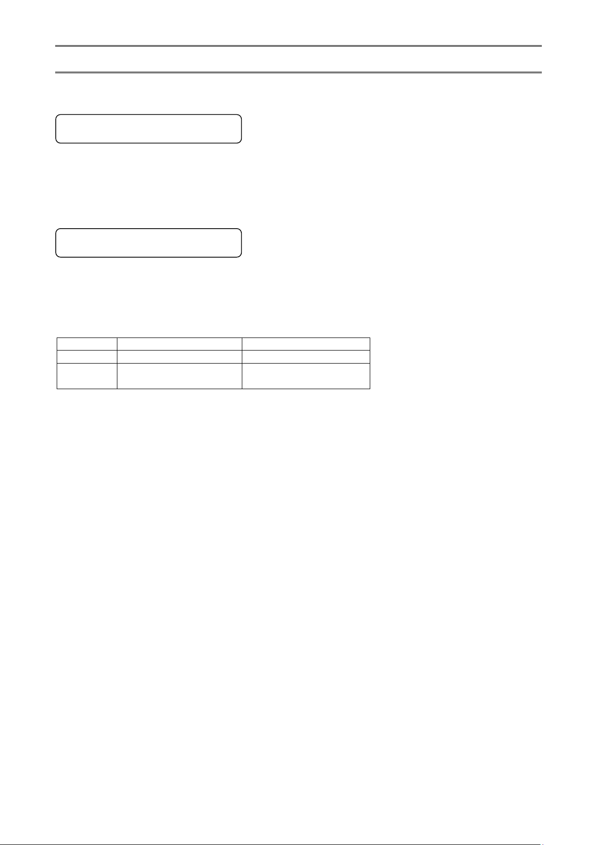
4. Communications Protocol
KL4000/KH4000
AL4000/AH4000
PRIVATE1
No communication address
No connection sequence
PRIVATE2
Communication address
available
Connection sequence
available
The unit has the following two communications protocols which can be switched using the front keys.
4-1. MODBUS Protocol
MODBUS is a registered trademark of Schneider Electric.
MODBUS protocol has RTU mode and ASCII mode which can be selected using the front keys or via communication. This
protocol provides measured data transmission, setting and operating functions.
For Ethernet interface, MODBUS protocol is implemented on TCP protocol packet to establish communication (see
section 5-3).
4-2. PRIVATE Protocol
PRIVATE is a conventionally used protocol by CHINO.
This protocol can be selected using the front keys. It provides measured data transmission, setting and operating
functions.
Two types of modes are available: PRIVATE1 and PRIVATE2, and these can be selected using the front keys.
PRIVATE1: With RS232C, data link is not necessary due to one-to-one communication with the host.
Select PRIVATE1 for RS232C.
PRIVATE2: With RS422A and RS485, data link is required.
Select PRIVATE2 for these interfaces. Also, select PRIVATE2 for RS232C when the software of the host is
shared since data link commands can be received.
The compatibility with our older models can be maintained. However, the parameters which cannot be handled by
PRIVATE are now settable by MODBUS. We recommend MODBUS protocol to customers who construct a new
communication environment.
- 4 -
Page 8

5. Communication Specifications
Communication system
:
Half-duplex start-stop synchronization
Protocol
:
MODBUS protocol
Transmission speed
:
9600, 19200, 38400bps selectable
Start bit
:
1 bit
Data length
:
7 bits (ASCII mode)
8 bits (RTU/ASCII mode)
Parity bit
:
Non (None) /Even/Odd
Stop bit
:
1 bit/2 bits
Transmission code
:
ASCII (ASCII mode)
Binary (RTU mode)
Error check
(Error detection)
:
LRC (ASCII mode)
CRC-16 (RTU mode)
Data transmission procedure
:
None
Used signals
:
Transmitted/received data only (no control signal used)
Communication system
:
Half-duplex start-stop synchronization (polling selecting
system)
Protocol
:
PRIVATE protocol
Transmission speed
:
1200, 2400, 4800, 9600bps selectable
Start bit
:
1 bit
Data length
:
7 bits/8 bits
Parity bit
:
Non (None) /Even/Odd
Stop bit
:
1 bit/2 bits
Transmission code
:
ASCII
Error check
(Error detection)
:
BCC (block check character) checksum
Data transmission procedure
:
None
Used signals
:
Transmitted/received data only (no control signal used)
Medium
:
Ethernet (10BASE-T/100BASE-TX)
Communication mode
:
Full-Duplex/Half-Duplex
Transmission speed
:
10Mbps (10BASE-T)/100Mbps (100BASE-TX)
Note that transmission speed and communication mode are
automatically recognized and cannot be set to fixed value.
Protocol
:
MODBUS (RTU) protocol on TCP/IP
Simultaneous connection
:
1 (in host communication using MODBUS protocol)
TCP/IP model layers
Main protocol used in Ethernet communication
Application layer
MODBUS
Transport layer
TCP
Internet layer
IP, ARP
Physical/data link layer
Hardware (Ethernet)
5-1. MODBUS
5-2. PRIVATE
5-3. Ethernet
Ethernet communication is supported by AL4000/AH4000 only.
The AL4000/AH4000 series provides a Web setting function on Ethernet (see section 11).
The following table shows association with TCP/IP layers in MODBUS communication.
For details of MODBUS protocol, see “8. MODBUS Protocol”.
- 5 -
Page 9

1. Establishing TCP connection
U
R
G
0
A
C
K
P
S
H
R
S
T
S
Y
N
F
I
N
0 0 0 1 0
PC
Client
Unit
Server
(1) SYN
U
R
G
0
A
C
K
P
S
H
R
S
T
S
Y
N
F
I
N
1 0 0 1 0
(2) SYN + ACK
U
R
G
0
A
C
K
P
S
H
R
S
T
S
Y
N
F
I
N
1 0 0 0 0
(3) ACK
TCP header section
TCP data section
MODBUS (RTU) protocol
TCP packet
PC
Unit
Request
Response
Request
Response
To establish communication between a PC (makes data request: client) and the unit (receives data request: server),
establish TCP connection first according to the following procedure.
(1) PC sends a TCP packet with SYN flag set to the unit.
(2) When the unit receives the SYN packet, it sends a TCP packet with SYN + ACK flag set to the PC.
(3) When the PC receives the SYN + ACK packet, it sends a TCP packet with ACK flag set to the unit.
2. Transmitting/receiving data by TCP
Once the connection has been established, various data are transmitted/received between PC (client) and the unit
(server) via MODBUS (RTU) protocol on TCP data.
- 6 -
Page 10

3. Disconnecting TCP connection
U
R
G
0
A
C
K
P
S
H
R
S
T
S
Y
N
F
I
N
0 0 0 0 1
PC
Client
Unit
Server
(1) FIN
U
R
G
0
A
C
K
P
S
H
R
S
T
S
Y
N
F
I
N
1 0 0 0 0
(2) ACK
U
R
G
0
A
C
K
P
S
H
R
S
T
S
Y
N
F
I
N
1 0 0 0 0
(4) ACK
U
R
G
0
A
C
K
P
S
H
R
S
T
S
Y
N
F
I
N
1 0 0 0 1
(3) FIN + ACK
TCP connection is disconnected with the following flow of communications.
(1) PC sends a TCP packet with FIN flag set to the unit (disconnection notice).
(2) When the unit receives the FIN packet, it sends a TCP packet with ACK flag set to the PC.
(3) The unit sends a FIN + ACK packet to the PC (disconnection notice).
(4) The PC sends an ACK packet responding to FIN to the unit.
4. Actions against communication error
When the following communication errors occur on TCP/IP, the unit takes actions described below.
● No response from the device at the other end (PC, etc.)
When the unit sends data to a communication target on Ethernet but no response (ACK) packet is returned, the
unit repeats transmission retry operation (for around three minutes maximum).
The unit disconnects TCP connection if no response is made to the transmission retry packet.
If a communication target makes a TCP connection request before the unit disconnects TCP connection, the unit
sends an RST packet to reject the request.
The unit sends an RST packet in the following situations.
When a TCP packet is received from devices other than that being connected.
When an RST packet is received from a communication target.
● Unexpected reply packet received
Generally, unexpected reply packets are ignored. However, TCP connection is disconnected immediately after
the unit receives an RST packet in situations such as when PC performs a forced disconnection of TCP
connection.
- 7 -
Page 11
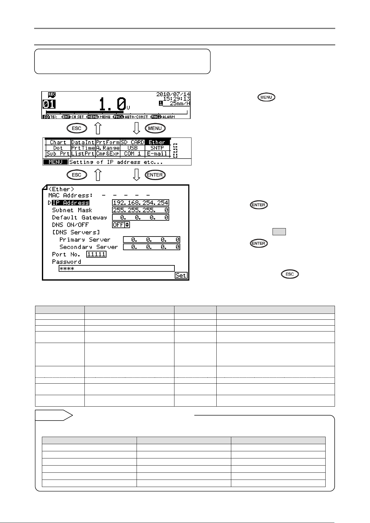
6. Communication Parameter Settings
Parameter
Function
Default
Set value
MAC Address
Ethernet MAC address of the unit
Unique value
Setting disabled
IP Address
Set IP address
192.168.254.254
**:**:**:** (each ** area is set to 0 to 255)
Subnet Mask
Set subnet mask
255.255.255.0
**:**:**:** (each ** area is set to 0 to 255)
Default Gateway
Set default gateway address of the
network used
0.0.0.0
**:**:**:** (each ** area is set to 0 to 255)
DNS ON/OFF
Select whether to use DNS (domain
name server)
OFF
OFF (not used), ON (used)
Set server like SNTP and SMTP by the name when
using DNS, or by the IP address when not using
DNS.
[DNS Servers]
Primary Server
Set primary DNS server
0.0.0.0
**:**:**:** (each ** area is set to 0 to 255)
Secondary Server
Set secondary DNS server
0.0.0.0
**:**:**:** (each ** area is set to 0 to 255)
Port No.
Set port No. for socket communication
by TCP/IP
11111
0 to 65535
Password
Set a password consisting of up to 32
characters used for setting on the Web
3571
To use the unit in a small network using a router without connecting to internal LAN or internet, set the IP address as
shown below.
Unit
IP address
Subnet mask
AH4000 A
192.168.254.254
255.255.255.0
AH4000 B
192.168.254.253
255.255.255.0
...
...
...
PC A
192.168.254.1
255.255.255.0
PC B
192.168.254.2
255.255.255.0
...
...
...
Example settings for small network
Reference
6-1. Ethernet Settings (AL4000/AH4000 Only)
(IP Address etc… Settings)
Set each parameter.
(1) Pressing the key displays the menu
window (list of setting items).
(2) Select “Ether”.
(3) Move the cursor to the parameter to be set
with the ▲/▼// keys.
(4) Press the key to make it available
for setting and then select or enter a value.
(5) After completing the settings of this item,
move the cursor to Set .
(6) Press the key to register the
settings (when chart recording is ON, a
setting change mark is printed). To cancel
the settings, press the key.
Note: Actual windows are separated. Use the ▲/▼ keys to scroll and continue settings.
[List of Ether setting parameters]
- 8 -
Page 12
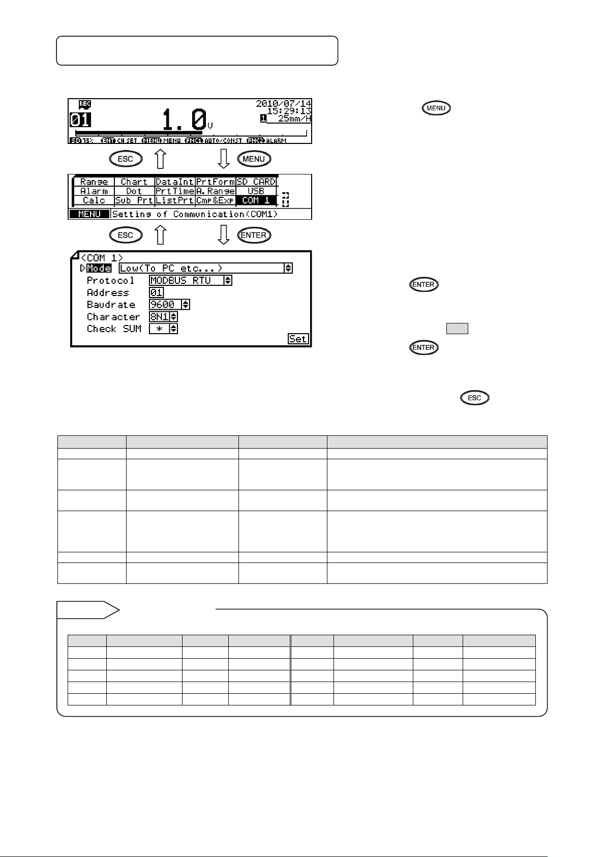
6-2. COM Settings (For AL4000/AH4000)
Parameter
Function
Default
Set value
Mode
Communication mode
Low(To PC etc…)
Fixed to Low (To PC etc…)
Protocol
Select communication
protocol
MODBUS RTU
MODBUS RTU, MODBUS ASCII, PRIVATE1 (without
connection sequence), PRIVATE2 (with connection
sequence)
Address
Set communication
address of the unit
01
01 to 99
Baudrate
Set communication speed
9600
PRIVATE: 1200, 2400, 4800, 9600bps
MODBUS: 9600, 19200, 38400bps
Changes to “9600” when changing from PRIVATE to
MODBUS or vice versa.
Character
Set transmission character
8N1
7E1, 7E2, 7O1, 7O2, 8N1, 8N2, 8E1, 8E2, 8O1, 8O2
Check SUM
Select whether to add
checksum code
*
OFF, ON
Settable only when Protocol is set to “PRIVATE”.
Note: Actual windows are separated. Use the ▲/▼ keys to
scroll and continue settings.
Codes are used to represent characters. MODBUS RTU mode can set only 8-bit characters (see section 8-1).
Code
Character length
Parity
Stop bit
Code
Character length
Parity
Stop bit
7E1
7-bit
Even
1
8N2
8-bit
Non
2
7E2
7-bit
Even
2
8E1
8-bit
Even
1
7O1
7-bit
Odd 1 8E2
8-bit
Even
2
7O2
7-bit
Odd
2
8O1
8-bit
Odd
1
8N1
8-bit
Non
1
8O2
8-bit
Odd
2
Character selection
Reference
Set each parameter.
(1) Pressing the key displays the menu
window (list of setting items).
(2) Select “COM1” or “COM2”.
(3) Move the cursor to the parameter to be set
with the ▲/▼/ / keys.
(4) Press the key to make it available
for setting and then select or enter a value.
(5) After completing the settings of this item,
move the cursor to Set .
[List of COM1 and COM2 setting parameters]
(6) Press the key to register the
settings (when chart recording is ON, a
setting change mark is printed). To cancel
the settings, press the key.
* When connecting via Ethernet, communication protocol and communication address are fixed to “MODBUS RTU” and
“01” respectively.
* Use the unit and PC at the same communication speed (use the default speed 9600bps in normal case).
* For RS422A/485, a communication address of the unit needs to be set. Make sure that one or more units connected to
a PC have unique communication address and no overlap occurs.
For RS232C, only one unit is connected, but communication address needs to be set (use the default address 01 in
normal case).
- 9 -
Page 13
Communication
specifications
Enter [ENG2 mode]
[Display mode]
Option
Go to 2. Communications
protocol
Go to 4. Communication
address
Go to 5. Communication
character
Start setting
2 sec or more
or no key operation for 1
min or more
+
2 sec or more
Go to 3. Transmission
speed
Switching between [Display mode] and [ENG1
mode] can be done by the
key instead of the
key.
Note
Substitution key
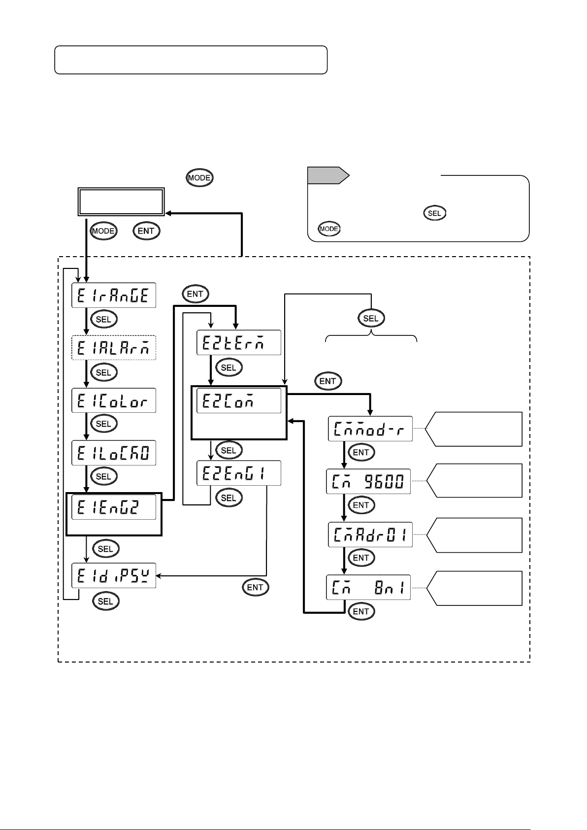
6-3. COM Settings (For KL4000/KH4000)
Communication settings are performed with [ENG2 mode] which can be entered from a [ENG1 mode] item.
The [ENG2 mode] provides items for checking remote contact specifications and setting communication parameters.
Set communication parameters according to the flow chart.
1. Checking/setting items of communication specifications
- 10 -
Page 14

2. Setting communications protocol
(4)
(5)
(6)
Communication specification items
Register
Save in the memory
and print setting
change mark
Start setting
Decimal points of all
digits flash
ON:
Flash:
Reference
Decimal
point
1) Setting range
2) Setting flow chart
<Example> Mode is changed from MODBUS RTU to MODBUS ASCII.
* Communications protocol is selected by the key in this example, but you can also use the key
to reverse.
3) Setting procedure
(MODBUS RTU mode)
(PRIVATE1: No communication address)
(MODBUS ASCII mode)
(PRIVATE2: Communication address available)
(1) Enter [ENG1 mode]
Press and hold the and keys for two seconds or more to change from [Display mode] to
[ENG1 mode].
(2) Enter [ENG2 mode]
Pressing the key changes ENG1 item. Select .
Press the key to enter [ENG2 mode].
(3) Select communication specification
Pressing the key changes ENG2 item. Select and press the key.
(4) Start communications protocol setting
Pressing the / key displays the cursor (flashing decimal point). Select .
(5) Check selection
Pressing the key flashes decimal points of all digits. If an error is found, press the /
key to reset.
(6) Register setting
When set correctly, press the key. The setting is saved in the memory and setting change mark is
printed.
(7) End
The setting window of transmission speed will be displayed. Also, the mode returns to [Display mode]
when the key is pressed and held for two seconds or more on any setting display window, or keys
are not operated for one minute or more.
- 11 -
Page 15

3. Setting transmission speed
(7)
(6)
(5)
(4)
Communication specification items
Save in the memory
and print setting
change mark
Start setting
Register
Decimal points of all
digits flash
1) Setting range
MODBUS: 9600, 19200, 38400bps
PRIVATE: 1200, 2400, 4800, 9600bps
2) Setting flow chart
<Example> Transmission speed of MODBUS protocol is changed from 9600 to 19200bps.
* Transmission speed is selected by the key in this example, but you can also use the key to
reverse.
3) Setting procedure
(1) Enter [ENG1 mode]
Press and hold the and keys for two seconds or more to change from [Display mode] to
[ENG1 mode].
(2) Enter [ENG2 mode]
Pressing the key changes ENG1 item. Select .
Press the key to enter [ENG2 mode].
(3) Select communication specification
Pressing the key changes ENG2 item. Select and press the key.
(4) Select transmission speed
Pressing the key changes communication specification item. Select (previous set
value is displayed).
(5) Start setting
Pressing the / key displays the cursor (flashing decimal point). Select .
(6) Check selection
Pressing the key flashes decimal points of all digits. If an error is found, press the /
key to reset.
(7) Register setting
When set correctly, press the key. The setting is saved in the memory and setting change mark is
printed.
(8) End
The setting window of communication address will be displayed. Also, the mode returns to [Display mode]
when the key is pressed and held for two seconds or more on any setting display window, or keys
are not operated for one minute or more.
- 12 -
Page 16
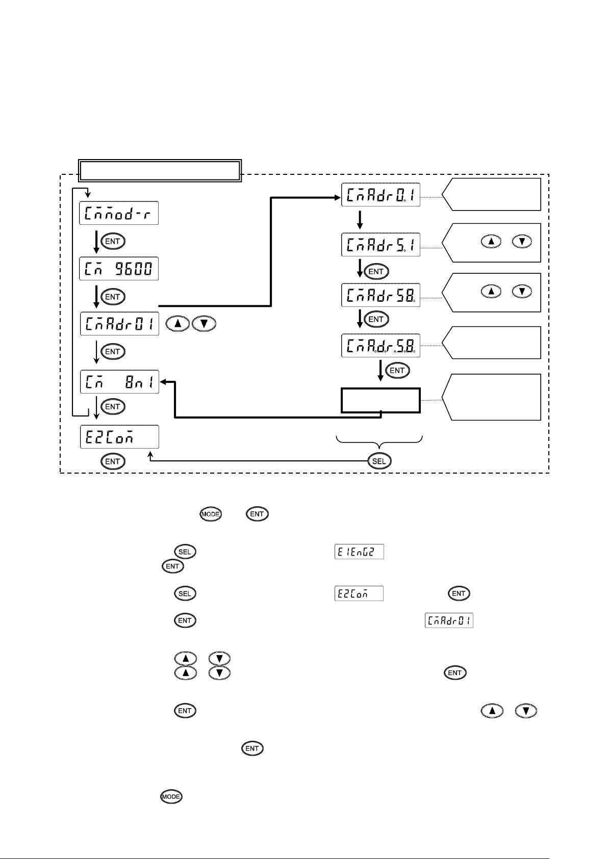
4. Setting communication address
(7)
(5)
(6)
(4)
Communication specification items
Save in the memory
and print setting
change mark
Register
Press
/
Decimal points of all
digits flash
Cursor appears on
the tens place
Start setting
Press
/
1) Setting range: 01 to 99
* For RS422A/485, a communication address of the unit needs to be set. Make sure that one or more units
connected to a PC have unique communication address and no overlap occurs. For RS232C, only one unit is
connected, but communication address needs to be set (use the default address 01 in normal case).
2) Setting flow chart <Example> Communication address is changed from 01 to 58.
3) Setting procedure
(1) Enter [ENG1 mode]
Press and hold the and keys for two seconds or more to change from [Display mode] to
[ENG1 mode].
(2) Enter [ENG2 mode]
Pressing the key changes ENG1 item. Select .
Press the key to enter [ENG2 mode].
(3) Select communication specification
Pressing the key changes ENG2 item. Select and press the key.
(4) Select communication address
Pressing the key changes communication specification item. Select (previous set
value is displayed).
(5) Start setting
Pressing the / key displays the cursor (flashing decimal point) on the tens place.
Pressing the / key increases/decreases numeric value. Press the key to move the
cursor right, and set the ones place likewise.
(6) Check set value
Pressing the key flashes decimal points of all digits. If an error is found, press the /
key to reset.
(7) Register setting
When set correctly, press the key. The setting is saved in the memory and setting change mark is
printed.
(8) End
The setting window of communication character will be displayed. Also, the mode returns to [Display mode]
when the key is pressed and held for two seconds or more on any setting display window, or keys
are not operated for one minute or more.
- 13 -
Page 17

5. Setting communication character
Display
Character length
Parity
Stop bit
7E1
7-bit
Even
1
7E2
7-bit
Even
2
7O1
7-bit
Odd
1
7O2
7-bit
Odd
2
8N1
8-bit
Non
1
8N2
8-bit
Non
2
8E1
8-bit
Even
1
8E2
8-bit
Even
2
8O1
8-bit
Odd
1
8O2
8-bit
Odd
2
(7)
(6)
(5)
(4)
Stop bit
(1: 1 bit, 2: 2 bits)
Parity
(E: EVEN, O: ODD, N: NON)
Character length
(7: 7-bit, 8: 8-bit)
Display and meaning
Reference
Communication specification items
Register
Save in the memory
and print setting
change mark
Start setting
Decimal points of all
digits flash
1) Setting range
* MODBUS RTU mode can set only 8-bit characters (see section 8-1).
2) Setting flow chart
<Example> Communication character is changed from 7E1 to 7O1.
* Communication character is selected by the key in this example, but you can also use the key
to reverse.
- 14 -
Page 18
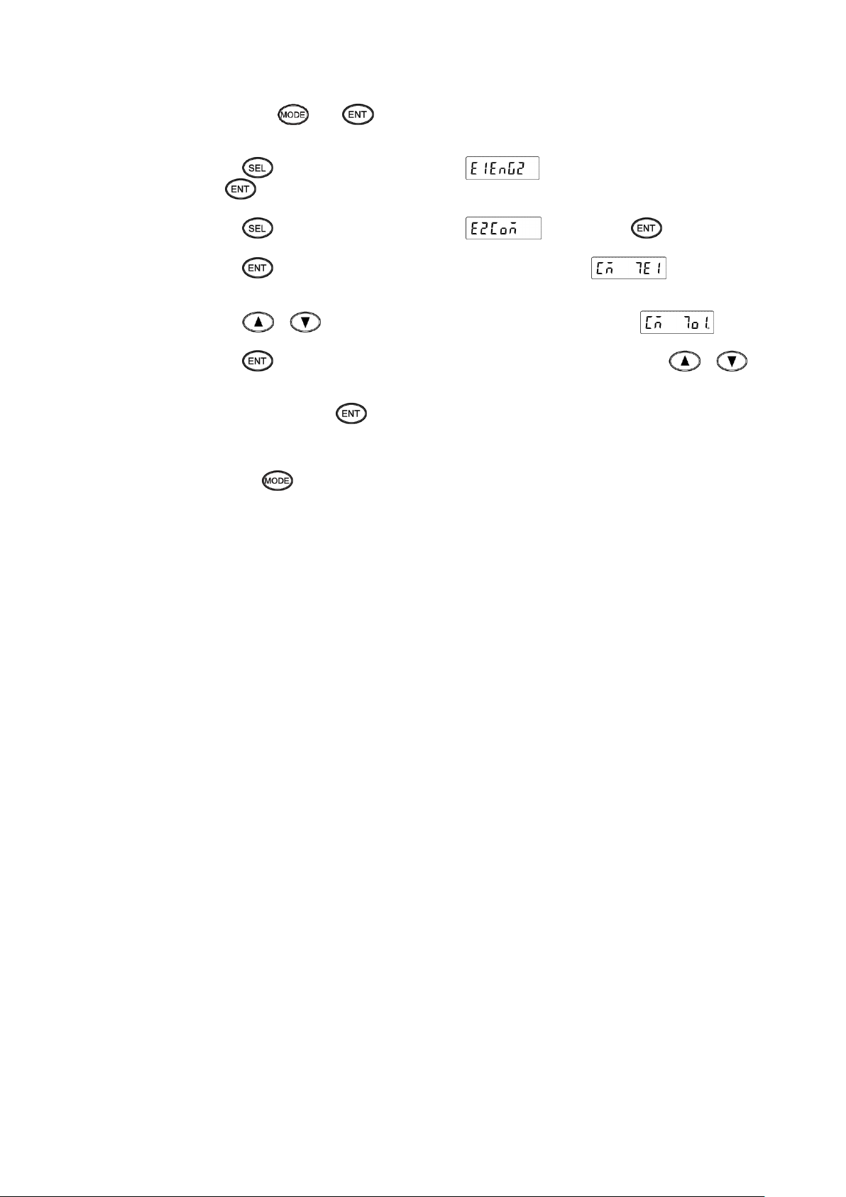
3) Setting procedure
(1) Enter [ENG1 mode]
Press and hold the and keys for two seconds or more to change from [Display mode] to
[ENG1 mode].
(2) Enter [ENG2 mode]
Pressing the key changes ENG1 item. Select .
Press the key to enter [ENG2 mode].
(3) Select communication specification
Pressing the key changes ENG2 item. Select and press the key.
(4) Select communication character
Pressing the key changes communication specification item. Select (previous set
value is displayed).
(5) Start setting
Pressing the / key displays the cursor (flashing decimal point). Select .
(6) Check selection
Pressing the key flashes decimal points of all digits. If an error is found, press the /
key to reset.
(7) Register setting
When set correctly, press the key. The setting is saved in the memory and setting change mark is
printed.
(8) End
The selection window of communication specification will be displayed. Also, the mode returns to [Display
mode] when the key is pressed and held for two seconds or more on any setting display window, or
keys are not operated for one minute or more.
- 15 -
Page 19
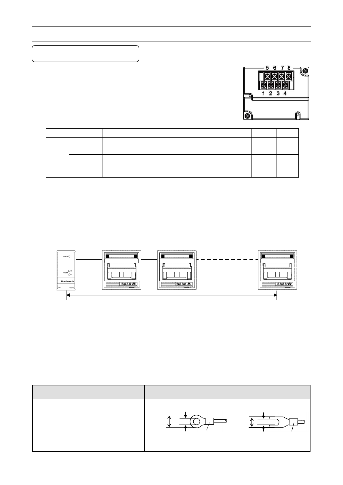
7. Wiring
1 2 3 4 5 6 7
8
COM1
RS232C
SG
SD RD
RS422A SG
SDA
SDB
RDA
RDB
RS485 SG
SA
SB
Short
with SA
Short
with SB
COM2
RS485
SA
SB
SG
Terminal board
Diameter
Tightening
torque
Termination treatment (unit: mm)
Communications
terminal
M3
0.5 N∙m
O type Y type
* O type is preferred.
Total cable length: 1.2km or less
5.2 or less
3.2 or more
t: 0.8
With an insulation sleeve
5.2 or less
3.2 or more
With an insulation sleeve
t: 0.8
7-1. Precautions on Wiring
1. Communication terminal
Terminal layout depends on the selection of communication interface.
* RS232C and RS422A/485 of COM1 are specified on purchase.
* COM2 is supported by AL4000/AH4000 only.
2. RS422A/485 communication cable extended up to 1.2km
The interval between instruments can be decided freely, however, note that the total cable length should be 1.2km or
less.
Line converter Unit
3. Take measure against noise
To avoid interference from noise, keep the communication cable separated from the power or other communication
cables, with a gap of at least 50cm between them.
4. Make sure to use crimping terminals
One of the causes of communication failure is a disconnection of cables. Make sure to install an O type or Y type
crimping terminal with insulation sleeve to the end of communication cable.
- 16 -
Page 20

5. Add termination resistor
The number of connectable units specified above is based on the use of communication
IC conforming to the communication standards. However, the number of units or
distance ensuring high quality communication varies depending on the type of
communication cable and other connected devices.
Cable
9-pin connector Crimp type ring terminals RS232C cable
Shape
Internal
wiring
Model
code
RZ-CRS6□□
Cable length: 01 to 15m (specified)
RD
SD
SG
1
2
3 4 5
6 7 8
9
RD
SD
SG
Cable for RS232C (Max. 15m)
PC side
9-pin connector
!
Caution
For RS422A/485 communications, install a 100Ω resistor to the unit which is located at the last edge of the
communication line.
(See section 7-3.2 and 7-3.3.)
6. Number of connectable units
RS232C: One unit
RS422A/485: Up to 31 units
7-2. Communication Cable
Prepare a communication cable before wiring. Dedicated cables are available from us. Contact us when you need it.
1. RS232C
Connection between PC and the unit or a line converter
- 17 -
Page 21
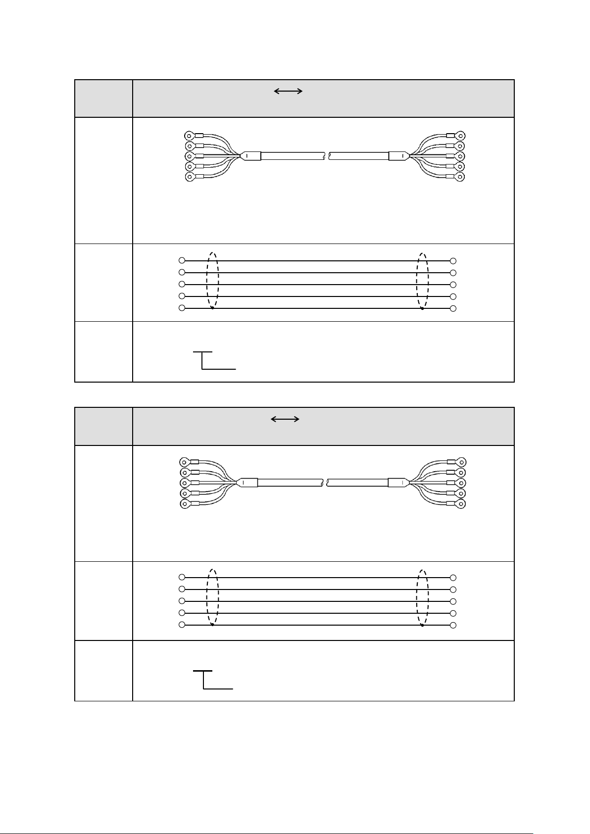
2. RS422A
Cable
Crimp type ring terminals Crimp type ring terminals RS422A cable
(for a line converter)
Shape
4-core cable of twisted 2-core cables of twisted VCTF lines. Each side has a SG
(single ground) line. Since the line converter has no SG terminal, cut and use the
cable.
Internal
wiring
Model
code
RZ-CRA2□□
Cable length: 01 to 99m (specified)
Cable
Crimp type ring terminals Crimp type ring terminals RS422A cable
(for parallel)
Shape
4-core cable of twisted 2-core cables of twisted VCTF lines. Each side has a SG
(single ground) line.
Internal
wiring
Model
code
RZ-CRA1□□
Cable length: 01 to 99m (specified)
Line converter side
Recorder side
RDB
RDA
SDA
SDB
SG
SDB
SDA
RDA
RDB
SG
SDB
SDA
RDA
RDB
SG
SDB
SDA
RDA
RDB
SG
RDA (black)
RDB (white)
SDA (red)
SDB (green)
SG (blue)
(black) SDA
(white) SDB
(red) RDA
(green) RDB
(blue) SG
Device side
Recorder side
SDA (black)
SDB (white)
RDA (red)
RDB (green)
SG (blue)
(black) SDA
(white) SDB
(red) RDA
(green) RDB
(blue) SG
Connection between a line converter and the unit
Connection between the unit and other devices
- 18 -
Page 22

3. RS485
Cable
Crimp type ring terminals Crimp type ring terminals RS485 cable
Shape
2-core cable of twisted CVVS lines. Each side has a SG (single ground) line. Since
the line converter has no SG terminal, cut and use the cable.
Internal
wiring
Model
code
RZ-LEC□□□
Cable length: 001 to 200m (specified)
SD
RD
SG
Cable for RS232C (Max.15m)
Device side
RD
SD
SG
RZ-CRS6
Communications port
PC side
RDA
RDB
SG
SA
SB
SG
Device/line converter side
Recorder side
RDA (black)
RDB (white)
SG (green)
(black) SA
(white) SB
(green) SG
Connection between the unit and other devices and between a line converter and the unit
4. Ethernet (AL4000/AH4000 only)
● Connection between PC and device
When connecting a device to a PC directly (one-to-one), use a shielded, crossover twisted pair cable
(commercially available STP cable).
● Connection between HUB and device (multiple devices can be connected)
When connecting devices to a PC via HUB (one-to-N), use a shielded, straight twisted pair cable (commercially
available STP cable).
7-3. Communication Line Wiring
1. RS232C wiring
PC and device are connected one-to-one in RS232C communication.
Example of terminal connection
- 19 -
Page 23

2. RS422A wiring
Turn the switch of
RS422A/RS485 to RS422A.
Avoid connecting SG line to FG terminal or
ground terminal of the device.
RDB
RDA
SDA
SDB
SG
終端抵抗
100Ω
Device side
Line converter
SC8-10
RDB
RDA
SDA
SDB
SD
RD
SG
1
2
3
4
5
6
7
8
Cable for RS232C (Max. 15m)
RZ-CRS6
PC side
SD
RD
SG
RDB
RDA
SDA
SDB
SG
RDB
RDA
SDA
SDB
SG
Turn the switch of RS422A/RS485
to RS485.
Avoid connecting SG line to FG terminal or
ground terminal of the device.
SA
SB
SG
終端抵抗
100Ω
Device side
Line converter
SC8-10
RDB
RDA
SD
RD
SG
1
2
3
4
5
6
7
8
Cable for RS232C (Max. 15m)
RZ-CRS6
PC side
SD
RD
SG
SA
SB
SG
SA
SB
SG
Termination
resistor
100Ω
Communications port
Communications port
Termination
resistor
100Ω
PC and multiple devices are connected in RS422A communication. A line converter is required.
RS422A cable is within 1.2km of total extension and up to 31 devices can be connected.
Install a resistor of 100Ω to the last edge of the transmission line device side.
(General metal film resistors will be fine. They are available from us, so contact us when you need it.)
Example of terminal connection
3. RS485 wiring
PC and multiple devices are connected in RS485 communication. A line converter is required.
RS485 cable is within 1.2km of total extension and up to 31 devices can be connected.
Install a resistor of 100Ω to the last edge of the transmission line device side.
(General metal film resistors will be fine. They are available from us, so contact us when you need it.)
Example of terminal connection
- 20 -
Page 24
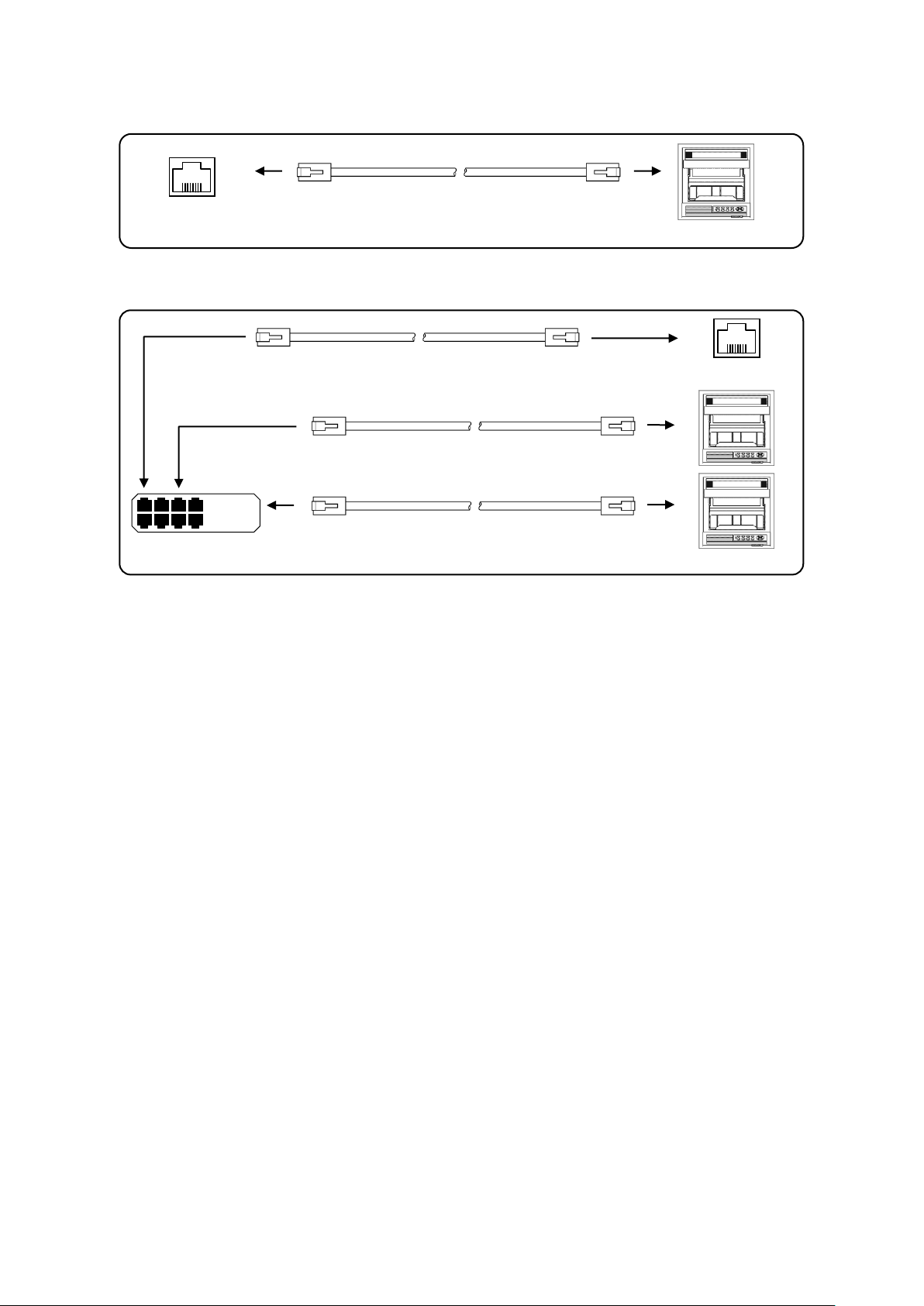
4. Ethernet wiring (AL4000/AH4000 only)
HUB
Shielded, straight twisted pair cable
(Max. 100m)
PC side
HUB
Shielded, straight twisted pair cable
(Max. 100m)
Shielded, straight twisted pair cable
(Max. 100m)
Shielded, crossover twisted pair cable
(Max. 100m)
PC side
Device side
Device side
● Example of connection between PC and Ethernet device (one-to-one connection)
● Example of connection between PC, HUB and Ethernet device (one-to-N connection)
- 21 -
Page 25

8. MODBUS Protocol
Make sure to read and understand this section to avoid any troubles.
!
Caution
1. Requesting data immediately after power-on generates an error
The unit is always ready for communications and responsive to data request from PC. However, after power-on, the
unit does not respond normally until channel data becomes ready.
For example, it takes about 20 seconds for a 24-point AH4000 recorder to have the data ready. When a data request
is received during this period, the unit returns an error.
2. Keys restricted in parameter setting (writing)
When operating the unit from PC to set parameters, etc., the / key becomes temporarily unavailable
while a setting window is displayed. The key will be available again by changing the window displayed.
3. RS232C requires communication address
Although PC and the unit are connected one-to-one in RS232C communication, a communication address needs to
be set to establish communication.
4. Be careful about command re-transmission as no control signal line is used
The serial interface of the unit makes communication without using a control line. Therefore, attention should be paid
when re-transmitting a command since reception failure may occur depending on the unit condition.
5. Do not disconnect communication cable or device, or turn ON/OFF the power
during communication
Disconnecting the cables or devices constituting the serial interface, or turning ON/OFF the devices during
communication may stop operation or generate an error. If this happens, all the devices constituting the serial
interface need to be reset to start the operation from the beginning.
6. Make sure that communication driver has been turned OFF before sending next
command
For RS422A/485 communication, multiple devices are connected in the same communication line, but only one
device whose communication address is specified by PC passes through the communication line. To send all
characters safely to PC, the communication line driver is turned OFF a few moments (about 5ms) after sending the
last character. If a PC sends a command to the next device before the driver is turned OFF, signals will interfere with
each other resulting in communication failure.
- 22 -
Page 26

Item
RTU mode
ASCII mode
Interface
RS232C, RS422A, RS485
Communication system
Half-duplex start-stop synchronization
Transmission speed
9600, 19200, 38400bps
Transmission code
Binary
ASCII
Error check
(Error detection)
Vertical
Parity
Horizontal
CRC-16
LRC
Character
configuration
Start bit
1 bit
Data length
8 bits
7 bits, 8 bits
Parity bit
None, odd, even
None*, odd, even
Stop bit
1bit/2 bits
Message start code
None
: (Colon)
Message end code
None
CR, LF
Data time interval
28-bit time or less
1 second or less
Example: RTU mode
ASCII mode
67H
36H (“6”)
89H
37H (“7”)
ABH
38H (“8”)
39H (“9”)
41H (“A”)
42H (“B”)
RTU mode
ASCII mode
Message
:
Message
CR
LF
8-1. Message Transmission Mode
Two types of message transmission mode are available: RTU (Remote Terminal Unit) mode and ASCII mode, which can
be selected using the front keys.
Comparison between RTU and ASCII modes
* For the case of 7-bit data, parity bit cannot be “None”.
1. Transmission data
The RTU mode transmits binary data. The ASCII mode divides the 8-bit binary data of RTU into high-order four bits
and low-order four bits, and turns them into characters (0 to 9, A to F).
The RTU mode enables more efficient transmission since its message is half in length compared to the ASCII mode.
2. Message frame structure
With RTU mode, the message frame consists of message section only.
With ASCII mode, the message frame consists of start character “: (colon, 3AH)”, message and end characters “CR
(carriage return, 0DH) + LF (line feed, 0AH)”.
The ASCII mode makes troubleshooting easier since it uses a message start character “:”.
- 23 -
Page 27
Slave address
Function code
Data
Error check
Code
Function
Unit
MODBUS original function
(reference)
01
Read digital (ON/OFF) settings
1 bit
Read coil status
02
Read digital input data
1 bit
Read input relay status
03
Read analog settings
16 bits
Read holding register contents
04
Read analog input data
16 bits
Read input register contents
05
Write digital setting
1 bit
Change single coil status
06
Write analog setting
16 bits
Write to single holding register
08
Send received data (for diagnosis)
Loop-back test
16
Write multiple analog settings
Write to multiple holding registers
70
Read floating data
Arbitrary command of vendors
71
Write floating data
Arbitrary command of vendors
8-2. Data Time Interval
RTU mode: 28-bit time or less (9600bps: 2.8msec, 19200bps: 1.4msec, 38400bps: 0.7msec)
ASCII mode: One second or less
When sending a message, keep the time interval between data constituting one message no longer than the time
specified above. If it is longer than the time specified above, the receiver side (the unit) recognizes that transmission of
data from the sender side is complete, and the data is handled as an abnormal message.
While the RTU mode requires continuous transmission of message characters, the ASCII mode allows for a maximum
interval of one second between characters, making it possible to use a master (PC) with a relatively slow processing
speed.
8-3. Message Structure
MODBUS message has the following structure which is applied to both RTU and ASCII modes.
1. Slave address
A slave address can be set in advance using the front keys within the range of 1 to 99. Normally, master device
communicates with a single slave device. Only a slave device whose address matches the slave address in a
command message from the master device sends a response.
The slave address “0” is used for a message addressed to all slave devices (broadcast) from the master device. In
this case, the slave devices do not send a response.
2. Function code
Function codes represent the functions to be executed by slave devices. The data is generally classified as shown in
the table below. The table also shows the comparison between MODBUS original functions and
MODBUS-compatible CHINO device functions (see section 8-9).
Function code table
- 24 -
Page 28

(1) Digital settings: Parameters mainly used to change functions such as recording ON/OFF and data printing
The data field may contain the data like input data which assigns a specific numeric
value as error data. When handling such data, perform error judgment on the data
before combining with decimal point data.
When decimal point data is combined first, error data is recognized as normal data.
Data type
Reference No.
Relative No.
MODBUS original function
(reference)
Digital settings
1 to 10000
Reference No. - 1
Coil
Digital input data
10001 to 20000
Reference No. - 10001
Input relay
Analog input data
30001 to 40000
Reference No. - 30001
Input register
Analog settings
40001 to 50000
Reference No. - 40001
Holding register
Floating data
(Floating point data)
50001 to 60000
Reference No. - 50001
!
Caution
execution.
(2) Digital input data: Event status, etc.
(3) Analog settings: Information of various settings
Within the range of 16-bit numeric values (-32768 to 32767)
(4) Analog input data: Measured data, unit specifications, etc.
Outputs a numeric value within the 16-bit range
(5) Floating data: When the data cannot be expressed by a numeric value within the 16-bit range (-32768 to
32767), floating data is used.
3. Data field
Data components depend on the function code. A master request consists of the code number of read/write target
data (a relative number obtained from reference number described in the following section) and the number of data
pieces. A slave response consists of the data responding to request.
Basic MODBUS data consists of 16-bit integers only, and the use of sign is specified for each data piece. Therefore,
real number data such as measured data is expressed by assigning the decimal point position to a separate address
to express an integer value, or by fixing the decimal point position and normalizing with the scale upper and lower
limits.
This unit employs the system of assigning the decimal point position to a separate address.
The numeric data which cannot be expressed by 16-bit integers can be read or written using floating data.
4. Reference number.
All the data handled by the unit has “reference number” assigned, and this number is required when reading/writing
data.
The data is classified into “Digital settings”, “Digital input data”, “Analog input data”, “Analog settings” and “Floating
data (floating point data)” by its type.
A “relative number” corresponding to the reference number is specified in a message.
Reference numbers and corresponding relative numbers
For example, a relative number of “Reference No. 30101 (CH1 data)” described later is “100”.
- 25 -
Page 29
Quick search table for reference No.
Data type
Parameter
Reference No
Applicable
Function code
Reference table
Digital settings
Key lock
Message printing 1
Recording ON/OFF
Feed
List printing
Title printing (message printing 2)
Data printing
Recording to SD card ON/OFF
Fast dot printing
SNTP time setting
01 to 95
01 (READ)
05 (WRITE)
See section 8-9.1
Digital input data
Remote contact status
Measured data status
Alarm status
10009 to 10480
02 (READ)
See section 8-9.2
Analog input data
Device information
Measured data
30001 to 30028
30101 to 30148
04 (READ)
See section 8-9.3
Analog settings
Channel parameters
Date and time setting
Chart speed setting
Dot printing interval setting
Periodic data printing setting
Recording format selection
Zone printing setting
Display setting
Unit-tag switch setting
Range setting
Scale setting
Burnout setting
Sensor correction setting
Recording color setting
Subtract printing setting
Unit setting
Tag setting
Alarm setting
Calculation setting
Compressed/expanded printing setting
Automatic range-shift setting
Display and recording ON/OFF setting
Communication setting
Calendar timer setting
Broken line approximation table setting
SD card setting
Measured value display order setting
Title printing (message printing 2)
Remote contact setting
Operation recording setting
Message printing 1 setting
Periodic (specified time) data printing setting
Formula setting
Data communications input setting
Fail out setting
Communication parameter setting
40001 to 44394
45001 to 45487
46501 to 46574
47001 to 47412
47906 to 47915
47931 to 47954
48001 to 48038
48069 to 48088
48101 to 48181
48202 to 48400
48501 to 48549
48601 to 48900
49001 to 49048
49101 to 49119
49902 to 49923
03 (READ)
06 (WRITE)
16 (WRITE)
See section 8-9.4
Floating data
(Floating point data)
Measured data
Data communications input
Parameters set by each channel
Range setting
Scale setting
Alarm value
Calculation setting
Compressed/expanded printing setting
Automatic range-shift setting
50101 to 50124
50201 to 50224
50301 to 51499
70 (READ)
71 (WRITE)
See section 8-9.5
- 26 -
Page 30

5. Error check
The type of error check performed on transmission frame depends on the transmission mode.
RTU mode: CRC-16
ASCII mode: LRC
1) CRC-16 calculation
In CRC system, the data to be transmitted is divided by a generating polynomial and the resulting remainder is
appended to the data. The generating polynomial is shown below.
1 + X2 + X15 + X16
Calculation is performed to the part from slave address to the end of data according to the following procedure.
(1) Initialize CRC-16 data (referred to as X) (= FFFFH)
(2) Exclusive logical sum (EX-OR) between data 1 and X → X
(3) Shift X one bit to the right → X
(4) When a carry is generated, perform EX-OR with A001H. If not, go to step (5) → X
(5) Repeat steps (3) and (4) until eight shifts have been performed.
(6) EX-OR between the next data and X → X
(7) Same as steps (3) to (5)
(8) Repeat until the last data.
(9) Create a message of the calculated 16-bit data (X). The low-order portion is followed by the high-order
portion.
Example: For [02H] [07H] data, CRC-16 value becomes 1241H therefore the error check data will be [41H] [12H].
- 27 -
Page 31

Reference: CRC-16 calculation program
/***** CRC-16 calculation program (C language) *****/
#include <stdio.h>
#include <conio.h>
void main(void)
{
/*** Internal variable declaration ***/
unsigned intiLoopCnt;/* Loop counter*/
unsigned shortusData;/* Input data*/
unsigned shortusCrcData;/* CRC-16 data*/
unsigned shortusErrChkData;/* Error check data*/
intiDummy;/* Dummy varialbe*/
/* Initialze CRC-16 output data */
usCrcData = 0xffff;
printf(“Enter hexadecimal data (exit by [q]) >¥n”);
while( scanf(“%x”,&usData) != 0 )
{
/* Perform exclusive OR between CRC output result and input data */
usCrcData = usData ^ usCrcData;
/*** Perform CRC calculation ***/
/* Repeat until 8 bits have been shifted */
for( iLoopCnt = 0 ; iLoopCnt < 8 ; iLoopCnt++ )
{
/* Check if carry is generated */
if( usCrcData & 0x0001 )
{
/* Carry generated */
/* Shift CRC output result 1 bit to the right */
usCrcData = usCrcData >> 1;
/* Perform exclusive OR with A001H */
usCrcData = usCrcData ^ 0xa001;
}
else
/* Carry not generated */
/* Shift CRC output result 1 bit to the right */
usCrcData = usCrcData >> 1;
} /* for */
} /* while */
printf( “CRC-16 data is %xH.¥n”, usCrcData );
iDummy = getch();
}
/* Create error check data */
usErrChkData = ( usCrcData >> 8) | ( usCrcData << 8 );
printf( “Error check data is %xH.”, usErrChkData );
- 28 -
Page 32

2) LRC calculation
Calculation is performed to the part from slave address to the end of data according to the following procedure.
(1) Create a message in RTU mode.
(2) Add up the data from the start (slave address) to the end → X
(3) Complement X (bit inversion) → X
(4) Add 1 (X = X + 1)
(5) Append X as LRC value to the message.
(6) Convert the whole data to ASCII characters.
Example: For [02H] [07H] data, LRC value becomes F7H therefore the binary message will be [02H] [07H]
[F7H] and the ASCII message will be [30H] [32H] [30H] [37H] [46H] [37H].
6. Precautions on data processing
(1) Since the measured data and decimal point position are assigned to separate numbers, the both pieces of
information are required at data replay.
(2) Since a single data access (change) is available, attention should be paid to the settings of related data. For
example, a change of measuring range causes the related data to be initialized.
(3) Read or write data within the range specified by reference numbers. Writing data to an undefined reference
number may affect the instrument operation.
(4) When reading consecutive reference numbers, the data of undefined reference number becomes “0”.
(5) When an error is detected while writing to consecutive reference numbers, all the settings will be invalid.
- 29 -
Page 33

Transmission mode
Number of data pieces
RTU
120
RTU (floating data)
ASCII
60
02H
[ : ]
CR
04H
00H
64H
00H
02H
94H
LRC
CR
LF
8-4. Message Creation
A message consists of (1) slave address, (2) function code, (3) data field and (4) error check code (see section 8-3).
The number of data pieces read/written at one time is as follows:
The following shows an example of creating a message.
Example: Reading “CH1” measured data of an AL4000/AH4000 unit with “slave address 02”.
1. RTU mode message
(1) Slave address: 02 [02H]
(2) Function code: 04 [04H]
The task is “Read analog input data (input register contents)”. For the case of function code “04”, specify
“relative number of data in two bytes” and “number of data pieces in two bytes” to be read in the data field (see
section 8-5, or 8-5.4 for “Function code: 04”).
* The number of data bytes needs to be checked.
(3) Data field: First relative number 100 ([00H] [64H]), number of data pieces 2 ([00H] [02H])
Measured data (analog input data) is saved through reference numbers “30001 to 40000” (see section 8-3.4).
The reference table shows that the integer part of CH1 is saved through “30101” and the decimal point position
through “30102” (see section 8-9, or 8-9.3 for “Reading measured data”).
A relative number of the first reference number “30101” is: 30101 – 30001 = 100, and it can be expressed as
[00H] [64H] by two bytes (see section 8-3.4).
The number of data pieces to be read is “two”, the integer part of CH1 and the decimal point position, which can
be expressed as [00H] [02H] by hex two bytes.
(4) Error check: CRC-16 calculation result 2730H ([30H] [27H])
Error check in RTU mode uses CRC-16 calculation (see section 8-3.5).
From steps (1) to (3), the basic part of the message is [02H] [04H] [00H] [64H] [00H] [02H], and the CRC-16
value becomes 2730H. The error check data therefore becomes [30H] [27H].
(5) Message: [02H] [04H] [00H] [64H] [00H] [02H] [30H] [27H]
Create a message according to the message structure (see section 8-3).
2. ASCII mode message
Perform LRC calculation as error check on the basic part of a message. The LRC value becomes 94H (see section
8-3.5). Convert each data piece of the basic part to ASCII code. Convert also the LRC value to ASCII code and
append it to the basic part. Add a start character “:” and end characters “CR” and “LF” to the message.
Example: 02H, 04H, 00H, 64H, 00H, 02H, 30H, 27H
[3AH] [30H] [32H] [30H] [34H] [30H] [30H] [36H] [34H]
[30H] [30H] [30H] [32H] [39H] [34H] [0DH] [0AH]
- 30 -
Page 34

Reference No.
8 9 10
11
12
13
14
15
16
17
Data
ON
Master → Device
Device → Master (normal)
Slave address
02H Slave address
02H
Function code
01H Function code
01H
Start No. (H)
00H Data count
02H
Start No. (L)
07H First 8 data bits
00H
Number of data
pieces (H)
00H Next 8 data bits
02H
Number of data
pieces (L)
0AH CRC (L)
7CH
CRC (L)
0DH CRC (H)
3DH
CRC (H)
FFH
LRC
ECH LRC
F9H
Recording
ON
0 0 0 0 0 0 0 0 0 0 0 0 0 0 1
0
First 8 data bits
15
Reference No.
8
Next 8 data bits
16
Reference No. 17
(00H)
(02H)
8-5. Function Code
Response to each function code is described below (see 8-3.2, or 8-6 for response to abnormal situation).
1. Read digital settings (read coil status)
Function code: 01 [01H]
This function reads the designated quantity of consecutive digital settings (ON/OFF) starting from the specified
number. A single data piece (one byte) contains eight ON/OFF data bits arranged in numerical order to form a
response message. LSB (D0 side) of each data piece indicates digital data of the smallest number. When the number
of readings is not a multiple of eight, unnecessary bit becomes 0.
Example: Reading 10 digital settings (reference No. 8 to 17) from slave 2
Since no reference number exists, 0 is returned.
<RTU mode>
<Error check in ASCII mode>
The error check section of CRC (L) and CRC (H) is replaced with the following.
Note: Start No. (relative number) is “reference number – 1”.
(Decimal value 7 (= 8-1) → hexadecimal value 07H)
Note: Data count means the number of data bytes.
(This is different from the required number of data pieces. In above example, the required number of data
pieces is 10, and the data count is two.)
- 31 -
Page 35

2. Read digital input data (read input relay status)
Reference No.
10109
10110
10111
10112
10113
10114
10115
10116
Data
ON
OFF
ON
OFF
Master → Device
Device → Master (normal)
Slave address
02H Slave address
02H
Function code
02H Function code
02H
Start No. (H)
00H Data count
01H
Start No. (L)
6CH First 8 data bits
05H
Number of data
pieces (H)
00H CRC (L)
61H
Number of data
pieces (L)
04H CRC (H)
CFH
CRC (L)
B9H
CRC (H)
E7H
LRC
8CH LRC
F6H
Since no reference number exists, 0
is returned.
0 0 0 0 0 1 0
1
First 8 data bits
10109
Since reference numbers 10113 to 10116
do not exist, 0 is returned.
(05H)
Reference No. 10112
Function code: 02 [02H]
This function reads the designated quantity of consecutive digital input data (ON/OFF) starting from the specified
number. A single data piece (one byte) contains eight ON/OFF data bits arranged in numerical order to form a
response message. LSB (D0 side) of each data piece indicates digital data of the smallest number. When the number
of readings is not a multiple of eight, unnecessary bit becomes 0.
Start No. (relative number) is “reference number – 10001”.
Example: Reading four digital input settings (reference No. 10109 to 10112) from slave 2
Level 1 Level 2 Level 3 Level 4
CH1 event
<RTU mode>
status
<Error check in ASCII mode>
The error check section of CRC (L) and CRC (H) is replaced with the following.
Note: Start No. (relative number) is “reference number – 10001”.
(Decimal value 108 (= 10109-10001) → hexadecimal value 6CH)
Note: Data count means the number of data bytes.
(This is different from the required number of data pieces. In above example, the required number of data
pieces is four, and the data count is one.)
- 32 -
Page 36

3. Read analog settings (read holding register contents)
Reference No.
40104
40105
40106
Data
0
(0000H)
1000
(03E8H)
1
(0001H)
Master → Device
Device → Master (normal)
Slave address
02H Slave address
02H
Function code
03H Function code
03H
Start No. (H)
00H Data count
06H
Start No. (L)
67H Lower limit data (H)
00H
Number of data
pieces (H)
00H Lower limit data (L)
00H
Number of data
pieces (L)
03H Upper limit data (H)
03H
CRC (L)
B4H Upper limit data (L)
E8H
CRC (H)
27H Decimal point data
(H)
00H
Decimal point data
(L)
01H
CRC (L)
74H
CRC (H)
35H
LRC
91H LRC
09H
← Data example for 0.0 to 100.0
Function code: 03 [03H]
This function reads the designated quantity of consecutive analog settings (two bytes: 16 bits) starting from the
specified number. The data is divided into high-order eight bits and low-order eight bits, and then arranged in
numerical order to form a response message.
Start No. (relative number) is “reference number – 40001”.
Example: Reading CH1 range upper/lower limits and decimal point from slave 2
(Reading three analog settings (reference No. 40104 to 40106) from slave 2)
<RTU mode>
<Error check in ASCII mode>
Note: Start No. (relative number) is “reference number – 40001”.
(Decimal value 103 (= 40104-40001) → hexadecimal value 67H)
Note: Data count means the number of data bytes.
(This is different from the required number of data pieces. In above example, the required number of data
pieces is three, and the data count is six.)
Note: The number of data pieces in a message which can be received (transmitted by the unit) at one time is limited
(see section 8-4).
4. Read analog input data (read input register contents)
Function code: 04 [04H]
This function reads the designated quantity of consecutive analog input data (two bytes: 16 bits) starting from the
specified number. The data is divided into high-order eight bits and low-order eight bits, and then arranged in
numerical order to form a response message.
A response example is the same as “Function code 03”, though the Start No. (relative number) becomes “reference
number – 30001”.
- 33 -
Page 37

5. Write digital setting (change single coil status)
Master → Device
Device → Master (normal)
Slave address
02H Slave address
02H
Function code
05H Function code
05H
Setting No. (H)
00H Setting No. (H)
00H
Setting No. (L)
13H Setting No. (L)
13H
Setting status (H)
FFH Setting status (H)
FFH
Setting status (L)
00H Setting status (L)
00H
CRC (L)
7DH CRC (L)
7DH
CRC (H)
CCH CRC (H)
CCH
LRC
E7H LRC
E7H
Function code: 05 [05H]
This function makes the digital setting of specified number the specified status (ON/OFF).
Example: Executing message printing on slave 2
(Setting the digital setting (reference No. 20) of slave 2 to ON)
<RTU mode>
<Error check in ASCII mode>
Note: Normal response is the same as command message.
Note: Setting No. (relative number) is “reference number – 1”.
(Decimal value 19 (= 20-1) → hexadecimal value 13H)
Note: Set “FF00H” to execute.
For the case of key lock and recording ON/OFF, set “0000H” to turn OFF or “FF00H” to turn ON.
Note: When the slave address is set to 0, all the slave devices execute the command, but no response is made from
any of them.
- 34 -
Page 38

6. Write analog settings (write to single holding register)
Master → Device
Device → Master (normal)
Slave address
02H Slave address
02H
Function code
06H Function code
06H
Setting No. (H)
00H Setting No. (H)
00H
Setting No. (L)
6EH Setting No. (L)
6EH
Setting status (H)
00H Setting status (H)
00H
Setting status (L)
14H Setting status (L)
14H
CRC (L)
E8H CRC (L)
E8H
CRC (H)
2BH CRC (H)
2BH
LRC
76H LRC
76H
Master → Device
Device → Master (normal)
Slave address
02H Slave address
02H
Function code
08H Function code
08H
Diagnosis code (H)
Fixed
00H
Diagnosis code (H)
Fixed
00H
Diagnosis code (L)
00H
Diagnosis code (L)
00H
Arbitrary data
* Received arbitrary
data
*
Arbitrary data
* Received arbitrary
data
*
CRC (L)
* CRC (L)
*
CRC (H)
* CRC (H)
*
LRC
*
LRC
*
Function code: 06 [06H]
This function changes the analog setting of specified number to the specified value.
Example: Setting CH1 sensor correction value of slave 2 to 20
(Setting the analog setting (reference No. 40111) of slave 2 to “20”)
<RTU mode>
<Error check in ASCII mode>
Note: Normal response is the same as command message.
Note: Setting No. (relative number) is “reference number – 40001”.
(Decimal value 110 (= 40111-40001) → hexadecimal value 6EH)
Note: When the slave address is set to 0, all the slave devices execute the command, but no response is made from
any of them.
7. Loop-back test
Function code: 08 [08H]
Transmission between master and slave is checked, and a response is made according to the specified diagnosis
code.
The unit performs “return check” which transmits unaltered received data, and the diagnosis code is fixed to “0000H”.
Example: Performing a loop-back test on slave 2
<RTU mode>
<Error check in ASCII mode>
- 35 -
Page 39

8. Write multiple analog settings (write to multiple holding registers)
Reference No.
40104
40105
40106
Data
0
(0000H)
1000
(03E8H)
1
(0001H)
Master → Device
Device → Master (normal)
Slave address
02H Slave address
02H
Function code
10H Function code
10H
Start No. (H)
00H Start No. (H)
00H
Start No. (L)
67H Start No. (L)
67H
Number of data
pieces (H)
00H Number of data
pieces (H)
00H
Number of data
pieces (L)
03H Number of data
pieces (L)
03H
Data count
06H CRC (L)
31H
1st data (H)
00H CRC (H)
E4H
1st data (L)
00H
2nd data (H)
03H
2nd data (L)
E8H
3rd data (H)
00H
3rd data (L)
01H
CRC (L)
10H
CRC (H)
97H
LRC
92H LRC
84H
Function code: 16 [10H]
This function changes the designated quantity of analog settings starting from the specified number to the specified
value. The data is divided into high-order eight bits and low-order eight bits, and arranged in numerical order to
transmit.
Example: Setting CH1 range upper/lower limits and decimal point of slave 2 to “0.0 to 100.0”
(Setting three analog settings (reference No. 40104 to 40106) of slave 2)
<RTU mode>
<Error check in ASCII mode>
Note: Start No. (relative number) is “reference number – 40001”.
(Decimal value 103 (= 40104-40001) → hexadecimal value 67H)
Note: When the slave address is set to 0, all the slave devices execute the command, but no response is made from
any of them.
Note: The number of data pieces in a message which can be transmitted (received by the unit) at one time is limited
(see section 8-4).
- 36 -
Page 40

9. Write floating data
Reference No.
50201
50202
Data
1234.5
(44H,9AH,50H,00H)
1.2345
(3FH,9FH,6FH,D2H)
Master → Device
Device → Master (normal)
Slave address
01H Slave address
01H
Function code
47H Function code
47H
Data type
00H Data type
00H
Start No. (H)
00H Start No. (H)
00H
Start No. (L)
C8H Start No. (L)
C8H
Number of data
pieces (H)
00H Number of data
pieces (H)
00H
Number of data
pieces (L)
02H Number of data
pieces (L)
02H
Data count
08H CRC (L)
04H
First data (1)
00H CRC (H)
88H
First data (2)
50H
First data (3)
9AH
First data (4)
44H
Next data (1)
D2H
Next data (2)
6FH
Next data (3)
9FH
Next data (4)
3FH
CRC (L)
C1H
CRC (H)
B3H
LRC
99H LRC
EEH
Function code: 71 [47H]
This function changes the designated quantity of floating data (floating point data) starting from the specified number
to the specified value. The standard MODBUS does not have this function code. A single piece of floating point data
is represented by four bytes (32 bits).
Example: Writing data of CH1 and CH2 used for data communications input on slave 1
(Setting two pieces of floating data (reference No. 50201 and 50202) of slave 1)
<RTU mode>
<Error check in ASCII mode>
Note: Data type is fixed to 00H.
Note: Start No. (relative number) is “reference number – 50001”.
(Decimal value 200 (= 50201-50001) → hexadecimal value C8H)
Note: Data count means the number of data bytes.
(This is different from the number of parameters. In above example, the number of parameters is two, and the
data count is eight.)
Note: Transmit the floating point data from LSB.
- 37 -
Page 41

10. Read floating data
S
E
M
31
30 23
22 0
Reference No.
50101
50102
Data
1234.5
(44H,9AH,50H,00H)
1.2345
(3FH,9FH,6FH,D2H)
Master → Device
Device → Master (normal)
Slave address
01H Slave address
01H
Function code
46H Function code
46H
Data type
00H Data type
00H
Start No. (H)
00H Data count
08H
Start No. (L)
64H First data (1)
00H
Number of data
pieces (H)
00H First data (2)
50H
Number of data
pieces (L)
02H First data (3)
9AH
CRC (L)
C5H First data (4)
44H
CRC (H)
78H Next data (1)
D2H
Next data (2)
6FH
Next data (3)
9FH
Next data (4)
3FH
CRC (L)
28H
CRC (H)
3DH
LRC
53H LRC
64H
Function code: 70 [46H]
This function reads the designated quantity of floating data (floating point data) starting from the specified number.
The standard MODBUS does not have this function code. A single piece of floating point data is represented by four
bytes (32 bits).
The floating data format conforms to IEEE754.
S: Sign bit of fixed-point part
E: Exponential part (8 bits)
M: Fixed-point part (23 bits)
Value = (-1)S x 1.M x 2
Example: Reading CH1 and CH2 floating data of slave 1
(Reading two pieces of floating data (reference No. 50101 and 50102) of slave 1)
<RTU mode>
E-127
<Error check in ASCII mode>
Note: Data type is fixed to 00H.
Note: Start No. (relative number) is “reference number – 50001”.
(Decimal value 100 (= 50101-50001) → hexadecimal value 64H)
Note: Data count means the number of data bytes.
(This is different from the required number of data pieces. In above example, the required number of data
pieces is two, and the data count is eight.)
Note: Transmit the floating point data from LSB.
- 38 -
Page 42

Slave address
Function code
Error code
Function code + 80H
01
81H
Error code
02
82H
CRC (L)
03
83H
CRC (H)
04
84H
05
85H
06
86H
08
88H
16
90H
70
C6H
71
C7H
8-6. Response to Abnormal Situation
When a message from the master device contains an error, the following responses will be made.
1. No response
Message is ignored and no response is made in the following situations.
(1) A transmission error (overrun, framing, parity, CRC or LRC) is detected in a message.
(2) A slave address in a message does not match the receiver address.
(3) Data interval in a message is too long.
RTU mode: More than 28-bit time
ASCII mode: More than one second
(4) Transmission parameters do not agree.
(5) A received message exceeds 512 bytes.
Note: When the slave address is “0” for writing functions, message is executed if it contains no error, but no response
is made.
2. Returning error message
When a message from the master device does not contain an error described in 8-6.1, but any of the following
problems occur, a code indicating the error will be returned as “error message”.
The format of error message is shown below.
* Error code is formed by adding 80H to a function code.
Example: When the function code is 16, the error code becomes 10H (16) + 80H = 90H.
- 39 -
Page 43

Error codes are shown in the following table.
Error code
Description
01H
Function code error
Undefined function code is received.
02H
Relative number (reference number) error
Undefined start number or setting number is received.
03H
Error in number of data pieces
Any of the following cases:
(1) Received function code disagrees with the number of data pieces.
● “Data count” is not twice the “Number of data pieces” when the function code is
“16”
● “Data count” is not quadruple the “Number of data pieces” when the function code
is “71”
● “Data count” disagrees with “Received data count” when the function code is “16”
or “71”
(2) Transmission data in response to a received message exceeds the specified number
of data pieces.
● RTU: Up to 120 (up to 60 for floating data)
● ASCII: Up to 60
11H
Out-of-range setting (setting error)
Any of the following cases:
(1) Undefined range No.
(2) Setting (binary) exceeds the specified range
(3) Decimal point data is out of the range of “0 to 3”
(4) RJ internal is set for a case other than thermocouple input range
(5) Burnout is set to other than None for the voltage (V) input range
12H
Setting disabled
When a setting message is received in any of the following situations:
● Parameter setting for multiple channels is required when performing parameter setting
on each channel
● Parameter setting of unused optional function is required
(A “0” response is transmitted for a read message.)
● Setting on the unit or via Web window is in progress
● Setting contents are being registered
(Registration process, which takes about one second, starts three seconds after
receiving the last frame of setting.)
● Setting is performed on an item which is not available for setting during recording
- 40 -
Page 44

KH4000/AH4000
KL4000/AL4000
Number of printed
characters
Max. 72
Max. 40
Character type
Alphanumeric characters (upper/lower cases), symbols and katakana
(When using katakana, 8-bit data must be used for communication.)
Color
Selectable from six colors: red, black, blue, green, brown and purple
Feed specification
Specify whether to perform printing by interrupting trace printing, or perform printing on
trace printing
8-7. Title Printing (Message Printing 2) Function
Arbitrary characters can be printed on the chart of the unit through communications.
<Printing specifications>
<Procedure>
(1) The master device transmits the information of color, feed specification and printing contents to the unit.
(See reference numbers: 48001 to 48038.)
(2) The master device transmits an execution message to the unit.
(See reference number 20 and section 8-5.5.)
Note: When step (2) is executed without taking step (1), the previously printed contents will be printed again.
Nothing will be printed if message printing has never been executed.
8-8. Data Communications Input
Using this function, the “data” transmitted from the master device through communication is recorded in the same manner
as measured data. For the transmitted data, operations including recording, calculation (for alarm etc.) and
communication output are performed just like measured data.
<Procedure>
(1) The master device transmits a calculation number and recording range (upper/lower limits) of the channel for
recording data communications input in advance to the unit. Once these items have been transmitted, there is no
need of transmitting them again until a change of recording range, etc. becomes necessary. In this case, the range
and scale settings become invalid and the above recording range becomes effective for recording (see reference
numbers: 40165 to 42500).
(2) The master device transmits the data to be recorded.
(Reference numbers: 49001 to 49048, or 50201 to 50224 for floating data)
(3) The data is updated every time transmission from the master device occurs.
Note: After the power is turned on, recording data is invalid (display: “- - - -“) until the first data is transmitted from the
master device.
Note: Even if the range is set for the channel to be recorded, measured data is replaced with the input data through
communications.
- 41 R/W ∙∙∙ R: READ, W: WRITE
Page 45

Reference
No.
Applicable
function code
R/W
Description
Details
01
01
05
R
W
Key lock
0 (0000h) = UNLOCK (key lock disabled)
1 (FF00h) = LOCK (key lock enabled)
The value in () is for the case of function code 05.
Error code: 01H, 02H, 03H, 11H, 12H
10
01
05
R
W
Message printing 1 (1)
execute
* AL4000/AH4000 only
0 (0000h) = Not executed (finished)
1 (FF00h) = Executing (started)
The value in () is for the case of function code 05.
Error code: 01H, 02H, 03H, 11H, 12H
11
01
05
R
W
Message printing 1 (2)
execute
* AL4000/AH4000 only
0 (0000h) = Not executed (finished)
1 (FF00h) = Executing (started)
The value in () is for the case of function code 05.
Error code: 01H, 02H, 03H, 11H, 12H
12
01
05
R
W
Message printing 1 (3)
execute
* AL4000/AH4000 only
0 (0000h) = Not executed (finished)
1 (FF00h) = Executing (started)
The value in () is for the case of function code 05.
Error code: 01H, 02H, 03H, 11H, 12H
13
01
05
R
W
Message printing 1 (4)
execute
* AL4000/AH4000 only
0 (0000h) = Not executed (finished)
1 (FF00h) = Executing (started)
The value in () is for the case of function code 05.
Error code: 01H, 02H, 03H, 11H, 12H
14
01
05
R
W
Message printing 1 (5)
execute
* AL4000/AH4000 only
0 (0000h) = Not executed (finished)
1 (FF00h) = Executing (started)
The value in () is for the case of function code 05.
Error code: 01H, 02H, 03H, 11H, 12H
15
01
05
R
W
Message printing 1 (6)
execute
* AL4000/AH4000 only
0 (0000h) = Not executed (finished)
1 (FF00h) = Executing (started)
The value in () is for the case of function code 05.
Error code: 01H, 02H, 03H, 11H, 12H
16
01
05
R
W
Message printing 1 (7)
execute
* AL4000/AH4000 only
0 (0000h) = Not executed (finished)
1 (FF00h) = Executing (started)
The value in () is for the case of function code 05.
Error code: 01H, 02H, 03H, 11H, 12H
17
01
05
R
W
Recording ON/OFF
0 (0000h) = Recording OFF
1 (FF00h) = Recording ON
The value in () is for the case of function code 05.
Error code: 01H, 02H, 03H, 11H, 12H
18
01
05
R
W
Feed execute
0 (0000h) = Not executed (finished)
1 (FF00h) = Executing (started)
The value in () is for the case of function code 05.
Error code: 01H, 02H, 03H, 11H, 12H
19
01
05
R
W
List printing 1 execute
0 (0000h) = Not executed (finished)
1 (FF00h) = Executing (started)
The value in () is for the case of function code 05.
Error code: 01H, 02H, 03H, 11H, 12H
20
01
05
R
W
Title printing execute
(Message printing 2
execute)
0 (0000h) = Not executed (finished)
1 (FF00h) = Executing (started)
The value in () is for the case of function code 05.
Error code: 01H, 02H, 03H, 11H, 12H
8-9. Reference Table
1. Digital parameters
- 42 R/W ∙∙∙ R: READ, W: WRITE
Page 46

Reference
No.
Applicable
function code
R/W
Description
Details
21
01
05
R
W
Data printing execute
0 (0000h) = Not executed (finished)
1 (FF00h) = Executing (started)
The value in () is for the case of function code 05.
Error code: 01H, 02H, 03H, 11H, 12H
22
01
05
R
W
Recording to SD card
ON/OFF
* AL4000/AH4000 only
0 (0000h) = Recording OFF
1 (FF00h) = Recording ON
The value in () is for the case of function code 05.
Error code: 01H, 02H, 03H, 11H, 12H
26
01
05
R W Fast dot printing
* AL4000/AH4000 only
0 (0000h) = Standard (approx. 5sec/point)
1 (FF00h) = Fast (approx. 2.5sec/point)
The value in () is for the case of function code 05.
Error code: 01H, 02H, 03H, 11H, 12H
33
01
05
R
W
List printing 1 execute
0 (0000h) = Not executed (finished)
1 (FF00h) = Executing (started)
The value in () is for the case of function code 05.
Error code: 01H, 02H, 03H, 11H, 12H
34
01
05
R
W
List printing 2 execute
0 (0000h) = Not executed (finished)
1 (FF00h) = Executing (started)
The value in () is for the case of function code 05.
Error code: 01H, 02H, 03H, 11H, 12H
35
01
05
R
W
List printing 3 execute
0 (0000h) = Not executed (finished)
1 (FF00h) = Executing (started)
The value in () is for the case of function code 05.
Error code: 01H, 02H, 03H, 11H, 12H
61
01
05
R
W
Message printing 1 (8)
execute
* AL4000/AH4000 only
0 (0000h) = Not executed (finished)
1 (FF00h) = Executing (started)
The value in () is for the case of function code 05.
Error code: 01H, 02H, 03H, 11H, 12H
62
01
05
R
W
Message printing 1 (9)
execute
* AL4000/AH4000 only
0 (0000h) = Not executed (finished)
1 (FF00h) = Executing (started)
The value in () is for the case of function code 05.
Error code: 01H, 02H, 03H, 11H, 12H
63
01
05
R
W
Message printing 1 (10)
execute
* AL4000/AH4000 only
0 (0000h) = Not executed (finished)
1 (FF00h) = Executing (started)
The value in () is for the case of function code 05.
Error code: 01H, 02H, 03H, 11H, 12H
64
01
05
R
W
Message printing 1 (11)
execute
* AL4000/AH4000 only
0 (0000h) = Not executed (finished)
1 (FF00h) = Executing (started)
The value in () is for the case of function code 05.
Error code: 01H, 02H, 03H, 11H, 12H
65
01
05
R
W
Message printing 1 (12)
execute
* AL4000/AH4000 only
0 (0000h) = Not executed (finished)
1 (FF00h) = Executing (started)
The value in () is for the case of function code 05.
Error code: 01H, 02H, 03H, 11H, 12H
66
01
05
R
W
Message printing 1 (13)
execute
* AL4000/AH4000 only
0 (0000h) = Not executed (finished)
1 (FF00h) = Executing (started)
The value in () is for the case of function code 05.
Error code: 01H, 02H, 03H, 11H, 12H
67
01
05
R
W
Message printing 1 (14)
execute
* AL4000/AH4000 only
0 (0000h) = Not executed (finished)
1 (FF00h) = Executing (started)
The value in () is for the case of function code 05.
Error code: 01H, 02H, 03H, 11H, 12H
- 43 R/W ∙∙∙ R: READ, W: WRITE
Page 47

Reference
No.
Applicable
function code
R/W
Description
Details
68
01
05
R
W
Message printing 1 (15)
execute
* AL4000/AH4000 only
0 (0000h) = Not executed (finished)
1 (FF00h) = Executing (started)
The value in () is for the case of function code 05.
Error code: 01H, 02H, 03H, 11H, 12H
69
01
05
R
W
Message printing 1 (16)
execute
* AL4000/AH4000 only
0 (0000h) = Not executed (finished)
1 (FF00h) = Executing (started)
The value in () is for the case of function code 05.
Error code: 01H, 02H, 03H, 11H, 12H
70
01
05
R
W
Message printing 1 (17)
execute
* AL4000/AH4000 only
0 (0000h) = Not executed (finished)
1 (FF00h) = Executing (started)
The value in () is for the case of function code 05.
Error code: 01H, 02H, 03H, 11H, 12H
71
01
05
R
W
Message printing 1 (18)
execute
* AL4000/AH4000 only
0 (0000h) = Not executed (finished)
1 (FF00h) = Executing (started)
The value in () is for the case of function code 05.
Error code: 01H, 02H, 03H, 11H, 12H
72
01
05
R
W
Message printing 1 (19)
execute
* AL4000/AH4000 only
0 (0000h) = Not executed (finished)
1 (FF00h) = Executing (started)
The value in () is for the case of function code 05.
Error code: 01H, 02H, 03H, 11H, 12H
73
01
05
R
W
Message printing 1 (20)
execute
* AL4000/AH4000 only
0 (0000h) = Not executed (finished)
1 (FF00h) = Executing (started)
The value in () is for the case of function code 05.
Error code: 01H, 02H, 03H, 11H, 12H
95
01
05
R
W
SNTP time setting
execute
* AL4000/AH4000 only
0 (0000h) = Not executed (finished)
1 (FF00h) = Executing (started)
The value in () is for the case of function code 05.
Error code: 01H, 02H, 03H, 11H, 12H
- 44 -
Page 48

2. Digital input data
R/W ∙∙∙ R: READ
Reference
No.
Applicable
function code
R/W
Description
Details
10009
10010
10011
10012
10013
10014
10015
10016
10017
10018
10019
10020
10021
10022
10023
10024
10025
10026
10027
10028
02
R
Remote contact 1 status
Remote contact 2 status
Remote contact 3 status
Remote contact 4 status
Remote contact 5 status
Remote contact 6 status
Remote contact 7 status
Remote contact 8 status
Remote contact 9 status
Remote contact 10 status
Remote contact 11 status
Remote contact 12 status
Remote contact 13 status
Remote contact 14 status
Remote contact 15 status
Remote contact 16 status
Remote contact 17 status
Remote contact 18 status
Remote contact 19 status
Remote contact 20 status
Remote contact input status
0: OFF
1: ON
10101
10102
02
R
CH1 status 1
Status represented by 2 bits
00: Measured value
01: Calculation data
10: Communication input data
Error code: 01H, 02H, 03H
10105
10106
10107
10108
02
R
CH1 status 2
Status represented by 4 bits
0000: Normal data
0001: + Over range
0010: - Over range
0100: Burnout
1000: Invalid data (initialization or data collection in
progress, or range not set)
Error code: 01H, 02H, 03H
10109
10110
10111
10112
02
R
CH1 alarm level 1
CH1 alarm level 2
CH1 alarm level 3
CH1 alarm level 4
Activation status
0: Alarm not activated
1: Alarm activated
Error code: 01H, 02H, 03H
10117
10118
02
R
CH2 status 1
Same as CH1
10121
to
10124
02
R
CH2 status 2
Same as CH1
10125
to
10128
02
R
CH2 alarm level
1 to 4 activation status
Same as CH1
10133
10134
02
R
CH3 status 1
Same as CH1
10137
to
10140
02
R
CH3 status 2
Same as CH1
- 45 R/W ∙∙∙ R: READ
Page 49

Reference
No.
Applicable
function code
R/W
Description
Details
10141
to
10144
02
R
CH3 alarm level
1 to 4 activation status
Same as CH1
10149
10150
02
R
CH4 status 1
Same as CH1
10153
to
10156
02
R
CH4 status 2
Same as CH1
10157
to
10160
02
R
CH4 alarm level
1 to 4 activation status
Same as CH1
10165
10166
02
R
CH5 status 1
Same as CH1
10169
to
10172
02
R
CH5 status 2
Same as CH1
10173
to
10177
02
R
CH5 alarm level
1 to 4 activation status
Same as CH1
10181
10182
02
R
CH6 status 1
Same as CH1
10185
to
10188
02
R
CH6 status 2
Same as CH1
10189
to
10192
02
R
CH6 alarm level
1 to 4 activation status
Same as CH1
10197
10198
02
R
CH7 status 1
Same as CH1
10201
to
10204
02
R
CH7 status 2
Same as CH1
10205
to
10208
02
R
CH7 alarm level
1 to 4 activation status
Same as CH1
10213
10214
02
R
CH8 status 1
Same as CH1
10217
to
10220
02
R
CH8 status 2
Same as CH1
10221
to
10224
02
R
CH8 alarm level
1 to 4 activation status
Same as CH1
10229
10230
02
R
CH9 status 1
Same as CH1
10233
to
10236
02
R
CH9 status 2
Same as CH1
10237
to
10240
02
R
CH9 alarm level
1 to 4 activation status
Same as CH1
10245
10246
02
R
CH10 status 1
Same as CH1
- 46 R/W ∙∙∙ R: READ
Page 50

Reference
No.
Applicable
function code
R/W
Description
Details
10249
to
10252
02
R
CH10 status 2
Same as CH1
10253
to
10256
02
R
CH10 alarm level
1 to 4 activation status
Same as CH1
10261
10262
02
R
CH11 status 1
Same as CH1
10265
to
10268
02
R
CH11 status 2
Same as CH1
10269
to
10272
02
R
CH11 alarm level
1 to 4 activation status
Same as CH1
10277
10278
02
R
CH12 status 1
Same as CH1
10281
to
10284
02
R
CH12 status 2
Same as CH1
10285
to
10288
02
R
CH12 alarm level
1 to 4 activation status
Same as CH1
10293
10294
02
R
CH13 status 1
Same as CH1
10297
to
10300
02
R
CH13 status 2
Same as CH1
10301
to
10304
02
R
CH13 alarm level
1 to 4 activation status
Same as CH1
10309
10310
02
R
CH14 status 1
Same as CH1
10313
to
10316
02
R
CH14 status 2
Same as CH1
10317
to
10320
02
R
CH14 alarm level
1 to 4 activation status
Same as CH1
10325
10326
02
R
CH15 status 1
Same as CH1
10329
to
10332
02
R
CH15 status 2
Same as CH1
10333
to
10336
02
R
CH15 alarm level
1 to 4 activation status
Same as CH1
10341
10342
02
R
CH16 status 1
Same as CH1
10345
to
10348
02
R
CH16 status 2
Same as CH1
- 47 R/W ∙∙∙ R: READ
Page 51

Reference
No.
Applicable
function code
R/W
Description
Details
10349
to
10352
02
R
CH16 alarm level
1 to 4 activation status
Same as CH1
10357
10358
02
R
CH17 status 1
Same as CH1
10361
to
10364
02
R
CH17 status 2
Same as CH1
10365
to
10368
02
R
CH17 alarm level
1 to 4 activation status
Same as CH1
10373
10374
02
R
CH18 status 1
Same as CH1
10377
to
10380
02
R
CH18 status 2
Same as CH1
10381
to
10384
02
R
CH18 alarm level
1 to 4 activation status
Same as CH1
10389
10390
02
R
CH19 status 1
Same as CH1
10393
to
10396
02
R
CH19 status 2
Same as CH1
10397
to
10400
02
R
CH19 alarm level
1 to 4 activation status
Same as CH1
10405
10406
02
R
CH20 status 1
Same as CH1
10409
to
10412
02
R
CH20 status 2
Same as CH1
10413
to
10416
02
R
CH20 alarm level
1 to 4 activation status
Same as CH1
10421
10422
02
R
CH21 status 1
Same as CH1
10425
to
10428
02
R
CH21 status 2
Same as CH1
10429
to
10432
02
R
CH21 alarm level
1 to 4 activation status
Same as CH1
10437
10438
02
R
CH22 status 1
Same as CH1
10441
to
10444
02
R
CH22 status 2
Same as CH1
10445
to
10448
02
R
CH22 alarm level
1 to 4 activation status
Same as CH1
10453
10454
02
R
CH23 status 1
Same as CH1
- 48 R/W ∙∙∙ R: READ
Page 52

Reference
No.
Applicable
function code
R/W
Description
Details
10457
to
10460
02
R
CH23 status 2
Same as CH1
10461
to
10464
02
R
CH23 alarm level
1 to 4 activation status
Same as CH1
10469
10470
02
R
CH24 status 1
Same as CH1
10473
to
10476
02
R
CH24 status 2
Same as CH1
10477
to
10480
02
R
CH24 alarm level
1 to 4 activation status
Same as CH1
- 49 -
Page 53

3. Analog input data
R/W ∙∙∙ R: READ
Reference
No.
Applicable
function code
R/W
Description
Details
30001
04
R
Device name character
1, 2
ASCII “AL”/“AH”/”BL”/”BH” (type)
Error code: 01H, 02H, 03H, 12H
30002
04
R
Device name character
3, 4
ASCII “41”/“42”/“45”/“46”/“47”
Error code: 01H, 02H, 03H, 12H
30003
04
R
Device name character
5, 6
ASCII: Input points
“06”: 6 points
“12”: 12 points
“24”: 24 points
Error code: 01H, 02H, 03H, 12H
30004
04
R
Device name character
7, 8
ASCII 1st digit: Communication type
“N”: None
“E”: Ethernet
“R”: COM1_RS232C
“A”: COM1_RS422A/485
“Q”: COM1_RS232C + COM2_RS485
“C”: COM1_RS422A/485 + COM2_RS485
“G”: COM1_RS422A/485 +
COM2_RS485 + Ethernet
ASCII 2nd digit: Alarm output + remote contact
“0”: None
“2”: 2 points of mechanical relay „a‟ contact output
“4”: 4 points of mechanical relay „c‟ contact output + 5
points of remote contact input
“A”: 6 points of mechanical relay „a‟ contact output + 5
points of remote contact input
“8”: 8 points of mechanical relay „c‟ contact output +
10 points of remote contact input
“B”: 12 points of mechanical relay „a‟ contact output +
10 points of remote contact input
“F”: 16 points of mechanical relay „c‟ contact output +
20 points of remote contact input
“D”: 24 points of mechanical relay „a‟ contact output +
20 points of remote contact input
Error code: 01H, 02H, 03H, 12H
30005
04
R
Device name character
9, 10
ASCII 1st digit: Power supply
“A”: 100 to 240V AC
“D”: 24V AC/24V DC
ASCII 2nd digit: 1st digit of OP/SP code
Depends on the specifications
Error code: 01H, 02H, 03H, 12H
30006
04
R
Device name character
11, 12
ASCII 1st digit: 2nd digit of OP/SP code
Depends on the specifications
ASCII 2nd digit: 3rd digit of OP/SP code
Depends on the specifications
Error code: 01H, 02H, 03H, 12H
30009
04
R
ROM version
(Application CPU)
ASCII 2 digits
Error code: 01H, 02H, 03H, 12H
30010
04
R
ROM version
(Printer CPU)
ASCII 2 digits
Error code: 01H, 02H, 03H, 12H
1) Reading device information
- 50 -
Page 54

R/W ∙∙∙ R: READ
Reference
No.
Applicable
function code
R/W
Description
Details
30011
04
R
ROM version
(Preamplifier 1)
ASCII 2 digits
Error code: 01H, 02H, 03H, 12H
30012
04
R
ROM version
(Preamplifier 2)
ASCII 2 digits
Error code: 01H, 02H, 03H, 12H
30017
04
R
Input points
Number of channels
Error code: 01H, 02H, 03H, 12H
30025
04
R
Alarm output points
0: None, 2: 2 points, 4: 4 points, 6: 6 points, 8: 8 points,
12: 12 points, 16: 16 points, 24: 24 points
Error code: 01H, 02H, 03H, 12H
30026
04
R
Remote contact input
points
0: None, 5: 5 points, 10: 10 points, 20: 20 points
Error code: 01H, 02H, 03H, 12H
30027
04
R
Communication type
0: None
1: COM1_RS232C
2: COM1_RS422A/485
3: COM1_RS232C + COM2_RS485
4: COM1_RS422A/485 + COM2_RS485
5: COM1_RS422A/485 +
COM2_RS485 + Ethernet
6: Ethernet
Error code: 01H, 02H, 03H, 12H
30028
04
R
Option information
0: None
Error code: 01H, 02H, 03H, 12H
R/W ∙∙∙ R: READ
Reference
No.
Applicable
function code
R/W
Description
Details
30101
04
R
CH1 data
DATA: -30000 to 30000
32767: + Over range
-32767: - Over range
32766: Burnout
-32766: Invalid data
32764: Calculation error
Error code: 01H, 02H, 03H, 12H
30102
04
R
CH1 decimal point
0 to 3
Error code: 01H, 02H, 03H, 12H
30103
04
R
CH2 data
Same as CH1
30104
04
R
CH2 decimal point
Same as CH1
30105
04
R
CH3 data
Same as CH1
30106
04
R
CH3 decimal point
Same as CH1
30107
04
R
CH4 data
Same as CH1
30108
04
R
CH4 decimal point
Same as CH1
30109
04
R
CH5 data
Same as CH1
30110
04
R
CH5 decimal point
Same as CH1
30111
04
R
CH6 data
Same as CH1
30112
04
R
CH6 decimal point
Same as CH1
30113
04
R
CH7 data
Same as CH1
30114
04
R
CH7 decimal point
Same as CH1
30115
04
R
CH8 data
Same as CH1
30116
04
R
CH8 decimal point
Same as CH1
30117
04
R
CH9 data
Same as CH1
30118
04
R
CH9 decimal point
Same as CH1
2) Reading measured data
- 51 R/W ∙∙∙ R: READ
Page 55

Reference
No.
Applicable
function code
R/W
Description
Details
30119
04
R
CH10 data
Same as CH1
30120
04
R
CH10 decimal point
Same as CH1
30121
04
R
CH11 data
Same as CH1
30122
04
R
CH11 decimal point
Same as CH1
30123
04
R
CH12 data
Same as CH1
30124
04
R
CH12 decimal point
Same as CH1
30125
04
R
CH13 data
Same as CH1
30126
04
R
CH13 decimal point
Same as CH1
30127
04
R
CH14 data
Same as CH1
30128
04
R
CH14 decimal point
Same as CH1
30129
04
R
CH15 data
Same as CH1
30130
04
R
CH15 decimal point
Same as CH1
30131
04
R
CH16 data
Same as CH1
30132
04
R
CH16 decimal point
Same as CH1
30133
04
R
CH17 data
Same as CH1
30134
04
R
CH17 decimal point
Same as CH1
30135
04
R
CH18 data
Same as CH1
30136
04
R
CH18 decimal point
Same as CH1
30137
04
R
CH19 data
Same as CH1
30138
04
R
CH19 decimal point
Same as CH1
30139
04
R
CH20 data
Same as CH1
30140
04
R
CH20 decimal point
Same as CH1
30141
04
R
CH21 data
Same as CH1
30142
04
R
CH21 decimal point
Same as CH1
30143
04
R
CH22 data
Same as CH1
30144
04
R
CH22 decimal point
Same as CH1
30145
04
R
CH23 data
Same as CH1
30146
04
R
CH23 decimal point
Same as CH1
30147
04
R
CH24 data
Same as CH1
30148
04
R
CH24 decimal point
Same as CH1
0
AZI 0 0
EV4
EV3
EV2
EV1
ERR
BURN
OF
UF
DP
* About status information
MSB (15) (11) (7) (4) LSB (0)
AZI : Wind data 0 (Normal data)/1 (Wind data)
EV1 to EV4 : Each alarm status 0 (Not activated)/1 (Activated)
ERR : Input status 0 (Normal)/1 (Abnormal)
BURN : Sensor disconnection 0 (Not occurred)/1 (Occurred)
OF : Over range 0 (Not occurred)/1 (Occurred)
UF : Under range 0 (Not occurred)/1 (Occurred)
DP : Decimal point position of data|0|0|0|0|: 0, |0|0|0|1|: 1, |0|0|1|0|: 2, |0|0|1|1|: 3
- 52 -
Page 56

4. Analog parameters
R/W ∙∙∙ R: READ, W: WRITE
Reference
No.
Applicable
function code
R/W
Description
Details
40001
03
06
16
R
W
W
Date and time setting
(year)
ASCII 2 digits (1st digit can use space code)
00 to 99: 2000 to 2099
Error code: 01H, 02H, 03H, 12H
40002
03
06
16
R
W
W
Date and time setting
(month)
ASCII 2 digits (1st digit can use space code)
01 to 12
Error code: 01H, 02H, 03H, 12H
40003
03
06
16
R
W
W
Date and time setting
(day)
ASCII 2 digits (1st digit can use space code)
01 to 31
Error code: 01H, 02H, 03H, 12H
40004
03
06
16
R
W
W
Date and time setting
(hour)
ASCII 2 digits (1st digit can use space code)
00 to 23
Error code: 01H, 02H, 03H, 12H
40005
03
06
16
R
W
W
Date and time setting
(minute)
ASCII 2 digits (1st digit can use space code)
00 to 59
Error code: 01H, 02H, 03H, 12H
40006
03
06
16
R
W
W
Date and time setting
(second)
ASCII 2 digits (1st digit can use space code)
00 to 59
Error code: 01H, 02H, 03H, 12H
40007
03
R
First 2 digits of year
ASCII 2 digits
Fixed to “20”
Error code: 01H, 02H, 03H, 12H
40008
03
R
Last 2 digits of year
ASCII 2 digits
00 to 99
Error code: 01H, 02H, 03H, 12H
40011
03
06
16
R
W
W
DipSW1
High-order 16 bits
Bit31 to Bit16
Error code: 01H, 02H, 03H, 12H
40012
03
06
16
R
W
W
DipSW1
Low-order 16 bits
Bit15 to Bit0
Error code: 01H, 02H, 03H, 12H
40017
03
R
Executing chart
Speed number
1 to 3
Only reading enabled
Error code: 01H, 02H, 03H, 12H
40018
03
06
16
R
W
W
Dot printing interval
* AL4000/AH4000 only
0: 5sec, 1: 2.5sec, 2: Linked to chart speed
Error code: 01H, 02H, 03H, 12H
40019
03
06
16
R
W
W
Chart
Speed 1
1 to 1500 [mm/H]
-125: 12.5 [mm/H]
Error code: 01H, 02H, 03H, 12H
40022
03
06
16
R
W
W
Chart
Speed 2
1 to 1500 [mm/H]
-125: 12.5 [mm/H]
Error code: 01H, 02H, 03H, 12H
40025
03
06
16
R
W
W
Chart
Speed 3
1 to 1500 [mm/H]
-125: 12.5 [mm/H]
Error code: 01H, 02H, 03H, 12H
40034
03
06
16
R
W
W
Data interval
Interval (hour)
ASCII 2 digits (1st digit can use space code)
00 to 24
Error code: 01H, 02H, 03H, 12H
40035
03
06
16
R
W
W
Data interval
Interval (minute)
ASCII 2 digits (1st digit can use space code)
00 to 59
Error code: 01H, 02H, 03H, 12H
1) Parameters common to channels (1)
- 53 R/W ∙∙∙ R: READ, W: WRITE
Page 57

Reference
No.
Applicable
function code
R/W
Description
Details
40036
03
06
16
R
W
W
Data interval
Start time (hour)
ASCII 2 digits (1st digit can use space code)
00 to 23
Error code: 01H, 02H, 03H, 12H
40037
03
06
16
R
W
W
Data interval
Start time (minute)
ASCII 2 digits (1st digit can use space code)
00 to 59
Error code: 01H, 02H, 03H, 12H
40049
03
06
16
R
W
W
Recording format type
* AL4000/AH4000 only
0: Standard, 1: Automatic range-shift (normal), 2:
Compressed/expanded printing, 3: Zone printing, 4:
Automatic range-shift (Overlap)
Error code: 01H, 02H, 03H, 12H
40050
03
06
16
R
W
W
Zone printing
Number of areas
* AL4000/AH4000 only
2 (AL4000)
2 to 4 (AH4000)
Error code: 01H, 02H, 03H, 12H
40051
03
06
16
R
W
W
Zone printing
1st area CH1
* AL4000/AH4000 only
ASCII 2 digits (1st digit can use space code)
01 to the number of channels, 00H: No setting
Error code: 01H, 02H, 03H, 12H
40052
03
06
16
R
W
W
Zone printing
1st area division 1
* AL4000/AH4000 only
0: No setting, 1: /, 2: Error code: 01H, 02H, 03H, 12H
40053
03
06
16
R
W
W
Zone printing
1st area CH2
* AL4000/AH4000 only
ASCII 2 digits (1st digit can use space code)
01 to the number of channels, 00H: No setting
Error code: 01H, 02H, 03H, 12H
40054
03
06
16
R
W
W
Zone printing
1st area division 2
* AL4000/AH4000 only
0: No setting, 1: /, 2: Error code: 01H, 02H, 03H, 12H
40055
03
06
16
R
W
W
Zone printing
1st area CH3
* AL4000/AH4000 only
ASCII 2 digits (1st digit can use space code)
01 to the number of channels, 00H: No setting
Error code: 01H, 02H, 03H, 12H
40056
03
06
16
R
W
W
Zone printing
2nd area CH1
* AL4000/AH4000 only
ASCII 2 digits (1st digit can use space code)
01 to the number of channels, 00H: No setting
Error code: 01H, 02H, 03H, 12H
40057
03
06
16
R
W
W
Zone printing
2nd area division 1
* AL4000/AH4000 only
0: No setting, 1: /, 2: Error code: 01H, 02H, 03H, 12H
40058
03
06
16
R
W
W
Zone printing
2nd area CH2
* AL4000/AH4000 only
ASCII 2 digits (1st digit can use space code)
01 to the number of channels, 00H: No setting
Error code: 01H, 02H, 03H, 12H
40059
03
06
16
R
W
W
Zone printing
2nd area division 2
* AL4000/AH4000 only
0: No setting, 1: /, 2: Error code: 01H, 02H, 03H, 12H
40060
03
06
16
R
W
W
Zone printing
2nd area CH3
* AL4000/AH4000 only
ASCII 2 digits (1st digit can use space code)
01 to the number of channels, 00H: No setting
Error code: 01H, 02H, 03H, 12H
40061
03
06
16
R
W
W
Zone printing
3rd area CH1
* AL4000/AH4000 only
ASCII 2 digits (1st digit can use space code)
01 to the number of channels, 00H: No setting
Error code: 01H, 02H, 03H, 12H
40062
03
06
16
R
W
W
Zone printing
3rd area division 1
* AL4000/AH4000 only
0: No setting, 1: /, 2: Error code: 01H, 02H, 03H, 12H
40063
03
06
16
R
W
W
Zone printing
3rd area CH2
* AL4000/AH4000 only
ASCII 2 digits (1st digit can use space code)
01 to the number of channels, 00H: No setting
Error code: 01H, 02H, 03H, 12H
- 54 R/W ∙∙∙ R: READ, W: WRITE
Page 58

Reference
No.
Applicable
function code
R/W
Description
Details
40064
03
06
16
R
W
W
Zone printing
3rd area division 2
* AL4000/AH4000 only
0: No setting, 1: /, 2: Error code: 01H, 02H, 03H, 12H
40065
03
06
16
R
W
W
Zone printing
3rd area CH3
* AL4000/AH4000 only
ASCII 2 digits (1st digit can use space code)
01 to the number of channels, 00H: No setting
Error code: 01H, 02H, 03H, 12H
40066
03
06
16
R
W
W
Zone printing
4th area CH1
* AL4000/AH4000 only
ASCII 2 digits (1st digit can use space code)
01 to the number of channels, 00H: No setting
Error code: 01H, 02H, 03H, 12H
40067
03
06
16
R
W
W
Zone printing
4th area division 1
* AL4000/AH4000 only
0: No setting, 1: /, 2: Error code: 01H, 02H, 03H, 12H
40068
03
06
16
R
W
W
Zone printing
4th area CH2
* AL4000/AH4000 only
ASCII 2 digits (1st digit can use space code)
01 to the number of channels, 00H: No setting
Error code: 01H, 02H, 03H, 12H
40069
03
06
16
R
W
W
Zone printing
4th area division 2
* AL4000/AH4000 only
0: No setting, 1: /, 2: Error code: 01H, 02H, 03H, 12H
40070
03
06
16
R
W
W
Zone printing
4th area CH3
* AL4000/AH4000 only
ASCII 2 digits (1st digit can use space code)
01 to the number of channels, 00H: No setting
Error code: 01H, 02H, 03H, 12H
40090
03
06
16
R
W
W
Display mode
* AL4000/AH4000 only
1: 1CH, 2: 1CH + Bar, 3: 6CH, 4: 12CH, 5: 24CH
Error code: 01H, 02H, 03H, 12H
40091
03
06
16
R
W
W
Unit-tag switching
* AL4000/AH4000 only
0: Unit, 1: Tag
Error code: 01H, 02H, 03H, 12H
40092
03
06
16
R
W
W
Display CH
Manual-auto switching
* AL4000/AH4000 only
0: Manual, 1: Automatic
Error code: 01H, 02H, 03H, 12H
40093
03
06
16
R
W
W
CH update interval
* AL4000/AH4000 only
0: Linked to dot printing, 1: 1sec, 2: 2sec, 3: 3sec, 4:
5sec, 5: 10sec, 6: 30sec
Error code: 01H, 02H, 03H, 12H
40094
03
06
16
R
W
W
LCD backlight
* AL4000/AH4000 only
0: Always ON, 1: Automatic
Error code: 01H, 02H, 03H, 12H
40095
03
06
16
R
W
W
LCD backlight
Brightness
* AL4000/AH4000 only
1 (dark) to 5 (light)
Error code: 01H, 02H, 03H, 12H
40096
03
06
16
R
W
W
Chart illumination
ON/OFF
* AL4000/AH4000 only
0: Always ON, 1: OFF, 2: Automatic
Error code: 01H, 02H, 03H, 12H
40097
03
06
16
R
W
W
Chart illumination
Brightness
* AL4000/AH4000 only
0: OFF
1 (dark) to 5 (light)
Error code: 01H, 02H, 03H, 12H
40098
03
06
16
R
W
W
Display order setting
ON/OFF
* AL4000/AH4000 only
0: OFF, 1: ON
Error code: 01H, 02H, 03H, 12H
- 55 R/W ∙∙∙ R: READ, W: WRITE
Page 59

Reference
No.
Applicable
function code
R/W
Description
Details
40102
03
06
16
R
W W CH1 range No.
ASCII 2 digits (1st digit can use space code)
00H: No setting
Error code: 01H, 02H, 03H, 11H, 12H
40103
03
06
16
R
W
W
CH1 RJ
internal/external
0: External, 1: Internal
(Fixed to External except for thermocouple input)
Error code: 01H, 02H, 03H, 11H, 12H
40104
03
06
16
R
W W CH1 range lower limit
-30000 to 30000
(Up to 9 digits including upper and lower limits and
signs)
Error code: 01H, 02H, 03H, 11H, 12H
40105
03
06
16
R
W W CH1 range upper limit
-30000 to 30000
(Up to 9 digits including upper and lower limits and
signs)
Error code: 01H, 02H, 03H, 11H, 12H
40106
03
06
16
R
W
W
CH1 range decimal
point
Decimal point position of the range0 to 3
(Both range upper and lower limits use the same
decimal point position.)
Error code: 01H, 02H, 03H, 11H, 12H
40107
03
06
16
R
W W CH1 scale lower limit
-30000 to 30000
Error code: 01H, 02H, 03H, 11H, 12H
40108
03
06
16
R
W W CH1 scale upper limit
-30000 to 30000
Error code: 01H, 02H, 03H, 11H, 12H
40109
03
06
16
R
W
W
CH1 scale
Decimal point position
Decimal point position of the scale0 to 3
(Both scale upper and lower limits use the same
decimal point position.)
Error code: 01H, 02H, 03H, 11H, 12H
40110
03
06
16
R
W W CH1 burnout
0: None, 1: Up burnout, 2: Down burnout
Error code: 01H, 02H, 03H, 11H, 12H
40111
03
06
16
R
W
W
CH1 sensor correction
(Offset)
-30000 to 30000(Decimal point position of scale is
used.)
Error code: 01H, 02H, 03H, 11H, 12H
40112
03
06
16
R
W W CH1 recording color
1: Red, 2: Black, 3: Blue, 4: Green, 5: Brown, 6: Purple
Error code: 01H, 02H, 03H, 11H, 12H
40113
03
06
16
R
W
W
CH1 subtract printing
Reference CH
ASCII 2 digits (1st digit can use space code)
01 to the number of channels, 00H: No setting
40114
03
06
16
R
W
W
CH1 subtract printing
Subtraction CH
ASCII 2 digits (1st digit can use space code)
01 to the number of channels, 00H: No setting
40115
03
06
16
R
W
W
CH1 subtract printing
reference value
-30000 to 30000 (Decimal point position of scale of
reference CH is used.)
* This is enabled when subtraction CH is not set.
Error code: 01H, 02H, 03H, 11H, 12H
40116
03
06
16
R
W
W
CH1 subtract printing
range
Lower limit
-30000 to 30000 (Decimal point position of recording
range is used.)
Error code: 01H, 02H, 03H, 11H, 12H
2) Programming parameters per channel
Note: Writing multiple parameters across two or more channels will constitute an error (error code: 12H).
- 56 R/W ∙∙∙ R: READ, W: WRITE
Page 60

Reference
No.
Applicable
function code
R/W
Description
Details
40117
03
06
16
R
W
W
CH1 subtract printing
range
Upper limit
-30000 to 30000 (Decimal point position of recording
range is used.)
Error code: 01H, 02H, 03H, 11H, 12H
40119
03
06
16
R
W W CH1 unit character 1, 2
ASCII 2 digits
00H: No setting
Error code: 01H, 02H, 03H, 11H, 12H
40120
03
06
16
R
W W CH1 unit character 3, 4
ASCII 2 digits
00H: No setting
Error code: 01H, 02H, 03H, 11H, 12H
40121
03
06
16
R
W W CH1 unit character 5, 6
ASCII 2 digits
00H: No setting
Error code: 01H, 02H, 03H, 11H, 12H
40125
03
06
16
R
W W CH1 tag character 1, 2
ASCII 2 digits
00H: No setting
Error code: 01H, 02H, 03H, 11H, 12H
40126
03
06
16
R
W W CH1 tag character 3, 4
ASCII 2 digits
00H: No setting
Error code: 01H, 02H, 03H, 11H, 12H
40127
03
06
16
R
W W CH1 tag character 5, 6
ASCII 2 digits
00H: No setting
Error code: 01H, 02H, 03H, 11H, 12H
40128
03
06
16
R
W W CH1 tag character 7, 8
ASCII 2 digits
00H: No setting
Error code: 01H, 02H, 03H, 11H, 12H
40129
03
06
16
R
W W CH1 tag character 9, 10
ASCII 2 digits
00H: No setting
Error code: 01H, 02H, 03H, 11H, 12H
40131
03
06
16
R
W W Integration reset
1: Reset integration
Error code: 01H, 02H, 03H, 11H, 12H
40133
03
06
16
R
W
W
CH1 level 1
Alarm type
0: None, 1: H, 2: L, 3: U, 4: D, 5: B, 6: S
Error code: 01H, 02H, 03H, 11H, 12H
40134
03
06
16
R
W
W
CH1 level 1
Alarm value
-30000 to 30000 (Decimal point position of scale is
used.)
Error code: 01H, 02H, 03H, 11H, 12H
40135
03
06
16
R
W
W
CH1 level 1
Alarm output relay No.
ASCII 2 digits (1st digit can use space code)
01 to the number of alarm outputs
00H: No setting, 99: Dummy output
Error code: 01H, 02H, 03H, 11H, 12H
40136
03
06
16
R
W
W
CH1 level 1
Alarm output mode
0: OR, 1: AND
Error code: 01H, 02H, 03H, 11H, 12H
40137
03
06
16
R
W
W
CH1 level 1
Alarm reference CH
ASCII 2 digits (1st digit can use space code)
01 to the number of channels, 00H: No setting
* This is enabled when differential alarm is used.
Error code: 01H, 02H, 03H, 11H, 12H
40138
03
06
16
R
W
W
CH1 level 1
Alarm reference time
1 to 6000
* This is enabled when rate-of-change alarm is used.
Error code: 01H, 02H, 03H, 11H, 12H
40139
03
06
16
R
W
W
CH1 level 1
Alarm deadband
0 to 30000 (Decimal point position of scale is used.)
Error code: 01H, 02H, 03H, 11H, 12H
- 57 R/W ∙∙∙ R: READ, W: WRITE
Page 61

Reference
No.
Applicable
function code
R/W
Description
Details
40140
03
06
16
R
W
W
CH1 level 1
Alarm delay
0 to 6000 [sec]
Error code: 01H, 02H, 03H, 11H, 12H
40141
03
06
16
R
W
W
CH1 level 2
Alarm type
0: None, 1: H, 2: L, 3: U, 4: D, 5: B, 6: S
Error code: 01H, 02H, 03H, 11H, 12H
40142
03
06
16
R
W
W
CH1 level 2
Alarm value
-30000 to 30000(Decimal point position of scale is
used.)
Error code: 01H, 02H, 03H, 11H, 12H
40143
03
06
16
R
W
W
CH1 level 2
Alarm output relay No.
ASCII 2 digits (1st digit can use space code)
01 to the number of alarm outputs
00H: No setting, 99: Dummy output
Error code: 01H, 02H, 03H, 11H, 12H
40144
03
06
16
R
W
W
CH1 level 2
Alarm output mode
0: OR, 1: AND
Error code: 01H, 02H, 03H, 11H, 12H
40145
03
06
16
R
W
W
CH1 level 2
Alarm reference CH
ASCII 2 digits (1st digit can use space code)
01 to the number of channels, 00H: No setting
* This is enabled when differential alarm is used.
Error code: 01H, 02H, 03H, 11H, 12H
40146
03
06
16
R
W
W
CH1 level 2
Alarm reference time
1 to 6000
* This is enabled when rate-of-change alarm is used.
Error code: 01H, 02H, 03H, 11H, 12H
40147
03
06
16
R
W
W
CH1 level 2
Alarm deadband
0 to 30000 (Decimal point position of scale is used.)
Error code: 01H, 02H, 03H, 11H, 12H
40148
03
06
16
R
W
W
CH1 level 2
Alarm delay
0 to 6000 [sec]
Error code: 01H, 02H, 03H, 11H, 12H
40149
03
06
16
R
W
W
CH1 level 3
Alarm type
* AL4000/AH4000 only
0: None, 1: H, 2: L, 3: U, 4: D, 5: B, 6: S
Error code: 01H, 02H, 03H, 11H, 12H
40150
03
06
16
R
W
W
CH1 level 3
Alarm value
* AL4000/AH4000 only
-30000 to 30000 (Decimal point position of scale is
used.)
Error code: 01H, 02H, 03H, 11H, 12H
40151
03
06
16
R
W
W
CH1 level 3
Alarm output relay No.
* AL4000/AH4000 only
ASCII 2 digits (1st digit can use space code)
01 to the number of alarm outputs
00H: No setting, 99: Dummy output
Error code: 01H, 02H, 03H, 11H, 12H
40152
03
06
16
R
W
W
CH1 level 3
Alarm output mode
* AL4000/AH4000 only
0: OR, 1: AND
Error code: 01H, 02H, 03H, 11H, 12H
40153
03
06
16
R
W
W
CH1 level 3
Alarm reference CH
* AL4000/AH4000 only
ASCII 2 digits (1st digit can use space code)
01 to the number of channels, 00H: No setting
* This is enabled when differential alarm is used.
Error code: 01H, 02H, 03H, 11H, 12H
40154
03
06
16
R
W
W
CH1 level 3
Alarm reference time
* AL4000/AH4000 only
1 to 6000
* This is enabled when rate-of-change alarm is used.
Error code: 01H, 02H, 03H, 11H, 12H
40155
03
06
16
R
W
W
CH1 level 3
Alarm deadband
* AL4000/AH4000 only
0 to 30000 (Decimal point position of scale is used.)
Error code: 01H, 02H, 03H, 11H, 12H
- 58 R/W ∙∙∙ R: READ, W: WRITE
Page 62

Reference
No.
Applicable
function code
R/W
Description
Details
40156
03
06
16
R
W
W
CH1 level 3
Alarm delay
* AL4000/AH4000 only
0 to 6000 [sec]
Error code: 01H, 02H, 03H, 11H, 12H
40157
03
06
16
R
W
W
CH1 level 4
Alarm type
* AL4000/AH4000 only
0: None, 1: H, 2: L, 3: U, 4: D, 5: B, 6: S
Error code: 01H, 02H, 03H, 11H, 12H
40158
03
06
16
R
W
W
CH1 level 4
Alarm value
* AL4000/AH4000 only
-30000 to 30000 (Decimal point position of scale is
used.)
Error code: 01H, 02H, 03H, 11H, 12H
40159
03
06
16
R
W
W
CH1 level 4
Alarm output relay No.
* AL4000/AH4000 only
ASCII 2 digits (1st digit can use space code)
01 to the number of alarm outputs
00H: No setting, 99: Dummy output
Error code: 01H, 02H, 03H, 11H, 12H
40160
03
06
16
R
W
W
CH1 level 4
Alarm output mode
* AL4000/AH4000 only
0: OR, 1: AND
Error code: 01H, 02H, 03H, 11H, 12H
40161
03
06
16
R
W
W
CH1 level 4
Alarm reference CH
* AL4000/AH4000 only
ASCII 2 digits (1st digit can use space code)
01 to the number of channels, 00H: No setting
* This is enabled when differential alarm is used.
Error code: 01H, 02H, 03H, 11H, 12H
40162
03
06
16
R
W
W
CH1 level 4
Alarm reference time
* AL4000/AH4000 only
1 to 6000
* This is enabled when rate-of-change alarm is used.
Error code: 01H, 02H, 03H, 11H, 12H
40163
03
06
16
R
W
W
CH1 level 4
Alarm deadband
* AL4000/AH4000 only
0 to 30000 (Decimal point position of scale is used.)
Error code: 01H, 02H, 03H, 11H, 12H
40164
03
06
16
R
W
W
CH1 level 4
Alarm delay
* AL4000/AH4000 only
0 to 6000 [sec]
Error code: 01H, 02H, 03H, 11H, 12H
40165
03
06
16
R
W W CH1 calculation No.
0: None, 1: Square root, 2: Natural logarithm,
3: Common logarithm, 4: Integration,
5: Temperature and humidity,
6: Data communication input, 7: Arithmetic 1,
8: Arithmetic 2, 9: Max value, 10: Min value,
11: Average value, 12: Exponent, 70: Formula,
71: Broken line approximation
Error code: 01H, 02H, 03H, 11H, 12H
40166
03
06
16
R
W
W
CH1 recording range
Lower limit
-30000 to 30000
Error code: 01H, 02H, 03H, 11H, 12H
40167
03
06
16
R
W
W
CH1 recording range
Upper limit
-30000 to 30000
Error code: 01H, 02H, 03H, 11H, 12H
40168
03
06
16
R
W
W
CH1 recording range
Decimal point position
0 to 3
(Both recording range upper and lower limits use the
same decimal point position.)
Error code: 01H, 02H, 03H, 11H, 12H
40169
03
06
16
R
W
W
CH1 calculation
constant A
Arithmetic 1 and 2:-30000 to 30000
Integration, max/min/average value, and formula:
Interval (hour)
ASCII 2 digits (00 to 24, 99: Remote contact
(integration only))
Set 00H for other calculations.
Error code: 01H, 02H, 03H, 11H, 12H
- 59 R/W ∙∙∙ R: READ, W: WRITE
Page 63

Reference
No.
Applicable
function code
R/W
Description
Details
40170
03
06
16
R
W
W
CH1 calculation
constant A
Decimal point
Arithmetic 1 and 2:0 to 3
Integration and formula: Resetting method
0: None, 1: Interval, 2: Remote contact (all), 3: Remote
contact (individual)
Set 00H for other calculations.
Error code: 01H, 02H, 03H, 11H, 12H
40171
03
06
16
R
W
W
CH1 calculation
constant B
Arithmetic 1 and 2:-30000 to 30000
Integration, max/min/average value, and formula:
Interval (minute)
ASCII 2 digits (00 to 59)
Set 00H for other calculations.
Error code: 01H, 02H, 03H, 11H, 12H
40172
03
06
16
R
W
W
CH1 calculation
constant B
Decimal point
Arithmetic 1 and 2:0 to 3
Integration and formula: Unit of integration time
0: Hour, 1: Minute, 2: Second
Set 00H for other calculations.
Error code: 01H, 02H, 03H, 11H, 12H
40173
03
06
16
R
W
W
CH1 calculation
constant C
Arithmetic 1:-30000 to 30000
Integration, max/min/average value, and formula: Start
time (hour)
ASCII 2 digits (00 to 23, 99: Remote contact
(integration only))
Set 00H for other calculations.
Error code: 01H, 02H, 03H, 11H, 12H
40174
03
06
16
R
W
W
CH1 calculation
constant C
Decimal point
Arithmetic 1:0 to 3
Set 00H for other calculations.
Error code: 01H, 02H, 03H, 11H, 12H
40175
03
06
16
R
W
W
CH1 calculation
constant D
Arithmetic 1:-30000 to 30000
Integration, max/min/average value, and formula: Start
time (minute)
ASCII 2 digits (00 to 59)
Set 00H for other calculations.
Error code: 01H, 02H, 03H, 11H, 12H
40176
03
06
16
R
W
W
CH1 calculation
constant D
Decimal point
Arithmetic 1:0 to 3
Set 00H for other calculations.
Error code: 01H, 02H, 03H, 11H, 12H
40177
03
06
16
R
W
W
CH1 calculation
Target XCH
ASCII 2 digits (1st digit can use space code)
01 to the number of channels, 00H: No setting
Error code: 01H, 02H, 03H, 11H, 12H
40178
03
06
16
R
W
W
CH1 calculation
Target YCH
ASCII 2 digits (1st digit can use space code)
01 to the number of channels
Integration, max/min/average value, and formula:
Remote contact No. linked to reset
Broken line approximation: Table No. used
00H: No setting
Error code: 01H, 02H, 03H, 11H, 12H
40179
03
06
16
R
W
W
CH1 calculation result
Decimal point
0 to 3
Error code: 01H, 02H, 03H, 11H, 12H
40181
03
06
16
R
W
W
CH1 compressed/
expanded printing
0% value
* AL4000/AH4000 only
-30000 to 30000 (Decimal point position of recording
range is used.)
Error code: 01H, 02H, 03H, 11H, 12H
- 60 R/W ∙∙∙ R: READ, W: WRITE
Page 64

Reference
No.
Applicable
function code
R/W
Description
Details
40182
03
06
16
R
W
W
CH1 compressed/
expanded printing
1st break point %
* AL4000/AH4000 only
0 to 99
0: Unused
Error code: 01H, 02H, 03H, 11H, 12H
40183
03
06
16
R
W
W
CH1 compressed/
expanded printing
1st break point value
* AL4000/AH4000 only
-30000 to 30000 (Decimal point position of recording
range is used.)
Error code: 01H, 02H, 03H, 11H, 12H
40184
03
06
16
R
W
W
CH1 compressed/
expanded printing
2nd break point %
* AL4000/AH4000 only
0 to 99
0: Unused
Error code: 01H, 02H, 03H, 11H, 12H
40185
03
06
16
R
W
W
CH1 compressed/
expanded printing
2nd break point value
* AL4000/AH4000 only
-30000 to 30000 (Decimal point position of recording
range is used.)
Error code: 01H, 02H, 03H, 11H, 12H
40186
03
06
16
R
W
W
CH1 compressed/
expanded printing
100% value
* AL4000/AH4000 only
-30000 to 30000 (Decimal point position of recording
range is used.)
Error code: 01H, 02H, 03H, 11H, 12H
40189
03
06
16
R
W
W
CH1 automatic
range-shift
1st range lower limit
* AL4000/AH4000 only
-30000 to 30000 (Decimal point position of recording
range is used.)
-32768: No setting
Error code: 01H, 02H, 03H, 11H, 12H
40190
03
06
16
R
W
W
CH1 automatic
range-shift
1st range upper limit
* AL4000/AH4000 only
-30000 to 30000 (Decimal point position of recording
range is used.)
-32768: No setting
Error code: 01H, 02H, 03H, 11H, 12H
40191
03
06
16
R
W
W
CH1 automatic
range-shift
2nd range upper limit
* AL4000/AH4000 only
-30000 to 30000 (Decimal point position of recording
range is used.)
-32768: No setting
Error code: 01H, 02H, 03H, 11H, 12H
40192
03
06
16
R
W
W
CH1 automatic
range-shift
3rd range upper limit
* AL4000/AH4000 only
-30000 to 30000 (Decimal point position of recording
range is used.)
-32768: No setting
Error code: 01H, 02H, 03H, 11H, 12H
40193
03
06
16
R
W
W
CH1 automatic
range-shift
4th range upper limit
* AL4000/AH4000 only
-30000 to 30000 (Decimal point position of recording
range is used.)
-32768: No setting
Error code: 01H, 02H, 03H, 11H, 12H
40194
03
06
16
R
W
W
CH1 automatic
range-shift
5th range upper limit
* AL4000/AH4000 only
-30000 to 30000 (Decimal point position of recording
range is used.)
-32768: No setting
Error code: 01H, 02H, 03H, 11H, 12H
40198
03
06
16
R
W
W
CH1
Each ON/OFF
information
* AL4000/AH4000 only
ON/OFF of measured value display, trace printing,
digital recording and SD card recording is set by each
bit.
ON/OFF of each operation is set by the following bit
after performing OR operation.
0001H: Measured value display ON/OFF
0002H: Trace printing ON/OFF
0004H: Digital recording ON/OFF
0008H: SD card recording ON/OFF
Error code: 01H, 02H, 03H, 11H, 12H
- 61 R/W ∙∙∙ R: READ, W: WRITE
Page 65

Reference
No.
Applicable
function code
R/W
Description
Details
40202
to
40298
03
06
16
R
W W CH2 setting parameter
Same as CH1 parameters (40102 to 40198)
Reference No.: CH1 reference No. + 100
40302
to
40398
03
06
16
R
W W CH3 setting parameter
Same as CH1 parameters (40102 to 40198)
Reference No.: CH1 reference No. + 200
40402
to
40498
03
06
16
R
W W CH4 setting parameter
Same as CH1 parameters (40102 to 40198)
Reference No.: CH1 reference No. + 300
40502
to
40598
03
06
16
R
W W CH5 setting parameter
Same as CH1 parameters (40102 to 40198)
Reference No.: CH1 reference No. + 400
40602
to
40698
03
06
16
R
W W CH6 setting parameter
Same as CH1 parameters (40102 to 40198)
Reference No.: CH1 reference No. + 500
40702
to
40798
03
06
16
R
W W CH7 setting parameter
Same as CH1 parameters (40102 to 40198)
Reference No.: CH1 reference No. + 600
40802
to
42898
03
06
16
R
W W CH8 setting parameter
Same as CH1 parameters (40102 to 40198)
Reference No.: CH1 reference No. + 700
40902
to
40998
03
06
16
R
W W CH9 setting parameter
Same as CH1 parameters (40102 to 40198)
Reference No.: CH1 reference No. + 800
41002
to
41098
03
06
16
R
W W CH10 setting parameter
Same as CH1 parameters (40102 to 40198)
Reference No.: CH1 reference No. + 900
41102
to
41198
03
06
16
R
W W CH11 setting parameter
Same as CH1 parameters (40102 to 40198)
Reference No.: CH1 reference No. + 1000
41202
to
41298
03
06
16
R
W W CH12 setting parameter
Same as CH1 parameters (40102 to 40198)
Reference No.: CH1 reference No. + 1100
41302
to
41398
03
06
16
R
W W CH13 setting parameter
Same as CH1 parameters (40102 to 40198)
Reference No.: CH1 reference No. + 1200
41402
to
41498
03
06
16
R
W W CH14 setting parameter
Same as CH1 parameters (40102 to 40198)
Reference No.: CH1 reference No. + 1300
41502
to
41598
03
06
16
R
W W CH15 setting parameter
Same as CH1 parameters (40102 to 40198)
Reference No.: CH1 reference No. + 1400
41602
to
41698
03
06
16
R
W W CH16 setting parameter
Same as CH1 parameters (40102 to 40198)
Reference No.: CH1 reference No. + 1500
41702
to
41798
03
06
16
R
W W CH17 setting parameter
Same as CH1 parameters (40102 to 40198)
Reference No.: CH1 reference No. + 1600
41802
to
41898
03
06
16
R
W W CH18 setting parameter
Same as CH1 parameters (40102 to 40198)
Reference No.: CH1 reference No. + 1700
41902
to
41998
03
06
16
R
W W CH19 setting parameter
Same as CH1 parameters (40102 to 40198)
Reference No.: CH1 reference No. + 1800
- 62 R/W ∙∙∙ R: READ, W: WRITE
Page 66

Reference
No.
Applicable
function code
R/W
Description
Details
42002
to
42098
03
06
16
R
W W CH20 setting parameter
Same as CH1 parameters (40102 to 40198)
Reference No.: CH1 reference No. + 1900
42102
to
42198
03
06
16
R
W W CH21 setting parameter
Same as CH1 parameters (40102 to 40198)
Reference No.: CH1 reference No. + 2000
42202
to
42298
03
06
16
R
W W CH22 setting parameter
Same as CH1 parameters (40102 to 40198)
Reference No.: CH1 reference No. + 2100
42302
to
42398
03
06
16
R
W W CH23 setting parameter
Same as CH1 parameters (40102 to 40198)
Reference No.: CH1 reference No. + 2200
42402
to
42498
03
06
16
R
W W CH24 setting parameter
Same as CH1 parameters (40102 to 40198)
Reference No.: CH1 reference No. + 2300
44011
03
06
16
R
W
W
CH1 level 1
Alarm message No.
* AL4000/AH4000 only
0 to 20
0: No message printing
Error code: 01H, 02H, 03H, 09H, 11H, 12H
44012
03
06
16
R
W
W
CH1 level 1
Hold alarm display
* AL4000/AH4000 only
0: Not hold, 1: Reset by key, 2: Reset by remote
contact
Error code: 01H, 02H, 03H, 09H, 11H, 12H
44013
03
06
16
R
W
W
CH1 level 1
Hold alarm output
* AL4000/AH4000 only
0: Not hold, 1: Reset by key, 2: Reset by remote
contact
Error code: 01H, 02H, 03H, 09H, 11H, 12H
44014
03
06
16
R
W
W
CH1 level 1
Remote contact No.
linked to alarm reset
* AL4000/AH4000 only
1 to 20
Error code: 01H, 02H, 03H, 09H, 11H, 12H
44015
03
06
16
R
W
W
CH1 level 2
Alarm message No.
* AL4000/AH4000 only
0 to 20
0: No message printing
Error code: 01H, 02H, 03H, 09H, 11H, 12H
44016
03
06
16
R
W
W
CH1 level 2
Hold alarm display
* AL4000/AH4000 only
0: Not hold, 1: Reset by key, 2: Reset by remote
contact
Error code: 01H, 02H, 03H, 09H, 11H, 12H
44017
03
06
16
R
W
W
CH1 level 2
Hold alarm output
* AL4000/AH4000 only
0: Not hold, 1: Reset by key, 2: Reset by remote
contact
Error code: 01H, 02H, 03H, 09H, 11H, 12H
44018
03
06
16
R
W
W
CH1 level 2
Remote contact No.
linked to alarm reset
* AL4000/AH4000 only
1 to 20
Error code: 01H, 02H, 03H, 09H, 11H, 12H
44019
03
06
16
R
W
W
CH1 level 3
Alarm message No.
* AL4000/AH4000 only
0 to 20
0: No message printing
Error code: 01H, 02H, 03H, 09H, 11H, 12H
44020
03
06
16
R
W
W
CH1 level 3
Hold alarm display
* AL4000/AH4000 only
0: Not hold, 1: Reset by key, 2: Reset by remote
contact
Error code: 01H, 02H, 03H, 09H, 11H, 12H
44021
03
06
16
R
W
W
CH1 level 3
Hold alarm output
* AL4000/AH4000 only
0: Not hold, 1: Reset by key, 2: Reset by remote
contact
Error code: 01H, 02H, 03H, 09H, 11H, 12H
44022
03
06
16
R
W
W
CH1 level 3
Remote contact No.
linked to alarm reset
* AL4000/AH4000 only
1 to 20
Error code: 01H, 02H, 03H, 09H, 11H, 12H
- 63 R/W ∙∙∙ R: READ, W: WRITE
Page 67

Reference
No.
Applicable
function code
R/W
Description
Details
44023
03
06
16
R
W
W
CH1 level 4
Alarm message No.
* AL4000/AH4000 only
0 to 20
0: No message printing
Error code: 01H, 02H, 03H, 09H, 11H, 12H
44024
03
06
16
R
W
W
CH1 level 4
Hold alarm display
* AL4000/AH4000 only
0: Not hold, 1: Reset by key, 2: Reset by remote
contact
Error code: 01H, 02H, 03H, 09H, 11H, 12H
44025
03
06
16
R
W
W
CH1 level 4
Hold alarm output
* AL4000/AH4000 only
0: Not hold, 1: Reset by key, 2: Reset by remote
contact
Error code: 01H, 02H, 03H, 09H, 11H, 12H
44026
03
06
16
R
W
W
CH1 level 4
Remote contact No.
linked to alarm reset
* AL4000/AH4000 only
1 to 20
Error code: 01H, 02H, 03H, 09H, 11H, 12H
44027
to
44042
03
06
16
R
W
W
CH2 alarm expansion
parameter
* AL4000/AH4000 only
Same as CH1 alarm expansion parameters (44011 to
44026)
44043
to
44058
03
06
16
R
W
W
CH3 alarm expansion
parameter
* AL4000/AH4000 only
Same as CH1 alarm expansion parameters (44011 to
44026)
44059
to
44074
03
06
16
R
W
W
CH4 alarm expansion
parameter
* AL4000/AH4000 only
Same as CH1 alarm expansion parameters (44011 to
44026)
44075
to
44090
03
06
16
R
W
W
CH5 alarm expansion
parameter
* AL4000/AH4000 only
Same as CH1 alarm expansion parameters (44011 to
44026)
44091
to
44106
03
06
16
R
W
W
CH6 alarm expansion
parameter
* AL4000/AH4000 only
Same as CH1 alarm expansion parameters (44011 to
44026)
44107
to
44122
03
06
16
R
W
W
CH7 alarm expansion
parameter
* AL4000/AH4000 only
Same as CH1 alarm expansion parameters (44011 to
44026)
44123
to
44138
03
06
16
R
W
W
CH8 alarm expansion
parameter
* AL4000/AH4000 only
Same as CH1 alarm expansion parameters (44011 to
44026)
44139
to
44154
03
06
16
R
W
W
CH9 alarm expansion
parameter
* AL4000/AH4000 only
Same as CH1 alarm expansion parameters (44011 to
44026)
44155
to
44170
03
06
16
R
W
W
CH10 alarm expansion
parameter
* AL4000/AH4000 only
Same as CH1 alarm expansion parameters (44011 to
44026)
44171
to
44186
03
06
16
R
W
W
CH11 alarm expansion
parameter
* AL4000/AH4000 only
Same as CH1 alarm expansion parameters (44011 to
44026)
44187
to
44202
03
06
16
R
W
W
CH12 alarm expansion
parameter
* AL4000/AH4000 only
Same as CH1 alarm expansion parameters (44011 to
44026)
44203
to
44218
03
06
16
R
W
W
CH13 alarm expansion
parameter
* AL4000/AH4000 only
Same as CH1 alarm expansion parameters (44011 to
44026)
44219
to
44234
03
06
16
R
W
W
CH14 alarm expansion
parameter
* AL4000/AH4000 only
Same as CH1 alarm expansion parameters (44011 to
44026)
- 64 R/W ∙∙∙ R: READ, W: WRITE
Page 68

Reference
No.
Applicable
function code
R/W
Description
Details
44235
to
44250
03
06
16
R
W
W
CH15 alarm expansion
parameter
* AL4000/AH4000 only
Same as CH1 alarm expansion parameters (44011 to
44026)
44251
to
44266
03
06
16
R
W
W
CH16 alarm expansion
parameter
* AL4000/AH4000 only
Same as CH1 alarm expansion parameters (44011 to
44026)
44267
to
44282
03
06
16
R
W
W
CH17 alarm expansion
parameter
* AL4000/AH4000 only
Same as CH1 alarm expansion parameters (44011 to
44026)
44283
to
44298
03
06
16
R
W
W
CH18 alarm expansion
parameter
* AL4000/AH4000 only
Same as CH1 alarm expansion parameters (44011 to
44026)
44299
to
44314
03
06
16
R
W
W
CH19 alarm expansion
parameter
* AL4000/AH4000 only
Same as CH1 alarm expansion parameters (44011 to
44026)
44315
to
44330
03
06
16
R
W
W
CH20 alarm expansion
parameter
* AL4000/AH4000 only
Same as CH1 alarm expansion parameters (44011 to
44026)
44331
to
44346
03
06
16
R
W
W
CH21 alarm expansion
parameter
* AL4000/AH4000 only
Same as CH1 alarm expansion parameters (44011 to
44026)
44347
to
44362
03
06
16
R
W
W
CH22 alarm expansion
parameter
* AL4000/AH4000 only
Same as CH1 alarm expansion parameters (44011 to
44026)
44363
to
44378
03
06
16
R
W
W
CH23 alarm expansion
parameter
* AL4000/AH4000 only
Same as CH1 alarm expansion parameters (44011 to
44026)
44379
to
44394
03
06
16
R
W
W
CH24 alarm expansion
parameter
* AL4000/AH4000 only
Same as CH1 alarm expansion parameters (44011 to
44026)
- 65 -
Page 69

3) Communication (Ethernet) * AL4000/AH4000 only
R/W ∙∙∙ R: READ, W: WRITE
Reference
No.
Applicable
function code
R/W
Description
Details
45001
03
06
16
R
W W IP address 1, 2
IP address
Error code: 01H, 02H, 03H, 09H, 11H, 12H
45002
03
06
16
R
W W IP address 3, 4
IP address
Error code: 01H, 02H, 03H, 09H, 11H, 12H
45003
03
06
16
R
W W Subnet mask 1, 2
Subnet mask
Error code: 01H, 02H, 03H, 09H, 11H, 12H
45004
03
06
16
R
W W Subnet mask 3, 4
Subnet mask
Error code: 01H, 02H, 03H, 09H, 11H, 12H
45005
03
06
16
R
W W Default gateway 1, 2
Default gateway
Error code: 01H, 02H, 03H, 09H, 11H, 12H
45006
03
06
16
R
W W Default gateway 3, 4
Default gateway
Error code: 01H, 02H, 03H, 09H, 11H, 12H
45007
03
06
16
R
W
W
Socket communication
port No.
0 to 65535
Error code: 01H, 02H, 03H, 09H, 11H, 12H
45111
03
06
16
R
W
W
Login password (server)
1, 2
ASCII 2 digits
* Characters after 00H are invalid.
Error code: 01H, 02H, 03H, 09H, 11H, 12H
45112
03
06
16
R
W
W
Login password (server)
3, 4
ASCII 2 digits
* Characters after 00H are invalid.
Error code: 01H, 02H, 03H, 09H, 11H, 12H
45113
03
06
16
R
W
W
Login password (server)
5, 6
ASCII 2 digits
* Characters after 00H are invalid.
Error code: 01H, 02H, 03H, 09H, 11H, 12H
45114
03
06
16
R
W
W
Login password (server)
7, 8
ASCII 2 digits
* Characters after 00H are invalid.
Error code: 01H, 02H, 03H, 09H, 11H, 12H
45115
03
06
16
R
W
W
Login password (server)
9, 10
ASCII 2 digits
* Characters after 00H are invalid.
Error code: 01H, 02H, 03H, 09H, 11H, 12H
45116
03
06
16
R
W
W
Login password (server)
11, 12
ASCII 2 digits
* Characters after 00H are invalid.
Error code: 01H, 02H, 03H, 09H, 11H, 12H
45117
03
06
16
R
W
W
Login password (server)
13, 14
ASCII 2 digits
* Characters after 00H are invalid.
Error code: 01H, 02H, 03H, 09H, 11H, 12H
45118
03
06
16
R
W
W
Login password (server)
15, 16
ASCII 2 digits
* Characters after 00H are invalid.
Error code: 01H, 02H, 03H, 09H, 11H, 12H
45119
03
06
16
R
W
W
Login password (server)
17, 18
ASCII 2 digits
* Characters after 00H are invalid.
Error code: 01H, 02H, 03H, 09H, 11H, 12H
45120
03
06
16
R
W
W
Login password (server)
19, 20
ASCII 2 digits
* Characters after 00H are invalid.
Error code: 01H, 02H, 03H, 09H, 11H, 12H
- 66 R/W ∙∙∙ R: READ, W: WRITE
Page 70

Reference
No.
Applicable
function code
R/W
Description
Details
45121
03
06
16
R
W
W
Login password (server)
21, 22
ASCII 2 digits
* Characters after 00H are invalid.
Error code: 01H, 02H, 03H, 09H, 11H, 12H
45122
03
06
16
R
W
W
Login password (server)
23, 24
ASCII 2 digits
* Characters after 00H are invalid.
Error code: 01H, 02H, 03H, 09H, 11H, 12H
45123
03
06
16
R
W
W
Login password (server)
25, 26
ASCII 2 digits
* Characters after 00H are invalid.
Error code: 01H, 02H, 03H, 09H, 11H, 12H
45124
03
06
16
R
W
W
Login password (server)
27, 28
ASCII 2 digits
* Characters after 00H are invalid.
Error code: 01H, 02H, 03H, 09H, 11H, 12H
45125
03
06
16
R
W
W
Login password (server)
29, 30
ASCII 2 digits
* Characters after 00H are invalid.
Error code: 01H, 02H, 03H, 09H, 11H, 12H
45126
03
06
16
R
W
W
Login password (server)
31, 32
ASCII 2 digits
* Characters after 00H are invalid.
Error code: 01H, 02H, 03H, 09H, 11H, 12H
45141
03
06
16
R
W
W
E-mail transmission
condition 1
Select condition/
transmission address
No.
Select condition (high-order 1 byte)
0: Unused, 1: Alarm activation, 2: Fixed interval, 3: Fail
out
Transmission address No. (low-order 1 byte): Bit
supported
Bit 0 to 2 → address 1 to 3
45142
03
06
16
R
W
W
E-mail transmission
condition 1
Transmission CH
First/end No.
First channel No. (high-order 1 byte):1 to 24
End channel No. (low-order 1 byte):1 to 24
Error code: 01H, 02H, 03H, 09H, 11H, 12H
45143
03
06
16
R
W
W
E-mail transmission
condition 1
Reference hour/minute
Reference hour (high-order 1 byte): 0 to 23
Reference minute (low-order 1 byte): 0 to 59
Error code: 01H, 02H, 03H, 09H, 11H, 12H
45144
03
06
16
R
W
W
E-mail transmission
condition 1
Interval hour/minute
Interval hour (high-order 1 byte): 0 to 24
Interval minute (low-order 1 byte): 0 to 59
Error code: 01H, 02H, 03H, 09H, 11H, 12H
45145
to
45148
03
06
16
R
W
W
E-mail transmission
condition 2
Same as E-mail transmission condition 1 (45141 to
45144)
45149
to
45152
03
06
16
R
W
W
E-mail transmission
condition 3
Same as E-mail transmission condition 1 (45141 to
45144)
45153
to
45156
03
06
16
R
W
W
E-mail transmission
condition 4
Same as E-mail transmission condition 1 (45141 to
45144)
45157
to
45160
03
06
16
R
W
W
E-mail transmission
condition 5
Same as E-mail transmission condition 1 (45141 to
45144)
45161
to
45164
03
06
16
R
W
W
E-mail transmission
condition 6
Same as E-mail transmission condition 1 (45141 to
45144)
45181
03
06
16
R
W
W
E-mail transmission
address 1
1, 2
ASCII 2 digits
* Characters after 00H are invalid.
Error code: 01H, 02H, 03H, 09H, 11H, 12H
- 67 R/W ∙∙∙ R: READ, W: WRITE
Page 71

Reference
No.
Applicable
function code
R/W
Description
Details
45182
03
06
16
R
W
W
E-mail transmission
address 1
3, 4
ASCII 2 digits
* Characters after 00H are invalid.
Error code: 01H, 02H, 03H, 09H, 11H, 12H
45183
03
06
16
R
W
W
E-mail transmission
address 1
5, 6
ASCII 2 digits
* Characters after 00H are invalid.
Error code: 01H, 02H, 03H, 09H, 11H, 12H
45184
03
06
16
R
W
W
E-mail transmission
address 1
7, 8
ASCII 2 digits
* Characters after 00H are invalid.
Error code: 01H, 02H, 03H, 09H, 11H, 12H
45185
03
06
16
R
W
W
E-mail transmission
address 1
9, 10
ASCII 2 digits
* Characters after 00H are invalid.
Error code: 01H, 02H, 03H, 09H, 11H, 12H
45186
03
06
16
R
W
W
E-mail transmission
address 1
11, 12
ASCII 2 digits
* Characters after 00H are invalid.
Error code: 01H, 02H, 03H, 09H, 11H, 12H
45187
03
06
16
R
W
W
E-mail transmission
address 1
13, 14
ASCII 2 digits
* Characters after 00H are invalid.
Error code: 01H, 02H, 03H, 09H, 11H, 12H
45188
03
06
16
R
W
W
E-mail transmission
address 1
15, 16
ASCII 2 digits
* Characters after 00H are invalid.
Error code: 01H, 02H, 03H, 09H, 11H, 12H
45189
03
06
16
R
W
W
E-mail transmission
address 1
17, 18
ASCII 2 digits
* Characters after 00H are invalid.
Error code: 01H, 02H, 03H, 09H, 11H, 12H
45190
03
06
16
R
W
W
E-mail transmission
address 1
19, 20
ASCII 2 digits
* Characters after 00H are invalid.
Error code: 01H, 02H, 03H, 09H, 11H, 12H
45191
03
06
16
R
W
W
E-mail transmission
address 1
21, 22
ASCII 2 digits
* Characters after 00H are invalid.
Error code: 01H, 02H, 03H, 09H, 11H, 12H
45192
03
06
16
R
W
W
E-mail transmission
address 1
23, 24
ASCII 2 digits
* Characters after 00H are invalid.
Error code: 01H, 02H, 03H, 09H, 11H, 12H
45193
03
06
16
R
W
W
E-mail transmission
address 1
25, 26
ASCII 2 digits
* Characters after 00H are invalid.
Error code: 01H, 02H, 03H, 09H, 11H, 12H
45194
03
06
16
R
W
W
E-mail transmission
address 1
27, 28
ASCII 2 digits
* Characters after 00H are invalid.
Error code: 01H, 02H, 03H, 09H, 11H, 12H
45195
03
06
16
R
W
W
E-mail transmission
address 1
29, 30
ASCII 2 digits
* Characters after 00H are invalid.
Error code: 01H, 02H, 03H, 09H, 11H, 12H
45196
03
06
16
R
W
W
E-mail transmission
address 1
31, 32
ASCII 2 digits
* Characters after 00H are invalid.
Error code: 01H, 02H, 03H, 09H, 11H, 12H
45197
to
45212
03
06
16
R
W
W
E-mail transmission
address 2
Same as E-mail address 1 (45181 to 45196)
45213
to
45228
03
06
16
R
W
W
E-mail transmission
address 3
Same as E-mail address 1 (45181 to 45196)
45361
03
06
16
R
W W POP3 address 1, 2
ASCII 2 digits
* Characters after 00H are invalid.
Error code: 01H, 02H, 03H, 09H, 11H, 12H
- 68 R/W ∙∙∙ R: READ, W: WRITE
Page 72

Reference
No.
Applicable
function code
R/W
Description
Details
45362
03
06
16
R
W W POP3 address 3, 4
ASCII 2 digits
* Characters after 00H are invalid.
Error code: 01H, 02H, 03H, 09H, 11H, 12H
45363
03
06
16
R
W W POP3 address 5, 6
ASCII 2 digits
* Characters after 00H are invalid.
Error code: 01H, 02H, 03H, 09H, 11H, 12H
45364
03
06
16
R
W W POP3 address 7, 8
ASCII 2 digits
* Characters after 00H are invalid.
Error code: 01H, 02H, 03H, 09H, 11H, 12H
45365
03
06
16
R
W W POP3 address 9, 10
ASCII 2 digits
* Characters after 00H are invalid.
Error code: 01H, 02H, 03H, 09H, 11H, 12H
45366
03
06
16
R
W W POP3 address 11, 12
ASCII 2 digits
* Characters after 00H are invalid.
Error code: 01H, 02H, 03H, 09H, 11H, 12H
45367
03
06
16
R
W W POP3 address 13, 14
ASCII 2 digits
* Characters after 00H are invalid.
Error code: 01H, 02H, 03H, 09H, 11H, 12H
45368
03
06
16
R
W W POP3 address 15, 16
ASCII 2 digits
* Characters after 00H are invalid.
Error code: 01H, 02H, 03H, 09H, 11H, 12H
45369
03
06
16
R
W W POP3 address 17, 18
ASCII 2 digits
* Characters after 00H are invalid.
Error code: 01H, 02H, 03H, 09H, 11H, 12H
45370
03
06
16
R
W W POP3 address 19, 20
ASCII 2 digits
* Characters after 00H are invalid.
Error code: 01H, 02H, 03H, 09H, 11H, 12H
45371
03
06
16
R
W W POP3 address 21, 22
ASCII 2 digits
* Characters after 00H are invalid.
Error code: 01H, 02H, 03H, 09H, 11H, 12H
45372
03
06
16
R
W W POP3 address 23, 24
ASCII 2 digits
* Characters after 00H are invalid.
Error code: 01H, 02H, 03H, 09H, 11H, 12H
45373
03
06
16
R
W W POP3 address 25, 26
ASCII 2 digits
* Characters after 00H are invalid.
Error code: 01H, 02H, 03H, 09H, 11H, 12H
45374
03
06
16
R
W W POP3 address 27, 28
ASCII 2 digits
* Characters after 00H are invalid.
Error code: 01H, 02H, 03H, 09H, 11H, 12H
45375
03
06
16
R
W W POP3 address 29, 30
ASCII 2 digits
* Characters after 00H are invalid.
Error code: 01H, 02H, 03H, 09H, 11H, 12H
45376
03
06
16
R
W W POP3 address 31, 32
ASCII 2 digits
* Characters after 00H are invalid.
Error code: 01H, 02H, 03H, 09H, 11H, 12H
45381
03
06
16
R
W W SMTP address 1, 2
ASCII 2 digits
* Characters after 00H are invalid.
Error code: 01H, 02H, 03H, 09H, 11H, 12H
45382
03
06
16
R
W W SMTP address 3, 4
ASCII 2 digits
* Characters after 00H are invalid.
Error code: 01H, 02H, 03H, 09H, 11H, 12H
45383
03
06
16
R
W W SMTP address 5, 6
ASCII 2 digits
* Characters after 00H are invalid.
Error code: 01H, 02H, 03H, 09H, 11H, 12H
- 69 R/W ∙∙∙ R: READ, W: WRITE
Page 73

Reference
No.
Applicable
function code
R/W
Description
Details
45384
03
06
16
R
W W SMTP address 7, 8
ASCII 2 digits
* Characters after 00H are invalid.
Error code: 01H, 02H, 03H, 09H, 11H, 12H
45385
03
06
16
R
W W SMTP address 9, 10
ASCII 2 digits
* Characters after 00H are invalid.
Error code: 01H, 02H, 03H, 09H, 11H, 12H
45386
03
06
16
R
W W SMTP address 11, 12
ASCII 2 digits
* Characters after 00H are invalid.
Error code: 01H, 02H, 03H, 09H, 11H, 12H
45387
03
06
16
R
W W SMTP address 13, 14
ASCII 2 digits
* Characters after 00H are invalid.
Error code: 01H, 02H, 03H, 09H, 11H, 12H
45388
03
06
16
R
W W SMTP address 15, 16
ASCII 2 digits
* Characters after 00H are invalid.
Error code: 01H, 02H, 03H, 09H, 11H, 12H
45389
03
06
16
R
W W SMTP address 17, 18
ASCII 2 digits
* Characters after 00H are invalid.
Error code: 01H, 02H, 03H, 09H, 11H, 12H
45390
03
06
16
R
W W SMTP address 19, 20
ASCII 2 digits
* Characters after 00H are invalid.
Error code: 01H, 02H, 03H, 09H, 11H, 12H
45391
03
06
16
R
W W SMTP address 21, 22
ASCII 2 digits
* Characters after 00H are invalid.
Error code: 01H, 02H, 03H, 09H, 11H, 12H
45392
03
06
16
R
W W SMTP address 23, 24
ASCII 2 digits
* Characters after 00H are invalid.
Error code: 01H, 02H, 03H, 09H, 11H, 12H
45393
03
06
16
R
W W SMTP address 25, 26
ASCII 2 digits
* Characters after 00H are invalid.
Error code: 01H, 02H, 03H, 09H, 11H, 12H
45394
03
06
16
R
W W SMTP address 27, 28
ASCII 2 digits
* Characters after 00H are invalid.
Error code: 01H, 02H, 03H, 09H, 11H, 12H
45395
03
06
16
R
W W SMTP address 29, 30
ASCII 2 digits
* Characters after 00H are invalid.
Error code: 01H, 02H, 03H, 09H, 11H, 12H
45396
03
06
16
R
W W SMTP address 31, 32
ASCII 2 digits
* Characters after 00H are invalid.
Error code: 01H, 02H, 03H, 09H, 11H, 12H
45401
03
06
16
R
W W Sender address 1, 2
ASCII 2 digits
* Characters after 00H are invalid.
Error code: 01H, 02H, 03H, 09H, 11H, 12H
45402
03
06
16
R
W W Sender address 3, 4
ASCII 2 digits
* Characters after 00H are invalid.
Error code: 01H, 02H, 03H, 09H, 11H, 12H
45403
03
06
16
R
W W Sender address 5, 6
ASCII 2 digits
* Characters after 00H are invalid.
Error code: 01H, 02H, 03H, 09H, 11H, 12H
45404
03
06
16
R
W W Sender address 7, 8
ASCII 2 digits
* Characters after 00H are invalid.
Error code: 01H, 02H, 03H, 09H, 11H, 12H
45405
03
06
16
R
W W Sender address 9, 10
ASCII 2 digits
* Characters after 00H are invalid.
Error code: 01H, 02H, 03H, 09H, 11H, 12H
- 70 R/W ∙∙∙ R: READ, W: WRITE
Page 74

Reference
No.
Applicable
function code
R/W
Description
Details
45406
03
06
16
R
W W Sender address 11, 12
ASCII 2 digits
* Characters after 00H are invalid.
Error code: 01H, 02H, 03H, 09H, 11H, 12H
45407
03
06
16
R
W W Sender address 13, 14
ASCII 2 digits
* Characters after 00H are invalid.
Error code: 01H, 02H, 03H, 09H, 11H, 12H
45408
03
06
16
R
W W Sender address 15, 16
ASCII 2 digits
* Characters after 00H are invalid.
Error code: 01H, 02H, 03H, 09H, 11H, 12H
45409
03
06
16
R
W W Sender address 17, 18
ASCII 2 digits
* Characters after 00H are invalid.
Error code: 01H, 02H, 03H, 09H, 11H, 12H
45410
03
06
16
R
W W Sender address 19, 20
ASCII 2 digits
* Characters after 00H are invalid.
Error code: 01H, 02H, 03H, 09H, 11H, 12H
45411
03
06
16
R
W W Sender address 21, 22
ASCII 2 digits
* Characters after 00H are invalid.
Error code: 01H, 02H, 03H, 09H, 11H, 12H
45412
03
06
16
R
W W Sender address 23, 24
ASCII 2 digits
* Characters after 00H are invalid.
Error code: 01H, 02H, 03H, 09H, 11H, 12H
45413
03
06
16
R
W W Sender address 25, 26
ASCII 2 digits
* Characters after 00H are invalid.
Error code: 01H, 02H, 03H, 09H, 11H, 12H
45414
03
06
16
R
W W Sender address 27, 28
ASCII 2 digits
* Characters after 00H are invalid.
Error code: 01H, 02H, 03H, 09H, 11H, 12H
45415
03
06
16
R
W W Sender address 29, 30
ASCII 2 digits
* Characters after 00H are invalid.
Error code: 01H, 02H, 03H, 09H, 11H, 12H
45416
03
06
16
R
W W Sender address 31, 32
ASCII 2 digits
* Characters after 00H are invalid.
Error code: 01H, 02H, 03H, 09H, 11H, 12H
45421
03
06
16
R
W W Mail account 1, 2
ASCII 2 digits
* Characters after 00H are invalid.
Error code: 01H, 02H, 03H, 09H, 11H, 12H
45422
03
06
16
R
W W Mail account 3, 4
ASCII 2 digits
* Characters after 00H are invalid.
Error code: 01H, 02H, 03H, 09H, 11H, 12H
45423
03
06
16
R
W W Mail account 5, 6
ASCII 2 digits
* Characters after 00H are invalid.
Error code: 01H, 02H, 03H, 09H, 11H, 12H
45424
03
06
16
R
W W Mail account 7, 8
ASCII 2 digits
* Characters after 00H are invalid.
Error code: 01H, 02H, 03H, 09H, 11H, 12H
45425
03
06
16
R
W W Mail account 9, 10
ASCII 2 digits
* Characters after 00H are invalid.
Error code: 01H, 02H, 03H, 09H, 11H, 12H
45426
03
06
16
R
W W Mail account 11, 12
ASCII 2 digits
* Characters after 00H are invalid.
Error code: 01H, 02H, 03H, 09H, 11H, 12H
45427
03
06
16
R
W W Mail account 13, 14
ASCII 2 digits
* Characters after 00H are invalid.
Error code: 01H, 02H, 03H, 09H, 11H, 12H
- 71 R/W ∙∙∙ R: READ, W: WRITE
Page 75

Reference
No.
Applicable
function code
R/W
Description
Details
45428
03
06
16
R
W W Mail account 15, 16
ASCII 2 digits
* Characters after 00H are invalid.
Error code: 01H, 02H, 03H, 09H, 11H, 12H
45429
03
06
16
R
W W Mail account 17, 18
ASCII 2 digits
* Characters after 00H are invalid.
Error code: 01H, 02H, 03H, 09H, 11H, 12H
45430
03
06
16
R
W W Mail account 19, 20
ASCII 2 digits
* Characters after 00H are invalid.
Error code: 01H, 02H, 03H, 09H, 11H, 12H
45431
03
06
16
R
W W Mail account 21, 22
ASCII 2 digits
* Characters after 00H are invalid.
Error code: 01H, 02H, 03H, 09H, 11H, 12H
45432
03
06
16
R
W W Mail account 23, 24
ASCII 2 digits
* Characters after 00H are invalid.
Error code: 01H, 02H, 03H, 09H, 11H, 12H
45433
03
06
16
R
W W Mail account 25, 26
ASCII 2 digits
* Characters after 00H are invalid.
Error code: 01H, 02H, 03H, 09H, 11H, 12H
45434
03
06
16
R
W W Mail account 27, 28
ASCII 2 digits
* Characters after 00H are invalid.
Error code: 01H, 02H, 03H, 09H, 11H, 12H
45435
03
06
16
R
W W Mail account 29, 30
ASCII 2 digits
* Characters after 00H are invalid.
Error code: 01H, 02H, 03H, 09H, 11H, 12H
45436
03
06
16
R
W W Mail account 31, 32
ASCII 2 digits
* Characters after 00H are invalid.
Error code: 01H, 02H, 03H, 09H, 11H, 12H
45441
03
06
16
R
W W Mail password 1, 2
ASCII 2 digits
* Characters after 00H are invalid.
Error code: 01H, 02H, 03H, 09H, 11H, 12H
45442
03
06
16
R
W W Mail password 3, 4
ASCII 2 digits
* Characters after 00H are invalid.
Error code: 01H, 02H, 03H, 09H, 11H, 12H
45443
03
06
16
R
W W Mail password 5, 6
ASCII 2 digits
* Characters after 00H are invalid.
Error code: 01H, 02H, 03H, 09H, 11H, 12H
45444
03
06
16
R
W W Mail password 7, 8
ASCII 2 digits
* Characters after 00H are invalid.
Error code: 01H, 02H, 03H, 09H, 11H, 12H
45445
03
06
16
R
W W Mail password 9, 10
ASCII 2 digits
* Characters after 00H are invalid.
Error code: 01H, 02H, 03H, 09H, 11H, 12H
45446
03
06
16
R
W W Mail password 11, 12
ASCII 2 digits
* Characters after 00H are invalid.
Error code: 01H, 02H, 03H, 09H, 11H, 12H
45447
03
06
16
R
W W Mail password 13, 14
ASCII 2 digits
* Characters after 00H are invalid.
Error code: 01H, 02H, 03H, 09H, 11H, 12H
45448
03
06
16
R
W W Mail password 15, 16
ASCII 2 digits
* Characters after 00H are invalid.
Error code: 01H, 02H, 03H, 09H, 11H, 12H
45449
03
06
16
R
W W Mail password 17, 18
ASCII 2 digits
* Characters after 00H are invalid.
Error code: 01H, 02H, 03H, 09H, 11H, 12H
- 72 R/W ∙∙∙ R: READ, W: WRITE
Page 76

Reference
No.
Applicable
function code
R/W
Description
Details
45450
03
06
16
R
W W Mail password 19, 20
ASCII 2 digits
* Characters after 00H are invalid.
Error code: 01H, 02H, 03H, 09H, 11H, 12H
45451
03
06
16
R
W W Mail password 21, 22
ASCII 2 digits
* Characters after 00H are invalid.
Error code: 01H, 02H, 03H, 09H, 11H, 12H
45452
03
06
16
R
W W Mail password 23, 24
ASCII 2 digits
* Characters after 00H are invalid.
Error code: 01H, 02H, 03H, 09H, 11H, 12H
45453
03
06
16
R
W W Mail password 25, 26
ASCII 2 digits
* Characters after 00H are invalid.
Error code: 01H, 02H, 03H, 09H, 11H, 12H
45454
03
06
16
R
W W Mail password 27, 28
ASCII 2 digits
* Characters after 00H are invalid.
Error code: 01H, 02H, 03H, 09H, 11H, 12H
45455
03
06
16
R
W W Mail password 29, 30
ASCII 2 digits
* Characters after 00H are invalid.
Error code: 01H, 02H, 03H, 09H, 11H, 12H
45456
03
06
16
R
W W Mail password 31, 32
ASCII 2 digits
* Characters after 00H are invalid.
Error code: 01H, 02H, 03H, 09H, 11H, 12H
45461
03
06
16
R
W W DNS ON/OFF
0: OFF, 1: ON
Error code: 01H, 02H, 03H, 09H, 11H, 12H
45462
03
06
16
R
W
W
DNS primary server
IP address 1, 2
High-order 16 bits
Error code: 01H, 02H, 03H, 09H, 11H, 12H
45463
03
06
16
R
W
W
DNS primary server
IP address 3, 4
High-order 16 bits
Error code: 01H, 02H, 03H, 09H, 11H, 12H
45464
03
06
16
R
W
W
DNS secondary server
IP address 1, 2
High-order 16 bits
Error code: 01H, 02H, 03H, 09H, 11H, 12H
45465
03
06
16
R
W
W
DNS secondary server
IP address 3, 4
High-order 16 bits
Error code: 01H, 02H, 03H, 09H, 11H, 12H
45466
03
06
16
R
W W SNTP ON/OFF
0: OFF, 1: ON
Error code: 01H, 02H, 03H, 09H, 11H, 12H
45467
03
06
16
R
W W SNTP server 1, 2
ASCII 2 digits
* Characters after 00H are invalid.
Error code: 01H, 02H, 03H, 09H, 11H, 12H
45468
03
06
16
R
W W SNTP server 3, 4
ASCII 2 digits
* Characters after 00H are invalid.
Error code: 01H, 02H, 03H, 09H, 11H, 12H
45469
03
06
16
R
W W SNTP server 5, 6
ASCII 2 digits
* Characters after 00H are invalid.
Error code: 01H, 02H, 03H, 09H, 11H, 12H
45470
03
06
16
R
W W SNTP server 7, 8
ASCII 2 digits
* Characters after 00H are invalid.
Error code: 01H, 02H, 03H, 09H, 11H, 12H
45471
03
06
16
R
W W SNTP server 9, 10
ASCII 2 digits
* Characters after 00H are invalid.
Error code: 01H, 02H, 03H, 09H, 11H, 12H
- 73 R/W ∙∙∙ R: READ, W: WRITE
Page 77

Reference
No.
Applicable
function code
R/W
Description
Details
45472
03
06
16
R
W W SNTP server 11, 12
ASCII 2 digits
* Characters after 00H are invalid.
Error code: 01H, 02H, 03H, 09H, 11H, 12H
45473
03
06
16
R
W W SNTP server 13, 14
ASCII 2 digits
* Characters after 00H are invalid.
Error code: 01H, 02H, 03H, 09H, 11H, 12H
45474
03
06
16
R
W W SNTP server 15, 16
ASCII 2 digits
* Characters after 00H are invalid.
Error code: 01H, 02H, 03H, 09H, 11H, 12H
45475
03
06
16
R
W W SNTP server 17, 18
ASCII 2 digits
* Characters after 00H are invalid.
Error code: 01H, 02H, 03H, 09H, 11H, 12H
45476
03
06
16
R
W W SNTP server 19, 20
ASCII 2 digits
* Characters after 00H are invalid.
Error code: 01H, 02H, 03H, 09H, 11H, 12H
45477
03
06
16
R
W W SNTP server 21, 22
ASCII 2 digits
* Characters after 00H are invalid.
Error code: 01H, 02H, 03H, 09H, 11H, 12H
45478
03
06
16
R
W W SNTP server 23, 24
ASCII 2 digits
* Characters after 00H are invalid.
Error code: 01H, 02H, 03H, 09H, 11H, 12H
45479
03
06
16
R
W W SNTP server 25, 26
ASCII 2 digits
* Characters after 00H are invalid.
Error code: 01H, 02H, 03H, 09H, 11H, 12H
45480
03
06
16
R
W W SNTP server 27, 28
ASCII 2 digits
* Characters after 00H are invalid.
Error code: 01H, 02H, 03H, 09H, 11H, 12H
45481
03
06
16
R
W W SNTP server 29, 30
ASCII 2 digits
* Characters after 00H are invalid.
Error code: 01H, 02H, 03H, 09H, 11H, 12H
45482
03
06
16
R
W W SNTP server 31, 32
ASCII 2 digits
* Characters after 00H are invalid.
Error code: 01H, 02H, 03H, 09H, 11H, 12H
45483
03
06
16
R
W
W
Inquiry reference time
Hour/minute
Reference time hour (high-order 1 byte): 0 to 23
Reference time minute (low-order 1 byte): 0 to 59
Error code: 01H, 02H, 03H, 09H, 11H, 12H
45485
03
R
SMTP port No.
1 to 65535
Error code: 01H, 02H, 03H, 09H, 11H, 12H
45486
03
R
POP3 port No.
1 to 65535
Error code: 01H, 02H, 03H, 09H, 11H, 12H
45487
03
06
16
R
W
W
POP3 authentication
before SMTP
0: None, 1: POP, 2: APOP
Error code: 01H, 02H, 03H, 09H, 11H, 12H
- 74 -
Page 78

4) Calendar timer * AL4000/AH4000 only
R/W ∙∙∙ R: READ, W: WRITE
Reference
No.
Applicable
function code
R/W
Description
Details
46501
03
06
16
R
W
W
Calendar timer 1
Mode
0: Unused, 1: Specify ON time only, 2: Specify ON and
OFF times
Error code: 01H, 02H, 03H, 11H, 12H
46502
03
06
16
R
W
W
Calendar timer 1
ON time (year)
00 to 99: 2000 to 2099
Error code: 01H, 02H, 03H, 11H, 12H
46503
03
06
16
R
W
W
Calendar timer 1
ON time (month)
01 to 12
Error code: 01H, 02H, 03H, 11H, 12H
46504
03
06
16
R
W
W
Calendar timer 1
ON time (day)
01 to 31
Error code: 01H, 02H, 03H, 11H, 12H
46505
03
06
16
R
W
W
Calendar timer 1
ON time (hour)
00 to 23
Error code: 01H, 02H, 03H, 11H, 12H
46506
03
06
16
R
W
W
Calendar timer 1
ON time (minute)
00 to 59
Error code: 01H, 02H, 03H, 11H, 12H
46507
03
06
16
R
W
W
Calendar timer 1
OFF time (year)
00 to 99: 2000 to 2099
Error code: 01H, 02H, 03H, 11H, 12H
46508
03
06
16
R
W
W
Calendar timer 1
OFF time (month)
01 to 12
Error code: 01H, 02H, 03H, 11H, 12H
46509
03
06
16
R
W
W
Calendar timer 1
OFF time (day)
01 to 31
Error code: 01H, 02H, 03H, 11H, 12H
46510
03
06
16
R
W
W
Calendar timer 1
OFF time (hour)
00 to 23
Error code: 01H, 02H, 03H, 11H, 12H
46511
03
06
16
R
W
W
Calendar timer 1
OFF time (minute)
00 to 59
Error code: 01H, 02H, 03H, 11H, 12H
46512
03
06
16
R
W
W
Calendar timer 1
Message printing
No.
0 to 20
0: No message printing
Error code: 01H, 02H, 03H, 11H, 12H
46513
03
06
16
R
W
W
Calendar timer 1
Output relay No.
01 to the number of alarm outputs
00H: No setting, 99: Dummy output
Error code: 01H, 02H, 03H, 11H, 12H
46514
03
06
16
R
W
W
Calendar timer 1
Output mode
0: OR, 1: AND
Error code: 01H, 02H, 03H, 11H, 12H
46516
to
46529
03
06
16
R
W
W
Calendar timer 2
Parameter
Same as calendar timer 1 parameters (46501 to 46514)
Reference No.: Calendar timer 1 reference No. + 15
46531
to
46544
03
06
16
R
W
W
Calendar timer 3
Parameter
Same as calendar timer 1 parameters (46501 to 46514)
Reference No.: Calendar timer 1 reference No. + 30
46546
to
46559
03
06
16
R
W
W
Calendar timer 4
Parameter
Same as calendar timer 1 parameters (46501 to 46514)
Reference No.: Calendar timer 1 reference No. + 45
- 75 R/W ∙∙∙ R: READ, W: WRITE
Page 79

Reference
No.
Applicable
function code
R/W
Description
Details
46561
to
46574
03
06
16
R
W
W
Calendar timer 5
Parameter
Same as calendar timer 1 parameters (46501 to 46514)
Reference No.: Calendar timer 1 reference No. + 60
R/W ∙∙∙ R: READ, W: WRITE
Reference
No.
Applicable
function code
R/W
Description
Details
47001
03
06
16
R
W
W
Broken line 1
Decimal point
position of X axis
factor
0 to 3
Error code: 01H, 02H, 03H, 09H, 11H, 12H
47002
03
06
16
R
W
W
Broken line 1
Decimal point
position of Y axis
factor
0 to 3
Error code: 01H, 02H, 03H, 09H, 11H, 12H
47003
03
06
16
R
W
W
Broken line 1 factor
X1
-30000 to 30000 (Decimal point position of X axis is used.)
-32768: The rest disabled
Error code: 01H, 02H, 03H, 11H, 12H
47004
03
06
16
R
W
W
Broken line 1 factor
Y1
-30000 to 30000 (Decimal point position of Y axis is used.)
-32768: Disabled
Error code: 01H, 02H, 03H, 11H, 12H
47005
03
06
16
R
W
W
Broken line 1 factor
X2
-30000 to 30000 (Decimal point position of X axis is used.)
-32768: The rest disabled
Error code: 01H, 02H, 03H, 11H, 12H
47006
03
06
16
R
W
W
Broken line 1 factor
Y2
-30000 to 30000 (Decimal point position of Y axis is used.)
-32768: Disabled
Error code: 01H, 02H, 03H, 11H, 12H
47007
03
06
16
R
W
W
Broken line 1 factor
X3
-30000 to 30000 (Decimal point position of X axis is used.)
-32768: The rest disabled
Error code: 01H, 02H, 03H, 11H, 12H
47008
03
06
16
R
W
W
Broken line 1 factor
Y3
-30000 to 30000 (Decimal point position of Y axis is used.)
-32768: Disabled
Error code: 01H, 02H, 03H, 11H, 12H
47009
03
06
16
R
W
W
Broken line 1 factor
X4
-30000 to 30000 (Decimal point position of X axis is used.)
-32768: The rest disabled
Error code: 01H, 02H, 03H, 11H, 12H
47010
03
06
16
R
W
W
Broken line 1 factor
Y4
-30000 to 30000 (Decimal point position of Y axis is used.)
-32768: Disabled
Error code: 01H, 02H, 03H, 11H, 12H
47011
03
06
16
R
W
W
Broken line 1 factor
X5
-30000 to 30000 (Decimal point position of X axis is used.)
-32768: The rest disabled
Error code: 01H, 02H, 03H, 11H, 12H
47012
03
06
16
R
W
W
Broken line 1 factor
Y5
-30000 to 30000 (Decimal point position of Y axis is used.)
-32768: Disabled
Error code: 01H, 02H, 03H, 11H, 12H
47013
03
06
16
R
W
W
Broken line 1 factor
X6
-30000 to 30000 (Decimal point position of X axis is used.)
-32768: The rest disabled
Error code: 01H, 02H, 03H, 11H, 12H
47014
03
06
16
R
W
W
Broken line 1 factor
Y6
-30000 to 30000 (Decimal point position of Y axis is used.)
-32768: Disabled
Error code: 01H, 02H, 03H, 11H, 12H
5) Broken line approximation table
- 76 R/W ∙∙∙ R: READ, W: WRITE
Page 80

Reference
No.
Applicable
function code
R/W
Description
Details
47015
03
06
16
R
W
W
Broken line 1 factor
X7
-30000 to 30000 (Decimal point position of X axis is used.)
-32768: The rest disabled
Error code: 01H, 02H, 03H, 11H, 12H
47016
03
06
16
R
W
W
Broken line 1 factor
Y7
-30000 to 30000 (Decimal point position of Y axis is used.)
-32768: Disabled
Error code: 01H, 02H, 03H, 11H, 12H
47017
03
06
16
R
W
W
Broken line 1 factor
X8
-30000 to 30000 (Decimal point position of X axis is used.)
-32768: The rest disabled
Error code: 01H, 02H, 03H, 11H, 12H
47018
03
06
16
R
W
W
Broken line 1 factor
Y8
-30000 to 30000 (Decimal point position of Y axis is used.)
-32768: Disabled
Error code: 01H, 02H, 03H, 11H, 12H
47019
03
06
16
R
W
W
Broken line 1 factor
X9
-30000 to 30000 (Decimal point position of X axis is used.)
-32768: The rest disabled
Error code: 01H, 02H, 03H, 11H, 12H
47020
03
06
16
R
W
W
Broken line 1 factor
Y9
-30000 to 30000 (Decimal point position of Y axis is used.)
-32768: Disabled
Error code: 01H, 02H, 03H, 11H, 12H
47021
03
06
16
R
W
W
Broken line 1 factor
X10
-30000 to 30000 (Decimal point position of X axis is used.)
-32768: The rest disabled
Error code: 01H, 02H, 03H, 11H, 12H
47022
03
06
16
R
W
W
Broken line 1 factor
Y10
-30000 to 30000 (Decimal point position of Y axis is used.)
-32768: Disabled
Error code: 01H, 02H, 03H, 11H, 12H
47023
03
06
16
R
W
W
Broken line 1 factor
X11
-30000 to 30000 (Decimal point position of X axis is used.)
-32768: The rest disabled
Error code: 01H, 02H, 03H, 11H, 12H
47024
03
06
16
R
W
W
Broken line 1 factor
Y11
-30000 to 30000 (Decimal point position of Y axis is used.)
-32768: Disabled
Error code: 01H, 02H, 03H, 11H, 12H
47025
03
06
16
R
W
W
Broken line 1 factor
X12
-30000 to 30000 (Decimal point position of X axis is used.)
-32768: The rest disabled
Error code: 01H, 02H, 03H, 11H, 12H
47026
03
06
16
R
W
W
Broken line 1 factor
Y12
-30000 to 30000 (Decimal point position of Y axis is used.)
-32768: Disabled
Error code: 01H, 02H, 03H, 11H, 12H
47027
03
06
16
R
W
W
Broken line 1 factor
X13
-30000 to 30000 (Decimal point position of X axis is used.)
-32768: The rest disabled
Error code: 01H, 02H, 03H, 11H, 12H
47028
03
06
16
R
W
W
Broken line 1 factor
Y13
-30000 to 30000 (Decimal point position of Y axis is used.)
-32768: Disabled
Error code: 01H, 02H, 03H, 11H, 12H
47029
03
06
16
R
W
W
Broken line 1 factor
X14
-30000 to 30000 (Decimal point position of X axis is used.)
-32768: The rest disabled
Error code: 01H, 02H, 03H, 11H, 12H
47030
03
06
16
R
W
W
Broken line 1 factor
Y14
-30000 to 30000 (Decimal point position of Y axis is used.)
-32768: Disabled
Error code: 01H, 02H, 03H, 11H, 12H
47031
03
06
16
R
W
W
Broken line 1 factor
X15
-30000 to 30000 (Decimal point position of X axis is used.)
-32768: The rest disabled
Error code: 01H, 02H, 03H, 11H, 12H
47032
03
06
16
R
W
W
Broken line 1 factor
Y15
-30000 to 30000 (Decimal point position of Y axis is used.)
-32768: Disabled
Error code: 01H, 02H, 03H, 11H, 12H
- 77 R/W ∙∙∙ R: READ, W: WRITE
Page 81

Reference
No.
Applicable
function code
R/W
Description
Details
47033
03
06
16
R
W
W
Broken line 1 factor
X16
-30000 to 30000 (Decimal point position of X axis is used.)
-32768: The rest disabled
Error code: 01H, 02H, 03H, 11H, 12H
47034
03
06
16
R
W
W
Broken line 1 factor
Y16
-30000 to 30000 (Decimal point position of Y axis is used.)
-32768: Disabled
Error code: 01H, 02H, 03H, 11H, 12H
47035
03
06
16
R
W
W
Broken line 1 factor
X17
-30000 to 30000 (Decimal point position of X axis is used.)
-32768: The rest disabled
Error code: 01H, 02H, 03H, 11H, 12H
47036
03
06
16
R
W
W
Broken line 1 factor
Y17
-30000 to 30000 (Decimal point position of Y axis is used.)
-32768: Disabled
Error code: 01H, 02H, 03H, 11H, 12H
47037
03
06
16
R
W
W
Broken line 1 factor
X18
-30000 to 30000 (Decimal point position of X axis is used.)
-32768: The rest disabled
Error code: 01H, 02H, 03H, 11H, 12H
47038
03
06
16
R
W
W
Broken line 1 factor
Y18
-30000 to 30000 (Decimal point position of Y axis is used.)
-32768: Disabled
Error code: 01H, 02H, 03H, 11H, 12H
47039
03
06
16
R
W
W
Broken line 1 factor
X19
-30000 to 30000 (Decimal point position of X axis is used.)
-32768: The rest disabled
Error code: 01H, 02H, 03H, 11H, 12H
47040
03
06
16
R
W
W
Broken line 1 factor
Y19
-30000 to 30000 (Decimal point position of Y axis is used.)
-32768: Disabled
Error code: 01H, 02H, 03H, 11H, 12H
47041
03
06
16
R
W
W
Broken line 1 factor
X20
-30000 to 30000 (Decimal point position of X axis is used.)
-32768: The rest disabled
Error code: 01H, 02H, 03H, 11H, 12H
47042
03
06
16
R
W
W
Broken line 1 factor
Y20
-30000 to 30000 (Decimal point position of Y axis is used.)
-32768: Disabled
Error code: 01H, 02H, 03H, 11H, 12H
47043
03
06
16
R
W
W
Broken line 1 factor
X21
-30000 to 30000 (Decimal point position of X axis is used.)
-32768: The rest disabled
Error code: 01H, 02H, 03H, 11H, 12H
47044
03
06
16
R
W
W
Broken line 1 factor
Y21
-30000 to 30000 (Decimal point position of Y axis is used.)
-32768: Disabled
Error code: 01H, 02H, 03H, 11H, 12H
47045
03
06
16
R
W
W
Broken line 1 factor
X22
-30000 to 30000 (Decimal point position of X axis is used.)
-32768: The rest disabled
Error code: 01H, 02H, 03H, 11H, 12H
47046
03
06
16
R
W
W
Broken line 1 factor
Y22
-30000 to 30000 (Decimal point position of Y axis is used.)
-32768: Disabled
Error code: 01H, 02H, 03H, 11H, 12H
47047
03
06
16
R
W
W
Broken line 1 factor
X23
-30000 to 30000 (Decimal point position of X axis is used.)
-32768: The rest disabled
Error code: 01H, 02H, 03H, 11H, 12H
47048
03
06
16
R
W
W
Broken line 1 factor
Y23
-30000 to 30000 (Decimal point position of Y axis is used.)
-32768: Disabled
Error code: 01H, 02H, 03H, 11H, 12H
47049
03
06
16
R
W
W
Broken line 1 factor
X24
-30000 to 30000 (Decimal point position of X axis is used.)
-32768: The rest disabled
Error code: 01H, 02H, 03H, 11H, 12H
47050
03
06
16
R
W
W
Broken line 1 factor
Y24
-30000 to 30000 (Decimal point position of Y axis is used.)
-32768: Disabled
Error code: 01H, 02H, 03H, 11H, 12H
- 78 R/W ∙∙∙ R: READ, W: WRITE
Page 82

Reference
No.
Applicable
function code
R/W
Description
Details
47051
03
06
16
R
W
W
Broken line 1 factor
X25
-30000 to 30000 (Decimal point position of X axis is used.)
-32768: The rest disabled
Error code: 01H, 02H, 03H, 11H, 12H
47052
03
06
16
R
W
W
Broken line 1 factor
Y25
-30000 to 30000 (Decimal point position of Y axis is used.)
-32768: Disabled
Error code: 01H, 02H, 03H, 11H, 12H
47053
03
06
16
R
W
W
Broken line 1 factor
X26
-30000 to 30000 (Decimal point position of X axis is used.)
-32768: The rest disabled
Error code: 01H, 02H, 03H, 11H, 12H
47054
03
06
16
R
W
W
Broken line 1 factor
Y26
-30000 to 30000 (Decimal point position of Y axis is used.)
-32768: Disabled
Error code: 01H, 02H, 03H, 11H, 12H
47055
03
06
16
R
W
W
Broken line 1 factor
X27
-30000 to 30000(Decimal point position of X axis is used.)
-32768: The rest disabled
Error code: 01H, 02H, 03H, 11H, 12H
47056
03
06
16
R
W
W
Broken line 1 factor
Y27
-30000 to 30000(Decimal point position of Y axis is used.)
-32768: Disabled
Error code: 01H, 02H, 03H, 11H, 12H
47057
03
06
16
R
W
W
Broken line 1 factor
X28
-30000 to 30000 (Decimal point position of X axis is used.)
-32768: The rest disabled
Error code: 01H, 02H, 03H, 11H, 12H
47058
03
06
16
R
W
W
Broken line 1 factor
Y28
-30000 to 30000 (Decimal point position of Y axis is used.)
-32768: Disabled
Error code: 01H, 02H, 03H, 11H, 12H
47059
03
06
16
R
W
W
Broken line 1 factor
X29
-30000 to 30000 (Decimal point position of X axis is used.)
-32768: The rest disabled
Error code: 01H, 02H, 03H, 11H, 12H
47060
03
06
16
R
W
W
Broken line 1 factor
Y29
-30000 to 30000 (Decimal point position of Y axis is used.)
-32768: Disabled
Error code: 01H, 02H, 03H, 11H, 12H
47061
03
06
16
R
W
W
Broken line 1 factor
X30
-30000 to 30000 (Decimal point position of X axis is used.)
-32768: The rest disabled
Error code: 01H, 02H, 03H, 11H, 12H
47062
03
06
16
R
W
W
Broken line 1 factor
Y30
-30000 to 30000 (Decimal point position of Y axis is used.)
-32768: Disabled
Error code: 01H, 02H, 03H, 11H, 12H
47071
to
47132
03
06
16
R
W
W
Broken line 2
setting
Same as broken line 1 parameters (47001 to 47062)
Reference No.: Broken line 1 reference No. + 70
47141
to
47201
03
06
16
R
W
W
Broken line 3
setting
Same as broken line 1 parameters (47001 to 47062)
Reference No.: Broken line 1 reference No. + 140
47211
to
47272
03
06
16
R
W
W
Broken line 4
setting
Same as broken line 1 parameters (47001 to 47062)
Reference No.: Broken line 1 reference No. + 210
47281
to
47342
03
06
16
R
W
W
Broken line 5
setting
Same as broken line 1 parameters (47001 to 47062)
Reference No.: Broken line 1 reference No. + 280
47351
to
47412
03
06
16
R
W
W
Broken line 6
setting
Same as broken line 1 parameters (47001 to 47062)
Reference No.: Broken line 1 reference No. + 350
- 79 -
Page 83

6) SD card setting * AL4000/AH4000 only
R/W ∙∙∙ R: READ, W: WRITE
Reference
No.
Applicable
function code
R/W
Description
Details
47906
03
06
16
R
W
W
Recording to SD card
Recording format
0: Binary, 1: Text, 2: Binary (floating decimal point), 4:
Text (floating decimal point)
Error code: 01H, 02H, 03H, 11H, 12H
47907
03
06
16
R
W
W
Recording to SD card
Recording interval
3: (1sec), 4: 2sec, 5: 4sec (3sec), 6: 6sec (5sec), 7:
10sec, 8: 16sec (15sec), 9: 20sec, 10: 30sec, 11:
1min, 12: 2min, 13: 3min, 14: 5min, 15: 10min, 16:
15min, 17: 20min, 18: 30min, 19: 60min
The value in () is for the case of AL.
Error code: 01H, 02H, 03H, 11H, 12H
47908
03
06
16
R
W
W
Recording to SD card
Recording start trigger
0: None, 1: Key, 2: Specified time, 3: Linked to alarm
output, 4: Linked to remote contact, 5: Linked to chart
recording. 6: Linked to chart end, 7: Linked to calendar
timer
Error code: 01H, 02H, 03H, 11H, 12H
47909
03
06
16
R
W
W
Recording to SD card
Recording start time
(hour)
0 to 23
Error code: 01H, 02H, 03H, 11H, 12H
47910
03
06
16
R
W
W
Recording to SD card
Recording start time
(minute)
0 to 59
Error code: 01H, 02H, 03H, 11H, 12H
47911
03
06
16
R
W
W
Recording to SD card
Recording end trigger
1: Key, 2: Specified time, 3: Linked to alarm output, 4:
Linked to remote contact, 5: Linked to chart recording.
6: Linked to chart end, 7: Linked to calendar timer
* Linked to alarm output/remote contact/chart
recording/chart end/calendar timer can be selected
only when the same has been selected for start
trigger.
Error code: 01H, 02H, 03H, 11H, 12H
47912
03
06
16
R
W
W
Recording to SD card
Recording time (hour)
0 to 99
* This is enabled only when end trigger is set to
Specified time.
Error code: 01H, 02H, 03H, 11H, 12H
47913
03
06
16
R
W
W
Recording to SD card
Recording time (minute)
0 to 59
* This is enabled only when end trigger is set to
Specified time.
Error code: 01H, 02H, 03H, 11H, 12H
47914
03
06
16
R
W
W
Recording to SD card
Start condition 1
Start and end triggers
Linked to alarm output: Output relay No.
Linked to remote contact: Remote contact No.
47915
03
06
16
R
W
W
Recording to SD card
Pre-trigger
0 to 10
Error code: 01H, 02H, 03H, 11H, 12H
- 80 -
Page 84

7) Display order * AL4000/AH4000 only
R/W ∙∙∙ R: READ, W: WRITE
Reference
No.
Applicable
function code
R/W
Description
Details
47931
03
06
16
R
W W CH No. display order 1
0 to 24
0: No CH specified
Error code: 01H, 02H, 03H, 11H, 12H
47932
03
06
16
R
W W CH No. display order 2
0 to 24
0: No CH specified
Error code: 01H, 02H, 03H, 11H, 12H
47933
03
06
16
R
W W CH No. display order 3
0 to 24
0: No CH specified
Error code: 01H, 02H, 03H, 11H, 12H
47934
03
06
16
R
W W CH No. display order 4
0 to 24
0: No CH specified
Error code: 01H, 02H, 03H, 11H, 12H
47935
03
06
16
R
W W CH No. display order 5
0 to 24
0: No CH specified
Error code: 01H, 02H, 03H, 11H, 12H
47936
03
06
16
R
W W CH No. display order 6
0 to 24
0: No CH specified
Error code: 01H, 02H, 03H, 11H, 12H
47937
03
06
16
R
W W CH No. display order 7
0 to 24
0: No CH specified
Error code: 01H, 02H, 03H, 11H, 12H
47938
03
06
16
R
W W CH No. display order 8
0 to 24
0: No CH specified
Error code: 01H, 02H, 03H, 11H, 12H
47939
03
06
16
R
W W CH No. display order 9
0 to 24
0: No CH specified
Error code: 01H, 02H, 03H, 11H, 12H
47940
03
06
16
R
W W CH No. display order 10
0 to 24
0: No CH specified
Error code: 01H, 02H, 03H, 11H, 12H
47941
03
06
16
R
W W CH No. display order 11
0 to 24
0: No CH specified
Error code: 01H, 02H, 03H, 11H, 12H
47942
03
06
16
R
W W CH No. display order 12
0 to 24
0: No CH specified
Error code: 01H, 02H, 03H, 11H, 12H
47943
03
06
16
R
W W CH No. display order 13
0 to 24
0: No CH specified
Error code: 01H, 02H, 03H, 11H, 12H
47944
03
06
16
R
W W CH No. display order 14
0 to 24
0: No CH specified
Error code: 01H, 02H, 03H, 11H, 12H
47945
03
06
16
R
W W CH No. display order 15
0 to 24
0: No CH specified
Error code: 01H, 02H, 03H, 11H, 12H
47946
03
06
16
R
W W CH No. display order 16
0 to 24
0: No CH specified
Error code: 01H, 02H, 03H, 11H, 12H
47947
03
06
16
R
W W CH No. display order 17
0 to 24
0: No CH specified
Error code: 01H, 02H, 03H, 11H, 12H
- 81 R/W ∙∙∙ R: READ, W: WRITE
Page 85

Reference
No.
Applicable
function code
R/W
Description
Details
47948
03
06
16
R
W W CH No. display order 18
0 to 24
0: No CH specified
Error code: 01H, 02H, 03H, 11H, 12H
47949
03
06
16
R
W W CH No. display order 19
0 to 24
0: No CH specified
Error code: 01H, 02H, 03H, 11H, 12H
47950
03
06
16
R
W W CH No. display order 20
0 to 24
0: No CH specified
Error code: 01H, 02H, 03H, 11H, 12H
47951
03
06
16
R
W W CH No. display order 21
0 to 24
0: No CH specified
Error code: 01H, 02H, 03H, 11H, 12H
47952
03
06
16
R
W W CH No. display order 22
0 to 24
0: No CH specified
Error code: 01H, 02H, 03H, 11H, 12H
47953
03
06
16
R
W W CH No. display order 23
0 to 24
0: No CH specified
Error code: 01H, 02H, 03H, 11H, 12H
47954
03
06
16
R
W W CH No. display order 24
0 to 24
0: No CH specified
Error code: 01H, 02H, 03H, 11H, 12H
- 82 -
Page 86

8) Title printing (message printing 2)
R/W ∙∙∙ R: READ, W: WRITE
Reference
No.
Applicable
function code
R/W
Description
Details
48001
03
06
16
R
W
W
Title printing
(Message printing 2)
Printing color
1: Red, 2: Black, 3: Blue, 4: Green, 5: Brown, 6:
Purple
Error code: 01H, 02H, 03H, 11H, 12H
48002
03
06
16
R
W
W
Title printing
(Message printing 2)
Feed specification
0: None
1: Used (Trace printing is interrupted to perform title
printing.)
Error code: 01H, 02H, 03H, 11H, 12H
48003
03
06
16
R
W
W
Title printing
(Message printing 2)
Printing character 1, 2
ASCII 2 digits
* Characters after 00H are invalid.
Error code: 01H, 02H, 03H, 11H, 12H
48004
03
06
16
R
W
W
Title printing
(Message printing 2)
Printing character 3, 4
ASCII 2 digits
* Characters after 00H are invalid.
Error code: 01H, 02H, 03H, 11H, 12H
48005
03
06
16
R
W
W
Title printing
(Message printing 2)
Printing character 5, 6
ASCII 2 digits
* Characters after 00H are invalid.
Error code: 01H, 02H, 03H, 11H, 12H
48006
03
06
16
R
W
W
Title printing
(Message printing 2)
Printing character 7, 8
ASCII 2 digits
* Characters after 00H are invalid.
Error code: 01H, 02H, 03H, 11H, 12H
48007
03
06
16
R
W
W
Title printing
(Message printing 2)
Printing character 9, 10
ASCII 2 digits
* Characters after 00H are invalid.
Error code: 01H, 02H, 03H, 11H, 12H
48008
03
06
16
R
W
W
Title printing
(Message printing 2)
Printing character 11, 12
ASCII 2 digits
* Characters after 00H are invalid.
Error code: 01H, 02H, 03H, 11H, 12H
48009
03
06
16
R
W
W
Title printing
(Message printing 2)
Printing character 13, 14
ASCII 2 digits
* Characters after 00H are invalid.
Error code: 01H, 02H, 03H, 11H, 12H
48010
03
06
16
R
W
W
Title printing
(Message printing 2)
Printing character 15, 16
ASCII 2 digits
* Characters after 00H are invalid.
Error code: 01H, 02H, 03H, 11H, 12H
48011
03
06
16
R
W
W
Title printing
(Message printing 2)
Printing character 17, 18
ASCII 2 digits
* Characters after 00H are invalid.
Error code: 01H, 02H, 03H, 11H, 12H
48012
03
06
16
R
W
W
Title printing
(Message printing 2)
Printing character 19, 20
ASCII 2 digits
* Characters after 00H are invalid.
Error code: 01H, 02H, 03H, 11H, 12H
48013
03
06
16
R
W
W
Title printing
(Message printing 2)
Printing character 21, 22
ASCII 2 digits
* Characters after 00H are invalid.
Error code: 01H, 02H, 03H, 11H, 12H
48014
03
06
16
R
W
W
Title printing
(Message printing 2)
Printing character 23, 24
ASCII 2 digits
* Characters after 00H are invalid.
Error code: 01H, 02H, 03H, 11H, 12H
48015
03
06
16
R
W
W
Title printing
(Message printing 2)
Printing character 25, 26
ASCII 2 digits
* Characters after 00H are invalid.
Error code: 01H, 02H, 03H, 11H, 12H
48016
03
06
16
R
W
W
Title printing
(Message printing 2)
Printing character 27, 28
ASCII 2 digits
* Characters after 00H are invalid.
Error code: 01H, 02H, 03H, 11H, 12H
KL4000/AL4000 and KH4000/AH4000 enable printing up to 40 and 72 characters respectively through
communication.This section shows the settings of printing characters.
Printing is executed with the title printing command of Reference No. 20.
- 83 R/W ∙∙∙ R: READ, W: WRITE
Page 87

Reference
No.
Applicable
function code
R/W
Description
Details
48017
03
06
16
R
W
W
Title printing
(Message printing 2)
Printing character 29, 30
ASCII 2 digits
* Characters after 00H are invalid.
Error code: 01H, 02H, 03H, 11H, 12H
48018
03
06
16
R
W
W
Title printing
(Message printing 2)
Printing character 31, 32
ASCII 2 digits
* Characters after 00H are invalid.
Error code: 01H, 02H, 03H, 11H, 12H
48019
03
06
16
R
W
W
Title printing
(Message printing 2)
Printing character 33, 34
ASCII 2 digits
* Characters after 00H are invalid.
Error code: 01H, 02H, 03H, 11H, 12H
48020
03
06
16
R
W
W
Title printing
(Message printing 2)
Printing character 35, 36
ASCII 2 digits
* Characters after 00H are invalid.
Error code: 01H, 02H, 03H, 11H, 12H
48021
03
06
16
R
W
W
Title printing
(Message printing 2)
Printing character 37, 38
ASCII 2 digits
* Characters after 00H are invalid.
Error code: 01H, 02H, 03H, 11H, 12H
48022
03
06
16
R
W
W
Title printing
(Message printing 2)
Printing character 39, 40
ASCII 2 digits
* Characters after 00H are invalid.
Error code: 01H, 02H, 03H, 11H, 12H
48023
03
06
16
R
W
W
Title printing
(Message printing 2)
Printing character 41, 42
ASCII 2 digits
* Characters after 00H are invalid.
Error code: 01H, 02H, 03H, 11H, 12H
48024
03
06
16
R
W
W
Title printing
(Message printing 2)
Printing character 43, 44
ASCII 2 digits
* Characters after 00H are invalid.
Error code: 01H, 02H, 03H, 11H, 12H
48025
03
06
16
R
W
W
Title printing
(Message printing 2)
Printing character 45, 46
ASCII 2 digits
* Characters after 00H are invalid.
Error code: 01H, 02H, 03H, 11H, 12H
48026
03
06
16
R
W
W
Title printing
(Message printing 2)
Printing character 47, 48
ASCII 2 digits
* Characters after 00H are invalid.
Error code: 01H, 02H, 03H, 11H, 12H
48027
03
06
16
R
W
W
Title printing
(Message printing 2)
Printing character 49, 50
ASCII 2 digits
* Characters after 00H are invalid.
Error code: 01H, 02H, 03H, 11H, 12H
48028
03
06
16
R
W
W
Title printing
(Message printing 2)
Printing character 51, 52
ASCII 2 digits
* Characters after 00H are invalid.
Error code: 01H, 02H, 03H, 11H, 12H
48029
03
06
16
R
W
W
Title printing
(Message printing 2)
Printing character 53, 54
ASCII 2 digits
* Characters after 00H are invalid.
Error code: 01H, 02H, 03H, 11H, 12H
48030
03
06
16
R
W
W
Title printing
(Message printing 2)
Printing character 55, 56
ASCII 2 digits
* Characters after 00H are invalid.
Error code: 01H, 02H, 03H, 11H, 12H
48031
03
06
16
R
W
W
Title printing
(Message printing 2)
Printing character 57, 58
ASCII 2 digits
* Characters after 00H are invalid.
Error code: 01H, 02H, 03H, 11H, 12H
48032
03
06
16
R
W
W
Title printing
(Message printing 2)
Printing character 59, 60
ASCII 2 digits
* Characters after 00H are invalid.
Error code: 01H, 02H, 03H, 11H, 12H
48033
03
06
16
R
W
W
Title printing
(Message printing 2)
Printing character 61, 62
ASCII 2 digits
* Characters after 00H are invalid.
Error code: 01H, 02H, 03H, 11H, 12H
48034
03
06
16
R
W
W
Title printing
(Message printing 2)
Printing character 63, 64
ASCII 2 digits
* Characters after 00H are invalid.
Error code: 01H, 02H, 03H, 11H, 12H
- 84 R/W ∙∙∙ R: READ, W: WRITE
Page 88

Reference
No.
Applicable
function code
R/W
Description
Details
48035
03
06
16
R
W
W
Title printing
(Message printing 2)
Printing character 65, 66
ASCII 2 digits
* Characters after 00H are invalid.
Error code: 01H, 02H, 03H, 11H, 12H
48036
03
06
16
R
W
W
Title printing
(Message printing 2)
Printing character 67, 68
ASCII 2 digits
* Characters after 00H are invalid.
Error code: 01H, 02H, 03H, 11H, 12H
48037
03
06
16
R
W
W
Title printing
(Message printing 2)
Printing character 69, 70
ASCII 2 digits
* Characters after 00H are invalid.
Error code: 01H, 02H, 03H, 11H, 12H
48038
03
06
16
R
W
W
Title printing
(Message printing 2)
Printing character 71, 72
ASCII 2 digits
* Characters after 00H are invalid.
Error code: 01H, 02H, 03H, 11H, 12H
- 85 -
Page 89

9) Remote contact setting
R/W ∙∙∙ R: READ, W: WRITE
Reference
No.
Applicable
function code
R/W
Description
Details
48069
03
06
16
R
W
W
Remote contact 1
function
0: Unused, 1: Chart speed, 2: Message (1, 2),
3: Message (1 to 5), 8: Data printing, 9: List printing 1,
10: List printing 2, 11: List printing 3,
12: Integration reset, 13: Time correction,
101 to 120: Message printing (101:1 to 120:20)
* When Chart speed is selected, remote contacts 1
and 2 should be set in the same way.
* When Message (1, 2) is selected, remote contacts 1
and 2 should be set in the same way.
* When Message (1 to 5) is selected, remote contacts
1 to 4 should all be set in the same way.
Error code: 01H, 02H, 03H, 11H, 12H
48070
03
06
16
R
W
W
Remote contact 2
function
0: Unused, 1: Chart speed, 2: Message (1, 2),
3: Message (1 to 5), 8: Data printing, 9: List printing 1,
10: List printing 2, 11: List printing 3,
12: Integration reset, 13: Time correction,
101 to 120: Message printing (101:1 to 120:20)
* When Chart speed is selected, remote contacts 1
and 2 should be set in the same way.
* When Message (1, 2) is selected, remote contacts 1
and 2 should be set in the same way.
* When Message (1 to 5) is selected, remote contacts
1 to 4 should all be set in the same way.
Error code: 01H, 02H, 03H, 11H, 12H
48071
03
06
16
R
W
W
Remote contact 3
function
0: No function, 3: Message (1 to 5), 8: Data printing,
9: List printing 1, 10: List printing 2, 11: List printing 3,
12: Integration reset, 13: Time correction,
101 to 120: Message printing (101:1 to 120:20)
* When Message (1 to 5) is selected, remote contacts
1 to 4 should all be set in the same way.
Error code: 01H, 02H, 03H, 11H, 12H
48072
03
06
16
R
W
W
Remote contact 4
function
0: No function, 3: Message (1 to 5), 8: Data printing,
9: List printing 1, 10: List printing 2, 11: List printing 3,
12: Integration reset, 13: Time correction,
101 to 120: Message printing (101:1 to 120:20)
* When Message (1 to 5) is selected, remote contacts
1 to 4 should all be set in the same way.
Error code: 01H, 02H, 03H, 11H, 12H
48073
03
06
16
R
W
W
Remote contact 5
function
0: No function, 8: Data printing, 9: List printing 1,
10: List printing 2, 11: List printing 3,
12: Integration reset, 13: Time correction,
101 to 120: Message printing (101:1 to 120:20)
Error code: 01H, 02H, 03H, 11H, 12H
48074
03
06
16
R
W
W
Remote contact 6
function
Same as remote contact 5
48075
03
06
16
R
W
W
Remote contact 7
function
Same as remote contact 5
48076
03
06
16
R
W
W
Remote contact 8
function
Same as remote contact 5
- 86 R/W ∙∙∙ R: READ, W: WRITE
Page 90

Reference
No.
Applicable
function code
R/W
Description
Details
48077
03
06
16
R
W
W
Remote contact 9
function
Same as remote contact 5
48078
03
06
16
R
W
W
Remote contact 10
function
Same as remote contact 5
48079
03
06
16
R
W
W
Remote contact 11
function
Same as remote contact 5
48080
03
06
16
R
W
W
Remote contact 12
function
Same as remote contact 5
48081
03
06
16
R
W
W
Remote contact 13
function
Same as remote contact 5
48082
03
06
16
R
W
W
Remote contact 14
function
Same as remote contact 5
48083
03
06
16
R
W
W
Remote contact 15
function
Same as remote contact 5
48084
03
06
16
R
W
W
Remote contact 16
function
Same as remote contact 5
48085
03
06
16
R
W
W
Remote contact 17
function
Same as remote contact 5
48086
03
06
16
R
W
W
Remote contact 18
function
Same as remote contact 5
48087
03
06
16
R
W
W
Remote contact 19
function
Same as remote contact 5
48088
03
06
16
R
W
W
Remote contact 20
function
Same as remote contact 5
- 87 -
Page 91

10) Operation recording * AL4000/AH4000 only
R/W ∙∙∙ R: READ, W: WRITE
Reference
No.
Applicable
function code
R/W
Description
Details
48101
03
06
16
R
W
W
Operation recording 1
ON/OFF
0: OFF (operation recording disabled)
1: ON (operation recording enabled)
Error code: 01H, 02H, 03H, 11H, 12H
48102
03
06
16
R
W
W
Operation recording 1
Recording position
0 to 90
Error code: 01H, 02H, 03H, 11H, 12H
48103
03
06
16
R
W
W
Operation recording 1
Line width
1 to 10
Error code: 01H, 02H, 03H, 11H, 12H
48104
03
06
16
R
W
W
Operation recording 1
Recording color
1: Red, 2: Black, 3: Blue, 4: Green, 5: Brown, 6: Purple
Error code: 01H, 02H, 03H, 11H, 12H
48105
to
48108
03
06
16
R
W
W
Operation recording 2
Parameter
Same as operation recording 1 parameters (48101 to
48104)
48109
to
48112
03
06
16
R
W
W
Operation recording 3
Parameter
Same as operation recording 1 parameters (48101 to
48104)
48113
to
48116
03
06
16
R
W
W
Operation recording 4
Parameter
Same as operation recording 1 parameters (48101 to
48104)
48117
to
48120
03
06
16
R
W
W
Operation recording 5
Parameter
Same as operation recording 1 parameters (48101 to
48104)
48121
to
48124
03
06
16
R
W
W
Operation recording 6
Parameter
Same as operation recording 1 parameters (48101 to
48104)
48125
to
48128
03
06
16
R
W
W
Operation recording 7
Parameter
Same as operation recording 1 parameters (48101 to
48104)
48129
to
48132
03
06
16
R
W
W
Operation recording 8
Parameter
Same as operation recording 1 parameters (48101 to
48104)
48133
to
48136
03
06
16
R
W
W
Operation recording 9
Parameter
Same as operation recording 1 parameters (48101 to
48104)
48137
to
48140
03
06
16
R
W
W
Operation recording 10
Parameter
Same as operation recording 1 parameters (48101 to
48104)
48141
to
48144
03
06
16
R
W
W
Operation recording 11
Parameter
Same as operation recording 1 parameters (48101 to
48104)
48145
to
48148
03
06
16
R
W
W
Operation recording 12
Parameter
Same as operation recording 1 parameters (48101 to
48104)
48149
to
48152
03
06
16
R
W
W
Operation recording 13
Parameter
Same as operation recording 1 parameters (48101 to
48104)
48153
to
48156
03
06
16
R
W
W
Operation recording 14
Parameter
Same as operation recording 1 parameters (48101 to
48104)
- 88 R/W ∙∙∙ R: READ, W: WRITE
Page 92

Reference
No.
Applicable
function code
R/W
Description
Details
48157
to
48160
03
06
16
R
W
W
Operation recording 15
Parameter
Same as operation recording 1 parameters (48101 to
48104)
48161
to
48164
03
06
16
R
W
W
Operation recording 16
Parameter
Same as operation recording 1 parameters (48101 to
48104)
48165
to
48168
03
06
16
R
W
W
Operation recording 17
Parameter
Same as operation recording 1 parameters (48101 to
48104)
48169
to
48173
03
06
16
R
W
W
Operation recording 18
Parameter
Same as operation recording 1 parameters (48101 to
48104)
48174
to
48177
03
06
16
R
W
W
Operation recording 19
Parameter
Same as operation recording 1 parameters (48101 to
48104)
48178
to
48181
03
06
16
R
W
W
Operation recording 20
Parameter
Same as operation recording 1 parameters (48101 to
48104)
R/W ∙∙∙ R: READ, W: WRITE
Reference
No.
Applicable
function code
R/W
Description
Details
48202
03
06
16
R
W
W
Message printing 1 (1)
Printing color
1: Red, 2: Black, 3: Blue, 4: Green, 5: Brown,
6: Purple
Error code: 01H, 02H, 03H, 11H, 12H
48203
03
06
16
R
R
W
Message printing 1 (1)
Printing character 1, 2
ASCII 2 digits
* Characters after 00H are invalid.
Error code: 01H, 02H, 03H, 11H, 12H
48204
03
06
16
R
W
W
Message printing 1 (1)
Printing character 3, 4
ASCII 2 digits
* Characters after 00H are invalid.
Error code: 01H, 02H, 03H, 11H, 12H
48205
03
06
16
R
W
W
Message printing 1 (1)
Printing character 5, 6
ASCII 2 digits
* Characters after 00H are invalid.
Error code: 01H, 02H, 03H, 11H, 12H
48206
03
06
16
R
W
W
Message printing 1 (1)
Printing character 7, 8
ASCII 2 digits
* Characters after 00H are invalid.
Error code: 01H, 02H, 03H, 11H, 12H
48207
03
06
16
R
W
W
Message printing 1 (1)
Printing character 9, 10
ASCII 2 digits
* Characters after 00H are invalid.
Error code: 01H, 02H, 03H, 11H, 12H
48208
03
06
16
R
W
W
Message printing 1 (1)
Printing character 11, 12
ASCII 2 digits
* Characters after 00H are invalid.
Error code: 01H, 02H, 03H, 11H, 12H
48209
03
06
16
R
W
W
Message printing 1 (1)
Printing character 13,
14
ASCII 2 digits
* Characters after 00H are invalid.
Error code: 01H, 02H, 03H, 11H, 12H
48210
03
06
16
R
W
W
Message printing 1 (1)
Printing character 15
ASCII 2 digits
* Characters after 00H are invalid.
Error code: 01H, 02H, 03H, 11H, 12H
48212
to
48220
03
06
16
R
W
W
Message printing 1 (2)
Parameter
Same as message printing 1 (1) parameters (48202 to
48210)
11) Message printing 1 * AL4000/AH4000 only
- 89 R/W ∙∙∙ R: READ, W: WRITE
Page 93

Reference
No.
Applicable
function code
R/W
Description
Details
48222
to
48230
03
06
16
R
W
W
Message printing 1 (3)
Parameter
Same as message printing 1 (1) parameters (48202 to
48210)
48232
to
48240
03
06
16
R
W
W
Message printing 1 (4)
Parameter
Same as message printing 1 (1) parameters (48202 to
48210)
48242
to
48250
03
06
16
R
W
W
Message printing 1 (5)
Parameter
Same as message printing 1 (1) parameters (48202 to
48210)
48252
to
48260
03
06
16
R
W
W
Message printing 1 (6)
Parameter
Same as message printing 1 (1) parameters (48202 to
48210)
48262
to
48270
03
06
16
R
W
W
Message printing 1 (7)
Parameter
Same as message printing 1 (1) parameters (48202 to
48210)
48272
to
48280
03
06
16
R
W
W
Message printing 1 (8)
Parameter
Same as message printing 1 (1) parameters (48202 to
48210)
48282
to
48290
03
06
16
R
W
W
Message printing 1 (9)
Parameter
Same as message printing 1 (1) parameters (48202 to
48210)
48292
to
48300
03
06
16
R
W
W
Message printing 1 (10)
Parameter
Same as message printing 1 (1) parameters (48202 to
48210)
48302
to
48310
03
06
16
R
W
W
Message printing 1 (11)
Parameter
Same as message printing 1 (1) parameters (48202 to
48210)
48312
to
48320
03
06
16
R
W
W
Message printing 1 (12)
Parameter
Same as message printing 1 (1) parameters (48202 to
48210)
48322
to
48330
03
06
16
R
W
W
Message printing 1 (13)
Parameter
Same as message printing 1 (1) parameters (48202 to
48210)
48332
to
48340
03
06
16
R
W
W
Message printing 1 (14)
Parameter
Same as message printing 1 (1) parameters (48202 to
48210)
48342
to
48350
03
06
16
R
W
W
Message printing 1 (15)
Parameter
Same as message printing 1 (1) parameters (48202 to
48210)
48352
to
48360
03
06
16
R
W
W
Message printing 1 (16)
Parameter
Same as message printing 1 (1) parameters (48202 to
48210)
48362
to
48370
03
06
16
R
W
W
Message printing 1 (17)
Parameter
Same as message printing 1 (1) parameters (48202 to
48210)
48372
to
48380
03
06
16
R
W
W
Message printing 1 (18)
Parameter
Same as message printing 1 (1) parameters (48202 to
48210)
48382
to
48390
03
06
16
R
W
W
Message printing 1 (19)
Parameter
Same as message printing 1 (1) parameters (48202 to
48210)
48392
to
48400
03
06
16
R
W
W
Message printing 1 (20)
Parameter
Same as message printing 1 (1) parameters (48202 to
48210)
- 90 -
Page 94

12) Periodic data printing (printing at specified time) * AL4000/AH4000 only
R/W ∙∙∙ R: READ, W: WRITE
Reference
No.
Applicable
function code
R/W
Description
Details
48501
03
06
16
R
W
W
Printing at specified
time1 to 24
ON/OFF
0: OFF (printing at specified time disabled)
1: ON (printing at specified time enabled)
48502
03
06
16
R
W
W
Specified time 1
(Hour)
0 to 23
25: Unused
Error code: 01H, 02H, 03H, 11H, 12H
48503
03
06
16
R
W
W
Specified time 1
(Minute)
0 to 59
60: Unused
Error code: 01H, 02H, 03H, 11H, 12H
48504
48505
03
06
16
R
W
W
Specified time 2
Parameter
Same as specified time 1 parameters (48502, 48503)
48506
48507
03
06
16
R
W
W
Specified time 3
Parameter
Same as specified time 1 parameters (48502, 48503)
48508
48509
03
06
16
R
W
W
Specified time 4
Parameter
Same as specified time 1 parameters (48502, 48503)
48510
48511
03
06
16
R
W
W
Specified time 5
Parameter
Same as specified time 1 parameters (48502, 48503)
48512
48513
03
06
16
R
W
W
Specified time 6
Parameter
Same as specified time 1 parameters (48502, 48503)
48514
48515
03
06
16
R
W
W
Specified time 7
Parameter
Same as specified time 1 parameters (48502, 48503)
48516
48517
03
06
16
R
W
W
Specified time 8
Parameter
Same as specified time 1 parameters (48502, 48503)
48518
48519
03
06
16
R
W
W
Specified time 9
Parameter
Same as specified time 1 parameters (48502, 48503)
48520
48521
03
06
16
R
W
W
Specified time 10
Parameter
Same as specified time 1 parameters (48502, 48503)
48522
48523
03
06
16
R
W
W
Specified time 11
Parameter
Same as specified time 1 parameters (48502, 48503)
48524
48525
03
06
16
R
W
W
Specified time 12
Parameter
Same as specified time 1 parameters (48502, 48503)
48526
48527
03
06
16
R
W
W
Specified time 13
Parameter
Same as specified time 1 parameters (48502, 48503)
48528
48529
03
06
16
R
W
W
Specified time 14
Parameter
Same as specified time 1 parameters (48502, 48503)
48530
48531
03
06
16
R
W
W
Specified time 15
Parameter
Same as specified time 1 parameters (48502, 48503)
- 91 R/W ∙∙∙ R: READ, W: WRITE
Page 95

Reference
No.
Applicable
function code
R/W
Description
Details
48532
48533
03
06
16
R
W
W
Specified time 16
Parameter
Same as specified time 1 parameters (48502, 48503)
48534
48535
03
06
16
R
W
W
Specified time 17
Parameter
Same as specified time 1 parameters (48502, 48503)
48536
48537
03
06
16
R
W
W
Specified time 18
Parameter
Same as specified time 1 parameters (48502, 48503)
48538
48539
03
06
16
R
W
W
Specified time 19
Parameter
Same as specified time 1 parameters (48502, 48503)
48540
48541
03
06
16
R
W
W
Specified time 20
Parameter
Same as specified time 1 parameters (48502, 48503)
48542
48543
03
06
16
R
W
W
Specified time 21
Parameter
Same as specified time 1 parameters (48502, 48503)
48544
48545
03
06
16
R
W
W
Specified time 22
Parameter
Same as specified time 1 parameters (48502, 48503)
48546
48547
03
06
16
R
W
W
Specified time 23
Parameter
Same as specified time 1 parameters (48502, 48503)
48548
48549
03
06
16
R
W
W
Specified time 24
Parameter
Same as specified time 1 parameters (48502, 48503)
R/W ∙∙∙ R: READ, W: WRITE
Reference
No.
Applicable
function code
R/W
Description
Details
48601
03
06
16
R
W
W
Formula 1
Character string 1, 2
ASCII 2 digits
* Characters after 00H are invalid.
Error code: 01H, 02H, 03H, 11H, 12H
48602
03
06
16
R
W
W
Formula 1
Character string 3, 4
ASCII 2 digits
* Characters after 00H are invalid.
Error code: 01H, 02H, 03H, 11H, 12H
48603
03
06
16
R
W
W
Formula 1
Character string 5, 6
ASCII 2 digits
* Characters after 00H are invalid.
Error code: 01H, 02H, 03H, 11H, 12H
48604
03
06
16
R
W
W
Formula 1
Character string 7, 8
ASCII 2 digits
* Characters after 00H are invalid.
Error code: 01H, 02H, 03H, 11H, 12H
48605
03
06
16
R
W
W
Formula 1
Character string 9, 10
ASCII 2 digits
* Characters after 00H are invalid.
Error code: 01H, 02H, 03H, 11H, 12H
48606
03
06
16
R
W
W
Formula 1
Character string 11, 12
ASCII 2 digits
* Characters after 00H are invalid.
Error code: 01H, 02H, 03H, 11H, 12H
48607
03
06
16
R
W
W
Formula 1
Character string 13, 14
ASCII 2 digits
* Characters after 00H are invalid.
Error code: 01H, 02H, 03H, 11H, 12H
13) Formula
- 92 R/W ∙∙∙ R: READ, W: WRITE
Page 96

Reference
No.
Applicable
function code
R/W
Description
Details
48608
03
06
16
R
W
W
Formula 1
Character string 15, 16
ASCII 2 digits
* Characters after 00H are invalid.
Error code: 01H, 02H, 03H, 11H, 12H
48609
03
06
16
R
W
W
Formula 1
Character string 17, 18
ASCII 2 digits
* Characters after 00H are invalid.
Error code: 01H, 02H, 03H, 11H, 12H
48610
03
06
16
R
W
W
Formula 1
Character string 19, 20
ASCII 2 digits
* Characters after 00H are invalid.
Error code: 01H, 02H, 03H, 11H, 12H
48611
03
06
16
R
W
W
Formula 1
Character string 21, 22
ASCII 2 digits
* Characters after 00H are invalid.
Error code: 01H, 02H, 03H, 11H, 12H
48612
03
06
16
R
W
W
Formula 1
Character string 23, 24
ASCII 2 digits
* Characters after 00H are invalid.
Error code: 01H, 02H, 03H, 11H, 12H
48613
03
06
16
R
W
W
Formula 1
Character string 25, 26
ASCII 2 digits
* Characters after 00H are invalid.
Error code: 01H, 02H, 03H, 11H, 12H
48614
03
06
16
R
W
W
Formula 1
Character string 27, 28
ASCII 2 digits
* Characters after 00H are invalid.
Error code: 01H, 02H, 03H, 11H, 12H
48615
03
06
16
R
W
W
Formula 1
Character string 29, 30
ASCII 2 digits
* Characters after 00H are invalid.
Error code: 01H, 02H, 03H, 11H, 12H
48616
03
06
16
R
W
W
Formula 1
Character string 31, 32
ASCII 2 digits
* Characters after 00H are invalid.
Error code: 01H, 02H, 03H, 11H, 12H
48617
03
06
16
R
W
W
Formula 1
Character string 33, 34
ASCII 2 digits
* Characters after 00H are invalid.
Error code: 01H, 02H, 03H, 11H, 12H
48618
03
06
16
R
W
W
Formula 1
Character string 35, 36
ASCII 2 digits
* Characters after 00H are invalid.
Error code: 01H, 02H, 03H, 11H, 12H
48619
03
06
16
R
W
W
Formula 1
Character string 37, 38
ASCII 2 digits
* Characters after 00H are invalid.
Error code: 01H, 02H, 03H, 11H, 12H
48620
03
06
16
R
W
W
Formula 1
Character string 39, 40
ASCII 2 digits
* Characters after 00H are invalid.
Error code: 01H, 02H, 03H, 11H, 12H
48621
03
06
16
R
W
W
Formula 1
Character string 41, 42
ASCII 2 digits
* Characters after 00H are invalid.
Error code: 01H, 02H, 03H, 11H, 12H
48622
03
06
16
R
W
W
Formula 1
Character string 43, 44
ASCII 2 digits
* Characters after 00H are invalid.
Error code: 01H, 02H, 03H, 11H, 12H
48623
03
06
16
R
W
W
Formula 1
Character string 45, 46
ASCII 2 digits
* Characters after 00H are invalid.
Error code: 01H, 02H, 03H, 11H, 12H
48624
03
06
16
R
W
W
Formula 1
Character string 47, 48
ASCII 2 digits
* Characters after 00H are invalid.
Error code: 01H, 02H, 03H, 11H, 12H
48625
03
06
16
R
W
W
Formula 1
Character string 49, 50
ASCII 2 digits
* Characters after 00H are invalid.
Error code: 01H, 02H, 03H, 11H, 12H
- 93 R/W ∙∙∙ R: READ, W: WRITE
Page 97

Reference
No.
Applicable
function code
R/W
Description
Details
48626
to
48650
03
06
16
R
W
W
Formula 2
Character string
Same as formula 1 parameters (48601 to 48625)
48651
to
48675
03
06
16
R
W
W
Formula 3
Character string
Same as formula 1 parameters (48601 to 48625)
48676
to
48700
03
06
16
R
W
W
Formula 4
Character string
Same as formula 1 parameters (48601 to 48625)
48701
to
48725
03
06
16
R
W
W
Formula 5
Character string
Same as formula 1 parameters (48601 to 48625)
48726
to
48750
03
06
16
R
W
W
Formula 6
Character string
Same as formula 1 parameters (48601 to 48625)
48751
to
48775
03
06
16
R
W
W
Formula 7
Character string
Same as formula 1 parameters (48601 to 48625)
48776
to
48800
03
06
16
R
W
W
Formula 8
Character string
Same as formula 1 parameters (48601 to 48625)
48801
to
48825
03
06
16
R
W
W
Formula 9
Character string
Same as formula 1 parameters (48601 to 48625)
48826
to
48850
03
06
16
R
W
W
Formula 10
Character string
Same as formula 1 parameters (48601 to 48625)
48851
to
48875
03
06
16
R
W
W
Formula 11
Character string
Same as formula 1 parameters (48601 to 48625)
48876
to
48900
03
06
16
R
W
W
Formula 12
Character string
Same as formula 1 parameters (48601 to 48625)
- 94 -
Page 98

14) Data communications input
R/W ∙∙∙ W: WRITE
Reference
No.
Applicable
function code
R/W
Description
Details
49001
06
16
W W Data communications input
CH1 data
DATA:-30000 to 32763
32767: + Over range
-32767: - Over range
32766: Burnout
Error code: 01H, 02H, 03H, 11H, 12H
49002
06
16
W W Data communications input
CH1 decimal point
0 to 3
Error code: 01H, 02H, 03H, 11H, 12H
49003
06
16
W W Data communications input
CH2 data
Same as CH1
49004
06
16
W W Data communications input
CH2 decimal point
Same as CH1
49005
06
16
W W Data communications input
CH3 data
Same as CH1
49006
06
16
W W Data communications input
CH3 decimal point
Same as CH1
49007
06
16
W W Data communications input
CH4 data
Same as CH1
49008
06
16
W W Data communications input
CH4 decimal point
Same as CH1
49009
06
16
W W Data communications input
CH5 data
Same as CH1
49010
06
16
W W Data communications input
CH5 decimal point
Same as CH1
49011
06
16
W W Data communications input
CH6 data
Same as CH1
49012
06
16
W W Data communications input
CH6 decimal point
Same as CH1
49013
06
16
W W Data communications input
CH7 data
Same as CH1
49014
06
16
W W Data communications input
CH7 decimal point
Same as CH1
49015
06
16
W W Data communications input
CH8 data
Same as CH1
49016
06
16
W W Data communications input
CH8 decimal point
Same as CH1
49017
06
16
W W Data communications input
CH9 data
Same as CH1
49018
06
16
W W Data communications input
CH9 decimal point
Same as CH1
49019
06
16
W W Data communications input
CH10 data
Same as CH1
49020
06
16
W W Data communications input
CH10 decimal point
Same as CH1
49021
06
16
W W Data communications input
CH11 data
Same as CH1
49022
06
16
W W Data communications input
CH11 decimal point
Same as CH1
49023
06
16
W W Data communications input
CH12 data
Same as CH1
49024
06
16
W W Data communications input
CH12 decimal point
Same as CH1
- 95 R/W ∙∙∙ W: WRITE
Page 99

Reference
No.
Applicable
function code
R/W
Description
Details
49025
06
16
W W Data communications input
CH13 data
Same as CH1
49026
06
16
W W Data communications input
CH13 decimal point
Same as CH1
49027
06
16
W W Data communications input
CH14 data
Same as CH1
49028
06
16
W W Data communications input
CH14 decimal point
Same as CH1
49029
06
16
W W Data communications input
CH15 data
Same as CH1
49030
06
16
W W Data communications input
CH15 decimal point
Same as CH1
49031
06
16
W W Data communications input
CH16 data
Same as CH1
49032
06
16
W W Data communications input
CH16 decimal point
Same as CH1
49033
06
16
W W Data communications input
CH17 data
Same as CH1
49034
06
16
W W Data communications input
CH17 decimal point
Same as CH1
49035
06
16
W W Data communications input
CH18 data
Same as CH1
49036
06
16
W W Data communications input
CH18 decimal point
Same as CH1
49037
06
16
W W Data communications input
CH19 data
Same as CH1
49038
06
16
W W Data communications input
CH19 decimal point
Same as CH1
49039
06
16
W W Data communications input
CH20 data
Same as CH1
49040
06
16
W W Data communications input
CH20 decimal point
Same as CH1
49041
06
16
W W Data communications input
CH21 data
Same as CH1
49042
06
16
W W Data communications input
CH21 decimal point
Same as CH1
49043
06
16
W W Data communications input
CH22 data
Same as CH1
49044
06
16
W W Data communications input
CH22 decimal point
Same as CH1
49045
06
16
W W Data communications input
CH23 data
Same as CH1
49046
06
16
W W Data communications input
CH23 decimal point
Same as CH1
49047
06
16
W W Data communications input
CH24 data
Same as CH1
49048
06
16
W W Data communications input
CH24 decimal point
Same as CH1
- 96 -
Page 100

15) Fail out
R/W ∙∙∙ R: READ, W: WRITE
Reference
No.
Applicable
function code
R/W
Description
Details
49101
03
06
16
R
W
W
Chart END
Alarm operation
Perform OR operation on a required item from the followings:
0x0001: LCD display*, 0x0002: LED indication, 0x0004: Relay
output, 0x0008: Mail*
* AL4000/AH4000 only
Error code: 01H, 02H, 03H, 11H, 12H
49102
03
06
16
R
W
W
Chart END
Alarm output No.
1 to 24
0: No output, 99: Dummy output
Error code: 01H, 02H, 03H, 11H, 12H
49103
03
06
16
R
W
W
Chart END
Alarm output
mode
0: OR, 1: AND
Error code: 01H, 02H, 03H, 11H, 12H
49105
03
06
16
R
W
W
Input
disconnection
Alarm operation
Perform OR operation on a required item from the followings:
0x0001: LCD display*, 0x0002: LED indication, 0x0004: Relay
output, 0x0008: Mail*
* AL4000/AH4000 only
Error code: 01H, 02H, 03H, 11H, 12H
49106
03
06
16
R
W
W
Input
disconnection
Alarm output No.
1 to 24
0: No output, 99: Dummy output
Error code: 01H, 02H, 03H, 11H, 12H
49107
03
06
16
R
W
W
Input
disconnection
Alarm output
mode
0: OR, 1: AND
Error code: 01H, 02H, 03H, 11H, 12H
49109
03
06
16
R
W
W
SD card capacity
low
Alarm operation
Perform OR operation on a required item from the followings:
0x0001: LCD display*, 0x0002: LED indication, 0x0004: Relay
output, 0x0008: Mail*
* AL4000/AH4000 only
Error code: 01H, 02H, 03H, 11H, 12H
49110
03
06
16
R
W
W
SD card capacity
low
Alarm output No.
1 to 24
0: No output, 99: Dummy output
Error code: 01H, 02H, 03H, 11H, 12H
49111
03
06
16
R
W
W
SD card capacity
low
Alarm output
mode
0: OR, 1: AND
Error code: 01H, 02H, 03H, 11H, 12H
49113
03
06
16
R
W
W
Backup battery
Low level alarm
operation
Perform OR operation on a required item from the followings:
0x0001: LCD display*, 0x0002: LED indication, 0x0004: Relay
output, 0x0008: Mail*
* AL4000/AH4000 only
Error code: 01H, 02H, 03H, 11H, 12H
49114
03
06
16
R
W
W
Backup battery
Low level alarm
output
1 to 24
0: No output, 99: Dummy output
Error code: 01H, 02H, 03H, 11H, 12H
49115
03
06
16
R
W
W
Backup battery
Alarm output
mode
0: OR, 1: AND
Error code: 01H, 02H, 03H, 11H, 12H
49117
03
06
16
R
W
W
System error
Alarm operation
Perform OR operation on a required item from the followings:
0x0001: LCD display*, 0x0002: LED indication, 0x0004: Relay
output, 0x0008: Mail*
* AL4000/AH4000 only
Error code: 01H, 02H, 03H, 11H, 12H
49118
03
06
16
R
W
W
System error
Alarm output No.
1 to 24
0: No output, 99: Dummy output
Error code: 01H, 02H, 03H, 11H, 12H
49119
03
06
16
R
W
W
System error
Alarm output
mode
0: OR, 1: AND
Error code: 01H, 02H, 03H, 11H, 12H
- 97 -
 Loading...