

Page 1
INST. No. INE-308H
A
)
L3000
AH3000
SERIES (PEN TYPE
SERIES (PEN TYPE)
HYBRID
RECORDERS
Page 2

Preface: Request and notice
This instruction describes pen type AL3000 series hybrid recorder (100 mm printing width) and pen type
AH3000 series hybrid recorder (180 mm printing width).
In order to use your recorder correctly and safely and to prevent malfunctions, please read this instruction
manual carefully.
Other instruction manuals to be provided separately
This instruction manual describes the operation under the standard specifications and also operations for the
optional specifications of (1) alarm output/remote contacts and (2) printing format. For the communications
interface unit and the optional specification of mathematical function/totalization, exclusive manuals are provided
separately. Also for other optional specifications, of which description of operation is necessary, the relevant
instruction manuals are provided respectively. Please read these together with this instruction manual if
necessary.
Requests
1. To agents or distributors
Make sure to pass this instruction manual to final customers.
2. To our valuable customers
Keep this instruction manual until disposing of your recorder.
Notices
1. All or any part of this manual may not be duplicated or reproduced in any form, without first obtaining the
permission of CHINO.
2. The details of this manual may be subject to change without notice.
3. The contents in this instruction manual have been carefully checked. However, if any question should still
arise or if any error, omission or other deficiency be found, please inform your local CHINO sales agent of
the details.
4. CHINO will not be responsible for any troubles resulting from the operations of your recorder.
-1-
Page 3
Contents (1)
Read the Following Instructions Without Fail
Preface: Request,
FOR SAFE USE
WARNINGS
MAJOR FEATURES AND FUNCTIONS
Guarantee and Notice ······· 1
················································· 4
·························································· 5
···· 6
Introduction
1. GENERAL
1.1 Confirmation of Model No.······························ 7
1.2 Accessories and Consumables ····················· 8
························································· 7
Preparation
2. INSTALLATION
2.1 Location and External Dimensions ················ 9
2.2 Installation to a Panel ····························· 10
3. CONFIGULATION
3.1 Front ·······················································11
3.2 Display ···························································· 12
············································· 9
·····································11
4. CONNECTIONS········································ 13
4.1 Terminal Board Arrangement ······················· 13
4.2 Cautions on Connections ······················ 14
4.3 Power Terminals ···································· 15
4.4 Measuring Input Terminals ···················· 16
4.5 Alarm Output Terminals ························· 17
4.6 Remote Contacts Terminals ················· 18
4.7 Communications terminals ··························· 19
5. INSTALLATION
5.1 Chart Paper Loading (AL3000) ···················· 21
5.2 Chart Paper Loading (AH3000) ··················· 23
5.3 Recording Pen Loading ································ 25
··········································· 21
The items marked with in titles contain Warning and Caution Read these items
without fail.
Basic Operation
6. BASIC OPERATION
6.1 Power Supply and Operation························27
6.2 Printing ON/OFF and chart end detection ··· 28
6.3 Fast Feeding of Chart Paper·························29
6.4 Switching Operation Screen (AL3000) ········30
6.5 Switching Operation Screen (AH3000)········31
Programming
·······························27
7. PROGRAMMING
7.1 Keys and Characters ·····································32
7.2 Key Functions·················································33
7.3 List of Programming Items ····························34
7.4 Programming Procedures·····························37
7.5
Programming Errors and Remedial Measures
8. BASIC PROGRAMMING
8.1
Programming Parameters Before Operation
8.2 Range/Printing Range ···································40
8.3 ºC / ºF computation Selection ·····················43
8.4 Chart Speed Programming ···························44
Operations and Functions
······································32
····················39
9. PRINTINGS
9.1 Printing Types and the Details ······················45
9.2 Digital Data Printing········································47
9.3 List Printing······················································48
9.4 Message Printing············································50
9.5 Printing Format selection ·······························51
9.6 Time Axis Sync. (POC)··································52
10. OPERATIONS
10.1 Fixed-Time Printing and Intervals ··············· 53
10.2 Operations at Abnormal Inputs
54
10.3 Alarm Display and Printing
55
····················································45
···········································53
····38
·······39
-2-
Page 4
Contents (2)
Other Programmable Parameters / Functions
11. OTHER PROGRAMMING
11.1 Time······························································ 56
11.2 Scale ···························································· 57
11.3 Skip (Channel Deletion) ··························· 59
11.4 Subtract Printing·········································· 61
11.5 Alarm···························································· 63
11.6 Alarm Dead Band······································· 67
11.7 Periodic Data Printing································· 68
11.8 Engineering Units ······································· 69
11.9 Tags······························································ 71
11.10 Message ······················································ 73
11.11 Burnout ························································ 75
11.12 Passcode / Key Lock································ 76
11.13 Input Filter ···················································· 79
11.14 Copying to Other channels ························ 80
12. ALARM OUTPUT
12.1 Alarm Output Programming Items············ 81
12.2 Programming of Relay No. ························ 82
12.3 Output Wiring (AND/OR) Setting ·············· 83
12.4 Programming Output Mode······················· 84
Options
································ 81
13. REMOTE CONTACTS
13.1 Remote Contacts Functions······················ 87
13.2 Terminal Allocation for Operation ·············· 89
13.3 Programming 3 Chart Speeds ·················· 90
13.4
Programming Operation Recording Position
14. PRINTING FORMAT
14.1
Programming Automatic Range-Shift Printing
14.2
Programming Compressed/Expanded Printing
14.3 Programming Zone Printing ······················ 96
15.
COMMUNICATIONS INTERFACE
15.1
Programming Communications Protocol
15.2 Programming Communications ··············100
The items marked with in titles contain Warning and Caution Read these items
without fail.
··························· 92
············· 56
······················ 87
··· 91
···· 92
···· 94
······· 99
········· 99
16.
Maths Expressions and Totalization
17. Other Options
17.1 Shunt Resister for Current Input ··············102
17.2 Transmitter Power Supply························103
Maintenance Functions
···········································102
18. ADJUSTMENT
18.1 Adjustment of Measured Values··············104
18.2
Shift Programming of Measured Value
18.3 Adjustment of Printing Position ················108
18.4 Time Axes Adjustment of Pen ·················109
19. HARDWARE CHECK
19.1 ROM Version Check·································110
19.2 Printer Check ············································· 111
19.3 Display Check············································ 112
19.4 Measuring Input Check·····························113
19.5 Alarm Output Check ·································114
19.6 Remote Contacts Input Check·················115
19.7 Communications IF Check·······················116
·······································104
·······················110
20. MEMORY CLEAR
Maintenance
·······························118
21. MAINTENANCE
21.1 Daily Inspection ·········································119
21.2 Cleaning and Lubrication ··················120
21.3 Measuring Values Check ··················121
21.4 Troubleshooting ·································123
21.5
Recommended Parts Replacement Intervals
22. SPECIFICATIONS
····································119
·······························126
······101
··········107
······125
-3-
Page 5
FOR SAFE USE
1. Preconditions for Use
Your recorder is designed for indoor use by mounting it on an indoor instrumentation panel.
(exception: portable types)
International safety standards … The alarm output (option) with the “c” contact mechanical relay does
not conform to the following standards.
• IEC standards Conforms to safety class I (with PROTECTIVE CONDUCTOR TERMINAL)
and IEC1010-1 (OVERVOLTAGE CATEGORY II, POLLUTION DEGREE 2)
• Enclosure productivity Conforms to IEC529 (IP54)
• CE (EC Directive) EMC : Conforms to EN61326
Safety : Conforms to EN61010-1 +A2
• UL standards UL3111-1 (Approval pending)
• CSA (C-UL) standards CSA C22.2 No. 1010 (Approval pending)
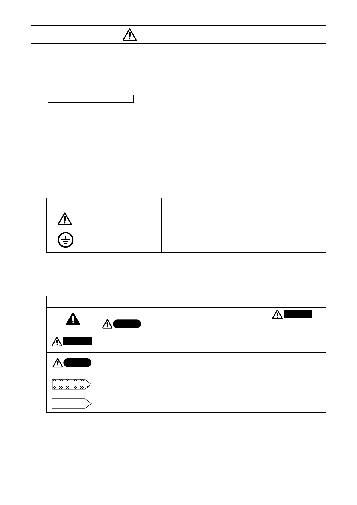
2. Labels on This Instrument
The following labels are used for safe use.
Label Name Meaning
Alert symbol mark
Protective conductor terminal
Caution on handling for prevention of an electric shock, injury
or other accidents.
A terminal is provided for connection to the protective
conductor of the power supply facility in order to prevent any
electric shocks.
3. Symbols in This Manual
Cautions to be observed for preventing damage to your recorder and unexpected accidents are indicated by the
following symbols according to their degree of importance.
Symbols Meaning of symbols
Remarks
Warning
Caution
This symbol is shown together with relevant titles (or items) where or
Caution
This symbol indicates a description of cautions for avoiding the possibility of causing
serious injury or death due to an electric shock or other accident.
This symbol indicates a description of cautions for avoiding the possibility of causing
slight injury to a person or damage to your recorder or to peripheral units.
This symbol shows a caution when your recorder does not function as specified or
when such a possibility exists.
is attached. Read them with care.
Warning
Reference
This reference serves to indicate supplementary information for handling and operation
for your convenience.
-4-
Page 6
WARNINGS
This paragraph covers important warnings for safety to be observed before reading the instructions. A full
understanding of the following warnings is required. These warnings are important for the prevention of danger to
human bodies as well as accidents with your recorder.
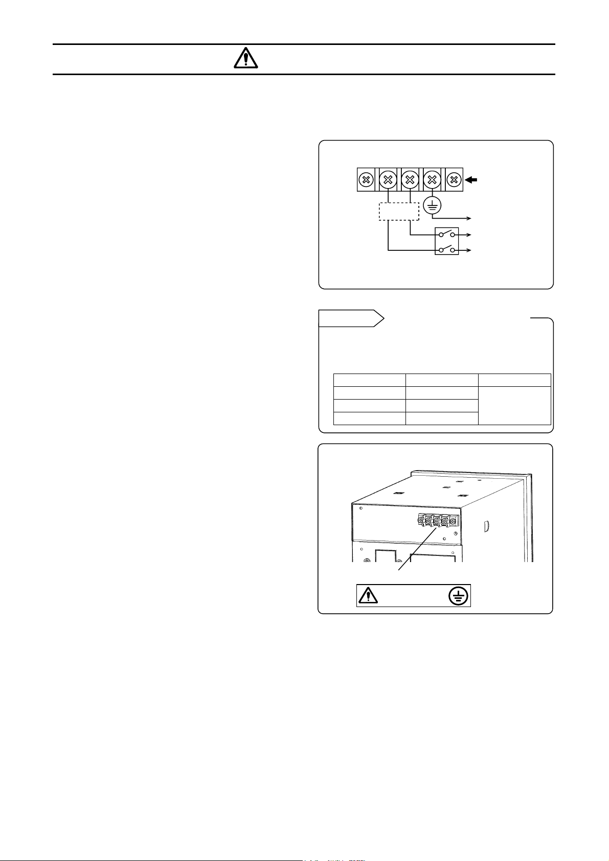
1. Switch and overcurrent
protective device
Your recorder is not provided with a power switch or
a replaceable overcurrent protective device. Prepare
a switch and an overcurrent protective device (circuit
breakers, circuit protectors or similar units) for the
power supply within 3 m of your recorder in a
location where you can reach easily.
Use a switch and an overcurrent protective device
conforming to IEC948-1 and IEC947-3.
2. Be sure to ground your recorder
Before turning on the power, connect the protective
conductor terminal your recorder to the protective
conductor of the power supply facility. Do not
disconnect this wiring in running of your recorder to
prevent an electric shock.
3. Before turning on the power
supply
In order to ensure safety, before turning on the
external power switch, make sure that the power
voltage is within the range indicated on the power
supply label.
4. Don’t repair or modify your
recorder.
Make sure that a service engineer approved by the
CHINO CORPORATION is ONLY permitted to repair
or modify your recorder by replacing parts.
Otherwise, it may be damaged or will not function
correctly, or an accident such as an electric shock
may result. For usual operation, it is not necessary to
pull out an internal unit from a case.
L
Overcurrent
protective
device
(250V 3A)
Reference
The following fuse is mounted in the power supply
unit of your recorder for safety use. However, this
fuse is not replaceable.
Note: This figure is for AL3000 series.
Manufacturer Model Ratings
SCHURTER SPT001.2508
LITTEL FUSE 21502.5
WICKMANN 19181
Power supply label
N
Switch
Power/protective
conductor
terminals
To the protective
conductor of power
supply facility
Power supply
Fuse in power supply unit
100-240VAC
50/60Hz 60VA MAX
250VAC
2.5A
5. Use your recorder in accordance with this instruction manual.
Use your recorder correctly and safely in accordance with this instruction manual. CHINO CORPORATION will
not be responsible for any injury, damage, lost profit or any other claim, which may result from its wrong use.
6.Turn off the power supply if an abnormal symptom occurs.
If any abnormal odor, noise or any smoke occurs, or if your recorder becomes too hot to be touched, turn off
the power supply immediately and contact your local CHINO sales agent.
-5-
Page 7
MAJOR FEATURES AND FUNCTIONS
Your recorder can record temperature and other various industrial variables on a 100 mm (if your recorder is
AL3000) or 180 mm (if your recorder is AH3000) chart for 1 to 4 channels (depending on the number of pens).
(1) Trace printing by pens
(2) Digital data printing to print measured values and other data
1 Features
Major features are shown below.
• Universal input. A range can be selected optionally for every channel from 10 DC voltage ranges, 36
thermocouple ranges and 11 resistance thermometer ranges.
• Universal power supply. The working voltage range is 100 to 240 V AC, 50/60 Hz.
• International safety standards…. CE: Conformance, UL and CSA (C-UL): Approval pending
• The basic operation should be carried out after programming range numbers and the trace printing range.
• You can execute all operation by the front keyboard without pulling out the internal unit. The internal unit
cannot be pulled out.
2 Functions
Major functions are shown below.
Display Printing
● Simultaneous display of the measured values for 1
to 4 channels.
● Analog indication of measured values for 1 to 4
channels with bargraphs.
● Six status lamps
● Switching the operation screens
(Measured value, Clock and Alarm Activation)
●Measured values blinks when alarm activates.
(Note)
(Note) Programming of alarm is necessary. Alarm output is only available when your recorder is with the option
of “Alarm Output”.
● Trend tracing for 1 to 4 channels
● Fixed-time printing (time line, time, scale,
engineering unit, tag)
● Periodic data printing (Measured values are
digitally printed at preset intervals.)
Digital data printing (Measured values are digitally
●
printed on demanding.)
Message printing
●
On or off of time axis synchronization (POC)
●
-6-
Page 8

MEMO
Page 9
1. GENERAL
Pen type AL3000 series and AH3000 series have various specifications. Confirm Model No. of your recorder.
Labels showing Model No. are affixed to the top side of the case and to the inside of the internal unit.
AL3000
AL373P-R20 – 00A Model
AL00 X A001 Serial No.
MADE IN JAPAN
Note: For pulling out a chart cassette, refer to Section 5.1.
1.1 Confirmation of Model No.
AH3000
AH374P – SA0 – 00A Model
AH00 X A001 Serial No.
MADE IN JAPAN
Label 1
Label 2
Label 1
Label 2
■
Models
AL37□ P -□□□- □□□
AH37□ P -□□□- □□□
Series name
A
Universal input (Fixed)
B
No. of input points (pens)/measuring cycle
C
Pen type (Fixed)
D
Communications interface (Optional)
E
Alarm output and remote contacts (Optional)
F
A B C D E F G H I
AL3: AL3000 (100 mm) AH3: AH3000 (180 mm)
1: 1 ch. (1 pen)/100 ms 2: 2 ch. (2 pens)/100 ms
3: 3 ch. (3 pens /100 ms 4: 4 ch. (4 pens)/100 ms
N: None R: RS-232C A: RS-422A S: RS-485
E: Ethernet
0: None
1: 6 MOS relay outputs + remote contacts
2: 6 mechanical relay “c” contact outputs + remote
contacts*
3: 12 MOS relay outputs + remote contacts
4: 12 mechanical relay “c” contact outputs + remote
contacts*
A: 6 mechanical relay “a” contact outputs + remote
contacts
B: 12 mechanical relay “a” contact outputs + remote
contacts
*Not conforming to CE marking, UL and CSA.
(Note) For AL3000, “0”, “1”, “2” and “A” are only
available.
J
G
Printing format (Optional)
0: Standard
1: Printing format
Math-function (Optional)
H
0: None
1: Basic math-function
2: Totalizer & flow correction
3: Basic math-function + Totalizer & flow
correction
Exterior design (Optional)
I
0: Standard
1: With carrying handle & rubber stands
2: Die-cast door for AL
3: With carrying handle & rubber stands +
Die-cast door for AL
Power supply (Fixed)
J
A: 100 – 240 V AC
-7-
Page 10
1. GENERAL
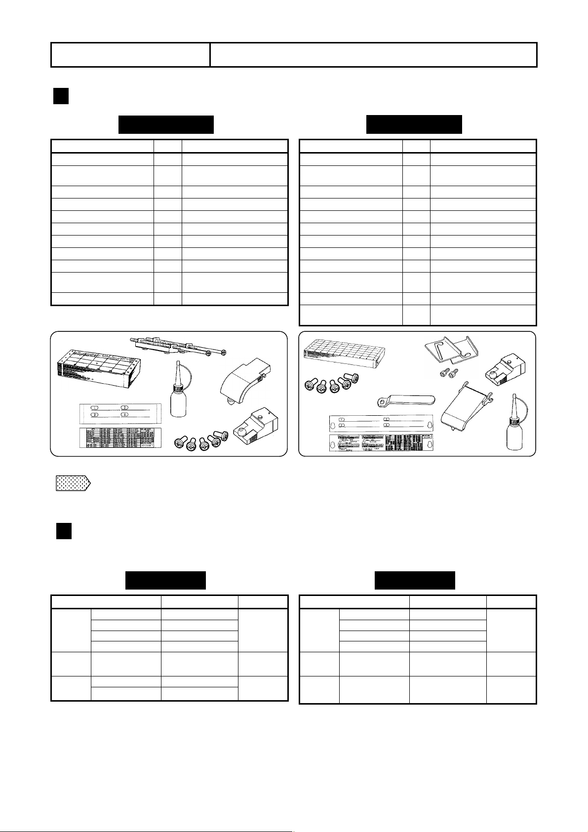
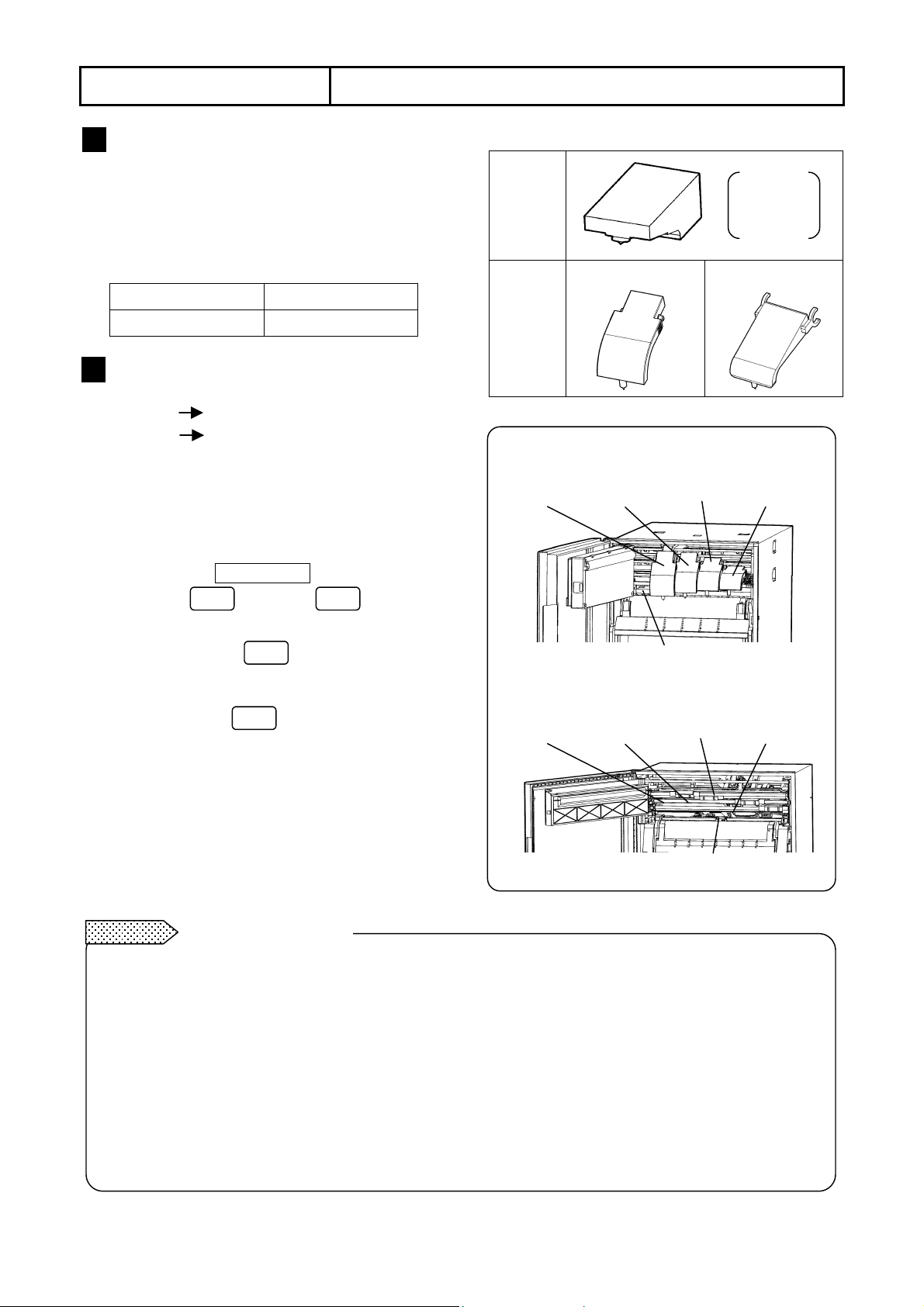
1.2 Accessories and Consumables
1 Accessories attached
Names Qty Remarks
(1) Chart 1 EM001 (0 - 100)
(2) Mounting bracket 2
(3) Channel indicating card 1 Ins ert ed ins ide the door.
(4) Cartridge pen (Red) 1
(5) Cartridge pen (Green) 1 Only for 2 to 4-pen type
(6) Cartridge pen (Blue) 1 Only for 3 to 4-pen type
(7) Cartridge pen (Brown) 1 Only for 4-pen type
(8) Plotter pen 1
(9) Terminal screw 5 Spare
(10) Lubricating oil 1
(11) Instruction manual 1 This manual
(1)
(3)
Front
Rear
Note
Separate instruction manuals are attached when your recorder is with the options of "Communications
interface" and "Math-function and totalizer”.
AL3000
For installation to a
panel.
For the main shaft of the
plotter pen
(4) – (7)
(2)
(10)
(9)
(8)
Names Qty Remarks
(1) Chart 1 EH01001 (0 -100)
2) Mounting bracket
(left, right)
(3) Channel indicating card 1 Ins ert ed ins ide the door.
(4) Cartridge pen (Red) 1
(5) Cartridge pen (Green) 1 Only for 2 to 4-pen type
(6) Cartridge pen (Blue) 1 Only for 3 to 4-pen type
(7) Cartridge pen (Brown) 1 Only for 4-pen type
(8) Plotter pen 1
(9) Terminal screw 5 Spare
(10) Lubricating oil 1
(11) Instruction manual 1 This manual
(12)Wrench 1
Front
Rear
(9)
(3)
AH3000
1 set
(1)
(12)
For installation to a
panel.
For the main shaft of the
plotter pen
For tightening mounting
bracekts
(8)
(2)
(4) – (7)
(10)
2 Consumables
Charts and pens are consumables. For your ordering, refer to the following table.
Cartridge
pen
Plotter
pen
Chart
AL3000
Article Model Min. qty
Red (1st pen) 22033-425315
Green (2nd pen) 22033-425316
Blue (3rd pen) 22033-425317
Brown (4th pen) 22033-425318
Purple 22025-425331
10 meters EM001 (0 - 100)
16 meters KL01001 (0 to 100)
3 pieces/
bag for
each color
3 pieces/
box
15 charts/
box
Cartridge
-8-
pen
Plotter
pen
Chart
Article Model Min. qty
Red (1st pen) 22034-425315
Green (2nd pen) 22034-425316
Blue (3rd pen) 22034-425317
Brown (4th pen) 22034-425318
Purple
20 meters
AH3000
22025-425331
EH01001 (0 to 100)
3 pieces/
bag for
each color
3 pieces/
box
15 charts/
box
Page 11
2. INSTALLATION
p
Location
1
Install your recorder at the following place so as not to affect the measuring accuracy and recording
operation unfavorably.
(1) Industrial environment
Select a place being separated from electric field
and magnetic field generating sources and also
free of mechanical vibrations and shocks.
• Overvoltage Category
• Pollution Degree
• Altitude
• Working place ……………..………Indoors
……………………………
(3) Ambient temperature and humidity
Make sure not to expose your recorder to direct
sunlight and not to closely place other materials to
it for preventing rise of its temperature.
• The recommended ambient temperature and
humidity are about 23°C and about 50%RH.
• Make sure not to expose your recorder to hot
air higher than 70°C.
• Make sure not place any heat source near to
the terminal board of your recorder.
………………………….
…………………………………
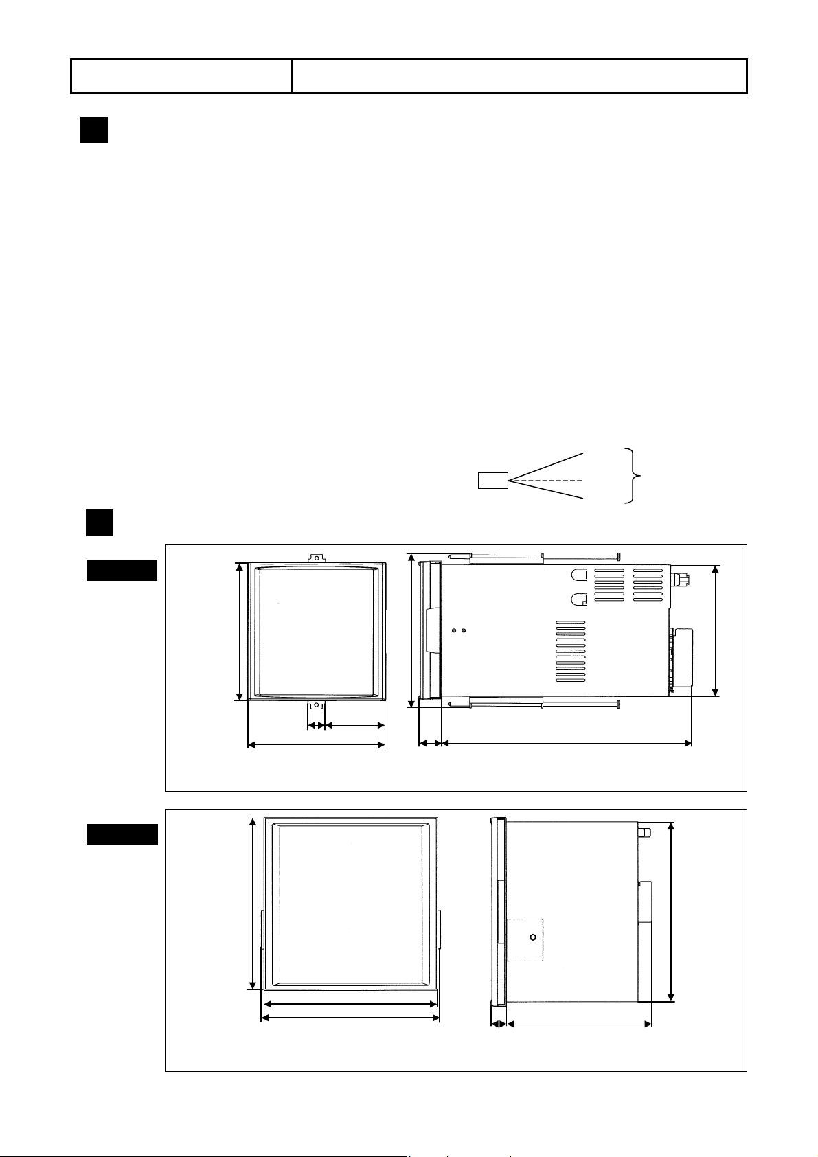
2.1 Location and External Dimensions
(2) Atmosphere
Install your recorder in a place where no
inflammable gas exists and no dust, smoke, vapor,
or other dangerous substance exists.
ΙΙ
2
2000m or lower
(4) Mounting angle and display view
angle
• Lateral tilting……….. 0° to 10°
• Longitudinal tilting…..Forward tilting: 0°
Backward tilting: 0 to 30
• View angle … -10° to +30° based on horizontal
Display
Approx.
Approx.
30°
10°
View angle
°
External Dimensions
2
AL3000
144
18
144
*1: Recorders with the options of MOS relay or ”c” contact alarm output, and communications interface
*2: Recorders with the option of “a” contact alarm output
AH3000
288
63
161
24
260(274)*1 (285)*2
277
□
137
□
288
297
*1: Recorders with the options of MOS relay or ”c” contact alarm output, and communications interface
*2: Recorders with the o
tion of “a” contact alarm output
-9-
24
220(236)*1 (247)*2
Page 12
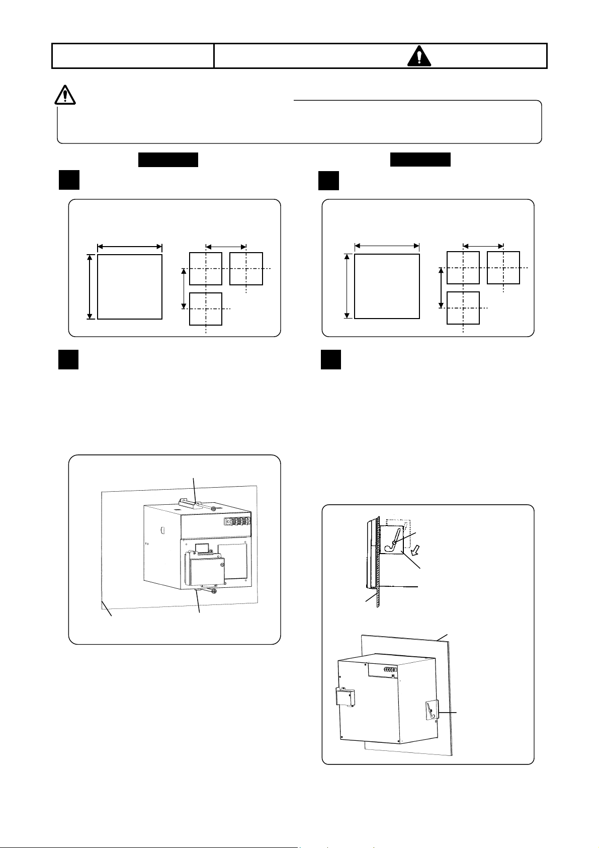
2.2 Installation to a Panel
2. INSTALLATION
Warning
Except portable types, your recorder is designed to install to a panel. Use a panel made of a steel plate of 2
mm to 6 mm in thickness.
Install your recorder to a panel.
AL3000
1
Panel cutout size
Panel cutout size
1
AH3000
0
+1
138
2
Installation
(1) Insert your AL3000 (pen type) into the panel
cutout from the front of the panel.
(2) Fix your AL3000 (pen type) to the panel by the
mounting brackets (screw tightening torque: 1.0
N•m). Attach 2 mounting brackets to the top and
bottom of this instrument.
138
+1
0
• Minimum clearance for
closed- installation
200
200
(mm)
Mounting bracket
Mounting method
+1
0
281
2
(1) Insert your AH3000 (pen type) into the panel
cutout from the front of the panel.
(2) Gently screw a mounting screw into the screw
hole of the case (left, right).
(3) Attach the mounting bracket to the case by
putting the mounting screw in the large hole of
the bracket. Slide the bracket downward to
attach it closely to the panel and then tighten
the screw with a wrench (screw tightening
torque: 1.2 N•m).
281
+1
0
• Minimum clearance for
closed- installation
360
360
(mm)
Panel thickness
(2 to 6 mm)
Mounting bracket
Mounting screw
Mounting bracket: Slide it
downward and tighten
with a wrench.
Panel
-10-
Panel thickness (2 to 6 mm)
Mounting bracket
Page 13
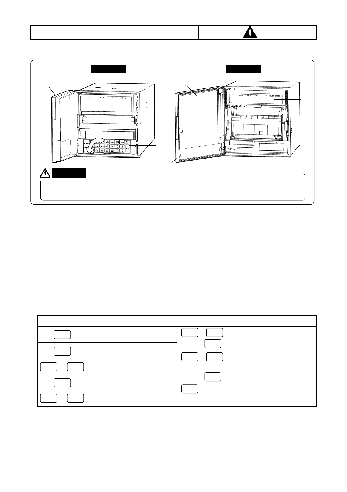
3. CONFIGULATION
DISP
FEED
SHIFT
9
0
6
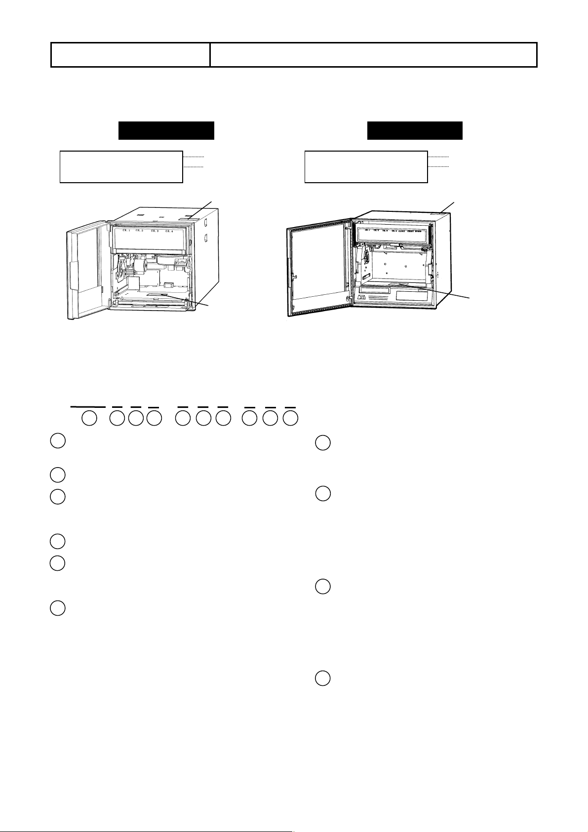
3.1 Front
All operations of your recorder including the loading of pens can be executed from its front.
AL3000
Door
Window
AH3000
Window
(1)
(2)
(3)
Warning
Door
A window of the door
The window of the door is made of glass material. To prevent injuries by destroying it, do not apply an
impact or strong force to the door.
(1) Display panel
The display panel is consisted of character displays, status lamps and bargraph displays.
For loading the pens, open the display panel by swinging it out from the right side. An illumination for chart is
mounted on the back of the display panel.
(2) Chart paper cassette
The chart paper cassette is for loading a chart to your recorder. Remove it for the loading of chart. When your
recorder is AL3000, remove the chart paper cassette by swinging down the keyboard.
(3) Keyboard
The sheet switch type keys are used in the keyboard.
● Operation keys
Keys Operations
Switches operation
screen.
Stops blinking of
display.
Switches printing on/off 6.2
Digital data printing 9.2
REC
ON/OFF
DATA
PRINT
ENTRY
ENTRY
→
Fast forwarding of chart 6.3
ENTRY
→
Ref.
page
6.4
10.3
Keys Operations
+
+
ENTRY
LIST
A~Z
*1 →
CLEAR
(3 sec. or more)
*2 →
REC
ON/OFF
(With recording disabled )
ENTRY
(3 sec. or more)
List printing 9.3
Message printing 9.4
Pen replacing mode 5.3
Ref. page
(1)
(2)
(3)
*1: Selection of List 1 or List 2. *2: Selection of Message No. (1 to 5)
● Programming keys
The keys are different on programming items. See Section 7.3 for details.
-11-
Page 14
3. CONFIGULATION
AL3000
CH 1
CH 2
CH 3
CH 4
CH 1
CH 2
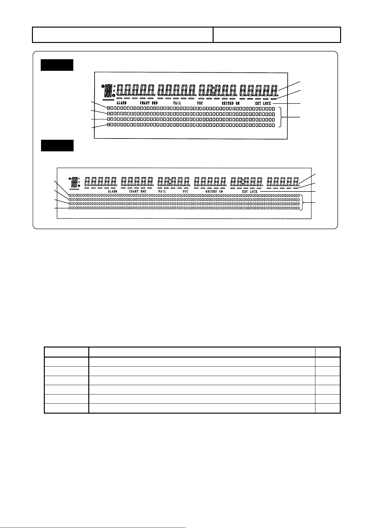
3.2 Display
CH 3
CH 4
(1)
(2)
(3)
(4)
AH3000
CH 1
CH 2
CH 3
CH 4
(1) Characters
● Operation mode: Displays measured value, time, chart speed, and alarm status of each channel (CH).
● Programming mode: Displays programming items and programming parameters in an interactive method.
(2) Underline
Shows the trace printing color of each channel (CH).
(CH 1: Red, CH 2: Green, CH3: Blue, CH 4: Brown)
These underlines also function as a cursor appearing at the digit for programming parameter in the
programming mode.
(3) Status
CHART END When the end of chart is detected. 6.2
RECORD ON When the printing is on (enable). 6.2
(4) Bargraph
The bargraphs indicate the measured value of each channel in an analog form. These indications are
interlocking to the positions of the pens for trace printing.
Resolution AL3000: 1/50 (2%), 51 segments
Display Lighting condition
ALARM When an alarm activates. 10.3
FAIL When the hardware related to servo-circuit/mechanism is abnormal.
POC When the time axis synchronization is enabled. 9.6
KEY LOCK When the keys are locked. 11.12
CH 1
See Section 6.4 for details.
AH3000: 1/100 (1%), 101 segments
CH 2
CH 3 CH 4
CLOCK
CHART SPPED
(1)
(2)
(3)
(4)
Section
-12-
Page 15
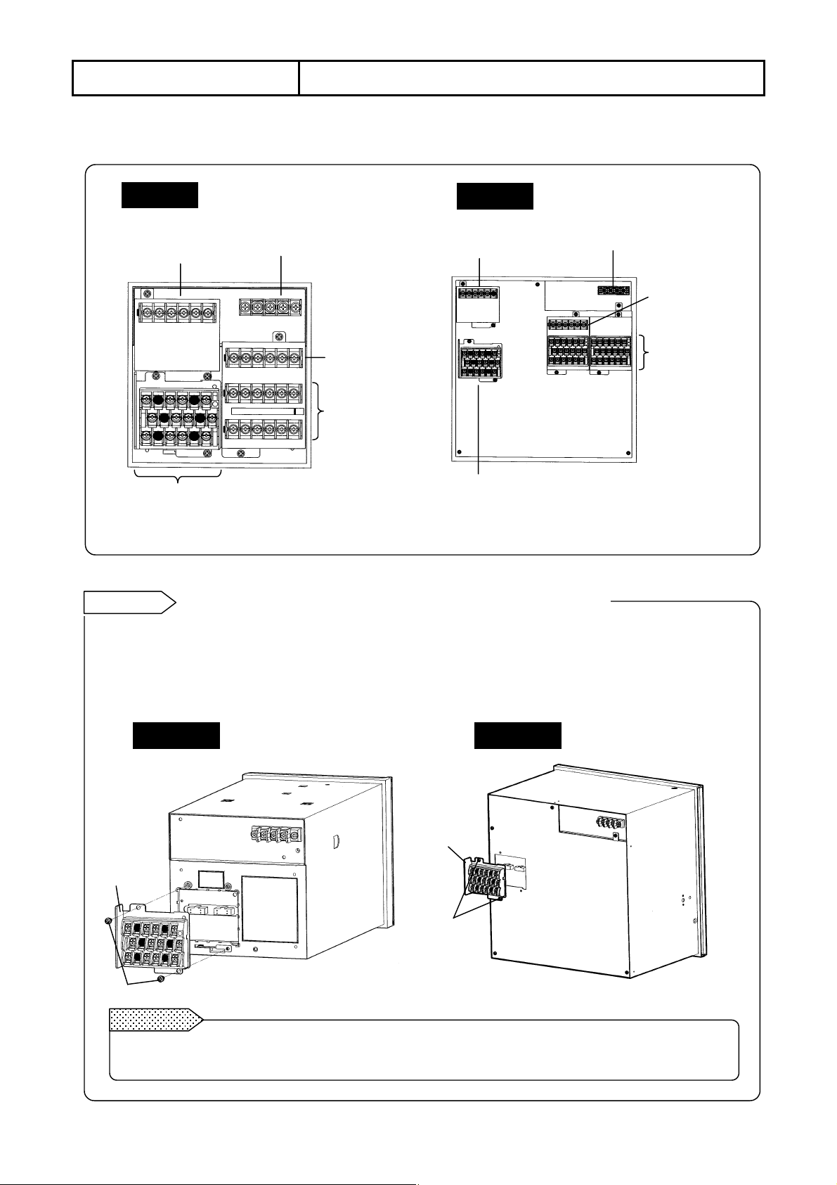
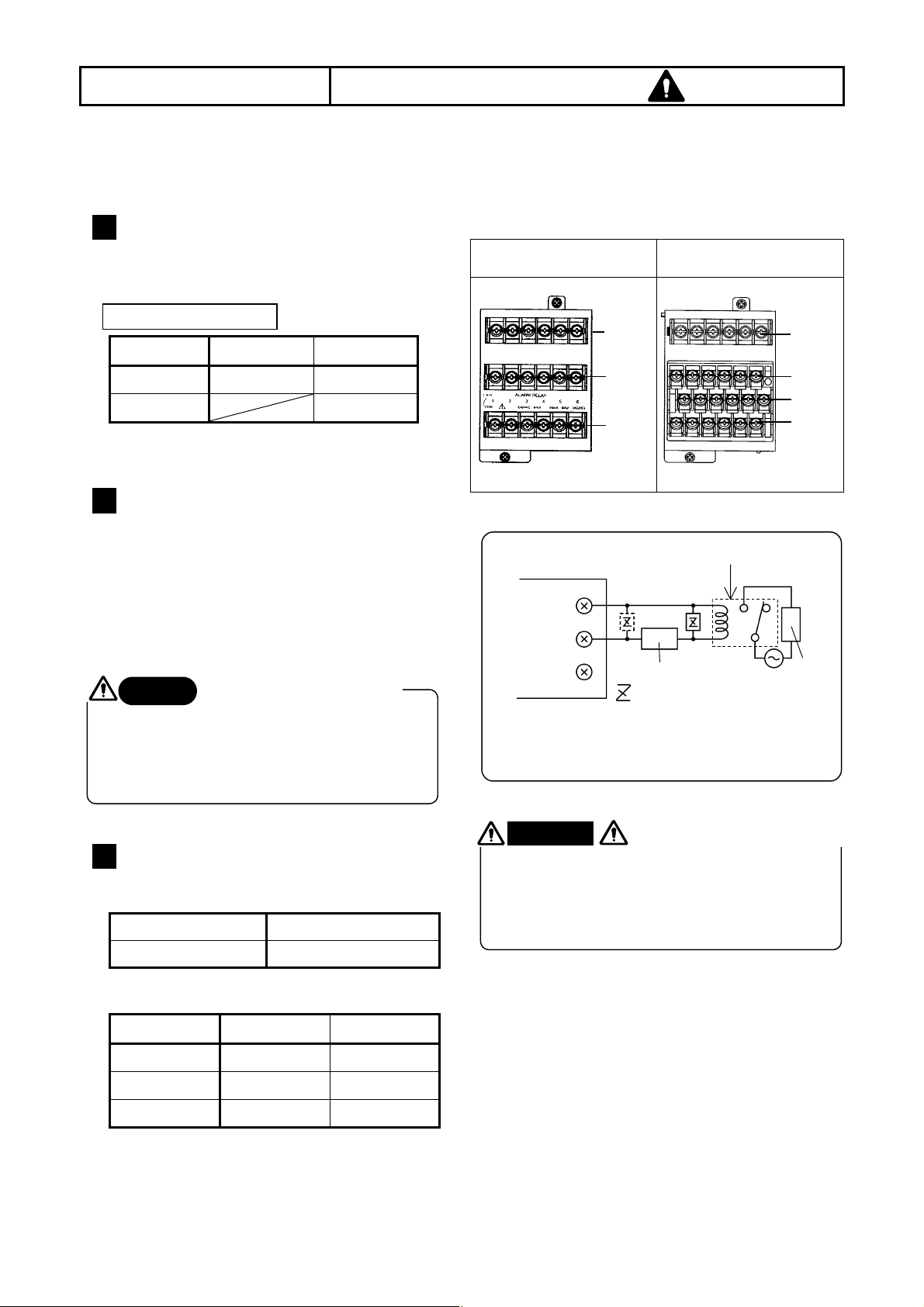
4. CONNECTIONS
4.1 Terminal Board Arrangement
The terminal boards shown in the following figure are of recorders with the options (alarm output +
remote contacts and communications interface).
AL3000
AH3000
Communications terminals
(option)
Power supply terminals
Communications terminals
(option)
Power supply terminals
Remote contacts
terminals option)
Power supply
terminals (option)
Remote contacts
terminals (option)
Power supply
terminals (option)
Measuring input terminals
Measuring input terminals
*The mechanical relay “c” contact output is consisted of three terminals of N.O, COM and N.C.
Reference
The input terminal and alarm terminal blocks are removable.
The input terminal block and alarm terminal block (including the remote contacts terminal block) are
.
removable for easy connections
Each terminal block can be taken out by removing two mounting screws.
Each terminal block is connected to your recorder by a connector. For mounting or dismounting the terminal
block, turn off the power switch to prevent the electric circuits from being damaged.
AL3000
AH3000
Input terminal
block
Input terminal
block
Mounting
screw
Mounting screw
Remarks
Removed terminals have to be remounted to the recorder to which they were originally mounted.
Mounting them to other recorders may cause a malfunction in scaling.
-13-
Page 16
4. CONNECTIONS 4.2
Observe the following cautions during connections for securing safety and reliability.
Power supply
1
Use a single-phase power supply having a stable
voltage without any waveform distortion for the
purpose of preventing wrong operations.
Warning
Prepare a switch and an overcurrent
protective device (3 A) to the power
supply for preventing an accidental
electric shock during connection work.
This instrument is not provided with any
replaceable overcurrent protective device.
Warning
Make sure to turn off the power supply
before connecting the power and the
input/output terminals to prevent an
electric shock.
2 Keep the input/output connections
away from high voltage power
circuits
Don’t place the input/output cables close to or in
parallel with any strong power circuits including
power lines. Place the cables 50cm or more away
from high voltage power circuits when they are
placed close to or in parallel to other circuits.
3 Keep the thermocouple input away
from a heat source
For thermocouple inputs, keep the input terminals
away from a heat source (a heating body) to
reduce a reference junction compensation error.
Don’t expose the input terminals to direct sunlight,
etc.
Reference
Terminal block
A switch and an overcurrent
protective device
Turn off the power supply
before starting connections
Kinds of terminals and termination
Screw
Tightening
diameter
torque
Cautions on Connections
4 Keep the input/output connections
away from noise source
Keep all connection cables away from noise
source as far as possible, otherwise a malfunction
may occur. Provide a solution if the cables cannot
be separated from a noise source due to
unavoidable circumstances.
Major noise sources Remedial measures
Electromagnetic switch,
etc. Power line having
waveform distortion,
Inverter, Thyristor regulator
.
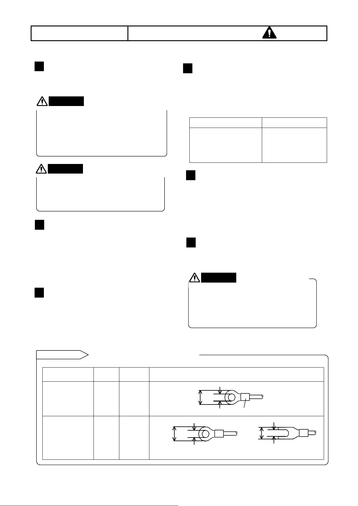
5 Use crimp style terminals
(1) Mount crimp style terminals for connection
cable terminations to prevent any looseness
or disconnection of terminals or a short-circuit
failure between terminals.
(2) Use the crimp style terminals with an
insulation sleeve to prevent an electric
shocks.
6 Unused terminals
Don’t use any unused terminals for relaying,
otherwise the electric circuits may be damaged.
Secure the connected
Warning
cables properly.
Secure the connected cables so as not to
allow them to be hooked by a person or a
substance, otherwise the connections may
be cut and disrupted, and may cause an
electric shock or other accidents.
Termination (unit: mm)
Insert noise filters
between power
terminals and
input/output terminals.
A CR filter is often used.
Power and
protective
conductor
terminals
Terminals other
than described
above
M4
M3.5
1.2N • m
0.8N • m
8 or less
*Use Type O chip (on the left) whenever possible.
8.5 or less
3.7 or more
-14-
4.3 or more
t : 0.8, with an insulation sleeve
(with an insulation sleeve)
t : 0.8, with an insulation sleeve
8 or less
3.7 or more
Page 17
4. CONNECTIONS
o
f
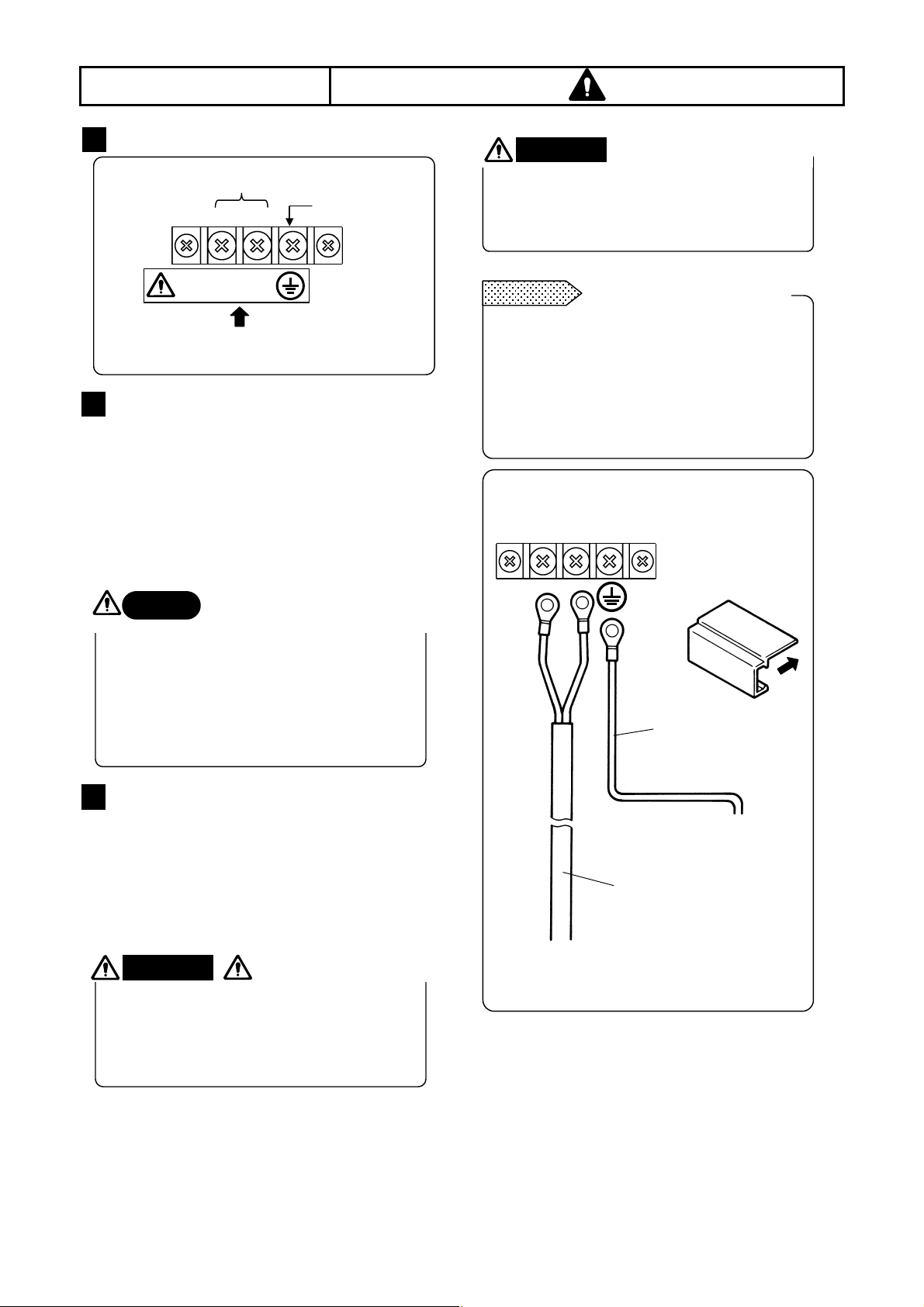
4.3 Power Terminals
1 Power and protective conductor terminals
Power supply (voltage, frequency, power consumption)
2 Connection of power terminals
For connection to the power terminals, use a 600 V PVC
insulated cable (IEC 227-3 See “Caution”) terminated by
the crimp style terminals with insulation sleeve.
Note) Use the cords approved by the following standards.
(1) IEC 227-3
(2) ANSI/UL817,
(3) CSA C22.2 No.21/49
Caution
The power voltage of your recorder is
indicated beside the power terminals. Don’t
apply any voltage other than the rated
voltage. Otherwise a malfunction may result.
If noise is contaminated in the power
supply, provide a noise reduction
transformer, etc.
Power terminals
Protective conductor
N
L
100-240V AC
50/60Hz 60VA MAX
terminal
Be careful with the power
voltage and noises.
3 Connection of protective conductor
terminal
Make sure to connect this terminal to the protective
conductor of the power supply facility. For this
connection, use a cable terminated by the crimp
style terminals with insulation sleeve.
• Grounding wire: Copper wire 2 mm
Warning
A voltage of 100 to 240 VAC is applied to the
power terminals after connections. Be sure to
mount the power terminal cover to prevent an
electric shock.
2
or more
mark at power terminals
Warning
Make sure to turn off the power supply
before the connections to the power and
protective conductor terminals for preventing
an electric shock.
Remarks
This indication conforms to the CSA
standard, Canada. The live side of the
single-phase AC power supply is
indicated as L, and the neutral side is
indicated as N. Observe the L and N
connections for obtaining satisfactory
performance.
Power supply
L N
Turn off the power supply.
L/N indication of power
terminals
600 V vinyl insulated cable
Mount the terminal cover
after connections.
(Illustration below)
A copper wire with
diameter of2 mm2 or more
(green/yellow)
Make sure to connect t
the protective conductor o
the power supply facility.
-15-
Page 18
4. CONNECTIONS
q
1 Measuring input terminals
Make sure to turn off the power supply to prevent
an electric shock.
(1) Measuring input terminals are located on the
down left of the terminal board.
(2) For the connections to the input terminals, use
cables terminated by crimp style terminals with
insulation sleeves.
Caution
Input type Allowable input voltage
Voltage,
Thermocouple input
Resistance
thermometer input
Allowable input voltage
±10 VDC (range: ±2V or less)
±60 VDC (range: ±5V or more)
4.4 Measuring Input Terminals
±6 VDC
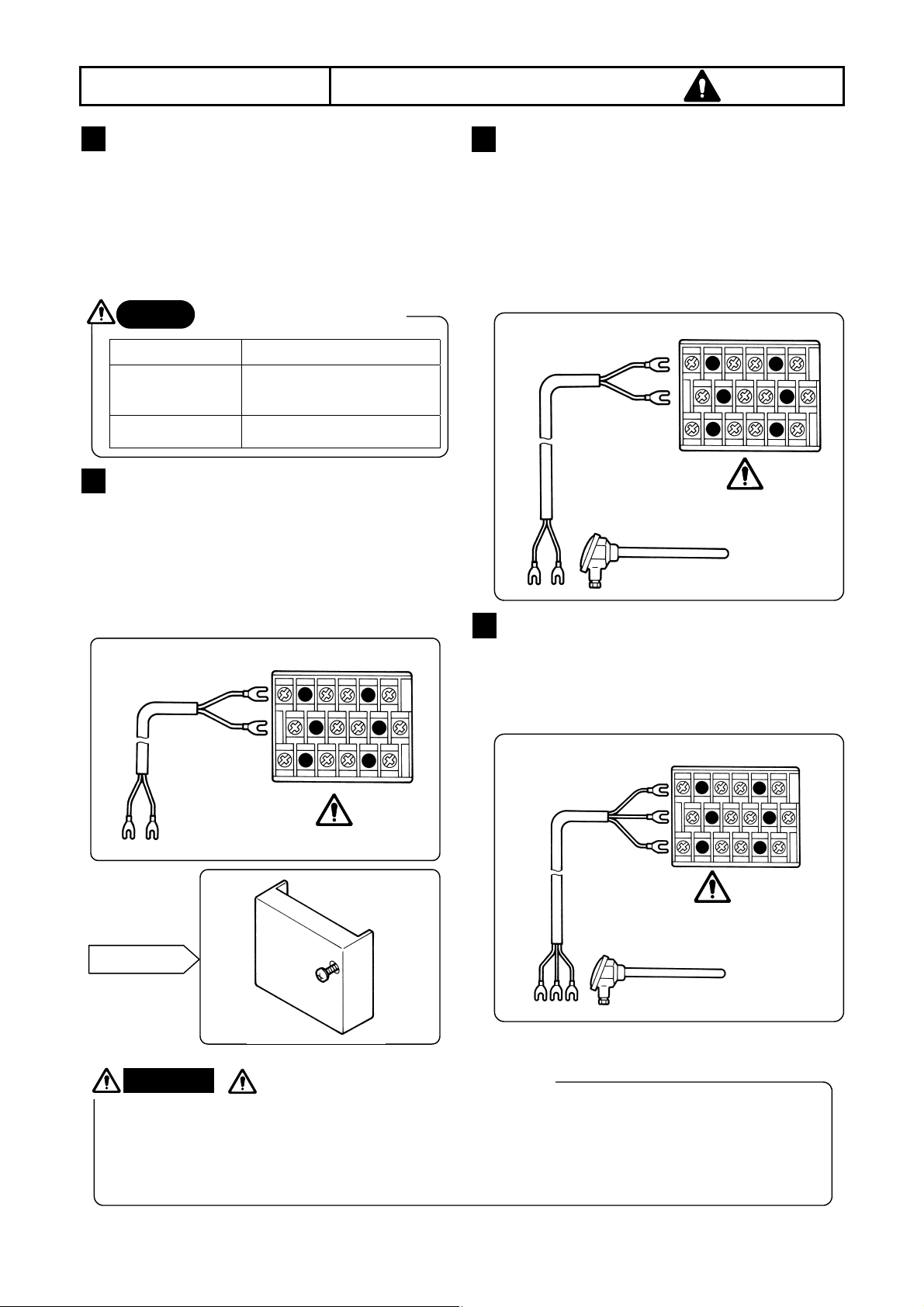
2 Connections of DC voltage (current)
input
Use twisted cables for instrumentation as the
input cables for the purpose of suppressing noise.
For current inputs, mount shunt resistors
(Section 16.2) to the channels to be measured
before connections.
3 Connections of thermocouple inputs
Make sure to use thermocouple wires (or
extension wires) to the input terminals of your
recorder. If a copper wire is used halfway, a
noticeable measuring error occurs. Don’t use a
pair of thermocouple wires in parallel with other
instruments (controller, etc.), otherwise a
malfunction may occur.
Extension wire
White (-)
1 2 3 4
Red (+)
Thermocouple
4 Connections of resistance thermometer inputs
2
1
(+)
DC voltage input
Terminal
Twisted cable for
instrumentation
cover
Warning
A high voltage may be applied to the measuring input terminals due to common mode noise. The
allowable noise value is 30 VAC or less, or 60 VDC or less. Make sure that the noise is lower than the
allowable value. Mount the terminal cover after connections for the purpose of preventing an electric
shock and to protect the input wires. In the case of thermocouple input, the mounting of the terminal cover
can reduce the reference junction compensation error.
(-)
mark of measuring input terminals
3 4
Use a 3-core cable where each lead wire has an
equal resistance value. Don’t use one resistance
thermometer in parallel with other instruments
(controller, etc.).
3-core cable
(Same diameter,
same length)
1 2 3 4
A
B
B
Note: Use a 3-core cable where
each lead wire has an equal
diameter and an e
Resistance thermometer
ual resistance
-16-
Page 19
4. CONNECTIONS
b
O
C
*
These terminals are for the alarm output (option), which is (1) MOS relay type, (2) mechanical relay “c” contact
type or (3) mechanical relay “a” contact type. The mechanical relay “c” contact type does not conform to the
international safety standards.
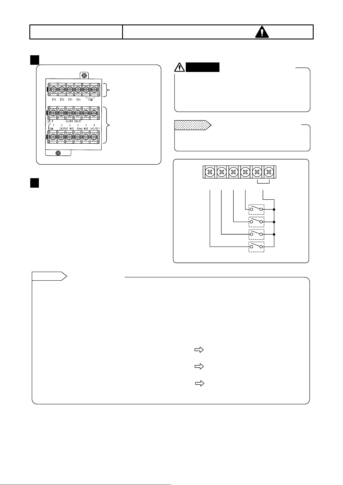
1 Alarm output terminals
The terminal arrangement depends upon the type
of alarm output.
Terminal and relay No.
Terminal block AL3000 AH3000
[Remarks]Only one terminal block is provided for
the remote contacts terminals.
2 Connections
Turn off the power supply and buffer relay power
supply before the connections for preventing an
electric shock.
(1) Connect cables to a load via a buffer relay.
(2) Use cables with crimp style terminals and
insulation sleeves for the alarm output
terminals.
Caution
The alarm output of your recorder may
become defective. This may be caused by
wrong operation, failure or other abnormal
inputs. Take safety measures against an
output failure before use if necessary.
3 Cautions on connections
1) Output contact rating
(1) MOS relay
Maximum voltage 240 V (AC, DC)
Maximum current 50 mA (AC, DC)
(2) Mechanical relay
Power supply Resistive load Inductive load
100 VAC 0.5 A 0.2 A
240 V AC 0.2 A 0.1 A
100 V DC 0.3 A 0.1 A
1 No. 1 to 6 No. 1 to 6
2 No. 1 to 12
Take safety measures.
4.5 Alarm Output Terminals
MOS relay/Mechanical
relay “a” contact
123456
123456
Your recorder
2) Mounting of contact protective element
N.
COM
N.
* N.C terminal: Only for the mechanical relay “c” contact
output
Warning
A buffer relay power supply is applied to the
alarm output terminals after connections. Don’t
touch these terminals for preventing an electric
shock. Make sure to mount the terminal cover
after connection.
(1) Mount a contact protective element
conforming to the buffer relay.
(2) To prevent a malfunction being caused by a
light load, the most effective mounting position
for the element is on the coil side of the buffer
relay ('a' in the above diagrams)
(3) The MOS relay will be broken, even if a
signal exceeding the contact rating is
momentarily applied.
Mechanical relay “c”
contact
Remote
contacts
123456
N.O
COM
Power supply
: Contact protective element (It is
recommended to mount this
element on the “a” side.)
Buffer relay
a
mark for alarm output terminals
Remote
contacts
N.O
COM
N.C
Load
-17-
Page 20
4. CONNECTIONS
A
These terminals are for the remote contacts (option). For the remote contacts, see Section 13.
1 Remote contacts terminals
2 Wiring
To prevent an electric shock, make sure to
turn off the power supply before wirings.
(1) The signals applied to the remote contacts
(2) Connect wires to the remote contacts
Reference
1. Remote contacts operations
(1) Printing ON/OFF and chart speed
(2) Message (Nos. 1 to 5) selection and
(3) Message (Nos. 1 and 2) selection and
(4) Digital data printing *
(5) List (Nos. 1 to 3) printing *
(6) Operation record (Nos. A to D) printing *
(7) "Totalizing" (option) reset *
* Using any one terminal.
terminals should be non-voltage contact
signals.
terminals with crimp style terminals and
insulation sleeves
Remote contacts
selection from 3 speeds (Using 2
terminals EX1 and EX2)
printing (Using all of 4 terminals EX1 to
EX4)
printing (Using 2 terminals EX3 and EX4)
4.6 Remote Contacts Terminals
Remote contacts
terminals
larm output terminal
(option)
For the contacts to be connected to the remote
contacts terminals, use a switch or relay driven at
30 VAC or lower, or 60 VDC or lower, or manual
contacts for very light loads.
Remarks
• Voltage when the contact is open: Approx. 5 V
• Current when the contact is short: Approx. 2 mA
2. Terminal allocation for operation
It is required to set operations to be allocated
to each terminal (EX1 to EX4).
3. Operations to be set
(1) Printing ON/OFF and chart speed
selection from 3 speeds
(2) Message selection and printing
(3) Operation recording
Remote contacts terminals
EX1 EX2
Setting of 3 chart speeds
Setting of messages Nos. 1 to 5
Setting of recording positions of
operation records Nos. A to D
No-voltage contacts Warning
EX3 EX4
COM
-18-
Page 21
4. CONNECTIONS
4.7 Communications terminals
These terminals are for the communications interface (option). For details of the connection, refer to the instruction
manual for the “Communications Interfaces” provided separately.
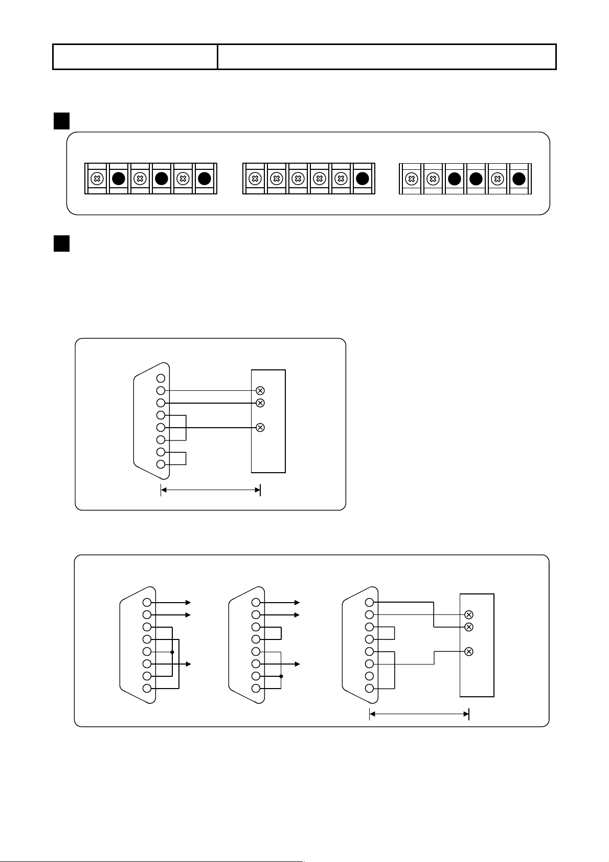
1 Communications terminals
RS-232C Terminals RS-422A Terminals RS-485 Terminals
SD
RD SG
SDA
SDB
RDA
RDB
SG
SA
SB
SG
2 RS-232C Connections
When your recorder is with the communications interface of RS-232C, three terminals of SD, RD and SG are
used but any control signal is not used. General personal computers are controlled by control signal. Wiring
processing for control signal in a connector depends upon how the control signal is used in a personal computer.
For details, refer to the instruction manual for your personal computer.
1) 9-pin connector
2) 25-pin connector
Personal computer
1
CD
2
RD
3
SD
4
ER
SG
5
DR
6
RS
7
CS
8
Your recorder
SD
RD
SG
Within 15 m
Personal computer
(Ex. 3)
2
SD
3
RD
4
RS
CS
5
DR
6
SG
7
CD
8
ER
20
Personal computer
RD
SD
SG
(Ex. 2)
SD
RD
RS
CS
DR
SG
CD
ER
2
3
4
5
6
7
8
20
-19-
RD
SD
SG
Personal computer
(Ex. 3)
2
SD
3
RD
4
RS
CS
5
DR
6
SG
7
CD
8
ER
20
Within 15 m
Your recorder
SD
RD
SG
Page 22
4. CONNECTIONS
E
A
A
4.7 Communications terminals
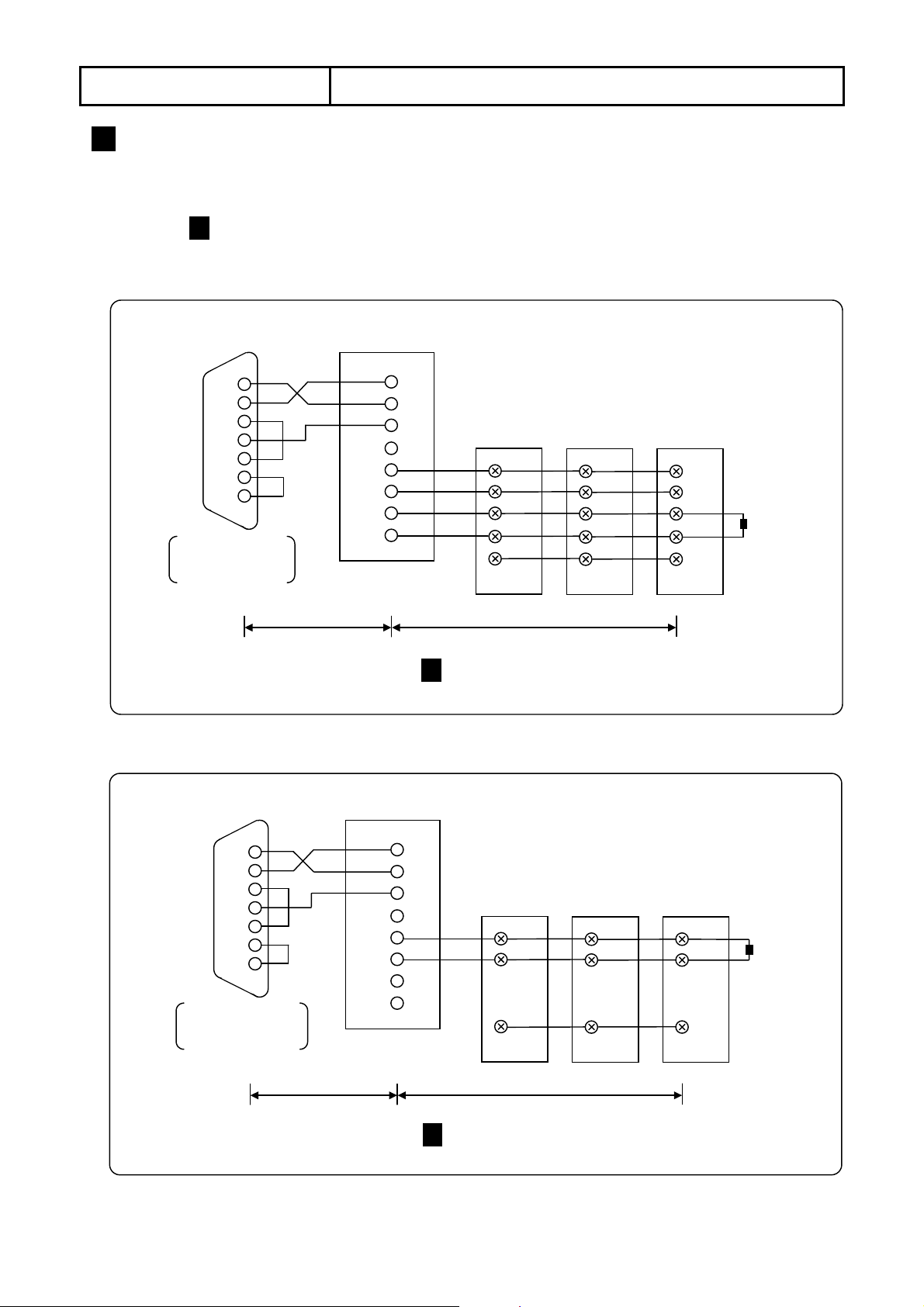
3 RS-422A, RS-485 Connections
RS-422/485 communications interface is connected to a personal computer via a line converter (our Model
SC8-10: sold separately). Three signals of SD, RD and SG are used between the line converter and the
personal computer but any control signal is not used. Wiring processing for control signal in a connector is
necessary in the same as 2 RS-232C connections.
1) RS-422A
Personal computer
(9-pin or 25-pin connector)
2
RD
SD
3
ER
4
SG
5
DR
6
RS
7
CS
8
Example of 9-in
connector
*
Line converter
(SC8-10)
RD
1
2
SD
SG
3
4
RDA
5
RDB
6
SDA
7
8
SDB
L3000/AH3000 hybrid recorders
(1) (2)
SDA
SDB
RDA
RDB
SG
Within 15 m
Within a total length of 1.2 km (max. 31 recorders)
*For the details of the wiring, refer to 2 RS-232C connections.
SDA
SDB
RDA
RDB
SG
(3)
SDA
SDB
RDA
RDB
SG
Termination
resistance
100 Ω, 1/4W
2) RS-485
(9-pin or 25-pin connector)
Personal computer
2
RD
SD
3
ER
4
SG
5
DR
6
RS
7
CS
8
*
Line converter
(SC8-10)
RDA
RDB
SDA
SDB
RD
1
2
SD
SG
3
4
5
6
7
8
L3000/AH3000 hybrid recorders
(1) (2) (3)
SA
SB
xample of 9-in
connector
Within 15 m
Within a total length of 1.2 km (max. 31 recorders)
SG
*For the details of the wiring, refer to 2 RS-232C connections”.
SA
SB
SG
SA
SB
SG
Termination
resistance
100 Ω, 1/4W
-20-
Page 23
5. INSTALLATION
g
5.1 Chart Paper Loading (AL3000)
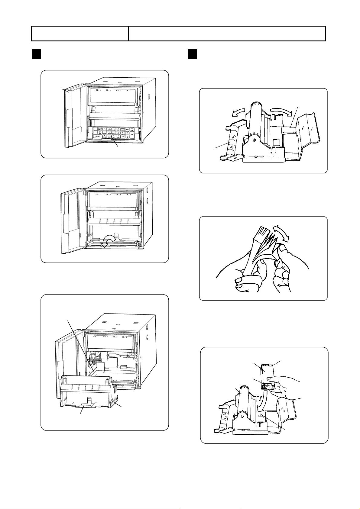
1 Chart Paper Cassette Removal
1) Open the door.
Door
2) Swing down the keyboard.
3) Remove the chart paper cassette.
Pens lift up when the chart paper cassette is
removed.
Guide rail
Keyboard
2 Chart Paper Loading
1) Open the chart paper holders.
Open the chart paper guide and the stripper
plate.
Chart
paper
uide
2) Prepare a chart paper
Shuffle both end of the chart paper to prevent
two or more chart papers from fed being
together.
3) Put it into the chart paper housing.
The shapes of the sprocket holes on the right
and left sides are different. The right side holes
are an elliptical shape.
Stripper plate
Printing side
Sprocket holes (elliptical)
Drum
Guide
Grip
-21-
Sprocket holes (circular)
Chart paper
housing
Page 24
5. INSTALLATION
FEED
ENTRY
5.1 Chart Paper Loading (AL3000)
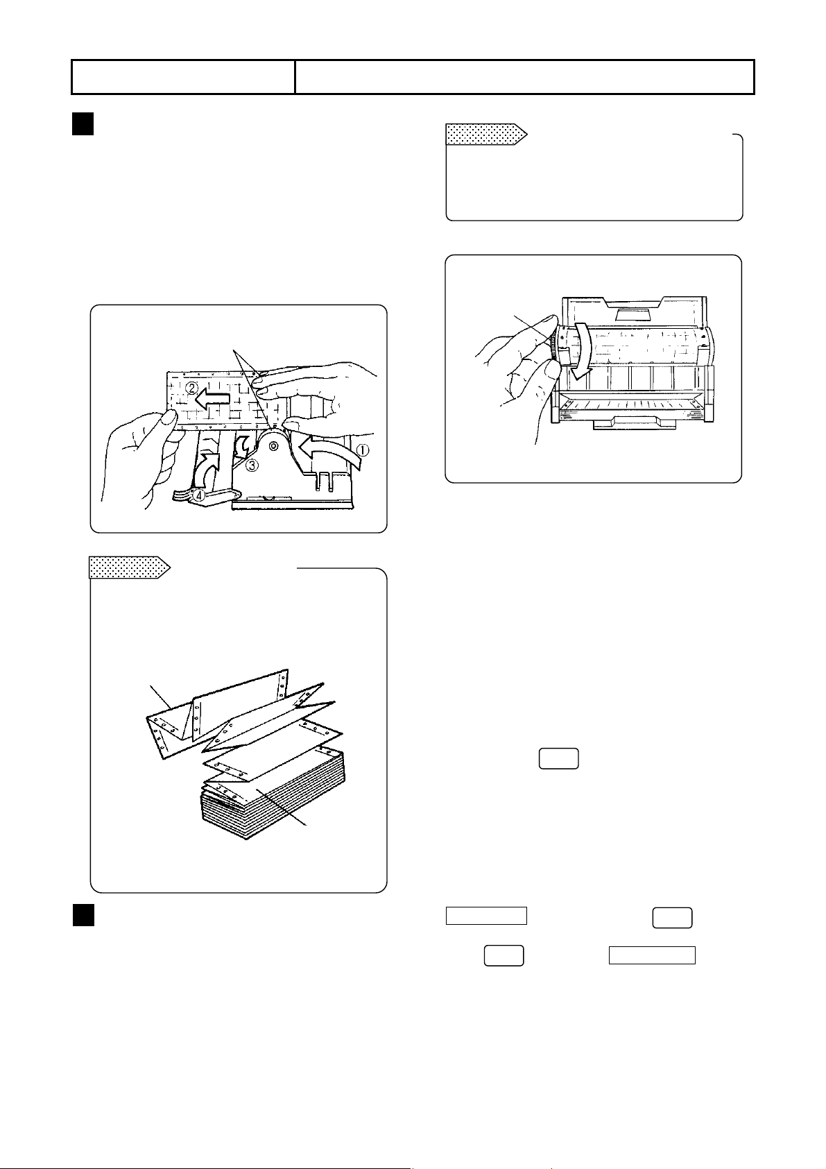
3 Chart Paper Setting
1) Draw out the chart paper approx. 20 cm and
close the rear stripper plate.
2) Set the holes on the chart paper over the
sprockets at both ends of the drum.
3) Use the thumb wheel to advance the chart
paper for 2 to 3 folds into the chart tray.
4) Close the front chart paper guide. Make sure
that the holes are set over the sprockets.
Set the holes on the chart paper to the sprockets.
Remarks
Don’t insert the chart paper folds reversely
when inserting the chart paper into the chart
paper tray, otherwise a folding failure results.
Chart paper folds
Folding section
Chart paper
4 Check
1) Manual check
Turn the thumb wheel by hand to make sure
that the chart paper is feeding properly.
Remarks
Don’t turn the thumb wheel inward. The chart
paper cannot be fed backward. This action
may cause a chart paper feed failure.
2) Place the chart paper cassette in its original
position
Place the chart paper cassette with the chart
paper loaded in your recorder.
(1) Guide rails for the chart paper cassette are
located on the right and left side of the internal
unit. Set the guides of the chart paper cassette to
the guide rails and push it until it clicks into place.
(2) Return the keyboard back in its original position.
3) Chart paper feeding check
(1) Turn on the power supply.
(2) Press the key and check the chart
paper feeds smoothly.
(3) Repeat the above procedure if the chart paper
is not fed smoothly.
4) Operation during chart end detection
When the chart paper cassette is returned in the
internal unit during the chart end detection, the
CHART END display blinks. Press to turn it
from blinking to steady lighting.
Press again. The CHARD END display
goes out and the chart paper is fed automatically.
Turning direction of thumb wheel
Thumb wheel
(Top view)
ENTRY
-22-
Page 25
5. INSTALLATION
5.2 Chart Paper Loading (AH3000)
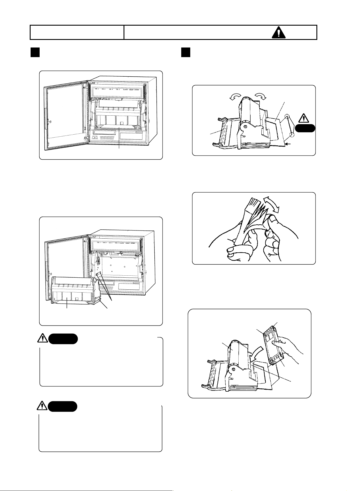
1 Chart Paper Cassette Removal
1) Open the door.
2) Remove the chart paper cassette.
(1) Pull the grip of the chart paper cassette and
take the chart paper cassette slightly out of
the internal unit. (Pens lift up.)
(2) Pull the grip slowly to take the chart paper
cassette out of the internal unit completely.
Chart paper cassette
Be careful with the corners
Caution
of the rear stripper plate
The sharp corners of the rear stripper plate
help to feed the chart paper smoothly. Be
careful not to cut your fingers when loading
or replacing the chart paper.
Caution
Don’t remove the chart paper cassette
during printing by a plotter pen. The
cassette may hit 1st pen during the
automatic pen lift-up function executed.
Grip
Guide
Guide rail
Don’t remove the chart paper
cassette during printing.
2 Chart Paper Loading
1) Open the chart paper holders.
Open the chart paper guide and the stripper
plate.
Chart
paper
guide
2) Prepare a chart paper.
Shuffle both end of the chart paper to prevent
two or more chart papers fed being together.
3) Put it into the chart paper housing.
The shapes of the sprocket holes on the right and
left sides are different. The right side holes are an
elliptical shape.
Printing side (Caution in red)
Drum
Sprocket holes (circular)
Stripper plate
Caution
Open from
here.
Sprocket holes
(elliptical)
Chart paper
housing
-23-
Page 26
5. INSTALLATION
凸
FEED
ENTRY
ENTRY
5.2 Chart Paper Loading (AH3000)
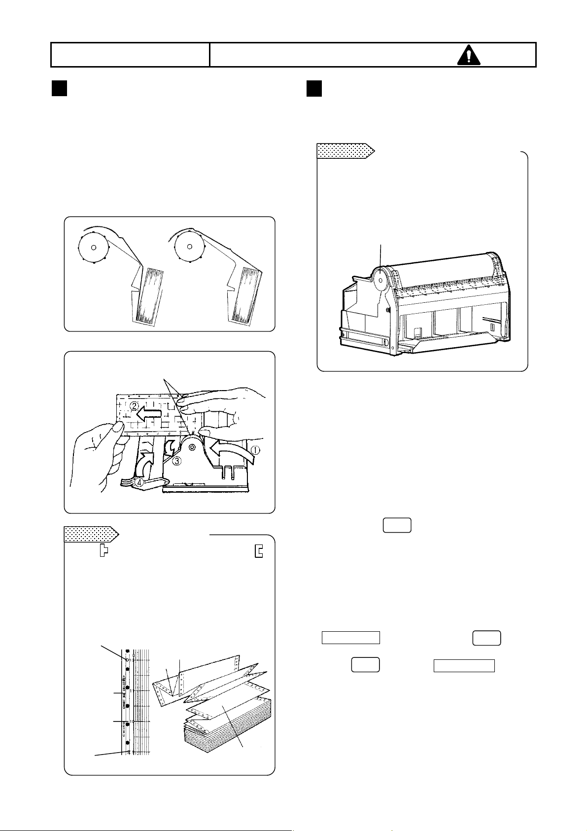
3 Chart Paper Setting
1) Draw out the chart paper approx. 50 cm and
close the rear stripper plate.
2) Set the holes on chart paper over the sprockets at
both ends of the drum.
3) Use the thumb wheel to advance the chart paper
for 2 to 3 folds into the chart tray.
4) Close the front chart paper guide. Make sure that
the holes are set over the sprockets.
○
Set the holes of the chart paper on the sprockets.
Remarks
The mark for fold thread parts and the
mark for fold valley parts are printed on both
ends of the chart paper.
Don’t insert the chart paper folds the wrong
way when inserting the chart paper into the
chart paper tray, otherwise a folding failure
will result.
凸
Chart paper
No.
Time scale
Chart paper folds
mark (Fold thread)
mark
×
凹
mark
4 Check
1) Manual check
Turn the thumb wheel by hand to make sure that
the chart paper is feeding properly.
Remarks
Don’t turn the thumb wheel inward. The chart
paper cannot be fed backward. This action
may cause a chart feed failure.
2) Place the chart paper cassette in its the original
3) Chart paper feeding check
Thumb wheel
position
Guide rails for the chart paper cassette are located
on the right and left side of the internal unit. Set the
guides of the chart paper cassette to the guide
rails and push it until it clicks into place.
(1) Turn on the power supply.
(2) Press the key and check that chart
paper feeds smoothly.
(3) Repeat the above procedure if the chart paper
is not fed smoothly.
4) Operation during chart paper end detection
When the chart paper cassette is returned in the
internal unit during the chart end detection, the
CHART END display blinks. Press to turn
it from blinking to steady lighting.
Press again. The CHARD END display
goes out and the chart paper is fed automatically.
.
Turning direction of the thumb wheel
凹 mark (Fold valley)
Chart paper
-24-
Page 27
5. INSTALLATION
5.3 Recording Pen Loading
1 Recording Pen Types
(1) There are two types of recording pens, the
plotter pens for use in digital printing and
cartridge pen for use in trace printing.
(2) There are four kinds of cartridge pens for 1
pen to 4
th
pen. These are of same shape but
differ in ink colors.
st
pen: Red 3rd pen: Blue
1
2nd pen: Green 4th pen: Brown
Plotter
st
pen
For AL3000 For AH3000
Cartridge
pen
Common for
the AL3000
and AH3000
2 Preparation for Installation
1) To remove the chart paper cassette
AL3000 See Section 5.1.1.
AH3000 See Section 5.2.1.
2) Open the display panel.
Swing out the panel from the right edge.
3) Set to the pen replacement mode.
(1) Turn on the power supply.
(2) If the status RECORD ON lights, go it out by
pressing and then . (Pens lift
REC
ON/OFF
ENTRY
up.)
(3) Press and hold down for 3 seconds.
REC
ON/OFF
The pens return to original positions and then
move to the center.
(4) Each press of moves each pen to
ENTRY
the "zero" position. Replace each pen at its
“zero” position.
Remarks
Maintenance of pens
1. Pen tip
The pen tip is made of felt material. If an excessive force is added to it, the top of the pen tip will be
crushed making clear printing or tracing impossible.
2. Pen cap
Each pen is provided with a pen cap for preventing drying and protecting the pen tip. Remove and retain
the pen caps before the pen installation.
3. Before stopping recording for long hours
When it is expected that recording will not be executed for a day or more, remove and store the pens by
attaching the pen cap to them. If the pens are left installed while no recording is executed, the ink will
stain the chart paper.
• Pen holders for AL3000
4th pen
3rd pen
• Pen holders for AH3000
4th pen
3rd pen
2nd pen
Plotter pen
2nd pen
Plotter pen
1st pen
1st pen
-25-
Page 28
5. INSTALLATION
5.3 Recording Pen Loading
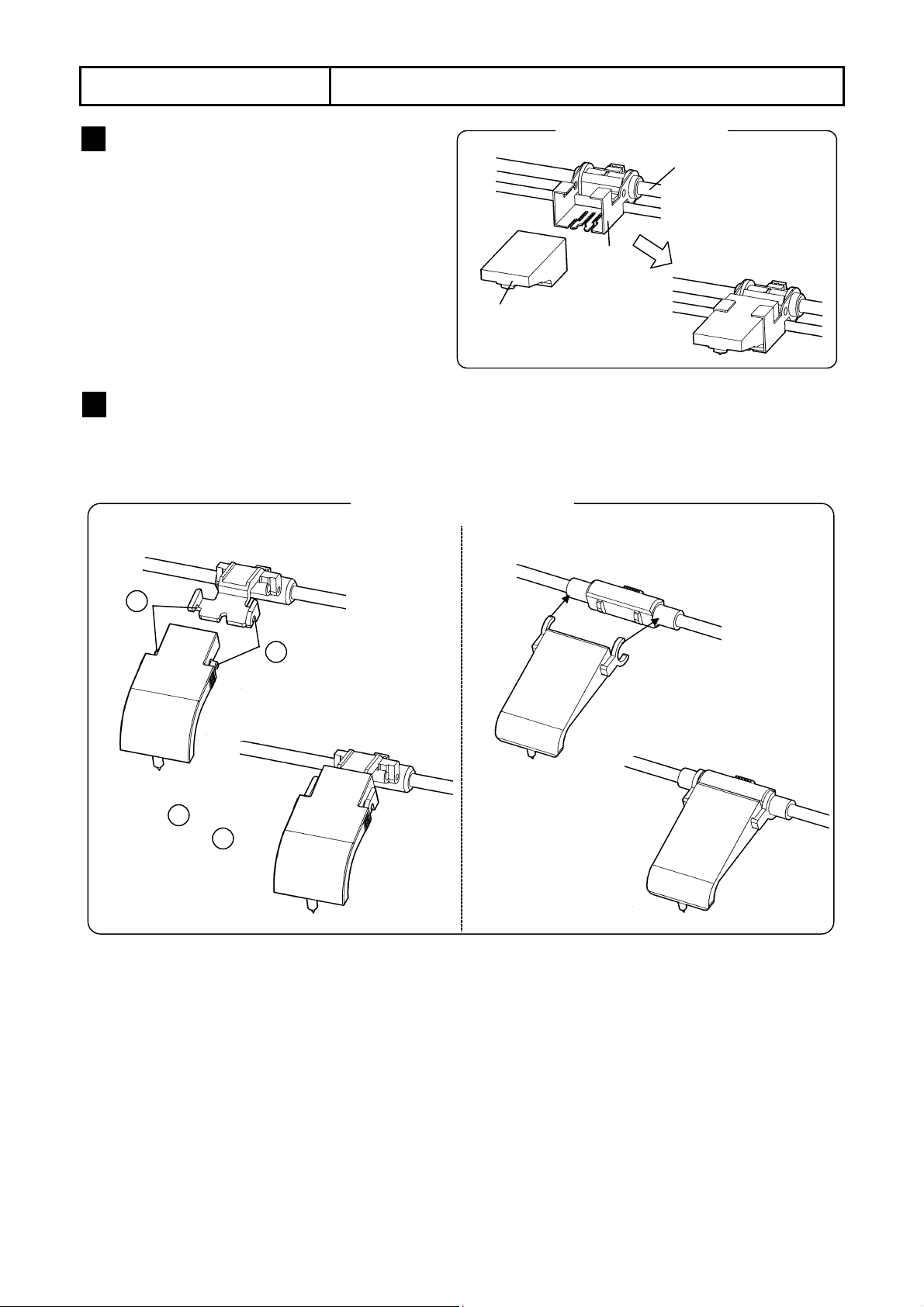
3 Plotter Pen Loading
(1) Before loading, remove the pen cap from
the plotter pen and write letters on a paper,
etc. for testing.
(2) Insert the plotter pen into its penholder
completely.
(Note) Incomplete insertion may result in
recording troubles.
(3) For unloading of the plotter pen, pull it from
the penholder.
Plotter pen
Plotter pen loading
Penholder
Main shaft
4 Cartridge Pen Loading
(1) Before loading, remove the pen cap from the cartridge pen and write letters on a paper, etc. for testing.
(2) Push the cartridge pen into the penholder for the same pen No. as the pen.
• AL3000
Cartridge Pen Loading
•
AH3000
2
1
Push in.
Insert first,
then push in .
(3) For unloading of the cartridge pen,
1
2
● AL3000: Pull out the left side of the pen from the holder, and then take off it by disengage its
convex part at the right side of the holder.
● AH3000: Pull the pen from the holder.
-26-
Page 29
e
6.
(
)
BASIC OPERATION
6.1 Power Supply and Operation
1 Power Supply On/Off
Your recorder is not provided with a power switch.
Prepare an external power switch for turning on or
off its power supply.
2 Initial Operation
By turning on the power supply, 1) year, month and
day are displayed. After initialization, 2) year, month,
day and time are printed (Printing when the power
is turned on) and 3) the normal operation starts.
Overcurrent
protective device
250V 3A
Power switch installation
L
N
To protective conductor of
power supply facility
Power switch
Power and protective
conductor terminals
Power supply source
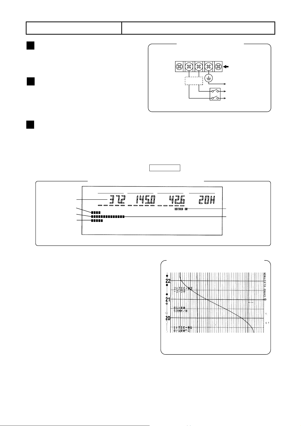
3 Operation
1) Operation screen
(1) Measured values for all channels (CH 1 to 4: depending on the numbers of input points) are digitally
displayed.
(2) Measured values for all channels (CH 1 to 4: depending on the numbers of input points) are displayed by
bargraphs.
(3) A corresponding status lamp lights. The default is RECORD ON.
2) Chart paper feeding
3) Printing
Measured valu
CH 1
CH 2
CH 3
The chart paper is fed at the programmed chart paper
speed. (The default speed is 20 mm/h for AL3000 and
25 mm/h for AH3000.)
(1) Trace printing
Measured values are traced by a cartridge pen.
<Ink colors> CH 1: Red, CH 2: Green, CH 3: Blue, CH 4: Brown
(2) Digital data printing
a. Fixed-time printing
The following data is printed at preset time intervals.
•Time line •Time •Year/Month/Day •Chart speed
•Scale •Engineering unit •Tag
b. Other printings
The following printings are executed according to programming and operation.
•Periodic data printing •Digital data printing •List 1, 2 and 3 •Programming change mark
•Alarm activation/reset •Message •Operation printing line and No. •Time axis synchronization mark
Example of operation screen (3-pen type)
Ch 1 Ch 2 Ch 3
(Note) The above example is for AL3000. It is the same for AH3000.
Chart speed
Trace printing and fixed-time printing
(Note) The above example is for AL3000.
It is the same for AH3000.
Status
Bargraph
-27-
Page 30
6.
BASIC OPERATION
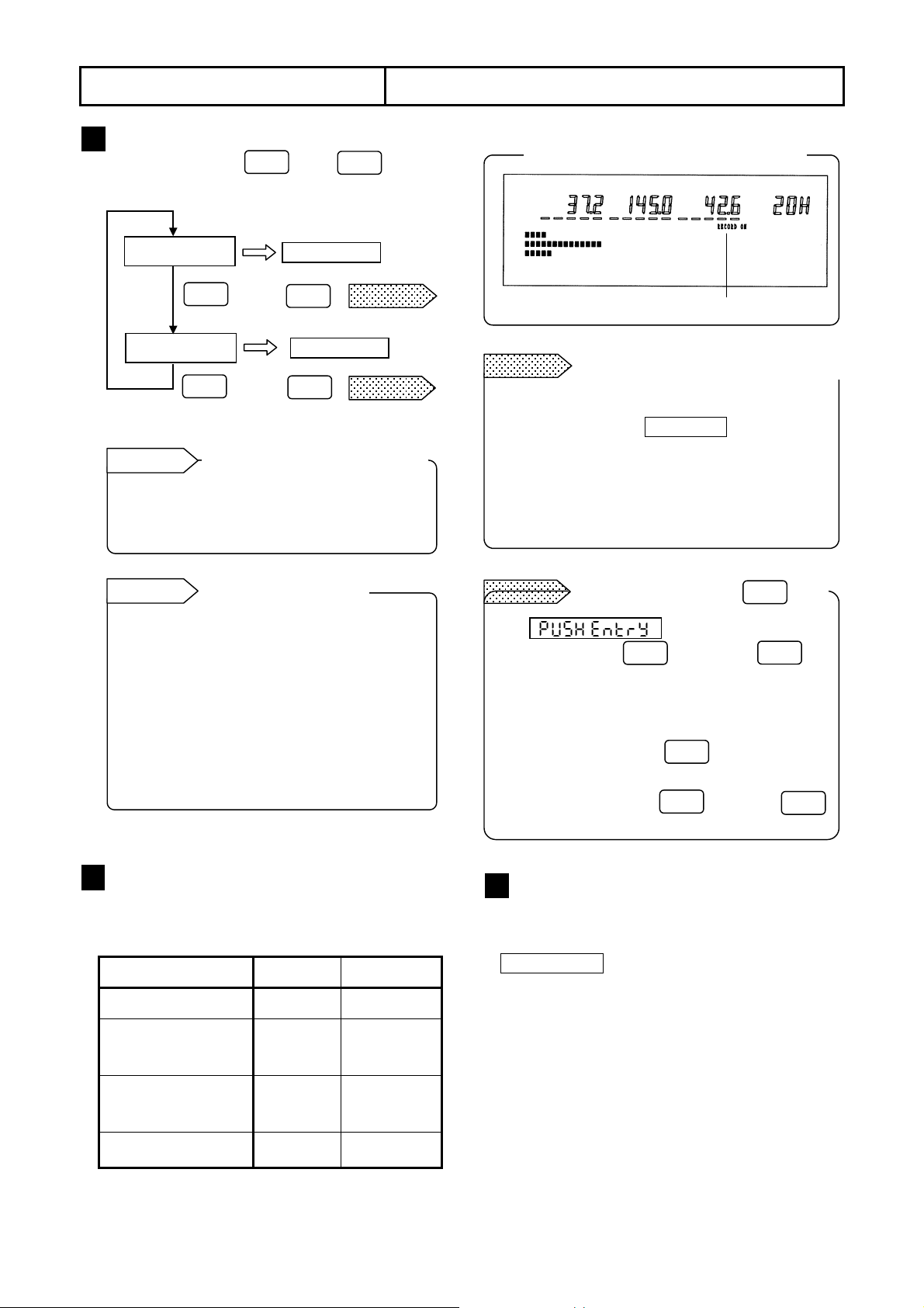
6.2 Printing ON/OFF and chart end detection
1 Printing On/Off
Every time pressing then within 5
REC
ON/OFF
sec., the printing function switches to on or off.
Printing ON
RECORD ON
REC
ON/OFF
→
ENTRY
Printing OFF
RECORD OFF
REC
ON/OFF
→
ENTRY
Reference 1
Printing status when turning on
the power supply
When turning on the power supply, the printing
maintains the condition (on or off) when it was
turned off last time.
Reference 2
Up and down of pens
(1) When the printing is turned off, each pen
lifts up automatically. Even if the power is
turned off in this condition, this pen
position is maintained.
(2) When the chart cassette is pulled out,
each pen lifts up. If the printing has been
turned off when pulling out the chart
cassette, each pen has already been lifted
up and it maintains its position.
ENTRY
Status
lights.
Remarks 1
Status
goes out.
Remarks 2
2 Printing Operation
The table below explains the printing operation
when the printing is on or off.
Operation ON OFF
Chart feeding Execute Stop
Trace printing
(Cartridge pen)
Digital data printing
(Plotter pen)
Execute
Execute
Up where it
is
Up at
standby
position
Status display when printing is on
Lights when the printing is on.
Remarks 1
No printing on/off operation executed
(1) The printing on/off operation is not executed
when the status KEY LOCK lights. For its
cancellation, see Section 11.13.
(2) The printing on/off operation is not executed
when the printing is turned off by the remote
contacts signal (option). See Section 13.1.
Remarks 2
(1) appears for about 5 sec.
when pressing key. Press
Execution by pressing key
REC
ON/OFF
ENTRY
ENTRY
during this display to execute the printing on/off
operation.
(2) The printing on/off operation cannot be
executed by pressing after this display
ENTRY
goes out.
In such case, press and then
REC
ON/OFF
ENTRY
again.
3
Chart End Detection
When the chart end is detected during the printing
is on, the printing is switched to off and
CHART END blinks. Each pen lifts up
automatically and the printing is stopped.
For continuing the printing, refer to “Chart loading”
in Section 5.1 and 5.2.
Up and down of pens Down Up
-28-
Page 31

BASIC OPERATION
FEED
FEED
6.
When pressing , chart is fed at the speed of about 0.1mm/sec. When pressing more than 1
sec, chart is fed at the speed of about 10mm/sec.This operation is used for the following purposes.
(1) Setting the time scale line of the chart paper
(2) Checking of chart paper feeding operation
Remarks
1. Condition ….. (1) For the fast feeding of the chart paper, the status KEY LOCK should be gone out.
(2) This function cannot be executed during printing.
2. Operation ….. Digital data printing is not executed during the fast feeding of the chart paper.
This function can be executed when the printing is off (RECORD ON goes out.).
Reference 1
Pull out the chart paper cassette slightly from your recorder. Turn the thumb wheel on the left side of the drum.
Fast feeding condition and operation
Manual chart feeding
6.3 Fast Feeding of Chart Paper
AL3000 AH3000
Thumb wheel
(Gear)
Note: Even if the time scale line is set by manual chart paper feeding, a delay may occur due to the back lash
of the thumb wheel (gear).
Remarks 2
Numeric values of 1 to 24 are marked on the left side of the chart paper. These are time scales when operating
the printing at a chart speed of 20 mm/h for AL3000 or 25mm/h for AH3000.
Time scale (1 to 24)
Thumb wheel
(Gear)
-29-
Page 32

6.
DISP
DISP DISP DISP
BASIC OPERATION
For AL3000, three operation screens, (1) measured value screen, (2) clock screen and (3) alarm activation screen,
are available. Each time is pressed, the screen switches. Bargraphs for analog indications are displayed in
any of these screens.
Measured value
screen
(Note) The alarm activation screen is only available when an alarm activates (shown by dotted lines). When
no alarm activates, this screen is skipped.
6.4 Switching Operation Screen (AL3000)
Clock screen
Alarm activation
screen
1 Measured value screen
The screen differs on Model No. (number of pens).
1) 1-pen type (CH 1)
2) 2-pen type (CH 1 and 2)
Time Chart speed Ch 1
Ch 1
Ch 2
Time
Chart speed
3) 3-pen type (CH 1 to 3)
Ch 1 Ch 2
Ch 3 Chart speed
2 Clock screen
Day
Month Year
Chart speed Time
3 Alarm activation screen
This screen is only available when an alarm
activates.
For alarm types, see Section 11.5, item 1 .
4) 4-pen type (CH 1 to 4)
Reference
When the power supply is turned on, the
measured value screen appears.
In each channel, the alarm level 1, 2, 3 and 4
are allocated to the digits from the left end.
The alarm type shall be displayed only at the
digit where an alarm activates.
Ch 1
Screen when turning on the
power supply
Explanation for alarm activation
H
b
Alarm type at level 1
Alarm type at level 2
Alarm type at level 3
Alarm type at level 4
Ch 4 Ch 3 Ch 2
-30-
Page 33

6.
DISP DISP DISP DISP
BASIC OPERATION
For AH3000, two operation screens, (1) measured value screen and (2) alarm activation screen, are available.
Each time is pressed, the screen switches. Bargraphs for analog indications are displayed in any of
these screens.
Measured value screen
(Note) The alarm activation screen is only available when an alarm activates (shown by dotted lines). When no
alarm activates, the measured value screen only appears even if is pressed.
6.5 Switching Operation Screen (AH3000)
Alarm activation
screen
1 Measured value screen
The screen below is for 4-pen type. 1-pen type - measured value is displayed in CH 1. 2-pen type - measured
values are displayed in CH 1 and CH 2. 3-pen type - measured values are displayed in CH 1 to CH 3.
Ch 1
Ch 2
Ch 3
Ch 4 Time
Chart speed
2 Alarm activation screen
This screen is only available when an alarm activates.
In each channel, the alarm level 1, 2, 3 and 4
are allocated to the digits from the left end. The
alarm type shall be displayed only at the digit
where an alarm activates.
For alarm types, see Section 11.5, item 1 .
Explanation for the display
Alarm type at level 1
Alarm type at level 2
Alarm type at level 3
Alarm type at level 4
-31-
Page 34

7. PROGRAMMING
6
SHIFT
6
SHIFT
SHIFT
SHIFT
6
DISP
1 Keys and Their Abbreviations
Actual keys Key abbreviations used in this manual
7.1 Keys and Characters
SPACE
COPY(=) - (-) 7 RANGE 8 ALARM 9 LIST
DISP
SET
END CLOCK 4 SCALE 5 DATA I 6 A~Z %
SHIFT
0
CLEAR 1 CHART 2 TAG 3 UNIT
REC
ON/OFF
°C
FEED
/
°F
2 Characters Displayed in Programming
Except for the leftmost digit, characters including alphabets are displayed
as shown below due to the restriction with 7-segment LCD.
7-segment
LCD
A B C D E F G H I J L L M N O
P Q R S T U V W X Y Z
DATA
PRINT
ENTRY
1 2 3 4 5 6 7 8 9 0
Space Minus Hyphen Colon To
3 Key Operation
Remarks
The keys are composed of sheet switches containing electrical circuitry inside. If a key is pressed with a hard
and sharp object, malfunctions due to wire disconnection or insulation breakdown may occur.
Press a single key. Press two keys simultaneously. Press two keys simultaneously for 3 sec. or longer
<Example>
To program "6":
A - Z
*Press the key for about 0.5 sec. and release it as soon as the display changes. If another screen appears by
holding the key down for 3 sec. or more, press to return to the original screen and press the key for about
0.5 sec. again
Don’t press keys with hard and sharp objects
<Example>
To program an alphabet letter:
+
A - Z
Press ( )key first.
0.5 sec.*
<Example>
To move the "Engineering" programming mode:
3 sec. or more
( + )
3 sec. or more
Press ( )key first.
A - Z
-32-
Page 35

7. PROGRAMMING
SHIFT
SHIFT
SHIFT
SHIFT
SHIFT
SHIFT
SHIFT
SHIFT
SHIFT
SET
(-)
0
6
9
%
/
ENTRY
DISP
SET
SHIFT
(-)
0
9
%
/
SPACE
SPACE
SHIFT
SET
ENTRY
ENTRY
ENTRY
REC
FEED
DATA
/
7.2 Key Functions
1 Functions by Pressing Single Key
Keys Names Functions
COPY(=)
END
-
CLOCK
CLEAR
~
LIST
℃
Display
Space
Program
Shift
Minus
Decimal
point
0
to
9
Up
Down
Left cursor
Right cursor
Stops programming and returns to the operation screen. For certain programming items,
holding this key down for 2 seconds or more is required.
(1) Deletes a numeric value or decimal point at an unnecessary digit.
(2) Programs “Blank” in the programming of [engineering unit] or [tag].
Changes from programming mode (confirmation of parameters) to the programmable
condition. The programming lamp lights and the cursor appears at the programmable
leftmost digit.
Press this key first for using the key functions being indicated on the lower case of each
key.
(1) Press these keys for programming a numeric value.
(2) For programming a decimal point, move the cursor to the next digit and press
before entering a numeric value.
values
Numeric
(3) For deleting a decimal point, move the cursor to the next digit and press .
(1) For items to program by selecting from menu, this key steps the menu forward or
backward.
(2) For items to program parameters per channel in the programming mode
(confirmation of parameters), this key steps the channel No. forward or backward.
Moves the cursor leftward.
Moves the cursor rightward.
(1) Programming items common to channels: Stores the programmed parameter into
memory.
Entry
(2) Programming items per channel: Stores temporarily the programmed parameter in
the channel No. selected. Press + to store it into memory.
(3) Printing on/off, data printing or list printing is executed by pressing this key.
Printing
on/off
Feeding
Data print
Selects on (enable) or off (disable) of printing. Press to go this selection active.
The chart paper is fast fed when holding this key down.
Prints the measured values at the moment the key is pressed digitally on the trace
printing. Press to go this printing active.
ON/OFF
PRINT
2 Functions by Pressing Two Keys Simultaneously
Keys Names Functions
END
-
CLEAR
A~Z
LIST
°C
°F
End
To
Clear
Alphabetic
characters
List printing
%
/ (=)
°C
°F
Stores the programmed parameter, which is temporarily stored, into memory.
Inserts [~(
)
] between minimum and maximum values.
Clears (Blanks) the programmed parameter displayed.
Each time is pressed, characters step in the order of A, B, C …..
Programmed parameters are printed as a list. Press to go this printing
active.
Programs “%” (percent) character.
Programs “/” (slash) character. This is also “=” in the subtract printing
programming mode.
Programs “°C” (degree Centigrade) character.
Programs “°F” (degree Fahrenheit) character.
+
+
+
+
+
+
+
+
+
END
CLOCK
COPY(=)
-33-
Page 36

7. PROGRAMMING
SHIFT
7
SHIFT
1
SHIFT
SHIFT
SHIFT
SHIFT
SHIFT
4
7
7
8
SHIFT
7.3 List of Programming Items
1 Parameters to be Programmed First
Parameters Key operations
Range/
printing
range
*
°C/°F
calculation
Chart speed +
+
RANGE
+
(3 sec. or more)
CHART
Programming
items
Range No. 07
RJ enable/
disable
Printing
range
-
-
Defaults Programming ranges
01 to 10, 21 to 56, 70 to 80
0
0.000 to 5.000
0 (disable), 1 (enable: thermocouple range only)
Max. 10 digits (minimum value to maximum
value). Excluding decimal point.
°C (°C calculation) °F (°F calculation)
°C
Thermocouple and resistance thermometer
range only
20/25 *
0001 to 0600 mm/h or 0001 to 0200 mm/min.
* AL3000: 20 mm/h, AH3000: 25 mm/h
2 Other Programmable Parameters and Functions
Parameters
Clock +
Scale * +
Skip * +
Subtract
printing *
Alarm +
Key operations
CLOCK
SCALE
RANGE
+
RANGE
ALARM
Programming
items
-
-
-
-
CH/output
Level
Alarm
types
Relay No. 0
Alarm
values
Measuring
count
Ref. CH
0.000 to 5.000
programmed
programmed
type
programmed
programmed
programmed
programmed
programmed
Defaults Programming ranges
Japanese
time
Not
Not
Not
Not
H
Not
Not
Not
2000.01.01.00:00 to 2099.12.31.23:59
Max. 11 digits (minimum value to maximum value),
excluding decimal point. Printing range reflects to the
scale. Therefore no programming is normally
necessary for thermocouple and resistance
thermometer range.
Programming is required in [Range/Printing range]
programming mode.
• Channel to be deleted →Clear the range/printing
range.
• Channel to be recovered →Program the range/
printing range.
Programming is required in [Range/Printing range]
programming mode.
[Subtract printing CH] = [Reference CH] – [subtraction
CH*]
* Can be replaced with [reference value (with decimal
point)].
Select from CH (1 to 4), Fail* or C.End (chart end).
* Recorders with alarm output (option) only.
Up to 4 alarm points can be programmed to each
channel (CH 1 to 4).
Applicable to CH (1 to 4) selected in CH/output type
mode.
H/L (absolute value high/low limits)
E/F (absolute value high/low limits with standby)
U/d (rate-of-change increase/decrease limits)
b/S (differential high/low limits)
J/k (differential high/low limits with standby)
Applicable to recorders with alarm output (option)
Relay No. "0" to "n" can be programmed. ("0": no
output), n: number of output points.
For recorders without alarm output (option), the
number is fixed as “0”.
Max. 5 digits including (-) sign.
Sign is not necessary when U/d, b/S or J/k is selected.
1 to 20, Programming required only when U/d is
selected.
1 to 4, Programming required only when b/S and J/k
are selected.
* Programming is required to each channel. For 1-pen type, programming is only for CH 1. The items without *
mark are programming common to all channels. For "alarm", programming is required to each level of
channels.
Ref.
page
8.2
8.3
8.4
Ref.
page
11. 1
11. 2
11. 3
11. 4
11. 5
-34-
Page 37

7. PROGRAMMING
SHIFT
SHIFT
SHIFT
SHIFT
0
0
0
5
3
6
9
8
SHIFT
SPACE
SHIFT
8
DISP
0
SHIFT
6
SHIFT
%
Parameters
Alarm dead
band
Periodic
data printing
Engineering
unit *
Tag * +
Message
Burnout *
Passcode/
keylock
Time axis
synchronization
Key operations
+
°
(3 sec. or more)
+
DATA I
+
UNIT
A - Z
+
CLEAR
(3 sec. or more)
(3 sec. or more)
(3 sec. or more)
CLEAR
(3 sec. or more)
A - Z
+
+
+
LIST
Programming
C
Interval time
/
Pass code
7.3 List of Programming Items
programmed
programmed
programmed
programmed
programmed
Defaults
items
-
Start time
-
-
No.
Message
-
Key lock UnLoCkEd
-
0.1
Not
Not
0.1 to 9.9 (%): % programming of scale
span
00:00 to 23:59
00H05* to 23H59 *Limited by chart speed.
Programming ranges
Max. 5 digits
(Including numeric values, alphabetic
V
characters, %, /, °C, °F and space)
Reflected by “Range No.” programmed
(mV, V, °C, k)
Not
Not
Not
Max. 9 digits (Including numeric values,
alphabetic characters, %, /, °C, °F and
space)
1 to 5, Five kinds of messages can be
programmed.
Max. 15 digits
(Including numeric values, alphabetic
characters, %, /, °C, °F and space)
non, UP bUrn, doWn bUrn
non
For channels with voltage range, burnout
is disabled (“non”), even if burnout is
programmed (up or down).
non
non (not programmed). For programming,
use 4 digits from 0 to 9.
LockEd, UnLoCkEd
oFF on, oFF 9.6
Ref.
page
11.6
11.7
11.8
11.9
11.10
11.11
11.12
Input filter*
Copy
CLEAR
(3 sec. or more)
Programming in each
programming mode
+
+
ALARM
COPY(=)
Time
constant
-
0
0, 0 to 10 (sec.). “0” means no time
constant.
11.13
Programmed parameters can be copied to
-
other channels. Available parameters to be
copied are [Range/Printing range],
11.14
[Engineering unit] and [Tag].
* Programming is required to each channel. For 1-pen type, programming is only for CH 1. The items without *
mark are programming common to all channels. For "alarm", programming is required to each level of
channels.
3 Programming for Options
Parameters
Alarm
output
Programming
items
Relay
No.
AND/
OR
Output
mode
Key operations
+ Relay No. 0
ALARM
+
+
C
°
C
°
CLEAR
(3 sec. or more)
(3 sec. or more)
Programming
contents
Defaults
Programming ranges
"0" to "n" (n: 6, 12)*
In alarm programming mode,
program relay Nos. (terminal
Nos.) for alarm output.
* number of output points
AND/OR or
Relay coil E
AND/OR programming is required
for each relay No.
E (energize), d (not energize)
Relay output U H (hold), U (not hold)
Alarm display U H (hold), U (not hold)
Ref.
page
12.1
Common
to all relay
Nos.
-35-
Page 38

7. PROGRAMMING
SHIFT
0
0
5
2
1
SHIFT
SHIFT
SHIFT DISP DISP DISP
SHIFT
SHIFT
(-)
SPACE
)
Names
Remote
contacts
Record
format
Communi-
cations
interface
* AL3000: 20 mm/h, AH3000: 25 mm/h
Programming
items
Chart speed
(3 speeds)
Terminal
allocation
Operation
record
Automatic
range shift
(Ar)
Compressed/
Expanded
(SP)
Zone scale
(PL)
Protocol
Specifications
Key operations
+
CLEAR
+
(3 sec. or more)
CLEAR
+
(3 sec. or more)
+
+
+
+
COPY(=
(3 sec. or more)
+
(3 sec. or more)
7.3 List of Programming Items
CHART
DATA I
TAG
-
Programming
contents
Speed No.
Speed
Terminal No.
Operation
Printing No.
Printing
position
Format
Channel
Zero for range 1
Span for range 1
Span for range 2
Span for range 3
Span for range 4
Span for range 5
Format
Channel
Printing position
for broken point 1
Printing position
for broken point 2
Scale at zero
Scale for broken
point 1
Scale for broken
point 2
Scale for span
Format
CH for area 1
CH for area 2
CH for area 3
CH for area 4
For details, refer to the separate instruction manual for
“Communications Interface”.
Defaults Programming ranges
1
1 to 3
20/25*
0001 to 0600 mm/h or 0001 to 0200
mm/min
1
1 to 4
Selection from 13 items;
non, printing on/off & 3 kinds of chart
non
speed, message printing (No. 1 to 2),
message printing (No. 1 to 5), operation
record (A/B/C/D), digital data printing, list
printing (No. 1to 3) and totalizing reset
A
A, B, C, D
10 to 90%.
Printing position when the contact is
0
open. The printing position is at +5 mm
when it is shorted.
Select Ar from Sd (standard), Ar, SP, and
Sd
PL.
Not
programmed
programmed
programmed
programmed
programmed
programmed
programmed
programmed
programmed
programmed
programmed
programmed
programmed
programmed
programmed
programmed
programmed
programmed
1 to 4
Not
a (Minimum value ≤ a < b)
Not
b (a < b < c)
Not
c (b < c < d)
Not
d (c < d < e)
Not
e (d < e < f)
Not
f (e < f ≤ maximum value)
Select SP from Sd (standard), Ar, SP, and
Sd
PL.
Not
1 to 4
Not
0 to a (%)
Not
a to 100 (%)
Not
b (Minimum value ≤ b < c)
Not
c (b < c < d)
Not
d (c < d < e)
Not
e (d <e≤ maximum value)
Select PL from Sd (standard), Ar, SP, and
Sd
PL.
Not
1 to 4
Not
1 to 4 (Except channels for
area 1)
Not
1 to 4 (Except channels for
area 1 and 2)
Not
1 to 4 (Except channels for
area 1 to 3)
Area 1
and 2
only for
AL
3000
Ref.
page
13.3
13.2
13.4
14.1
14.2
14.3
15.1
15.2
-36-
Page 39

7. PROGRAMMING
DISP
DISP
ENTRY
SHIFT
%
/
ENTRY
0
9
(-)
SHIFT
7.4 Programming Procedures
This section explains the basic programming parameters.
Basic of Programming Flow Chart
1
Operation screen
(
Measured value/clock/alarm
( + )
Programmed parameter check
SET
END
Ready for programming
Function
keys
)
3 sec. or
more
Programming
by using numeric values or
parameters selection
Programming is interrupted to return to the operation
screen at any programming stage by pressing
key before storing.
Keys to be pressed depending on programming items.
This action is necessary for some programming items.
For parameters to be programmed for each channel,
check the programmed parameters of other channels
with or .
(1) Programming lamp lights.
(2) The cursor appears at a
programmable digit.
Cursor
YES
(Programming for
each channel)
Same programming for all
channels?
NO
Temporarily stored
ENTRY
Programming other channels?
NO
(Note)
+
YES
Reference
SET
END
Stored
Reference
Programming same parameter to
other channels
Use [copy] function for convenient operation.
See Section 11. 14.
Key Operation
2
1) Numeric keys and cursor
• Cursor shifts rightward when pressing numeric
keys ( to and ).
• Press or for moving the cursor.
CLEAR
°F
LIST
°C
-
display
Character
Programming lamp
Memory colon
Character display (Abbreviation
of a programming item)
If this procedure is omitted, programmed parameters
are not stored into memory.
(Note) Common programmed parameters are
stored only by pressing key.
(1) Memory colon starts blinking.
(2) Programming change mark is printed.*
Programmed parameter (including temporarily
stored programmed parameters) are stored.
During this storing operation, measurement is
interrupted.
* The change mark is printed on the right side of chart
paper. However the mark will not be printed
completely until the chart paper advances several
lines.
2) How to add or delete a decimal point
• To add the decimal point move the cursor to
and press . To delete the
decimal point, press . (Numeric vallue is
CLOCK
SPACE
COPY(=)
also deleted.)
3) Clearing a displayed programmed parameter
• The programmed parameter is cleared by
pressing and simultaneously.
0
CLEAR
-37-
Page 40

7. PROGRAMMING
A
ENTRY
SET
ENTRY
SHIFT
SET
ENTRY
SHIFT
SET
A
SHIFT
Programming Errors and Remedial Measures
7.5
An error for the programmed parameter is judged when pressing during [Storing] or [Temporarily storing]
procedures.
Error Judgement Flow Chart
1
Common programming
parameters to all channels
END
Programming parameters for
each channel
END
Keys other than
YES
(A long tone)
Ready for programming
Programming
Error occurred?
NO
Stored
Numeric and other keys
(A short tone)
n error is
judged at
this stage.
Ready for programming
Keys other than
YES
(A long tone)
YES
Numeric and other keys
Programming
Error occurred?
NO
(A short tone)
Temporarily stored
Programming other
channels?
NO
Stored
n error is
judged at
this stage.
END
+
Type of Errors and Error Display
2
If a programmed parameter is in error, a long tone (approx. 0.5 sec.) sounds and no storing (or temporarily storing)
is executed.
Error type Format error Programming error
Display
Details
Programmed parameter format is in error.
[1234] was programmed to [12-34] or the like,
for example.
→
Blinks
→
Blinks
A numeric value out of programming range
was programmed.
Remedial measures when an error occurs
3
If any key other than is pressed, it returns to the programmed parameter display. The cursor appears and
SHIFT
reprogramming can be executed. Reprogram by entering correct value.
-38-
Page 41

8.
BASIC PROGRAMMING
Certain parameters are to be programmed for starting operation after turning on the power supply.
Turning On the Power supply
1
By turning on the power supply for the first time, the
display and printing operation start with default
parameters. Perform the basic programming to
match your purpose before operation.
8.1 Programming Parameters Before Operation
Range/
Printing range
°C/°F selection
Chart speed
Default parameters
07 (±5 V)/0.000 to 5.000 (V)
°C calculation
AL3000: 20 mm/h
AH3000: 25 mm/h
Basic Programming Parameters
2
Be sure to program the following three parameters before operation.
Turning on the power supply
Programming range/printing
range*
NO
Is thermocouple or resistance
thermometer range used?
YES
Selecting °C/°F computation
Programming chart speed
Basic programming end
Parameters to be
programmed depending on
functions
Program the following items for each channel to be used.
(1) Range No.
(2) Trace printing range
(3) Reference junction compensation (RJ): Enable or
disable (only for thermocouple range)
Select either computing unit “°C” or “°F” to measure
temperature when thermocouple or resistance
thermometer range is used. The default parameter is
“
°C”.
Default speed: AL3000 is set to 20 mm/h
Default programming range: 0001 to 0600 mm/h or
(1) Scale* (2) Skip (channel deletion and recovery) (3)
Subtract printing (4) Alarms (absolute value,
rate-of-change and differential) (5) Periodic data printing
(6) Clock (7) Engineering unit (8) Tag (9) Burnout
enable/disable (10) Pass code/Keylock (11) Alarm dead
band (12) Message (13) Time axis synchronization
AH3000 is set to 25 mm/h
0001 to 0200 mm/h
(1) Alarm output (2) Communications interface (Note) (3)
Parameters to be programmed
depending on options
* When the printing range is set, that value reflects to the “Scale” setting. For the scaling with voltage input, read
the Section 11.2.
Remote contacts (4) Printing format (automatic range
shift, compressed/expanded, zone record)
(Note) Refer to the separate instruction manual for
“Communications Interface”.
-39-
Page 42

BASIC PROGRAMMING
r
y
(-)
7
SHIFT
SHIFT
8.
8.2 Range/Printing Range
Program the following parameters before operation. Press and simultaneously at the operation
RANGE
screen to display the “Range/Printing range” programming screen. Programming of the parameter is required in
every channel.
Programming Mode and Parameters
1
1) Programming mode
2) Parameters
Curso
Channel
Character displa
Printing range (Max. 10 digits
by left-justify)
Range No.
Minimum value
RJ selection
(within 5 digits)
Value to print
0%
to
+
*
-
Maximum value
(within 5 digits)
Value to print
100%
Character display
Programming lamp
“R” stands
for “Range”.
Memory
colon
* Unused digits should
be filled with spaces.
Program the following three parameters for every channel.
Parameters (1) Range No. (2) RJ selection (3) Printing range
Purpose
Programming
values
Selection of input types
and measuring ranges
Range No. (2-digit numeric
value)
For a range No. table, see
item
4
.
Selection of reference junction
compensation (RJ) enabled or disabled
0: Disable (external compensation)
1: Enable (internal compensation)
Program to “0” for all inputs other than
thermocouple input.
Specifying of the input range to be
printed on the chart paper.
Minimum value to maximum value
(within 5 digits)
This range can be programmed
irrespective of the measuring range
being specified in the range No.
selected. (Note)
(Note) Input exceeding the measuring range or printing range is printed as an over-range.
Cautions on Programming and Reference
2
Read the following cautions and reference items. The programming flow charts are described on the next page.
1) Minimum printing range
Read the “minimum printing range” on Section 22.1 (Input Specifications). A programming error occurs if the
minimum value and the maximum value are set to the same figure.
2) Position of decimal point
The printing range reflects to the
scale value. The decimal point
position on actual display/printing is
fixed by the range No. selected. For
changing it, refer to the scale
programming.
Range No.
(Measuring range)
Printing range Scale
Actual position
of decimal
point
07 (-5.000 to 5.000 V) 0 to 5 0 to 5 0.000 to 5.000
21 (-200.0 to 300.0℃)
23 (-200 to 1370℃)
0 to 200 0 to 200 0.0 to 200.0
0.0 to 800.0 0.0 to 800.0 0 to 800
3) When “Range/Printing range” is changed, the last scale value becomes ineffective and is replaced with the
new printing range.
4) Channel for subtract printing
Different range programming procedure is required. Read Section 11.4 (Programming Subtract Printing).
5) Programming a same range to other channels
The [copy] function is useful. Read Section 11.14.
6) Scaling
Printing range reflects to the scale value. For scale programming to the channel with voltage input, read
Section 11.2.
-40-
Page 43

8.
DISP
7
SET
%
/
2
2
1
ENTRY
SHIFT
/
%
/
%
SHIFT
SET
SHIFT
2
2
SPACE
SHIFT
(-)
BASIC PROGRAMMING
8.2 Range/Printing Range
Programming Flow Chart
3
<Example> Range No. for channel 3: 22, RJ: Enable, Printing range: -50 to 450°C
Operation screen
[Check]
Channel
[To be ready for programming]
+
END
Cursor
[Selecting channel]
Channel
[Selecting range No.]
Range No.
[Programming RJ selection]
→
→
TAG
CHART
RANGE
TAG
Channel 1 range.
Other channels can be checked with
or .
• Cursor and programming lamp light.
• Cursor moves rightward when
pressing a numeric key.
Cursor moves rightward.
Cursor moves leftward.
Press or , and select
[3], then press .
Press and then press
again (range No. 22). See the next
page for the range No. table.
RJ (Reference Junction compensation):
0 → Disable*
RJ selection
[Programming printing range]
YES
Keys other than
Printing range
Error message appears?
Temporarily stored
NO
Function keys
1 → Enable
*For all inputs other than
thermocouple input, program to “0”.
*
Adding/deleting decimal point: Move
the cursor rightward and press
or
• Programming “to”: Press and
-
simultaneously.
Decimal point is not included in the
•
number of programming digits.
An error occurs if a value exceeds the
programming range or unnecessary
YES
Programming other channels?
space is entered.
Display moves to the next channel for
programming.
NO
+
END
Store the [temporarily stored]
programmed values into memory.
Memory colon blinks and the
Stored
Unused digits should be filled with spaces.
*
programming change mark is
printed.
℃
COPY(=)
TAG
TAG
・
.
CLOCK
-41-
Page 44

8.
BASIC PROGRAMMING
8.2 Range/Printing Range
Range No. Tables
4
1) Voltage input
Input type Measuring range Remarks
№
01 -13.80 to 13.80
02 -27.60 to 27.60
03 -69.00 to 69.00
04 -200.0 to 200.0
05
06 -2.000 to 2.000
07 -5.000 to 5.000
08 -10.00 to 10.00
09 -20.00 to 20.00
10
DC
(mV)
DC
(V)
-500.0 to 500.0
-50.00 to 50.00
2) Thermocouple input
Input
No.
type
21 -200.0 to 300.0 -320.0 to 570.0
22 -200.0 to 600.0 -320 to 1110
23
24 -200.0 to 200.0 -320.0 to 390.0
25 -200.0 to 350.0 -320.0 to 660.0
26
27 -200.0 to 250.0 -320.0 to 480.0
28 -200.0 to 500.0 -320.0 to 930.0
29
30 -200.0 to 250.0 -320.0 to 480.0
31
32 0 to 1200 32 to 2190
33
34 0 to 1300 32 to 2370
35
36 B 0 to 1820 32 to 3300
37 -200.0 to 400.0 -320.0 to 750.0
38 -200.0 to 750.0 -320 to 1380
39
K
E
T
R
S
N
J
-200.0 to 400.0 -320.0 to 750.0
*1: (1) No.21 to 39: IEC584, JIS C 1602-1995
(2) No.40 to 50: ASTM
(3) No.51 to 56: DIN43710
mV
mV
mV
mV
For current
mV
input, see
V
Item 16.2.
V
V
V
V
(*1)
Measuring range
°C °F
-200 to 1370 -320 to 2490
-200 to 900 -320 to 1650
-200 to 1200 -320 to 2190
0 to 1760 32 to 3200
0 to 1760 32 to 3200
-200 to 1300 -320 to 2370
No. Input type
40 W-WRe26 0 to 2315 32 to 4200
41 WRe5-WRe26 0 to 2315 32 to 4200
PtRh40-
43
PtRh20
44 -50.0 to 290.0 32.0 to 550.0
NiMo-Ni
45 -50.0 to 600.0 32 to 1110
46
47 CR-AuFe 0.0 to
48 0.0 to 350.0 -140.0 to 660.0
49 0.0 to 650.0 -140 to 1200
50
51 -200.0 to 250.0 -320.0 to 480.0
52 -200.0 to 500.0 -320.0 to 930.0
53
54 -200.0 to 250.0 -320.0 to 480.0
55 -200.0 to 500.0 -320.0 to 930.0
56
Platinel
Ⅱ
U
-200.0 to 600.0 -320 to 1110
L
-200 to 900 -320 to 1650
3) Resistance thermometer input (*2)
Input
No.
type
70 -140.0 to 150.0 -220.0 to 300.0
Pt100
71 -200.0 to 300.0 -320.0 to 550.0
(JIS’97)
72
73 -140.0 to 150.0 -220.0 to 300.0
Pt100
QPt100
74 -200.0 to 300.0 -320.0 to 550.0
JIS’89
75
76 -140.0 to 150.0 -220.0 to 300.0
JPt100
77 -200.0 to 300.0 -320.0 to 550.0
78
79 Pt50 -200.0 to 649.0 -320 to 1200
80 Pt-Co 4.0 to 374.0K 4.0 to 374.0K
-200.0 to 850.0 -320 to 1560
-200.0 to 649.0 -320 to 1200
-200.0 to 649.0 -320 to 1200
*2: (1) No.70 to 72: IEC751(1995), JIS C 1604-1997
(2) No.73 to 75: IEC751(1983), JIS C 1604-1989
JIS C 1606-1989
Measuring range
°C °F
0 to 1888 32 to 3400
50 to 1310 32 to 2350
280.0K
0 to 1390 -140 to 2530
Measuring range
°C °F
0.0 to
(3) No.76 to 78: JIS C 1604-1981
JIS C 1606-1989
(4) No.79: JIS C 1604-1981
Remarks
Decimal point position and engineering units
Decimal point position: Even if the decimal point position is programmed in the printing range, the actual
display/printing position is shown as described in the table above depending on the
range No. For changing the decimal point position, see Section 11.2 “Scale
programming”.
Engineering units: Engineering unit is shown as described in the table above depending on range No.
(Temperature unit is fixed to “°C” except No. 47 and 80). For changing the engineering
unit, see Section 11.8 “Unit programming”.
300.0K
-42-
Page 45

play
8.
DISP
SHIFT
SET
%
/
ENTRY
/
%
SHIFT
BASIC PROGRAMMING
8.3 °C/°F Computation Selection
This programming is to select a “°C” or “°F” computation for a temperature range (thermocouple or resistance
thermometer). The default setting is “°C”. Press and simultaneously 3 seconds or more in the
operation screen to display the “°C/°F computation” selection screen. Select “°F” if necessary.
Programming Mode
1
Character
dis
(Fixed)
Character display
Cursor
Computation unit
Programming lamp
Programming Flow Chart
2
<Example> From “°C” computation to “°F” computation
[Check]
[To be ready for programming]
[Selecting “°F”]
Operation screen
( + )
Computation unit
END
or
Stored
Cursor
3 sec. or
more
“°C” ↔ “°F” conversion formula
5
°C= (°F - 32), °F= x °C + 32
9
9
5
The selected computation unit can be
checked. The unit in the left flow is
°C”.
“
Cursor and programming lamp light.
Each time or is
pressed,
「 」or「 」
displayed alternately.
The selected computation unit is
stored into memory.
Memory colon blinks and the
programming change mark is
printed.
Remarks
Relation with other programming items
1) In case of temperature unit “K”
The temperature unit for the range No.47 (AuFe-CR) and 80 (Pt-Co) is “K”. It does not affect this
programming.
2) Influence onto other programmed parameters
The programmed parameters for “Range/Printing range”, “Scale” and “Alarm setpoint” are not changed
automatically. If the programmed parameters cannot be used for the selected computation unit, reprogram
them again. Even if “°C” or “°F” is programmed at the “Engineering unit programming”, it does not change
the computation.
Memory
colon
is
-43-
Page 46

BASIC PROGRAMMING
)
DISP
SHIFT
1
SET
0
5
ENTRY
0
0
%
/
SHIFT
1
prog
8.
8.4 Chart Speed Programming
Program the chart speed before operation.
SHIFT
• Press and simultaneously in the
CHART
operation screen to display the [Chart speed]
programming screen.
• For the remote contacts (option), read Section13.3.
• 0000mm/h can be set for AH3000. When 0000mm/h is
set, chart is fed at the speed of 12.5mm/h.
1
Programming Mode
Speed unit
(H/M)
(Fixed)
Chart speed (4 digits programming)
Programming range
0001 to 0600 (mm/h)
or
0001 to 0200 (mm/h)
Character display
Programming lamp
Speed unit
(H or M)
Memory colon
Cursor
Programming Flow Chart
2
<Example> From 20 mm/h to 50 mm/h
Operation screen
[Check]
+
Speed unit
[To be ready for programming]
Chart speed
END
Cursor
[Programming chart speed]
CLEAR
Cursor
YES
Keys other than
Remarks 1
If 150 mm/h or more is
No printing, except time line, data printing and
programming change mark, is executed.
Error message appears?
NO
Stored
rammed for the chart speed
CLEAR
CHART
DATA I
Changing the speed unit (h/m)
Move the cursor to the character
display (a digit on the left) then press
or to switch “M” and
“H” alternatively.
Programmed chart speed
Cursor and programming lamp light.
•
•
Cursor moves rightward when
pressing a numeric key.
Cursor moves rightward.
Cursor moves leftward.
CLEAR
℃
Program the chart speed within 0001
to 0600 mm/h or 0001 to 0200
mm/min.
An error occurs if a value exceeds the
programming range or any space or
decimal point is entered.
The new programmed value is stored
into memory.
Memory colon blinks and the
programming change mark is
printed.
Remarks 2
When changing the chart speed, the programmed
parameters for [periodic data printing] (Section 11.7
is cleared. (Default: Not programmed)
Influence to periodic data printing
-44-
Page 47

9. PRINTINGS
Printing comprises trace printing and digital printing. The fixed-time printing and trace printing are executed even if
any operation is not programmed.
9.1 Printing Types and the Details
Printing Types and the Details
1
Printing type Printing details
Trend printing is executed for each pen (channel)
Trace printing
(Cartridge pen)
Fixed-time
printing
Periodic
data printing
Digital data
printing
List 1
printing
List 2
printing
List 3
printing
1st pen 2nd pen 3rd pen 4th pen
Red Green Blue Brown
The following details are printed on the fixed time.
(1) Year/Month/Day (2) Time (3) Time line (4) Chart speed (5) Scale, Engineering unit, Tag
Measured values are printed on the trace printing with programmed intervals. The
printing starts from the programmed start time line. The printing mode is different
depending on chart speed.
Measured values are printed on the trace printing. The printing mode is different
depending on chart speed.
Major parameters (Range/Printing range, Scale, Subtract printing, Periodic data
printing) are printed as a table.
The parameters (such as time axis synchronizing, message, items relating to
options) other than those involved in List 1 are printed as a table.
All parameters (List 1 + List 2) are printed as a table. 9-3
Remarks
10-1
11-7
9-2
9-3
9-3
Message
printing
Alarm
printing
Time axis
sync. mark
Digital Data Printing (Plotter pen)
printing
Power-on
printing
Operation
printing line
Operation
printing No.
Printer
check
printing
and
Message is printed on the right side of the chart paper by selecting the
programmed message No.
Alarm details (time, alarm points, alarm type) are printed on the right side of the
chart paper when an alarm activates or an alarm is reset.
(1) When the time axis synchronization (POC) is switched on or off, its time, mark
(*), and ON or OFF are printed on the right side of the chart paper.
(2) When it is ON, a mark (*) is printed to the right of the time print of fixed-time
printing.
Year/Month/Day and time are printed on the left side of the chart paper when the
power is turned on.
For the remote contacts (option), it is required to program the "Operation printing
position" and select one of Act 1 to 4 in the "Remote contacts" programming.
(1) Printing line: When a contact signal (on) is applied to the allocated terminal,
the line is printed by 5 mm to the right of the programmed printing line
position.
(2) Operation printing No.: Operation printing No. (A to D) is printed at constant
intervals to the left of the programmed printing line position.
When hardware check is executed by selecting the printer (plotter pen)
characters are printed for checking purpose.
9-4
10-4
9-6
10-1
6-1
13-4
19-2
-45-
Page 48

9. PRINTINGS
9.1 Printing Types and the Details
Printing Examples
2
1) AL3000 (Printing width: 100 mm)
2) AH3000 (printing width: 180 mm)
4-pen type
4-pen type
-46-
Page 49

9. PRINTINGS
9.2 Digital Data Printing
→
DATA
PRINT
ENTRY
(1) Press and then press . Digital printing of
measured value at the moment pressed starts.
(Note) When is pressed,
DATA
PRINT
DATA
PRINT
for about 5 sec. Press while this message appears.
ENTRY
ENTRY
DATA
PRINT
• Printing mode is different depending on the chart speed.
The measured value at the moment pressed is digitally printed with the plotter pen.
Operation screen
DATA
PRINT
(Note)
Digital data printing starts.
YES*
REC
ON/OFF
Interrupt?
ENTRY
→
NO
Digital data printing ends.
(Approx. 5 min. at 20 mm/h)
Chart speed Printing mode
0 to 499mm/h Analog printing is continued without interruption.
500 mm/h or
more
(2) For interrupting the printing, press and then
ENTRY
press . Your recorder returns to the normal operation but
Analog printing is interrupted and data printing
is started.
REC
ON/OFF
the printing operation is turned off. For turning on the printing
* With this procedure, the printing
operation turns off.
Press and again to
REC
ON/OFF
ENTRY
turn it on.
operation, press and then press again.
(3) When the digital data printing completes, your recorder returns
to the normal operation.
Remarks
Digital data printing cannot be executed in the
REC
ON/OFF
(1) RECORD ON status lamp is not lit.
(2) KEY LOCK status lamp lights.
Example of Digital data printing (4-pen type)
appears
ENTRY
<99 mm/h or slower>
(Note) The above examples are for AL3000. They are the same for AH3000.
<100 mm/h or faster>
-47-
Page 50

9. PRINTINGS
(5)
g
DISP
SHIFT
9
ENTRY
ENTRY
ENTRY
ENTRY
DISP
ENTRY
SHIFT
9
ENTRY
ENTRY
ENTRY
ENTRY
9.3 List Printing
The details of programming such as "Range/Printing range" and "Scale" can be printed as a list with the plotter
pen. As this includes large amount of data and takes time, it enables to divide the data into two and select printing
of "List 1" or "List 2".
List 1: Major parameters …. “Range/Printing range”, “Chart speed”, “Printing format”, etc.
List 2: Parameters other than the above …. “Message”, “Time axis synchronization.” and “option-related-items”
List 3: All parameters …. “List 1” + “List 2”
List 1 Printing
1
[List No. selection]
Cursor
Operation screen
(1) Press and simultaneously, and then
press .
(2) The selection screen from [List 1] to [List 3] appears.
Move the cursor to “1”.
(3) When is pressed,
appears for about 5 sec. For execution, go to
For no execution, press .
procedure
(4) Press to start “List 1” printing. The cartridge
(4).
(3)
→
LIST
(2)
°C
(1)
(4)
+
or
F
°
LIST
pen moves to the end of the left side and the chart
YES*
REC
ON/OFF
List 1 printing starts.
Interrupt?
→
NO
paper forwards slightly.
(5) For interrupting the printing, press and
REC
ON/OFF
simultaneously. Your recorder returns to the normal
operation but the printing operation is turned off. For
turning on the printing operation, press and
then press again.
REC
ON/OFF
(6) When the list printing completes, your recorder
List 1 printing ends.
(Approx. 30 min. for printing)
(6)
* With this procedure, the printing operation turns
off. Press and then press again to
REC
ON/OFF
turn it on.
Remarks
List 1 printing cannot be executed in
the followin
conditions.
(1) RECORD ON status lamp is not lit.
(2) KEY LOCK status lamp lights.
Chart speed does not affect to this operation.
Chart paper forwards at a fixed speed.
Reference
Operation during printing
(1) Trace printing with a cartridge pen is
interrupted. Other functions are continued
without being interrupted.
(2) Programming any parameters
(Range/Printing range, Scale, Alarm, etc.)
cannot be executed during printing.
Program them after the printing ends.
returns to the normal operation.
List 1 printing details
(1) Year/month/day, Time (2) Chart speed (Note)
(3) Range/Printing range (4) Scale
(5) Subtract printing (6) Periodic data printing
(7) Printing format (8) Alarm
(Note) When the remote contacts (option), which can
program 3 speeds (No.1 to No.3), is added,
the presently selected speed is printed.
Example of the List 1 printing
(Note) The above example is for AL3000. It is the same for
AH3000.
-48-
Page 51

9. PRINTING
(5)
g
DISP
SHIFT
9
ENTRY
ENTRY
ENTRY
ENTRY
SHIFT
9
ENTRY
ENTRY
DISP
ENTRY
ENTRY
ENTRY
9.3 List Printing
List 2 Printing
2
Operation screen
(3)
or
LIST
→
(2)
(1)
℃
(4)
[List No. selection]
Cursor
+
List 2 printing starts.
YES*
REC
ON/OFF
Interrupt?
→
NO
List 2 printing ends.
(Approx. 30 min. for printing)
(6)
* With this procedure, the printing operation turns
off. Press and then press again
REC
ON/OFF
to turn it on.
Remarks
List 2 printing cannot be executed
in the followin
conditions.
(1) RECORD ON status lamp is not lit.
(2) KEY LOCK status lamp lights.
Chart speed does not affect this operation.
Chart paper forwards at a fixed speed.
Reference
Operation during printing
Trace printing with a cartridge pen is not
interrupted. Other functions are continued
without being interrupted.
(1) Press and simultaneously, and
then press .
LIST
(2) The selection screen from [List 1] to [List 3]
appears. Move the cursor to “2”.
(3) When is pressed,
appears for about 5 sec. For execution, go to
For no execution, press .
procedure
(4) Press to start “List 2” printing. The
(4).
cartridge pen moves to the end of the left side and
the chart paper forwards slightly.
(5) For interrupting the printing, press and
REC
ON/OFF
simultaneously. Your recorder returns to the normal
operation but the printing operation is turned off.
For turning on the printing operation, press
and then press again.
REC
ON/OFF
(6) When the list printing completes, your recorder
returns to the normal operation.
List 2 printing details
(1) Year/month/day, Time (2) Chart speed (Note)
(3) Alarm outputs (4) Time axis sync
(5) Message (6) Operation record
(7) Remote contacts (8) Mathematics
(Note) For the remote contacts (option), which can
program 3 speeds (No.1 to No.3), is added,
all programmed 3 speeds are printed.
Example of the List 2 printing
(Note) The above example is for AL3000. It is the same
for AH3000.
List 3 Printing
3
Move the cursor to “3” at the [List No. selection] and execute the same procedure as item 2 . All of the
programmed parameters are printed.
-49-
Page 52

9. PRINTING
(4)
DISP
0
6
%
/
ENTRY
ENTRY
%
ENTRY
ENTRY
ENTRY
ENTRY
0
6
9.4 Message Printing
For printing of a pre-programmed message, select the message No. and press .
[No. selection]
Operation screen
( + )
CLEAR
3 sec. or more
or
Message No.
(3)
Message printing starts.
A - Z
(1) Press and simultaneously for 3
CLEAR
seconds or more.
(1)
(2) Select the message No. (1 to 5) to be printed with
or .
(Note) Refer to Section 11.10 for programming of
(2)
/
message.
(3) Press to start “Message” printing with a
plotter pen on the right side of the chart paper.
ENTRY
A - Z
(Note) The “message” will not be printed completely
YES*
REC
ON/OFF
→
Interrupt?
NO
until the chart paper forwards several lines.
(4) For interrupting the printing, press and then
press . The printing operation is turned off
and your recorder returns to the normal operation.
For turning on the printing operation, press
Message printing ends.
* With this procedure, the printing operation turns
off. Press and then press again
REC
ON/OFF
to turn it on.
Remarks
Message printing cannot be executed
in the following conditions
(1) RECORD ON status lamp is not lit.
(2) KEY LOCK status lamp lights.
(3) For the chart speed programmed at 150
mm/h or faster
Reference
Execution with external
contact signal
(5)
and simultaneously again.
(5) When the message printing completes, your
recorder returns to the normal operation.
Example of message printing
.
(Note) The above example is for AL3000. It is the same for
AH3000.
When the remote contacts (option) is added,
message printing can also be executed by a
contact signal. However, this requires the
programming of the "terminal allocation". See
Section 13.2 for details.
REC
ON/OFF
REC
ON/OFF
-50-
Page 53

9. PRINTING
DISP
SHIFT
SET
ENTRY
SHIFT
SET
ENTRY
ENTRY
SHIFT
SET
DISP
9.5 Printing Format Selection
This selection is only applicable to the printing format function (option). Four types of analog printing format are
available.
Types of Printing Format
1
Before the selection, the programming of the
desired format is required. See Section 14.
The default is the standard format (
).
Types of format and programming
Types Programming
(1) Standard ( )
(2) Automatic range shift ( )
(3) Compressed/expanded ( )
(4) Zone ( )
Not required
Section 14.1
Section 14.2
Section 14.3
Selection Flow Chart
2
<Example> From Standard printing to Zone printing
Operation screen
[Check]
①
②
[To be ready for programming]
Cursor
[Selecting format]
YES
“Standard” selected?
Programming screen for the selected format appears.
+
+
③
END
NO
④
Zone
℃
END
Reference 1
Printing format check
Decimal point appears in the current
format.
:
(1)
(2) :
:
(3)
(4) :
Standard
Automatic range shift
Compressed/expanded
Zone
Reference 2
Storing procedure
1. To store the standard format;
Press key.
2. To store the format other than the
standard:
Press and then press
and simultaneously.
END
Reference 3
Storing
The selected format is stored into
memory. The trace printing is
executed in the stored format.
(Programming change mark is
printed.)
Stored
-51-
Page 54

9. PRINTING
2
DISP
SET
%
/
ENTRY
0
9
9.6 Time Axis Synchronization (POC)
Time Axis Synchronization (POC)
1
(1) This function is applicable to 2-pen, 3-pen and 4-pen
types. In the standard printings, data at the same
moment are printed on the chart paper with time axis
gaps due to the difference in pen positions between 1
pen and 2
(2) The time axis synchronization functions to store the data
of 2
nd
to 4th pens. (When POC = OFF)
nd
to 4th pens for the gaps and to print the stored data
after the chart paper is fed to the printing start point of
the 1st pen. (When POC = ON)
(3) The time axis synchronization is not available in 1-pen
types.
Flow Chart
2
for Selecting Time Axis Synchronization
<Example> From time axis synchronization Off to On
Operation screen
CLEAR
( + )
[Check]
[To be ready for programming]
[
Select ON]
Cursor
3 sec. or more
END
Stored
Reference 1
Storing
Selected time axis synchronization (on or off) is stored
into memory. (Programming change mark is
printed.)
Reference 2
Time axis synchronization. mark
A marking as shown below is printed when the time
axis synchronization is switched to on or off.
0 9: 2 5 ∗ ON
Program changed time
POC mark
On or off
LIST
Reference 1
<Ex.> Installation positions for AL3000
4th pen
st
3rd pen
2nd pen
1st pen
Chart feeding
direction
<Printing EX. 1> Time axis
synchronization not executed
2nd pen
Time axis synchronization
1st pen
Printing off
Printing on
<Printing EX. 2> Time axis
2nd pen
G1
G
Time axis synchronization
1st pen
Printing off
Printing on
G1: Even when the printing is off, the
data for the gaps to 1st pen are
stored in memory.
G2: The data for the gaps to 1st pen,
which have been stored in
memory in the printing off, are
printed.
<Printing EX. 3> Power supply on/off
2nd pen
G
Time axis synchronization
executed
1st pen
Printing off
Printing on
G: The data for the gaps is erased. An
option to backup this data is available.
-52-
Page 55

10. OPERATIONS
After your recorder is turned on, parameters including time, chart speed and scale are printed at specified intervals.
The place of printing is in principle on the left side of the chart paper.
Printing items Printing intervals, etc.
When power or printing is switched on
1. Year/Month/Day, Time
2. Year/Month/Day 24-hour period (Printing every 00 hour 00 minute) <Ex.> 2000.10.04
3. Chart speed Approx. 84 mm intervals <Ex.> 20 mm/h
4. Scale
5. Engineering unit
6. Tag (Note)
(Note) For only channels
being
programmed
<Ex.> 2000.10.03.14:25* (*: Only when time axis synchronization is on)
Approx. 42 mm intervals, in order of channel No.
When the printing format (option) is added, the printing contents vary depending on
the selected format as shown in the following examples.
When the printing format is not added (standard), the printing is as shown in (1).
(1) Standard (Sd) (2) Automatic range shift (Ar)
(3) Compressed/expanded (SP) (4) Zone record (PL)
+
* The “+” mark is printed at the
Printing of “time line” and “time” is interlocked with chart speed and is executed at the
following intervals. The start point of intervals is 00:00 hours.
10.1 Fixed-Time Printing and Intervals
Channel
1:TIC1
0.0/500.0℃
1:TIC1
0.0/200.0/400.0/500.0℃
1st break
point
2nd break
Zero
positions of break points 1 and 2.
Tag
Engineering unit
Scale
Span
point
+ … ∗
1: TIC1
0.0/500.0℃
((Note) In 5 ranges (R1 to R5), the
range when the printing is being
executed is printed as the scale.
+
1:TIC1
0.0/500.0℃
*: The “+” marking identifying zones is
printed at its boundary.
+ …. ∗
Chart speed (mm/h) Time line Time
1 to 9 6 hours 12:00 only
10 to 15 2 hours 4 hours
16 to 30 1 hour 2 hours
7. Time line
8. Time
Reference
No printing is executed except time line, data and programming change mark.
When the chart speed is 150 mm/h or faster
31 to 60 1 hour 1 hour
61 to 119 30 minutes 1 hour
120 to 149 30 minutes 30 minutes
150 or faster 30 minutes No printing
<Example> _ 10 : 30 *
c
(Note) See Section 9.6 for details.
d e
Time line
c
Time
d
POC mark (Note: Printed only when the time
e
axis synchronization is on)
-53-
Page 56

10. OPERATIONS
10.2 Operations at Abnormal Inputs
Over-range input
1
The following table shows displays and printings for
input exceeding a printing range or a measuring
range.
• Measuring range:
Determined by the range No. programmed in
“Range/Printing range”. See Section 8.2.
• Printing range:
Trace printing range programmed in “Range/Printing range”.
区分
(1)
(2)
(3)
(4)
* For the digital display and printing, the measured values can be displayed and printed up to about ±10% of the
span even when the values are outside the measuring range.
Input
Lower than
minimum
measuring range*
Lower than
minimum printing
range
Higher than
maximum printing
range
Higher than
maximum
measuring range*
Definition of input
Measuring range
(1) (2)
Display Printing
Digital Bar graph Digital Analog
_ _ _ _ _
Normal
Normal
_ _ _ _ _
□□□……□□□
(All go off.)
□□□……□□□
(All go off.)
■■■……■■■
(All light.)
■■■……■■■
(All light.)
Printing range
- - - - -
Normal
Normal
+ - - - -
(3) (4)
Overshooting to
minimum limit
Overshooting to
maximum limit
2
Input Disconnection
The display and printing, when the input is disconnected, differ depending on the “Burnout enable/disable”
programming. However, for channels of a voltage (mV or V) range, the burnout function is “disable (non)” even
when “Burnout Enable/Disable” is programmed. Program “Burnout enable/disable” to each channel. See
Section 11.11.
Programming burnout
Disable
(non)
Enable - downscale
(doWn bUrn)
Enable - upscale
(UP bUrn)
Display Printing
Digital Bar graph Digital Analog
Undefined Undefined Undefined Undefined
□□□……□□□
(All go off.)
■■■……■■■
(All lights.)
BURN
BURN
Overshooting to
minimum limit
Overshooting to
maximum limit
-54-
Page 57

10. OPERATIONS
DISP
ENTRY
10.3 Alarm Display and Printing
Display of Alarm Activation
1
The alarm activation information can be checked in the operation screen.
1) Measured value display screen
2) Alarm display screen
<Ex.> Alarm activated at CH 1 in 3-pen type
(2)
(1)
(Note) The above example is for AL3000. It is the same for
AH3000.
<Ex.> Alarm activated at CH 1 in 3-pen type
(2)
(1)
(3)
(Note) The above example is for AL3000. It is the same for
AH3000.
Display in case alarm activated
(1) ALARM status lamp lights.
(2) The measured value of the channel in
alarm blinks.
(To cancel blinking)
Press . The measured value is
displayed steadily.
Display in case of alarm activated
(1) The character display shows “
(2) The alarm type at the level, of which
the alarm is activated, is displayed for
each channel.
(3) ALARM status lamp lights.
(Note) If no alarm activates, the alarm
”.
display screen is not displayed
even when is pressed.
Alarm Activation/Reset Printing
2
Alarm activation and reset are printed on the right side of the chart paper.
1) Printing format when an alarm activates
1 3 : 5 9 1 H 1
Time
Channel
Type
Level
Printing example of alarm activation
2) Printing format when an alarm is reset
1 4 : 0 5 1 - 1
Time
Channel
Hyphen
Level
Printing example of alarm reset
-55-
Page 58

11. OTHER PROGRAMMING
r
y
prog
g
SHIFT
DISP
SHIFT
SET
ENTRY
A
SHIFT
ENTRY
N
11.1 Time
For programming date and time, press and simultaneously to display the “Clock” programming
・
CLOCK
screen. The default is Japanese time.
Programming Mode
1
Cursor
displa
Characte
Year
Month
Day
Hour
Time
Minute
Programming Flow Chart
2
<Example> From 00:00 hours on January 1st, 2000 to 15:40
hours on October 19th, 2000
Operation screen
[Check]
[To be ready for programming]
Cursor
[
Programming Year,
Month/Day, Time
Year
]
Month
Day
YES
ny key other
than
Error message appears?
NO
+
END
umeric
keys
Hour
Minute
・
CLOCK
Clock circuit
Clock data is maintained with a lithium
battery. The clock keeps on working
during the time that the power supply
is off or if the power supply is
interrupted. The service life of the
battery is for eight years under the
condition of eight hours operation in a
day.
Reference 1
Time display during
rammin
Time display stops during
programming. Press to start
the display again.
Reference 2
Programming time
The time is programmed with a 24-
hour display, which means that the
programming range is 00:00 to 23:59.
Stored
-56-
Page 59

11. OTHER PROGRAMMING
SHIFT
4
11.2 Scale
“Scale” programming is necessary to display a voltage input from a converter, etc. with an actual scale. However,
the scale is programmed with the same characteristic scale (not linearized scale) as the voltage input. This
programming is also necessary when the decimal point position is changed in thermocouple or resistance
thermometer input channels. Press and simultaneously in the operation screen to display the
SCALE
“scale” programming.
Concept of scale programming
Programming Scale
1
This is the actual scale (physical quantity) programming for
the printing range being programmed in the [Range/Printing
range].
Printing range will be copied
2
When programming the [Range/Printing range], the printing
range is copied to the programming value of the scale.
If the scale copied from the printing range is used, the decimal
point positions programmed by the printing range are neglected
and the measured values with decimal point positions fixed by
range number are displayed. The following table shows the
cautions to be observed according to the input types.
Range No.03 (
±69 mV)
Printing range: Changing the
programming from “0 to 50 (mV)” to “0
to 100 (litter/min)
Measuring range
Printing range
Calibration
-69 0 69
(mV)
0
(mV)
0
40 60
20
Programmed scale
80
50
100
Voltage ranges Temperature ranges
Scale programming is not required when the scale is
equal to the printing range. They are copied to scale
programming, but be careful with the decimal point
positions for the scale. See item 3 .
Since the printing range is copied to the scale, no
programming scale is necessary, but the decimal point
position of the measured value is fixed by the range
number. For changing the decimal places, refer to 3 .
3
Example of Decimal Point Programming
Voltage range Temperature ranges
(1) When the printing range is equal to the scale; (1) To move the decimal point to higher digit
Range/Printing
range
0.0 to 50.0 5.00 1 23/0 to 1200 0.0 to 1200..0 850.0
03/0.0 to 50.0
03/0 to 50 0.0 to 50.0 5.0
Note 1: Decimal point position of the measured value is fixed
by range number when the printing range is equal to
the scale.
Note 2: Decimal point positions of the programmed scale
become effective because different decimal place are
programmed on printing range and scale. See item
(2).
(2) When the scale is programmed with a different value from
the printing range.
The decimal point position of the programmed scale
becomes effective.
Scale
programming
0 to 50 5 23/0.0 to 1200.0 0.0 to 1200.0 850 1
An example of
measured values
Notes
2
Range/Printing
Note 1: Decimal point position of the measured value is
(2) To move the decimal point to lower digit
Range/Printing
25/0 to 200
Note 1: Due to the decimal point
position rule.
range
fixed by range number when the printing range
is equal to the scale.
range
Scale
programming
Scale
programming
An example of
measured values
An example of
measured values
0 to 200 120.0
0 to 200.0 120 1
Notes
Notes
Remarks
Remarks
Decimal point position rule.
If the decimal point positions of the lower-limit and higher-limit values are different, the lower decimal point
position is adopted. <Example> 0.00 to 100.0 0.0 to 100.0
For programming the same scale to the other channels;
Remarks
The [Copy] function is convenient. See Section 11.14.
-57-
Page 60

11. OTHER PROGRAMMING
r
y
e
SHIFT
(-)
DISP SHIFT
4
SET
3
ENTRY
SHIFT
SET
%
SHIFT
0
%
SPACE
)
SHIFT
(-)
SPACE
Vari
A
SHIFT
11.2 Scale
Programming Mode
4
Character displa
Programming Flow Chart
5
<Example> –100 to +100 for CH 3
[Check]
[To be ready for programming]
[Selecting channel]
[Programming scale]
YES
than
YES
Scale (max. 11 digits by left-justify)
Curso
Channel
Min. value
(within 5 digits)
Scale value to
print 0%
Channel
Cursor
Channel
Error message appears?
ny key other
Programming other channels?
Unused digits are filled with spaces
Operation screen
+
END
UNIT
ous
keys
Scale
NO
Temporarily stored
NO
Stored
※
+
to
+
-
SCALE
END
Ref. 3
Remarks
Max. value
(within 5 digits)
Scale value to
print 100%
Ref. 1
Ref. 2
Remarks
To clear (none) the scal
programmed
(1) Select the channel to program to
CLEAR
“none” with or .*
(2) Press and
/
simultaneously to clear and execute
[temporarily storing] and [storing].
* If a channel is programmed by a
numeric value, not by up and down
keys, and cleared, the channel before
programming change is programmed
to scale “none”.
The scale of the channel, of which
Note)
scale was programmed to “none”, is
reflected by the printing range being
programmed in the [Range/Printing
range]. Tag and alarms are cleared
(not programmed).
Reference 1
Press or to check
Other channels check
/
the programmed scale of other
channels.
Reference 2
Various keys
• Adding/deleting decimal point
Move the cursor to the right:
・
CLOCK
or → Numeric keys
• Programming “to”: +
• Space:
COPY(=)
COPY(=
-
Reference 3
Storing
Store the [temporarily stored]
parameters into the memory. (A
programming change mark is printed.)
* Fill unused digits with spaces.
-58-
Page 61

11. OTHER PROGRAMMING
SHIFT
7
DISP SHIFT
7
SET
%
SHIFT
0
ENTRY
SHIFT
SET
%
%
11.3 Skip (Channel Deletion)
When “CLEAR” (non-programming condition) is stored in the [Range/Printing range] programming, printing and
display of specific channels are skipped. Press and in the operation screen to display the
[Range/Printing range] programming screen. The default is no skip function programmed to any channel.
RANGE
1
Skipping
If the skip function is programmed to the specified
channel, programmed parameters of [scale],
[alarm], [engineering unit] and [tag] of this channel
are also cleared. Program the parameters again if
the channels are restored to no-skipped status.
Your recorder functions assuming that these
channels do not exist.
(1) Measured value: Disappear
(2) Bargraph: Disappear
(3) Data printing: Disable
Operation of skipped channels
(4)Trace printing: Overshooting to the minimum limit.
Programming Skip Flow Chart
2
<Example> Skipping CH 3 (3rd pen)
Operation screen
[Check]
+
RANGE
Remarks
To select channels
Select a channel with or .
Ref. 1
If a channel is selected with a numeric
/
key and the “CLEAR” is executed, the
Channel
END
[To be ready for programming]
Cursor
[Selecting channel]
Channel
/
or
(Press several times)
+
CLEAR
[Programming clear]
Channel
Temporarily stored
Remarks
channel being displayed before
changing programming ([1] in the flow
chart) is deleted.
Reference 1
Other channel check
You can check the range
programming of other channels.
Press or to change
/
channels. The skipped channels are
not displayed.
Reference 2
Storing
Store the [temporarily stored] skip into
the memory. (A programming change
mark is printed.)
YES
Skipping other channels?
NO
END
Ref. 2
Stored
+
-59-
Page 62

11. OTHER PROGRAMMING
DISP
SET
3
ENTRY
SHIFT
SET
%
w
SHIFT
7
A
SHIFT
11.3 Skip (Channel Deletion)
New Programming Flow Chart of Skipped Channel
3
<Example> To the range of 0 to 1200 °C (K) for skipped channel (CH 3)
Operation screen
[Check]
Channel
[To be ready for programming]
Cursor
[Select the channel to be
programmed newly]
Channel
[Programming range/printing
range]
+
END
UNIT
Numeric keys, etc.
RANGE
Ref. 1
Ref. 2
Ref. 3
Ref. 4
∗
YES
ny key other
than
Error message appears?
NO
Temporarily stored
YES
Programmi ng other channels?
NO
+
END
Stored
Ref. 5
Other programming parameters
The programmed parameters of
[scale], [alarm], [engineering unit] and
[tag] are cleared at the skipped
channels.
1) Select a computing unit in the
[°C/°F computing selection] if the
channels are newly programmed
to temperature range.
2) Program the required [scale] if the
channels are newly programmed
to voltage range.
3) Program [alarm], [engineering unit]
and [tag] if necessary.
Reference 1
You can check the range
programming of other channels.
Press or to change
channels. The skipped channels are
not displayed.
Reference 2
This programming can be started at
any channel. With the example flow
chart, the programming starts from CH
1. As the programmed parameters of
CH 1 are not changed, they are same
as original parameters.
Reference 3
In the example, CH 3 is a channel to
be newly programmed. If CH 3 has
not been programmed as a skip
channel, new range/printing range is
displayed.
Reference 4
Refer to Section 8.2.
Reference 5
Store the [temporarily stored]
parameters into the memory. (A
programming change mark is printed.)
* Fill used digits with spaces.
Skipped channel check
/
Starting channel
Channel No. for ne
programming
Range/Printing range
programming
Storing
-60-
Page 63

11. OTHER PROGRAMMING
e
r
r
y
s
r
5
t
SHIFT
7
ENTRY
SHIFT
(-)
r
y
11.4 Subtract Printing
This programming is for printing a difference between channels or between a channel and a reference value.
Press and simultaneously to display the [Range/Printing range] programming screen to program
RANGE
the subtract printing.
Subtract Printing Types
1
Two types of subtract printings are provided.
(1) Printing a difference between a reference
channel and a subtraction channel
(2) Printing a difference between a reference
channel and a specified subtraction value
(reference value).
Remarks 1
Programming reference channel
and subtraction channel
Be sure to program [Range/Printing range] of
both the reference channel and the
subtraction channel in advance.
Remarks 2
Place a decimal point to the
reference value
Program the reference value with the scale
programmed value within 5 digits. For
identifying the reference value to a channel
Subtract printing channel
Subtract printing can be specified to any channel.
For example, [CH 1 minus CH 2] can be specified
to [CH 2]. In this case, the difference between
channels are displayed and printed at CH 2.
<Example> Printing the difference between CH 1
Concept of subtract printing
and CH 2 at CH 3
CH 1
CH 2
CH 3
0
0
-250
300
200
100
Printing range
500
500
250
ºC
ºC
ºC
No., be sure to place a decimal point to the
reference value having no decimal point.
<Ex. 2 → 2.0>
Programming Modes
2
1) Mode 1
displa
Characte
Curso
printing
Subtrac
Equal
2) Mode 2
(To move from Mode 1 to Mode 2, press after completing
the programming for the Mode 1.)
displa
Characte
Subtract printing range
(11 digits by left justify)
Minu
channel
Referenc
Min. value
(within 5 digits)
Scale value to
print 0%
Unused digits are filled with spaces.
Subtraction channel o
reference value (within
digits)
Unused digits are filled with spaces.
to
+
-
-61-
Max. value
(within 5 digits)
Scale value to
print 100%
Character display
Programming lamp
“R” stands for
the subtract
printing mode 1
Memory
colon
Character display
Programming lamp
“D” stands for
the subtract
printing mode 2
Memory
colon
.
.
Page 64

11. OTHER PROGRAMMING
DISP SHIFT
7
SET
3
SHIFT
1
(-)
2
ENTRY
ENTRY
SHIFT
SET
SHIFT
(-)
SPACE
Vari
A
SHIFT
%
11.4 Subtract Printing
Programming Flow Chart
3
<Example> Printing [Channel 1 – Channel 2] at Channel 3 within a printing range of ±250
Reference
channel
[Check]
Channel
[To be ready for programming]
Cursor
[
Programming channel for subtract
]
printing
Channel
[Programming equal]
Operation screen
Subtraction
channel
+
END
UNIT
+
Subtract printing
channel
RANGE
Ref. 1
/
Reference 1
Other channels check
You can check the range
programming (including subtract
printing) of other channels.
Press or to change
/
channels..
Reference 2
Programming reference channel
and subtraction channel
If a specified value (reference value) is
programmed instead of the subtraction
channel in the flow chart, the
difference with the reference value will
be printed. Add a decimal point to the
reference value.
Cursor
[Programming reference channel]
Reference channel
[
Programming subtraction channel
Subtraction
[To Mode 2]
channel
[
Programming subtract printing
]
range
Subtract printing range
CHART
]
-
→
ous
keys
∗
TAG
Ref. 2
Ref. 3
Reference 3
Various ke ys
•Programming “to”: +
•Decimal point: in the next digit
•Deletion of decimal point: in
the next digit
Reference 3
Storing
Store the [temporarily stored]
parameters into the memory. (A
programming change mark is printed.)
* Fill unused digits with spaces.
YES
ny key other
than
Error message appears?
NO
・
CLOCK
COPY(=)
-
YES
Temporarily sotred
Programming other channels?
NO
+
Stored
END
Ref. 4
-62-
Page 65

11. OTHER PROGRAMMING
A
A
m
e
SHIFT
8
11.5 Alarm
Alarm parameters (alarm types, alarm value, etc.) can be programmed for each alarm point (channel, level). By
programming the alarm parameters, alarm activation can be displayed and also the activation and reset can be
printed. See Section 10.3. Press and simultaneously to display the [Alarm] programming screen.
ALARM
Alarm output is an option. The alarm outputs for “FAiL (failure) ” and “C. End (chart paper end)” are available in
addition to measured values.
Alarm Parameters
1
The default is no alarm programmed.
1) Alarm points (Channel, level)
Alarm point can be programmed up to level 4 for
each channel. “FAiL” and “C. End” can be
programmed instead of the channels.
FAiL…Alarm when the hardware except
servo-circuit/mechanism is abnormal
In this condition, the status lamp is not lit.
C. End…Alarm at just before when the chart paper
ends.
2) Alarm types
10 different alarm types can be selected for each
alarm point.
Absolute
value
Rate-ofchange
Differential
: High alarm : Low alarm
: High alarm with
standby
: Increase limit : Decrease limit
: Differential high
alarm
: Differential high
alarm with standby
: Low alarm with
standby
: Differential low
alarm
: Differential low
alarm with standby
3) Alarm value
Value for alarm activation
4) Others
Rate-of-change alarm: Program measuring
count (1 to 20)
Differential alarm: Program channels to be
compared.
larm
specifications
0
(1) The above figure shows programming alarm
point up to level 4 on CH 1.
(2) Alarm is in active at level 2 (high alarm) as the
measured value (55) is higher than the alarm
value (50).
*No alarm output is provided to the standard
specifications and the relay No. is fixed to “0”. Refer
to Section 12.2 for the programming of relay No.
Relations between alarm
parameters and alarm activation
Absolute value alarm
1
1
L
0
35
1
1
2
3
H
H
0
0
50
60
Measured value
1
4
H
0
70
Channel
Level
Alarm type
(Relay No.)*
Alarm value
(55)
larm
points
100
Alarm Types
2
The high alarm for the absolute value activates when the measured value equals to or is higher than the alarm
value. The low alarm activates when the measured value equals to or is lower than the alarm value.
For the rate-of-change alarm and the differential alarm, refer to the followings.
Increase limit alarm: Change width (PV2 to PV1) per unit
Decrease limit alarm: Change width (PV2 to PV1) per unit
+
Change width
(PV2 to PV1)
Unit time (∆t) = Measuring interval (about 0.1 sec.) x
* Do not apply a “minus” symbol to the alarm value of the
-
decrease limit alarm (
Rate-of-change alarm
time (∆t) is plus.
time (∆t) is minus.
U
0
△t
D
High alarm
Measuring count (1 to 20)
).
alarm value
alarm value*
Low alarm
Alarm with standby
This is the function not to activate an alarm until
the alarm becomes in reset condition, even if the
alarm is in active condition. This function is only
available when the power supply is turned on.
When changing parameters, this function is only
available by reprogramming it after clearing
once.
(Differential high alarm)
Alar
valu
Difference of measured
value (absolute value)
Difference of measured value (absolute value) equals to or
is higher than alarm value: Differential high alarm activation
Difference of measured value (absolute value) equals to or
is lower than alarm value: Differential low alarm activation
Differential alarm
Alarm activation
(Differential low alarm)
Difference of measured
Alarm
value
value (absolute value)
Alarm activation
-63-
Page 66

11. OTHER PROGRAMMING
A
r
y
r
r
y
r
r
r
y
A
A
11.5 Alarm
Level
Level
, , ,)
larm
Relay No.*
type
Unused digits are filled with spaces.
,)
larm
Relay No.*
type
Unused digits are filled with spaces.
Alarm value (Note)
Max. 5 digits by left-justify
Alarm value (Note 1)
Max. 5 digits by left-justify
Measuring count (Note 2) (1 to 20)
Programming Mode
3
1) Absolute value alarms (
Curso
displa
Characte
(Note) Program the alarm value within the scale range.
2) Rage-of-change alarm (
displa
Characte
(Note 1) Program the alarm value with the change width (without sign) per unit time.
(Note 2) Unit time = measuring interval (about 0.1 sec.) x measuring count
Channel
Curso
Program this measuring count (1 to 20).
3) Differential alarm (
displa
Characte
Channel
Curso
, , ,)
larm
Level
Relay No.*
type
Alarm value (Note 1)
Max. 5 digits by left-justify
Unused digits are filled with spaces.
Channel to be compared (Note 2)
(Note 1) Program an alarm value with a difference (without sign) between measured values of channels.
(Note 2) Program another channel to be compared.
* In the standard specifications, the relay No. is fixed to “0” and the cursor does not appear. Program the relay
No. for the alarm output (option) only. See Section 12.2.
-64-
Page 67

11. OTHER PROGRAMMING
DISP
SHIFT
8
SET
%
ENTRY
SHIFT
SET
SHIFT
0
N
SHIFT
4
1
Programming Flow Chart
4
1) Without alarm output (option)
Operation screen
[Check]
Cursor
[Programming alarm point]
Channel
Level
[Selecting alarm type]
Alarm type
[Relay No.]
Relay No.
[Selecting alarm value]
[Only rage-of-change alarm]
[Only differential alarm]
When error appears
press any key other
than
YES
Temporarily sotred
Programming other alarm points?
Alarm value
NO
Stored
+
END
CHART
→
/
ALARM
SCALE
to
umeric
keys
→
°F
→
°F
Numeric
keys
Measuring count
Numeric
keys
Channel to be compared
END
Ref. 6
+
11.5 Alarm
Follow the [Programming alarm point]
procedure and select the alarm point
Ref. 1
Ref. 2
F
°
Ref. 3
Ref. 4
Ref. 5
to be deleted with .
Clear it by pressing and
simultaneously and perform
[temporarily stored] and [stored]
operation.
Reference 1
By pressing , the level
advances from 1 to 4 and the
channel advances to the next
channel and then the level of the next
channel advances. Press for
reverse operation.
Reference 2
1. Channel can be selected also with
or .
2. Channel advances by
Reference 3
Relay No. is fixed to “0” and no cursor
appears as the alarm output (option)
is not added. The relay No. for AH is
displayed with 2 digits of “00”.
Reference 4
Programming range is 1 to 20.
Reference 5
Reference channel to be compared is
programmed in 1 to 4. (The
differential alarm cannot be selected
in a 1-pen type recorder because no
channel to be compared is existed.)
Reference 6
Store the [temporarily stored]
parameters into the memory. (A
programming change mark is
printed.)
To delete an alarm point
/
Other alarm point check
Programming alarm point
pressing . Then “FaiL” and
“C.End” appear but these functions
are only available in the alarm
output (option).
Relay No
Cursor appears only for
.
rate-of-change alarm.
Cursor appears only for
differential alarm.
Storing
CLEAR
-65-
Page 68

11.OTHER PROGRAMMING
DISP SHIFT
8
ENTRY
SET
%
ENTRY
SHIFT
SET
SHIFT
1
4
SHIFT
0
2) With alarm output (option)
[Output check]
Relay No.
[Programming check]
[To be ready for programming]
Cursor
[Programming alarm point]
Channel
Level
[Selecting alarm type]
Alarm type
[Programming relay No.]
Relay No.
[Programming alarm value]
[Only rate-of-change alarm]
[Only differential alarm]
When an error
appears
press any key other
than
YES
Programming other alarm points?
Operation screen
+
END
CHART
→
/
Numeric
keys
Numeric
keys
Alarm value
→
°F
→
°F
Temporarily stored
NO
+
Stored
ALARM
to
SCALE
Numeric
keys
Measuring count
Numeric
keys
Channel to be compared
END
Ref. 7
11.5 Alarm
Ref. 1
Ref. 2
Ref. 3
°F
Ref. 4
Ref. 5
Ref. 6
Follow the [Programming alarm point]
procedure and select the alarm point
to be deleted with .
Clear it by pressing and
simultaneously and perform
[temporarily stored] and [stored]
operation.
Reference 1
The relay Nos. in alarm output are
displayed. This will be blank unless all
of the relays are operated.
Reference 2
By pressing , the level
advances from 1 to 4 and the
channel advances to the next
channel and then the level of the next
channel advances. Press for
reverse operation.
Reference 3
1. Channel can be selected also with
or .
2. Channel advances by pressing
Reference 4
This is for specifying terminal Nos. for
alarm output.
The relay No. for AH is displayed with
2 digits such as “00”. See Section
12.2.When programming “1” to “9”,
two entering methods of 1 to 9 or
01 to 09 are available. ( : space)
Reference 5
Programming range is 1 to 20.
Reference 6
Reference channel to be compared is
programmed in 1 to 4. (The
differential alarm cannot be selected
in a 1-pen type recorder because no
channel to be compared is existed.)
Reference 7
Store the [temporarily stored]
programmed values into the memory.
(A programming change mark is
printed.)
To delete alarm point
/
Output check
Other alarm point check
Programming alarm point
CLEAR
Then “FaiL” and “C.End” appear. If
these functions are selected,
program relay Nos. only.
Relay No.
Cursor appears only for
rate-of-change alarm.
Cursor appears only for
differential alarm.
Storing
-66-
Page 69

11. OTHER PROGRAMMING
)
SHIFT
DISP
SHIFT
SET
5
ENTRY
11.6 Alarm Deadband
A deadband can be programmed between alarm-activation and alarm-reset.
Press and simultaneously in the operation screen for 3 seconds or more to display the [Alarm
°C
deadband] programming screen. This programming is common to all alarm points.
Alarm Deadband
1
● An alarm activates when a measured value
exceeds the alarm value. The alarm reset is
executed at a value that is lower than the
alarm value. This difference is called the
deadband and is specified with a scale width
(%).
● The programming range is 0.1 to 9.9% and
(Activation
ON
Low alarm
Dead
band
Alarm deadband
OFF
OFF
High alarm
Dead
band
ON
(Activation)
can be programmed in 0.1% increments.
The default is 0.1%.
Programming Flow Chart
2
<Example> From 0.1% to 0.5%
Operation screen
MIN MAX
Alarm value
(Reset) (Reset)
MIN
Alarm value
MAX
[Check]
[To be ready for programming]
[Programming deadband]
( + )
Decimal point is fixed.
END
,
°F
Deadband
Stored
Cursor
DATA I
°C
3 sec. or
more
-67-
Page 70

11. OTHER PROGRAMMING
SHIFT
5
DISP
SHIFT
5
SET
0
0
0
4
2
0
0
1
ENTRY
SHIFT
0
A
SHIFT
a
11.7Periodic Data Printing
This programming is for digital printing (data printing) at fixed intervals. The printing overlaps with trace printing.
Press and simultaneously to display [Periodic data printing] screen. As the default is no
programming of parameters for the periodic data printing, the periodic data printing is not executed.
Periodic Data Printing
1
DATA I
An example of periodic data printing
<Chart paper speed: 100 mm/h or faster>
(AL3000)
(1) Program start time and interval time.
(2) The printing format with a chart speed of 99 mm/h or
slower is shown below.
<Example> 18:30 1: 225
Time
°C 2: 316°C
Programming Mode
2
Hour
Interval time
(Fixed)
Minute
Programming Flow Chart
3
<Example> Periodic data printing with a start time of 12:00 and
interval time of 4 hours
Operation screen
[Check]
[To be ready for programming]
Cursor
[Programming interval time]
+
END
→ →
CLEAR
→
CLEAR
DATA I
SCALE
CLEAR
Interval time
[Programming start time]
→ →
CHART
→
CLEAR
TAG
CLEAR
Start time
YES
ny key other
than
Error message appears?
NO
Stored
(Fixed)
Hour
Start time
Minute
Remarks 1
It depends on the chart speed and
number of printing lines.
T (Min.) ≧
(Note) However, T is 5 minutes or more.
*1: When 3-speed is programmed by
*2: Depending on the chart speed
Chart speed CH1 CH2 CH3 CH4
99 mm/h or slower
100 mm/h or faster
Remarks 2
Press and
simultaneously to clear and carry out
[store].
Remarks 3
The programmed values in the [Periodic
data printing] are cleared and the
periodic data printing stops. Reprogram
it if necessary.
Remarks 4
In case electric power failure occurs and
the power is turned on in the following
day, reprogramming is required if
not an integer. (T: Interval time)
Shortest time of interval time (T)
180 x number of printing lines*
Chart speed *1
the remote contacts (option), the
slowest speed is applied.
and number of channels.
1 line 2 lines
1 line
2 lines 3 lines 4 lines
To program periodic dat
printing to “none”
When the chart speed is changed;
From power off to on
CLEAR
24
T
is
-68-
Page 71

11. OTHER PROGRAMMING
SHIFT
3
SHIFT
0
r
(Up
)
r
11.8 Engineering Units
Engineering units up to 5 digits can be assigned for digital data printing and scale printing.
Press and simultaneously to display [Engineering unit] programming screen.
UNIT
Examples of engineering unit printing
単位印字の例
(Digital data printing) (Scale printing) (List printing)
In case no engineering unit is programmed;
1
An engineering unit is decided by the range number programmed in the [Range/Printing range] programming.
Voltage range Temperature range
mV
(01 to 05) V (06 to 10)
(Nos. other than ones
shown on the right)
°C
K
(47, 80)
Curso
Digit No. of engineering unit character *2
to 5 digits.
Channel
(Numeric numbers (1 to 5) appear for the digit not programmed by pressing .)
°F
Programming Mode
2
(Fixed)
Engineering
unit characte
*1
*1: Engineering unit character
The character at the digit where the digit number is pointed by the cursor is displayed.
*2: Digit No. of engineering unit character
A digit No. 1 to 5 is displayed by pressing .
°F
<To decrease the digit No.>
Press and simultaneously to clear the digit No. and press for reprogramming a
CLEAR
°F
new digit No.
If the range No. is changed;
A programmed engineering unit is deleted and
the engineering unit determined by the range
No. is displayed
If clear is stored at scale programming;
If the scale is cleared in a channel; the
engineering unit of this channel is deleted, and it
becomes the engineering unit determined by
range No.
-69-
Page 72

11. OTHER PROGRAMMING
%
SHIFT
SHIFT
SHIFT
SHIFT
0
9
(-)
SHIFT
6
%
%
SPACE
)
DISP
SHIFT
3
SET
3
ENTRY
SHIFT
SET
%
SHIFT
0
11.8 Engineering Units
Programming Flow Chart
3
<Example> From PPM to G/MIN in CH 3
Operation screen
[Check]
Engineering
unit character
Channel
[To be ready for programming]
[Programming channel]
Engineering
unit character
[
Programming engineering unit
character
Cursor
Channel
]
Engineering
unit character
Temporarily stored
Decimal point
+
END
UNIT
,
°F
UNIT
Remarks
Various keys
Ref. 1
Ref. 2
Remarks
To program engineering unit
to “none”
(1) Select the channel to be “none” with
or .*
/
(2) Press and
CLEAR
simultaneously to clear and perform
[temporarily stored] and then [stored].
* If the channel is programmed by a
numeric value and cleared, the
engineering unit of channel before
programming change is programmed
to be “none”.
Reference 1
• Press or to change
To check all
programmed digits
/
channels.
• The digit displaying an engineering
unit character (digit No. with decimal
point) shifts with or .
°F
°C
Reference 2
Programmable characters
and key operation
• Numeric value (0 to 9):
to , and
CLEAR
LIST
-
• Alphabetic characters (A to Z):
A~Z
/
°C
°F
)
)*
/
YES
Programming other channels?
NO
Press and
simultaneously and select a character
by pressing or .
• Special characters (%, /, °C, °F)
END
Ref. 4
Stored
+
*A space corresponding to 2 digits is used.
• (space): A space is treated
COPY(=
% ( + )
/ ( +
°C ( +
°F ( + )*
as a character.
Reference 3
°
C, °F engineering unit
These engineering units are treated as
a printing unit only. They are not
treated as computing units.
Reference 4
Storing
Store the [temporarily stored]
parameters into the memory. (A
programming change mark is printed.)
-70-
Page 73

11. OTHER PROGRAMMING
2
SHIFT
r
(Up
)
r
SHIFT
0
11.9 Tags
Tags up to 9 digits can be assigned for digital data printing and scale printing.
Press and simultaneously to display the [Tag] programming screen. The default is no programming
TAG
of tags.
Example of tag printing (AL3000)
(Scale printing) (List printing)
Programming Mode
1
Note) The default is no programming of tags. The following figure is an example of 9-digit tag programmed.
*1
(Fixed)
Tag characte
Digit No. of tag character *2
Curso
Channel
(Numeric numbers (1 to 9) appear for the digit not programmed by pressing .)
to 9 digits.
°F
*1: Tag character
The character at the digit where the digit number is pointed by the cursor is displayed.
*2: Digit No. of tag character
A digit No. 1 to 9 is displayed by pressing .
°F
<To decrease the digit No.>
Press and simultaneously to clear the digit No. and press for reprogramming a
CLEAR
°F
new digit No.
If clear is stored in the scale mode;
If the scale is cleared in a channel; the tag of this channel is deleted. Reprogram it if necessary.
-71-
Page 74

11. OTHER PROGRAMMING
SHIFT
2
DISP
SET
3
ENTRY
SHIFT
SET
%
SHIFT
0
%
SHIFT
SHIFT
SHIFT
SHIFT
0
9
(-)
SHIFT
6
%
%
SPACE
)
Programming Flow Chart
2
<Example> From TIC to 10 in CH 3
Operation screen
[Check]
Channel
[To be ready for programming]
Cursor
[Programming channel]
Tag character
Channel
[Programming tag character]
Temporarily stored
YES
Programming other channels?
NO
Stored
+
END
UNIT
,
°F
+
TAG
Var io us
keys
END
Ref. 3
11.9 Tags
Ref. 1
Remarks
Ref. 2
Remarks
To program tag to “none”
(1) Select the channel to be “none” with
or .*
/
(2) Press and
CLEAR
simultaneously to clear and perform
[temporarily stored] and then [stored].
* If the channel is programmed by a
numeric value and cleared, the
engineering unit of channel before
programming change is programmed
to be “none”.
Reference 1
To check all programmed digits
Tag characters are displayed only for
the programmed channels (Digit Nos.
appear.).
• Press or to change
/
channels.
• The digit displaying a tag character
(digit No. with decimal point) shifts
with or .
°F
°C
Reference 2
Programmable characters
and key operation
• Numeric value (0 to 9):
to , and
CLEAR
LIST
-
• Alphabetical characters (A to Z):
Press and
A~Z
simultaneously and select a character
by pressing or .
/
• Special characters (%, /, °C, °F)
% ( + )
/ ( +
°C ( + )*
°F ( + )*
*A space corresponding to 2 digits is used.
COPY(=
• (space): A space is treated as
/
°C
°F
)
a character.
Reference 3
Storing
Store the [temporarily stored]
parameters into the memory. (A
programming change mark is
printed.)
-72-
Page 75

11. OTHER PROGRAMMING
0
6
(Up
)
r
SHIFT
0
11.10 Message
Messages are printed from (1) key operation or (2) remote contacts signal*. A message up to 15 digits and 5
different messages (No.1 to No. 5) can be programmed. Press and simultaneously for 3 seconds
CLEAR
A~Z
or more to display the [Message] programming screen.
* This function is only available in the remote
Example of message printing
contacts (option). See Section 13.1.
Programming Mode
1
Note) The default is no programming of messages. The following figure is an example of 8-digit message
programmed for No.1.
Message
*1
character
(Fixed)
(Numeric numbers (1 to 15) appear for the digit not programmed by pressing .)
No.
(1 to 5)
Curso
Digit No. of message character *2
to 15 digits.
°F
*1: Massage character
The character at the digit where the digit number is pointed by the cursor is displayed.
*2: Digit No. of message character
A digit No. 1 to 15 is displayed by pressing .
°F
<To decrease the digit No.>
Press and simultaneously to clear the digit No. and press for reprogramming a
CLEAR
°F
new digit No.
-73-
Page 76

11. OTHER PROGRAMMING
DISP
6
SET
1
ENTRY
SHIFT
SET
0
%
SHIFT
0
%
SHIFT
SHIFT
SHIFT
SHIFT
0
9
(-)
SHIFT
6
%
%
SPACE
Programming Flow Chart
2
<Example> From “none” to “MOTOR ON”.
Operation screen
[Check]
No.
[To be ready for programming]
[Programming No.]
Message
character
Cursor
No.
Temporarily stored
YES
Programming other Nos.?
NO
Stored
CLEAR
( + )
3 sec. or more
END
CHART
,
°F
+
Var io u s
keys
END
Ref. 3
A~Z
Remarks
11.10 Message
Remarks
(1) Select the channel to be “none” with
Ref. 1
Ref. 2
or .*
(2) Press and
* If the channel is programmed by a
numeric value and cleared, the
engineering unit of channel before
programming change is programmed
to be “none”.
Reference 1
Message characters are displayed
only for the programmed channels.
(Digit Nos. appear.).
• Press or to change
channels.
• The digit displaying a tag character
(digit No. with decimal point) shifts
with or .
Reference 2
• Numeric value (0 to 9):
to , and
CLEAR
• Alphabetical characters (A to Z):
Press and
simultaneously and select a character
by pressing or .
• Special characters (%, /, °C, °F)
% ( + )
/ ( + )
°C ( + )*
°F ( + )*
*A space corresponding to 2 digits is used.
• (space): A space is treated as
COPY(=)
Reference 3
Store the [temporarily stored]
parameters into the memory. (A
programming change mark is printed.)
To program message to “none”
/
CLEAR
simultaneously to clear and perform
[temporarily stored] and then [stored].
To check all programmed digits
°F
/
°C
Programmable characters
and key operation
LIST
A~Z
/
-
/
°C
°F
a character.
Storing
-74-
Page 77

11. OTHER PROGRAMMING
SHIFT
%
DISP
%
SET
2
ENTRY
SHIFT
SET
%
SHIFT
11.11 Burnout
The channel where the temperature range is programmed becomes effective. Press and
simultaneously in the operation screen for 3 seconds or more to display the [Burnout] programming screen. This
programming is necessary for each channel.
Burnout
1
• If a sensor (thermocouple or resistance
thermometer) is disconnected, trace printing
overshoots maximum or minimum limit.
• The default parameter of burnout is “disable”
(
) in all channels.
Burnout selection menu
Burnout can be selected for each channel out of 3
types shown below.
(Non)
(UP burn)
(down burn)
: Burnout disable
: Up scale burnout
:
Down scale burnout
Programmed Flow Chart
2
<Example> From burnout “disable” to “up scale burnout”
Operation screen
[Check]
( + )
3 sec. or more
Remarks 1
“
” programming on
parallel operation
A parallel connection of a
Ref. 2
thermocouple with other instrument
causes a problem. Select (
) if
your recorder uses the thermocouple
Channel
[To be ready for programming]
Cursor
[Specifying channel]
Cursor
[Selecting burnout]
END
TAG
Press several times.
/
Cursor
Temporarily stored
YES
Programming other channels?
NO
+
END
being connected with other
instrument.
Remarks 2
Voltage range is ineffective
Even if the burnout is programmed to
a channel where the voltage range
(No. 01 to 07) is programmed, this
programming becomes ineffective
(burnout disable).
Reference 1
Burnout operation
For the burnout operation (display and
printing), read Section 10.2.
Reference 2
Press or to change
Other channels check
/
channels. The programmed burnout of
other channels can be checked.
Reference 3
Storing
Store the [temporarily stored]
Stored
Ref. 3
parameters into memory.
(Programming change mark is
printed.)
-75-
Page 78

11. OTHER PROGRAMMING
SHIFT
SHIFT
SET
0
9
ENTRY
ENTRY
/
%
ENTRY
DISP
0
9
ENTRY
SHIFT
11.12 Passcode/Key Lock
The procedure for [Key lock] programming differs depending on whether a passcode is programmed or not.
Press and simultaneously in the operation screen for 3 seconds or more to display the [Passcode
/
programmed/not programmed] check screen. If a passcode has been already programmed, it is not allowed to
go to the [Key lock] programming screen unless entering the correct passcode.
1
Passcode
• [Key lock] programming cannot be
allowed unless entering the correct
passcode.
• As the default is no passcode
programmed, you can program
[Key lock].
Passcode programming range
Program a passcode with a 4-digit
numeric value.
Programming range: 0001 to 9999
If “0000” is programmed, a
programming error occurs.
Remarks
Keep your passcode in mind
Keep the passcode programmed
in mind or somewhere safe. If you
lose the passcode, no [Key lock]
operation will be available.
Programming Flow Chart
3
The flow differs depending on whether a passocde is
programmed or not. See next page for details.
Operation screen
( + )
Passcode
programmed?
NO
PASS CODE non
NO
Programming
passcode?
YES
END
/
YES
A
3 sec. or more
PASS CODE
Enter passcode
CLEAR
to
Cursor
LIST
(Note)
2
Key Lock
When [Key lock] is programmed to
“LOCKED”, no key operation for the
following functions is accepted.
(1) Reprogramming of various
parameters
(2) Operations (printing ON/OFF,
chart paper feeding, digital data
printing, printing format selection,
and time axis synchronization
selection)
The following operations are
exceptional.
(1) Checking various parameters
(2) Programming the key lock to be
ineffective (UNLOCKED)
(3) Selection of operation screens
Reference
In key lock
The status KEY LOCK (blue)
lights when the key lock is effective.
PASS CODE
Cursor
CLEAR
LIST
to
Program passcode
A
PASS CHANGE LOCK
Cursor
Change passcode?
NO
A
KEYLOCK UNLOCKED
Cursor
[UNLOCK]
selected
KEYLOCK LOCKED
(Ineffective)
(Effective)
YES
Select [CHANGE]
Select [LOCK]
[LOCK] selected
(Note) In case an error message appears,
press any key other than
and reprogram.
-76-
Page 79

11. OTHER PROGRAMMING
DISP SHIFT
/
DISP
SET
ENTRY
%
ENTRY
%
0
9
11.12 Passcode/Key Lock
When a passocde has not been programmed
4
<Example> Program the passcode and [key lock] effective
Operation screen
[Passcode programmed/not
programmed]
NO
[Ready for programming
passcode]
[Programming passcode]
Programming passcode?
YES
( + )
3 sec. or more
END
Cursor
to
CLEAR
LIST
Cursor
[Checking key lock]
Ref. 2
Ref. 1
A
A
A
Reference 1
:
Passcode programmed/not
programmed
:
Passcode has not been
programmed.
Passcode has been
programmed. See Section 5
on the next page.
Reference 2
When a passcode
programmed
(1) The numeric figures for the passcode
will not appear.
(2) If a passcode has been programmed,
the [Key lock] selection is not available
without entering the correct passcode.
The flow chart shown in 5 is for the
procedure of [Key lock] selection
when a passcode has been
programmed.
Reference 3
Press or to select the
Selection of key lock
ineffective or effective
/
key lock to be effective or ineffective.
[Selecting key lock]
Cursor
Cursor
Ineffective
Effective
Stored
or
/
Ref. 3
-77-
Page 80

11. OTHER PROGRAMMING
DISP SHIFT
ENTRY
ENTRY
%
ENTRY
ENTRY
SHIFT
0
ENTRY
%
A
SHIFT
0
9
0
9
11.12 Passcode/Key Lock
When a passocde has been programmed
5
<Example> Key lock to be effective when the passcode is changed or unchanged
Operation screen
/
[Ready for programming
passcode]
( + )
3 sec. or more
Cursor
[Programming passcode]
CLEAR
to
LIST
[Ready for changing
passcode]
Cursor
Cursor
Change passcode?
[Ready for programming
a new passcode]
YES
(Cursor should be placed at ”
NO
”.)
Ref. 1
ny key other
than
YES
Error message appears?
NO
Cursor
to
CLEAR
[Programming passcode]
(Move the cursor to “
F
°
[No passcode change]
[Checking key lock]
Cursor
Cursor
Ineffective
/
or
[Selecting key lock]
Cursor
Effective
LIST
Cursor
Reference 1
In this procedure, press and
”.)
CLEAR
press to clear the
To program passcode to
“none”
simultaneously and then
passcode. The screen shifts to the
[Key check] screen.
Reference 2
Press or to select
Ref. 2
the key lock to be effective or
ineffective.
Selection of key lock
ineffective or effective
/
Execute
-78-
Page 81

11.OTHER PROGRAMMING
0
8
DISP
SET
2
ENTRY
ENTRY
SET
SHIFT
%
0
8
SHIFT
5
11.13 Input Filter
The input filter has a function to stabilize the measuring input. This function can be programmed for each channel.
Press and simultaneously for 3 seconds or more to display the [Input filter] programming screen.
CLEAR
ALARM
Input filter
Input Filter
1
A CR filter is mounted in the measuring circuit. In addition, a
software filter (called as “input filter”) for the “primary delay
computation” is also installed to smooth slight variations of the
measuring input. The value for the programming is
corresponding to “Time constant: T”.
Programming Flow Chart
2
<Example> To the time constant 5 seconds in CH2
Operation screen
( + )
CLEAR
[Check]
Channel
[To be ready for programming]
END
Cursor
TAG
3 sec. or more
ALARM
Ref. 1
Time constant
[Programming channel]
Cursor
[Programming time constant]
F
°
DATA I
Ref. 2
YES
Keys other than
Error message appears?
NO
Temporarily stored
Cursor
Input filter: 0 (none)
A
0.63
Input filter: T
(T = 1 to 10)
T
Reference 1
Press or to change
Other channels check
/
channels. The input filter time constant of
other channels can be checked.
Reference 2
Programming range
of time constant
0, 1 to 10
If “0” is programmed, the input filter is
disabled.
Reference 3
Storing
Store the [temporarily stored]
parameters into memory.
(A programming change mark is
printed.)
YES
Program other channels?
NO
+
Stored
END
-79-
Page 82

11. OTHER PROGRAMMING
r
r
y
DISP SHIFT
7
SET
SHIFT
SPACE
1
ENTRY
SHIFT
SET
%
prog
SHIFT
(-)
SPACE
)
SHIFT
11.14
Copying to Other channels
For the parameters, such as [range/printing range], [scale], [engineering unit] and [tag], which are needed to be
programmed in each channel, the parameters of the specific channel as a reference channel can be copied to a
desired channel.
Character display
Programming Mode …
1
Example of [range/printing range]
Programming
lamp*
Characte
displa
(Fixed)
Reference
channel
Curso
Copy channels
:
For sequential channel
・ :
For non-sequential channel
Fill unused digits with spaces.
Programming Flow Chart
2
<Example> Copying of parameters for [range/printing range] in CH 1 to CH 2 to 4.
[Check]
Operation screen
+
RANGE
Remarks 1
Remarks 1
Press or to check if
any skip channel is programmed.
Channel
[To be ready for programming]
Cursor
[To be ready for copying]
[
Programming reference channel
[
Programming copying channel
Reference channel
Cursor
YES
Keys other than
Error message appears?
]
NO
]
END
CHART
Var io us
keys
Reference 1
COPY(=)
+
• Programming “to”: +
• Decimal point:
・
in the next digit
CLOCK
• Deletion of decimal point:
in the next digit
COPY(=
Reference 2
Ref. 1
Store the [temporarily stored]
parameters into memory.
(A programming change mark is
printed.)
∗
* Fill unused digits with spaces.
* R: Range/Printing range
S: Scale
U: Engineering unit
T: Ta g
Check if any skip channel
is
/
Various keys
Storing
rammed
-
Temporarily stored
END
Ref. 2
Stored
+
-80-
Page 83

12. ALARM OUTPUT
This explanation is only for the alarm output (option). The alarm output programming is necessary after
programming the “alarm”.
12.1 Alarm Output Programming Items
Programming Items for Alarm Output
1
1) Relay No.
2) Output wiring
3) Output mode
Details of Programming Items
2
1) Relay No. and default values
Alarm point Alarm type Relay No.
CH 1
CH 2
2 to 4-pen
types only
CH 3
3 and 4-pen
types only
CH 4
4-pen type
only
FAiL
C. End
*This is the “Alarm” programming. The relay No. is
fixed at 0 in the standard specifications (AH is fixed
at 00). 1 to n (Note) should be set only when alarm
output (option) is added. (0 means no output.)
(Note) n: 6 or 12 depending on the number of output
points.
AL3000: 6 only
Setting of the relay No. where the alarm information (activation/reset) of each alarm point is
to be output. Set them to each alarm point.
Setting to AND or OR for each relay No.. When one relay is used by multiple alarm points,
you can select AND or OR for the output wiring.
(1) Relay coil phase: Setting whether N and O terminals are shorted (Energized) or opened
(Non-energized) when an alarm activates.
(2) Relay output latch: Setting whether the alarm status is to be continued until is
pressed (Hold) even if the alarm becomes reset condition, or it is reset (Not hold) at the
same time as resetting of the alarm.
*
(3) Alarm display
pressed (Hold) even if the alarm becomes reset condition or turned off (Not hold) at the
same time as resetting of the alarm.
* Alarm display: ALARM status lamp
latch: Setting whether the alarm display is kept displayed until is
Alarm *
Level 1
Level 2
Level 3
Level 4
Level 1
Level 2
Level 3
Level 4
Level 1
Level 2
Level 3
Level 4
Level 1
Level 2
Level 3
Level 4
0
0
0
0
0
0
0
0
0
0
0
0
0
0
0
0
0
0
2) AND/OR, output mode and default values
Output Mode
Relay
No.
RLy1 or
RLy2 or
RLy3 or
RLy4 or
RLy5 or
RLy6 or
RLy7 or
RLy8 or
RLy9 or
RLy10 or
RLy11 or
RLy12 or
* AL3000: Relay No. is 1 to 6.
AH3000: it is variable depending on the number
of output points (Rel;ay No. is 1 to 12 for
12-point outputs.).
AND/
OR
Relay coil
phase
Energized
Common
to all
relays
Relay
output
latch
Not hold
Common
to all
relays
Alarm
display
latch
Not hold
Common
to all
displays
-81-
Page 84

12. ALARM OUTPUT
1
4
%
12.2 Programming of Relay No.
This explanation is only for the alarm output (option). Program the relay No. for each alarm point by referring the
“Programming relay No.” screen in “Section 11.5 Alarm, 4 Programming flow chart, 2) With alarm output
(option)”.
Alarm Output Terminals and the Status
1
When an alarm is in active at an alarm point, the relay
No. (alarm output terminal No.) specified for the point
is activated.*
*The terminal activation differs depending on the
<MOS relay>
Mechanical relay “a” contact
<
Alarm outputs terminals
Mechanical relay “c” contact
<
>
N. O
COM
>
N. O
COM
N. C
programming of the relay coil to “Energize” or “Non
energize”. ⇒ See Section 12.4.
Programming Relay No.
2
For programming [Relay No.], refer to the programming flow chart in “Section 11.5 Alarm,
Programming
4
flow chart, 2) With alarm output (option)”. The default is “0” and no alarm output is available. Select an alarm type
and press . The cursor moves to the relay No. to specify relay Nos. for each alarm point.
[Programming alarm point]
Channel
[Selecting alarm type]
Alarm type
[Programming relay No.]
Level
CHART
~
SCALE
/
→
°F
Numeric
keys
Number of relay No. digits
Each relay No. is composed of two
digits. For relay Nos. 0 to 9, set 9
or .
0 9
Select an alarm type and press
to move the cursor to the relay No.
screen. No output is available when
the relay No. is programmed to “0”.
The relay No. for AH is displayed as
“00”.
Program a relay No. from “0” to “n”.
[Programming alarm value]
Remarks 1 Remarks 2
Number of alarm point and number
of output point (n)
The total numbers of alarm points are number
of channels x number of levels (4) + 2 (FAiL and
C. End). Number of output points is 6 or 12
points. (AL3000: 6 points only)
Relay No.
Numeric
keys
Alarm value
The example is for programming to “3”.
Program “0” if no output is necessary.
The programming after this step or
before the alarm type selection, refer
to the flow chart in Section 11.5. 4
2).
FAiL, C. End
Place the cursor to the column of channel in
“Selecting alarm type” and press until
/
“FaiL” or “C. End” is displayed. In this condition,
select a relay No. to output when the corresponding
phenomenon occurs.
°F
-82-
Page 85

12. ALARM OUTPUT
2
t
t
0
DISP
0
SET
%
%
SHIFT
SET
ENTRY
%
12.3 Output Wiring (AND/OR) Setting
This explanation is only for the alarm output (option). Press and simultaneously for 3 seconds
CLEAR
C
°
or more to display the “Output Wiring (AND or OR)” programming screen. Program it for each relay No. The
default is “OR” for all relay Nos.
AND/OR
1
Multiple alarm points can be allocated to one relay No.
• AND output: The relay turns on when all alarm
points allocated are in active.
• OR output: The relay turns on when any of the
alarm points allocated is in active.
Alarm point 1
Alarm points
AND outpu
OR outpu
5 2
Selecting Flow Chart
<Example> From OR to AND in relay No. 3
Operation screen
( + )
CLEAR
[Check]
[To be ready for programming]
[Selecting relay No.]
Relay No.
Cursor
END
/
3 sec. or more
C
°
→
Ref. 1
F
°
Reference 1
Press or to change
Checking other relay No.
/
relay No. AND/OR status of other
channels can be checked.
Reference 2
Storing
Store the [temporarily stored]
parameters into memory.
(Programming change mark is
printed.)
Relay No.
[Programming AND or OR]
YES
Programming other relay No.?
AND/OR
Temporarily stored
NO
+
Stored
/
END
Ref. 2
-83-
Page 86

DISP
12. ALARM OUTPUT
This explanation is only for the alarm output (option). Press and simultaneously for 3 seconds or
more to display the “Output mode” programming screen. Two output modes, 1) relay coil (energize/not energize),
2) latched alarm display/relay (hold/not hold), are available. The programming is common to all relay Nos..
12.4 Programming Output Mode
C
°
Relay Coil Energize/Not energize
1
The default is “Energize”.
The terminal configuration differs depending on the type of relay.
1) MOS relay and mechanical relay “a” contact alarm output
Phase Power off Alarm reset Alarm activation
N. O
Energized
(
Not
energize
(
2) Mechanical relay “c” contact alarm output
)
)
COM
N. O
COM
N. O
COM
N. O
COM
N. O
COM
N. O
COM
Phase Power off Alarm reset Alarm activation
Energize
(
)
Not
energize
(
)
N. O
COM
N. C
N. O
COM
N. C
N. O
COM
N. C
N. O
COM
N. C
N. O
COM
N. C
N. O
COM
N. C
-84-
Page 87

12. ALARM OUTPUT
ENTRY
ENTRY
ENTRY
ENTRY
ENTRY
t
t
t
ENTRY
12.4 Programming Output Mode
Latched Alarm Display/Relay (Hold/Not hold)
2
The default is “Not hold”.
The alarm display refers to the blinking of the measured value and the lighting of ALARM status lamp.
1) Not hold
( )
The output is not affected by
.
Alarm activation
Alarm rese
2) Hold
The output is held until is pressed. The output differs depending
( )
on the timing of pressing .
Alarm activation
Alarm rese
Alarm activation
Alarm rese
Measured value
blinking
Measured value
lighting
Measured value
blinking
Measured value
lighting
Measured value
blinking
Measured value
lighting
Alarm
lighting
Alarm
not lighting
Alarm
lit
Alarm
not lighting
Alarm
lit
Alarm
not lighting
Relay
output on
Relay
output off
Relay
output on
Relay
output off
Relay
output on
Relay
output off
Reference
Blinking of measured value
The measured value blinks when an alarm activates and lights steadily when it is reset.
However, the blinking is continued when the alarm display/relay is hold.
The blinking is turned to steadily light by pressing regardless of the programming of “Hold” or “Not
hold”.
-85-
Page 88

12. ALARM OUTPUT
DISP DISP
SET
%
%
ENTRY
12.4 Programming Output Mode
Programming Mode
4
Relay
coil
Relay output
and display
Programming Flow Chart
5
<Example> Programming the relay coil phase to Energize, relay output/display to Hold and alarm display to
Hold:
Operation screen
[Check]
[To be ready for programming]
[Selecting relay coil]
(1)
C
°
(2)
Cursor
→
( + )
3 sec. or more
END
/
Ref. 1
°F
Reference 1
The parameters are displayed in order
of (1) relay coil phase, (2) relay output
and (3) alarm display.
Relay coil phase : Energize Not energize
Relay output/
display
Reference 2
Store the parameters into memory.
(Programming change mark is
printed.)
Checking
: Hold : Not hold
Stored
[Selecting relay output]
Relay coil
/
Relay output and display
Stored
Ref. 2
-86-
Page 89

13. REMOTE CONTACTS
This explanation is only for the remote contacts (option).
13.1 Remote Contacts Function
Remote Contacts
1
(1) The following functions are available with the contact
signals at remote contacts terminals (EX1 to 4). However,
the functions are limited due to four terminals (EX1 to 4)
provided. Moreover, some functions are automatically
allocated to a certain terminal Nos.
(2) Programming to allocate the functions to terminal Nos. is
necessary.
Functions Terminals Remarks
(1) Printing on/off and selection of three chart
speeds
(2) Execution of message printing (No.1 to 5) 4 terminals (EX1 to EX4) Programming message, See Section 11.10. (Note 2)
(3) Execution of message printing (No.1 and 2) 2 terminals (EX1, EX2) Programming message, See Section 11.10. (Note 3)
(4) Execution of digital data printing Any 1 terminal
(5) Execution of list printing (list 1, 2, 3) Any 3 terminals
(6) Execution of operation record (No.A to D) Any 4 terminals Programming operation record, See Section 13.4.
(7) Reset of totallization Any 1 terminal Available in totalization (option)
(Note 1)
(Note 2) No free terminals are left.
(Note 3) Free terminals left are EX3 and EX4.
Free terminals left are EX3 and EX4.
2 terminals (EX1, EX2) Programming 3 speeds, See Section 13.3. (Note 1)
Remote contacts terminals
EX2
EX3
EX4
COM EX1
Functions and Terminal Contact Signals
2
Functions Contact signal at terminal
• Program 3 chart speeds first. See Section 13.3.
With COM
Printing on/off and selection
of 3 hart speeds
(1) Printing on/off and selection of
3 chart speeds
(2) Execution of message printing
(No. 1 to 5)
CS1 OFF OFF
Printing: On
CS2 ON OFF
Printing: Off ON ON
(Note) Program “Printing on/off” to on with a key operation in advance.
• Program messages first. See Section 11.10.
Messag
* When the trigger signals is sent (for 1 sec. or more) after selecting the
(Note) Program “Printing on/off” to on with a key operation in advance.
Execution of message printing with key operation is also available.
See Section 9.4.
EX1 EX2
CS3 OFF ON
With COM
e
No.2 ON OFF OFF
No.3 OFF ON OFF
No.4 ON ON OFF
No.5 OFF OFF ON
message No., the printing of programmed message starts.
EX1 EX2 EX3 EX4*
ON: Short OFF: Open
1 sec. or more
-87-
Page 90

13. REMOTE CONTACTS
Functions Contact signal at terminal
Program messages first. See Section 11.10.
•
13.1 Remote Contacts Functions
ON: Short OFF: Open
(3) Execution of message printing
(No.1 and 2)
(4) Execution of digital data
printing
(5) Execution of list printing
(List 1, 2, 3)
Message
Turn on (for 1 second or more) the terminal No. which the digital data
printing is allocated.
Turn on (for 1 sec. or more) the terminal No. which the printing of list 1, 2 or
3 is allocated.
No.1 OFF
No.2 ON
* When the trigger signals is sent (for 1 sec. or more) after selecting the
message No., the printing of programmed message starts.
(Note) Program “Printing on/off” to on with a key operation in advance.
Execution of message printing with key operation is also available.
See section 9.4.
(Note 1) Program “Printing on/off” to on with a key operation in advance.
Execution of message printing with key operation is also available.
See Section 9.2.
(Note 2) During execution, retry of the
execution can be accepted just
once.
(Note) Program “Printing on/off” to on with a key
operation in advance. Execution of
message printing with key operation is
also available. See Section 9.3.
EX1 EX2*
COM
For trigger
1 sec. or more
1 sec. or more
1 sec. or more
Programming of the operation record position is necessary.
See Section 13.4.
Turn on (for 1 sec. or more) the terminal
No. which the operation record (No. A to
(6) Execution of operation record
(No. A to D)
(7) Reset of totallization
Contact signal to terminals
Warning
For the contact signal applied to the remote contacts terminals, use a switch or a relay driven at 30V AC or
less or 60V DC or less or a manual contact for a very light load.
D) is allocated. During ON time, the
recording position shifts to 5 mm to the
right from the programmed operation
record position.
(Note) Program “Printing on/off” to
on with a key operation in
advance.
Available in “Totalization” (option). The
totalized value can be reset at an interval time
programmed. It can be reset with a contact
signal, too.
Operation record position
(10 to 90%)
ON time
1 sec. or more
ON time
5 mm
-88-
Page 91

13. REMOTE CONTACTS
DISP
0
5
SET
%
%
%
SHIFT
SET
ENTRY
ENTRY
ENTRY
This explanation is only for the remote contacts (option). Press and simultaneously for 3
13.2 Terminal Allocation for Operation
0
CLEAR
5
DATA I
seconds or more to display the “Terminal Allocation for Operation” programming screen. This allows allocation of
the desired functions to terminal Nos. 1 to 4 (EX 1 to 4).
1
Programming Mode
Terminal No.
Function
Programming Flow Chart
2
<Example> To allocate a chart speed of 3 and stop to
terminal Nos. 1/2 and operation record A to terminal No. 3:
Operation screen
[Check]
[To be ready for programming]
Cursor
[Selecting operation]
Cursor
[Selecting operation record
printing A]
( + )
CLEAR
3 sec. or more
END
/
DATA I
Cursor
[Selecting operation]
Cursor
Temporarily stored
Stored
+
END
Reference 1
Press or to change
Checking other terminal Nos.
/
terminal Nos. Functions allocated can be
checked. The default allocation is as
follows:
Ref. 1
Terminal No. 1:
Terminal No. 2:
Terminal No. 3: Digital data printing
Terminal No. 4:
Reference 2
displayed.
With
and
are allocated automatically. Therefore,
Printing on/off and 3 chart
speed selection
List printing (List 1)
Terminal Nos. 2 to 4 are not
,
, the terminal Nos.
when one of these functions is selected,
terminal Nos. 2 to 4 are not displayed.
Ref. 2
Ref. 3
See Section 13.1. 1 .
Reference 3
Press or to change
Types of functions
/
functions.
Displays Details
①
②
③
④
⑤
⑥
⑦
⑧
⑨
⑩
⑪
⑫
⑬
None
Printing on/off and 3
chart speed selection
Message printing
(No. 1 and 2)
Message printing
(No. 1 to 5)
Operation printing A
Operation printing B
Operation printing C
Operation printing D
Digital data printing
List printing (List 1)
List printing (List 2)
List printing (List 3)
Totalization reset
-89-
Page 92

13. REMOTE CONTACTS
0
t
A
SHIFT
1
DISP SHIFT
1
SET
%
0
4
0
0
ENTRY
A
SHIFT
SHIFT
SET
%
e
e
)
%
s
k
13.3 Programming 3 Chart Speeds
The “3 chart speeds” programming screen appears only in the remote contacts (option).
Press and simultaneously to display the “3 chart speeds” programming screen. Program 3 chart
CHART
speeds (CS1 to 3) and select the desired speed with a contact signal. See section 13.1 2 .
3
Programming Mode
Unit for the
speed
Speed
Cursor
No.
Chart speed
(4 digits programming)
4
Programming Flow Chart
<Example> From 20 mm/h to 40 mm/h for CS2
Operation screen
[Check]
Speed unit
Speed
[To be ready for programming]
Cursor
[Selecting CS No.]
Speed
[Selecting speed]
+
CLEAR
YES
ny key other
than
Error display appears?
NO
Temporarily stored
YES
Programming other Nos.?
NO
+
Stored
END
→
/
CHART
CLEAR
END
Ref. 3
SCALE
-90-
Ref. 1
Ref. 2
F
°
CLEAR
Default: 20 (AL3000), 25 (AH3000)
Programming range: 0001 to 060
(mm/h) or 0001 to 0200 (mm/min.)
0000mm/h can be set for AH3000.
When 0000mm/h is set, chart is fed a
the speed of 12.5mm/h.
Defaults parameters and
programming range
Remarks 1
ll printings except time line, digital
data printing and programming
change mark will not be executed.
See Section 10.1.
If the chart speed is
programmed at 151 mm/h
or faster;
Remarks 2
If the chart speed is changed, th
parameters programmed in th
[Periodic data printing] (Section 11.7
is cleared.
Influence to periodic
data printing
Reference 1
Press or to change CS
No. Chart speeds can be checked.
Other speed No. check
/
Reference 2
Place the cursor on the character
display (left digit) and press or
to switch [M] and [H] alternately.
Changing the speed
unit (h/min.)
/
Reference 3
Storing
Store the [temporarily stored] parameter
into memory. (Programming change mar
is printed.)
Page 93

13. REMOTE CONTACTS
0
2
DISP
0
2
SET
%
4
0
ENTRY
SHIFT
SHIFT
SET
%
13.4 Programming Operation Record Position
This explanation is only for the remote contacts (option).
Press and simultaneously for 3 seconds or
CLEAR
TAG
more to display the “Operation printing position”
programming screen. Printing Nos. are A, B, C and D. The
default values are A = 20, B = 40, C = 60 and D = 80.
Operation Record
1
The programmed recording positions are recorded by
the plotter pen. When the contact signal is shorted, the
recording position shifts to 5 mm to the right from the
programmed operation record position. The record Nos.
(A to D) are also recorded at a fixed interval.
Operation record lines and Nos.
10
Programming range
A
5mm
Record No.
B
Record line when
the contact is open
Record line when the
contact is shorted
5mm
90(%
Programming Mode
2
Programming Flow Chart
3
Record No.
Record position
<Example> Setting of the record position of record No. B to 40%
Operation screen
[Check]
[To be ready for programming]
[Selecting printing No.]
[Programming printing position]
Printing No.
Printing No.
Printing
position
Cursor
CLEAR
( + )
3 sec. or more
END
→
/
SCALE
CLEAR
TAG
Ref. 1
F
°
Ref. 2
Printing position
If any error occurs, press
any key other
than .
Ref. 3
YES
Temporarily stored
Programming other channels?
NO
+
END
Remarks
The terminal allocation
is necessary.
For operation record, the “Terminal
Allocation for Operation”, allocations of
record Nos. (A to D) to terminal Nos.
(EX 1 to EX 4), is necessary. See
Section 13.2.
Reference 1
Press or to change
Other speed No. check
/
record Nos. record positions can be
checked.
Reference 2
Record position range
Record position is programmable from
10% to 90% of the printing range.
Reference 3
Error display
Error is displayed when the
programmed value is between 0%
and 9% or between 91% and 99%.
Reference 4
Storing
Store the [temporarily stored]
parameters into memory. (Programming
change mark is printed.)
Stored
Ref. 4
-91-
Page 94

MEMO
Page 95

14. PRINTING FORMAT
2nd
3rd
T
ENTRY
ENTRY
SET
ENTRY
ENTRY
This programming display only appears for the
printing format (option). This programming is to
change the trace printing range automatically.
Automatic Range-shift
1
The automatic range-shift function changes
the trace printing range up to 5 stages
according to the measured values.
(1) This programming can be applied to each
channel.
(2) The total printing range can be
programmed optionally irrespective of the
programmed range in the [Range/Printing
range].
(3) For each range, refer to the minimum
printing range in section 22.1 (Input
Specifications). The printing may be
dispersed if each range is programmed to
be less than the minimum printing range.
(4) The range shifting is executed when the
measured value exceeds approx. 0.5 mm
from the minimum (zero) or the maximum
(span) range.
Programming Mode
2
1) Screen 1 (Printing format check)
Dots appear at the selected format.
By pressing , the dots disappear and the
cursor appears instead.
2) Screen 2 (Programming channel)
Standard
Automatic range selection
By selecting automatic range-shift (
appears at the channel programming position.
Channel
END
Automatic
range-shift
Cursor
Compressed/expanded
Zone
), the cursor
Programming Automatic Range-Shift Printing
14.1
<Example> Automatic range-shift programming
<Range No. 23 (K thermocouple)>
-200 1370
1st range
otal printing
range
Printing range
for 1st range
Printing range
for 2nd range
Printing range
for 3rd range
Printing range
for 4th range
Mark is the programming point and No. (1) to (5) shows
the order of programming. By pressing when the
programming ends, the screen moves to the next
programming screen. As No. 5 is not used in this example,
only press .
-
100
(1)
-100
(400)
(600)
(800)
Measuring value
(R1)
400
range
(R2)
600
range
4th range
(R3)
(R4)
800 1200
(2)
400
(3)
600
(4)
800
(5)
1200
3) Screen 3 (Zero programming at No.1 range)
Range No.
Zero
(1) The default programmed value is the minimum
value in the [Range/Printing range]. This
programming can be changed as required.
(2) When all programming are completed, return to
the above display and execute [Storing].
4) Screen 4 (Span programming at No. 1 to 5
ranges)
Range No.
Span
(1) When the programming a span, the range
number advances. Program the span up to the
required range number.
(2) After pressing up to range No.5, press
again to return to Display 3.
Programming value
(Max. 5 digits by left-justify)
Programming value
(Max. 5 digits by left-justify)
-92-
Page 96

14. PRINTING FORMAT
DISP SHIFT DISP
SET
ENTRY
ENTRY
1
ENTRY
ENTRY
ENTRY
SHIFT
SET
ENTRY
SHIFT
ENTRY
ENTRY
ENTRY
ENTRY
%
ENTRY
ENTRY
e
SHIFT
0
Programming Flow Chart
3
<Example> Programming the details on the left page for CH 1
Programming Automatic Range-Shift Printing
14.1
Operation screen
[Checking printing format]
(1)
Standard
END
+
[To be ready for programming]
(2)
Cursor
Automatic
range shift
→
[Selecting automatic range shift]
(3)
Channel
→
CHART
[Programming channel]
(4)
[Programming zero for range
No. 1]
(5)
[Programming span for
range No. 1]
(6)
Channel
Range No.
Cursor
Numeric
→
keys
Zero
Numeric
→
keys
Span
∗
∗
Range No. changes to 2. Program the span for the range
(7)
No. 2. Program No. 2 to 4 spans as the procedure shown
above. Press key for every programming.
Remarks 1 Remarks 2
Remarks 3
[Returning to the step (5)]
(8)
+
Stored
Other channel programming
This programming is for each channel. For programming other
channels, repeat the procedure from the [Operation screen].
END
Ref. 1
Ref. 1
Remarks 1
Remarks 1
Remarks 1
Remarks 1
Press any key other than
Remedial measure to
error display
and program again. When it is normal,
the next screen appears.
Remarks 2
Program the span and press
Programming for th
range No. 2 to No. 5
to advance the range Nos. The range
No. advances up to No. 5. For the
range No. which no span
programming is required, press
key to skip it.
Remarks 3
Return to the screen of
Step (5)
For storing parameters into memory,
return the screen to Step (5).
Reference 1
Press to display parameters.
Checking parameters
The parameters are displayed
sequentially each time is
pressed. Press or to
/
change channels.
Reference 2
Storing
Store the parameters into memory.
(Programming change mark is
printed.)
Reference 3
Cancellation of
program
ming
For canceling the stored parameters,
press and
CLEAR
simultaneously at Steps (4) to (7), and
then press to store the
cancellation.
Reference 4
Point the cursor to (
and press . To return to the
Returning to
standard printing
) at Step (2)
automatic range-shift function, execute
the procedure of Steps (1) to (3) and
store it.
Reference 5
Scale printing at
fixed- time printing
Scale is printed in the order of
channels. Range Nos. (R1 to R5) are
also printed.
* Fill unused digits with spaces.
-93-
Page 97

14. PRINTING FORMAT
e
e
C
ENTRY
SET
ENTRY
C
This programming display only appears for the
printing format (option). This programming is to
print the specified range in the
[compressed/expanded] printing mode.
Compressed/Expanded printing
1
A specified range in the trace printing range
can be printed in the compressed or
expanded printing mode.
(1) This programming can be executed for
each channel.
(2) The printing range can be programmed
optionally irrespective of the programmed
range in the [Range/Printing range].
(3) Up to 2 break points can be programmed.
Programming Mode
2
Programming Compressed/Expanded Printing
14.2
<Example> Compressed and expanded programming
<Range No. 23 (K thermocouple)>
Measuring value
-100
-200
Printing rang
Printing
position
Scal
Mark is the programming point and No. (1) to (5) shows the
order of programming. By pressing after the
programming ends, the next programming screen appears.
(Program No.1 break point and No.2 break point by 2 digits.
<Example> 5% →05)
om-pre
ssed
(1) (1)
0%
(2)
-100
20%
(No. 1 break point)
(3)
600 800
600
800 1200
Expanded
80%
(No. 2 break point)
(4)
om-pre
ssed
1370
100%
(5)
1200
1) Screen 1 (Printing format check)
Standard
Automatic
range shift
Compressed/expanded
Zone
Dots appear at the selected format.
By pressing , the dots disappear and the
END
cursor appears instead.
2) Screen 2 (Programming channel)
Programming mode of compressed/expanded
Cursor
Channel
No. 1 break
point
By selecting compressed/expanded (
cursor appears at the channel programming
position.
No. 2 break
point
), the
3) Screen 3 (Programming break point printing
position)
Programming No. 1
break point
Programming No. 2
break point (Note)
(1) Program each break point printing position (%) in
the range of 10 to 90.
(2) When all programming are completed, return to
the above display and execute [Storing].
(Note) No.1 break point should be lower than No.2
break point. When no programming for the
No.2 break point is required, leave it as
spaces.
4) Screen 4 (Scale programming of each
printing position)
Printing position (%)
Programming value
(Max. 5 digits by left-justify)
(1) When programming a scale, the printing position
advances to the next position. Program scales
up to the 100% position.
(2) After completing the programming for 100%,
press to return to Screen 3.
-94-
Page 98

14. PRINTING FORMAT
DISP SHIFT DISP
SET
ENTRY
2
ENTRY
2
0
8
0
ENTRY
0
ENTRY
ENTRY
ENTRY
SHIFT
SET
ENTRY
ENTRY
%
/
ENTRY
SHIFT
0
ENTRY
ENTRY
SHIFT
14.2
3 Programming Flow Chart
<Example> Programming the details on the left page for CH 2
Operation screen
[Checking printing format]
(1)
Standard
[To be ready for programming]
(2)
Cursor
Compressed
[Selecting
compressed/expanded]
(3)
Channel
No.1 break
point
[Programming channel]
(4)
Channel
[Programming printing position
for each break point]
(5)
Programming scale of printing
[
position0%]
(6)
Printing position
+
/Expanded
→
→
TAG
CLEAR
CLEAR
END
No.2 break point
TAG
CLEAR
→
SPACE
COPY(=)
→
Scale
Printing position (%) changes. Program the
(7)
(8)
corresponding scale and press for every
programming. Continue this programming up to 100%
scale.
[Returning to the step (5)]
Remarks 1
+
Stored
Other channel programming
This programming is necessary for each channel. For
programming other channels, repeat the procedure from the
“Operation screen”.
*
END
Ref. 2
ALARM
×
4
Programming Compressed/Expanded Printing
Ref1
Remarks 1
Remarks 1
Remarks 2
Remarks 1
Remarks 3
Remarks 1
Press any key other than
and program again. When it is normal,
the next screen appears.
Remarks 2
Leave it as spaces and press .
Remarks 3
For storing parameters into memory,
return the screen to Step (5).
Reference 1
Press to display parameters.
The parameters are displayed
sequentially each time is
pressed. Press or to
change channels.
Reference 2
Store the parameters into memory.
(Programming change mark is
printed.)
Reference 3
For canceling the stored parameters,
press and
simultaneously at Steps (4) to (7), and
then press to store the
cancellation.
Reference 4
Point the cursor to (
and press . To return to the
compressed/expanded function,
execute the procedure of Steps (1) to
(3) and store it.
Reference 5
Scales at each printing position are
printed like as –100, 600, 800 or1200.
• “+” mark is printed at the printing
position for break points.
* Fill unused digits with spaces.
Remedial measure to
error display
No programming of No. 2
break point necessary
Return to the screen of
Step (5)
Checking parameters
Storing
Cancellation of programming
CLEAR
Returning to
standard printing
) at Step (2)
Scale printing at
fixed time printing
-95-
Page 99

14. PRINTING FORMAT
(
SET
This programming display only appears for the printing format (option). This programming is to print the printing
area by dividing it into 2 to 4 zones. ( AL3000: 2 zones only)
14.3 Programming Zone Printing
Zone Printing
1
The printing area is divided into two zones (AL3000) or
four zones (AH3000) and the printing zone can be
selected. This function is effective when printings overlap
each other.
(1) The printing zone can be selected for each channel.
(2) The printing range for each zone is the programmed
printing range in the [Range/Printing range].
(3) The followings are printing position (mm) at the
number of zone.
•
AL3000
Zone No. 1 0 to 45
Zone No. 2 55 to 100
•
AH3000
Zone
2 0 to 81 99 to 180
3 0 to 54 63 to 117 126 to 180
Zone
No.1
Zone
No.2
Zone
No.3
Zone
No.4
Example of zone programming
<To divide into 2 zones with a 4-pen type
model>
Channel
3
1
1st area
(Printing range)
0
Printing position (mm)
81
Channel
2
2nd area
(Printing range)
99
4
180
4 0 to 36 45 to 81 99 to 135 144 to 180
Programming Mode
2
1) Screen 1 (Printing format check)
Dots appear at the selected format.
By pressing , the dots disappear and the
cursor appears instead.
2) Screen 2 (Programming number of zones)
… Displays in AH3000 only
Standard
Programming mode for zone printing
(Note) For AL3000 (2 zones only), Screen 2 is
skipped and Screen 3 appears.
END
Automatic
range shift
Number of zones
2 to 4)
Compressed/expanded
Zone
3) Screen 3 (Programming channel for zone No.1)
4) Screen 4 (Programming channel for zone Nos. 2 to 4)
(Note) The programming for zones No. 3 and 4
are for AH3000 only.
Zone No.1
Cursor
Cursor
Channel programming for zone No.1
Zone Nos. 2 to 4
Channel programming for zone Nos.2 to 4
: For sequential channel
: For non-sequential channel
: For sequential channel
: For non-sequential channel
-96-
Page 100

14. PRINTING FORMAT
DISP SHIFT DISP
SET
ENTRY
ENTRY
ENTRY
SHIFT
SET
ENTRY
ENTRY
y
g
[
]
SHIFT
pping
y
e
r
[
]
14.3 Programming Zone Printing
Programming Flow Chart (AL3000)
3
<Example> Programming CH 1 and CH 3 to zone No.1, and
CH 2 and CH 4 to zone No. 2
Operation screen
[Checking printing format]
(1)
Standard
[To be read
(2)
Cursor
[Selectin
(3)
Programming channel of 1st area
(4)
for programming]
zone printing]
Cursor
+
END
Zone
(3 time)→
ºF
Various
keys
→
∗
Various
Programming channel of 2nd area
(5)
keys
∗
[To display step (4)]
(6)
Stored
+
END
Ref. 2
Ref. 1
Remarks 1
Remarks 1
Remarks 2
Remarks 1
Press any key other than
and program again. When it is normal,
the next screen appears.
Remedial measure
to error display
For storing parameters into memory,
return the screen to Step (4).
Return to the screen of Step (4) Remarks 2
Remarks 3
The channel not selected in an
zone is skipped. Also, if the selection
of channel is overlapped or th
skipped channel is selected, erro
display appears.
Selection and
overla
of channels
Reference 1
Press to display parameters.
Checking parameters
The parameters are displayed
sequentially each time is
pressed.
Reference 2
Storing
Store the parameters into memory.
(Programming change mark is
printed.)
Reference 3
Border mark
“+” mark is printed at the border of the
area.
*Fill unused digits with spaces.
-97-
 Loading...