

Page 1

A
f
r
/
w
r
f
f
AL3000 SERIES 100MM CHART
PEN TYPE HYBRID RECORDER
MODEL AL3 7 P - - A
L3000 series conforming to CE, UL and
CSA are 100mm pen type hybrid recorders
with a simultaneous display of multi-channel
data, bargraph display, alarm display/printing
and other unique features. Software
packages of "KIDS" for data processing o
measured values and “PASS” fo
programming parameters are available.
FEATURES
Simultaneous digital display
display up to 4 channels
Simultaneous 5-digit digital displays and analog
bargraphs for full scale of 4 channels allo
measured data to be v iew ed at a glance.
Universal input
The recorders accept total 56 ranges of 10 DC
voltage ranges, 35 thermocouple ranges and 11
resistance thermometer ranges, and these ranges
can be programmed for each channel.
Pen-lift function built-in
Pens are automatically lifted when the printing is
OFF.
Pen offset correction function built-in
By correcting the mechanical position difference
between each pen, the time gap on a chart pape
is corrected.
Data acquisition software package "KIDS"
The data acquisition software package "KIDS" is
available for data processing by a personal
computer.
Engineering software package "PASS"
The engineering software package "PASS" is
available for programming parameters by using
an engineering port.
bargraph
CE, UL and CSA
The recorder conforms to the rules of safety
standards of CE, UL and CSA (C-UL). (UL and
CSA: approval pendi ng)
The front panel is the structure with water-proo
and dust-proof (IP54).
Communications interface
The communications interface of RS-232C,
RS-422A or RS-485 with MODBUS protocol is
available as an option al specification.
Alarm display/printing function built-in
Up to 4 kinds of alarm can be set in each input
independently.. The digital display blinks for alarm
activation, and the information of alarm
activation/reset is printed on a chart paper.
Other features
The pen speed is 100mm/seco nd.
The illumination is built-in for easy confirmation o
printed data in night or dark places.
Universal po wer supply
Detachable termin al board for easy wirings
The transmitter power supply unit (separate
purchase required) attached to the rear side of the
recorder is prepared.
1
PSE
PSE----309
PSEPSE
309
309309
Page 2
r
t
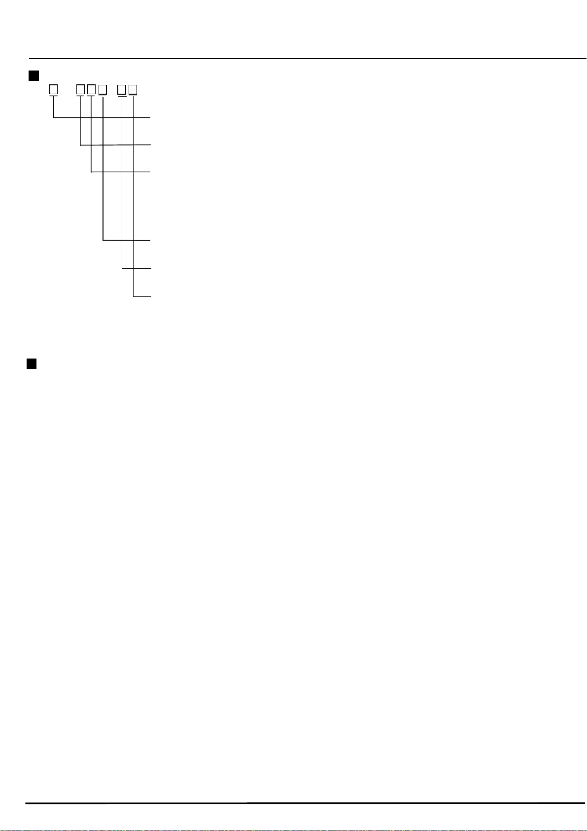
MODELS
AL37 P - - A
Input point
1: 1 point, 2: 2 points, 3: 3 points, 4: 4points
Communications interface (option)
N: None, A: RS-422A, R: RS-232C, S: RS-485
Alarm output/remote contacts (option)
0: None
1: 6 (MOS relay) alarm outputs + remote contacts
2: 6 (mechanical relay “c” contact) outputs + remote contact (*see note)
A: 6 (mechanical relay "a" contact) outputs + remote contacts
Others (option)
0: None, 1: Printing format
Math function (Option)
0: None, 1: Basic, 2: Totalizing/flow correction, 3: Basic + Totalizing/flow correction
Door/case (option)
0: Standard, 1: With handle and rubber stands (*see note), 2: Die-case door,
3: With handle and rubber stands + Die-case door (*see note)
Note : Not conforming to CE, UL and CSA
INPUT SPECIFICATIONS
Number of measuring points: 1 to 4 points
Input signals:
Universal input
DC voltage, thermocouple, resistance thermometer
DC current (by adding shunt resistors)
Contacts input [remote contacts input (option – up to 4
points) for operation printing for inputs]
Range setup:
Programming of input types and ranges by keys
Scale setup:
Programming of maximum values, minimum values
and engineering units by keys
Accuracy rating: Refer to the table of inputs.
Temperature drift:
±0.01% of full scale/ºC (converted into reference
ranges)
Measuring cycle: About 100msec
Reference junction compensation accuracy:
K, E, J, T, N, Platinel lI ……….. ±0.5ºC or less
R, S, NiMo-Ni, CR-AuFe, W-Wre26, WRe5-WRe26
U, L …………………………… ±1.0ºC or less
(At the measurement higher than 0ºC, the above
errors are added to the accuracy ratings for an
internal reference junction compensation.)
Input resolution:
About 1/56000 (converted into reference ranges)
Burnout:
For thermocouple inputs and resistance thermomete
inputs
Up-scale burnout, down-scale burnout or burnou
disabled is selectable for each input.
Allowable signal source resistance:
Thermocouple inputs, DC voltage inputs ...
1kΩ (burnout disabled) or less
Resistance thermometer inputs ...
10Ω or less (per wire)
(same resistance for 3 wires)
Input resistance:
Thermocouple inputs, DC voltage inputs … about 8MΩ
DC voltage more than ±5 V … about 1MΩ
Maximum input voltage:
Thermocouple inputs, DC voltage inputs (for ±2VDC
range or lower) …
±10VDC or less
DC voltage inputs (for ±5VDC range or higher) …
±60VDC or less
Resistance thermometer inputs ...
±6VDC or less
Input correction:
Zero/span correction and shift correction for each
channel
Input first-order lag filter:
Time constant of 0 and 1 to 10 seconds can be set in
each channel.
Common mode rejection ratio:
140dB or more (50/60Hz)
Series mode rejection ratio:
50dB or more (50/60Hz)
Terminal board:
Detachable type, removable for wirings
2
Page 3

t
t
f
r
A
r
y
PRINTING SPECIFICATIONS
Printing deadband: 0.2% (of printing span)
Printing system:
Analog tracing … Disposal cartridge pen
Digital printing … Plotter pen
Step response: 1 second or shorter (90% response)
Printing color:
Analog tracing … 1
3
Digital printing … purple (Printing are limited by chart
Periodic printing, Digital data printing (analog tracing
continuance/ interruption), Date and time printing (a
power on, every hour), Chart speed printing, Scale,
unit and tag printing, Alarm activation/reset printing,
Programming change mark, POC (pen offse
correction) mark, List printing
Printing ON/OFF function:
ON or OFF programming can be set in the following
printings.
Date and time, Scale, unit and tag, Chart speed, Alarm
activation/reset, POC mark
Chart: Fan-fold type, effective width 100mm, total width
114mm, total length 10m
Chart speed:
1 to 600 mm/hr, 1 to 200mm/min (Default: 20mm/hr)
Chart speed accuracy:
±0.1% or less (to the reference of time line o
chart-feeding longer than 1000mm)
Skip function:
No display or printing of channels of which ranges are
not programmed.
Printing correction:
Zero and span correction of analog tracing
Phase synchronizing correction:
Time axis pen offset correction (POC)
Subtract printing:
Printing of difference between two channels o
between a channel and a referenced value
(programmed value)
Message printing:
Letters pre-programmed are printed by a key or a
remote contacts (option).
5 kinds of message (time + message of maximum 15
letters)
Pen-lift function:
By RECORD OFF key, all pens are lifted up
simultaneously.
t the power OFF, the pen status just before the powe
OFF is kept.
st
pen red, 2nd pen green,
rd
pen blue, 4th pen brown
speed.)
DISPLAY SPECIFICATIONS
Analog indication:
100mm bargraph per each input point (51 segments,
Same color as analog tracing is indicated at each 5
segments.)
Digital display:
16 segments LCD 1 digit, character height 7.5mm,
orange
7 segments LCD 20 digits, character height 6.5mm,
white
-9999 to 99999 [optional decimal place, with cursor (b
each analog tracing color)]
Display items:
Simultaneous display of 4-channel measured values,
hour/minute, chart speed and alarm activated channel
Status display:
Printing status, key lock, alarm-activation, chart end,
fail and pen offset correction
ALARM SPECIFICATIONS
Alarm display:
"ALARM" illumination, flashing of measured value at an
alarm-activated channel and alarm type
Alarm types:
Absolut e val u e al a r m, di ffe r e nti a l al a rm , ra t e -of - ch an ge
alarm, absolute value/standby alarm and
differential/standby alarm, each 2 levels
Alarm programming:
Individual programming for each channel
Maximum 4 levels/channel
Alarm deadband:
0.1 to 9.9% of scale programming range (Default: 0.1%)
Alarm output: Option (Refer to the list of options.)
PROGRAMMING/OPERATION
Programming parameters:
Time, chart speed, periodic data printing, ranges,
scales, engineering units, tags, alarms, burnout,
subtract printing, ºC/ ºF, password
(Options: Communications, printing format, message
printing, math function)
Printing operation:
RECORD ON/OFF.. Printing on/off
FEED …………… Fast-feeding of chart
LIST …………… List printing
DATA PRINT ……… Digital data printing
Pen replacement:
Pens are replaced by moving them in the pen
replacement mode.
Engineering port:
By using the engineering software package (PASS), all
parameters can be programmed by a personal
computer.
3
Page 4

A
r
r
t
r
r
y
t
r
GENERAL SPECIFICATIONS
Rated power voltage:
100 to 240VAC, 50/60Hz
Power consumption: Maximum 60VA
Environmental conditions:
• Reference operating condition ...
Ambient temperature/humidity range:
21 to 25°C, 45 to 65%RH
• Normal operating condition …
Ambient temperature/humidity range:
0 to 50°C, 20 to 80%RH
Power voltage: 90 to 264VAC
Power frequency: 50/60Hz ± 2%
Attitude: Left/right 0 to 10°, Forward tilting 0°,
Ambient temperature/humidity range:
-20 to 60°C, 5 to 90%RH
(No dew condensation)
Vibration: 10 to 60Hz, 4.9m/s
Impact: Less than 392m/s2 or less
• Storage condition …
Ambient temperature/humidity range:
-20 to 60°C, 5 to 90%RH
(No dew condensation)
Insulation resistance:
More than 20MΩ at 500VDC
Note: Primary terminals:
Secondary terminals:
Power voltage: 100VAC ± 1%
Power frequency: 50/60Hz ± 0.5%
Warm-up time: More than 30 minutes
• Transportation condition (at the packed condition on
shipment from our factory) …
Between secondary terminals and protective conducto
terminal …
More than 20MΩ at 500VDC
Between primary terminals and protective conducto
terminal ...
More than 20MΩ at 500VDC
Between primary terminals and secondary terminals ...
Between alarm terminals (mechanical relay contact “c”)
and other secondary terminals ...
More than 20MΩ at 500VDC
ttitude: Left/right 0°, Forward tilting 0°,
Backward tilting 0°
Backward tilting 0 to 30°
2
or less
Power (L, N), Alarm (MOS relay,
mechanical relay contact “a”)
Input, Alarm (mechanical relay contac
“c”), Remote contacts, Communications
Dielectric strength:
Between secondary terminals and protective conducto
terminal .……….. 1 minute at 500VAC
Between primary terminals and protective conducto
terminal .……….. 1 minute at 1500VAC
Between primary terminals and secondar
terminals .………………….. 1 minute at 2300VAC
Between alarm terminals (mechanical relay contact “c”)
and other secondary terminals ... 1 minute at 1000VAC
Note: Primary terminals:
Power (L, N), Alarm (MOS relay,
mechanical relay contact “a”)
Secondary terminals:
Input, Alarm (mechanical relay contac
“c”), Remote contacts, Communications
Power failure protection:
Programmed parameters stored into EEPROM
memory
Clock circuit and POC data sustained for minimum 8
years by a lithium battery (at the operation more than 8
hours/day)
Case assembly material:
Door … ABS resin (frame) with glass
Enclosure ... Steel
Color: Door … Black (frame - equivalent to Munsell N3.0)
Enclosure ….. Gray (equivalent to Munsell N7.0)
ounting: Panel mounting
Weight: About 4.0kg (full options)
lock accuracy:
Within ±2 minutes per 30-day (under reference
operating conditions, except errors by turning powe
supply on or off
Power voltage fluctuation:
Indication fluctuation 0.1% or less (converted into
reference ranges) at 90 to 264VAC
isplay startup characteristics: Indication difference between
0 minutes and 4 hours after power on is 0.1% or less.
converted into reference ranges except resistance
hermometer input)
erminal screws:
Power terminals .……………….. M4.0
Protective conductor terminals.. M4.0
Measuring input terminals .……… M3.5
Alarm terminals ……………. M3.5
Remote contact terminals .…….. M3.5
Communications terminals ……. M3.5
Chart illumination: By CFL
STANDARDS
CE: EN61326 A1 Class A
EN61010-1 A2
UL: UL3111-1 (approval pending)
CSA (C-UL): C22.2, No.1010 (approval pending)
Front protection: Conforming to IEC529 IP54
NEMA250 type 13 (approval pending)
4
Page 5

INPUT
Input Measuring Reference Accuracy Display Input Measuring Reference Accuracy Display
signals Ranges ranges ratings resolutions signals Ranges ranges ratings resolutions
-13.8 to 13.8mV ±13.8mV 10µV W-WRe26 0 to 2315ºC ±69.0mV ±0.15% ± 1 digit 1ºC
-27.6 to 27.6mV ±27.6mV 10µV WRe5-WRe26 0 to 2315ºC ±69.0mV 1ºC
-200 to 200mV ±200mV 100µV
PtRh40-PtRh20
0to 1888ºC ±13.8mV 1ºC
-500 to 500mV ±500mV 100µV -50 to 290ºC ±13.8mV 0.1ºC
DC voltage
K
E
J
T
Thermocouple
R
S
B 0 to 1820ºC ±13.8mV
N
-2 to 2V ±2V 1mV -50 to 600ºC ±27.6mV 0.1ºC
-5 to 5V ±5V 1mV
-10 to 10V ±10V 10mV CR-AuFe 0 to 280K ±13.8mV
-20 to 20V ±20V 10mV 0 to 350ºC ±13.8mV 0.1ºC
-50 to 50V ±50V
-200 to 300ºC ±13.8mV 0.1ºC
-200 to 600ºC ±27.6mV 0.1ºC -200 to 250ºC ±13.8mV 0.1ºC
-200 to 1370ºC ±69.0mV 1ºC -200 to 500ºC ±27.6mV 0.1ºC
-200 to 200ºC ±13.8mV 0.1ºC
-200 to 350ºC ±27.6mV 0.1ºC -200 to 250ºC ±13.8mV 0.1ºC
-200 to 900ºC ±69.0mV 1ºC -200 to 500ºC ±27.6mV 0.1ºC
-200 to 250ºC ±13.8mV 0.1ºC
-200 to 500ºC ±27.6mV 0.1ºC -140 to 150ºC
-200 to 1200ºC ±69.0mV 1ºC -200 to 300ºC
-200 to 250ºC ±13.8mV 0.1ºC
-200 to 400ºC ±27.6mV 0.1ºC -140 to 150ºC
0 to 1200ºC ±13.8mV 1ºC -200 to 300ºC
0 to 1760ºC ±27.6mV 1ºC
0 to 1300ºC ±13.8mV 1ºC -140 to 150ºC
0 to
1760ºC ±27.6mV 1ºC -200 to 300ºC
-200 to 400ºC ±13.8mV 0.1ºC Pt50 -200 to 649ºC
-200 to 750ºC ±27.6mV 0.1ºC
-200 to
1300ºC ±69.0mV
±0.1% ± 1 digit
±0.1% ± 1 digit
±0.15% ± 1 digit
NiMo-Ni
-50 to 1310ºC ±69.0mV 1ºC
10mV 0 to 650ºC ±27.6mV 0.1ºC
1ºC
1ºC
Platinel II
Thermocouple
U
L
Pt100 (1)
Pt100 (2)
Resistance thermometer
JPt100
Pt-Co 4 to 374K
0 to 1390ºC ±69.0mV 1ºC
-200 to 600ºC ±69.0mV
-200 to 900ºC ±69.0mV
-200 to 850ºC
-200 to 649ºC
-200 to 649ºC
160Ω
220Ω
400Ω
160Ω
220Ω
400Ω
160Ω
220Ω
400Ω
220Ω
220Ω
±0.2% ± 1 digit
±0.15% ± 1 digit
±0.1% ± 1 digit
±0.15% ± 1 digit 0.1ºC
±0.1% ± 1 digit
±0.15% ± 1 digit 0.1ºC
±0.1% ± 1 digit
±0.15% ± 1 digit 0.1ºC
±0.1% ± 1 digit
±0.1% ± 1 digit 0.1ºC
±0.15% ± 1 digit 0.1K
0.1K
0.1ºC
1ºC
0.1ºC
0.1ºC
0.1ºC
0.1ºC
0.1ºC
0.1ºC
Note) Accuracy ratings are of measuring ranges at reference operation conditions. The reference junction compensation accuracy is not
included with the accuracy ratings of thermocouple inputs.
The indication equi val ent t o 200µV or 5ºC may vary under the t est environment requested by EMC directive.
K, E, J, T, R, S, B, N: IEC584, JIS C1602-1995
U(Cu-CuNi), L (Fe-CuNi): DIN43710
W-WRe26, Wre5-WRe26, Platinel II, CR-AuFe, PtRh40-PtRh20, NiMo-Ni: ASTM V ol.14.03
Pt100(1): IEC751(1995), JIS C1604-1997
Pt100(2): IEC751(1983), JIS C1604-1989, JIS C1606-1989
JPt100: JIS C1604-1981, JIS C1606-1986
5
Page 6

r
OPTIONS
Options Explanations
Three kinds of output (alarm, FAIL and
chart-end) are possible.
Output: 6 points
Maximum contact rating:
MOS relay output …
Alarm
output
Alarm output + remote contacts
Remote
contacts
Printing
*
format
Communications
interface
Basic
mathematics
Totalizing/
flow
correction
Handle and
rubber stands
Aluminum
die-cast door
16m chart Total length of 15.6m
ACCESSORIES (Separate purchase is required.)
Article Content
Shunt resistor for
current input
Transmitter power
supply unit
RZ-TPS01
240V (AC, DC), 50mA (AC, DC),
resistive load
“a” contact mechanical relay output …
240V AC 0.2A, resistive load
“c” contact mechanical relay output …
240V AC 0.2A, resistive load
(“c” contact: not conforming to CE, UL
and CSA.)
By 4-point contact input (2-point
common) signal, the following 6 kinds of
operation are selectable.
Chart speed 3-speed/chart stop, digital
data print, list print, 4-point operation
printing (printing of contact ON/OFF
status), totalizing start/stop, 5-kind of
message printing
Zone printing …
Printing area is divided into 2 zones
Compressed/ expanded printing …
A part of printing area of each channel is
printing compressed or ex p anded.
Automatic range-shift printing …
Printing range is automatically changed
into a new printing area in the event of
over-range or under-range
3 kinds of RS-232C, RS-422A, RS-485 (to
be specified)
Two kinds of protocol, MODBUS and
private, are built-in.
The following math-function can be
executed in time order or between
channels..
Arithmetic, Absolute value, Square root,
Logarithm, Natural Logarithm, Exponential,
Maximum, Minimum, Average,
Temperature/humidity
Totalizing of measured data and calculated
results and correction of flow by pressure,
temperature, etc.
Handle and rubber stands are mounted for
easy carrying (not conforming to CE, UL
and CSA.)
Case for horizontal high-density panel
installation and aluminum die-cast door
250Ω (for 20mA) and 100Ω (for 50mA)
Power supply unit for transmitters
The unit is mounted on backside of
recorder.
Data acquisition software package "KIDS"
The "KIDS" is a software package for storing data being
measured by AL3000 and AH3000 series recorders and fo
replaying of the stored data.
Main function and features:
• Data processing: Up to 5 sets (max. 100 channels)
Real-time data, real-time trend, historical data, historical
trend and daily report
• Communications interfaces:RS-232C, RS-422A or RS-485
• Stored data: Can be exported to Microsoft Excel, Lotus
1-2-3 and other application software.
• OS: Windows 95/98, Windows NT4.0
Engineering software package "PASS"
The "PASS" is a software package, through a
communications interface (optional) or a configuration port,
for programming parameters of AL3000 and AH3000 series
recorders by a personal computer.
Main functions and features
• Input parameters:
Ranges, scales, tags, engineering units, alarms, burnout
• Printing parameters:
Chart speed, data interval, subtract printing, zone printing,
compressed/expanded printing, automatic range-shift
printing
• Operation: Message printing
• Others:
Clock setting, temperature units (ºC, ºF), alarm
communications specification (for programming through a
configuration port only)
• OS: Windows95/98, WindowsNT 4.0
DIMENSIONS
274mm for adding alarm output of MOS relay or “c” contact
mechanical relay, and communications interface
* 285mm for adding “a” contact mechanical relay
deadband,
Panel cutout and minimum clearance for installation
32-8, KUMANO-CHO, ITABASHI-KU, TOKYO 173-8632
PHONE: +81-3-3956-2171
FAX: +81-3-3956-0915
E-mail: inter@chino.co.jp
Website: http://www.chino.co.jp
Specifications subject to change without notice. Original 2001.5
 Loading...