

Page 1
INST.№ INE-288C
OPTIONS
[MATH FUNCTION]
[TOTALIZER]
[FLOW CORRECTION]
FOR AL/AH3000 SERIES
HYBRID RECORDER
Retain this manual apart from the
instrument and in an easily accessible.
Please make sure that this manual is handed to the final user of the instrument.
Page 2

TABLE OF CONTENTS
Introduction
1. Separate manuals
2. ‘Data communications input’ by keys
[1] Math functions
1. Types of math functions
2. Programming
2.1 Printing channel for computed result 3
2.2 Printing range 3
2.3 Decimal place for display and printing 3
2.4 Computation of maximum, minimum and average values 3
3. Programming flow chart
3.1 Types of math function and their flow chart 4
3.2 Square root, logarithm, exponential, absolute value and data communications input 5
3.3 Arithmetic computation 1 6
3.4 Arithmetic computation 2 8
3.5 Computation of maximum, minimum and average values 10
3.6 Computation of temperature/humidity 12
[2] Totalizing
1. Math expression for totalizing computation
2. Programming
2.1 Resetting of totalizing computation 14
2.2 Overflow of totalized value 14
2.3 Operation at power failure recovery 15
2.4 Interval time 15
2.5 Starting time of totalizing computation 15
2.6 Printing range 15
2.7 Decimal place for display and printing 15
3. Programming flow chart
[3] Flow correction
1. Correction computation types and math expressions
1.1 Flow correction computation 1 (FloW1) 18
1.2 Flow correction computation 2 (FloW2) 18
1.3 Flow correction computation 3 (FloW3) 18
1.4 Flow correction computation 4 (FloW3) 19
1.5 Flow correction computation 5 (FloW5) 19
1.6 Flow correction computation 6 (FloW6) 19
1.7 Flow correction computation 7 (FloW7) 19
2. Programming
2.1 Printing range 20
2.2 Decimal place for display and printing 20
2.3 Abnormal data 20
3. Programming flow chart
[4] List printing
[Appendix] Conversion table for temperature/humidity computation
1
1
1
1
1
3
4
14
14
14
16
18
18
20
22
24
25
Page 3
Introduction
This manual is only for the optional specifications of ‘Math function’, ‘Totalizer’ and ‘Flow correction’ of AL3000
and AH3000 series hybrid recorders. For the standard functions and other optional specifications, please refer
the separate manuals.
1. Separate manuals
1) Standards
AL3000 series (Multi-point type)
AH3000 series (Multi-point type)
AL3000 series (Pen type)
AH3000 series (Pen type)
2) Option
Communications interface
[Note] - □ is the Revision No.
2. ‘Data communications input’ by keys
INE-270□
INE-271□
INE-308□
INE-272□
‘Data communications input’ can be programmed with keys when the ‘Math function’ (option) and
‘Communications interface’ (option) are combined. However, for the option of ‘Communications interface’, it is
programmed through communications only.
[1] Math functions
The measured data of each channel can be computed and their results are displayed and printed.
The alarm setpoints in the channel Nos. for computed results are programmed for the computed values.
1. Types of math functions
TYPE MATH EXPRESSION SET VALUE * 1
1. non (no computation)
2. mUL
(Arithmetical
computation 1)
3. diV * 2
(Arithmetical
computation 2)
Ax + By + Cxy +D
A, B, C, D : Constant
x, y : Measured values
Ax / y + B
A, B : Constant
x,y : Measured values
- -
• Channel No. for computed result
• Constant (A, B, C, D)
• Channel No. for measured values (x, y)
• Channel No. for computed result
• Constant (A, B)
• Channel No. for measured values (x, y).
4. LoGE
(Natural Logarithm)
5. LoG10
(Logarithm)
6. PoWEr
(Exponential)
LOGex
x : Measured value
LOG10x
x : Measured value
x
e
x : Measured value
• Channel No. for measured value (x)
• (= Channel No. for computed result)
• Channel No. for measured value (x)
• (= Channel No. for computed result)
• Channel No. for measured value (x)
• (= Channel No. for computed result)
-1-
Page 4

7. root *
3
(Square root)
8. Humidity
(Humidity)
TYPE MATH EXPRESSION SET VALUE *
(SS-SZ)
RX-RZ
+SZ
RS-RZ
Rx : Voltage value of measuring input
R
: Maximum limit for range setting
s
: Minimum limit for range setting
R
z
S
: Maximum limit for scale setting
s
S
: Minimum limit for scale setting
z
• Channel No. for voltage value of
measuring input (R
(= Channel No. for computed result)
)
x
Measured values of dry bulb (x) and
wet bulb (y) and humidity is computed
by the relative humidity table.
• Channel No. for computed result
• Channel No. for measured values (x, y).
x, y : Measured values
1
9. Hi PEAk
(Maximam value)
10. Lo PEAk
(Minimum value)
11. AVErAGE
(Average value)
12. AbS *6
(Absolute value)
13. int *
14. Comm in *
4
(Totalizer)
5
(Data communications
input)
15-21 *6
FLoW1 to FLoW7
(Flow correction 1 to 7)
Maximum value of measured values
(x) during an interval
Minimum value of measured values (x)
during an interval
Average value of measured values (x)
• Channel No. for computed result
• Interval
• Starting time
• Channel No. for measured value (x)
during an interval
|x|
x : Measured value
• Channel No. for measured value (x)
• (= Channel No. for computed result)
This is only applicable for the “Totalizer” (option).
Refer to Section [2] for details.
Nil
[Only displayed for the
• ·Channel for data communications input
“communications interface” (option)]
This is only applicable for the “Flow correction” (option).
Refer to Section [3] for details.
*1 : Setting of printing rage is necessary for all math functions from 2 to 21.
*2 : When the measured value (y) is 0, the value (Ax) becomes as bellow.
if Ax>0 then OVER
if Ax=0 then 0
if Ax<0 then –OVER
*3 : The math expression shown in the right side is applied when the measuring input voltage (Rx) is 1% or more
of the setting range (Rs - Rz). When it is less than 1%, it becomes and is fixed to the minimum value of scale
setting (Sz).
*4 : Refer to Section 2 item 14 for the ‘Totalizer’ (option).
*5 : When the ‘Math-function’ (option) and ‘Communications Interface’ (option) are combined, the data
communications input can be set by keys.
*6 : Only pen type.
-2-
Page 5

2. Programming
2.1 Printing channel for computed result
1) Math functions of which computed results are only printed in the channels Nos. of measured value
The computed result by the math functions of square root, natural logarithm, logarithm, absolute value, and
exponential is only printed in the channel No. of measured value (x). Therefore the measured value (x), which
these 5 math functions are applied to, cannot be printed.
2) Math functions of which computed results can be printed in any channels
The computed result by other math functions than the above 5 kinds can be printed in any channels including
the channel of measured value. However, if the channel of measured value is selected, the measured value
cannot be printed.
2.2 Printing range
The printing range of the channel for computed result is “Printing range” programmed by math function
programming, not by range programming.
2.3 Decimal place for display and printing
The decimal place is decided by “Printing range” programmed by math function programming. If the decimal
place differs in the maximum and minimum values, the fewer decimal places is effective.
2.4 Computation of maximum, minimum and average values
1) Resetting of computation
The computation is automatically reset after the programmed interval time. Accordingly maximum, minimum
and average values in each interval time are computed.
2) Operation at power failure recovery
1. If the power is recovered in the programmed interval time, the computation continues.
2. If the power is not recovered in the programmed interval time, the computation is canceled and starts again
from the recovery time.
3. The judgment of power failure is within 24 hours. If the power failure continues longer than 24 hours, the
computation is canceled irrespective the recovery time and starts again from the recovery time.
3) Starting time of computation
The starting time is only valid for the first operation after its setting. The computation starts from the starting
time.
-3-
Page 6

3. Programming flow chart
3.1 Types of math function and their flow charts
The programming flow chart differs on the type of math function.
Type of math function Item No. (Page)
MuL (Arithmetic computation 1) 3.3 (page 6)
diV (Arithmetic computation 2) 3.4 (page 8)
LoGE (Natural logarithm) 3.2 (page 5)
LoG10 (Logarithm) 3.2 (page 5)
PoWER (Exponential) 3.2 (page 5)
Root (Square root) 3.2 (page 5)
Humidity (Humidity) 3.6 (page 12)
Hi PEAk (Maximum value) 3.5 (page 10)
Lo PEAk (Minimum value) 3.5 (page 10)
AVErAGE (Average value) 3.5 (page 10)
AbS (Absolute value) 3.2 (page 5)
Comm in (Data communications port) 3.2 (page 5)
-4-
Page 7
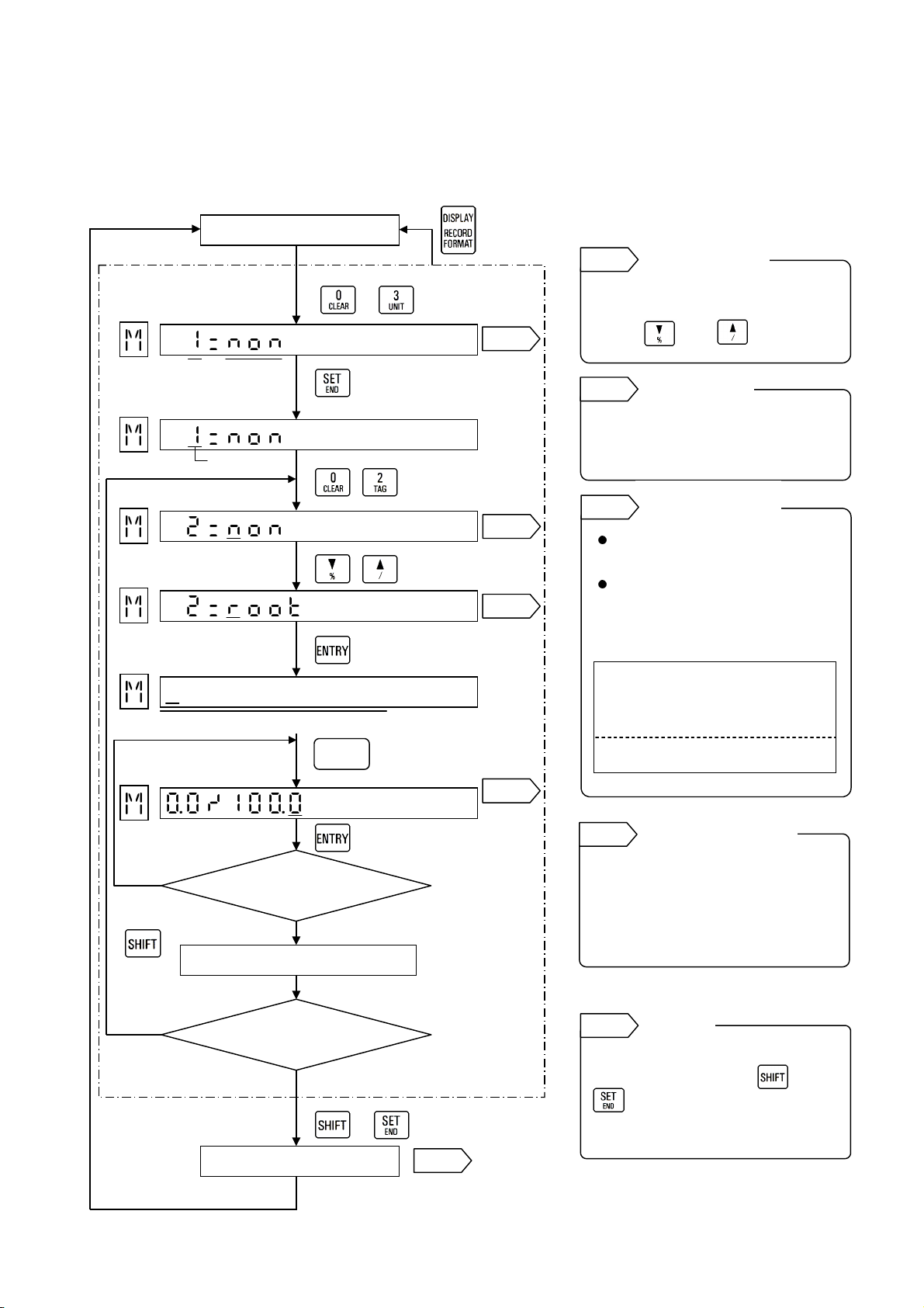
3.2 Square root, logarithm, exponential, absolute value and data
yp
f
communications input
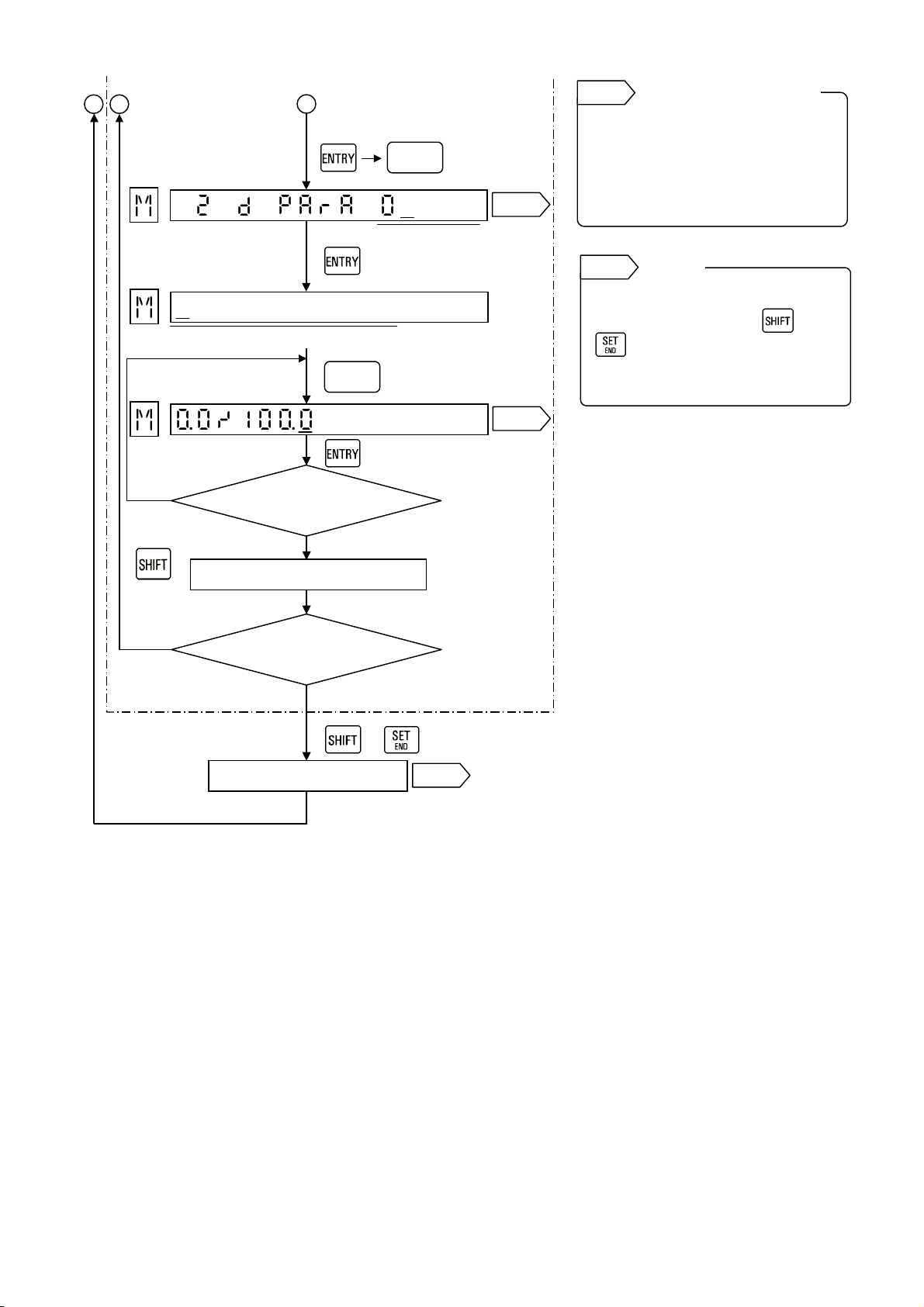
(Ex.) To execute the square root computation for the measured value of Channel 2 and program the printing
range to 0.0 to 100.0
[Checking of
math function type]
Channel
[To be ready
for programming]
[Programming channel]
[Selecting Square root]
[To printing range
programming]
[Programming printing
range setting]
YES
Any key
other than
YES
Operation screen
( + )
Math func-
e
tion t
Cursor
Printing range (Min to Max)
Error message appears?
NO
Temporarily stored
Programming other channels?
NO
Stored
3 sec or longer
Various
keys
+
Ref. 5
Ref. 1
Ref. 2
Ref. 3
Ref. 4
Ref. 1
You can check the math function
type of other channels.
Press or to change
channels.
Ref. 2
In AH3000 series multi-point type, a
channel is programmed by two digits
(06/12/24).
Ref. 3
Ref. 4
Program the values within 5 digits
including a sign. The remaining
digits on the right side should be
kept blank. For the initial
programming, all digits are blank.
Ref. 5
Store “temporarily stored”
parameters by pressing and
simultaneously.
If not, the parameters programmed
earlier remain.
Checking of
other channels
Channel digit
Math functions by
this flow chart
This flow chart is applied to the
following 3 math functions.
When the communications
interface is added, the data
communications input can be set
with keys.
LoGE : Natural logarithm
Log10 : Logarithm
PoWEr : Exponential
AbS : Absolute value
Commin
: Data communications
input
Programming range o
max. and min. values
Storing
.
-5-
Page 8
3.3 Arithmetic computation 1
(Ex.) Ax + By + Cxy + D: To multiply the measured value ‘x’ of Channel 2 by 2 and print its result on Channel 2
A = 2, B = C = D = 0, x = Channel 2, y = not used, Printing range = 0.0 to 100.0
[Checking of
math function type]
Recording
Channel
[To be ready for
programming]
[Programming channel]
[Selecting Arithmetic
operation 1]
[Programming ‘x’ channel]
[Programming ‘y’ channel]
[Programming Constant A]
[Programming Constant B]
[Programming Constant C]
B C
Operation screen
( + )
Math func-
tion type
Cursor
x channel
A
y channel
Various
keys
Constant A
Various
keys
Constant B
Various
keys
Constant C
3 sec or longer
Ref. 1
Ref. 2
Ref. 3
Ref. 4
Ref. 4
Ref. 5
Ref. 5
Ref. 5
Ref. 1
You can check the math function
type of other channels.
Press or to change
channels.
Ref. 2
In AH3000 series multi-point type, a
channel is programmed by two digits
(06/12/24).
Ref. 3
This flow chart is only applied to
Arithmetic computation 1 (mUL).
Ref. 4
1. Not-used channel
2. For the initial programming, both
Ref. 5
1. Not-used constants
2. Programming of constants
Checking of
other channels
Channel digit
Math functions by
this flow chart
‘x’ and ‘y’ channels
If the measured value of ‘x’
channel or ‘y’ channel is not used,
make sure to program any
channel number to the channel
not used as a dummy input. (No
programming of the channel not
used will become an error.) Then
program the appropriate
constants to ‘0’.
‘x’ and ‘y’ channels are blank.
Constants of A, B, C and D
For the not-used constant,
program it to ‘0’.
(1) 5 digits or less including a
sign
(2) Down to three decimal places
Ex.□□.□□□
.
-6-
Page 9
C
A
f
B
[Programming Constant D]
[To printing range
programming]
Printing range (Min to Max)
[Programming
printing range]
Various
keys
Constant D
Various
keys
Ref. 6
Program the values within 5 digits
including a sign. The remaining
digits on the right side should be
kept blank. For the initial
Ref. 5
Ref. 6
programming, all digits are blank.
Ref. 7
Store “temporarily stored”
parameters by pressing and
parameters programmed earlier
remain.
Programming range o
max. and min. values
Storing
simultaneously. If not, the
YES
Any key
other than
YES
Error message appears?
NO
Temporarily stored
Programming other channels?
NO
+
Stored
Ref. 7
-7-
Page 10

3.4 Arithmetic computation 2
A
(Ex.) Ax / y + B: To divide the measured value ‘x’ of Channel 2 by the measured value ‘y’ of Channel 1 and print
its result on Channel 2
A = 1.0, B = 0, x = Channel 2, y =1, Printing range = 0.0 to 100.0
[Checking of
math function type]
C
Recording
Channel
[To be ready for
programming]
[Programming channel]
[Selecting Arithmetic
operation 2]
[Programming ‘x’ channel]
[Programming ‘y’ channel]
[[Programming Constant A]
[Programming Constant B]
[To printing range
programming]
B
Operation screen
( + )
Math func-
tion type
Cursor
x channel
Printing range (Min to Max)
y channel
3 sec or longer
Various
keys
Constant A
Various
keys
Constant B
Ref. 1
You can check the math function
type of other channels.
Ref. 1
Ref. 2
Ref. 3
Ref. 4
Ref. 4
Ref. 5
Ref. 5
Press or to change
channels.
Ref. 2
In AH3000 series multi-point type, a
channel is programmed by two digits
(06/12/24).
Ref. 3
This flow chart is only applied to
Arithmetic computation 2 (diV).
Ref. 4
For the initial programming, both ‘x’
and ‘y’ channels are blank.
Ref. 5
1. Not-used constants
2. Programming of constants
Checking of
other channels
Channel digit
Math functions by
this flow chart
‘x’ and ‘y’ channels
Constants of A and B
For the not-used constant (B),
program it to ‘0’.
(1) 5 digits or less including a
sign
(2) Down to three decimal places
Ex.□□.□□□
.
-8-
Page 11
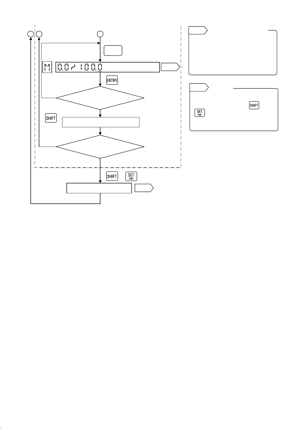
B
A
f
C
[Programming
printing range]
Any key
other than
YES
Various
keys
Error message appears?
NO
Temporarily stored
Ref. 6
Ref. 6
Program the values within 5 digits
including a sign. The remaining
digits on the right side should be
kept blank. For the initial
programming, all digits are blank.
Ref. 7
Store “temporarily stored”
parametersby pressing and
simultaneously. If not, the
parameters programmed earlier
remain.
Programming range o
max. and min. values
Storing
YES
Programming other channels?
NO
+
Stored
Ref. 7
-9-
Page 12

3.5 Computation of maximum, minimum and average values
A
e
e
(Ex.: Maximum value) To print, on Channel 3, the maximum value in the measured value of Channel 2
A (Interval) = 30 min., B (Start time) = 08:00 am, Printing range = 0.0 to 100.0
[Checking of
math function type]
Recording
Channel
[To be ready for
programming]
[Programming printing
channel]
[Selecting Maximum]
[Programming
measuring channel]
[Programming interval time]
[Programming starting time]
[To printing range
programming]
B C
Operation screen
Cursor
Printing range (Min to Max)
( + )
Math func-
tion type
Measuring channel
Various
keys
Interval
Various
keys
Start time
3 sec or longer
Ref. 1
Ref. 2
Ref. 3
Ref. 4
Ref. 5
Ref. 6
Ref. 1
You can check the math function
type of other channels.
Press or to change
channels.
Ref. 2
In AH3000 series multi-point type, a
channel is programmed by two digits
(06/12/24).
Ref. 3
This flow chart is applied to the
following 3 math functions.
Ref. 4
For the initial programming, the
measuring channel is blank.
Ref. 5
00:01 to 24:00
Ref. 6
00:00 to 23:59
Checking of
other channels
Channel digit
Math functions by
this flow chart
H i P E A k : Maximum value
L o P E A k : Minimum value
AVE r AG E : Average value
Measuring channel
Programming rang
of interval
Programming rang
of start time
.
-10-
Page 13

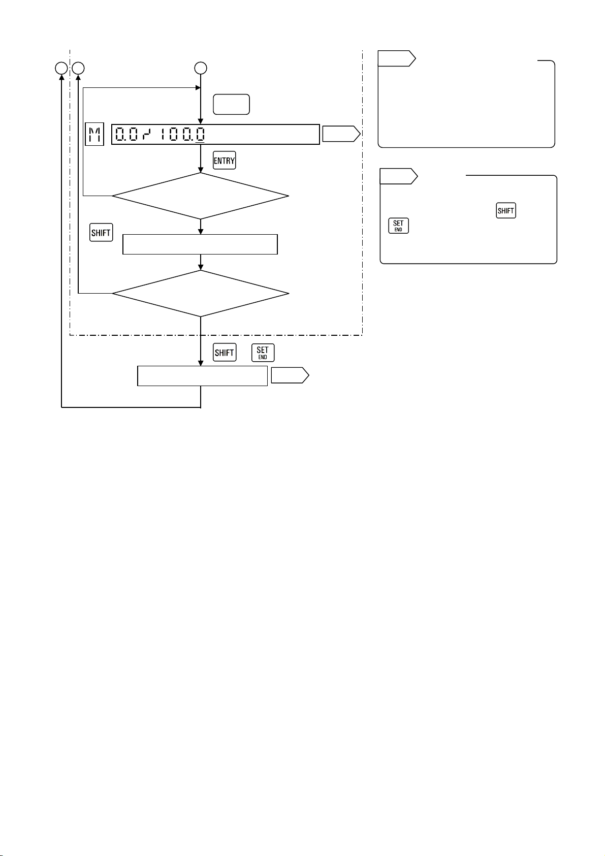
B
A
f
C
[Programming
printing range]
Any key
other than
YES
Various
keys
Error message appears?
NO
Temporarily stored
Ref. 7
Ref. 7
Program the values within 5 digits
including a sign. The remaining
digits on the right side should be
kept blank. For the initial
programming, all digits are blank.
Ref. 8
Store “temporarily stored”
parameters by pressing and
simultaneously. If not, the
parameters programmed earlier
remain.
Programming range o
max. and min. values
Storing
YES
Programming other channels?
NO
+
Stored
Ref. 8
-11-
Page 14

3.6 Computation of temperature/humidity
A
(Ex.) To print the humidity on Channel 2
Dry bulb (Temperature) = Channel 1, Wet bulb (Temperature) = Channel 2, Printing range = 0.0 to 100.0
[Checking of
math function type]
C
Recording
Channel
[To be ready for
programming]
[Programming printing
channel]
[Selecting Humidity]
[Programming Dry bulb
channel]
[Programming Wet bulb
channel]
[To printing range
programming]
Printing range (Min to Max)
B
Operation screen
( + )
Math func-
tion type
Cursor
Dry bulb channel
3 sec or longer
Wet bulb channel
Ref. 1
Ref. 2
Ref. 3
Ref. 4
Ref. 4
Ref. 1
You can check the math function
type of other channels.
Press or to change
channels.
Ref. 2
In AH3000 series multi-point type, a
channel is programmed by two digits
(06/12/24).
Ref. 3
This flow chart is only applied to
Humidity computation (HUmidity).
Ref. 4
For the initial programming, both dry
bulb and wet bulb channels are
blank.
Checking of
other channels
Channel digit
Math functions by
Dry and wet bulb channels
-12-
Page 15
C
f
B
other than
[Programming
printing range]
YES
Any key
A
Various
keys
Error message appears
NO
?
Temporarily stored
Ref. 6
Ref. 6
Program the values within 5 digits
including a sign. The remaining
digits on the right side should be
kept blank. For the initial
programming, all digits are blank.
Ref. 7
Store “temporarily stored”
parameters by pressing and
simultaneously. If not, the
parameters programmed earlier
remain.
Programming range o
max. and min. values
Storing
YES
Programming other channels
NO
+
Stored
?
Ref. 7
-13-
Page 16

[2] Totalizing
The measured data of each channel can be totalized and their results are displayed and printed.
The alarm setpoints in the channel Nos. for totalized results is programmed for the totalized values.
1. Math expression for totalizing computation
+ PV
(PV
n
INT
= INT
n
n-1
+
INT
: Totalized value T n : Measured time at this time
n
: Last totalized value T
INT
n-1
: Measured value at this time *1 Tbase : Time unit *2
PV
n
: Measured value at last time *1
PV
n-1
*1 : If the measured value exceeds the scale range, the minimum or maximum values of scale is taken
as the measured value.
*2 : This time unit is for the measured value. If the unit is in second, the value is 1. If it is in minute, the
value is 60. If it is in hour, the value is 3600. The unit is selected from second, minute or hour.
(Ex.) m3/min→60, m3/h→3600
Note) Measuring interval (T
n
- T
AL3000 Multi-point type (6-point input): approx. 5 seconds
AH3000 Multi-point type (6-point input): approx. 5 seconds
AH3000 Multi-point type (12-point input): approx. 10 seconds
AH3000 Multi-point type (24-point input): approx. 20 seconds
AL3000 pen type (1 to 4 point input): approx. 0.1 second
AH3000 pen type (1 to 4 point input): approx. 0.1 second
n-1
2
)
n-1
) × (T
- T
n
)
n-1
÷ Tbase
: Measured time at last time
n-1
2. Programming
2.1 Resetting of totalizing computation
1) Start and resetting of totalized value by remote contacts reset
When the optional remote contacts function is added, the totalizing computation can be started or the
totalized value can be reset by the remote contacts signal.
When the totalizing computation starts by the remote contacts reset, the totalized value is reset with
each programmed interval, after the start.
For multi-point type, the EX4 terminal in remote contacts terminals EX1 to EX4 is used for the resetting
of totalizing computation. The list printing is only executed by using this terminal when the totalizing
computation is not required. For details, refer to the separate standard manual.
2) Resetting of totalized value by the programmed intervals
The totalized value is automatically reset after the programmed interval time from the start of the
totalizing computation, and then restarts.
2.2 Overflow of totalized value
The maximum totalized value is limited to the maximum value of the printing range. When this totalized
value exceeds its limitation, the value is reset to 0 and then the totalizing computation continues.
-14-
Page 17

2.3 Operation at power failure recovery
1. If the power is recovered in the programmed interval time, the totalizing computation continues.
2. If the power is not recovered in the programmed interval time, the totalizing computation is canceled * and
starts again from the recovery time.
3. The judgment of power failure is within 24 hours. If the power failure continues longer than 24 hours, the
totalizing computation is canceled irrespective the recovery time and starts again from the recovery time.
* The totalizing computation is canceled and reset.
2.4 Interval time
The programming range of the interval time is 00:01 to 24:00. If the interval time is not required (in case of
resetting of the totalized value by the remote contacts reset), program it to 99:00.
2.5 Starting time of totalizing computation
The programming range of the starting time is 00:00 to 23:59. This starting time is only valid for the first operation
after its setting. The totalizing computation starts from the starting time. If the starting time is not required (starting
by the remote contacts signal), program it to 99:00.
2.6 Printing range
The printing range of the channel for totalized result is “Printing range” programmed by totalizing computation
programming, not by range programming.
2.7 Decimal place for display and printing
The decimal place is decided by “Printing range” programmed by totalizing computation programming. If
the decimal place differs in the maximum and minimum values, the fewer decimal places is effective.
-15-
Page 18
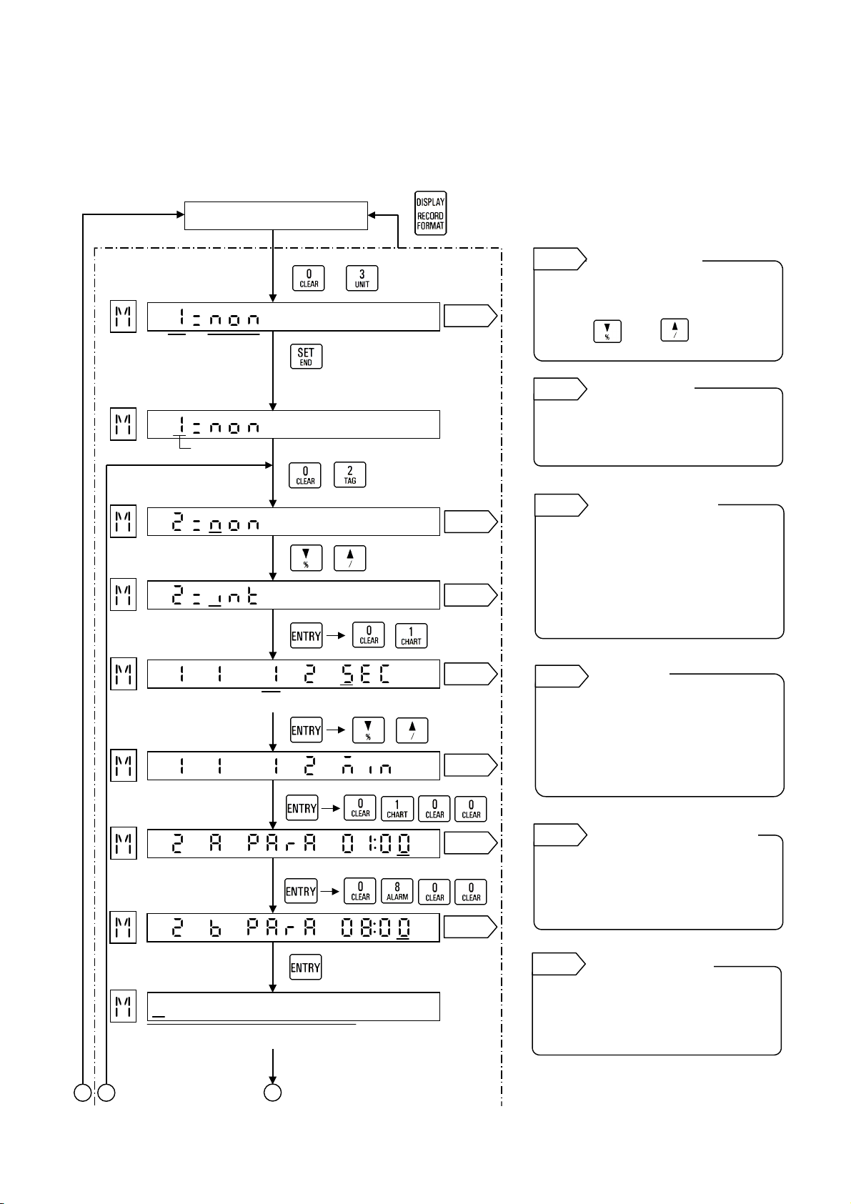
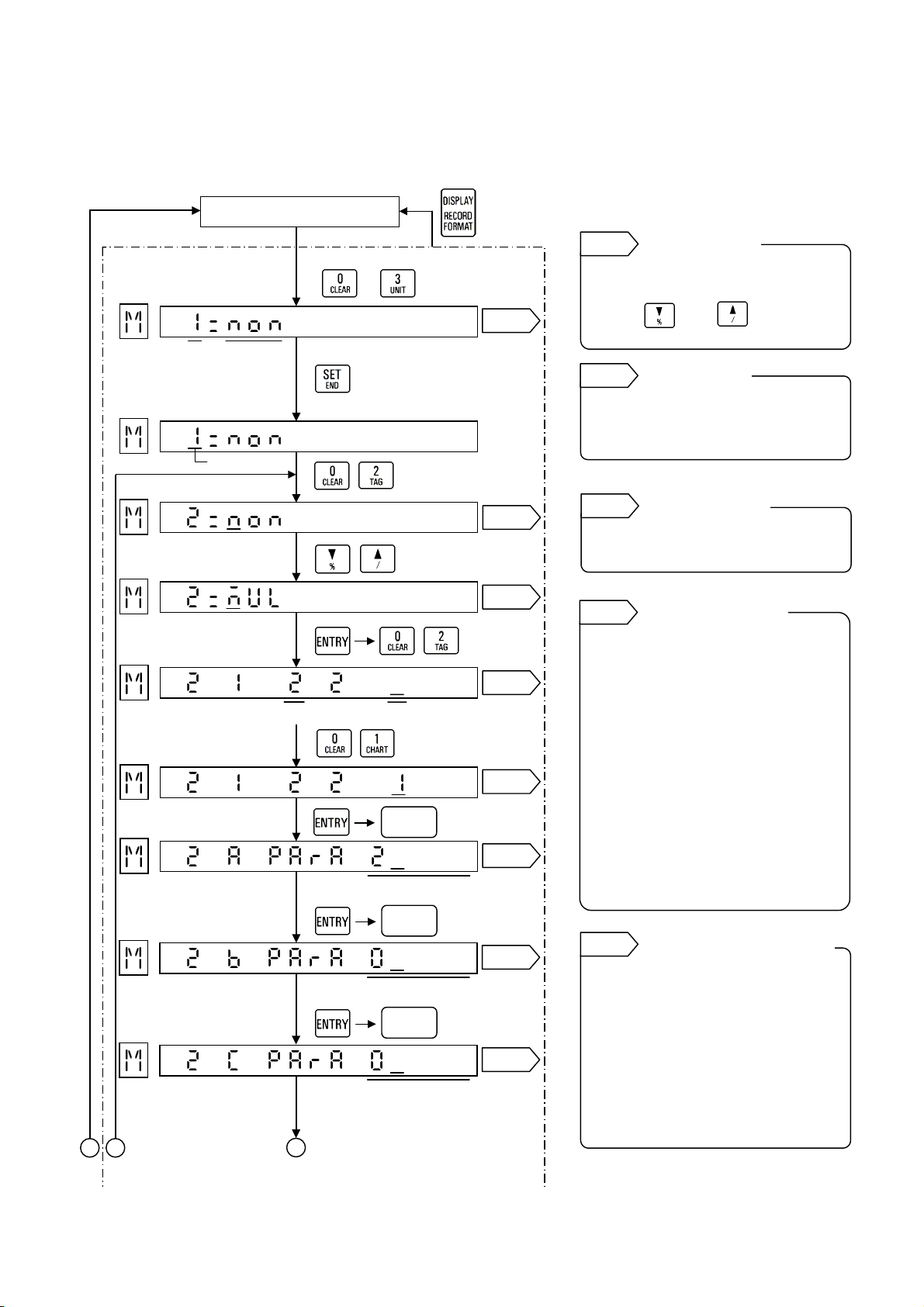
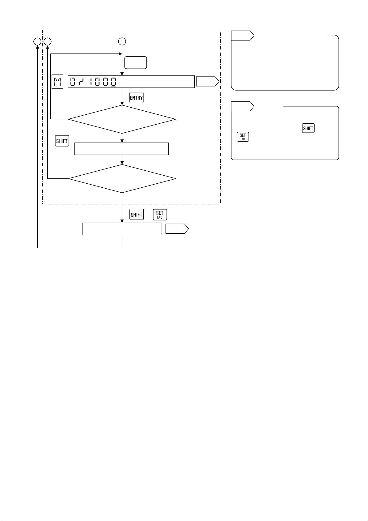
3. Programming flow chart
A
prog
g]
f
g
(Ex.) To execute the totalizing computation for measured value of Channel 1 and print its result on Channel 2
Time unit = min, Totalizing interval = 1 hour, Start time = 08:00 am
Printing range for totalized value = 0 to1000
[Checking of
math function type]
C
Recording
Channel
[To be ready
for programming]
Cursor
[Programming
printing channel]
[Selecting Totalization]
[Programming
measuring channel]
[Programming time unit]
[Programming interval time]
[Programming starting time]
[To printing range
rammin
B
Printing range (Min to Max)
Operation screen
( + )
Math func-
tion type
Measuring channel
3 sec or longer
Ref. 1
Ref. 2
Ref. 3
Ref. 2
Ref. 4
Ref. 5
Ref. 6
Ref. 1
You can check the math function
type of other channels.
Press or to change
channels.
Ref. 2
In AH3000 series multi-point type, a
channel is programmed by two digits
(06/12/24).
Ref. 3
This flow chart is only applied to
Totalizing computation (int).
For the combined option with math
functions, various items are
displayed.
Ref. 4
3 types of time unit (sec, min, and
hour) for measured value, are
available.
(Ex.) If m
Ref. 5
00:01 to 24:00
If the interval time is not required,
program it to 99:00.
Ref. 6
00:00 to 23:59
If the starting time is not required,
program it to 99:00.
Checking of
other channels
Channel digit
Math functions by
Time unit
3
/min is required, select
min.
Programming range o
Programming
e of start time
ran
-16-
Page 19
B C
A
[Programming
printing range]
YES
Any key
other than
Various
keys
Error message appears?
NO
Temporarily stored
Ref. 7
Ref. 7
Program the values within 5 digits
including a sign. The remaining
digits on the right side should be
kept blank. For the initial
programming, all digits are blank.
Ref. 8
Store “temporarily stored”
parameters by pressing and
simultaneously. If not, the
parameters programmed earlier
remain.
Programming range of
max. and min. values
Storing
YES
Programming other channels?
NO
+
Stored
Ref. 8
-17-
Page 20

[3] Flow correction
1.Correction computation types and math expressions
1.1 Flow correction computation 1 (FLoW1):
Volume correction of gas (ideal gas)
A • X • (E + B) / (C • (F + D)) A, B, C, D: Constants
E, F: Arbitrary channels
X: Measuring channel
(Basic formula)
P
T
Q
= Q i x
n
n
x
T
i
: Corrected result Q i : Volumetric flow rate at measurement condition of flow meter
Q
n
T
: Reference temperature T i : Temperature of measured fluid at measurement condition
n
: Reference pressure P i : Pressure of measured fluid at measurement condition
P
n
Z
: Compression coefficient of measured fluid at reference temperature (T n) and reference pressure (P n).
n
: Compression coefficient of measured fluid at measurement condition
Z
i
1.2 Flow correction computation 2 (FloW2):
Volume correction of liquid (excluding petroleum)
X • (1 - A • (E - B)) • (1 + C • (F - D)) A, B, C, D: Constants
(Basic formula)
= Q i • (1 - α • (T i - T n) • (1 + β • (P i - P n)
Q
n
Q n : Corrected result Q i :Volumetric flow rate at measurement condition of flow meter
: Reference temperature T i :Temperature of measured fluid at measurement condition
T
n
P n : Reference pressure P i :Pressure of measured fluid at measurement condition
α
: Cubic expansion coefficient of measured fluid
β
: Compressibility of measured fluid.
1.3 Flow correction computation 3 (FloW3):
E • exp (A • (F - B) + C • (F - B)
(Basic formula)
Q
= Q i • exp (- α
n
• t • (1.0 + 0.8α
t
KO K1
=
α
t
(ρ15)
Q
: Corrected result
n
: Volumetric flow rate at measurement condition of flow meter
Q
i
ρ15 : Density (15ºC) [kg/m
K0, K1 : Constants t : Temperature difference [ t = T
2
2
3
] α t : Thermal expansion coefficient at 15ºC [ºC-1]
Z
i
x
P n
Z i
n
E, F: Arbitrary channels
X: Measuring channel
Volume correction of liquid (petroleum)
) A, B, C: Constants
E, F: Arbitrary channels
• t)
t
x
ρ15
- 15] [ºC]
I
-18-
Page 21
1.4 Flow correction computation 4 (FloW3):
d
Square root computation of flow correction 1
A ・ X ・ (E+B)/C・ (F+D)
1.5 Flow correction computation 5 (FloW5):
Temperature/pressure correction of differential
pressure type flow meter (ideal gas)
A ・ X ・
(Basic formula)
Q
Q
: Corrected result Q f : Flow rate at measurement condition.
d
: Reference pressure T d : Reference temperature
P
d
P f : Pressure of measured fluid at measurement condition
: Temperature of measured fluid at measurement condition
T
f
(B・ E+C)/(D・ F+273.15)
= Q
d
f
P
f
•
d
P
•
T
T
f
1.6 Flow correction computation 6 (FloW6):
Temperature correction of differential pressure
type flow meter (ideal gas)
(A・ E+B/
C ・ F+D
1.7 Flow correction computation 7 (FloW7):
Pressure correction of differential pressure type
flow meter (ideal gas)
A, B, C, D: Constants
E, F: Arbitrary channels
X: Measuring channel
A, B, C, D: Constants
E, F: Arbitrary channels
X: Measuring channel
A, B, C, D: Constants
E, F: Arbitrary channels
(A•E+B)・
C ・ F+D
-19-
A, B, C, D: Constants
E, F: Arbitrary channels
Page 22

2. Programming
2.1 Printing range
The printing range of the channel for flow correction computed result is “Printing range” programmed by flow
correction computation programming, not by range programming.
2.2 Decimal place for display and printing
The decimal place is decided by “Printing range” programmed by flow correction computation programming. If
the decimal place differs in the maximum and minimum values, the fewer decimal places is effective.
2.3 Abnormal data
1. When the data of each channel is abnormal (over-range, under-range, burnout, without range
programming) or a denominator becomes zero (0), the flow correction computed result is treated as
under-range.
2. The flow rate input before correction is computed with the limitation at 0.
-20-
Page 23

memo
-21-
Page 24
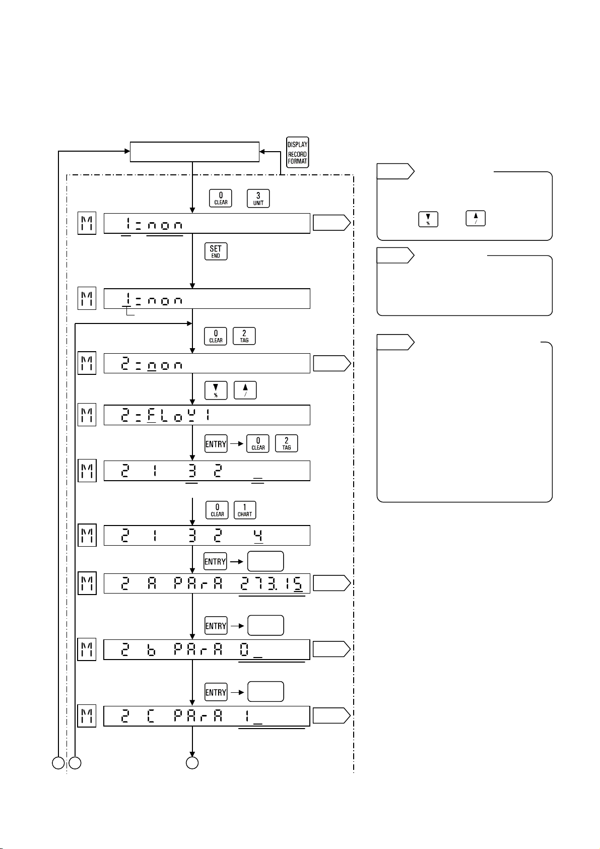
3. Programming flow chart
A
(Ex.) Flow correction 1: A • X • (E + B) / (C • (F + D))
A = D = 273.15, B = 0, C = 1, E = Channel 3 (pressure input)
F = Channel 4 (temperature input), X = Channel 2 (flow input), Printing range = 0.0 to 100.0
[Checking of
math function type]
Recording
Channel
[To be ready for
programming]
Cursor
[Programming
printing channel]
[Selecting Flow
correction computation1]
[Programming Channel E]
[Programming Channel F]
[Programming Constant A]
[Programming Constant B]
[Programming Constant C]
B C
Operation screen
( + )
Math func-
tion type
E channel
F channel
Various
keys
Constant A
Various
keys
Constant B
Various
keys
Constant C
3 sec or longer
Ref. 1
Ref. 2
Ref. 3
Ref. 3
Ref. 3
Ref. 1
You can check the math function
type of other channels.
Press or to change
channels.
Ref. 2
In AH3000 series multi-point type, a
channel is programmed by two digits
(06/12/24).
Ref. 3
1. Not-used constants
2. Programming of constants
3. For FloW3, the constant D is not
Checking of
other channels
Channel digit
Constants of A, B, C and D
For the not-used constant (B),
program it to ‘0’.
(1) 5 digits or less including a
sign
(2) Down to three decimal places
Ex.□□.□□□
existed.
-22-
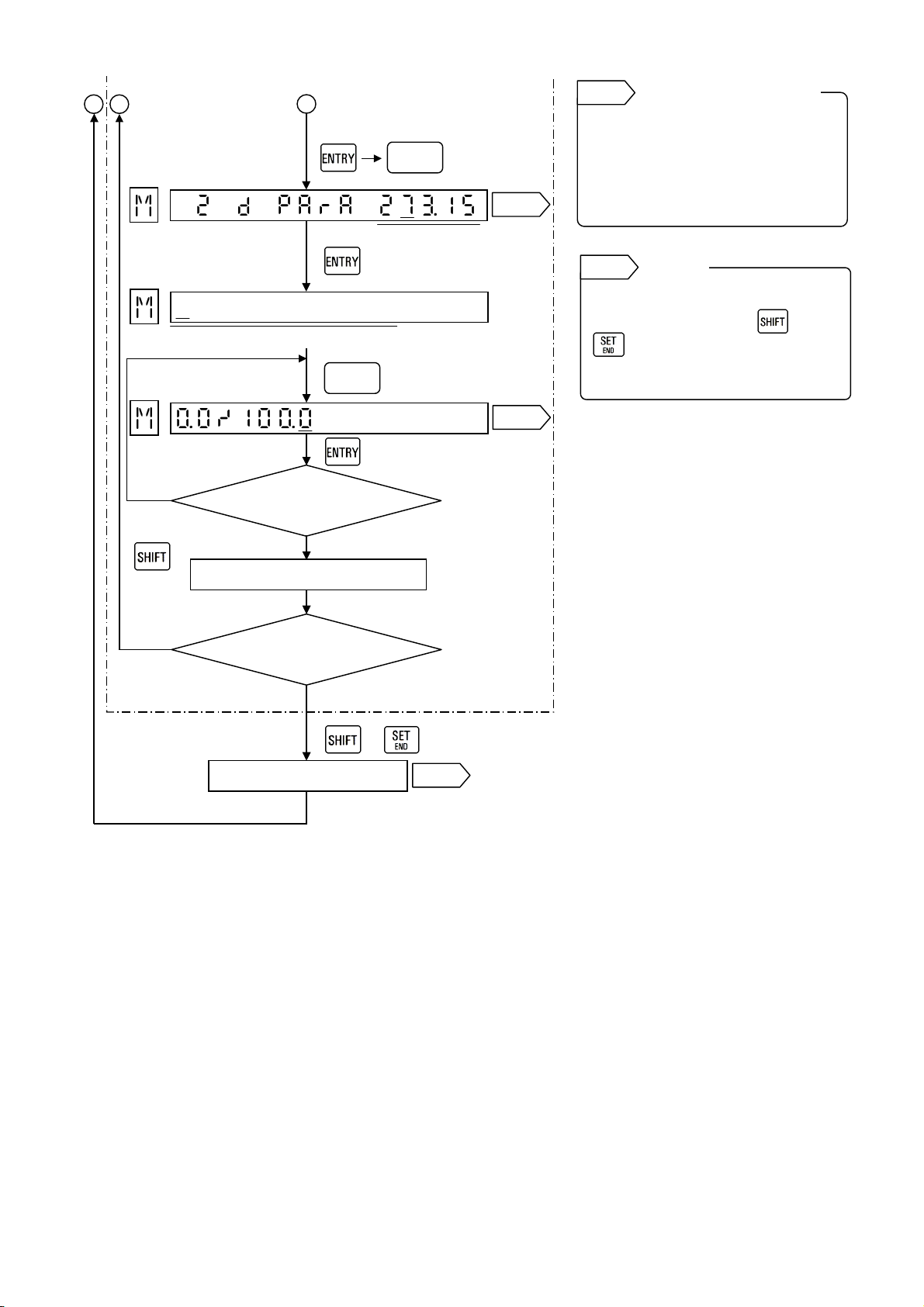
Page 25
C
A
f
B
[Programming Constant D]
[To printing range
programming]
Printing range (Min to Max)
[Programming
printing range]
Various
keys
Various
keys
Constant D
Ref. 3
Ref. 4
Ref. 4
Program the values within 5 digits
including a sign. The remaining
digits on the right side should be
kept blank. For the initial
programming, all digits are blank.
Ref. 5
Store “temporarily stored”
parameters by pressing and
simultaneously. If not, the
parameters programmed earlier
remain.
Programming range o
max. and min. values
Storing
YES
Any key
other than
YES
Error message appears?
NO
Temporarily stored
Programming other channels?
NO
+
Stored
Ref. 5
-23-
Page 26

[4] List printing
If the channels that math computation, totalizing computation or flow correction computation is programmed exist,
a list of these computations is printed after the scale printing (including engineering unit and tag).
[Example of list print]
CH MATH RECORD PARAMETERS
1 MUL 0.0~100.0 E:1 F:2
A: 2, B: 0, C: 0, D: 0
2 DIV 0.0~100.0 E:2 F:3
A:2, B:1.5
3 LOGE 0.00~100.00
4 LOG10 0.0~200.0
5 POWER 0.0~50.0
6 ROOT 0.0~100.0
2 HUMID 0.0~100.0 E:1 F:2
3 H-PEAK 0~1000 E:3
A: 01:00, B: 08:00
4 L-PEAK -100.0~100.0 E:4
A: 00:30, B:12:00
5 AVE 0.00~100.00 E:5
A: 01:00, B: 06:30
6 ABS 0.00~100.00
1 INT 0.0~1000.0 E:1 F:M
A: 00:30, B: 08:00
← Arithmetic computation 1
← Arithmetic computation 2
← Natural logarithm computation
← Logarithm computation
← Exponential computation
← Square root computation
← Temperature/humidity computation
← Maximum value computation
← Minimum value computation
← Average value computation
←Absolute value computation
← Totalizing computation
2 COMM 0.0~1000.0
1 FLOW1 0.0~100.0 E:2 F03
A: 273.15, B: 0, C: 1, D: 273.15
[Remark 1]
The above example is for AL3000.
For AH3000, Arithmetic computation 1, Arithmetic computation 2, Maximum value computation, Minimum
value computation, Average value computation and Totalizing computation are printed in a single line.
[Remark 2]
Parameters E and F
E is for x channel and F is for y channel.
For the totalizing computation, E is for a measuring channel and F is for a time unit.
[Remark3]
The printing format for FLoW2 to FLoW7 is same as FLoW1.
For FLoW3, the constant D is not printed because it does not exsist.
← Data communications input
←Flow correction computation1
-24-
Page 27

(By Sprung formula)
0.0 0.2 0.4 0.6 0.8 1.0 1.2 1.4 1.6 1.8 2.0 2.2 2.4 2.6 2.8 3.0 3.5 4.0 4.5 5.0 5.5 6.0 6.5 7 8 9 10 11 12 13 14
∆θ
40 100 99 98 96 95 94 93 92 91 89 88 87 86 85 84 83 81 78 76 73 71 69 67 65 61 57 54 51 48 45 43
38 100 99 97 96 95 94 93 91 90 89 88 87 86 85 84 83 80 78 75 73 71 68 66 64 60 56 53 50 47 44 42
36 100 99 97 96 95 94 92 91 90 89 88 87 85 84 83 82 79 77 74 72 70 68 65 63 59 56 52 49 46 43 41
34 100 99 97 96 95 93 92 91 90 88 87 86 85 84 83 82 79 76 74 71 69 67 64 62 58 55 51 48 44 42 39
32 100 99 97 96 95 93 92 91 89 88 87 86 84 83 82 81 78 76 73 70 68 66 63 61 57 53 50 46 43 41 38
30 100 99 97 96 94 93 92 90 89 88 86 85 84 83 82 80 77 75 72 69 67 65 62 60 56 52 48 45 42 39 36
28 100 99 97 96 94 93 91 90 89 87 86 85 83 82 81 80 77 74 71 68 66 63 61 59 55 51 47 43 40 37 35
26 100 98 97 95 94 92 91 90 88 87 85 84 83 81 80 79 76 73 70 67 65 62 60 57 53 49 45 42 39 36 33
24 100 98 97 95 94 92 91 89 88 86 85 83 82 81 79 78 75 72 69 66 63 61 58 56 51 47 43 40 37 34 31
22 100 98 97 95 93 92 90 89 87 86 84 83 81 80 78 77 74 71 68 65 62 59 57 54 50 45 41 38 35 31 29
20 100 98 96 95 93 91 90 88 86 85 83 82 80 79 77 76 73 69 66 63 60 58 55 52 48 43 39 35 32 29 26
18 100 98 96 94 93 91 89 87 86 84 83 81 79 78 76 75 71 68 65 62 59 56 53 50 45 41 37 33 30 27 24
16 100 98 96 94 92 90 89 87 85 83 82 80 78 77 75 74 70 66 63 60 57 54 51 48 43 38 34 30 27 24 21
[Appendix] Conversion table for temperature/humidity computation
θω
14 100 98 96 94 92 90 88 86 84 82 81 79 77 75 74 72 68 64 61 57 54 51 48 45 40 35 31 27 24 20 17
8 100 97 95 92 90 88 85 83 81 79 76 74 72 70 68 66 62 57 53 49 46 42 39 35 29 24 19 15 11
6 100 97 94 92 89 87 84 82 79 77 75 72 70 68 66 64 59 54 50 46 42 38 34 31 25 19 15 10
4 100 97 94 91 88 86 83 80 78 75 73 70 68 66 63 61 56 51 46 42 37 33 30 26 20 14
2 100 97 93 91 87 84 81 78 76 73 70 68 65 63 60 58 52 47 42 37 33 28 24 21 14
12 100 98 96 93 91 89 87 85 83 81 79 77 76 74 72 70 66 62 59 55 52 48 45 42 37 32 28 24 20 17 14
10 100 98 95 93 91 88 86 84 82 80 78 76 74 72 70 69 64 60 56 52 49 45 42 39 33 28 24 20 16 13 10
0 100 96 93 89 86 83 80 76 73 70 67 65 62 59 57 54 48 42 37 31 27 22 18 14
-2 100 96 92 88 85 81 78 74 71 68 64 61 58 55 52 50 43 37 31 25 20 15 11
-4 100 95 91 87 83 79 75 71 68 64 61 57 54 51 48 45 37 30 24 18 13
-6 100 95 90 86 81 77 72 68 64 60 56 53 49 45 42 39 30 23 16 10
-8 100 95 89 84 79 74 69 64 60 56 51 47 43 39 35 32 23 14
-10 100 94 88 82 76 71 65 60 55 50 45 40 36 32 27 23 13
∆θ: Temperature difference between dry bulb and wet bulb θω: Temperature of wet bulb (ºC)
-25-
Page 28

32-8, KUMANO-CHO, ITABASHI-KU, TOKYO 173-8632
Telepho ne : 81-3-3956-2171
Facsimile : 81-3-3956-0915
The fourth edition Dec. 2002
Printed in Japan ( )
 Loading...