

Page 1
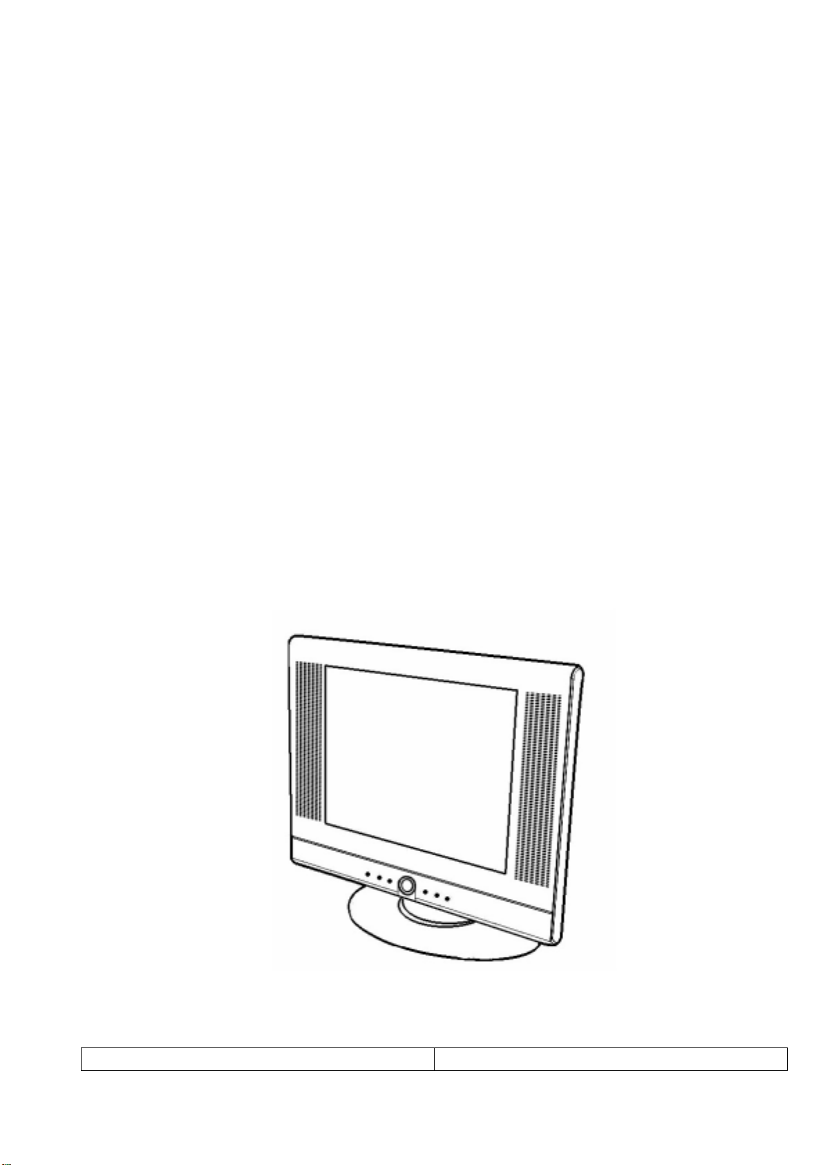
COLOR TFT-LCD TV
SERVICE MANUAL
MODEL : LT-15AMF
CAUTION !!
BEFORE SERVICING THE TFT-LCD TV,
READ THE SAFETY PRECAUTIONS IN THIS MANUAL.
LT-15AMF SERVICE MANUAL
PAGE:1
Page 2
SAFETY PRECAUTIONS
!! Important Safety Notice !!
Many electrical and mechanical parts in this chassis have special safety-related
characteristics.
These parts are identified by in the Schematic Diagram and Replacement Parts List.
It is essential that these special safety parts should be replaced with the same components
as recommended in this manual to prevent Shock, Fire, or other Hazards.
Do not modify the original design without permission of manufacturer.
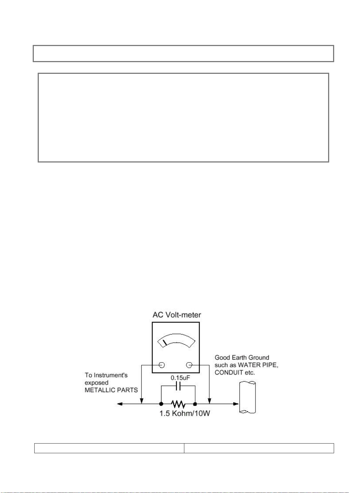
Leakage Current Hot Check (See below Figure)
Plug the AC cord directly into the AC outlet.
Do not use a line Isolation Transformer during this check.
Connect 1.5K/10watt resistor in parallel with a 0.15uF capacitor between a known good earth
ground (Water Pipe, Conduit, etc.) and the exposed metallic parts.
Measure the AC voltage across the resistor using AC voltmeter with 1000 ohms/volt or more
sensitivity.
Reverse plug of the AC cord into the AC outlet and repeat AC voltage measurements for each
exposed metallic part. Any voltage measured must not exceed 0.75 volt RMS, which is,
corresponds to 0.5mA.
In case any measurement is out of the limits specified, there is possibility of shock hazard and
the set must be checked and repaired before it is returned to the customer.
Leakage Current Hot Check circuit
LT-15AMF SERVICE MANUAL
PAGE:2
Page 3

SERVICING PRECAUTIONS
CAUTION!!
Before servicing receivers covered by this service manual, read and follow the SAFETY
PRECAUTIONS on page 3 of this publication.
General Servicing Precautions
1.Always unplug the receiver AC power cord from AC power source before;
ⓐRemoving or reinstalling any component, circuit board module or any other receiver assembly.
ⓑDisconnecting or reconnecting any receiver electrical plug or other electrical connection.
ⓒConnecting a test substitute in parallel with an electrolytic capacitor in the receiver.
CAUTION!! A wrong part substitution or incorrect polarity installation of electrolytic capacitors
may result in an explosion harzard.
2.Do not spray chemicals on or near this receiver or any of its assemblies.
3.Do not defect any plug/socket voltage interlocks with which receivers covered by this service
manual might be equipped.
4.Always connect the test receiver ground lead to the receiver chassis ground before
connecting the test receiver positive lead. Always remove the test receiver ground lead last.
5.Do not connect the test fixture ground strap to power supply heatsink in this receiver
Electrostatically Sensitive(ES) Devices
Some semiconductor(solid state) devices can be damaged easily by static electricity. Such
components commonly are called Electrostatically Sensitive(ES) Device.Examples
Circuit Board Foil Repair
Excessive heat applied to the copper foil of any printed circuit board will weaken the adhesive
that bonds the foil to the circuit board causing the foil th separate from or “lift-off” the board.
The following guidelines and procedures should be flollowed whenever this condition is
encountered.
At IC Connections
To repair a defective copper pattern at IC connections use the following procedure to install a
jumper wire on the copper pattern side of the circuit board.(Use this technique only on IC
connections.)
1.Carefully remove the damaged copper pattern with a sharp knife.(Remove only as much
copper as absolutely necessary.)
2.Carefully scratch away the solder resist and acrylic coating(if used) from the end of the
remaining coopper pattern.
3.Bend a small “U” in one end of a small guage jumper wire and carefully crimp it around the IC
pin.
4.Route the jumper wire along the path of the out-away copper pattern and let it overlap the
previously scraped end of the good copper pattern. Solder the overlapped area and clip off any
excess jumper wire.
LT-15AMF SERVICE MANUAL
PAGE:3
Page 4

CONTENTS
Safety precautions ----------------------------------------------------------- 2
Servicing precautions ------------------------------------------------------- 3
Contents ------------------------------------------------------------------------- 4
Specifications ----------------------------------------------------------------- 5
Location of control ---------------------------------------------------------- 8
Disassembly procedure ---------------------------------------------------- 11
Mechanical exploded view with part list ----------------------------- 20
Circuit descriptions --------------------------------------------------------- 21
Trouble shooting ------------------------------------------------------------- 35
Adjustment instruction with SVC mode ------------------------------ 38
Inspection instruction ------------------------------------------------------ 39
PCB Layout --------------------------------------------------------------------- 40
Part appearance -------------------------------------------------------------- 45
Packing instruction ---------------------------------------------------------- 47
Replacement Parts List ---------------------------------------------------- 48
Block diagram ---------------------------------------------------------------- 54
Connection diagram -------------------------------------------------------- 55
Schemetic diagram --------------------------------------------------------- 56
LT-15AMF SERVICE MANUAL
PAGE:4
Page 5

SPECIFICATIONS
Note: Specifications and others are subject to change without notice for improvement.
1.Scope.
This document is the specification of 15” TFT-LCD Color TV.
2.Power
1) Power requirement
DC 12V / 3A
2)AC / DC Adapter.
Input Frequency : 50/60㎐ ±3㎐
Input Voltage : AC 100V ~ AC 230V (±10%)
Output Voltage : DC 12V
3)Power cord
Use UL listed and CSA certified detachable power cord type ;SVT, 3-conductors, 18AWG
For AC 120V area. Use VDE listed detachable power cord type ;HO5VV-F, 3-conductors,
18AWG for AC 220~240V area.
3.Tuning system
FVS 100
4.Sound output
1W+1Wrms Stereo (Max)
5.Antenna input impedance
VHF / UHF at 75ohm
6.OSD Type (On Screen Display)
Windows type (Center)
7.External in/output
DC Power in, PC/DTV in, PC Audio in, COMPONENT, Head Phone out,
S-Video in, A/V in, ANT in.
Audio In : 0.4Vrms, over 10KΩ
Video In : 1Vp-p, over 75Ω
PC/DTV In: 0.7Vp, over 75Ω
8.Function
CATV/Hyper band
Auto Program
Manual Program
Auto Sleep
Quick view
PSM(Picture Status memory)
SSM(Sound Status memory)
LT-15AMF SERVICE MANUAL
PAGE:5
Page 6
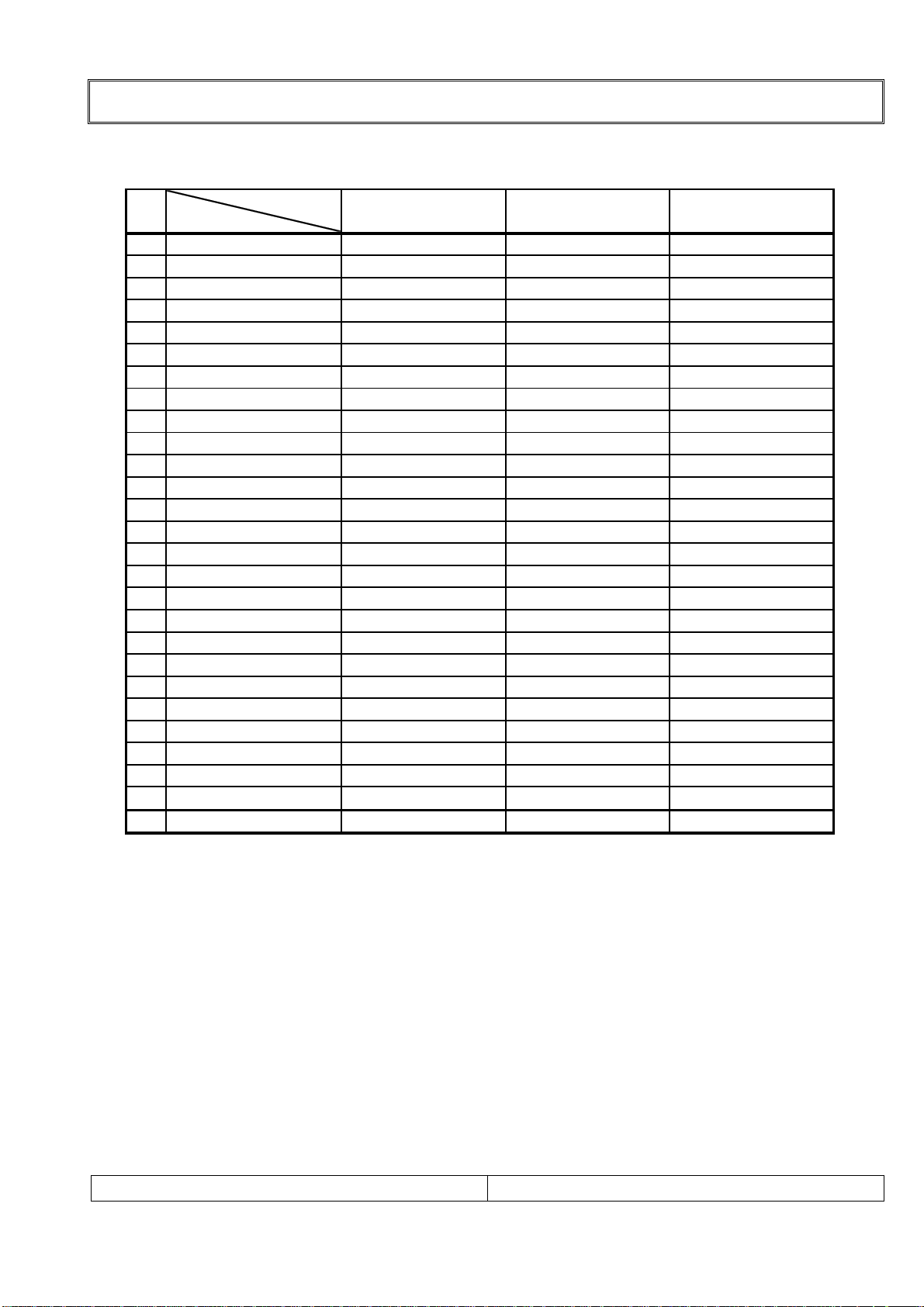
9.Receiving RF TV system
NO
Model System
1 PAL-B
2 PAL-G
3 PAL-I, I /I
4 PAL-D
5 PAL-K
6 SECAM-B
7 SECAM-G
8 SECAM-D
9 SECAM-K
10 SECAM-K1
11 SECAM-I (6.0)
12 NTSC-3.58 / 4.5
13 NTSC-3.58 / 5.5
14 NTSC-3.58 / 6.0
15 NTSC-3.58 / 6.5
16 NTSC-3.58 / 4.5(5.0)
17 NTSC-4.43 / 5.5
18 NTSC-4.43 / 6.0
19 NTSC-4.43 / 6.5
20 PAL 5.5 / 60Hz
21 PAL 6.0 / 60Hz
22 PAL 6.5 / 60Hz
23 SECAM 5.5 / 60Hz
24 SECAM 6.0 / 60Hz
25 SECAM 6.5 / 60Hz
26 SECAM L / L'
TOTAL SYSTEM 8
SPECIFICATIONS
LT-15AMF / /
X//
X//
X//
X//
X//
X//
X//
X//
X//
X//
X//
O//
O//
O//
O//
O//
O//
O//
O//
X//
X//
X//
X//
X//
X//
X//
//
LT-15AMF SERVICE MANUAL
PAGE:6
Page 7
SPECIFICATIONS
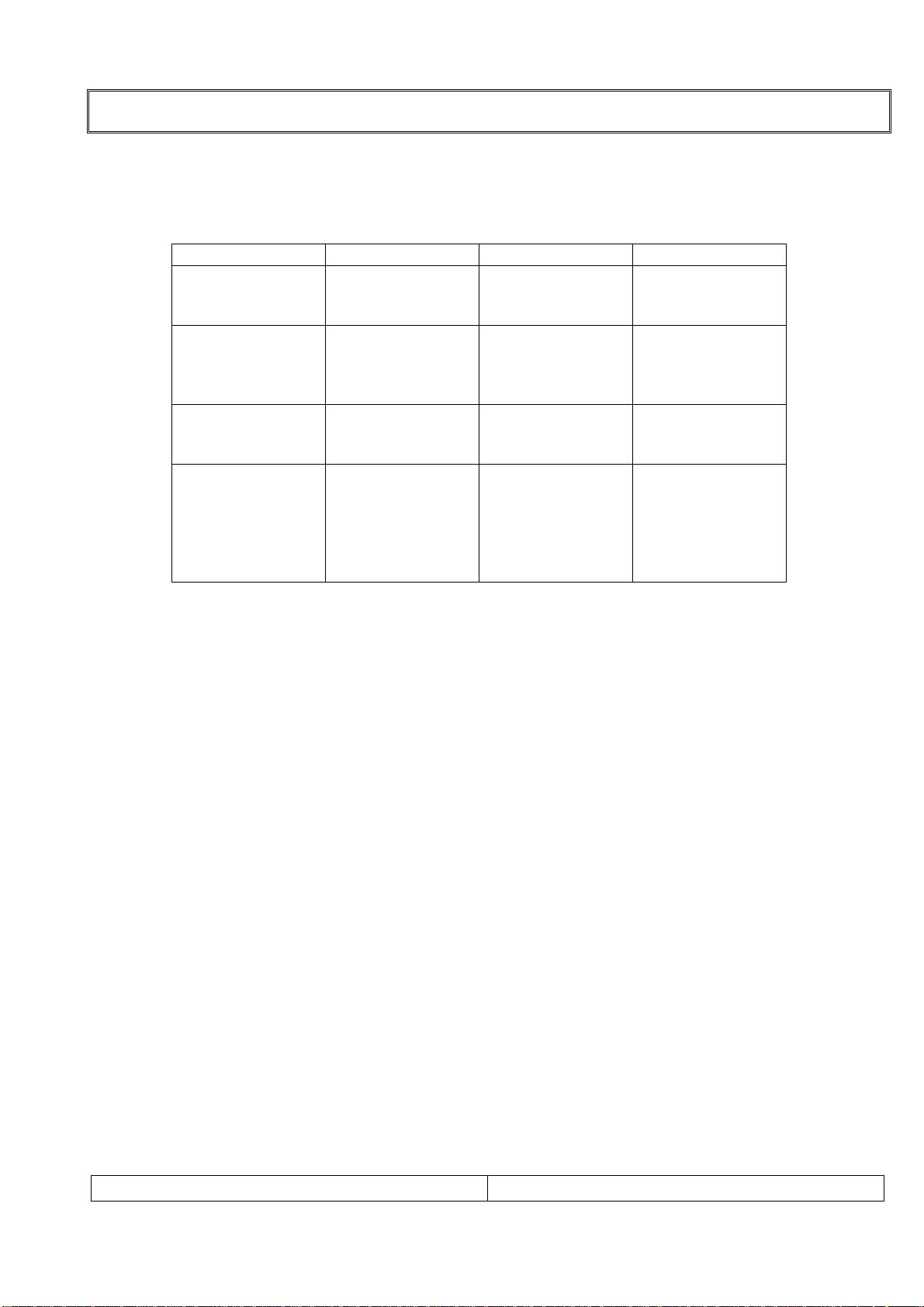
10. PC Mode Scan Frequency & Timing
1)Scan Freq : H: 31 ~ 56 kHz / V : 56 ~ 85㎐
2)Preset Timing Chart
Mode Resolution H-Freq(Khz) V-Freq(Khz)
VGA
SVGA
XGA
DTV (PC)
640x480
640x480
720x400
800x600
800x600
800x600
800x600
1024x768
1024x768
1024x768
720x480p
720x576p
1280x720p
1280x720p
1920x1080i
1920x1080i
37.9KHz
37.5KHz
31.5KHz
35.1KHz
37.9KHz
48.1KHz
46.9KHz
48.4Khz
56.5Khz
60.0Khz
31.5Khz
31.2Khz
45.0Khz
37.5Khz
33.7Khz
28.1Khz
72Hz
75Hz
70Hz
56Hz
60Hz
72Hz
75Hz
60Hz
70Hz
75Hz
60Hz
50Hz
60Hz
50Hz
60Hz
50Hz
Note!! :
ⓐ If the set is cold, there may be a small “flicker” when the set is switched on. This is
Normal, there is nothing wrong with the set.
ⓑ if possible, use the VESA 1024x768 PC video mode to obtain the best image quality for
your LCD TV. If used under the other resolutions, some scaled or processed pictures may
appear on the screen.
ⓒ some dot defects may appear on the screen, like Red, Green or Blue spot. However, this
will have no impact or effect on the monitor performance.
11. TFT – LCD Panel Character
1) Feature
Size :15" Diagonal (38Cm)
LCD Type :Color Active Matrix TFT
Pixel Pitch :0.297 mm(H) x 0.297 mm(V)
Pixel Format :1024x768 Pixels, RGB Stripe
Active Video Area :304.1mm(H) x 228.1mm(V)
Surface treatment :Haze 25, Anti-Glare & Hard coating(3H)
Response Time(Typ) :25mS(Typ)
Viewing Angle<CR≥10> : Hor [Left/Right] Æ 70Deg (Typ) / 70Deg (Typ),
Ver [High(Top)/Low(Bottom)] Æ 60Deg (Typ) / 65Deg (Typ)
Luminance(Typ) : 450 cd/㎡(Typ)
Contrast Ratio(Typ) : 350(Typ)
Display Color : 16,2M Color
Back Light : 4 CCFL
LT-15AMF SERVICE MANUAL
PAGE:7
Page 8
LOCATION OF CONTROL
A
All the function can be controlled with the remote controller.
Some functions can also adjusted with the buttons on the controls on the TV front panel.
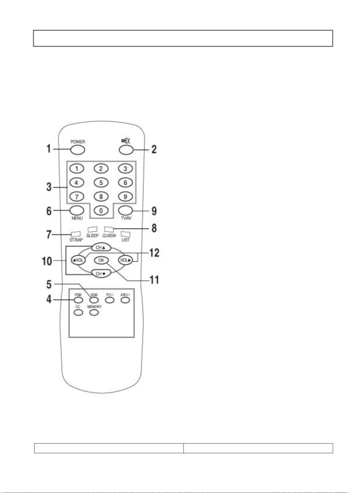
12-1. Remote controller
Note !! : Before you use the remote controller, please install the batteries.
1.POWER:
Turns the TV on from standby or off to
standby mode.
2.MUTE:
Turns the sound on and off
3.NUMBER buttons:
Select channel numbers.
4.PSM (Picture Status Memory):
Recalls your preferred picture setting.
5.SSM (Sound Status Memory):
Recalls your preferred sound setting.
6.MENU:
Displays a main menu.
7. ST / SAP:
Selects the MTS-Stereo, Mono and
SAP
8.Q.VIEW:
Returns to the previously viewed
Programme.
9.TV / AV: Selects TV, COMPONENT,
VIDEO, S-VIDEO, RADIO(Only when
the set is Radio On.) or PC mode.
/ Clears the menu from the screen.
10.CH ▲▼ ( Channel Up/Down):
Selects next channel or a menu item.
11.OK:
ccepts your selection or displays the
current mode.
12.VOL ◀▶ ( Volume Up/Down):
Adjusts the sound level or a menu
Setting.
LT-15AMF SERVICE MANUAL
PAGE:8
Page 9
LOCATION OF CONTROL
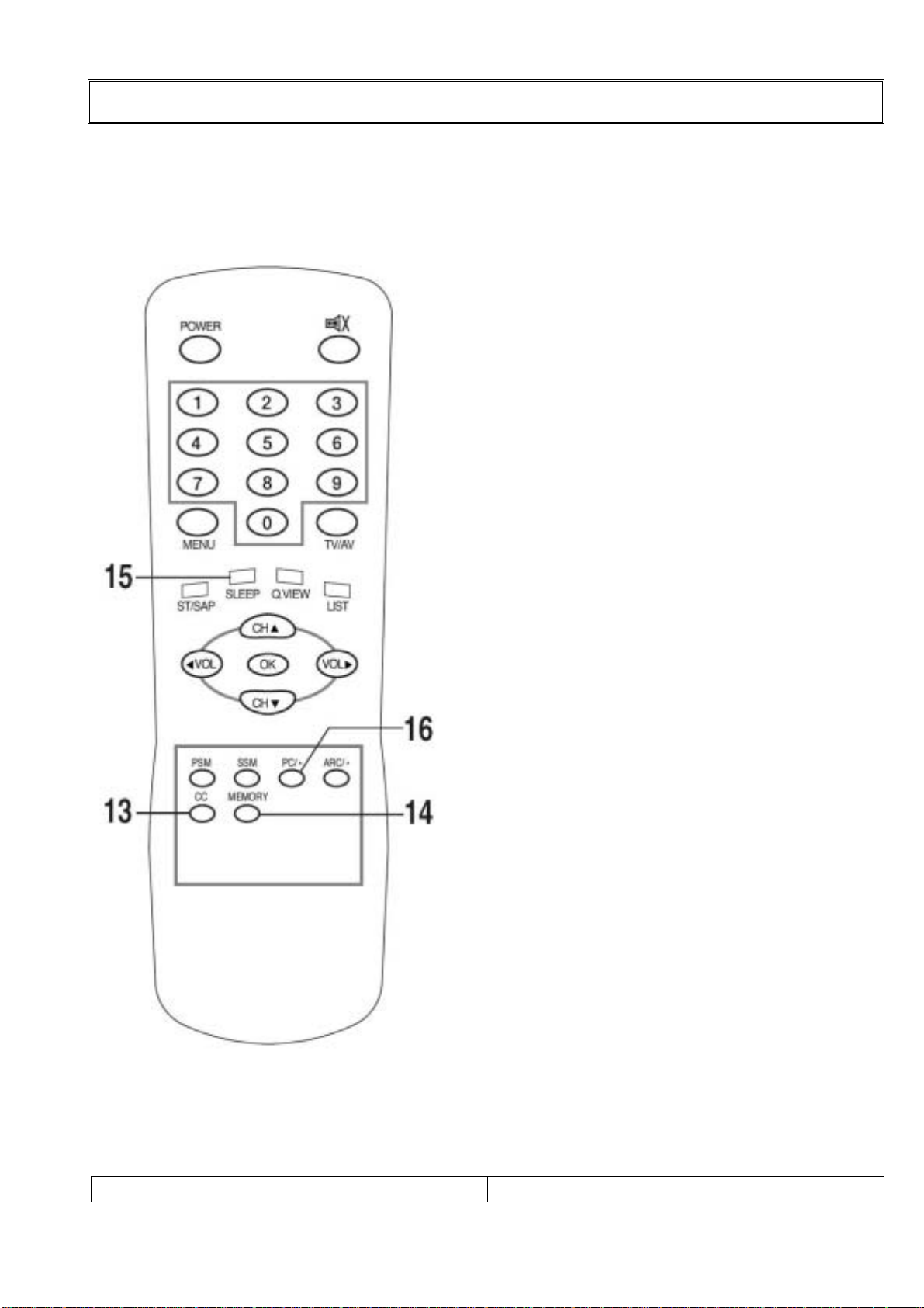
12-2. Remote controller
Note !! : Before you use the remote controller, please install the batteries.
13.CC
Sets the caption function.
14.MEMORY
Stores or removes the current
channel.
15.SLEEP
Sets the sleep timer.
16.PC/*
Selects PC mode directly.
LT-15AMF SERVICE MANUAL
PAGE:9
Page 10
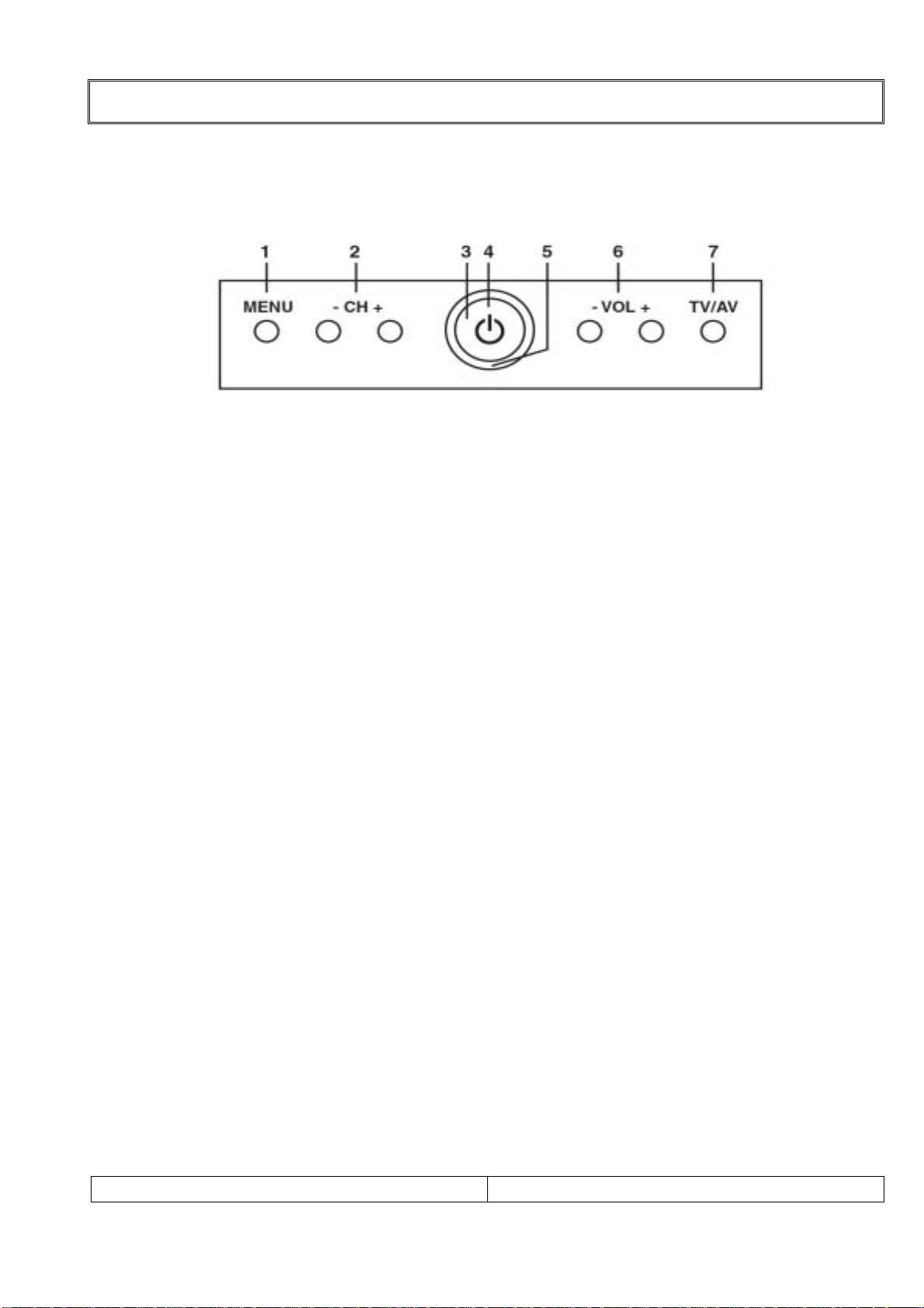
13. Controller of Panel
< FRONT VIEW>
1). MENU:
Display a menu.
2). + CH - ( Channel Up/Down):
Selects a channel or a menu item.
3). POWER INDICATOR:
Illuminates in red when the TV is in power standby mode.
Illuminates green when the TV is switched power on mode.
Illuminates blinked when the when the power save mode.(only PC mode.)
4). ON/OFF. Switches TV set on or off.
5). REMOTE CONTROL SENSOR.
Accepts the IR signal of remote controller.
6). + VOL - ( Volume Up / Down)
Adjusts the volume. / Adjusts menu settings.
7). TV/AV:
Selects TV, COMPONENT, VIDEO,
S-VIDEO, RADIO(Only when the set is Radio On.) or PC mode.
/ Clears the menu from the screen.
LOCATION OF CONTROL
LT-15AMF SERVICE MANUAL
PAGE:
10
Page 11
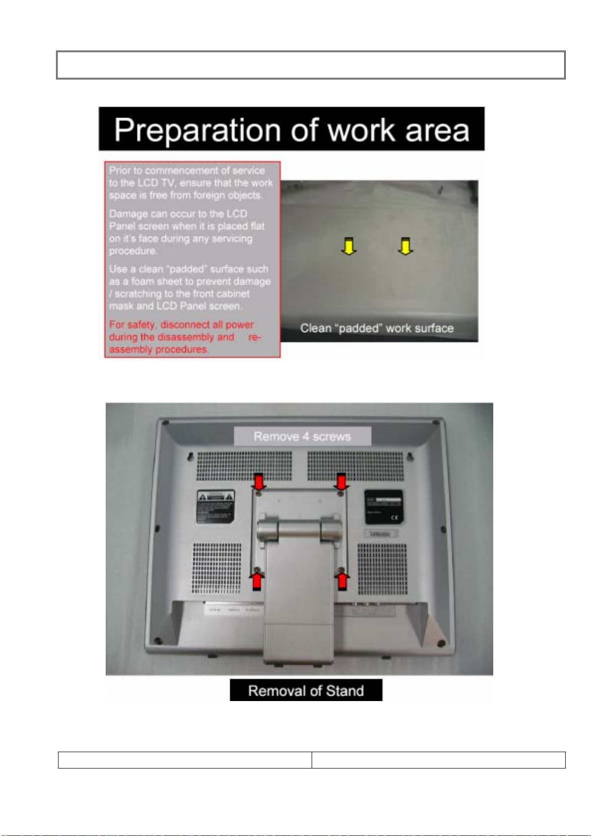
DISASSEMBLY PROCEDURE
14. Deassembly procedure
1).Removal of Stand
LT-15AMF SERVICE MANUAL
PAGE:
11
Page 12
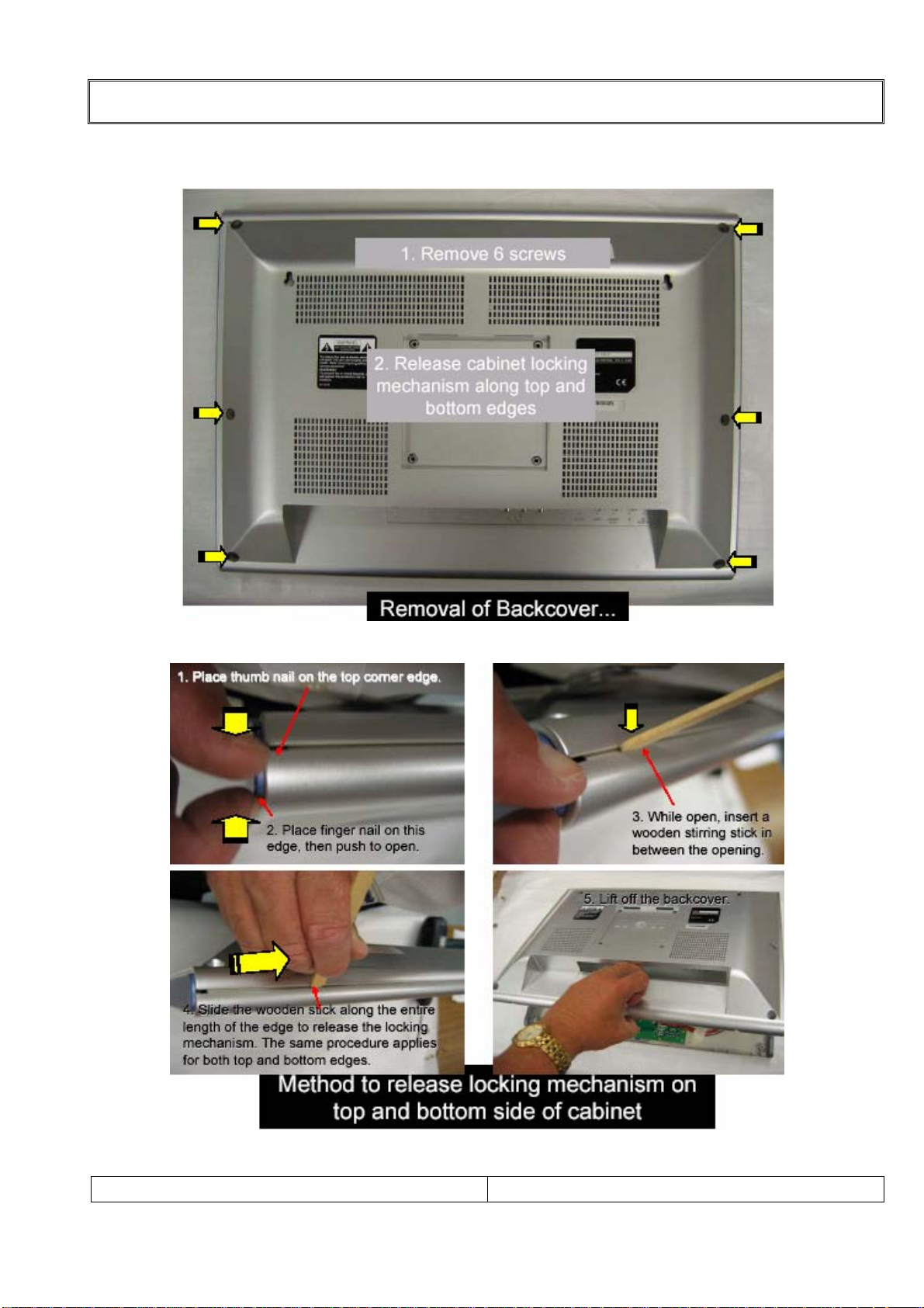
2).Removal Backcover
DISASSEMBLY PROCEDURE
LT-15AMF SERVICE MANUAL
PAGE:
12
Page 13
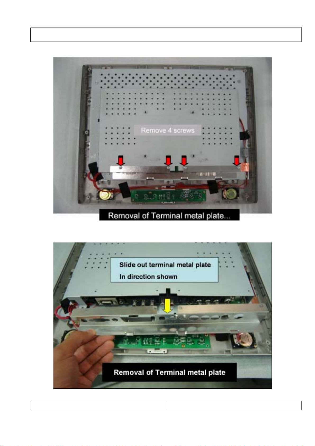
DISASSEMBLY PROCEDURE
3-1).Removal of Terminal metal plate
3-2).Removal of Terminal metal plate
LT-15AMF SERVICE MANUAL
PAGE:
13
Page 14
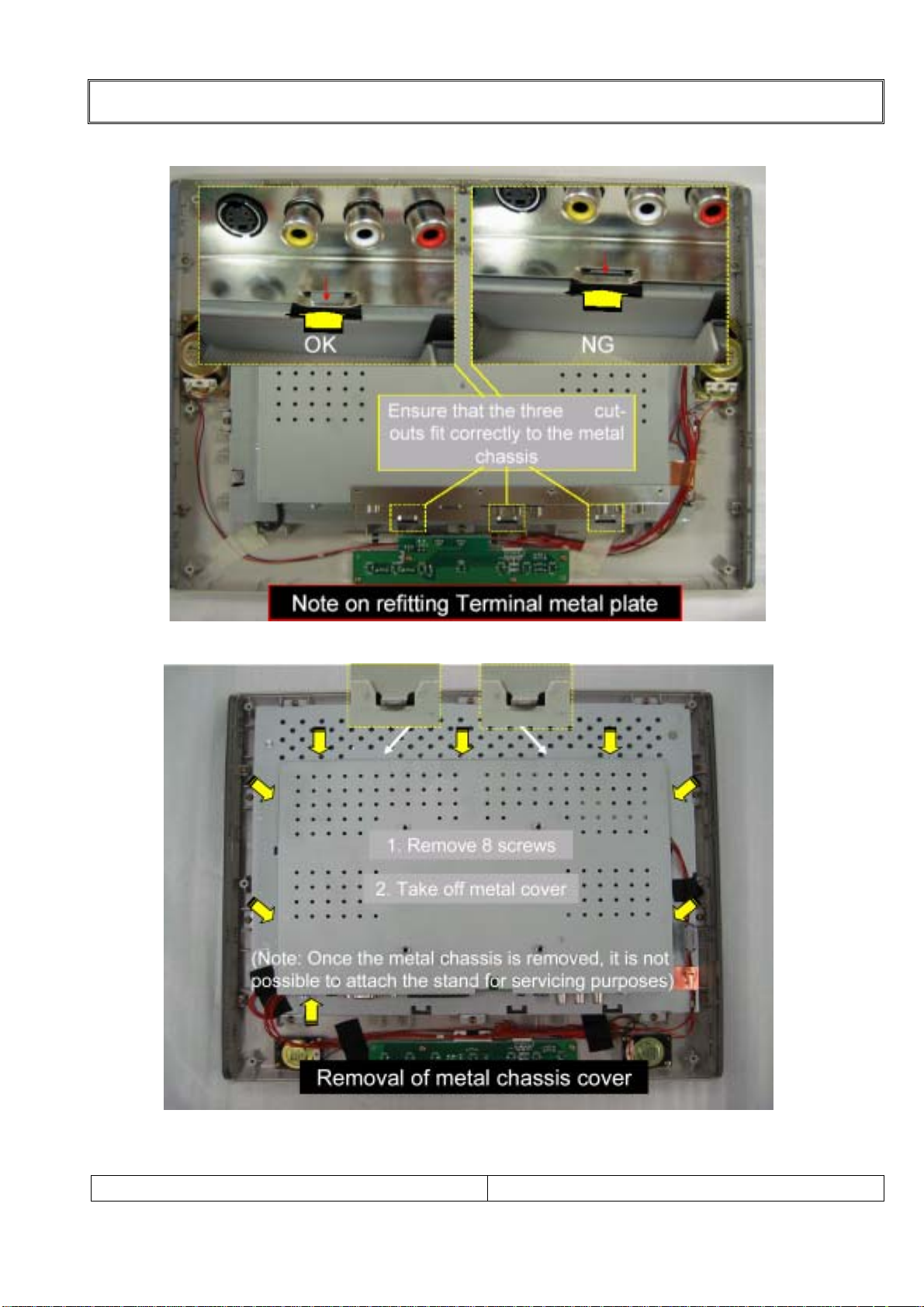
DISASSEMBLY PROCEDURE
4).Note on refitting terminal metal plate
5) Removal of metal chassis cover
LT-15AMF SERVICE MANUAL
PAGE:
14
Page 15
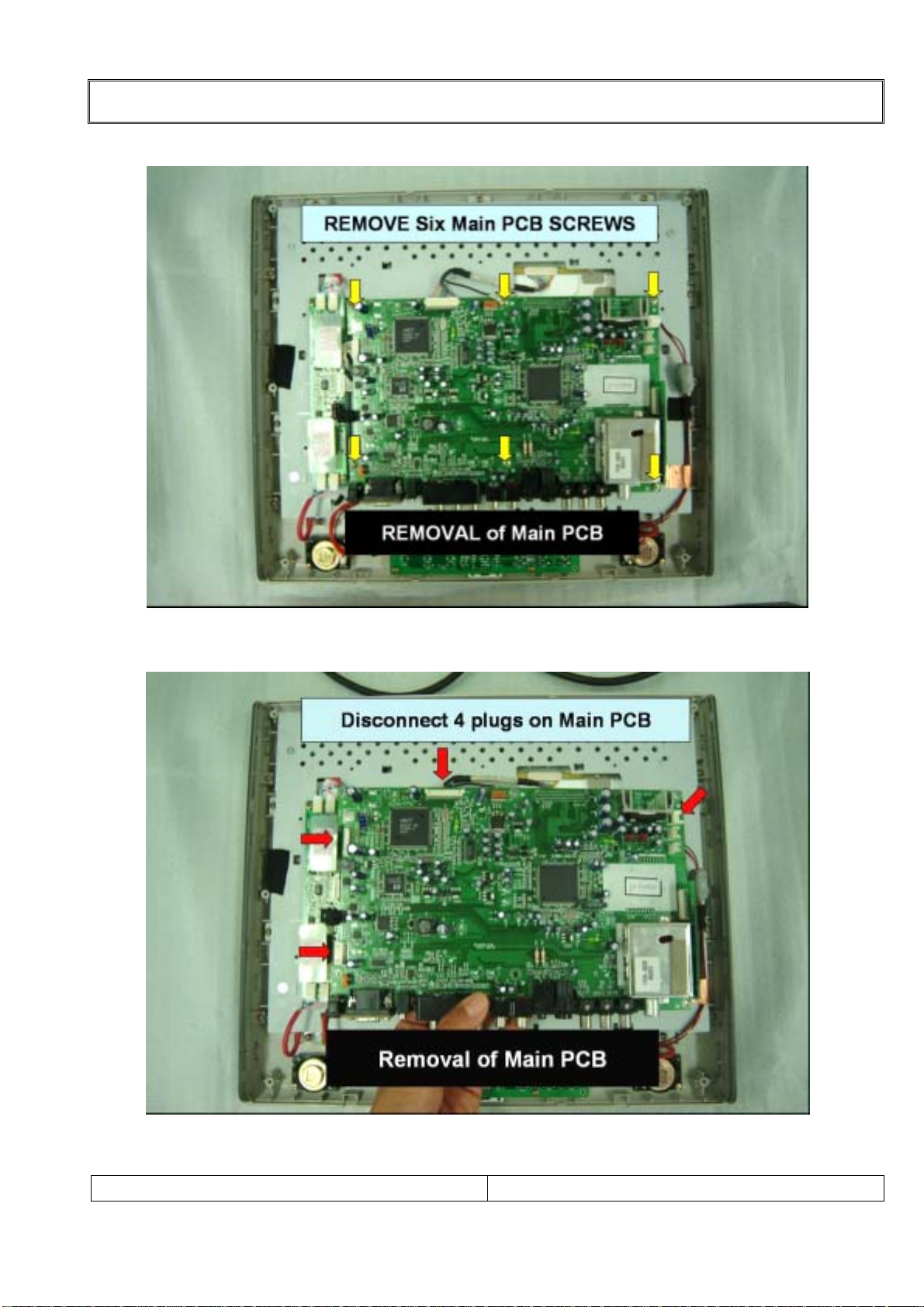
DISASSEMBLY PROCEDURE
6-1).Removal of Main PCB
6-2).Removal of Main PCB
LT-15AMF SERVICE MANUAL
PAGE:
15
Page 16
DISASSEMBLY PROCEDURE
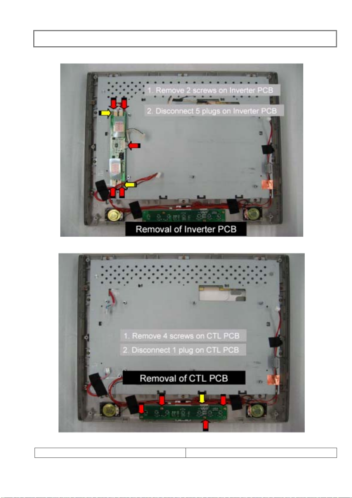
7).Removal of Inverter PCB
8)Removal of Control PCB
LT-15AMF SERVICE MANUAL
PAGE:
16
Page 17
DISASSEMBLY PROCEDURE
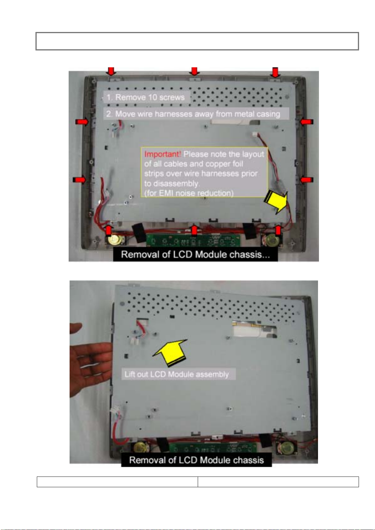
9-1).Removal of LCD Module chassis
9-2).Removal of LCD Module chassis
LT-15AMF SERVICE MANUAL
PAGE:
17
Page 18

DISASSEMBLY PROCEDURE
9-3).Removal of LCD Module chassis
9-4).Removal of LCD Module chassis
LT-15AMF SERVICE MANUAL
PAGE:
18
Page 19

DISASSEMBLY PROCEDURE
9-5).Removal of LCD Module chassis
LT-15AMF SERVICE MANUAL
PAGE:
19
Page 20

15.Explode View
NO PART NO DESCRI PTI ON MAT ERIAL COLO R Q 'TY
1 408-001A FI LTER LED PC BLUE 1
2 404-002A BLOCK KNOB ABS SILVER 1
3 AYCO LT15A01A CONT ROL PCB - - 1
4 401-011D COVER FRONT ABS SILVER 1
5 405-002A SI DE MOLD ABS DARK GRAY 2
6 P ANM150X 3000 PANEL - - 1
7 407-001P SHIELD F RONT EGI - 1
8 622-002D D/C,A/C INVERTER - - 1
9 AYMALT11B03C MAIN PCB ASS'Y - - 1
10 407-003A SHI ELD JACK S PTH - 1
11 407-002A SHI ELD REAR EGI - 1
12 401-002C COVER BACK ABS DARK GRAY 1
13 403- 002A HING E ASS 'Y - - 1
14 402- 002A HI NGE CO VER ABS SILV ER 1
15 402- 002B ST AND F RONT ABS S ILVE R 1
16 401-0010 STAND B RKT EGI - 1
17 402-002C STAND REAR ABS SILVER 1
18 402- 002E DECO BOT TOM AB S SI LVER 1
19 402-002D STAND BOTTOM ABS DARK GRAY 1
20 401-0011 BO TT OM BRK T EGI - -
21 410-001L SCREW T APPI NG TT B 3*10 SZN 12
22 410-001M SCREW T APPING BTB 3*6 SZN 12
23 410- 001A SCREW TAPPI NG PPT B 2.6*7 SZN 4
24 410- 001S SCREW TAPPI NG PP WS 3*8 SZ N 4
25 410-001K SCREW TAPPI NG TTB 3*8 SZN 16
26 410-001N SCREW MACHINE FTB 3*6 SZN 10
27 410-001P SCREW MACHINE FTB 3*4 S NI 12
MECHANICAL EXPLODED VIEW
26
8
25
32
4
LT15A EXPLODED DRAWING
14
13
30
28
12
27
9
27
26
7
30
17
30
30
16
15
18
30
19
30
30
11
20
10
3
6
2
1
21
5
22
LT-15AMF SERVICE MANUAL
PAG E:
20
Page 21

CIRCUIT DESCRIPTIONS
General Description for 15” color TFT LCD TV.
The TFT LCD TV described in the followings is based on a Multi TV system, digital
control display, 15” diagonal. The TFT LCD TV is intended to be a finished product,
basically a display device mounted inside an enclosure which will provide the safety
requirements. With the exception of LCD Panel, the display device shall be composed
entirely of solid state components.
These components shall have a history of reliable service in identity applications
and shall be applied in the circuits.
1.SCALER SECTION.
2.VCT 49xy SECTION.
16.SCALER SECTION.
Device : MVRL
Features : Advanced Image Scaling
Automatic Image Optimization
Digital Video processing
Non-linear scaling
On-screen display
8-bit display outputs
1) Description
Designed for both LVDS and Smart Panel with RSDS applications, MVRL is a highly
integrated solution that combines a high performance ADC with an advanced image
processing controller and timing control circuitry. Using advanced image scaling
algorithms, MVRL has intelligently adaptive sub-algorithms that will automatically optimize
the display quality for different images the text is sharper and the graphics is smoother.
The built-in analog interface includes a 110Mhz 8bit 3-channel ADC, VGA, and PLL,
allowing seamless support to resolutions from VGA to SXGA. MVRL includes timing
control circuit for handling gate and source driver ICs for SVGA/SXGA TET-LCD panel
directly.
LT-15AMF SERVICE MANUAL
PAGE:
21
Page 22

2) Block Diagram.
CIRCUIT DESCRIPTIONS
LT-15AMF SERVICE MANUAL
PAGE:
22
Page 23

3)Pin configuration.
CIRCUIT DESCRIPTIONS
LT-15AMF SERVICE MANUAL
PAGE:
23
Page 24

4-1)Pin Functions.
CIRCUIT DESCRIPTIONS
LT-15AMF SERVICE MANUAL
PAGE:
24
Page 25

4-2)Pin Functions.
CIRCUIT DESCRIPTIONS
LT-15AMF SERVICE MANUAL
PAGE:
25
Page 26

4-3)Pin Functions.
CIRCUIT DESCRIPTIONS
LT-15AMF SERVICE MANUAL
PAGE:
26
Page 27

4-4)Pin Functions.
CIRCUIT DESCRIPTIONS
LT-15AMF SERVICE MANUAL
PAGE:
27
Page 28

CIRCUIT DESCRIPTIONS
17.MCU SECTION.
Device : VCT 49xy
Features : Built-in teletext decoder.
8051 compatible.
Internal ROM type.
1) Description
The VCT 49xyI, VCT 48xyI is an IC family of high-qualitysingle-chip TV processors. Modular
design and deep-submicron technology allow the economic integration of features in all
classes of single-scan TVsets.
The VCT 49xyI, VCT 48xyI family is based on functional blocks contained and approved in
existing products like DRX 396xA, MSP 34x5G, VSP 94x7B, DDP 3315C, and SDA 55xx.
2) Blockl Diagram
LT-15AMF SERVICE MANUAL
PAGE:
28
Page 29

3)Pin configuration.
CIRCUIT DESCRIPTIONS
LT-15AMF SERVICE MANUAL
PAGE:
29
Page 30

4-1) Pin(Port) Functions
CIRCUIT DESCRIPTIONS
LT-15AMF SERVICE MANUAL
PAGE:
30
Page 31

4-2) Pin(Port) Functions
CIRCUIT DESCRIPTIONS
LT-15AMF SERVICE MANUAL
PAGE:
31
Page 32

4-3) Pin(Port) Functions
CIRCUIT DESCRIPTIONS
LT-15AMF SERVICE MANUAL
PAGE:
32
Page 33

4-4) Pin(Port) Functions
CIRCUIT DESCRIPTIONS
LT-15AMF SERVICE MANUAL
PAGE:
33
Page 34

4-5) Pin(Port) Functions
CIRCUIT DESCRIPTIONS
LT-15AMF SERVICE MANUAL
PAGE:
34
Page 35

18-1.Troble Shooting
TROUBLE SHOOTING
LT-15AMF SERVICE MANUAL
PAGE:
35
Page 36

18-2.Troble Shooting
TROUBLE SHOOTING
LT-15AMF SERVICE MANUAL
PAGE:
36
Page 37

18-3.Troble Shooting
TROUBLE SHOOTING
LT-15AMF SERVICE MANUAL
PAGE:
37
Page 38

ADJUSTMENT INSTRUCTION WITH SVC MODE
19.SVC mode data Adjustment
NOTE!! When the EEPROM has been replaced, the SVC data should be restored as the
function of individual system and specification.
[ Enter and exit SVC mode ]
Note: into the SVC mode, Initialize with default data.
1) Press 5 Seconds MENU buttons on both TV set and Remote Controller at the same
time to get into SVC mode.
2) Press the PR ▲▼ button several times to find SVC Data.
3) Input the corresponding SVC data referring to Table below with the VOL ◀▶, key.
4) Press TV/AV button to exit SVC mode
19-1. Factory outgoing setting & Initialize with default data (into the SVC mode)]
Main menu Change value Sub menu Change value
(Panel) 15
(Model) (M)
(TV White Balance) SYSTEM M/N
Option 1
Audio Options AV1 YUV2
(DRX) (Sub-menu) Text WEST_EU
(NVM Edit) (Sub-menu) Top YES
(Reset TV-set) (Sub-menu) VPS/PDC YES
Option 1
Sub-menu
China/Australia No
Data Service Text
ATS Delay Time 60
Audio Options
Sub-menu
Scart Volume 118
Mute if no carrier Yes
High Deviation No
M42
BG/I/DK 21
NICAM 26
FM Radio 10
Surround 0
DUAL No
MONO No
STEREO Yes
GAME No
Warning: Do not change the “( )” item…
LT-15AMF SERVICE MANUAL
PAGE:
38
Page 39

INSPECTION INSTRUCTION
20. Supplied Accessories
Note: Make Sure the following accessories are provided with Product.
LT-15AMF SERVICE MANUAL
PAGE:
39
Page 40

21-1.Main PCB
PCB LAYOUT
LT-15AMF SERVICE MANUAL
PAG E:
40
Page 41

21-2. Main PCB
PCB LAYOUT
LT-15AMF SERVICE MANUAL
PAG E:
41
Page 42

21-3. Main PCB
PCB LAYOUT
LT-15AMF SERVICE MANUAL
PAG E:
42
Page 43

21-4. Main PCB
PCB LAYOUT
LT-15AMF SERVICE MANUAL
PAG E:
43
Page 44

21-5. Control PCB
PCB LAYOUT
21-6. Tuner PCB
LT-15AMF SERVICE MANUAL
PAG E:
44
Page 45

22-1.Part appearance
P ART APPEARANCE
C3875S
C3198
A1504S
2N7000
C102S
RegulatorforTuningVoltage
LC33VorLD33V(LD1117)
EEPROM24C16W,24C02W
LT-15AMF SERVICE MANUAL
AP1501
DualFETSI4925
PAGE:
45
Page 46

22-2. Parts Appearance
P ART APPEARANCE
VoltageDetector
KIA7027AF
Schottky Rectifier B340
VoltageDetector
KIA7042AF
Voltage Reg
KIA78L05F
TTL LOGIC IC 74F08
Voltage Reg
KIA78L09F
LT-15AMF SERVICE MANUAL
PAGE:
46
Page 47

23.Packing instruction
PACKING INSTRUCTION
NO PART NO DESCRIPTION MATERIAL COLOR Q'TY
1 - LCD TV - - 1
2 321-002C BAG PACKING PE - 1
3 310-019A PA CKING (L) EPS - 1
4 310-019B PA CKING (R) EPS - 1
3
1
2
5 300-018E BOX GIFT PAPER - 1
6 - ACCESSORY ASS'Y - 7 610-002B TAPE - -
4
1SE T
530mm
5
6
7
LT-15AMF SERVICE MANUAL
PAGE:
47
Page 48

REPLACEMENT PART LIST
24-1.Parts List (Assemble process)
Level P/N DESCRIPTION FUNCTION Qty
1 300-003F 151/201 COMMON BOX BOX, ACCESSORY 1
1 300-017A 15ADE/17DE, NO BRAND BOX, CARTON 1
1 310-003A 15/17 A/D/E COMMON PACKING, LEFT 1
1 310-004A 15/17 A/D/E COMMON PACKING, RIGHT 1
1 320-001A ACCESSORY PACKING BAG, VINYL 1
1 321-002A 151 A/E SET PACKING BAG, PACKING 1
1 322-001A 15/17, HANDLE, WHITE HANDLE, UP 1
1 322-001B 15/17,HANDLE, WHITE HANDLE, DOWN 1
1 401-003B 151 A/E,VCTI/SILVER COVER, BACK 1
1 401-011N CMO/SS,15A,CH,SIL/GR COVER, FRONT 1
1 404-002A 15/17/20, L/KEY, SIL BLOCK KNOB 1
1 405-002A 15", GRAY SIDE MOLD 2
1 407-001T 151,VCTI SS F/S SHIELD, FRONT 1
1 407-002K 15 A/D/E,VCTI SS R/S SHIELD, REAR 1
1 407-005D 15.1",VCTI, YUV SHIELD, JACK 1
1 408-001A 15/17/20",A/D FILTER FILTER, LED 1
1 410-001K TTB 3*8 SCREW 10
1 410-001L TTB 3*10 SCREW 4
1 410-001M BTB 3*6 SCREW 12
1 410-001N FTB 3*6 SCREW 8
1 410-001P FTB 3*4 SCREW 12
1 410-001Q BTB 4*12 SCREW 6
1 410-002Z PB 3*10 SCREW 4
1 410-003Q PP 4*8 SCREW 4
1 490-011C 71TS-FK 20-2-34-13-S FORM, SHIELD 1
1 491-001A W40mm,L20mm, COPPER TAPE, CONDUCTIVE 1
1 492-001A CLIP, ZCAT1325-0530 FERRITE CORE 1
1 499-001C W:20mm TAPE, OPP 130
1 499-002A W:70mm TAPE, OPP 1200
1 499-004A W:20mm, L:30m TAPE, ACETATE 100
1 500-027M
1 501-001W LATIN,SPANISH,COMMON LABEL, WARNING 1
1 501-0030 SILVER/BLACK LABEL,SERIAL 2
1 501-017L SANYO,15/20,45mm STICKER, LOGO 1
1 501-102A LT-15AMF,ARDWSAF0 LABEL, ID 1
1 509-021A
1 510-011J NO BRAND,CH,ARC REMOCON 1
1 520-001A 1.5V, AAA SIZE BATTERY 2
1 610-002A 3W, 8 OHM SPEAKER 2
1 620-002D 12V 3.5A 1.8M SiTech AC/DC ADAPTER(WEEE) 1
1 621-001C 125V,3P,KKP-30(USA) POWER CORD 1
1 622-002D 151, FIF1742-39A INVERTER, DC-AC 1
1 626-002C IVORY,1.8M,15P,SHORT CABLE, PC RGB 1
1 627-001A 1.8M, BK CABLE, PC-SOUND 1
1 AYCOLT15A01C A/D,15/17/20,VCTI CONTROL PCB ASSY 1
1 AYMALT41B01C 151 VCTI,YUV,NTSC MAIN PCB ASSY 1
1 AYSTLT15A01A 15/17.1, A/D-MODEL STAND ASSY 1
1 CON04P200A0V 151 SPK,4P,R650L280 LEAD ASSY 1
1 CON07P200ABR 15 CTRL 7P 550MM R/B LEAD ASSY 1
1 CON12P125ABC 15SS 17IPS,AUO INVER LEAD ASSY 1
1 CON20P125ABE PANEL,20-PIN,120MM LEAD ASSY 1
1 PANM150XHL06 SS, 15",LTM150XH-L06 PANEL, LCD COLOR 1
15AMF,NOBRAND,중남미
SANYO,15/20 공용
OWNERS MANUAL 1
LABEL, BRAND 2
LT-15AMF SERVICE MANUAL
PAGE:
48
Page 49

REPLACEMENT PART LIST
N
N
24-2.Parts List (Main PCB)
Main PCB Ass'y
P/N
AYMALT41B01C
GRLT41AM001A GR, COM MON MANUAL
LEVEL
1 WAFYH10200SD WAFER, PIN 10-PIN, P2.0mm STRAIGHT P114 1
1 WAFYH03200SD SMW200-03 Pin wafer, 3-PIN P602 1
1 WAFYH02200SD SMW200-02 Pin wafer, 2-PIN P601 1
1 WAFYH04200AD Pin wafer, 4-PIN P603 1
1 WAFML07200AD 53015-0710 Wafer, 7-PIN P111 1
1 WAFLG04250SD GIL-G-4P-S3T2 Pin wafer, 4-PIN P110 1
1 1JADM231000D DS231-115 Jack, DC-Power J801 1
1 0XTKI202500D Crystal, 20.25MHZ X100 1
1 0XTKI120000D Crystal, 12MHZ X10 1
1 0LRSM00100BD SMC103 Inductor, 1MH L802 1
1 0JAPK014A00D PMJ014A Jack, A/V+HP+SVHS J402 1
1 0JAKKST215BD ST-215 Jack, PC-AUDIO J403 1
1 0JADM15RF00D DAH-15RF-4B4 Jack, D-SUB J410 1
1 0ICKE78080AD KIA7808AP IC, KIA7808 IC800 1
1 AYHSLA4282IB GR, HEAT SINK MANUAL IC601 1
분류
1 1SFEPX6965MD X6965M SAW FILTER EPCOS EPCOS
1 0JAPK6063C0D PJ6063C Jack, YUV
1 0JAPK6035J2D PJ6035J2 Jack, YUV SOUND
PART NO PART NAME DESCRIPTI O N Circuit No. Q'ty
GRLT41AM001D GR, NTSC MANUAL
P/N VENDOR P/N Description Device N
Description
111-A42A-15KMF
unction
GRLT41AM001F GR, TUNER' MANUAL NTSC
분류
1 111-A45A 15/17 VCTI Tuner PCB
1 0TULGH017FBD TAEU-H017F Tuner
1 499-004A ACETATE TAPE
1 WAFYH10200AD BMH200-10R Pin wafer, 10-Pin
P/N VENDOR P/N Description Device N
LT-15AMF SERVICE MANUAL
PAGE:
49
unction
Page 50

REPLACEMENT PART LIST
24-3.Parts List (Main PCB)
GRLT41AA001A GR, COMMON AUTO
분류
2 1ICFC2N700TR 2N7000TA IC, 2N7000 Q120,Q121 2
2 1DZSSHZT33TA DIODE, ZENER AXIAL 33V, HZT33 ZD802 1
2 1DDSKEU1Z0TA EU1Z (MAKER: SANKEN) Diode, axial EU1Z D801 1
2 0RDSS121FJTA DR1/2WJ121 Resistor, RD 120 ohm R224,R225 2
2 0LBSS3580RTR BFD-3580R2F Bead, radial 1UH L807 1
2 0LASS220HKTA AL04 TB 220K Inductor, axial 22uH L150,L199,L410 3
2 0CQSS682KKTR Capacitor, MYLER C604,C605 2
2 0CESS4R7HMTR CESSL1H4R7M0511AD Capacitor, AL.E 4.7UF 50V C106,C807 2
2 0CESS471CMTR Capacitor, AL.E 470UF 16V C610,C612,C613,C813,C851 5
2 0CESS470CMTR CESSL1C470M0511AD Capacitor, AL.E 47UF 16V
2 0CESS3R3HMTR CESSL1H3R3M0511AD Capacitor, AL.E 3.3UF 50V C121 1
2 0CESS2R2HMTR CESSL1H2R2M0511AA Capacitor, AL.E 2.2UF 50V C177,C179,C222,C602,C606 5
2 0CESS221EMTR CESSL1E221M0611AD Capacitor, AL.E 220UF 25V C800 1
2 0CESS221CMTR CESSL1C221M0611AD Capacitor, AL.E 220UF 16V C151,C190,C827,C852 4
2 0CESS101EMTR CESSL1E101M0611AD Capacitor, AL.E 100UF 25V
2 0CESS100CMTR CESSL1C100M0511AD Capacitor, AL.E 10UF 16V
2 0CESS100HMTR CESSL1H100M0511AD Capacitor, AL.E 10UF 50V C853 1
P/N VE NDOR P/N Description Circuit No. Q'ty
C101,C104,C129,C130,C160,
C186,C330,C403,C405,C411,
C412,C413,C414,C419,C614,
C808,C809,C811,C812,C856
C601,C603,C607,C804,C816,
C850
C140,C141,C144,C150,C165,
C169,C170,C171,C172,C175,
C818,C820,C822,C824
20
6
14
GRLT41AA001C GR, YUV AUT O
분류
2 0CESS010HMTR 0CE105CK638 Capacitor, AL.E 1UF 50V C215,C216 2
분류
3 1ICSTLD33DTS LD1085D2M33R,D2PAK/A IC, REGULATOR IC808 1
3 0RHSS000DJTS RC1608J000CS Resistor, chip 0 ohm C805 1
3 0RHSS000EJTS RC2012J000CS Resistor, chip 0 OHM R821,R855 2
분류
3 111-A42A Main PCB VCTI Main PCB 1
3 WAFYH20125AS 12507WR-20 Wafer, 20-PIN ANGLE P01 1
3 WAFYH12125AS Wafer, 12-PIN, P 1.25mm ANGLE P803 1
3 1ICSTLD33TTS LD1117S33TR LD1117S33TR-3.3V IC301,IC811,IC830,IC833 4
3 1ICSTLD25TTS LD1117S25TR LD1117S25TR-2.5V IC810 1
3 1ICSTLD18TTS LD1117S18TR LD1117S18TR-1.8V IC831,IC832 2
3 1ICPH74F08TS IC, AND GATE QUAD 2INPUT AND GATE IC702 1
3 1ICST24C02W S SGS-THOMSON, 24C02W IC, 24C02 IC701 1
3 1ICSE24C16TS S-24C16AFJA-TB IC, 24C16 IC103 1
P/N VE NDOR P/N Description Circuit No. Q'ty
GRLT41BS001B GR, 15 inch Samsung Panel SMD
P/N VE NDOR P/N Description Circuit No. Q'ty
GRLT41AS001A GR, COMMON SMD
P/N VE NDOR P/N Description Circuit No. Q'ty
LT-15AMF SERVICE MANUAL
PAGE:
50
Page 51

REPLACEMENT PART LIST
24-4.Parts List (Main PCB)
3 1ICRO7657FBS BA7657F IC, BA7657F IC401 1
3 1ICRO6161FTS BA6161F DC/DC CONVERTER,30~45V IC803 1
3 1ICMRTMVRLBS MVRL IC, SCALER IC10 1
3 1ICMI49XYFC7 VCTI, 49XYF-C7 VCTI, 49XYF-C7 IC101 1
3 1ICIPAP5K5TS AP1501A-5.0V IC, Regulator AP 1501-5.0V/5.0A IC804 1
D700,D701,ZD191,ZD192,
ZD202,ZD203,ZD204,ZD209,
3 1DZSC5231BTS MMSZ5231BS Zener diode, chip 5.1V
3 1DHSTYW020TS DIODE, CHIP SMBYW02-200 D100,D802 2
3 0TRKE3875STS C3875 Transistor, chip C3875 Q102,Q800 2
3 0TRKE1504STS KTA1504S Y Transistor, chip A1504
3 0RHSS750DJTS RC1608J750CS Resistor, chip 75 ohm
3 0RHSS683DJTS RC1608J683CS Resistor, chip 68K R410,R614 2
3 0RHSS561DJTS RC1608J561CS Resistor, chip 560 ohm R604,R608 2
3 0RHSS513DJTS RC1608J513CS Resistor, chip 51K R220 1
3 0RHSS512DJTS RC1608J512CS Resistor, chip 5.1K
3 0RHSS474DJTS RC1608J474CS Resistor, chip 470K R202,R203,R232,R233,R404 5
3 0RHSS473DJTS RC1608J473CS Resistor, chip 47K R126,R158 2
3 0RHSS472DJTS RC1608J472CS Resistor, chip 4.7K
3 0RHSS331DJTS RC1608J331CS Resistor, chip 330 ohm R227 1
3 0RHSS3R3DJTS RC1608J3R3CS Resistor, chip 3.3 OHM R610,R611 2
3 0RHSS392DJTS RC1608J392CS Resistor, chip 3.9K R124,R125 2
3 0RHSS332DJTS RC1608J332CS Resistor, chip 3.3K
3 0RHSS272DJTS RC1608J272CS Resistor, chip 2.7K R112 1
3 0RHSS271DJTS RC1608J271CS Resistor,chip 270 R103,R104,R116 3
3 0RHSS223DJTS RC1608J223CS Resistor, chip 22K R156 1
3 0RHSS220DJTS RC1608J220CS Resistor, chip 22 ohm
3 0RHSS202DJTS RC1608J202CS Resistor, chip 2K R408 1
3 0RHSS152DJTS RC1608J152CS Resistor, chip 1.5K R70 1
3 0RHSS151DJTS RC1608J151CS Resistor, chip 150 ohm
3 0RHSS122DJTS RC1608J122CS Resistor, chip 1.2K R809 1
3 0RHSS105DJTS RC1608J105CS Resistor, chip 1M R26 1
3 0RHSS104DJTS RC1608J104CS Resistor, chip 100K R808 1
3 0RHSS103DJTS RC1608J103CS Resistor, chip 10K
3 0RHSS102DJTS RC1608J102CS Resistor, chip 1K
3 0RHSS101DJTS RC1608J101CS Resistor, chip 100 ohm
ZD210,ZD211,ZD212,ZD213,
ZD214,ZD215,ZD702,ZD703,
ZD704,ZD705,ZD706
Q100,Q101,Q103,Q104,Q105,
Q601
R28,R30,R32,R209,R228,
R229,R234,R714,R715,R716,
R718,R719,R720
R191,R200,R201,R217,R218,
R230,R231
R605,R606,R607,R612,R700,
R709,R710
R105,R119,R121,R122,R123,
R134,R136,R157,R172
R111,R207,R25,R701,R702,
R704,R705,R80,R800,R81,
R82
R100,R101,R102,R113,R114,
R115,R23,R24,R27,R29,
R31,R51,R613
R190,R20,R616,R706,R707,
R802
R117,R15,R18,R19,R609,
R615,R803
R120,R129,R132,R133,R135,
R137,R138,R139,R140,R141,
R142,R143,R145,R146,R147,
R148,R149,R150,R151,R153,
R159,R160,R179,R180,R400,
R401,R403,R405,R406,R409,
R411,R713,R717,R721,R722
19
6
13
7
7
9
11
13
6
7
35
LT-15AMF SERVICE MANUAL
PAGE:
51
Page 52

REPLACEMENT PART LIST
24-5.Parts List (Main PCB)
3 0RHSS100DJTS RC1608J100CS Resistor, chip 10 ohm R712 1
3 0RHSS000EJTS RC2012J000CS Resistor, chip 0 OHM
3 0RHSS000DJTS RC1608J000CS Resistor, chip 0 ohm
3 0LYSS600DJTS CIA31J600NES Bead, chip 60 ohm 3216 ar AL10,AL11,AL14,AL15 4
3 0LRSL10100BS SMD12128.5 Inductor, SMD, 33UH L850 1
3 0LHSS120EJTS 2012 CIL10Y120KNC Inductor, Chip 12UH L211 1
0LHSS100EKTS 2012 10UH Inductor, Chip 10UH
3
3 0LBSS601FJTS CIM31J601 Bead, chip 600 ohm 3216
3 0LBSS121EJTS Bead, chip 120 ohm 2012 C400,C407,C408 3
3 0LBSS101DJTS CIM21U101 Bead, chip 100 ohm 2012
3 0ICVI4925DTS IC, MOSFET CHIP DUAL P-CHANNEL 30V MOSFET IC820,IC821 2
3 0ICKE78L5FTS 78LO5 KIA78L05F IC838 1
3 0ICKE7027FTS KIA7027AF IC, KA7027 IC104 1
3 0DSSCB340ATS B340A DIODE, SCHOTTKY CHIP D850 1
3 0DHKEKDS226S KDS226, DIODE Diode, chip KDS226 D110 1
3 0DHKEKDS181S KDS181, DIODE Diode, chip KDS181 D601,D602 2
3 0CHSS560DJTS CL10C560JBNC Capacitor, chip 56PF C223 1
3 0CHSS472DKTS CL10B472KBNC Capacitor, chip 4700PF C26,C30,C36 3
3 0CHSS471DJTS CL10C471JBNC Capacitor, chip 470PF
3 0CHSS393DKTS CL10B393KANC Capacitor, chip 0.039UF C41 1
3 0CHSS334DZTS Capacitor, chip 0.33UF
3 0CHSS331DJTS CL10C331JBNC Capacitor, chip 330PF C153,C154 2
3 0CHSS330DJTS CL10C330JBNC Capacitor, chip 33PF C145,C146 2
3 0CHSS224DZTS CL10C224JBNC Capacitor, chip 0.22UF C189 1
3 0CHSS220DJTS CL10C220JBNC Capacitor, Chip, 22PF C23,C24 2
3 0CHSS152DKTS CL10B152KBNC Capacitor, chip 1500PF C176 1
3 0CHSS151DJTS CL10C151JBNC Capacitor, chip 150PF C40 1
3 0CHSS105DZTS CL10F105ZPNC Capacitor, chip 1UF C409 1
3 0CHSS104DZTS CL10F104ZANC Capacitor, chip 0.1UF
L161,L166,L172,L210,L800,
R801,R851,R852,R861,R880
C135,C224,R118,R127,R128,
R14,R171,R199,R402,R407
L164,L165,L181 3
L100,L101,L102,L160,L167,
L168,L171,L175,L180,L601,
L803,L804,L805,L806,L809
L200,L201,L207,L208,L209,
L212,L213,L700,L701,L702
C108,C109,C110,C122,C149,
C162,C200,C201,C205,C206,
C225,C226,C402
C116,C117,C118,C119,C131,
C132
C10,C100,C107,C11,C111,
C12,C120,C123,C124,C125,
C127,C128,C13,C133,C134,
C136,C137,C138,C14,C142,
C143,C15,C16,C166,C17,
C18,C180,C19,C191,C21,
C22,C25,C29,C33,C39,
C42,C608,C609,C611,C700,
C701,C801,C802,C803,C806,
C810,C815,C819,C821,C823,
C825
10
10
15
10
13
6
51
C185,C192,C193,C217,C218,
3 0CHSS103DKTS CL10B103KBNC Capacitor, chip 0.01UF
3 0CHSS102DKTS CL10B102KBNC Capacitor, chip 1000PF
3 0CHSS101DJTS CL10C101JBNC Capacitor, chip 100PF C155,C156 2
3 0CHSS100DJTS CL10C100DBNC Capacitor, chip 10PF C703 1
3 0CHSS080DCTS 8P Capacitor, chip 8PF C220 1
C27,C28,C31,C32,C34,
C35,C37,C38,C404,C406,
C410,C415,C416,C417,C418
C112,C113,C114,C115,C163,
C20
LT-15AMF SERVICE MANUAL
PAGE:
52
20
6
Page 53

REPLACEMENT PART LIST
C300,C301,C302,C303,C306,C
R301,R305,R306,R307,R309,R
24-6.Parts List (Main PCB)
GRLT41AS001C GR, YUV SMD
분류
3 0RHSS750DJTS RC1608J750CS Resistor, chip 75 ohm C211,C213 2
3 0RHSS474DJTS RC1608J474CS Resistor, chip 470K R223,R226 2
3 0RHSS393DJTS RC1608J393CS Resistor, chip 39K R219 1
3 0RHSS101DJTS RC1608J101CS Resistor, chip 100 ohm R144,R154,R155,R208 4
3 0RHSS000DJTS RC1608J000CS Resistor, chip 0 ohm R204,R221,R222 3
분류
3 0CHSS030DCTS CL10C030CBNC Capacitor, chip 3PF C326 1
3 0CHSS102DKTS CL10B102KBNC Capacitor, chip 1000PF C322 1
3 0CHSS104DZTS CL10F104ZANC Capacitor, chip 0.1UF
3 0CHSS473DKTS CL10B473KANC Capacitor, chip 0.047UF C311,C318,C320 3
3 0LBSS260DJTS CIB21P260NE Bead, chip 26 ohm 2012 L300 1
3 0LBSS601FJTS CIM31J601 Bead, chip 600 ohm 3216 L301,L302 2
3 0RHSS000DJTS RC1608J000CS Resistor, chip 0 ohm R302,R304,R308,R310 4
3 0RHSS103DJTS RC1608J103CS Resistor, chip 10K R300 1
3 0RHSS220DJTS RC1608J220CS Resistor, chip 22 ohm
3 1ICMS9883CBS MST9883C-110 IC, MST9883C IC300 1
P/N VE NDOR P/N Description Circuit No. Q'ty
GRLT41AS001G GR, DTV S MD
P/N VE NDOR P/N Description Circuit No. Q'ty
20
7
LT-15AMF SERVICE MANUAL
53
PAGE:
Page 54

25. Block Diagram
BLOCK DIAGRAM
LT-15AMF SERVICE MANUAL
PAGE:
54
Page 55

26. Connection diagram
CONNECTION DIAGRAM
PANEL
(2P+2P)
x2
I
N
V
E
R
T
E
R
PC
B
20P
2P2P
12P
MAIN PCB
RIGHT SPKLEFT SPK
2P
7P
A
D
A
P
T
E
R
3P
AC INPUT
CONTROL PCB
LT-15AMF SERVICE MANUAL
PAGE:
55
Page 56

 Loading...