

Page 1

SERVICE MANUAL
Page 2

*** CONTENTS ***
1.Safety Instructions
2. General Alignment
3. IC BLOCK DIAGRAM
4. TROUBLE SHOOTING
5. BLOCK DIAGRAM
6. CIRCUIT DIAGRAM
Page 3

* * * WARNING * * *
3
In order to prevent electric shock, do not remove cover.
No user-serviceable parts inside, Refer servicing to qualified service personal.
1. SAFETY INSTRUCTIONS
PRECAUTIONS DURING SERVICING
1. In addition to safety, other parts and assemblies are specified for conformance with such
regulations as those applying to spurious radiation. These must also be replaced only with
specified replacements.
Examples : RF converters, tuner units, antenna selection switches, RF cables, noise-blocking
capacitors, noise-blocking filters, etc.
2. Use specified internal Wiring. Note especially:
1) Wires covered with PVC tubing
2) Double insulated wires
3) High voltage leags
3. Use specified insulating materials for hazardous live parts. Note especially:
1) Insulation Tape
2) PVC tubing
3) Spacers (Insulation barriers)
4) Insulation sheets for transistors
5) Plastic screws for fixing micro switches
4. When replacing AC primary side components (transformers, power cords, noise blocking
capacitors etc), wrap ends of wires securely about the terminals before soldering.
5. Make sure that wires do not contact heat-generating parts (heat sinks, oxide metal film resistors,
fusible resistors, etc.)
6. Check if replaced wires do not contact sharply edged or pointed parts.
7. Make sure that foreign objects (screws, solder droplets, etc.) do not remain inside the set.
MAKE YOUR CONTRIBUTION T O PROTECT THE ENVIR ONMENT
Used batteries with the ISO symbol for recycling as well as small accumulators (rechargeable
batteries), mini-batteries (cells) and starter batteries should not be thrown into garbage can. Please
leave them at an appropriate depot.
WARNING
Page 4

Before servicing this TV receiver, read the X-RAY RADIATION PRECAUTION, SAFETY
4
INSTRUTION and PRODUCT SAFETY NOTICE.
X-RAY RADIATION PRECAUTION
1. Excessively high voltage can produce potentially hazardous X-RAY RADIATION. To avoid
such hazards, the high voltage must not exceed the specified limit. The normal value of the high
voltage of this TV receiver is
The hi
gh voltage must not exceed 29 kV under an circumstances : Each time when a receiver
require servicing, the high voltage should be checked. The reading of the high voltage is
recommended to be recorded as a part of the service record. It is important to use an accurate
and reliable high voltage meter.
2. The only source of X-RAY RADIATION in this TV receiver is the picture tube. For continued
X-RAY RADIATION protection, the replacement tube must be exactly the same type as
specified in the parts list.
3. Some parts in this TV receiver have special safety related characteristics for X-RAY
RADIATION protection. For continued safety, the parts replacement should be under taken only
after referring the PRODUCUT SAFETY NOTICE.
26 kV at ze
ro beam current (minimum brightness).
SAFETY INSTRUCTIONS
The service should not be attempted by anyone unfamiliar with the necessary instructions on this
TV receiver. The following are the necessary instructions to be observed before servicing.
1. An isolation transformer should be connected in the power line between the receiver and the AC
line when a service is performed on the primary of the converter tran sformer of the set.
2. Comply with all caution and safety related provided on the back of the cabinet, inside the
cabinet, on the chassis or picture tube.
3. To avoid a shock hazard, always discharge the picture tube’s anode to the chassis ground before
removing the anode cap.
4. Completely discharge the high potential voltage of the picture tube before handling. The picture
tube is a vacuum and if broken, the glass will explode.
5. When replacing a MAIN PCB in the cabinet, always be certain that all protective are installed
properly such as control knobs, adjustment covers or shields, barriers isolation resistor networks
etc.
6. When servicing is required, observe the original lead dressing. Extra precautio n should be given
to assure correct lead dressing in the high voltage area.
Page 5
7. Keep wires away from high voltage or high temperature components.
5
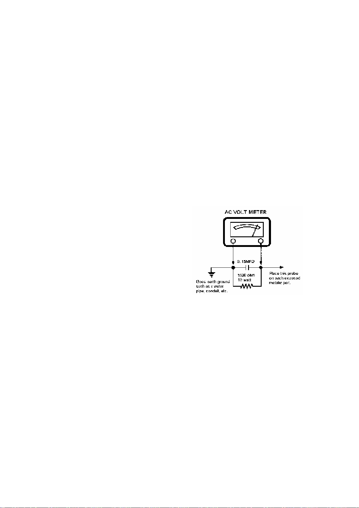
8. Before returning the set to the customer, always perform an AC leakage current check on the
exposed metallic parts of the cabinet, such as antennas, terminals, screw heads, metal overlays,
control shafts etc., to be sure the set is safe to operate without danger of electrical shock. Plug
the AC line cord directly to the AC outlet (do not use a line isolation transformer during this
check). Use an AC voltmeter having 5k ohms per volt sensitivity or more in the following
manner. Connect a 1.5k ohm 10 watt resistor paralleled by a 0.15uF AC type capacitor, between
a good earth ground (water pipe, conductor etc.) and the exposed metallic parts, one at a time.
Measure the AC voltage across the combination of 1.5k ohms resistor and 0.15uF capacitor.
Reverse the AC plug at the AC outlet and repeat AC voltage measurements for each exposed
metallic part. The measured Voltage must not exceed 0.3V RMS. This corresponds to 0.5mA AC.
Any value exceeding this limit constitutes a potential shock hazard and must be corrected
immediately.
The resistance measurement should be done
between accessible exposed metal parts and
power cord plug prongs with the power
switch “ON”. The resistance should be more
than 6M ohms.
PROODUCT SAFETY NOTICE
Many electrical and mechanical parts in this TV receiver have special safety-related
characteristics. These characteristics are often passed unnoticed by a visual inspection and th e
protection afforded by them cannot necessarily be obtained by using replacement components
rated for higher voltage, wattage, etc. Replacement part which have these special safety
characteristics are identified in this manual and its.
Supplements : Electrical components having such features are identified by shading on the
schematic diagram and the part list. Before replacing any of these components, read the parts
list in this manual carefully. The use of substitute replacement parts which do not have same
safety characteristics as specified in the parts list may create shock, fire or other hazards.
Page 6
2. GENERAL ALIGNMENT
6
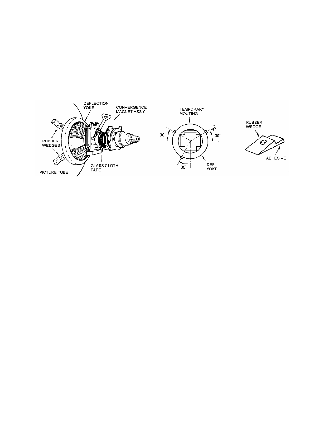
CPT MAGNET ADJUSTMENT
CONVERGENCE MAGNET ASSEMBLY POSITIONING
Convergence magnet assembly and rubber wedges need m echani cal posi t i oni n g follo wi n g fig ure 1.
FIG 1 Rubber Wedges Location
COLOR-PURITY-ADJUSTMENT
NOTE : Before attempting any purity adjustments, the receiver should be operated for at least 15
minutes.
1. Demagnetize the picture tube and cabinet using a degaussing coil.
2. Turn the CONTRAST and BRIGHTNESS controls to maximum.
3. Adjust RED and BLUE Bias controls to provide only a green rather.
4. Loosen the clamp screw holding the yoke, and slide the yoke backward to provide vertical green
belt(zone) in the picture screen.
5. Remote the Rubber Wedges.
6. Rotate and spread the tabs of the purity magnet(See figure 2) around the neck of the picture tube
until the green belt is in the center of the screen. At the same time, center the raster vertically.
7. Move, the yoke slowly forward until a uniform green screen is obtained. Tighten the clamp screw
of the yoke temporarily.
8. Check the purity of the red and blue raster by adjusting the BIAS controls.
9. Obtain a white raster, referring to "CTR GRAY SCAL ADJUSTMENT".
10. Proceed with convergence adjustment
Page 7
7
FIG 2
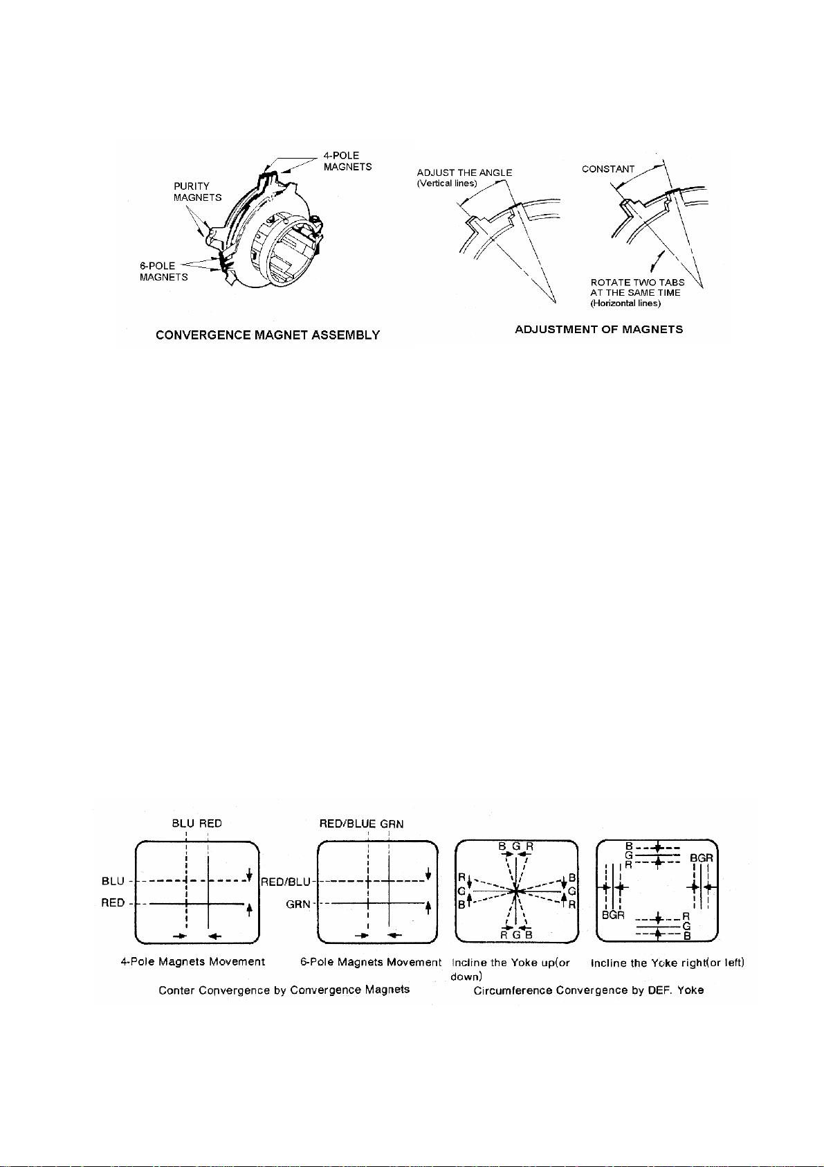
CONVERGENCE ADJUSTMENTS
NOTE : Before attempting any convergence adjustments, the receiver should be operate for at least
15 minutes.
CENTER CONVERGENCE ADJUSTMENT
1. Receiver crosshatch pattern with a color bar signal generator.
2. Adjust the BRIGHTNESS and CONTRAST Controls for well defined pattern.
3. Adjust two tabs of the 4-Pole Magnets to change the angle between them (See figure 3) and
superimpose red and blue vertical lines in the center area of the picture screen.
4. Turn both tabs at the same time keep in their angles constant to superimpose red and blue
horizontal lines at the center of the screen. (See figure 4.)
5. Adjust two tabs of 6-Pole Magnets to superimpose red/blue line with green one. Adjusting the
angle affects the vertical lines and rotating both magnets affects the horizontal lines
6. Repeat adjustment 3, 4, 5 Keeping in mind red, green and blue moment, because 4-Pole Magnets
and 6-Pole Magnets interact and make dot movement complex.
FIG 3 FIG 4
Page 8

8
CIRCUMFERENCE CONVERGENCE ADJUSTMENT
NOTE : This adjustment requires Rubber Wedge Kit.
1. Loosen the clamping screw of deflection yoke to allow the yoke to tilt.
2. Place a wedge as shown in figure (1) temporarily.
(Do not remove cover paper on adhesive part of the wedge.)
3. Tilt fron t of the deflection yoke up or down to obtain better convergence in circumference.(See
figure 4) Push the mounted wedge into the space between picture tube and the yoke to hold the
yoke temporarily.
4. Place other wedge into bottom space and remove the cover paper to stick.
5. Tilt front of the yoke right or left to obtain better convergence in circumference.(See figure 4).
6. Hold the yoke position and put another wedge in either upper space. Remove cover paper and
stick the wedges, recheck overall convergence.
7. Detach the temporarily mounted wedge and put it in another upper space. Stick it on picture tube
to fix the yoke.
8. After placing three wedges, recheck overall convergence. Tighten the screw firmly to hold the
yoke tightly in place.
9. Stick 3 adhesive tapes on wedges as shown in figure 1.
CHASSIS ADJUSTMENT MANUAL
How to enter the service the service mode using the user remote control
Push buttons of remote control in sequences as follows
‘DISPLAY’-‘MUTE’-‘SLEEP’-‘FUSSY’
1.HEAT RUN(AUTO POWER ON MODE) : F4
- It need in assembly line during heat run that protect to auto power off after no
signal 15 minutes and
auto power on for input power of sets on/off by line condition which
sometimes line power connection of palette with main power line would be
badly contacted by shaking during the sets through on assembly lines.
- Heat run function is operated by pressing the F4 key.
- To cancel this function press the F4 key one more or power on/off.
- It must be canceled before final output.
Page 9

1.HEAT RUN(AUTO POWER ON MODE) : F4
9
- It need in assembly line during heat run that protect to auto power off after no signal 15 minutes and auto power on for input
power of sets on/off by line condition which sometimes line power connection of palette with main power line would be badly
contacted by shaking during the sets through on assembly lines.
- Heat run function is operated by pressing the F4 key.
- To cancel this function press the F4 key one more or power on/off.
- It must be canceled before final output.
-
2. GEOMETRY ADJUSTMENT (F2)
If press “F2”key, The 2 adjustment modes are toggled that “GEOMETRY” and “PINCUSHION”mode.
2-1. V-SIZE
- Select the V-SIZE by pressing CH UP/DOWN key
- Adjust the V-SIZE by pressing VOL UP/DOWN key for approximately one-half inch over scan at top and bottom
of picture screen.
2-2. V-CENTER
-.For receive PAL-N (50Hz) RETMA pattern, press the “ CH “ key on the remote control
- Select the V-CENTER by pressing CH UP/DOWN key.
- Adjust V-CENTER so that the circle of Retma signal may be centered in the verical direction..
2-3.V-OFFSET
-.For receive NTSC-M or PAL-M (60Hz) RETMA pattern, press the “ CH “ key on the remote control
- Select the V-OFFSET by pressing CH UP/DOWN key.
- Adjust V-OFFSET so that the circle of Retma signal may be centered in the verical direction..
-.By this adjustment, we can compensate the difference of vertical center according to reception signal which is
50Hz or 60Hz.
2-4. H-CENTER
- Select the H-CENTER by pressing CH UP/DOWN key.
- Adjust the H-CENTER by pressing VOL UP/DOWN key to be coincident with screen center and mechanical center.
2-5. V-LIN.
-.Adjust vertical linearity by pressing VOL UP/DOWN key.
3.PIN CUSHION ADJUSTMENT(F2)
3-1. H.WIDTH
- For receive RETMA pattern, press the “ CH “ key on the remote control.
- Select the H-WIDTH by pressing CH UP/DOWN key.
- Adjust the H-WIDTH by pressing VOL UP/DOWN key so that the left and right side of picture may position an
interval of 4-BAR and 5 BAR.
3-2. PINCUSHION
9
Page 10

- For receive CROSS HATCH pattern,press the “CH”key on the remocon.
10
- Select the PINSHION by pressing CH UP/DOWN key.
-. When the vertical lines of the left and right side are distorted, adjust the PINSHION by pressing VOL UP/DOWN key.
so hat the vertical lines may be straight.
3-3. PIN. TILT
- For receive CROSS HATCH pattern,press the “CH”key on the remocon.
- Select the PIN.TILT by pressing CH UP/DOWN key.
-.When the screen shape is not rectangular but trapezoid, adjust the PIN.TILT by pressing VOL UP/DOWN key.
to correct the unbalanced shape.
3-4.PIN.TOP & PIN.BOT.
- For receive CROSS HATCH pattern,press the “CH”key on the remocon.
- Select the PIN.TOP or PIN.BOT by pressing CH UP/DOWN key.
-. When the vertical lines of theTOP or BOTTOM side are not straight but distorted, adjust PIN.TOP &PIN.BOT.
by pressing VOL UP/DOWN key to correct the unbalanced TOP or BOTTOM vertical lines.
.
3-5.PIN.COR.SW.
-.It is no need to adjust, set this data “1”
-.Check if the top and bottom side of the vertical lines are straight .
3-6.H.WIDTH COMP.
-.It is no need to adjust, set this data “6”
-.Check if the H.Width is the same according to the reception of low beam and High beam signal.
4.. SCREEN ADJUSTMENT(F3)
- Receive the video no signal.
- Select the SERVICE mode by pressing CH UP/DOWN key.
- Make the horizontal line by pressing VOL UP/DOWN key.
- Adjust the SCREEN , till horizontal line is just disappeared.
5. WH ITE BALANCE ADJUSTMENT.(F3)
- Receive a black and white pattern or white balance adjusting pattern.
- Before attempting white balance adjustment, the receiver should be operate for at least 15minites.
- Check the all of position to the reference value (nominal center)
- The reference color of the measurement equipment set to G.
- Adjust the R DC,G DC, G DC at bias mode.
- Adjust the R DRV,B DRV at drive mode.
5-1. WHITE BALANCE ADJUSTMENT FOR DVD MODE .(F1)
Page 11

-.This procedure is need to compensate the W/Balance difference between “TV/VIDEO/S-VHS”mode and
11
“DVD” mode.
1) Input the “GREY SCALE PATTERN” signal to both “VIDEO1 or 2” and “DVD” input jack
2) Select “DVD” input mode by pressing TV/VIDEO button.
3) Select the “B-Y DC LEVEL” or “R-Y DC LEVEL” mode by pressing CH UP/DOWN key in FACTORY1 mode.
4) Change both “B-Y DC LEVEL” and “R-Y DC LEVEL” data in order to get the same W/Balance value as that
Of VIDEO mode.
6 . SUB BRIGHT ADJUSTMENT.
6-1 METHOD 1
- Receive the RETMA PATTERN.
- Select the NORMAL mode in the fuzzy.
- Select the SUB BRIGHT mode by pressing CH UP/DOWN key in FACTORY1 mode.
- Adjust the SUB BRIGHT value before disappeared black 20% level by pressing VOL UP/DOWN key.
6-2 METHOD 2
- Change Mode to VIDEO NO SIGNAL
- Select the NORMAL mode in the fuzzy key.
- Select the SUB BRIGHT mode by pressing CH UP/DOWN key in FACTORY1 mode.
- Adjust the SUB BRIGHT value till disappeared to back screen by pressing VOL UP/DOWN.
7. AGC ADJUSTMENT.(F1 key)
- Receive the RF color bar signal.
- Strength of input signal control 60dBu-63dBu.
- Measure the AGC voltage with scope at tuner AGC pin.
- Select the AGC point less tuner AGC voltage.
- Select the AGC AUTO mode, and then press the vol up/down key
- AGC is arranged automatically and then Confirmation of the strong signal.
8. FOCUS ADJUSTMENT
-.For receive RETMA pattern, press the “ CH “ KEY on the remote control.
-.Adjust the FOCUS VOLUME on the FBT and make the picture on the screen finest.
9. USER RESET.
- It be cleared all user control to initial for all output sets will be same user control condition.
-.It need after final inspection.
Page 12

Page 13

LA769337X(X:J〜N)/LA769337FBTentative
13
LA76933 7X(X:J〜N)/LA76933 7FB
Pin Assignment
PIN FUNCTION PIN FUNCTION PIN FUNCTION PAD Name
内部結線
Internal connections
1 SIF Output 64 VIF Input1 BIP
2 VIF AGC 63 VIF Input2 PInt01 C_Sync PSYNC P33
3 SIF Input 62 IF Ground PInt02 CLOCK PCL P32
4 FM Filter 61 RF AGC Output PInt03 DATA PDA P31
60 Video Output
Output
6 Audio Output 59 AFT Filter PInt06 INT_B PB B
7 SIF APC Filter 58 APC Filter PInt07 INT_G PG G
8 IF Vcc 57 Black Level Det. Filter PInt08 INT_R PR R
Ext. Audio Input / VM
Output
10 ABL 55 Video/Vertical Vcc PInt11 ENABLE PENA P30
11 RGB Vcc 54 External Video Input PInt12 PDC PPDC PEIN
12 Red Output 53 Chroma APC Filter PInt13 CVBS PCVBS CVIN
56 Internal Video Input
fsc Output
PInt04 I PI I 5 FM Output / Selected Audio
PInt05 FS PFS BL
PInt09 HS PHS HS 9
PInt10 VS PVS VS
PInt14 CPU TST B PCPUB TSTB 13 Green Output 52 Selected Video Output or
PInt15 CPU TST G PCPUG TSTG
μCOM
14 Blue Output 51 Cr Input PInt16 CPU TST R PCPUR TSTR
15
16 V Ramp Osc. Capacitor 49 Cb Input PInt18 AFT PAFT AN3
17 Vertical Output 48 DVD-Y PInt19 VDD PVDD VDDi
18 VCO IREF 47 NC Pint20 4MHZ
19 Horizontal/BUS Vcc 46 YC-Y Pint21 R out PROUT
20 Horizontal AFC Filter 45 YC-C Pint22 B out PBOUT
21 Horizontal Output 44 Flyback Pulse Input Pint23 Vref PVREF
22 Video/Vertical/BUS Ground 43 CCD Vcc
23 P00/INT0 42 CPU Ground Pint25 R input PR_IN
24 P01/INT1 41 FIL
25 P02 40 RES
26 P03/INT3 39 P07/AN7
27 P14/PWM1 38 P06/AN6
28 P15/PWM2 37 P05/AN5
E/W Output
50 4.43MHz Crystal PInt17 Reset PRES RESi
P4M
Clock
Pint24 B input PB_IN
Pint26 Vcc*2 PVCC2
29 P17 36 P04/AN4
30 P16/PWM3 35 VDD
31 P12/SDA1 34 XT2
32 P13/SCK1 33 XT1
No.72
Page 14

LA42032
14
Block Diagram
Standby
Ri=
30kΩ
Input amplifier
IN1
2
MUTE
PRE
GND
6
V
CC/ground shorting protection circuit
Load shorting protection circuit
3
Thermal protection circuit
IN2
4
Ri=
30kΩ
Input amplifier
1
Ripple
Filter
Test Circuit
Ripple
Filter
1 2 3 4 5 6 7 8 9 10 11 12 13
C3
+
47μF
/16V
**
IN1
C1
4.7μF
/10V
PRE
GND
C2
4.7μF
/10V
15kΩ
* LA42032 employs the zero-bias type input circuit, with the input pin potential being nearly zero (about 0.01V).
Accordingly, the polarity must be determ ined accor ding t o the DC potential of a circuit connected to the previous stage
of LA42032.
R1
+5V
C4
10μF
/10V
LA42032
CC
V
Output amplifier
Output amplifier
C5
1000μF
/16V
++
CC
75
R
C8
0.1μF
R4
2.2Ω
+OUT1
12
11
-OUT1
PWR
10
GND
+OUT2
8
9
-OUT2
PWR
GNDIN2 STBY MUTE +OUT2 +OUT1 N.C.-OUT2 -OUT1V
R
L
C9
0.1μF
R5
2.2Ω
C7
0.1μF
R3
2.2Ω
L
C6
0.1μF
R2
2.2Ω
No.A0855-3/7
Page 15

15
Page 16

1116
N
16
DIAGRAM
BLOCK
LV
CONFIDENTIAL
DIP-36s
+
19202135
DATA
DATA
CLKVSS
22
+
L+R LPF
23
L-VROUT
2425262728293031
+
L-VRIN
L-OUTR-TC1HPFC
L-BC2
L-BC1
ST-2
+
L-DC
+
32
out
L Line
+
3334
Lch-C
+
+
Lch-A Lch-B
36
AGND
+
CONTROL
CONTROL
TONE CONT
DC
+
+
Matrix
-
TOTAL
Bypass
-
MUTE
Bypass
P Stereo
MONO-SW
SURROUND
ANALOG
Pseud
-
+
SURROUND
(AViSS)
SURROUND
P Stereo
Stereo
Bypass
+
-
+
MUTE
TOTAL
Matrix
TONE CONT
Bypass
DC
-
181716
1211
10987
6
5 151413
32 4
1
+
L+R VREF VDDVCC
+
R-VROUT
+
R-VRIN
R-OUT
R-BC2
R-BC1
R-TC1LPFC
ST-1
+
+
out
R Line
+
Rch-C R-DC
+
Rch-B
+
Rch-A
GND
+
+
Page 17

4.TROUBLE SHOOTING
17
NO POWER
Check fuse F801
OK NG
Check replace the
D812,D813,D814,D815
OK NG
Check the I501 #35
voltage (5V)
OK NG
Replace the F801
Check and replace the I804,I806,R820,
Q401 etc.
Check the I501 #19
Power on:5V
OK NG
Check the I501 #21
H. output waveform
OK NG
Check the Q401,Q402,
T401,T402
OK NG
OK
Check and replace
D810 diode
Check and replace the
Q803,Q804,D503
Replace I501
Replace Q401,Q402
Page 18

NO PICTURE(RASTER & SOUND OK)
18
Check whether the brightness & contrast are controllable or not?
OK NG
Check the voltage of heater,
185V,9V(D904) on CRT board
OK NG
Check the ABL VOLTAGE
NG
OK
Check the video input waveform:
I501 #56(internal) or #54(external)
Check and replace
the R404,D401
Check the ABL
circuit:D504,C416
OK NG
Check the I501 B+(5V)
:#55(V/C/D B+)
OK NG
Check and replace the I401,Q804
Q803
OK
Check and replace the I102(sda
scl B+ etc.),SF101
Check and replace Q501
Replace the I501
Page 19

NO VERTICAL SCAN(one horizontal line raster)
19
Check the vertical drive
waveform of I501 #17
OK
NG
Check the vertical-input
waveform of I301 #1
OK
Check the 28V line of I301 #2
OK NG
Check the vertical-output
waveform of I301 #5
Check the 5V line of I501 #55
And replace the I501
Check and replace the R406,D403
OK NG
Check the connecting stage of
D.Y. wafer
Check and replace I301,R306
Page 20

NO SOUND(picture OK):AV STEREO
20
Check the waveform of IA01
#2#(
OK NG
TV audio)
Check the waveform of I601
#2 & #4(audio input)
OK
OK
OK NG
O
K G
Check the FM-output waveform
of I501 #5
Check the SIF waveform of I501
#1,#3(4.5MHz)
Check and replace I501
Check the mute pin of I601 #6
L:normal,H:
OK NG
Check the B+(12V) of I601 #7
OK NG
Check the speaker and speaker
connector
mute
Check and replace I501
Check and replace D808,R621
Page 21

NO SOUND(picture OK):RF STEREO mdel
21
Check the SIF waveform of IS01
#47
OK NG
Check the reset of IS01 #20:High
Check IS01 #7(scl),#8(sda)
OK
Check the B+ of IS01
#6,#16,#33,#46
OK NG
Check the audio R/L waveform
I601 #2,#4
OK NG
Check the mute and standby pin
I601 #5,#6
Check the SIF waveform of I501
#1(4.5MHz)
Check and replace I501
Check I501
Check and replace
D601,DS03,Q803,Q804
Check and replace IS01
OK NG
Check the B+of I601 #7
OK
Check the speaker and speaker
connector
Check and replace I501
Check and replace D808,R621
Page 22

21",29"BLOCK DIAGRAM
22
RF input
IR input
90V~250Vac
TUNER
33V
AC
I102
RF_AGC
I201
-
PREAMP
JAV01
-VIDEO1
JAV02
-VIDEO2
(OPTION)
JAV01
-AUDIO1
JAV01
-AUDIO2
(OPTION)
F801
FUSE
SF101
SAW
FILTER
EEPROM
LINE FILTER
I502
Key input
IR input
I103(LA7016)
(OPTION)
.VIDEO½ SW
IF input
D813~D816
(RECTIFIER
DIODE)
RF_AGC
I501(LA76933)
.CPU
.IF input
.VIDEO/CHROMA/DEFLECTION
.AUDIO PROCESSOR
.AUDIO/VIDEO SW
.VIDEO OUTPUT
.EW OUTPUT
MONO ONLY
AODIO IN
IA01(LV1116N)
(AV STEREO)
.AUDIO INPUT & SW
.AUDIO OUTPUT SW
.AUDIO VOLUME
CONTROL
I806
STR-W6754
EW DRIVE
5V
T801
SMPS TRANS
RGB OUTPUT
Q303
H.DRIVE
V.DRIVE
Q402
H.DRIVE
45V
I301(LA78045)
VERTICAL OUT
25V
IS01(MSP3425G)
(RF STEREO)
.STEREO/SAP DECODER
.AUDIO INPUT & SW
.AUDIO OUTPUT SW
.AUDIO VOLUME CONTROL
12V
R701
Q803
12V SW
123V
45V
12V
Q901~Q906
VIDEO AMP
R,L AUDIO
R,L AUDIO
STAND_BY 5V
SW 12V
TO FBT
TO H_DRIVE/33V
TO SOUND AMP
12V
Q401/T402
H.OUPUT
P401
D.Y.
I601(AUDIO AMP)
LA42032
180V
12V
CRT BOARD
SCREEN
FOCUS
T401
FBT
123V
H.V
ABL
R SPEAKER
L SPEAKER
HEATER
25V
11V
페이지 1
Page 23

23
 Loading...