

Page 1

SERVICE mode
1 To enter the SERVICE mode
Set the volume to 0 by the remote control. Then press and hold the MUTE button on the
remote control and MENU button on the TV at the same time for over 2 seconds. In the S mode,
press the POWER button to quit the S mode.
is red and other items are yellow.)
(
S
.
Page 2
Use the / buttons on the rem ote control to highlight an adjustment and the / buttons to
adjust it.
The POS+/-,
/ / / ,1~6, RECALL, VOL+/-, MUTE and POWER buttons on the remote control
function in the S mode, but 100+, 7, 8, 9 and 0 buttons not.
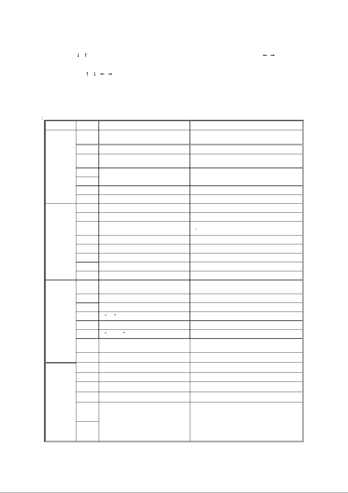
3.1
Function Description for Bus Data (CH08T0608)
Table 3
Bit Function Description Status
Audio system options (available during auto search
and use of AUTO button)
V MUTE
SECAM
Step length setting for lighting up gradually during
power-on
Default language option bit for AUTO button and
initialization
option in SOUND menu 0: No 1: Yes
00: B/G 01: I 10: D/K 11: M
1: Audio system switchover (Defined as game player control for
CH08T0608) 0: External mute
When changing channels: 0: Y- mute 1: RGB mute
0: No 1:Yes
1 Large step 0: Small step
0: Chinese 1: English
0: Short time 1: If OPT.2 = 1, long time; OPT.2 = 0, short
time
MODE0
MODE1
MODE2
Bit7.6
Bit5 Control program of new small characters 1:Yes 0: No
Bit4 Function description for CPU’s Pin 61
Bit3
Bit2
Bit1 Fixed to 0
Bit0 Power-on modes 0: Memory on 1: Soft on
Bit7 Write-in LOGO option 0: No 1:Yes
Bit6 Domestic NICAM or foreign NICAM? 0: Foreign 1: Domestic
Bit5
Bit4 Screen saver setting 0: No 1: Yes
Bit3 M option 0: No 1: Yes
Bit2 D/K option 0: No 1: Yes
Bit1 I option 0: No 1: Yes
Bit0 B/G option 0: No 1: Yes
Bit7
Bit6 DVD setting for AV board TC90L01 0: No 1: Yes
Bit5 Tilt correction setting 0: No 1: Yes
Bit4 SVM option in PICTURE menu 0: No 1: Yes
Bit 3 TA1343/NICAM woofer output setti ng 0: Mono output 1: Overlapped to main channel
Bit 2 WOOFER
Bit 1 Black-screen time setting
Bit.0 BBE AGC option 1: 300mv 0: 150mv
MODE3
BIT 7 Relay switch option 1: Yes 0: No
BIT 6 Instant power-on option 1: Yes 0: No
BIT 5.4 Fixed to 00
BIT 3 BBE/SRS IC 1: Yes 0: No
BIT 2
BIT 1
For TA1218,
multi AV switch options
BIT 0 BIT 1 BIT2
0 0 0 TV - AV1(S) - AV2 - AV3(S) - DVD
0 0 1 TV - AV1(S) - AV2 - AV3(S)
0 1 0 TV - AV1(S) - AV2 - DVD
0 1 1 TV - AV1(S) - AV2
(continued)
Page 3
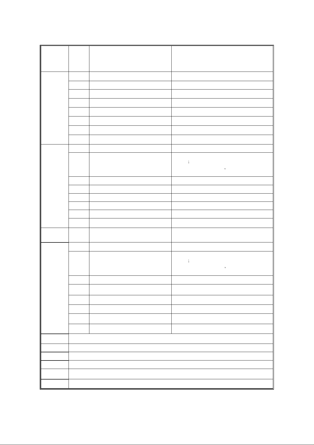
BIT 0
BIT 7 TC90A49 option 0: No 1: Yes
BIT 6 TA1343 option 0: No 1: Yes
MODE4
OPT
LANG-OUT Ex-factory language options w ith AUTO key 00: English 01: French 02: German 03: Russian
OPT
BIT 5 TC90L01 option 0: No 1: Yes
BIT 4 TA1218 option 0: No 1: Yes
BIT 3 MSP3410 option (NICAM) 0: No 1: Yes
BIT 2 NJW1161 option 0: No 1: Yes
BIT 1 NJW1160 option 0: No 1: Yes
BIT 0 NJW1137 option 0: No 1: Yes
Bit 7 Interval between relay on and off 0: No 1: Yes
Bit 6 VCO adjustments
Bit 5 SOUND Menu option 1: Yes 0: No
Bit 4 Large-amplitude AFT on/off when no signal 1: Off 0: On
Bit 3 Audio gain switch 1: Off 0: On
Bit 2 Usage of Y-mute 0: No 1: Yes
Bit 1 Single language 1: Yes 0: No
Bit 0 Single audio system 1: Yes 0: No
Bit 7 Interval between relay on and off 0: No 1: Yes
Bit 6 VCO adjustments 0: PIF VCO functions (PIFVCO = 10) during auto search and
Bit 5 Audio processing 1: Yes 0: No
Bit 4 Large-amplitude AFT switch when no signal 1: Off 0: On
Bit 3 Audio gain switch 1: Off 0: On
Bit 2 Usage of Y-mute 0: No 1: Yes
Bit 1 Thailand B/G (5.74M) 1: Yes 0: No
1 0 0 TV - AV1(S) - AV3(S) - DVD
1 0 1 TV - AV1(S) - AV3(S)
1 1 0 TV - AV1(S) - DVD
1 1 1 TV - AV1
0: PIF VCO functions (PIFVCO = 10) during auto search and
search
1: PIFVCO = 10 during turn-on
mode
04: Indonesian 05: Malay 06: Farsi 07: Arabic
search
1: PIFVCO = 10 during turn-on
mode
and PIFVCO = 00 in Normal
and PIFVCO = 00 in Normal
Bit 0 Single audio system 1: Yes 0: No
OSD Horizontal position of OSD
RCUT R cut off
GCUT G cut off
BCUT B cut off
GDRV G drive
BDRV B drive
(continued)
Page 4

CNTX Contrast Max.
BRTC Brightness center
COLC Color center ( f or NTSC)
TNTC Tint center (for NTSC)
TNTCAV Tint center (for NTS C IN AV)
COLP Color center (for PAL)
COLS Color center (for SEC AM)
DCOL DVD color
SCOL Sub color center (for DVD )
SCNT Y- sub contrast
CNTC Contrast center
CNTN Contrast Min.
BRTX Brightness Max.
BRTN Brightness Min.
COLX Color Max.
COLN Color Min.
TNTX Tint Max.
TNTN Tint Min.
ST3 Sharpness center for NTSC 3.58 (TV)
SV3 Sharpness center f or NTSC 3.58 (VIDEO)
ST4 Sharpness center for other color syst em ( TV)
SV4 Sharpness center for other color system (VIDEO)
SVD Sub Sharpness center in DVD
ASSH Asymmetry sharpness
SHPX Sharpness Max.
SHPN Sharpness Min.
TXCX Text RGB in user contrast Max.
RGCN Text RGB in user contrast Min.
ABL
DCBS
BIT 5 Y peak limiter 0: Off 1: On
BIT 4 OSD ABL 0: Active 1: Inactive
BIT 3.2 ABL start point
BIT 1.0 ABL gain
BIT 7 Blank SW 0: H, V blanking on 1: H, V blanking off
Bit 6
Bit 5.4 OSD level
Bit 3.2 Y gamma
Bi t 1.0 Black stretch
00: ABL start point: 0V 01: -0.15V
10: -0.30V 11: -0.45V
00: -0.2V 01: -0.4V
10: -0.6V 11: -0.8V
00: OSD level, 80 IRE 01: 70IRE
10: 60IRE 11: 50IRE
00: Off 01: Y point 90 IRE, Gain –3dB
10: 80IRE 11: 70IRE
00: Off 01: Black stretch point, 25 IRE
10: 35IRE 11: 45IRE
(continued)
Page 5

CLTO
Chroma data
(TV & not M)
CLTM
(TV & M)
CLVD(DVD)
CLVO(50hz)
/CLVM
(VIDEO)
DEF BIT0 = 0: V AGC reference depends on YC VC C; BIT0 = 1: V AGC reference depends on integrated regulator
SECD No use
HPOS 50Hz horizont al phase
VP50 V phase (50Hz)
HIT V size
HPS Adjusting difference between horizontal centers in PAL and NTSC
VP60 V phase (60Hz)
HITS
VLIN V-linearity
VSC V-S correction
VLIS
VSS
DPC EW parabola
DPCS
HIT69
DPC69
HIT69S
DPC69S
KEY Trapezium
KEYS
WID H size
WIDS
ECCT EW corner top
ECCB EW corner bottom
VEHT V EHT gain
HEHT H EHT gain
SBY Use in SECAM
BIT 7 Killer off
BIT 6 P/N ID
BIT 5 C gamma 0: Color gamma off 1: On
BIT 4.3 NTSC matrix
BIT 2.1.0 Y DL
60hz
Adjusting difference bet w een vertical amplitudes in PAL and NTSC
Adjusting difference between vertical linear in PA L and N TSC
Correction for shift data of 50 Hz/ 60 Hz
Shift data of EW parabola
Vertical amplitude in 16:9 mode (PAL)
EW parabola 16:9 in 16:9 mode (PA L)
Vertical amplitude in 16:9 mode (NTSC)
EW parabola 16:9 in 16:9 mode (NTS C)
Shift data of trapezium
Shift data of H size
0: Normal 1: Always killer off
0: PAL/ NTSC killer sensitivity, 1mVpp 1: 10mVpp
00: USA (105 degree) 01: Japan (93 degree)
10: DVD 11:
000: -40 nsec 001: 0 010: 40 nsec 011: 80 nsec
100: 120 nsec 101: 160 nsec 110: 200 nsec 111: 240 nsec
00: -3usec 10: 0 1F: +3usec
0: V phase delay, 0H 7: 7H
00: -50% 20: 0% 3F: 50%
0: V phase delay, 0H 7: 7H
0: -15% 8: 0% F: 15%
0: -16% 8: 0% F: 16%
00: 0Vpp 20: 1.4Vpp 3F: 2.8Vpp
00: -13% 20: 0% 3F: 13%
00: 1.5V V20: 4V 3F: 6.5V
00: -1.5V 10: 0V 1F: 1.5V
00: -1.5V 10: 0V 1F: 1.5V
0: 0% 4: 5% 7: 10%
0: 0% 4: 5% 7: 10%
(continued)
Page 6

SRY Use in SECAM
BRTS
RFAGC RF AGC
HAFC
V01 Volume output data at 1%
V25 Volume output data at 25%
V50 Volume output data at 50%
V100 Volume output data at 100%
Woofer TA1343 woofer Max.
STAT No use
FLG0
FLG1
REFP AKB pulse position
RSNS R SENSE 00: x 0 20: x 0.5 3F: x 1.0
Sub brightness (difference)
BIT 3.2
BIT 1.0
BIT 7 Readjust VCO when select ing position 0: Enable 1: Disable
BIT 2 N buzz cancel 0: Nyquist buzz cancel, on 1: Off
BIT 1 AFT window SW
BIT 0 Over modulation 0: Normal 1: PIF over modulation switch on
BIT 5 MIX GAIN 0: SIF 1MHz convert gain, low gain 1: High gain
BIT 4 Sync separation. 0: Sync separation level 40% 1: 36%
AFC gain
(in VIDEO mode)
AFC gain
(in TV mode)
00: IF mute 01: 65dBu 3F: 100dBu
Data Description
Blanking Period Picture Period
0 0 3 1
0 1 4/7 2/7
1 0 4/3 1
1 1 Off Off
Data Description
Blanking Period Picture Period
0 0 3 1
0 1 4/7 2/7
1 0 4/3 1
1 1 Off Off
0: Wide (-/+ 250kHz) AFT sensitivity, for channel search
1: Narrow (83kHz) For normal operation
000: 0H 001: 1H 010: 2H 011: 3H
100: 4H 101: 5H 110: 6H 111: 7H
GSNS G SENSE 00: x 0 20: x 0.5 3F: x 1.0
BSNS B SENSE 00: x 0 20: x 0.5 3F: x 1.0
MOD
STBY
SVM BIT.4
SVM1 Data when SVM off
SVM3 Data when SVM on
VBLK
VCEN Vertical centering
Bit 6.5.4 PIF FREQUENCY 001: 45.75 MHz 011: 38.9 MHz 100: 38.0 MHz
Bit 1.0 AKB MODE
BIT 3.2 VCD STANDBY
BIT 1.0 IF Standby
BIT 3.2 V blanking stop point
BIT 1.0 V blanking start point
00: AKB off 01: ACB (cutoff: align to targets)
10: ADB (drive: align to targets) 11: AKB (cutoff/drive: align to targets)
00: Normal 01: Normal
10: Normal 11: VCD Standby
00: Normal 01: Normal
10: Normal 11: IF Standby
1:co max=1
-0.65 to +0.65)
00: 310H(50hz) 263H(60hz) 01: 299H(50hz) 254H(60hz)
10: 295H(50hz) 250H(60hz) 11: 291H(50hz) 246H(60hz)
00: 23H(50hz) 22H(60hz) 01: 33H (50hz)30H(60hz)
10: 37H (50hz)34H(60hz) 11: 41H(50hz) 38H(60hz)
00: -32% 20: 0% 3F: 30%
-0.65 to +0.85 0: co max=0 cutoff range:
(continued)
Page 7

UCOM
VTST No use
PYNX Normal H.SYNC Max. 0-----------3F
PYNN Normal H.SYNC Min. 0-----------3F
PYXS ASM/Search H.SYNC Max. 0-----------3F
PYNS ASM/Search H.SYNC Min 0-----------3F
BASC Bass volume Center
BASX Bass volume Max.
TREC Treble volume Center
BALC Balance volume Center
BAS1 Bass in MUSIC mode setting
TRE1 Treble in MUSIC mode setting
WFL1 Woofer in MUSIC mode setting
BAS2 Bass in NEWS mode setting
TRE2 Treble in NEWS mode setting
WFL2 Woofer in NEWS mode setting
BIT 1.0 Internal ADC
BIT5.4.3
Improving NTSC color signal-to-noise
ratio
00: GND 01: R output
10: B output 11: Monitor RF AGC via ADC
Available range: 000….011
BAS3 Bass in THEATRE mode setting
TRE3 Treble in THEATRE mode setting
WFL3 Woofer in THEATRE mode setting
WON1 TA1343 Max. woofer setting. The bigger the setting the smaller Max. woofer.
WON2 Woofer linear setting
NVOL Prescale NICAM
NICL NICAM->MONO level
NICH MONO->NICAM level
NOIS
VATT Audio ATT 00:-85DB or less 7F:0DB (7 BITS)
COM1
(TC90A49)
COM2
(TC90A49)
B1(12345)
B2(12345)
B3(12345)
BBE Highest four bits BBE contour (0dB to 15dB); Lowest four bits: BBE process (0dB to 15dB)
OSDF OSD frequency setting
BIT 2
BIT 7-BIT 0
BIT 3 Pedestal clip 0: On 1: Off
BIT 2.1.0 VENH2.1.0 000: 0db(x1) …… 111: 3.52db(x1.5)
BIT 7.6.5.4 Set vertical enhancer non-linear point 0000: 4LSB …… 1111: 64LSB
BIT 3 Set Y output horizontal peaking gain 0: 1.5dB 1: 3.0dB
BIT2 Set Y output horizontal peaking on/off 0: On 1: Off
BIT 1.0 Set vertical enhancer coring level 00: 0LSB …… 11: 3LSB
NICAM chip five-equalizer data when the sound mode set to MUSIC:
B11 (for 120Hz) B12 (for 500 Hz) B13 (for 1.5KHz) B14 (for 5KHz) B15 (for 10KHz)
NICAM chip five-equalizer data when the sound mode set to NEWS:
B21 (for 120Hz) B22 (for 500 Hz) B23 (for 1.5KHz) B24 (for 5KHz) B25 (for 10KHz)
NICAM chip five-equalizer data when the sound mode set to THEATRE:
B31(for 120Hz) B32 (for 500 Hz) B33 (for 1.5KHz) B34 (for 5KHz) B35 (for 10KHz)
AFC gain data setting in TV mode: 1: Adjust AFC gain in the lowest two bits of HAFC 0: With weak signal
received, AFC gain = 0x10; with strong signal received, AFC gain = 0x00
Criterion of signal strength: >NOIS: Weak signal
<= NOIS: Strong signal
Page 8

3.2 Adjustments and Bus data (CH08T0608)
Table 4
Item Data Item Data Item Data Item Data
* MODE0 80 COLS 40 # HITS 04 STBY 00
* MODE1 3E DCOL 40 # VLIN 09 SVM 00
* MODE2 5B SCOL 00 # VSC 0A SVM1 00
* MODE3 08 SCNT 09 # VLIS 00 SVM3 06
* MODE4 21 CNTC 40 # VSS 01 VBLK 00
COM1 04 CNTN 08 # HIT69 14 # VCEN 20
COM2 3F BRTX 20 # DPC69 10 UCOM 00
EQU11 5A BRTN 20 # DPC 18 VTST 00
EQU12 5A COLX 20 # KEY 22 PYNX 2E
EQU13 46 COLN 00 # WID 0F PYNN 18
EQU14 5A TNTX 28 # HIT69S 01 PYXS 22
EQU15 5A TNTN 28 # DPC9S 01 PYNS 1E
EQU21 32 ST3 30 # DPCS 03 BASC 40
EQU22 3C SV3 30 # KEYS 00 BASX 70
EQU23 3C ST4 28 # WIDS 02 TREC 40
EQU24 3C SV4 30 # ECCT 08 BALC 40
EQU25 32 SVD 30 # ECCB 08 BAS1 3C
EQU31 46 ASSH 07 VEHT 04 TRE1 40
EQU32 46 SHPX 10 HEHT 01 WFL1 46
EQU33 3C SHPN 10 # SBY 08 BAS2 20
EQU34 46 TXCX 3F # SRY 08 TRE2 50
EQU35 46 RGCN 1F # BRTS 17 WFL2 00
BBE 9B ABL 21 # RAGC 18 BAS3 20
OSDF 63 DCBS 16 HAFC 08 TRE3 40
# OSD 19 CLTO 3F * V01 35 WFL3 20
* OPT 20 * CLTM 23 * V25 60 * WON1 00
# RCUT 30 CLVO 3F * V50 70 WON2 00
# GCUT 30 * CLVM 20 * V100 7F * FVOL 13
# BCUT 30 CLVD 30 * WOOFER 7F NVOL 7F
# GDRV 40 DEF 01 STAT 00 EVOL 12
# BDRV 40 AKB 00 FLG0 06 NICL 0A
CNTX 7F SECD 08 FLG1 18 NICH 17
# BRTC 40 # HPOS 0B REFP 00 NOIS 01
COLC 28 # VP50 04 RSNS 00 VATT 5D
TNTC 30 # HIT 1F GSNS 00
TNTCAV 48 # HPS 03 BSNS 00
COLP 00 # VP60 02 MOD 40
Notes:
The data sheet may differ dependent on different models.
The data sheet may differ dependent on different CRTs for the same model.
The data marked with
* can be adjusted.
 Loading...