

Page 1

P5VDC-MX
Motherboard
Page 2

E2277E2277
E2277
E2277E2277
First EditionFirst Edition
First Edition
First EditionFirst Edition
October 2005October 2005
October 2005
October 2005October 2005
Copyright © 2005 ASUSTeK COMPUTER INC. All Rights Reserved.
No part of this manual, including the products and software described in it, may be reproduced,
transmitted, transcribed, stored in a retrieval system, or translated into any language in any form
or by any means, except documentation kept by the purchaser for backup purposes, without the
express written permission of ASUSTeK COMPUTER INC. (“ASUS”).
Product warranty or service will not be extended if: (1) the product is repaired, modified or
altered, unless such repair, modification of alteration is authorized in writing by ASUS; or (2)
the serial number of the product is defaced or missing.
ASUS PROVIDES THIS MANUAL “AS IS” WITHOUT WARRANTY OF ANY KIND, EITHER
EXPRESS OR IMPLIED, INCLUDING BUT NOT LIMITED TO THE IMPLIED WARRANTIES
OR CONDITIONS OF MERCHANTABILITY OR FITNESS FOR A PARTICULAR PURPOSE.
IN NO EVENT SHALL ASUS, ITS DIRECTORS, OFFICERS, EMPLOYEES OR AGENTS BE
LIABLE FOR ANY INDIRECT, SPECIAL, INCIDENTAL, OR CONSEQUENTIAL DAMAGES
(INCLUDING DAMAGES FOR LOSS OF PROFITS, LOSS OF BUSINESS, LOSS OF USE
OR DATA, INTERRUPTION OF BUSINESS AND THE LIKE), EVEN IF ASUS HAS BEEN
ADVISED OF THE POSSIBILITY OF SUCH DAMAGES ARISING FROM ANY DEFECT OR
ERROR IN THIS MANUAL OR PRODUCT.
SPECIFICATIONS AND INFORMATION CONTAINED IN THIS MANUAL ARE FURNISHED
FOR INFORMATIONAL USE ONLY, AND ARE SUBJECT TO CHANGE AT ANY TIME
WITHOUT NOTICE, AND SHOULD NOT BE CONSTRUED AS A COMMITMENT BY ASUS.
ASUS ASSUMES NO RESPONSIBILITY OR LIABILITY FOR ANY ERRORS OR
INACCURACIES THAT MAY APPEAR IN THIS MANUAL, INCLUDING THE PRODUCTS
AND SOFTWARE DESCRIBED IN IT.
Products and corporate names appearing in this manual may or may not be registered
trademarks or copyrights of their respective companies, and are used only for identification or
explanation and to the owners’ benefit, without intent to infringe.
iiii
ii
iiii
Page 3

Contents
Notices ................................................................................................ vi
Safety information ............................................................................. vii
About this guide ............................................................................... viii
P5VDC-MX specifications summary ..................................................... x
Chapter 1: Product introductionChapter 1: Product introduction
Chapter 1: Product introduction
Chapter 1: Product introductionChapter 1: Product introduction
1.1 Welcome! .............................................................................. 1-2
1.2 Package contents ................................................................. 1-2
1.3 Special features .................................................................... 1-2
1.3.1 Product highlights ................................................... 1-2
1.3.2 Innovative ASUS features ....................................... 1-4
1.4 Before you proceed .............................................................. 1-5
1.5 Motherboard overview .......................................................... 1-6
1.5.1 Placement direction ................................................ 1-6
1.5.2 Screw holes ............................................................ 1-6
1.5.3 Motherboard layout ................................................ 1-7
1.6 Central Processing Unit (CPU) .............................................. 1-8
1.6.1 Installling the CPU ................................................... 1-8
1.6.2 Installling the CPU heatsink and fan ..................... 1-11
1.6.3 Uninstalling the CPU heatsink and fan .................. 1-13
1.7 System memory ................................................................. 1-15
1.7.1 Overview ............................................................... 1-15
1.7.2 Memory Configurations ......................................... 1-15
1.7.3 DDR Qualified Vendors List ................................... 1-16
1.7.4 Installing a DDR DIMM (blue slots) ........................ 1-18
1.7.5 Removing a DDR DIMM .......................................... 1-18
1.7.6 Installing a DDR2 DIMM (yellow slots) .................. 1-19
1.7.7 Removing a DDR2 DIMM ........................................ 1-19
1.8 Expansion slots ................................................................... 1-20
1.8.1 Installing an expansion card .................................. 1-20
1.8.2 Configuring an expansion card .............................. 1-20
1.8.3 Interrupt assignments .......................................... 1-21
1.8.4 PCI slots ................................................................ 1-22
1.8.5 PCI Express x1 slot ............................................... 1-22
1.8.6 AGP slot ................................................................ 1-22
iiiiii
iii
iiiiii
Page 4

Contents
1.9 Jumpers .............................................................................. 1-23
1.10 Connectors .........................................................................1-25
1.10.1 Rear panel connectors .......................................... 1-25
1.10.2 Internal connectors ...............................................1-26
Chapter 2: BIOS setupChapter 2: BIOS setup
Chapter 2: BIOS setup
Chapter 2: BIOS setupChapter 2: BIOS setup
2.1 Managing and updating your BIOS ........................................ 2-2
2.1.1 Creating a bootable floppy disk .............................. 2-2
2.1.2 ASUS EZ Flash utility .............................................. 2-3
2.1.3 AFUDOS utility ........................................................ 2-4
2.1.4 ASUS CrashFree BIOS 2 utility ................................ 2-6
2.1.5 ASUS Update utility ................................................ 2-8
2.2 BIOS setup program ........................................................... 2-11
2.2.1 BIOS menu screen ................................................. 2-12
2.2.2 Menu bar ............................................................... 2-12
2.2.3 Navigation keys .................................................... 2-12
2.2.4 Menu items ...........................................................2-13
2.2.5 Sub-menu items ................................................... 2-13
2.2.6 Configuration fields .............................................. 2-13
2.2.7 Pop-up window ..................................................... 2-13
2.2.8 Scroll bar .............................................................. 2-13
2.2.9 General help .......................................................... 2-13
2.3 Main menu .......................................................................... 2-14
2.3.1 System Time [xx:xx:xxxx] .....................................2-14
2.3.2 System Date [Day xx/xx/xxxx] ............................2-14
2.3.3 Legacy Diskette A [1.44M, 3.5 in.]......................2-14
2.3.4 Primary and Secondary IDE Master/Slave ............. 2-15
2.3.5 System Information ..............................................2-16
2.4 Advanced menu .................................................................. 2-17
2.4.1 JumperFree Configuration ....................................2-17
2.4.2 USB Configuration ................................................. 2-18
2.4.3 CPU Configuration ................................................. 2-19
2.4.4 Chipset ................................................................. 2-20
2.4.5 Onboard Devices Configuration ............................ 2-24
iviv
iv
iviv
Page 5

Contents
2.4.6 PCI PnP ................................................................. 2-25
2.5 Power menu ........................................................................ 2-27
2.5.1 Suspend Mode [Auto] .......................................... 2-27
2.5.2 Repost Video on S3 Resume [No] ........................2-27
2.5.3 ACPI 2.0 Support [No] ......................................... 2-27
2.5.4 ACPI APIC Support [Enabled] ................................ 2-27
2.5.5 APM Configuration ................................................ 2-28
2.5.6 Hardware Monitor ................................................. 2-29
2.6 Boot menu .......................................................................... 2-30
2.6.1 Boot Device Priority .............................................. 2-30
2.6.2 Boot Settings Configuration .................................2-31
2.6.3 Security ................................................................ 2-32
2.7 Exit menu ........................................................................... 2-34
Chapter 3: Software supportChapter 3: Software support
Chapter 3: Software support
Chapter 3: Software supportChapter 3: Software support
3.1 Installing an operating system ............................................. 3-2
3.2 Support CD information ........................................................ 3-2
3.2.1 Running the support CD ......................................... 3-2
3.2.2 Drivers menu .......................................................... 3-3
3.2.3 Utilities menu .......................................................... 3-4
3.2.4 Make Disk menu ...................................................... 3-5
3.2.5 Manuals menu ......................................................... 3-5
3.2.6 ASUS Contact information ...................................... 3-6
3.3 RAID configurations .............................................................. 3-7
3.3.1 Installing hard disks ................................................ 3-8
3.4 Creating a RAID driver disk ................................................. 3-12
vv
v
vv
Page 6

Notices
Federal Communications Commission StatementFederal Communications Commission Statement
Federal Communications Commission Statement
Federal Communications Commission StatementFederal Communications Commission Statement
This device complies with Part 15 of the FCC Rules. Operation is subject to
the following two conditions:
•
This device may not cause harmful interference, and
•
This device must accept any interference received including interference
that may cause undesired operation.
This equipment has been tested and found to comply with the limits for a
Class B digital device, pursuant to Part 15 of the FCC Rules. These limits are
designed to provide reasonable protection against harmful interference in a
residential installation. This equipment generates, uses and can radiate radio
frequency energy and, if not installed and used in accordance with
manufacturer’s instructions, may cause harmful interference to radio
communications. However, there is no guarantee that interference will not
occur in a particular installation. If this equipment does cause harmful
interference to radio or television reception, which can be determined by
turning the equipment off and on, the user is encouraged to try to correct
the interference by one or more of the following measures:
•
Reorient or relocate the receiving antenna.
•
Increase the separation between the equipment and receiver.
•
Connect the equipment to an outlet on a circuit different from that to
which the receiver is connected.
•
Consult the dealer or an experienced radio/TV technician for help.
The use of shielded cables for connection of the monitor to the graphics
card is required to assure compliance with FCC regulations. Changes or
modifications to this unit not expressly approved by the party
responsible for compliance could void the user’s authority to operate
this equipment.
Canadian Department of Communications StatementCanadian Department of Communications Statement
Canadian Department of Communications Statement
Canadian Department of Communications StatementCanadian Department of Communications Statement
This digital apparatus does not exceed the Class B limits for radio noise
emissions from digital apparatus set out in the Radio Interference
Regulations of the Canadian Department of Communications.
This class B digital apparatus complies with CanadianThis class B digital apparatus complies with Canadian
This class B digital apparatus complies with Canadian
This class B digital apparatus complies with CanadianThis class B digital apparatus complies with Canadian
ICES-003.ICES-003.
ICES-003.
ICES-003.ICES-003.
vivi
vi
vivi
Page 7

Safety information
Electrical safetyElectrical safety
Electrical safety
Electrical safetyElectrical safety
•
To prevent electrical shock hazard, disconnect the power cable from
the electrical outlet before relocating the system.
•
When adding or removing devices to or from the system, ensure that
the power cables for the devices are unplugged before the signal cables
are connected. If possible, disconnect all power cables from the existing
system before you add a device.
•
Before connecting or removing signal cables from the motherboard,
ensure that all power cables are unplugged.
•
Seek professional assistance before using an adapter or extension cord.
These devices could interrupt the grounding circuit.
•
Make sure that your power supply is set to the correct voltage in your
area. If you are not sure about the voltage of the electrical outlet you
are using, contact your local power company.
•
If the power supply is broken, do not try to fix it by yourself. Contact a
qualified service technician or your retailer.
Operation safetyOperation safety
Operation safety
Operation safetyOperation safety
•
Before installing the motherboard and adding devices on it, carefully read
all the manuals that came with the package.
•
Before using the product, make sure all cables are correctly connected
and the power cables are not damaged. If you detect any damage,
contact your dealer immediately.
•
To avoid short circuits, keep paper clips, screws, and staples away from
connectors, slots, sockets and circuitry.
•
Avoid dust, humidity, and temperature extremes. Do not place the
product in any area where it may become wet.
•
Place the product on a stable surface.
•
If you encounter technical problems with the product, contact a qualified
service technician or your retailer.
This symbol of the crossed out wheeled bin indicates that the product
(electrical and electronic equipment) should not be placed in municipal
waste.
Please check local regulations for disposal of electronic products.
viivii
vii
viivii
Page 8

About this guide
This user guide contains the information you need when installing and
configuring the motherboard.
How this guide is organizedHow this guide is organized
How this guide is organized
How this guide is organizedHow this guide is organized
This manual contains the following parts:
••
Chapter 1: Product introductionChapter 1: Product introduction
•
Chapter 1: Product introduction
••
Chapter 1: Product introductionChapter 1: Product introduction
This chapter describes the features of the motherboard and the new
technology it supports. This chapter also lists the hardware setup
procedures that you have to perform when installing system
components. It includes description of the jumpers and connectors on
the motherboard.
••
Chapter 2: BIOS setupChapter 2: BIOS setup
•
Chapter 2: BIOS setup
••
Chapter 2: BIOS setupChapter 2: BIOS setup
This chapter tells how to change system settings through the BIOS
Setup menus. Detailed descriptions of the BIOS parameters are also
provided.
••
Chapter 3: Software supportChapter 3: Software support
•
Chapter 3: Software support
••
Chapter 3: Software supportChapter 3: Software support
This chapter describes the contents of the support CD that comes
with the motherboard package.
Where to find more informationWhere to find more information
Where to find more information
Where to find more informationWhere to find more information
Refer to the following sources for additional information and for product
and software updates.
1.1.
ASUS websitesASUS websites
1.
ASUS websites
1.1.
ASUS websitesASUS websites
The ASUS website provides updated information on ASUS hardware
and software products. Refer to the ASUS contact information.
2.2.
Optional documentationOptional documentation
2.
Optional documentation
2.2.
Optional documentationOptional documentation
Your product package may include optional documentation, such as
warranty flyers, that may have been added by your dealer. These
documents are not part of the standard package.
viiiviii
viii
viiiviii
Page 9

Conventions used in this guideConventions used in this guide
Conventions used in this guide
Conventions used in this guideConventions used in this guide
To make sure that you perform certain tasks properly, take note of the
following symbols used throughout this manual.
DANGER/WARNING: DANGER/WARNING:
DANGER/WARNING: Information to prevent injury to yourself
DANGER/WARNING: DANGER/WARNING:
when trying to complete a task.
CAUTION:CAUTION:
CAUTION: Information to prevent damage to the components
CAUTION:CAUTION:
when trying to complete a task.
IMPORTANT: IMPORTANT:
IMPORTANT: Instructions that you MUST follow to complete a
IMPORTANT: IMPORTANT:
task.
NOTE: NOTE:
NOTE: Tips and additional information to help you complete a
NOTE: NOTE:
task.
Typography
Bold textBold text
Bold text Indicates a menu or an item to select
Bold textBold text
Italics
<Key> Keys enclosed in the less-than and greater-than sign means
<Key1+Key2+Key3> If you must press two or more keys simultaneously, the
Command Means that you must type the command exactly as shown,
Used to emphasize a word or a phrase
that you must press the enclosed key
Example: <Enter> means that you must press the Enter or
Return key
key names are linked with a plus sign (+)
Example: <Ctrl+Alt+D>
then supply the required item or value enclosed in
brackets
Example: At the DOS prompt, type the command line:
afudos /i[filename]
afudos /iP5VDCMX.ROM
ixix
ix
ixix
Page 10

P5VDC-MX specifications summary
CPUCPU
CPU
CPUCPU
ChipsetChipset
Chipset
ChipsetChipset
Front Side BusFront Side Bus
Front Side Bus
Front Side BusFront Side Bus
MemoryMemory
Memory
MemoryMemory
Expansion slotsExpansion slots
Expansion slots
Expansion slotsExpansion slots
VGAVGA
VGA
VGAVGA
StorageStorage
Storage
StorageStorage
LGA775 socket for Intel® Pentium® D/Pentium® 4/
Celeron CPU Compatible with Intel®
04A processor
Supports Intel® EM64T/Hyper-Threading Technology
(Note: Due to chipset limitation, the Intel Enhanced Intel
SpeedStep Technology, C1E, and TM2 are not
supported in this model)
Northbridge: VIA P4M800 PRO
Southbridge: VIA VT8251
800/533 MHz
2 x 240-pin DIMM sockets support max. 2GB DDR2
533/400 non-ECC, unbuffered memory.
2 x 184-pin DIMM sockets support max. 2GB DDR 400/
333/266 non-ECC, unbuffered memory
(Note:DDR and DDR2 memory can not be used
simulltaneously)
1 x AGP 8X/4X (1.5V only)
1 x PCI Express x1
2 x PCI, PCI 2.2
Integrated VIA UniChrome Graphics, up to 128MB
shared memory
South Bridge: VT8251
2 x UltraDMA 133/100/66
4 x Serial ATA 3Gb/s with RAID 0, 1, 0+1 & JBOD
function
05B/05A and 04B/
LANLAN
LAN
LANLAN
AudioAudio
Audio
AudioAudio
Other ASUSOther ASUS
Other ASUS
Other ASUSOther ASUS
Special FeaturesSpecial Features
Special Features
Special FeaturesSpecial Features
Back panel I/OBack panel I/O
Back panel I/O
Back panel I/OBack panel I/O
PortsPorts
Ports
PortsPorts
xx
x
xx
Realtek RTL8201CL 10/100 LAN controller
Realtek ALC653 AC’97 6-channel Audio CODEC
ASUS Q-Fan
ASUS EZ Flash
CrashFree BIOS 2
ASUS MyLogo
1 x Parallel port
1 x RJ-45
4 x USB 2.0/1.1
1 x VGA out
1 x Serial port
1 x PS/2 keyboard
1 x PS/2 mouse
1 x 6-Channel Audio I/O
(continued on the next page)
Page 11

P5VDC-MX specifications summary
BIOSBIOS
BIOS
BIOSBIOS
ManageabilityManageability
Manageability
ManageabilityManageability
USBUSB
USB
USBUSB
Internal I/OInternal I/O
Internal I/O
Internal I/OInternal I/O
connectorsconnectors
connectors
connectorsconnectors
Form FactorForm Factor
Form Factor
Form FactorForm Factor
Support CDSupport CD
Support CD
Support CDSupport CD
contentscontents
contents
contentscontents
4 Mb Flash ROM, AMI BIOS, PnP, WfM2.0, DMI2.0,
SM BIOS 2.3
WOL by PME, WOR by PME, Chassis Intrussion, PXE, RPL
Max. 8 USB 2.0 ports
2 x USB 2.0/1.1 connector supports additional 4 USB
ports
4 x SATA connector
2 x IDE connector
CPU/Chassis fan connectors
Game/MIDI connector
24-pin EATX Power connector
4-pin ATX 12 V Power connector
CD/AUX audio-in connector
Chassis Intrusion
1 x Floppy disk drive connector
1 x S/PDIF out connector
Front panel audio connector
System panel connector
mATX Form Factor, 9.6 in x 9.6 in (24.5 cm x 24.5 cm)
Drivers
ASUS PC Probe
ASUS Live Update utility
Anti-virus software (OEM version)
*Specifications are subject to change without notice.
xixi
xi
xixi
Page 12

xiixii
xii
xiixii
Page 13

This chapter describes the motherboard
features and the new technologies
it supports.
introduction
Product
1
ASUS P5VDC-MXASUS P5VDC-MX
ASUS P5VDC-MX
ASUS P5VDC-MXASUS P5VDC-MX
1-11-1
1-1
1-11-1
Page 14

1.1 Welcome!
®®
®
Thank you for buying an ASUSThank you for buying an ASUS
Thank you for buying an ASUS
Thank you for buying an ASUSThank you for buying an ASUS
The motherboard delivers a host of new features and latest technologies,
making it another standout in the long line of ASUS quality motherboards!
Before you start installing the motherboard, and hardware devices on it,
check the items in your package with the list below.
®®
P5VDC-MX motherboard! P5VDC-MX motherboard!
P5VDC-MX motherboard!
P5VDC-MX motherboard! P5VDC-MX motherboard!
1.2 Package contents
Check your motherboard package for the following items.
MotherboardMotherboard
Motherboard ASUS P5VDC-MX motherboard
MotherboardMotherboard
CablesCables
Cables 1 x Serial ATA power cable
CablesCables
1 x Serial ATA signal cable
1 x Ultra DMA 133/100 cables
1 x Floppy disk drive cable
AccessoriesAccessories
Accessories I/O shield
AccessoriesAccessories
Application CDsApplication CDs
Application CDs ASUS motherboard support CD
Application CDsApplication CDs
DocumentationDocumentation
Documentation User guide
DocumentationDocumentation
If any of the above items is damaged or missing, contact your retailer.
1.3 Special features
1.3.11.3.1
1.3.1
1.3.11.3.1
Latest processor technology Latest processor technology
Latest processor technology
Latest processor technology Latest processor technology
The motherboard comes with a 775-pin surface mount Land Grid Array
(LGA) socket designed for the Intel® Pentium® 4 processor in the 775-land
package. The motherboard supports the Intel® Pentium® 4 processor with
800 MHz Front Side Bus (FSB), and core speed of up to 3.8 GHz. The
motherboard also supports the Intel® Hyper-Threading Technology and is
fully compatible with Intel® 05B/05A and 04B/04A processors.
See page 1-8 for details.
1-21-2
1-2
1-21-2
Product highlightsProduct highlights
Product highlights
Product highlightsProduct highlights
Chapter 1: Product introductionChapter 1: Product introduction
Chapter 1: Product introduction
Chapter 1: Product introductionChapter 1: Product introduction
Page 15

64-bit CPU support 64-bit CPU support
64-bit CPU support
64-bit CPU support 64-bit CPU support
64-bit computing, the next generation technology to replace current 32-bit
architecture, delivers advanced system performance, faster memory access
and increased productivity. This motherboard provides excellent
compatibility and flexibility by supporting either 64-bit or 32-bit
architecture.
Dual-Core CPU Dual-Core CPU
Dual-Core CPU
Dual-Core CPU Dual-Core CPU
Enjoy the extraordinary CPU power from the latest dual-core CPU. The
advanced processing technology contains two physical CPU cores with
individually dedicated L2 cache to satisfy the rising demand for more
powerful processing capability.
AGP 8X support AGP 8X support
AGP 8X support
AGP 8X support AGP 8X support
The AGP 8X (AGP 3.0) VGA interface specification enables enhanced
graphics performance with high bandwidth speeds up to 2.12 GB/s.
Serial ATA II technology Serial ATA II technology
Serial ATA II technology
Serial ATA II technology Serial ATA II technology
The motherboard supports the Serial ATA II technology through the Serial
ATA interfaces and the VIA VT8251 chipset. The SATA specification allows
for thinner, more flexible cables with lower pin count, reduced voltage
requirement, and up to 300 MB/s data transfer rate. See page 1-28 for
details.
Onboard RAID solutionOnboard RAID solution
Onboard RAID solution
Onboard RAID solutionOnboard RAID solution
The onboard VIA VT8251 chipset allows RAID 0, RAID 1, RAID 0+1 and
JBOD configuration for four SATA connectors. Refer to page 3-7~3-12 for
details.
USB 2.0 technology USB 2.0 technology
USB 2.0 technology
USB 2.0 technology USB 2.0 technology
The motherboard implements the Universal Serial Bus (USB) 2.0
specification, dramatically increasing the connection speed from the 12
Mbps bandwidth on USB 1.1 to a fast 480 Mbps on USB 2.0. USB 2.0 is
backward compatible with USB 1.1. See page 1-24, 1-26, 1-31 for details.
ASUS P5VDC-MXASUS P5VDC-MX
ASUS P5VDC-MX
ASUS P5VDC-MXASUS P5VDC-MX
1-31-3
1-3
1-31-3
Page 16

AUDIO CODEC
The Realtek ALC653 is an AC”97 CODEC that allows 6-channel audio
playback. The audio CODEC provides six DAC channels for 5.1 surround
sound, AUX, and Line In stereo inputs.
1.3.21.3.2
1.3.2
1.3.21.3.2
CrashFree BIOS 2 CrashFree BIOS 2
CrashFree BIOS 2
CrashFree BIOS 2 CrashFree BIOS 2
This feature allows you to restore the original BIOS data from the support CD
in case when the BIOS codes and data are corrupted. This protection
eliminates the need to buy a replacement ROM chip. See details on page 2-6.
ASUS EZ Flash BIOS ASUS EZ Flash BIOS
ASUS EZ Flash BIOS
ASUS EZ Flash BIOS ASUS EZ Flash BIOS
With the ASUS EZ Flash, you can easily update the system BIOS even
before loading the operating system. No need to use a DOS-based utility or
boot from a floppy disk. See page 2-3 for details.
ASUS Q-Fan technology ASUS Q-Fan technology
ASUS Q-Fan technology
ASUS Q-Fan technology ASUS Q-Fan technology
The ASUS Q-Fan technology smartly adjusts the CPU fan speed according
to the system loading to ensure quiet, cool, and efficient operation. See
page 2-30 for deails.
Innovative ASUS featuresInnovative ASUS features
Innovative ASUS features
Innovative ASUS featuresInnovative ASUS features
1-41-4
1-4
1-41-4
Chapter 1: Product introductionChapter 1: Product introduction
Chapter 1: Product introduction
Chapter 1: Product introductionChapter 1: Product introduction
Page 17
1.4 Before you proceed
Take note of the following precautions before you install motherboard
components or change any motherboard settings.
• Unplug the power cord from the wall socket before touching any
component.
• Use a grounded wrist strap or touch a safely grounded object or to
a metal object, such as the power supply case, before handling
components to avoid damaging them due to static electricity
• Hold components by the edges to avoid touching the ICs on them.
• Whenever you uninstall any component, place it on a grounded
antistatic pad or in the bag that came with the component.
Before you install or remove any component, ensureBefore you install or remove any component, ensure
•
Before you install or remove any component, ensure
Before you install or remove any component, ensureBefore you install or remove any component, ensure
that the ATX power supply is switched off or thethat the ATX power supply is switched off or the
that the ATX power supply is switched off or the
that the ATX power supply is switched off or thethat the ATX power supply is switched off or the
power cord is detached from the power supply. power cord is detached from the power supply.
power cord is detached from the power supply. Failure
power cord is detached from the power supply. power cord is detached from the power supply.
to do so may cause severe damage to the motherboard, peripherals,
and/or components.
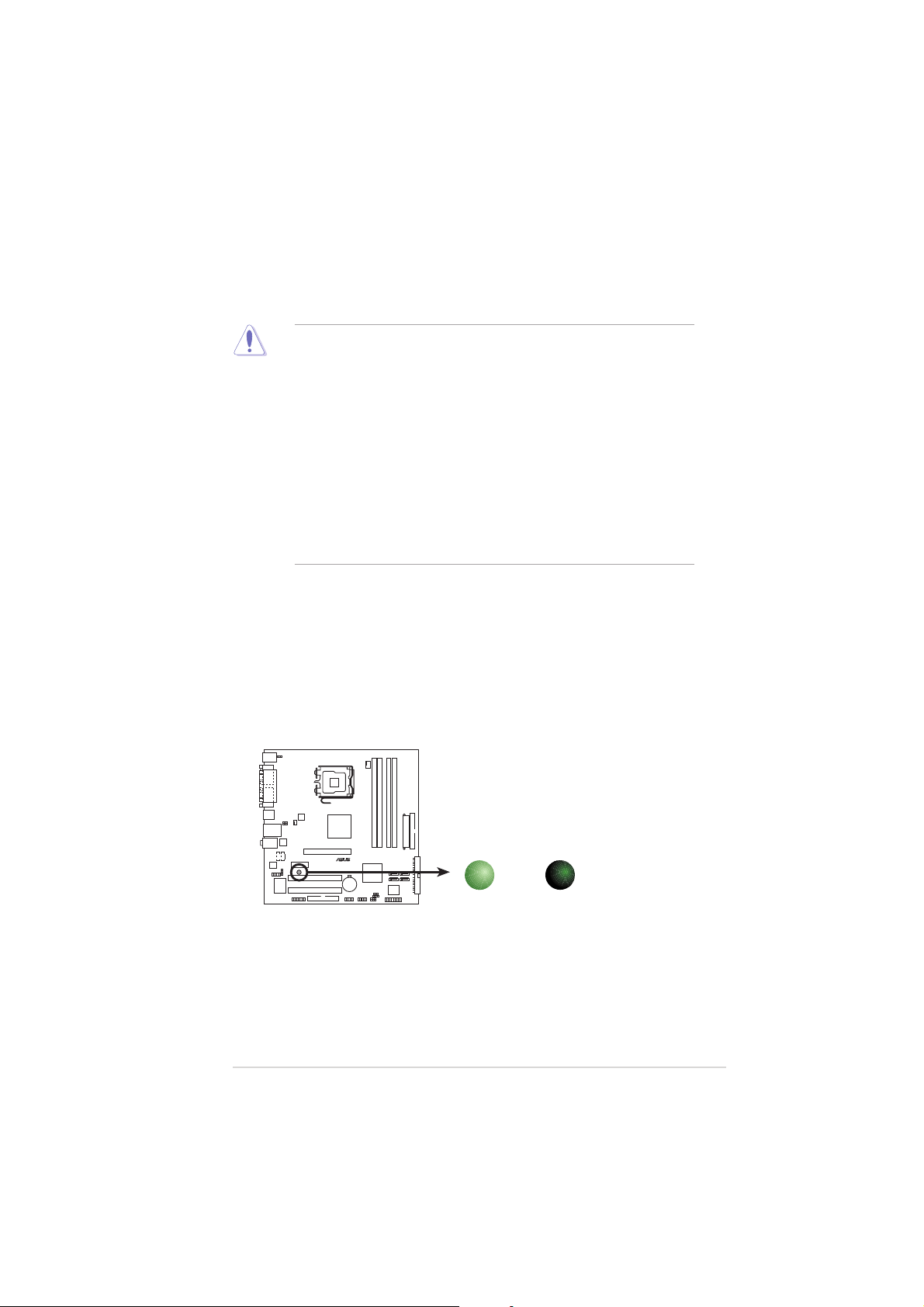
Onboard LEDOnboard LED
Onboard LED
Onboard LEDOnboard LED
The motherboard comes with a standby power LED that lights up to
indicate that the system is ON, in sleep mode, or in soft-off mode.
This is a reminder that you should shut down the system and unplug
the power cable before removing or plugging in any motherboard
component. The illustration below shows the location of the onboard
LED.
P5VDC-MX Onboard LED
ASUS P5VDC-MXASUS P5VDC-MX
ASUS P5VDC-MX
ASUS P5VDC-MXASUS P5VDC-MX
P5VDC-MX
®
ON
Standby
Power
SB_PWR
OFF
Powered
Off
1-51-5
1-5
1-51-5
Page 18
1.5 Motherboard overview
Before you install the motherboard, study the configuration of your chassis
to ensure that the motherboard fits into it.
Make sure to unplug the power cord before installing or removing the
motherboard. Failure to do so can cause you physical injury and damage
motherboard components.
1.5.11.5.1
1.5.1
1.5.11.5.1
Placement directionPlacement direction
Placement direction
Placement directionPlacement direction
When installing the motherboard, make sure that you place it into the
chassis in the correct orientation. The edge with external ports goes to the
rear part of the chassis as indicated in the image below.
1.5.21.5.2
1.5.2
1.5.21.5.2
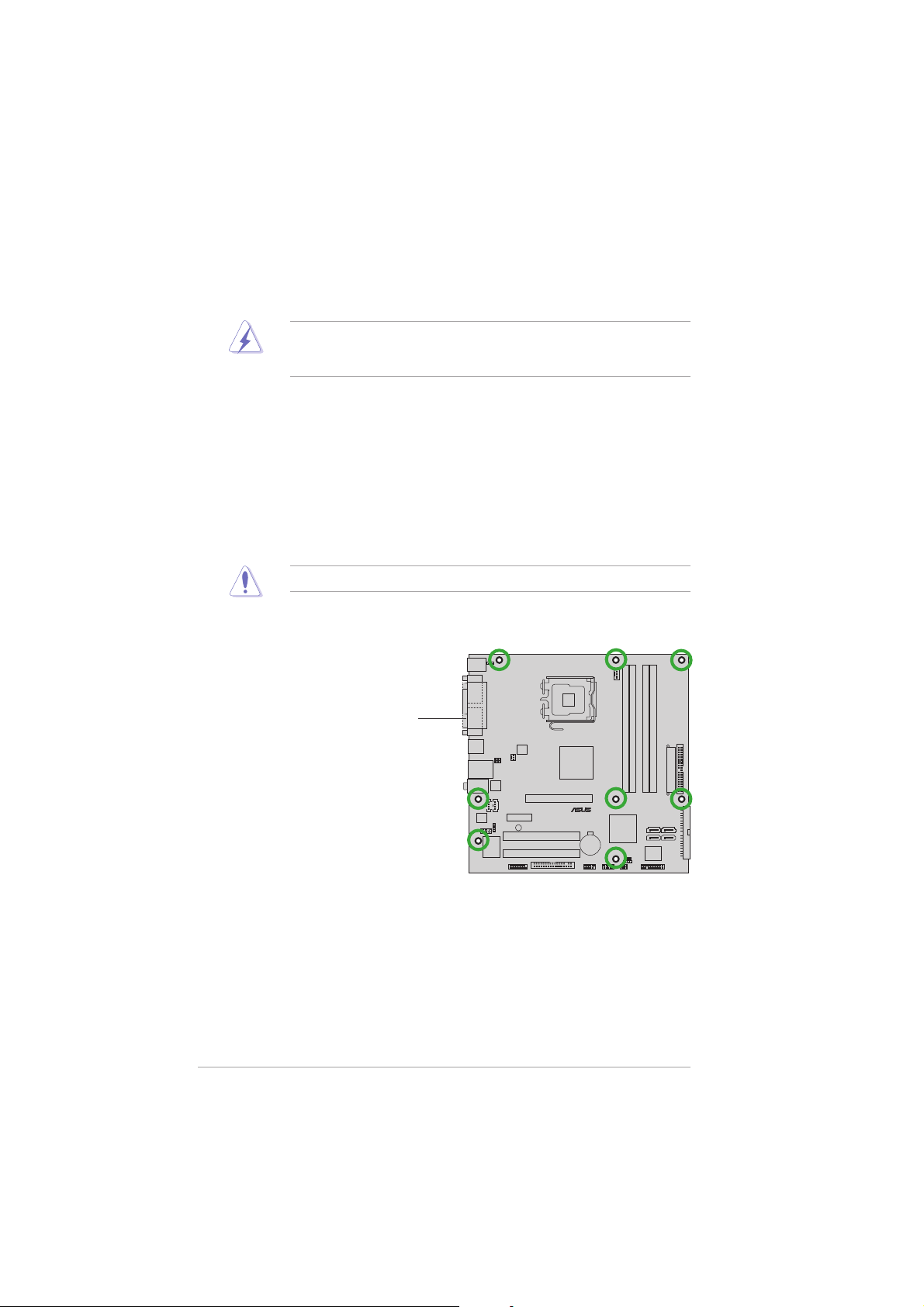
Screw holesScrew holes
Screw holes
Screw holesScrew holes
Place eight (8) screws into the holes indicated by circles to secure the
motherboard to the chassis.
Do not overtighten the screws! Doing so can damage the motherboard.
Place this side towardsPlace this side towards
Place this side towards
Place this side towardsPlace this side towards
the rear of the chassisthe rear of the chassis
the rear of the chassis
the rear of the chassisthe rear of the chassis
P5VDC-MX
®
1-61-6
1-6
1-61-6
Chapter 1: Product introductionChapter 1: Product introduction
Chapter 1: Product introduction
Chapter 1: Product introductionChapter 1: Product introduction
Page 19
1.5.31.5.3
1.5.3
1.5.31.5.3
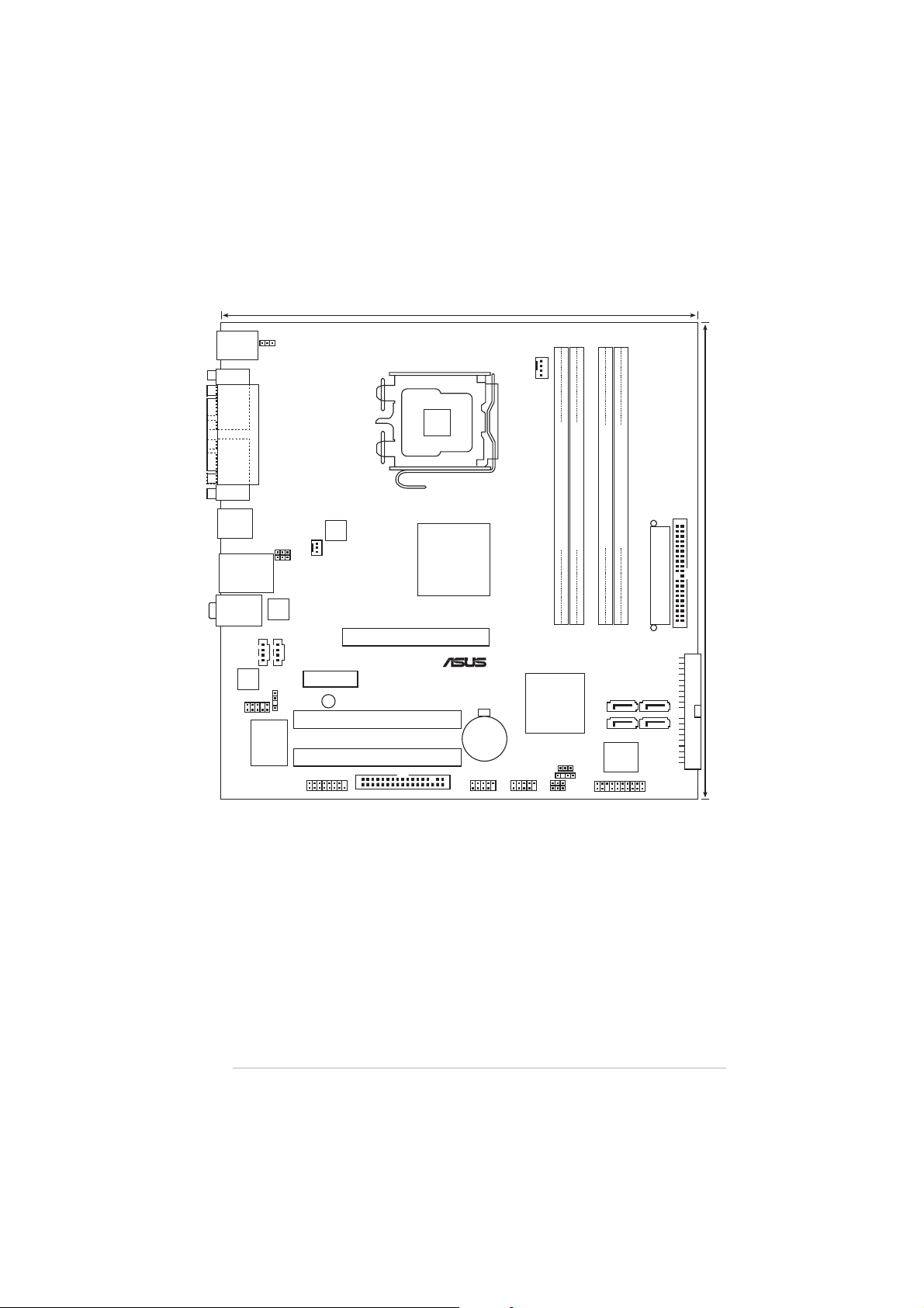
Motherboard layoutMotherboard layout
Motherboard layout
Motherboard layoutMotherboard layout
24.5cm (9.6in)
PS/2KBMS
T: Mouse
B: Keyboard
COM1
VGA
USB34
LAN_USB12
Top:Line In
Center:Line Out
Below:Mic In
ALC653
FP_AUDIO
PARALLEL PORT
KBPWR
USBPW12
USBPW34
RTL8201CL
SPDIF_OUT
I/O
Super
AUX1CD1
CHA_FAN
PCIEX1
GAME
ATX12V
SB_PWR
PCI1
PCI2
FLOPPY
LGA775
P4M800 PRO
AGP
VIA
®
CR2032 3V
Lithium Cell
CMOS Power
USB56
CPU_FAN
USB78
DDR2_2 (64 bit,240-pin module)
DDR2_1 (64 bit,240-pin module)
P5VDC-MX
VIA
VT8251
CLRTC
CHASSIS
USBPW56
USBPW78
PRI_IDE
DDR_2 (64 bit,184-pin module)
DDR_1 (64 bit,184-pin module)
EATXPWR
SATA1 SATA2
SATA3
SATA4
4Mb
BIOS
PANEL
SEC_IDE
24.5cm (9.6in)
ASUS P5VDC-MXASUS P5VDC-MX
ASUS P5VDC-MX
ASUS P5VDC-MXASUS P5VDC-MX
1-71-7
1-7
1-71-7
Page 20
1.6 Central Processing Unit (CPU)
The motherboard comes with a surface mount LGA775 socket designed for
the Intel® Pentium® 4/Intel® Pentium® D processor in the 775-land package.
•
Your boxed Intel® Pentium® 4 LGA775 processor package should
come with installation instructions for the CPU, fan and heatsink
assembly. If the instructions in this section do not match the CPU
documentation, follow the latter.
• Upon purchase of the motherboard, make sure that the PnP cap is
on the socket and the socket pins are not bent. Contact your
retailer immediately if the PnP cap is missing, or if you see any
damage to the PnP cap/socket pins/motherboard components.
ASUS will shoulder the cost of repair only if the damage is shipment/
transit-related.
• Keep the cap after installing the motherboard. ASUS will process
Return Merchandise Authorization (RMA) requests only if the
motherboard comes with the cap on the LGA775 socket.
•
The product warranty does not cover damage to the socket pins
resulting from incorrect CPU installation/removal, or misplacement/
loss/incorrect removal of the PnP cap.
•
Due to chipset limitation.The motherboard does not support
Enhanced Intel SpeedStep technology, C1E and TM2 technology.
•
This motherboard does not support Intel® Pentium
Extreme Edition.
®
Processor
1.6.11.6.1
1.6.1
1.6.11.6.1
Installling the CPUInstallling the CPU
Installling the CPU
Installling the CPUInstallling the CPU
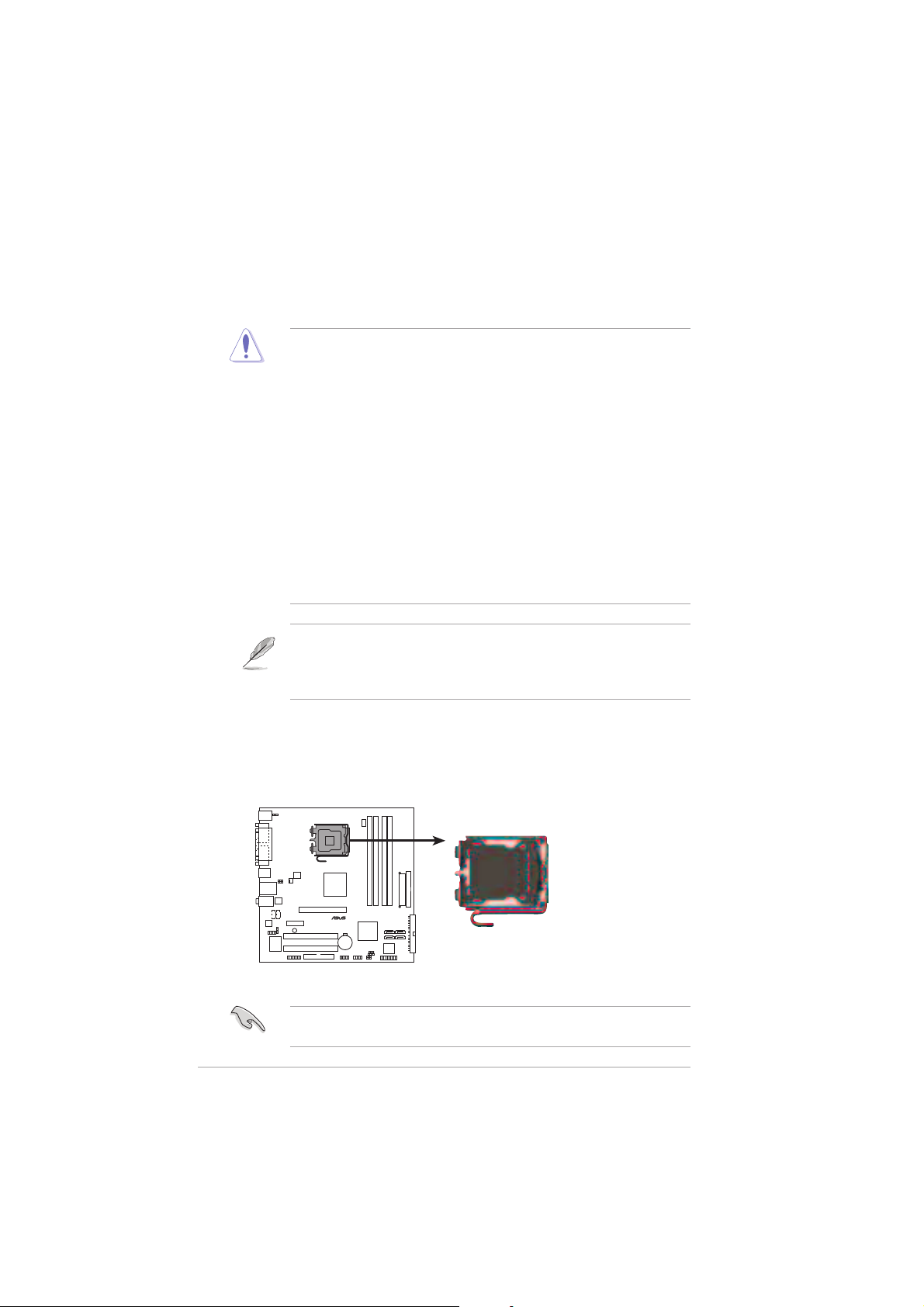
To install a CPU:
1. Locate the CPU socket on the motherboard.
P5VDC-MX
®
P5VDC-MX CPU Socket 775
Before installing the CPU, make sure that the socket box is facing
towards you and the load lever is on your left.
1-81-8
1-8
1-81-8
Chapter 1: Product introductionChapter 1: Product introduction
Chapter 1: Product introduction
Chapter 1: Product introductionChapter 1: Product introduction
Page 21
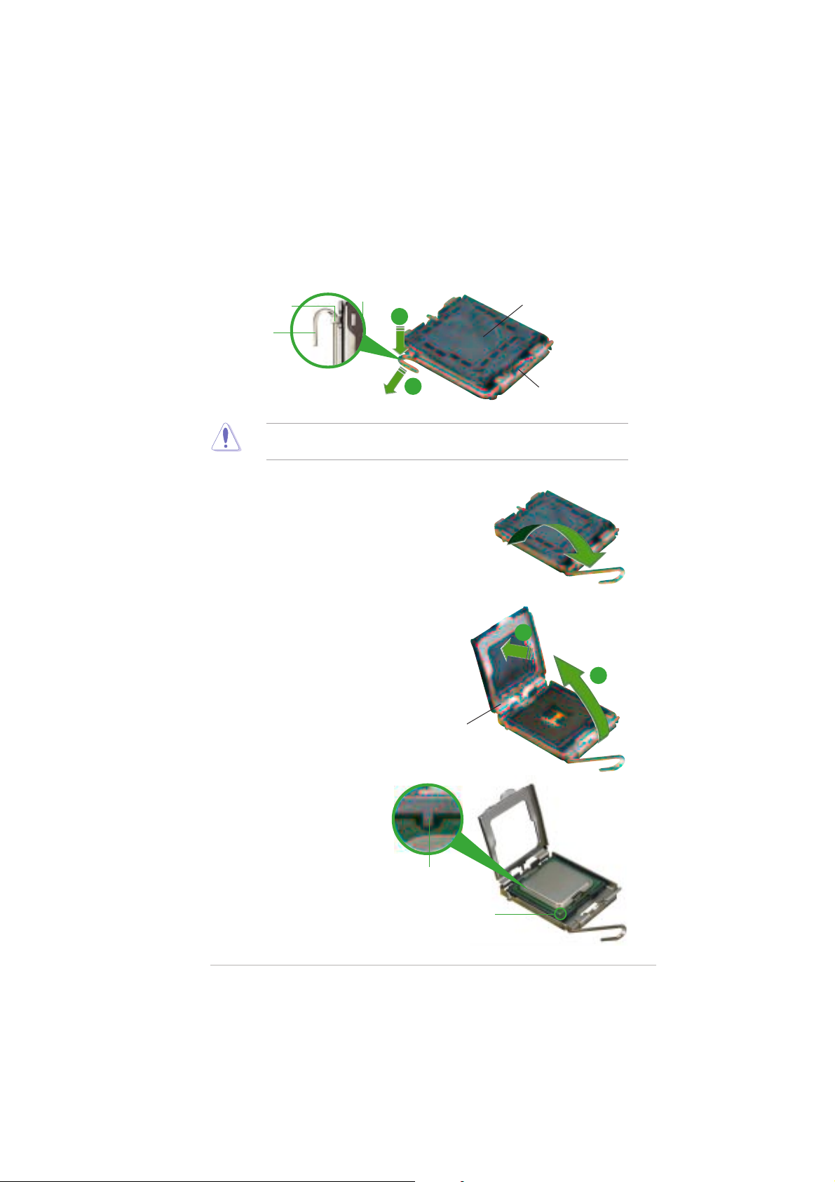
2. Press the load lever with your thumb (A) and move it to the left (B)
until it is released from the retention tab.
PnP CapPnP Cap
PnP Cap
Retention tabRetention tab
Retention tab
Retention tabRetention tab
Load leverLoad lever
Load lever
Load leverLoad lever
A
PnP CapPnP Cap
B
To prevent damage to the socket pins, do not remove the PnP cap
unless you are installing a CPU.
3. Lift the load lever in the direction
of the arrow to a 135º angle.
4. Lift the load plate with your
thumb and forefinger to a 100º
angle (A), then push the PnP cap
from the load plate window to
remove (B).
Load plateLoad plate
Load plate
Load plateLoad plate
This side of the camThis side of the cam
This side of the cam
This side of the camThis side of the cam
box should face you.box should face you.
box should face you.
box should face you.box should face you.
B
A
5. Position the CPU over the
socket, making sure that
the gold triangle is on
the bottom-left corner of
the socket. The socket
alignment key should fit
into the CPU notch.
ASUS P5VDC-MXASUS P5VDC-MX
ASUS P5VDC-MX
ASUS P5VDC-MXASUS P5VDC-MX
Alignment keyAlignment key
Alignment key
Alignment keyAlignment key
Gold triangle markGold triangle mark
Gold triangle mark
Gold triangle markGold triangle mark
1-91-9
1-9
1-91-9
Page 22
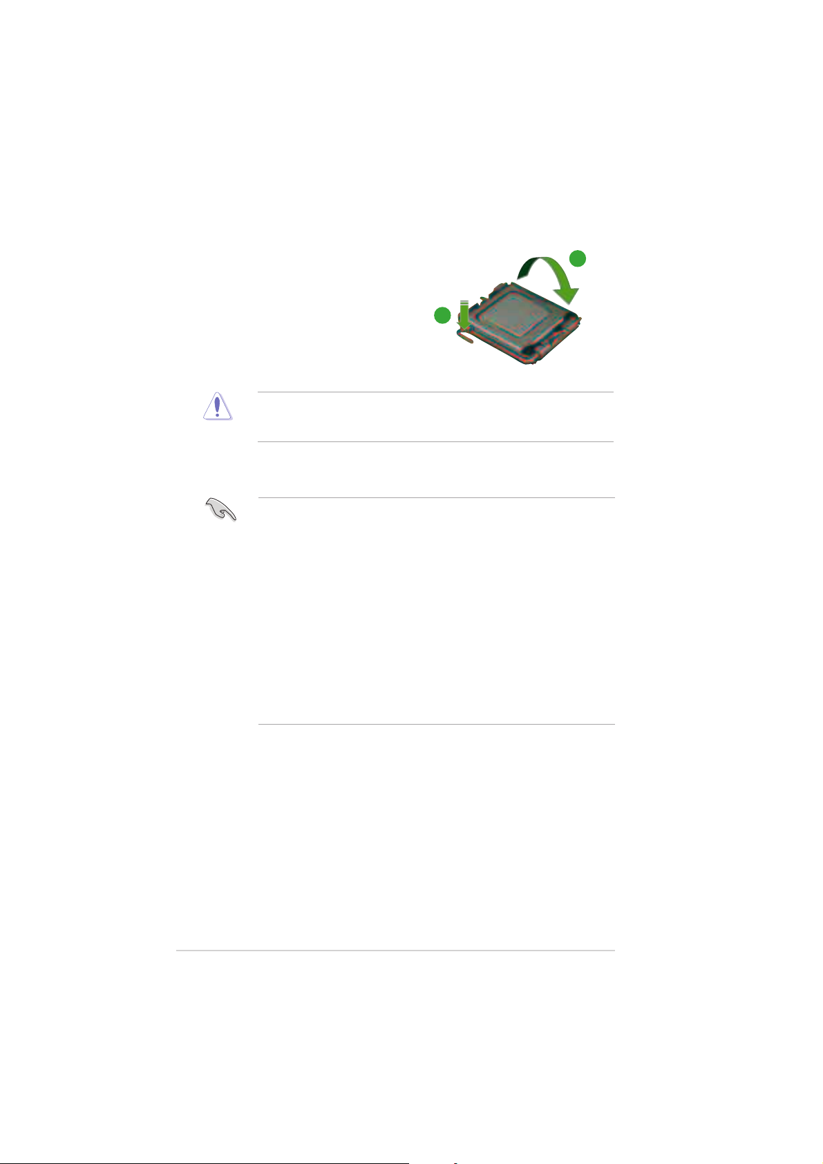
6. Close the load plate (A), then
push the load lever (B) until it
snaps into the retention tab.
The CPU fits in only one correct orientation. DO NOT force the CPU into
the socket to prevent bending the connectors on the socket and
damaging the CPU!
A
B
Notes on IntelNotes on Intel
Notes on Intel
Notes on IntelNotes on Intel
®
Hyper-Threading Technology Hyper-Threading Technology
Hyper-Threading Technology
Hyper-Threading Technology Hyper-Threading Technology
• This motherboard supports Intel® Pentium® 4 CPUs in the 775-land
package with Hyper-Threading Technology.
• Hyper-Threading Technology is supported under Windows® XP/2003
Server and Linux 1.7.x (kernel) and later versions only. Under Linux,
use the Hyper-Threading compiler to compile the code. If you are
using any other operating systems, disable the Hyper-Threading
Technology item in the BIOS to ensure system stability and
performance.
• Installing Windows® XP Service Pack 1 or later version is
recommended.
• Make sure to enable the Hyper-Threading Technology item in BIOS
before installing a supported operating system.
• For more information on Hyper-Threading Technology, visit
www.intel.com/info/hyperthreading.
To use the Hyper-Threading Technology on this motherboard:
®
1. Install an Intel
Pentium® 4 CPU in the 775-land package that supports
Hyper-Threading Technology.
2. Power up the system and enter the BIOS Setup (see Chapter 2: BIOS
setup). Under the Advanced Menu, make sure that the item
Hyper-Threading Technology is set to Enabled. The item appears only
if you installed a CPU that supports Hyper-Threading Technology.
3. Reboot the computer.
1-101-10
1-10
1-101-10
Chapter 1: Product introductionChapter 1: Product introduction
Chapter 1: Product introduction
Chapter 1: Product introductionChapter 1: Product introduction
Page 23

1.6.21.6.2
1.6.2
1.6.21.6.2
Installling the CPU heatsink and fanInstallling the CPU heatsink and fan
Installling the CPU heatsink and fan
Installling the CPU heatsink and fanInstallling the CPU heatsink and fan
The Intel® Pentium® 4/Pentium® D LGA775 processor requires a specially
designed heatsink and fan assembly to ensure optimum thermal condition
and performance.
• Install the motherboard to the chassis before you install the CPU fan
and heatsink assembly
• When you buy a boxed Intel® Pentium® 4 processor, the package
includes the CPU fan and heatsink assembly. If you buy a CPU
separately, make sure that you use only Intel®-certified
multi-directional heatsink and fan.
• Your Intel® Pentium® 4 LGA775 heatsink and fan assembly comes in
a push-pin design and requires no tool to install.
If you purchased a separate CPU heatsink and fan assembly, make sure
that a Thermal Interface Material is properly applied to the CPU heatsink
or CPU before you install the heatsink and fan assembly.
To install the CPU heatsink and fan:
1. Place the heatsink on top of the
installed CPU, making sure that
the four fasteners match the
holes on the motherboard.
Make sure each fastener is oriented as shown, with the narrow groove
directed outward.
ASUS P5VDC-MXASUS P5VDC-MX
ASUS P5VDC-MX
ASUS P5VDC-MXASUS P5VDC-MX
FastenerFastener
Fastener
FastenerFastener
Motherboard holeMotherboard hole
Motherboard hole
Motherboard holeMotherboard hole
1-111-11
1-11
1-111-11
Page 24
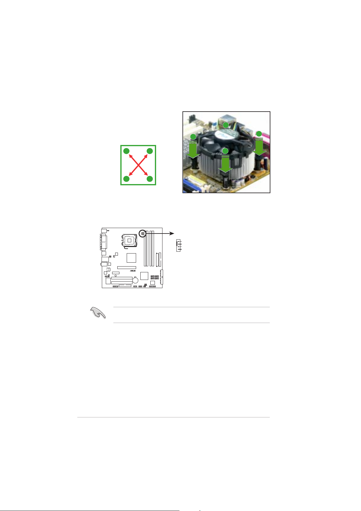
2. Push down two fasteners at a
time in a diagonal sequence to
secure the heatsink and fan
assembly in place.
B
A
A
A
B
B
A
B
3. When the fan and heatsink assembly is in place, connect the CPU fan
cable to the connector on the motherboard labeled CPU_FAN.
CPU_FAN
GND
CPU FAN PWR
CPU FAN IN
CPU FAN PWM
P5VDC-MX
®
P5VDC-MX CPU fan connector
Do not forget to connect the CPU fan connector! Hardware monitoring
errors can occur if you fail to plug this connector.
1-121-12
1-12
1-121-12
Chapter 1: Product introductionChapter 1: Product introduction
Chapter 1: Product introduction
Chapter 1: Product introductionChapter 1: Product introduction
Page 25

1.6.31.6.3
1.6.3
1.6.31.6.3
Uninstalling the CPU heatsink and fanUninstalling the CPU heatsink and fan
Uninstalling the CPU heatsink and fan
Uninstalling the CPU heatsink and fanUninstalling the CPU heatsink and fan
To uninstall the CPU heatsink and fan:
1. Disconnect the CPU fan
cable from the connector
on the motherboard labeled
CPU_FAN.
2. Rotate each fastener
counterclockwise.
3. Pull up two fasteners at a
time in a diagonal sequence
to disengage the heatsink
and fan assembly from the
A
motherboard.
A
B
B
A
B
B
ASUS P5VDC-MXASUS P5VDC-MX
ASUS P5VDC-MX
ASUS P5VDC-MXASUS P5VDC-MX
A
1-131-13
1-13
1-131-13
Page 26
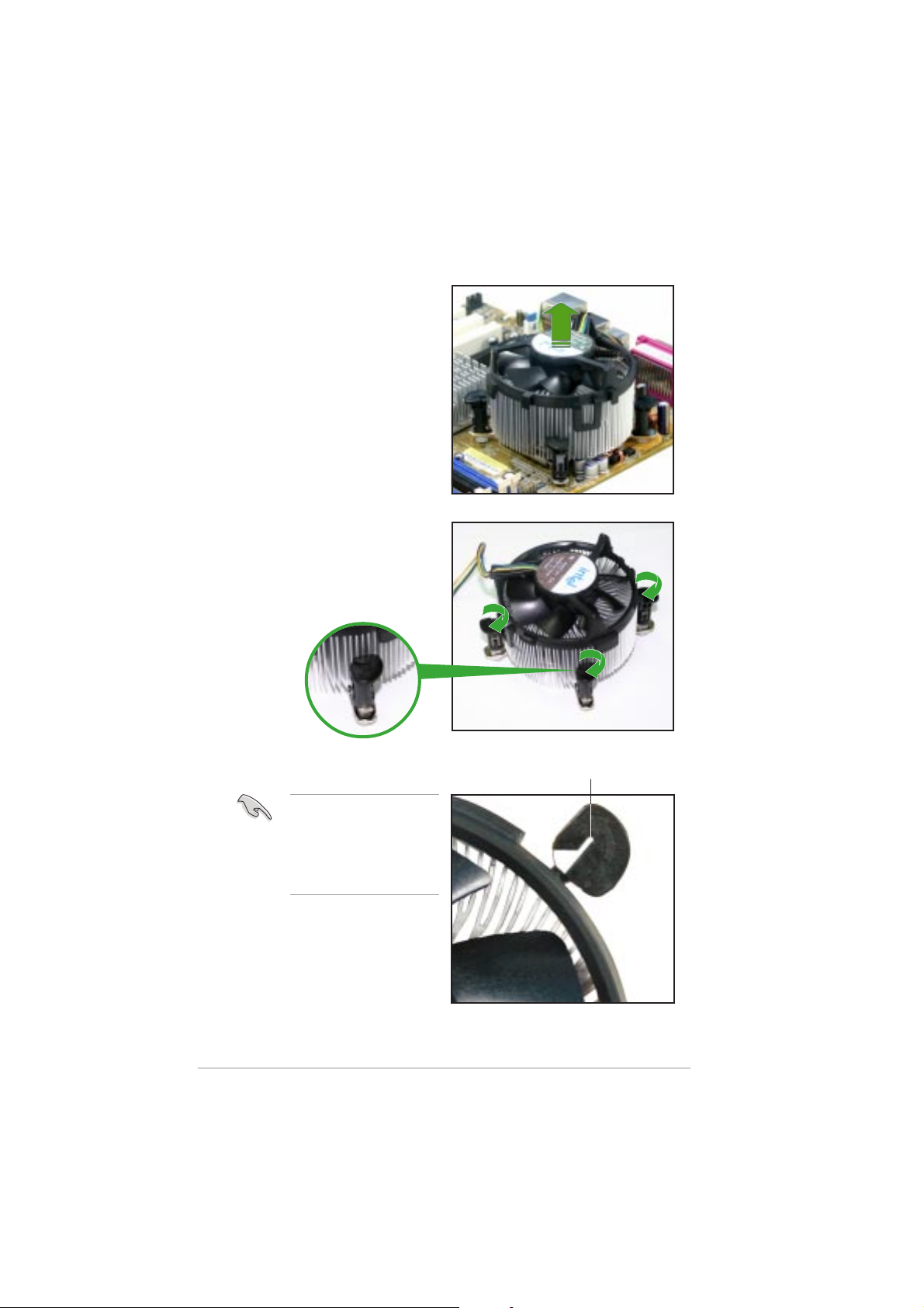
4. Remove the heatsink and fan
assembly from the
motherboard.
5. Rotate each fastener
clockwise to reset the
orientation.
1-141-14
1-14
1-141-14
The narrow end of the
groove should point
outward after resetting.
(The photo shows the
groove shaded for
emphasis.)
Narrow end of the grooveNarrow end of the groove
Narrow end of the groove
Narrow end of the grooveNarrow end of the groove
Chapter 1: Product introductionChapter 1: Product introduction
Chapter 1: Product introduction
Chapter 1: Product introductionChapter 1: Product introduction
Page 27
1.7 System memory
1.7.11.7.1
1.7.1
1.7.11.7.1
OverviewOverview
Overview
OverviewOverview
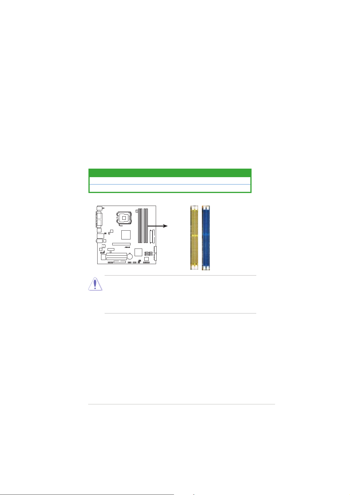
The motherboard comes with two 240-pin Double Data Rate (DDR2) and
two 184-pin DDR Dual Inline Memory Modules (DIMM) sockets.
DDR2 DIMMS are notched differently to prevent installation on a DDR DIMM
socket.
The following figure illustrates the location of the sockets:
ColorColor
Color
ColorColor
Blue DDR_1 and DDR_2
Yellow DDR2_1 and DDR2_2
P5VDC-MX
®
P5VDC-MX DDR DIMM sockets
• To prevent damage to the motherboard,
DDR2 memory simultaneously.DDR2 memory simultaneously.
DDR2 memory simultaneously.
DDR2 memory simultaneously.DDR2 memory simultaneously.
SocketsSockets
Sockets
SocketsSockets
DDR2_1
DDR2_2
DDR_1
DDR_2
do not use DDR anddo not use DDR and
do not use DDR and
do not use DDR anddo not use DDR and
• Due to chipset resource allocation, the system may detect less than
2 GB system memory when you installed two 1 GB DDR2 or DDR
memory modules.
1.7.21.7.2
1.7.2
1.7.21.7.2
Memory ConfigurationsMemory Configurations
Memory Configurations
Memory ConfigurationsMemory Configurations
You may install 256MB, 512MB, and 1 GB unbuffered non-ECC DDR/DDR2
DIMMs into the DIMM sockets.
ASUS P5VDC-MXASUS P5VDC-MX
ASUS P5VDC-MX
ASUS P5VDC-MXASUS P5VDC-MX
1-151-15
1-15
1-151-15
Page 28

1.7.31.7.3
1.7.3
1.7.31.7.3
DDR Qualified Vendors ListDDR Qualified Vendors List
DDR Qualified Vendors List
DDR Qualified Vendors ListDDR Qualified Vendors List
Visit the ASUS website (www.asus.com) for the latest DDR DIMM modules
for this motherboard.
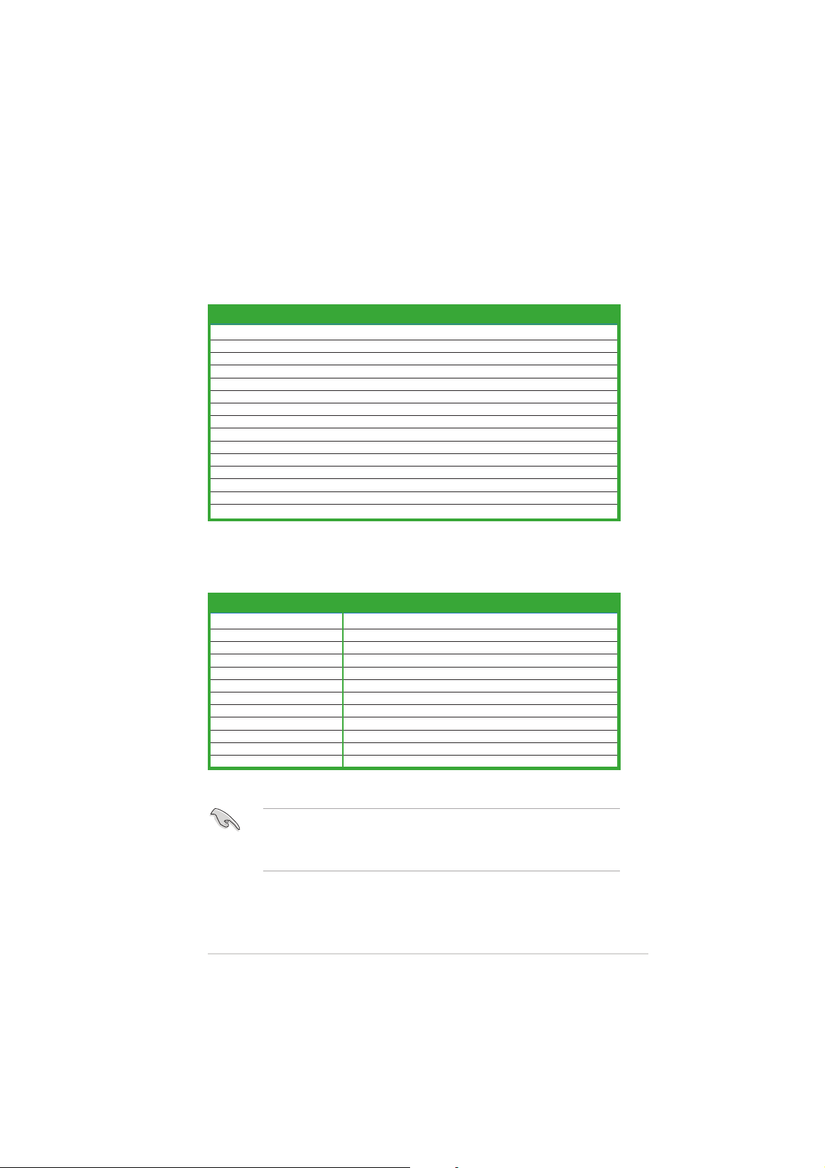
DDR2-533 Qualified Vendors ListDDR2-533 Qualified Vendors List
DDR2-533 Qualified Vendors List
DDR2-533 Qualified Vendors ListDDR2-533 Qualified Vendors List
DIMM support DIMM support
DIMM support
SizeSize
Vendor Vendor
Size
Vendor
SizeSize
Vendor Vendor
256MB KINGSTON E5116AB-5C-E N/A SS KVR533D2N4/256 V V
512MB KINGSTON HY5PS56821F-C4 N/A DS KVR533D2N4/512 V V
1024MB KINGSTON D6408TE7BL-37 N/A DS KVR533D2N4/1G V V
512MB SAMSUNG K4T51083QB-GCD5 N/A SS M378T6553BG0-CD5 V V
256MB SAMSUNG K4T56083QF-GCD5 N/A SS M378T3253FG0-CD5 V V
512MB SAMSUNG K4T56083QF-GCD5 N/A DS M378T6453FG0-CD5 V V
1024MB SAMSUNG K4T51083QB-GCD5 N/A DS M378T2953BG0-CD5 V V
512MB MICRON 4FBIID9BQM N/A DS MT16HTF6464AG-53EB2 V
256MB MICRON 4DBIIZ9BQT N/A SS N/A V V
256MB MICRON 4FBIID9CHM N/A SS MT8HTF3264AY-53EB3 V V
512MB MICRON 4FBIID9CHM N/A DS MT16HTF6464AY-53EB2 V V
512MB Infineon HYB18T512800AC37 N/A SS HYS64T64000GU-3.7-A V V
256MB Infineon HYB18T512160AF-3.7 N/A SS HYS64T32000HU-3.7-A V V
512MB Infineon HYB18T512800AF37 N/A SS HYS64T64000HU-3.7-A V V
256MB Infineon HYB18T512800AF37 N/A DS HYS64T128020HU-3.7-A V V
256MB Infineon HYB18T5121608BF-3.7 N/A SS HYS64T32000HU-3.7-B V V
512MB Infineon HYB18T512800BF37 N/A SS HYS64T64000HU-3.7-B V V
1024MB Infineon HYB18T512800BF37 N/A DS HYS64T128020HU-3.7-B V V
512MB Hynix HY5PS12821F-C4 N/A SS HYMP564U648-C4 V V
1024MB Hynix HY5PS12821F-C4 N/A DS HYMP512U648-C4 V V
1024MB Hynix HY5PS12821FP-C4 N/A DS HYMP512U648-C4 V V
512MB Hynix HY5PS12821AFP-C3 N/A SS HYMP564U64AP8-C3 V V
1024MB Hynix HY5PS12821AFP-C3 N/A DS HYMP512U64AP8-C3 V V
512MB ELPIDA E5108AB-5C-E N/A SS EBE51UD8ABFA-5C V V
512MB ELPIDA E5108AB-5C-E N/A SS EBE51UD8ABFA-5C-E V V
1024MB ELPIDA E5108AB-5C-E N/A DS EBE11UD8ABFA-5C-E V V
2048MB ELPIDA E1108AA-5C-E N/A DS EBE21EE8AAFA-5C-E V
256MB CORSAIR MIII0051832M8CEC N/A SS VS256MB533D2 V V
512MB CORSAIR MI110052432M8CEC N/A DS VS512MB533D2 V V
256MB Apacer E5116AB-5C-E N/A SS 78.81077.420 V V
256MB crucial Heat-Sink Package N/A SS BL3264AA53V.8FB V V
512MB crucial Heat-Sink Package N/A DS BL6464AA53V.16FB V V
256MB KINGMAX K4T56083QF-GCD5 N/A SS KLBB68K-38SP4 V V
1024MB KINGMAX E5108AB-5C-E N/A DS KLBD48F-A8EP4 V V
512MB KINGMAX E5108AB-5C-E N/A SS KLBC28F-A8EP4 V
512MB KINGMAX KKEA88A4IA-37 N/A SS KLBC28F-A8KP4 V V
256MB KINGMAX E5116AB-5C-E N/A SS KLBB68F-36EP4 V V
512MB KINGMAX E5108AE-5C-E N/A SS KLBC28F-A8EB4 V V
512MB Transcend K4T51083QB-GCD5 N/A SS TS64MLQ64V5J V
1024MB Transcend K4T51083QB-GCD5 N/A DS TS128MLQ64V5J V V
Model Model
Model
Model Model
Brand Side(s) ComponentBrand Side(s) Component
Brand Side(s) Component
Brand Side(s) ComponentBrand Side(s) Component
DIMM support DIMM support
AA
BB
A
B
AA
BB
Legend:Legend:
Legend:
Legend:Legend:
A A
A - supports one module inserted in any
A A
BB
B - supports one pair of modules inserted into both of the
BB
SSSS
S S - Single-sided
SSSS
DSDS
D S - Double-sided
DSDS
1-161-16
1-16
1-161-16
yellowyellow
yellow slot.
yellowyellow
yellowyellow
yellow slots.
yellowyellow
Chapter 1: Product introductionChapter 1: Product introduction
Chapter 1: Product introduction
Chapter 1: Product introductionChapter 1: Product introduction
Page 29

DDR400 Qualified Vendors ListDDR400 Qualified Vendors List
DDR400 Qualified Vendors List
DDR400 Qualified Vendors ListDDR400 Qualified Vendors List
DIMM support DIMM support
DIMM support
SizeSize
Size
SizeSize
512MB KINGSTON Heat-Sink Package N/A DS KHX3200A/512 V V
256MB KINGSTON D3208DL3T-5A N/A SS KVR400X64C3A/256 V V
256MB KINGSTON A2S56D30BTP N/A SS KVR400X64C3A/256 V
512MB KINGSTON V58C2256804SAT5 N/A DS KVR400X64C3A/512 V V
512MB KINGSTON HY5DU12822BT-D43 N/A SS KVR400X64C3A/512 V V
1024MB KINGSTON HYB25D512800BE-5B N/A DS KVR400X64C3A/1G V V
256MB SAMSUNG K4H560838E-TCCC SAMSUNG SS M368L3223ETM-CCC V V
256MB SAMSUNG K4H560838F-TCCC SAMSUNG SS M368L3223FTN-CCC V
512MB SAMSUNG K4H560838F-TCCC SAMSUNG DS M368L6423FTN-CCC V V
512MB SAMSUNG K4H510838B-TCCC SAMSUNG SS M368L6523BTM-CCC V V
256MB MICRON MT46V32M8TG-5BC MICRON SS MT8VDDT3264AG-40BCB V
512MB MICRON MT46V32M8TG-5BC MICRON DS MT16VDDT6464AG-40BCB V V
256MB Infineon HYB25D256800CE-5C Infineon SS HYS64D32300HU-5-C V V
512MB Infineon HYB25D256800CE-5C Infineon DS HYS64D64320HU-5-C V V
256MB Infineon HYB25D512160CE-5C Infineon SS HYS64D32301HU-5-C V V
512MB Infineon HYB25D512800CE-5C Infineon SS HYS64D64300HU-5-C V
1024MB Infineon HYB25D512800CE-5B Infineon DS HYS64D128320HU-5-C V V
256MB CORSAIR W942508BH-5 N/A SS CMX256A-3200C2PT V V
512MB CORSAIR Heat-Sink Package N/A DS CMX512-3200C2 V V
512MB CORSAIR VS32M8-5 N/A DS VS512MB400 V V
512MB CORSAIR Heat-Sink Package N/A DS CMXP512-3200XL V
1024MB CORSAIR Heat-Sink Package N/A DS TWINX2048-3200C2 V V
256MB Hynix HY5DU56822DT-D43 N/A SS HYMD232646D8J-D43 V V
512MB Hynix HY5DU56822DT-D43 N/A DS HYMD264646D8J-D43 V
256MB Transcend K4H560838F-TCCC SAMSUNG SS TS32MLD64V4F3 V V
512MB Transcend K4H560838F-TCCC SAMSUNG DS TS64MLD64V4F3 V
1024MB Transcend K4H510838B-TCCC SAMSUNG DS TS128MLD64V4J V V
256MB A DATA K4H560838E-TCCC SAMSUNG SS MDOSS6F3G31Y0K1E0Z V V
512MB A DATA K4H560838F-TCCC SAMSUNG DS MDOSS6F3H41Y0N1E0Z V V
256MB A DATA HY5DU56822CT-D43 Hynix SS MDOHY6F3G31Y0N1E0Z V V
512MB A DATA HY5DU56822CT-D43 Hynix DS MDOHY6F3H41Y0N1E0Z V V
256MB A DATA ADD8608A8A-5B N/A SS MDOAD5F3G31Y0D1E02 V
512MB A DATA ADD8608A8A-5B N/A DS MDOAD5F3H41Y0D1E02 V
256MB KINGMAX KDL388P4LA-50 N/A SS MPXB62D-38KT3R V V
256MB crucial Heat-Sink Package Ballistix SS BL3264Z402.8TG V V
VendorVendor
Vendor
VendorVendor
ModelModel
Model
ModelModel
BrandBrand
Brand
BrandBrand
Side(s)Side(s)
Side(s)
Side(s)Side(s)
DIMM support DIMM support
ComponentComponent
Component
ComponentComponent
AA
BB
A
B
AA
BB
Legend:Legend:
Legend:
Legend:Legend:
A A
A - supports one module inserted in any
A A
BB
B - supports one pair of modules inserted into both of the
BB
SSSS
S S - Single-sided
SSSS
DSDS
D S - Double-sided
DSDS
ASUS P5VDC-MXASUS P5VDC-MX
ASUS P5VDC-MX
ASUS P5VDC-MXASUS P5VDC-MX
blueblue
blue slot.
blueblue
blueblue
blue slots.
blueblue
1-171-17
1-17
1-171-17
Page 30
1.7.41.7.4
1.7.4
1.7.41.7.4
Installing a DDR DIMM(blue slots)Installing a DDR DIMM(blue slots)
Installing a DDR DIMM(blue slots)
Installing a DDR DIMM(blue slots)Installing a DDR DIMM(blue slots)
Make sure to unplug the power supply before adding or removing DIMMs
or other system components. Failure to do so may cause severe damage
to both the motherboard and the components.
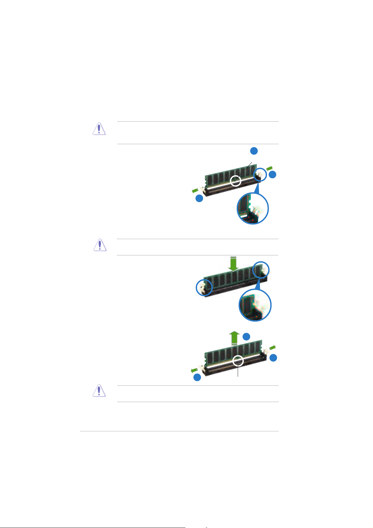
1. Unlock a DIMM socket by
pressing the retaining clips
outward.
2. Align a DIMM on the socket such
that the notch on the DIMM
matches the break on the
socket.
A DDR DIMM is keyed with a notch so that it fits in only one direction.
DO NOT force a DIMM into a socket to avoid damaging the DIMM.
3. Firmly insert the DIMM into the
socket until the retaining clips
snap back in place and the DIMM
is properly seated.
2
DDR DIMM notchDDR DIMM notch
DDR DIMM notch
DDR DIMM notchDDR DIMM notch
1
1
Unlocked retaining clipUnlocked retaining clip
Unlocked retaining clip
Unlocked retaining clipUnlocked retaining clip
1.7.51.7.5
1.7.5
1.7.51.7.5
Removing a DDR DIMMRemoving a DDR DIMM
Removing a DDR DIMM
Removing a DDR DIMMRemoving a DDR DIMM
Follow these steps to remove a DIMM.
1. Simultaneously press the
retaining clips outward to unlock
the DIMM.
Support the DIMM lightly with your fingers when pressing the retaining
clips. The DIMM might get damaged when it flips out with extra force.
2. Remove the DIMM from the socket.
1-181-18
1-18
1-181-18
Locked Retaining ClipLocked Retaining Clip
Locked Retaining Clip
Locked Retaining ClipLocked Retaining Clip
2
1
1
Chapter 1: Product introductionChapter 1: Product introduction
Chapter 1: Product introduction
Chapter 1: Product introductionChapter 1: Product introduction
DDR DIMM notchDDR DIMM notch
DDR DIMM notch
DDR DIMM notchDDR DIMM notch
Page 31

1.7.61.7.6
1.7.6
1.7.61.7.6
Installing a DDR2 DIMM(yellow slots)Installing a DDR2 DIMM(yellow slots)
Installing a DDR2 DIMM(yellow slots)
Installing a DDR2 DIMM(yellow slots)Installing a DDR2 DIMM(yellow slots)
Unplug the power supply before adding or removing DIMMs or other
system components. Failure to do so can cause severe damage to both
the motherboard and the components.
To install a DIMM:
1. Unlock a DIMM socket by
pressing the retaining
clips outward.
2. Align a DIMM on the
socket such that the
notch on the DIMM
matches the break on the
1
socket.
3. Firmly insert the DIMM
into the socket until the
retaining clips snap back
in place and the DIMM is
properly seated.
• A DDR2 DIMM is keyed with a notch so that it fits in only one
direction. Do not force a DIMM into a socket to avoid damaging the
DIMM.
• The DDR2 DIMM sockets do not support DDR DIMMs. Do not install
DDR DIMMs to the DDR2 DIMM sockets.
1.7.71.7.7
1.7.7
1.7.71.7.7
Removing a DDR2 DIMMRemoving a DDR2 DIMM
Removing a DDR2 DIMM
Removing a DDR2 DIMMRemoving a DDR2 DIMM
Follow these steps to remove a DIMM.
1. Simultaneously press the retaining
clips outward to unlock the DIMM.
2
DDR2 DIMMDDR2 DIMM
DDR2 DIMM
DDR2 DIMMDDR2 DIMM
3
Unlocked retainingUnlocked retaining
Unlocked retaining
Unlocked retainingUnlocked retaining
2
Support the DIMM lightly
with your fingers when
pressing the retaining
clips. The DIMM might get
damaged when it flips out
with extra force.
2. Remove the DIMM from the socket.
ASUS P5VDC-MXASUS P5VDC-MX
ASUS P5VDC-MX
ASUS P5VDC-MXASUS P5VDC-MX
1
DDR2 DIMM notchDDR2 DIMM notch
DDR2 DIMM notch
1
DDR2 DIMM notchDDR2 DIMM notch
1-191-19
1-19
1-191-19
Page 32

1.8 Expansion slots
In the future, you may need to install expansion cards. The following
sub-sections describe the slots and the expansion cards that they support.
Make sure to unplug the power cord before adding or removing
expansion cards. Failure to do so may cause you physical injury and
damage motherboard components.
1.8.11.8.1
1.8.1
1.8.11.8.1
To install an expansion card:
1. Before installing the expansion card, read the documentation that
2. Remove the system unit cover (if your motherboard is already
3. Remove the bracket opposite the slot that you intend to use. Keep
4. Align the card connector with the slot and press firmly until the card is
5. Secure the card to the chassis with the screw you removed earlier.
6. Replace the system cover.
1.8.21.8.2
1.8.2
1.8.21.8.2
After installing the expansion card, configure it by adjusting the software
settings.
1. Turn on the system and change the necessary BIOS settings, if any.
2. Assign an IRQ to the card. Refer to the tables on the next page.
3. Install the software drivers for the expansion card.
Installing an expansion cardInstalling an expansion card
Installing an expansion card
Installing an expansion cardInstalling an expansion card
came with it and make the necessary hardware settings for the card.
installed in a chassis).
the screw for later use.
completely seated on the slot.
Configuring an expansion cardConfiguring an expansion card
Configuring an expansion card
Configuring an expansion cardConfiguring an expansion card
See Chapter 2 for information on BIOS setup.
1-201-20
1-20
1-201-20
Chapter 1: Product introductionChapter 1: Product introduction
Chapter 1: Product introduction
Chapter 1: Product introductionChapter 1: Product introduction
Page 33
1.8.31.8.3
1.8.3
1.8.31.8.3
Standard interrupt assignmentsStandard interrupt assignments
Standard interrupt assignments
Standard interrupt assignmentsStandard interrupt assignments
Interrupt assignmentsInterrupt assignments
Interrupt assignments
Interrupt assignmentsInterrupt assignments
IRQIRQ
IRQ
IRQIRQ
0 1 System Timer
1 2 Keyboard Controller
2 • Re-direct to IRQ#9
4 12 Communications Port (COM)*
5 13 IRQ holder for PCI steering*
6 14 Floppy Disk Controller
7 15 Printer Port (LPT1)*
8 3 System CMOS/Real Time Clock
9 4 IRQ holder for PCI steering*
10 5 IRQ holder for PCI steering*
11 6 PCI-E x1
12 7 PS/2 Compatible Mouse Port*
13 8 Numeric Data Processor
14 9 Primary IDE Channel
15 10 Secondary IDE Channel
PriorityPriority
Priority
PriorityPriority
Standard FunctionStandard Function
Standard Function
Standard FunctionStandard Function
* These IRQs are usually available for ISA or PCI devices.
IRQ assignments for this motherboardIRQ assignments for this motherboard
IRQ assignments for this motherboard
IRQ assignments for this motherboardIRQ assignments for this motherboard
AA
A
AA
PCI slot 1 — shared — —
PCI slot 2 — — shared —
PCIe x1 slot* Fixed Fixed Fixed Fixed
AGP 8X slot shared — — —
Onboard USB controller 1 shared — — —
Onboard USB controller 2 — — shared —
Onboard USB controller 3 — shared — —
Onboard USB controller 4 — — — shared
Onboard USB 2.0 controller — — shared —
Onboard LAN shared — — —
Onboard audio — shared — —
Onboard VGA shared — — —
BB
B
BB
CC
C
CC
DD
D
DD
* The PCIe x1 slot does not need IRQ assignment.
When using PCI cards on shared slots, ensure that the drivers support
“Share IRQ” or that the cards do not need IRQ assignments. Otherwise,
conflicts will arise between the two PCI groups, making the system
unstable and the card inoperable.
ASUS P5VDC-MXASUS P5VDC-MX
ASUS P5VDC-MX
ASUS P5VDC-MXASUS P5VDC-MX
1-211-21
1-21
1-211-21
Page 34

1.8.41.8.4
1.8.4
1.8.41.8.4
The PCI slots support cards such as a
LAN card, SCSI card, USB card, and
other cards that comply with PCI
specifications. The figure shows a
LAN card installed on a PCI slot.
PCI slotsPCI slots
PCI slots
PCI slotsPCI slots
1.8.51.8.5
1.8.5
1.8.51.8.5
This motherboard supports PCI
Express x1 network cards, SCSI cards
and other cards that comply with the
PCI Express specifications. The figure
shows a network card installed on the
PCI Express x1 slot.
1.8.61.8.6
1.8.6
1.8.61.8.6
The Accelerated Graphics Port (AGP) slot supports AGP8X/4X cards. When
you buy an AGP card, make sure that you ask for one with +1.5V
specification. Note the notches on the card golden fingers to ensure that
they fit the AGP slot on your motherboard.
PCI Express x1 slotPCI Express x1 slot
PCI Express x1 slot
PCI Express x1 slotPCI Express x1 slot
AGP slotAGP slot
AGP slot
AGP slotAGP slot
Install only 1.5 V or 0.8 V AGP cards on this motherboard! 3.3V AGP
cards are not supported in this motherboard.
P5VDC-MX
®
Keyed for 1.5v
1-221-22
1-22
1-221-22
P5VDC-MX Accelerated Graphics Port (AGP)
Chapter 1: Product introductionChapter 1: Product introduction
Chapter 1: Product introduction
Chapter 1: Product introductionChapter 1: Product introduction
Page 35

1.9 Jumpers
1.1.
Clear RTC RAM (CLRTC)Clear RTC RAM (CLRTC)
1.
Clear RTC RAM (CLRTC)
1.1.
Clear RTC RAM (CLRTC)Clear RTC RAM (CLRTC)
This jumper allows you to clear the Real Time Clock (RTC) RAM in
CMOS. You can clear the CMOS memory of date, time, and system
setup parameters by erasing the CMOS RTC RAM data. The onboard
button cell battery powers the RAM data in CMOS, which include
system setup information such as system passwords.
To erase the RTC RAM:
1.Turn OFF the computer and unplug the power cord.
2.Remove the onboard battery.
3.Move the jumper cap from pins 1-2 (default) to pins 2-3. Keep the
cap on pins 2-3 for about 5~10 seconds, then move the cap back
to pins 1-2.
4.Re-install the battery.
5.Plug the power cord and turn ON the computer.
6.Hold down the <Del> key during the boot process and enter BIOS
setup to re-enter data.
Except when clearing the RTC RAM, never remove the cap on CLRTC
jumper default position. Removing the cap will cause system boot failure!
P5VDC-MX Clear RTC RAM
You do not need to clear the RTC when the system hangs due to
overclocking. For system failure due to overclocking, use the C.P.R. (CPU
Parameter Recall) feature. Shut down and reboot the system so the BIOS
can automatically reset parameter settings to default values.
ASUS P5VDC-MXASUS P5VDC-MX
ASUS P5VDC-MX
ASUS P5VDC-MXASUS P5VDC-MX
P5VDC-MX
®
CLRTC
12 23
Normal CLEAR
(Default)
1-231-23
1-23
1-231-23
Page 36

2.2.
Keyboard power (3-pin KBPWR)Keyboard power (3-pin KBPWR)
2.
Keyboard power (3-pin KBPWR)
2.2.
Keyboard power (3-pin KBPWR)Keyboard power (3-pin KBPWR)
This jumper allows you to enable or disable the keyboard wake-up
feature. Set this jumper to pins 2-3 (+5VSB) to wake up the
computer when you press a key on the keyboard (the default is the
Space Bar). This feature requires an ATX power supply that can supply
at least 1A on the +5VSB lead, and a corresponding setting in the
BIOS.
KBPWR
2312
+5V +5VSB
(Default)
P5VDC-MX
®
P5VDC-MX Keyboard power setting
3.3.
USB device wake-up (3-pin USBPW12, USBPW34,USB device wake-up (3-pin USBPW12, USBPW34,
3.
USB device wake-up (3-pin USBPW12, USBPW34,
3.3.
USB device wake-up (3-pin USBPW12, USBPW34,USB device wake-up (3-pin USBPW12, USBPW34,
USBPW56, USBPW78)USBPW56, USBPW78)
USBPW56, USBPW78)
USBPW56, USBPW78)USBPW56, USBPW78)
Set these jumpers to +5V to wake up the computer from S1 sleep
mode (CPU stopped, DRAM refreshed, system running in low power
mode) using the connected USB devices. Set to +5VSB to wake up
from S3 and S4 sleep modes (no power to CPU, DRAM in slow refresh,
power supply in reduced power mode).
The USBPWR12 and USBPWR34 jumpers are for the rear USB ports.
The USBPWR56 and USBPWR78 jumpers are for the internal USB
connectors that you can connect to additional USB ports.
USBPW12
USBPW34
21
2
3
1-241-24
1-24
1-241-24
P5VDC-MX
®
P5VDC-MX USB device wake-up
+5V
(Default)
USBPW56
USBPW78
21
+5V
(Default)
+5VSB
2
+5VSB
3
• The USB device wake-up feature requires a power supply that can
provide 500mA on the +5VSB lead for each USB port; otherwise,
the system would not power up.
• The total current consumed must NOT exceed the power supply
capability (+5VSB) whether under normal condition or in sleep mode.
Chapter 1: Product introductionChapter 1: Product introduction
Chapter 1: Product introduction
Chapter 1: Product introductionChapter 1: Product introduction
Page 37

1.10 Connectors
1.10.11.10.1
1.10.1
1.10.11.10.1
1.1.
1.
1.1.
2.2.
2.
2.2.
Rear panel connectorsRear panel connectors
Rear panel connectors
Rear panel connectorsRear panel connectors
1
11
PS/2 mouse port (green).PS/2 mouse port (green).
PS/2 mouse port (green). This port is for a PS/2 mouse.
PS/2 mouse port (green).PS/2 mouse port (green).
Parallel port.Parallel port.
Parallel port. This 25-pin port connects a parallel printer, a scanner,
Parallel port.Parallel port.
10
2 3
9
8
7
or other devices.
3.3.
LAN (RJ-45) port.LAN (RJ-45) port.
3.
LAN (RJ-45) port. This port allows connection to a Local Area
3.3.
LAN (RJ-45) port.LAN (RJ-45) port.
Network (LAN) through a network hub.
LAN port LED indicationsLAN port LED indications
LAN port LED indications
LAN port LED indicationsLAN port LED indications
ACT/LINK LED ACT/LINK LED
ACT/LINK LED
ACT/LINK LED ACT/LINK LED
StatusStatus
Status
StatusStatus
OFF No link OFF No link
ORANGE 100 Linked GREEN 10 Linked
BLINKING Data activity BLINKING Data activity
DescriptionDescription
Description
DescriptionDescription
SPEED LED SPEED LED
SPEED LED
SPEED LED SPEED LED
StatusStatus
Status
StatusStatus
DescriptionDescription
Description
DescriptionDescription
ACT/LINK
LED
LAN port
4
5
6
SPEED
LED
4.4.
Line In port (light blue).Line In port (light blue).
4.
Line In port (light blue). This port connects a tape, CD, DVD
4.4.
Line In port (light blue).Line In port (light blue).
player, or other audio sources. In 4-channel and 6-channel
configuration, the function of this port becomes Rear Speaker Out.
5.5.
Line Out port (lime).Line Out port (lime).
5.
Line Out port (lime). This port connects a headphone or a
5.5.
Line Out port (lime).Line Out port (lime).
speaker. In 4-channel and 6-channel configuration, the function of this
port becomes Front Speaker Out.
6.6.
Microphone port (pink). Microphone port (pink).
6.
Microphone port (pink). This port connects a microphone. In a
6.6.
Microphone port (pink). Microphone port (pink).
6-channel configuration, the function of this port becomes Bass/
Center Speaker.
ASUS P5VDC-MXASUS P5VDC-MX
ASUS P5VDC-MX
ASUS P5VDC-MXASUS P5VDC-MX
1-251-25
1-25
1-251-25
Page 38
Refer to the audio configuration table for the function of the audio ports
in 2, 4, or 6-channel configuration.
Audio 2, 4, or 6-channel configurationAudio 2, 4, or 6-channel configuration
Audio 2, 4, or 6-channel configuration
Audio 2, 4, or 6-channel configurationAudio 2, 4, or 6-channel configuration
PortPort
Port
PortPort
Light Blue Line In Rear Speaker Out Rear Speaker Out
Lime Line Out Front Speaker Out Front Speaker Out
Pink Mic In Mic In Bass/Center
7.7.
USB 2.0 ports 3 and 4.USB 2.0 ports 3 and 4.
7.
USB 2.0 ports 3 and 4. These two 4-pin Universal Serial Bus
7.7.
USB 2.0 ports 3 and 4.USB 2.0 ports 3 and 4.
HeadsetHeadset
Headset
HeadsetHeadset
2-channel2-channel
2-channel
2-channel2-channel
4-channel4-channel
4-channel
4-channel4-channel
6-channel6-channel
6-channel
6-channel6-channel
(USB) ports are available for connecting USB 2.0 devices.
8.8.
USB 2.0 ports 1 and 2.USB 2.0 ports 1 and 2.
8.
USB 2.0 ports 1 and 2. These two 4-pin Universal Serial Bus
8.8.
USB 2.0 ports 1 and 2.USB 2.0 ports 1 and 2.
(USB) ports are available for connecting USB 2.0 devices.
9.9.
VGA port.VGA port.
9.
VGA port. This 15-pin VGA port connects to a VGA monitor.
9.9.
VGA port.VGA port.
10.10.
Serial connector. Serial connector.
10.
Serial connector. This 9-pin COM port is for serial devices.
10.10.
Serial connector. Serial connector.
11.11.
PS/2 keyboard port (purple).PS/2 keyboard port (purple).
11.
PS/2 keyboard port (purple). This port is for a PS/2 keyboard.
11.11.
PS/2 keyboard port (purple).PS/2 keyboard port (purple).
1-261-26
1-26
1-261-26
1.10.21.10.2
1.10.2
1.10.21.10.2
1.1.
1.
1.1.
Internal connectorsInternal connectors
Internal connectors
Internal connectorsInternal connectors
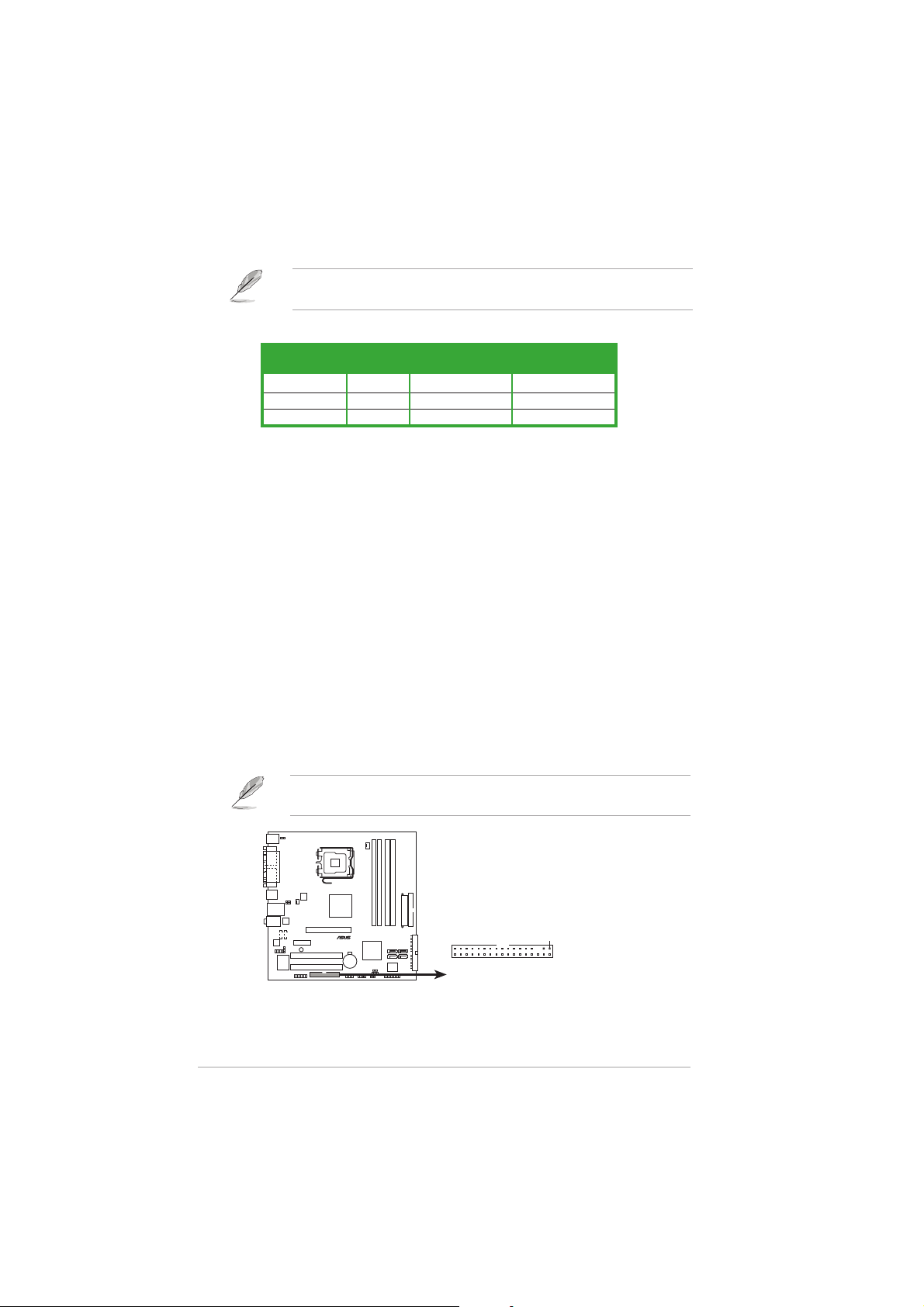
Floppy disk drive connector (34-1 pin FLOPPY)Floppy disk drive connector (34-1 pin FLOPPY)
Floppy disk drive connector (34-1 pin FLOPPY)
Floppy disk drive connector (34-1 pin FLOPPY)Floppy disk drive connector (34-1 pin FLOPPY)
This connector is for the provided floppy disk drive (FDD) signal cable.
Insert one end of the cable to this connector, then connect the other
end to the signal connector at the back of the floppy disk drive.
Pin 5 on the connector is removed to prevent incorrect cable connection
when using an FDD cable with a covered Pin 5.
P5VDC-MX
®
P5VDC-MX Floppy disk drive connector
FLOPPY
NOTE: Orient the red markings on
the floppy ribbon cable to PIN 1.
Chapter 1: Product introductionChapter 1: Product introduction
Chapter 1: Product introduction
Chapter 1: Product introductionChapter 1: Product introduction
PIN 1
Page 39

2.2.
Primary/Secondary IDE connector (40-1 pin PRI_IDE,Primary/Secondary IDE connector (40-1 pin PRI_IDE,
2.
Primary/Secondary IDE connector (40-1 pin PRI_IDE,
2.2.
Primary/Secondary IDE connector (40-1 pin PRI_IDE,Primary/Secondary IDE connector (40-1 pin PRI_IDE,
SEC_IDE)SEC_IDE)
SEC_IDE)
SEC_IDE)SEC_IDE)
These connectors are for Ultra DMA 133/100/66 signal cables. The
Ultra DMA 133/100/66 signal cable has three connectors: a blue
connector for the primary IDE connector on the motherboard, a black
connector for an Ultra DMA 100/66 IDE slave device (optical drive/
hard disk drive), and a gray connector for an Ultra DMA 100/66 IDE
master device (hard disk drive). If you install two hard disk drives, you
must configure the second drive as a slave device by setting its
jumper accordingly. Refer to the hard disk documentation for the
jumper settings.
1. Follow the hard disk drive documentation when setting the device in
master or slave mode.
2. Pin 20 on each IDE connector is removed to match the covered hole
on the UltraATA cable connector. This prevents incorrect orientation
when you connect the cables.
3. The hole near the blue connector on the UltraATA cable is
intentional.
NOTE: Orient the red markings
(usually zigzag) on the IDE
PIN 1
ribbon cable to PIN 1.
P5VDC-MX IDE connectors
ASUS P5VDC-MXASUS P5VDC-MX
ASUS P5VDC-MX
ASUS P5VDC-MXASUS P5VDC-MX
P5VDC-MX
®
PRI_IDE
PIN 1
SEC_IDE
1-271-27
1-27
1-271-27
Page 40

3.3.
Serial ATA connectors (7-pin SATA1, SATA2, SATA3,Serial ATA connectors (7-pin SATA1, SATA2, SATA3,
3.
Serial ATA connectors (7-pin SATA1, SATA2, SATA3,
3.3.
Serial ATA connectors (7-pin SATA1, SATA2, SATA3,Serial ATA connectors (7-pin SATA1, SATA2, SATA3,
SATA4)SATA4)
SATA4)
SATA4)SATA4)
These connectors are for the Serial ATA signal cables for Serial ATA
hard disk drives.
If you installed Serial ATA hard disk drives, you can can create a RAID
0, RAID 1, RAID 0+1 and JBOD configuration through the onboard VIA
VT8251 RAID controller.
SATA1
GND
P5VDC-MX
®
SATA3
GND
RSATA_RXN1
RSATA_RXN3
RSATA_RXP1
RSATA_RXP3
SATA2
RSATA_RXN2
RSATA_RXP2
RSATA_TXN1
GND
RSATA_TXN3
GND
RSATA_TXN2
RSATA_TXP1
RSATA_TXP3
RSATA_TXP2
GND
GND
GND
GND
SATA4
RSATA_RXN4
RSATA_RXP4
RSATA_TXN4
RSATA_TXP4
GND
GND
GND
GND
P5VDC-MX SATA connectors
Important notes on Serial ATAImportant notes on Serial ATA
Important notes on Serial ATA
Important notes on Serial ATAImportant notes on Serial ATA
•
The Serial ATA RAID feature (RAID 0, RAID 1, RAID 0+1 and JBOD) is
available only if you are using Windows® 2000/2003 Server/XP
operation system.
•
The SATA ports couldn’t be Book Disk under Windows® 98SE and
ME.
•
Install the Windows® 2000 Service Pack 4, the Windows® XP Service
Pack1 or later version before using Serial ATA.
•
Please refer to section “VIA RAID Configuration” for details on SATA
RAID configuration.
4.4.
Internal audio connectors (4-pin CD, AUX)Internal audio connectors (4-pin CD, AUX)
4.
Internal audio connectors (4-pin CD, AUX)
4.4.
Internal audio connectors (4-pin CD, AUX)Internal audio connectors (4-pin CD, AUX)
These connectors allow you to receive stereo audio input from sound
sources such as a CD-ROM, TV tuner, MPEG card or modem.
1-281-28
1-28
1-281-28
CD1
P5VDC-MX
®
(Black)
P5VDC-MX Internal audio connectors
AUX1
(White)
Right Audio Channel
Ground
Ground
Left Audio Channel
Chapter 1: Product introductionChapter 1: Product introduction
Chapter 1: Product introduction
Chapter 1: Product introductionChapter 1: Product introduction
Right Audio Channel
Ground
Ground
Left Audio Channel
Page 41

5.5.
CPU and Chassis fan connectorsCPU and Chassis fan connectors
5.
CPU and Chassis fan connectors
5.5.
CPU and Chassis fan connectorsCPU and Chassis fan connectors
(4-pin CPU_FAN, 3-pin CHA_FAN)(4-pin CPU_FAN, 3-pin CHA_FAN)
(4-pin CPU_FAN, 3-pin CHA_FAN)
(4-pin CPU_FAN, 3-pin CHA_FAN)(4-pin CPU_FAN, 3-pin CHA_FAN)
The fan connectors support cooling fans of 350mA~740mA (8.88W
max.) or a total of 1A~2.22A (26.64W max.) at +12V. Connect the fan
cables to the fan connectors on the motherboard, making sure that the
black wire of each cable matches the ground pin of the connector.
Do not forget to connect the fan cables to the fan connectors.
Insufficient air flow inside the system may damage the motherboard
components. These are not jumpers! DO NOT place jumper caps on the
fan connectors.
CPU_FAN
GND
CPU FAN PWR
CPU FAN IN
CPU FAN PWM
P5VDC-MX
®
CHA_FAN
GND
+12V
Rotation
P5VDC-MX Fan connectors
6.6.
Digital Audio connector (4-1 pin SPDIF)Digital Audio connector (4-1 pin SPDIF)
6.
Digital Audio connector (4-1 pin SPDIF)
6.6.
Digital Audio connector (4-1 pin SPDIF)Digital Audio connector (4-1 pin SPDIF)
This connector is for the S/PDIF audio module to allow digital sound
output. Connect one end of the S/PDIF audio cable to this connector
and the other end to the S/PDIF module.
P5VDC-MX
®
P5VDC-MX Digital audio connector
The S/PDIF out module is purchased separately.
SPDIF_OUT
GND
SPDIFOUT
+5V
ASUS P5VDC-MXASUS P5VDC-MX
ASUS P5VDC-MX
ASUS P5VDC-MXASUS P5VDC-MX
1-291-29
1-29
1-291-29
Page 42
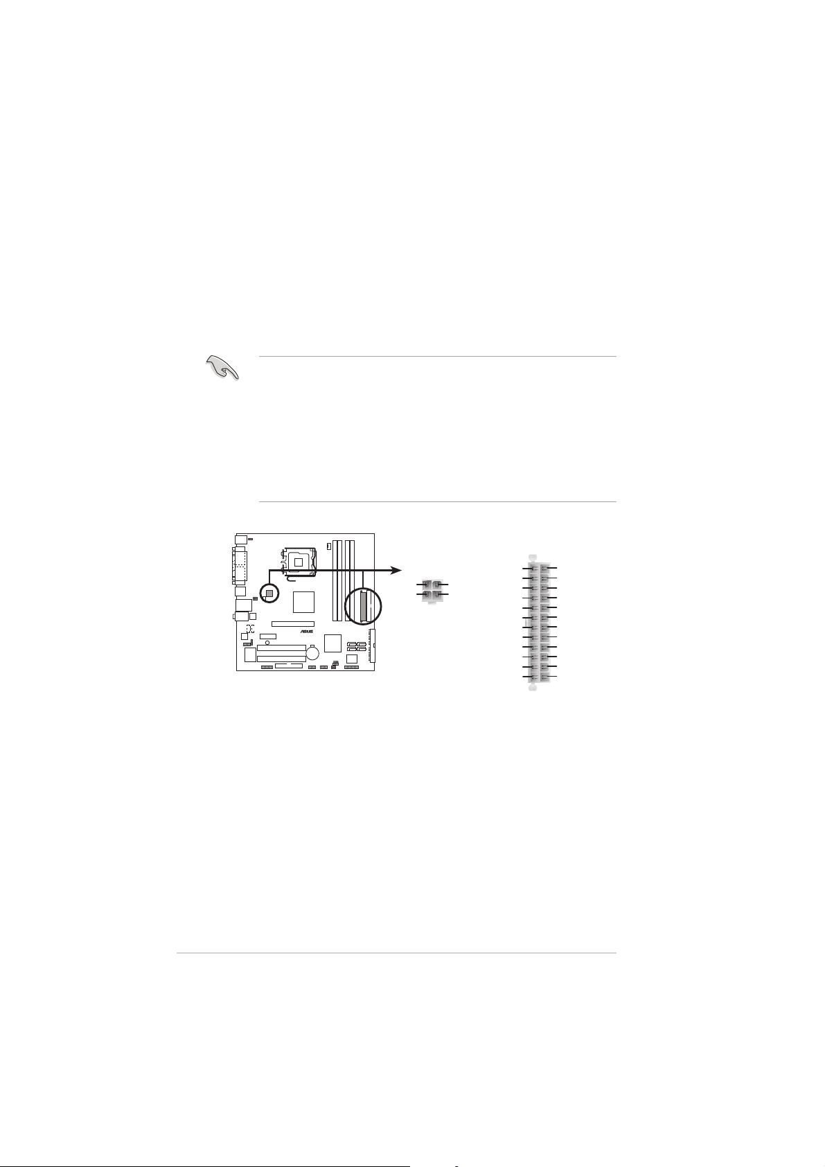
7.7.
ATX power connectors (24-pin EATXPWR,ATX power connectors (24-pin EATXPWR,
7.
ATX power connectors (24-pin EATXPWR,
7.7.
ATX power connectors (24-pin EATXPWR,ATX power connectors (24-pin EATXPWR,
4-pin ATX12V)4-pin ATX12V)
4-pin ATX12V)
4-pin ATX12V)4-pin ATX12V)
These connectors are for an ATX power supply. The plugs from the
power supply are designed to fit these connectors in only one
orientation. Find the proper orientation and push down firmly until the
connectors completely fit.
•
Do not forget to connect the 4-pin ATX +12 V power plug;
otherwise, the system will not boot up.
• When using an ATX 12 V PSU with 20-pin power plug, make sure
that it can provide 8 A on the +12 V lead and at least 1A on the
+5V standby lead (+5 VSB). The minimum recommended wattage is
300 W, or 350 W for a fully configured system. The system may
become unstable or may not boot up if the power is inadequate.
• You must install a Power Supply Unit (PSU) with a higher power
rating if you intend to install additional devices.
EATXPWR
1-301-30
1-30
1-301-30
GND
+12V DC
P5VDC-MX
®
P5VDC-MX ATX power connectors
ATX12V
GND
+12V DC
Chapter 1: Product introductionChapter 1: Product introduction
Chapter 1: Product introduction
Chapter 1: Product introductionChapter 1: Product introduction
+3 Volts
-12 Volts
Ground
PSON#
Ground
Ground
Ground
-5 Volts
+5 Volts
+5 Volts
+5 Volts
Ground
+3 Volts
+3 Volts
Ground
+5 Volts
Ground
+5 Volts
Ground
Power OK
+5V Standby
+12 Volts
+12 Volts
+3 Volts
Page 43

8.8.
GAME/MIDI port connector (16-1 pin GAME)GAME/MIDI port connector (16-1 pin GAME)
8.
GAME/MIDI port connector (16-1 pin GAME)
8.8.
GAME/MIDI port connector (16-1 pin GAME)GAME/MIDI port connector (16-1 pin GAME)
This connector is for a GAME/MIDI port. Connect the USB/GAME
module cable to this connector, then install the module to a slot
opening at the back of the system chassis. The GAME/MIDI port
connects a joystick or game pad for playing games, and MIDI devices
for playing or editing audio files.
P5VDC-MX
®
J2B1
J2CX
MIDI_OUT
J2CY
J2B2
+5V
MIDI_IN
GAME
P5VDC-MX Game connector
9.9.
USB connectors (10-1 pin USB56, USB78)USB connectors (10-1 pin USB56, USB78)
9.
USB connectors (10-1 pin USB56, USB78)
9.9.
USB connectors (10-1 pin USB56, USB78)USB connectors (10-1 pin USB56, USB78)
+5V
J1B1
J1CX
GND
GND
J1CY
J1B2
+5V
These connectors are for USB 2.0 ports. Connect the optional
USB/GAME module cable to any of these connectors, then install the
module to a slot opening at the back of the system chassis. These
USB connectors comply with USB 2.0 specification that supports up to
480 Mbps connection speed.
®
P5VDC-MX USB 2.0 connectors
Never connect a
damage the motherboard!
The USB/GAME module is purchased separately.
ASUS P5VDC-MXASUS P5VDC-MX
ASUS P5VDC-MX
ASUS P5VDC-MXASUS P5VDC-MX
P5VDC-MX
USB+5V
USB_P6-
USB_P6+
GND
NC
USB56
1
USB+5V
USB_P5-
1394 cable1394 cable
1394 cable to the USB connectors. Doing so will
1394 cable1394 cable
USB78
GND
USB_P5+
1
USB+5V
USB_P8-
USB_P8+
USB+5V
USB_P7-
USB_P7+
GND
GND
NC
1-311-31
1-31
1-311-31
Page 44

10.10.
Front panel audio connector (10-1 pin FP_AUDIO)Front panel audio connector (10-1 pin FP_AUDIO)
10.
Front panel audio connector (10-1 pin FP_AUDIO)
10.10.
Front panel audio connector (10-1 pin FP_AUDIO)Front panel audio connector (10-1 pin FP_AUDIO)
This is an interface for the front panel audio cable that allows
convenient connection and control of audio devices.
By default, the pins labeled LINE_OUT_R/BLINE_OUT_R and the pins
LINE_OUT_L/BLINE_OUT_L are shorted with jumper caps. Remove the
caps only when you are connecting the front panel audio cable.
P5VDC-MX
®
AGND
+5VA
BLINE_OUT_L
BLINE_OUT_R
FP_AUDIO
NC
MIC2
MICPWR
Line out_L
P5VDC-MX Front panel audio connector
11.11.
Chassis intrusion connector (4-1 pin CHASSIS)Chassis intrusion connector (4-1 pin CHASSIS)
11.
Chassis intrusion connector (4-1 pin CHASSIS)
11.11.
Chassis intrusion connector (4-1 pin CHASSIS)Chassis intrusion connector (4-1 pin CHASSIS)
Line out_R
This connector is for a chassis-mounted intrusion detection sensor or
switch. Connect one end of the chassis intrusion sensor or switch
cable to this connector. The chassis intrusion sensor or switch sends a
high-level signal to this connector when a chassis component is
removed or replaced. The signal is then generated as a chassis
intrusion event.
By default, the pins labeled “Chassis Signal” and “Ground” are shorted
with a jumper cap. Remove the jumper caps only when you intend to
use the chassis intrusion detection feature.
CHASSIS
1-321-32
1-32
1-321-32
P5VDC-MX
®
+5VSB_MB
P5VDC-MX Chassis intrusion connector
Chapter 1: Product introductionChapter 1: Product introduction
Chapter 1: Product introduction
Chapter 1: Product introductionChapter 1: Product introduction
Chassis Signal
GND
(Default)
Page 45

12.12.
System panel connector (20-1 pin F_PANEL)System panel connector (20-1 pin F_PANEL)
12.
System panel connector (20-1 pin F_PANEL)
12.12.
System panel connector (20-1 pin F_PANEL)System panel connector (20-1 pin F_PANEL)
This connector supports several chassis-mounted functions.
PLED
PLED+
P5VDC-MX
®
PANEL
IDE_LED+
IDE_LED
*
Requires an ATX power supply.
PLED-
IDE_LED-
SPEAKER
Ground
Speaker
Ground
+5V
PWR
Reset
Ground
Ground
RESET
PWRSW
P5VDC-MX System panel connector
The sytem panel connector is color-coded for easy connection. Refer to
the connector description below for details.
System power LED (Green 3-pin PLED)System power LED (Green 3-pin PLED)
•
System power LED (Green 3-pin PLED)
System power LED (Green 3-pin PLED)System power LED (Green 3-pin PLED)
This 3-pin connector is for the system power LED. Connect the
chassis power LED cable to this connector. The system power LED
lights up when you turn on the system power, and blinks when the
system is in sleep mode.
Hard disk drive activity (Red 2-pin IDE_LED)Hard disk drive activity (Red 2-pin IDE_LED)
•
Hard disk drive activity (Red 2-pin IDE_LED)
Hard disk drive activity (Red 2-pin IDE_LED)Hard disk drive activity (Red 2-pin IDE_LED)
This 2-pin connector is for the HDD Activity LED. Connect the HDD
Activity LED cable to this connector. The IDE LED lights up or flashes
when data is read from or written to the HDD.
System warning speaker (Orange 4-pin SPEAKER)System warning speaker (Orange 4-pin SPEAKER)
•
System warning speaker (Orange 4-pin SPEAKER)
System warning speaker (Orange 4-pin SPEAKER)System warning speaker (Orange 4-pin SPEAKER)
This 4-pin connector is for the chassis-mounted system warning
speaker. The speaker allows you to hear system beeps and warnings.
Power/Soft-off button (Yellow 2-pin PWRSW)Power/Soft-off button (Yellow 2-pin PWRSW)
•
Power/Soft-off button (Yellow 2-pin PWRSW)
Power/Soft-off button (Yellow 2-pin PWRSW)Power/Soft-off button (Yellow 2-pin PWRSW)
This connector is for the system power button. Pressing the power
button turns the system ON or puts the system in SLEEP or SOFT-OFF
mode depending on the BIOS settings. Pressing the power switch for
more than four seconds while the system is ON turns the system OFF.
Reset button (Blue 2-pin RESET)Reset button (Blue 2-pin RESET)
•
Reset button (Blue 2-pin RESET)
Reset button (Blue 2-pin RESET)Reset button (Blue 2-pin RESET)
This 2-pin connector is for the chassis-mounted reset button for
system reboot without turning off the system power.
ASUS P5VDC-MXASUS P5VDC-MX
ASUS P5VDC-MX
ASUS P5VDC-MXASUS P5VDC-MX
1-331-33
1-33
1-331-33
Page 46

1-341-34
1-34
1-341-34
Chapter 1: Product introductionChapter 1: Product introduction
Chapter 1: Product introduction
Chapter 1: Product introductionChapter 1: Product introduction
Page 47

This chapter tells how to change
the system settings through the BIOS
Setup menus. Detailed descriptions
of the BIOS parameters are also
provided.
BIOS setup
2
ASUS P5VDC-MXASUS P5VDC-MX
ASUS P5VDC-MX
ASUS P5VDC-MXASUS P5VDC-MX
2-12-1
2-1
2-12-1
Page 48

2.1 Managing and updating your BIOS
The following utilities allow you to manage and update the motherboard
Basic Input/Output System (BIOS) setup.
ASUS AFUDOS ASUS AFUDOS
1.
ASUS AFUDOS (Updates the BIOS in DOS mode using a bootable
ASUS AFUDOS ASUS AFUDOS
floppy disk.)
ASUS EZ Flash ASUS EZ Flash
2.
ASUS EZ Flash (Updates the BIOS using a floppy disk during POST.)
ASUS EZ Flash ASUS EZ Flash
ASUS CrashFree BIOS 2 ASUS CrashFree BIOS 2
3.
ASUS CrashFree BIOS 2 (Updates the BIOS using a bootable
ASUS CrashFree BIOS 2 ASUS CrashFree BIOS 2
floppy disk or the motherboard support CD when the BIOS file fails or
gets corrupted.)
ASUS Update ASUS Update
4.
ASUS Update (Updates the BIOS in Windows
ASUS Update ASUS Update
Refer to the corresponding sections for details on these utilities.
Save a copy of the original motherboard BIOS file to a bootable floppy
disk in case you need to restore the BIOS in the future. Copy the original
motherboard BIOS using the ASUS Update or AFUDOS utilities.
®
environment.)
2.1.12.1.1
2.1.1
2.1.12.1.1
Creating a bootable floppy diskCreating a bootable floppy disk
Creating a bootable floppy disk
Creating a bootable floppy diskCreating a bootable floppy disk
1. Do either one of the following to create a bootable floppy disk.
DOS environment
a. Insert a 1.44MB floppy disk into the drive.
b. At the DOS prompt, type format A:/S
then press <Enter>.
Windows® XP environment
a. Insert a 1.44 MB floppy disk to the floppy disk drive.
b. Click
ComputerComputer
Computer.
ComputerComputer
Start Start
Start from the Windows® desktop, then select
Start Start
MyMy
My
MyMy
c. Select the 3 1/2 Floppy Drive icon.
d. Click
e. Select
File File
File from the menu, then select
File File
Floppy DiskFloppy Disk
Floppy Disk window appears.
Floppy DiskFloppy Disk
Create an MS-DOS startup disk Create an MS-DOS startup disk
Create an MS-DOS startup disk from the format
Create an MS-DOS startup disk Create an MS-DOS startup disk
options field, then click
Start.
StartStart
StartStart
FormatFormat
Format. A
FormatFormat
Format 3 1/2Format 3 1/2
Format 3 1/2
Format 3 1/2Format 3 1/2
Windows® 2000 environment
To create a set of boot disks for Windows® 2000:
a. Insert a formatted, high density 1.44 MB floppy disk into the drive.
®
b. Insert the Windows
c. Click
StartStart
Start, then select
StartStart
2000 CD to the optical drive.
RunRun
Run.
RunRun
d. From the Open field, type
D:\bootdisk\makeboot a:
assuming that D: is your optical drive.
2-22-2
2-2
2-22-2
Chapter 2: BIOS setupChapter 2: BIOS setup
Chapter 2: BIOS setup
Chapter 2: BIOS setupChapter 2: BIOS setup
Page 49

e. Press <Enter>, then follow screen instructions to continue.
2. Copy the original or the latest motherboard BIOS file to the bootable
floppy disk.
2.1.22.1.2
2.1.2
2.1.22.1.2
ASUS EZ Flash utilityASUS EZ Flash utility
ASUS EZ Flash utility
ASUS EZ Flash utilityASUS EZ Flash utility
The ASUS EZ Flash feature allows you to update the BIOS without having to
go through the long process of booting from a floppy disk and using a
DOS-based utility. The EZ Flash utility is built-in the BIOS chip so it is
accessible by pressing <Alt> + <F2> during the Power-On Self Tests
(POST).
To use EZ Flash feature on motherboards with onboard VGA, you will not
see the screen display when the BIOS is refreshed. Install a graphics card
into the expansion slot to display BIOS update message.
To update the BIOS using EZ Flash:
1. Visit the ASUS website (www.asus.com) to download the latest BIOS
file for the motherboard and rename the same to
P5VDCMX.ROMP5VDCMX.ROM
P5VDCMX.ROM.
P5VDCMX.ROMP5VDCMX.ROM
2. Save the BIOS file to a floppy disk, then restart the system.
3. Press <Alt> + <F2> during POST to display the following.
EZFlash starting BIOS update
Checking for floppy...
4. Insert the floppy disk that contains the BIOS file to the floppy disk
drive. When the correct BIOS file is found, EZ Flash performs the BIOS
update process and automatically reboots the system when done.
EZFlash starting BIOS update
Checking for floppy...
Floppy found!
Reading file “P5VDCMX.ROM”. Completed.
Start erasing.......|
Start programming...|
Flashed successfully. Rebooting.
• Do not shutdown or reset the system while updating the BIOS to
prevent system boot failure!
• A “Floppy not found!” error message appears if there is no floppy
disk in the drive. A “P5VDCMX.ROM not found!” error message
appears if the correct BIOS file is not found in the floppy disk. Make
sure that you rename the BIOS file to P5VDCMX.ROM.
ASUS P5VDC-MXASUS P5VDC-MX
ASUS P5VDC-MX
ASUS P5VDC-MXASUS P5VDC-MX
2-32-3
2-3
2-32-3
Page 50

2.1.32.1.3
2.1.3
2.1.32.1.3
AFUDOS utilityAFUDOS utility
AFUDOS utility
AFUDOS utilityAFUDOS utility
The AFUDOS utility allows you to update the BIOS file in DOS environment
using a bootable floppy disk with the updated BIOS file. This utility also
allows you to copy the current BIOS file that you can use as backup when
the BIOS fails or gets corrupted during the updating process.
Copying the current BIOSCopying the current BIOS
Copying the current BIOS
Copying the current BIOSCopying the current BIOS
To copy the current BIOS file using the AFUDOS utility:
• Make sure that the floppy disk is not write-protected and has at
least 600 KB free space to save the file.
• The succeeding BIOS screens are for reference only. The actual BIOS
screen displays may not be exactly the same as shown.
1. Copy the AFUDOS utility (afudos.exe) from the motherboard support
CD to the bootable floppy disk you created earlier.
2. Boot the system in DOS mode, then at the prompt type:
afudos /o[filename]
where the [filename] is any user-assigned filename not more than
eight alphanumeric characters for the main filename and three
alphanumeric characters for the extension name.
A:\>afudos /oOLDBIOS1.ROM
Main filenameMain filename
Main filename
Main filenameMain filename
Extension nameExtension name
Extension name
Extension nameExtension name
3. Press <Enter>. The utility copies the current BIOS file to the floppy
disk.
A:\>afudos /oOLDBIOS1.ROM
AMI Firmware Update Utility - Version 1.10
Copyright (C) 2002 American Megatrends, Inc. All rights reserved.
Reading flash ..... done
A:\>
The utility returns to the DOS prompt after copying the current BIOS
file.
2-42-4
2-4
2-42-4
Chapter 2: BIOS setupChapter 2: BIOS setup
Chapter 2: BIOS setup
Chapter 2: BIOS setupChapter 2: BIOS setup
Page 51

Updating the BIOS fileUpdating the BIOS file
Updating the BIOS file
Updating the BIOS fileUpdating the BIOS file
To update the BIOS file using the AFUDOS utility:
1. Visit the ASUS website (www.asus.com) and download the latest BIOS
file for the motherboard. Save the BIOS file to a bootable floppy disk.
Write the BIOS filename on a piece of paper. You need to type the exact
BIOS filename at the DOS prompt.
2. Copy the AFUDOS utility (afudos.exe) from the motherboard support
CD to the bootable floppy disk you created earlier.
3. Boot the system in DOS mode, then at the prompt type:
afudos /i[filename]
where [filename] is the latest or the original BIOS file on the bootable
floppy disk.
A:\>afudos /iP5VDCMX.ROM
4. The utility verifies the file and starts updating the BIOS.
A:\>afudos /iP5VDCMX.ROM
AMI Firmware Update Utility - Version 1.10
Copyright (C) 2002 American Megatrends, Inc. All rights reserved.
Reading file ..... done
Erasing flash .... done
Writing flash .... 0x0008CC00 (9%)
Do not shut down or reset the system while updating the BIOS to
prevent system boot failure!
5. The utility returns to the DOS prompt after the BIOS update process is
completed. Reboot the system from the hard disk drive.
A:\>afudos /iP5VDCMX.ROM
AMI Firmware Update Utility - Version 1.10
Copyright (C) 2002 American Megatrends, Inc. All rights reserved.
Reading file ..... done
Erasing flash .... done
Writing flash .... 0x0008CC00 (9%)
Verifying flash .. done
A:\>
ASUS P5VDC-MXASUS P5VDC-MX
ASUS P5VDC-MX
ASUS P5VDC-MXASUS P5VDC-MX
2-52-5
2-5
2-52-5
Page 52

2.1.42.1.4
2.1.4
2.1.42.1.4
ASUS CrashFree BIOS 2 utilityASUS CrashFree BIOS 2 utility
ASUS CrashFree BIOS 2 utility
ASUS CrashFree BIOS 2 utilityASUS CrashFree BIOS 2 utility
The ASUS CrashFree BIOS 2 is an auto recovery tool that allows you to
restore the BIOS file when it fails or gets corrupted during the updating
process. You can update a corrupted BIOS file using the motherboard
support CD or the floppy disk that contains the updated BIOS file.
• Prepare the motherboard support CD or the floppy disk containing
the updated motherboard BIOS before using this utility.
• Make sure that you rename the original or updated BIOS file in the
floppy disk to
To use CrashFree BIOS2 feature on motherboards with onboard VGA,
you will not see the screen display when the BIOS crashes even when
you reboot the system. Install a graphics card into the expansion slot
before rebooting the computer to display BIOS recovery message.
Recovering the BIOS from a floppy diskRecovering the BIOS from a floppy disk
Recovering the BIOS from a floppy disk
Recovering the BIOS from a floppy diskRecovering the BIOS from a floppy disk
P5VDCMX.ROMP5VDCMX.ROM
P5VDCMX.ROM.
P5VDCMX.ROMP5VDCMX.ROM
To recover the BIOS from a floppy disk:
1. Turn on the system.
2. Insert the floppy disk with the original or updated BIOS file to the
floppy disk drive.
3. The utility displays the following message and automatically checks
the floppy disk for the original or updated BIOS file.
Bad BIOS checksum. Starting BIOS recovery...
Checking for floppy...
When found, the utility reads the BIOS file and starts flashing the
corrupted BIOS file.
Bad BIOS checksum. Starting BIOS recovery...
Checking for floppy...
Floppy found!
Reading file “P5VDCMX.ROM”. Completed.
Start flashing...
DO NOT shut down or reset the system while updating the BIOS! Doing
so can cause system boot failure!
4. Restart the system after the utility completes the updating process.
2-62-6
2-6
2-62-6
Chapter 2: BIOS setupChapter 2: BIOS setup
Chapter 2: BIOS setup
Chapter 2: BIOS setupChapter 2: BIOS setup
Page 53

Recovering the BIOS from the support CDRecovering the BIOS from the support CD
Recovering the BIOS from the support CD
Recovering the BIOS from the support CDRecovering the BIOS from the support CD
To recover the BIOS from the support CD:
1. Remove any floppy disk from the floppy disk drive, then turn on the
system.
2. Insert the support CD to the optical drive.
3. The utility displays the following message and automatically checks
the floppy disk for the original or updated BIOS file.
Bad BIOS checksum. Starting BIOS recovery...
Checking for floppy...
When no floppy disk is found, the utility automatically checks the
optical drive for the original or updated BIOS file. The utility then
updates the corrupted BIOS file.
Bad BIOS checksum. Starting BIOS recovery...
Checking for floppy...
Floppy not found!
Checking for CD-ROM...
CD-ROM found!
Reading file “P5VDCMX.ROM”. Completed.
Start flashing...
DO NOT shut down or reset the system while updating the BIOS! Doing
so can cause system boot failure!
4. Restart the system after the utility completes the updating process.
The recovered BIOS may not be the latest BIOS version for this
motherboard. Visit the ASUS website (www.asus.com) to download the
latest BIOS file.
ASUS P5VDC-MXASUS P5VDC-MX
ASUS P5VDC-MX
ASUS P5VDC-MXASUS P5VDC-MX
2-72-7
2-7
2-72-7
Page 54

2.1.52.1.5
2.1.5
2.1.52.1.5
The ASUS Update is a utility that allows you to manage, save, and update
the motherboard BIOS in Windows® environment. The ASUS Update utility
allows you to:
This utility is available in the support CD that comes with the motherboard
package.
Installing ASUS UpdateInstalling ASUS Update
Installing ASUS Update
Installing ASUS UpdateInstalling ASUS Update
To install ASUS Update:
ASUS Update utilityASUS Update utility
ASUS Update utility
ASUS Update utilityASUS Update utility
• Save the current BIOS file
• Download the latest BIOS file from the Internet
• Update the BIOS from an updated BIOS file
• Update the BIOS directly from the Internet, and
• View the BIOS version information.
ASUS Update requires an Internet connection either through a network
or an Internet Service Provider (ISP).
1. Place the support CD in the optical drive. The
2. Click the
VX.XX.XXVX.XX.XX
VX.XX.XX. See page 3-4 for the
VX.XX.XXVX.XX.XX
3. The ASUS Update utility is copied to your system.
2-82-8
2-8
2-82-8
Utilities Utilities
Utilities tab, then click
Utilities Utilities
Quit all Windows® applications before you update the BIOS using this
utility.
Install ASUS UpdateInstall ASUS Update
Install ASUS Update
Install ASUS UpdateInstall ASUS Update
Utilities Utilities
Utilities screen menu.
Utilities Utilities
Drivers Drivers
Drivers menu appears.
Drivers Drivers
Chapter 2: BIOS setupChapter 2: BIOS setup
Chapter 2: BIOS setup
Chapter 2: BIOS setupChapter 2: BIOS setup
Page 55

Updating the BIOS through the InternetUpdating the BIOS through the Internet
Updating the BIOS through the Internet
Updating the BIOS through the InternetUpdating the BIOS through the Internet
To update the BIOS through the Internet:
®
1. Launch the ASUS Update utility from the Windows
Start Start
Start >
Start Start
Programs Programs
Programs >
Programs Programs
ASUS ASUS
ASUS >
ASUS ASUS
ASUSUpdate ASUSUpdate
ASUSUpdate >
ASUSUpdate ASUSUpdate
desktop by clicking
ASUSUpdateASUSUpdate
ASUSUpdate. The
ASUSUpdateASUSUpdate
ASUS Update main window appears.
2. Select
Update BIOS fromUpdate BIOS from
Update BIOS from
Update BIOS fromUpdate BIOS from
the Internet the Internet
the Internet option from the
the Internet the Internet
drop-down menu, then click
NextNext
Next.
NextNext
ASUS P5VDC-MXASUS P5VDC-MX
ASUS P5VDC-MX
ASUS P5VDC-MXASUS P5VDC-MX
3. Select the ASUS FTP site
nearest you to avoid network
traffic, or click
NextNext
Click
Next.
NextNext
Auto SelectAuto Select
Auto Select.
Auto SelectAuto Select
2-92-9
2-9
2-92-9
Page 56
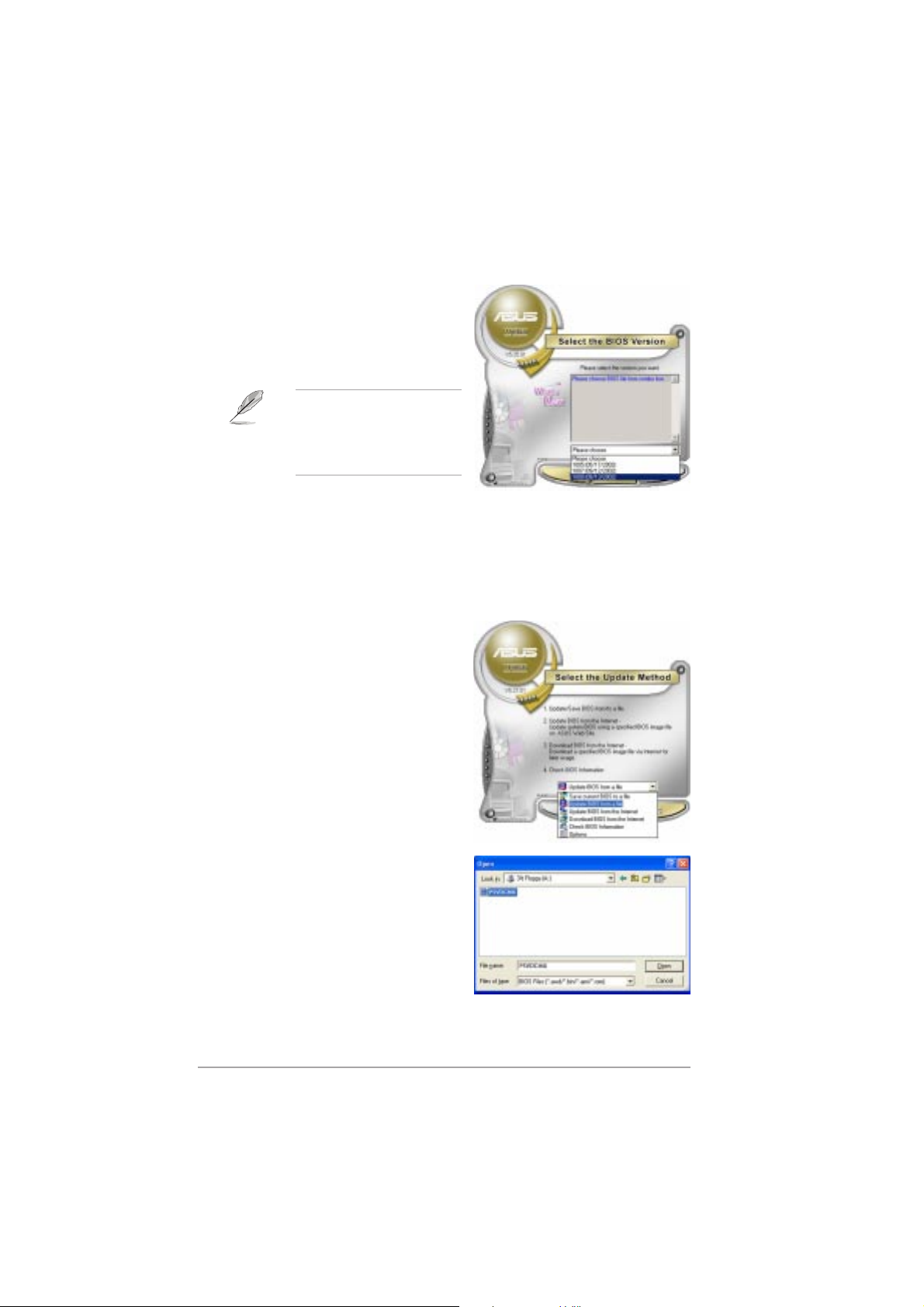
4. From the FTP site, select the
BIOS version that you wish to
download. Click Next.
5. Follow the screen instructions to
complete the update process.
The ASUS Update utility is
capable of updating itself
through the Internet. Always
update the utility to avail all
its features.
Updating the BIOS through a BIOS fileUpdating the BIOS through a BIOS file
Updating the BIOS through a BIOS file
Updating the BIOS through a BIOS fileUpdating the BIOS through a BIOS file
To update the BIOS through a BIOS file:
®
1. Launch the ASUS Update utility from the Windows
clicking
ASUSUpdateASUSUpdate
ASUSUpdate. The ASUS Update main window appears.
ASUSUpdateASUSUpdate
2. Select
file file
file option from the drop-down
file file
Start Start
Start >
Start Start
Update BIOS from aUpdate BIOS from a
Update BIOS from a
Update BIOS from aUpdate BIOS from a
menu, then click
Programs Programs
Programs >
Programs Programs
NextNext
Next.
NextNext
ASUS ASUS
ASUS >
ASUS ASUS
ASUSUpdate ASUSUpdate
ASUSUpdate >
ASUSUpdate ASUSUpdate
desktop by
3. Locate the BIOS file from the
Open Open
Open window, then click
Open Open
4. Follow the screen instructions to
complete the update process.
2-102-10
2-10
2-102-10
SaveSave
Save.
SaveSave
Chapter 2: BIOS setupChapter 2: BIOS setup
Chapter 2: BIOS setup
Chapter 2: BIOS setupChapter 2: BIOS setup
Page 57

2.2 BIOS setup program
This motherboard supports a programmable firmware chip that you can
update using the provided utility described in section “2.1 Managing and
updating your BIOS.”
Use the BIOS Setup program when you are installing a motherboard,
reconfiguring your system, or prompted to “Run Setup”. This section
explains how to configure your system using this utility.
Even if you are not prompted to use the Setup program, you can change
the configuration of your computer in the future. For example, you can
enable the security password feature or change the power management
settings. This requires you to reconfigure your system using the BIOS
Setup program so that the computer can recognize these changes and
record them in the CMOS RAM of the firmware hub.
The firmware hub on the motherboard stores the Setup utility. When you
start up the computer, the system provides you with the opportunity to
run this program. Press <Del>
enter the Setup utility; otherwise, POST continues with its test routines.
If you wish to enter Setup after POST, restart the system by pressing
<Ctrl+Alt+Delete>, or by pressing the reset button on the system chassis.
You can also restart by turning the system off and then back on. Do this
last option only if the first two failed.
The Setup program is designed to make it as easy to use as possible. Being
a menu-driven program, it lets you scroll through the various sub-menus
and make your selections from the available options using the navigation
keys.
during the Power-On Self-Test (POST) to
• The default BIOS settings for this motherboard apply for most
conditions to ensure optimum performance. If the system becomes
unstable after changing any BIOS settings, load the default settings
to ensure system compatibility and stability. Select the
Default SettingsDefault Settings
Default Settings item under the Exit Menu. See section “2.7 Exit
Default SettingsDefault Settings
Menu.”
• The BIOS setup screens shown in this section are for reference
purposes only, and may not exactly match what you see on your
screen.
• Visit the ASUS website (www.asus.com) to download the latest BIOS
file for this motherboard and .
ASUS P5VDC-MXASUS P5VDC-MX
ASUS P5VDC-MX
ASUS P5VDC-MXASUS P5VDC-MX
LoadLoad
Load
LoadLoad
2-112-11
2-11
2-112-11
Page 58
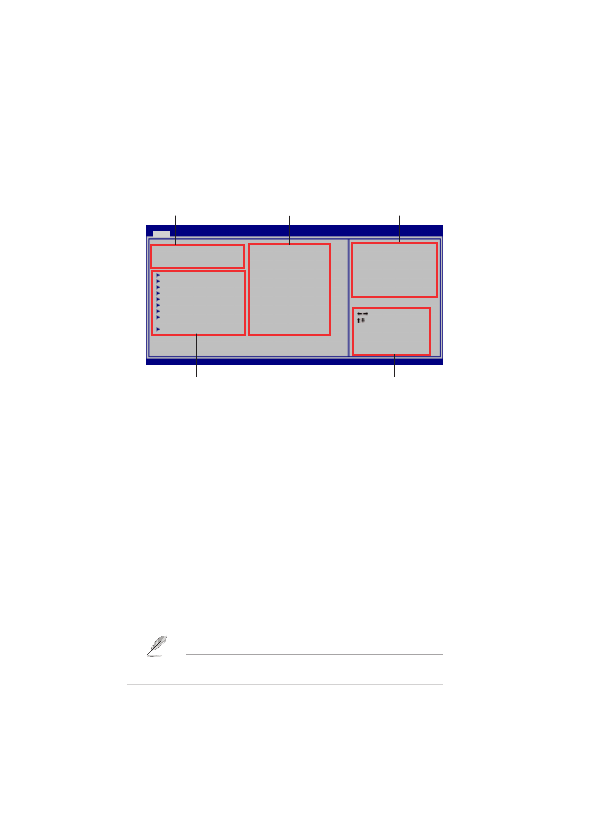
2.2.12.2.1
2.2.1
2.2.12.2.1
BIOS menu screenBIOS menu screen
BIOS menu screen
BIOS menu screenBIOS menu screen
Menu itemsMenu items
Menu items
Menu itemsMenu items
Main Advanced Power Boot Exit
System Time [10:55:25]
System Date [Thu 09/15/2005]
Legacy Diskette A [1.44M, 3.5 in]
Primary IDE Master [ST320410A]
Primary IDE Slave [ASUS CD-S520/A]
Secondary IDE Master [Not Detected]
Secondary IDE Slave [Not Detected]
Third IDE Master [Not Detected]
Third IDE Slave [Not Detected]
Fourth IDE Master [Not Detected]
Fourth IDE Slave [Not Detected]
System Information
Sub-menu itemsSub-menu items
Sub-menu items
Sub-menu itemsSub-menu items
2.2.22.2.2
2.2.2
2.2.22.2.2
Menu barMenu bar
Menu bar
Menu barMenu bar
v02.58 (C)Copyright 1985-2004, American Megatrends, Inc.
Menu barMenu bar
Menu bar
Menu barMenu bar
Configuration fieldsConfiguration fields
Configuration fields
Configuration fieldsConfiguration fields
BIOS SETUP UTILITY
General helpGeneral help
General help
General helpGeneral help
Use [ENTER], [TAB] or
[SHIFT-TAB] to select
a field.
Use [+] or [-] to
configure the System
Time.
Select Screen
Select Item
+- Change Field
Tab Select Field
F1 General Help
F10 Save and Exit
ESC Exit
Navigation keysNavigation keys
Navigation keys
Navigation keysNavigation keys
The menu bar on top of the screen has the following main items:
MainMain
Main For changing the basic system configuration
MainMain
AdvancedAdvanced
Advanced For changing the advanced system settings
AdvancedAdvanced
PowerPower
Power For changing the advanced power management (APM)
PowerPower
configuration
BootBoot
Boot For changing the system boot configuration
BootBoot
ExitExit
Exit For selecting the exit options and loading default
ExitExit
settings
To select an item on the menu bar, press the right or left arrow key on the
keyboard until the desired item is highlighted.
2.2.32.2.3
2.2.3
2.2.32.2.3
Navigation keysNavigation keys
Navigation keys
Navigation keysNavigation keys
At the bottom right corner of a menu screen are the navigation keys for
that particular menu. Use the navigation keys to select items in the menu
and change the settings.
Some of the navigation keys differ from one screen to another.
2-122-12
2-12
2-122-12
Chapter 2: BIOS setupChapter 2: BIOS setup
Chapter 2: BIOS setup
Chapter 2: BIOS setupChapter 2: BIOS setup
Page 59

2.2.42.2.4
2.2.4
2.2.42.2.4
Menu itemsMenu items
Menu items
Menu itemsMenu items
The highlighted item on the menu bar
displays the specific items for that menu.
For example, selecting
Main Main
Main shows the
Main Main
Main menu items.
The other items (Advanced, Power, Boot,
System Time [11:10:19]
System Date [Thu 03/27/2003]
Legacy Diskette A [1.44M, 3.5 in]
Language [English]
Primary IDE Master :[ST320413A]
Primary IDE Slave :[ASUS CD-S340]
Secondary IDE Master :[Not Detected]
Secondary IDE Slave :[Not Detected]
Third IDE Master :[Not Detected]
Fourth IDE Master :[Not Detected]
IDE Configuration
System Information
Use [ENTER], [TAB]
or [SHIFT-TAB] to
select a field.
Use [+] or [-] to
configure system time.
Select Screen
Select Item
+- Change Field
Tab Select Field
F1 General Help
F10 Save and Exit
ESC Exit
and Exit) on the menu bar have their
respective menu items.
2.2.52.2.5
2.2.5
2.2.52.2.5
Sub-menu itemsSub-menu items
Sub-menu items
Sub-menu itemsSub-menu items
Main menu itemsMain menu items
Main menu items
Main menu itemsMain menu items
A solid triangle before each item on any menu screen means that the iteam
has a sub-menu. To display the sub-menu, select the item and press
<Enter>.
2.2.62.2.6
2.2.6
2.2.62.2.6
Configuration fieldsConfiguration fields
Configuration fields
Configuration fieldsConfiguration fields
These fields show the values for the menu items. If an item is userconfigurable, you can change the value of the field opposite the item. You
cannot select an item that is not user-configurable.
A configurable field is enclosed in brackets, and is highlighted when
selected. To change the value of a field, select it then press <Enter> to
display a list of options. Refer to “2.2.7 Pop-up window.”
2.2.72.2.7
2.2.7
2.2.72.2.7
Pop-up windowPop-up window
Pop-up window
Pop-up windowPop-up window
Select a menu item then press <Enter> to display a pop-up window with
the configuration options for that item.
2.2.82.2.8
2.2.8
2.2.82.2.8
Scroll barScroll bar
Scroll bar
Scroll barScroll bar
A scroll bar appears on the right side
of a menu screen when there are
items that do not fit on the screen.
Press the
Up/Down arrow keys or <Page Up> /
<Page Down> keys to display the
other items on the screen.
2.2.92.2.9
2.2.9
2.2.92.2.9
General helpGeneral help
General help
General helpGeneral help
At the top right corner of the menu
screen is a brief description of the
selected item.
ASUS P5VDC-MXASUS P5VDC-MX
ASUS P5VDC-MX
ASUS P5VDC-MXASUS P5VDC-MX
Advanced Chipset settings
WARNING: Setting wrong values in the sections below
may cause system to malfunction.
Configure DRAM Timing by SPD [Enabled]
Memory Acceleration Mode [Auto]
DRAM Idle Timer [Auto]
DRAm Refresh Rate [Auto]
Graphic Adapter Priority [AGP/PCI]
Graphics Aperture Size [ 64 MB]
Spread Spectrum [Enabled]
ICH Delayed Transaction [Enabled]
MPS Revision [1.4]
Pop-up windowPop-up window
Pop-up window
Pop-up windowPop-up window
Scroll barScroll bar
Scroll bar
Scroll barScroll bar
Select Screen
Select Item
+- Change Option
F1 General Help
F10 Save and Exit
ESC Exit
2-132-13
2-13
2-132-13
Page 60

2.3 Main menu
When you enter the BIOS Setup program, the Main menu screen appears,
giving you an overview of the basic system information.
Refer to section “2.2.1 BIOS menu screen” for information on the menu
screen items and how to navigate through them.
Main Advanced Power Boot Exit
System Time [10:55:25]
System Date [Thu 07/21/2005]
Legacy Diskette A [1.44M, 3.5 in]
Primary IDE Master [ST320410A]
Primary IDE Slave [ASUS CD-S520/A]
Secondary IDE Master [Not Detected]
Secondary IDE Slave [Not Detected]
Third IDE Master [Not Detected]
Third IDE Slave [Not Detected]
Fourth IDE Master [Not Detected]
Fourth IDE Slave [Not Detected]
System Information
v02.58 (C)Copyright 1985-2004, American Megatrends, Inc.
2.3.12.3.1
2.3.1
2.3.12.3.1
System Time [xx:xx:xxxx]System Time [xx:xx:xxxx]
System Time [xx:xx:xxxx]
System Time [xx:xx:xxxx]System Time [xx:xx:xxxx]
BIOS SETUP UTILITY
Use [ENTER], [TAB] or
[SHIFT-TAB] to select
a field.
Use [+] or [-] to
configure the System
Time.
Select Screen
Select Item
+- Change Field
Tab Select Field
F1 General Help
F10 Save and Exit
ESC Exit
Allows you to set the system time.
2.3.22.3.2
2.3.2
2.3.22.3.2
System Date [Day xx/xx/xxxx]System Date [Day xx/xx/xxxx]
System Date [Day xx/xx/xxxx]
System Date [Day xx/xx/xxxx]System Date [Day xx/xx/xxxx]
Allows you to set the system date.
2.3.32.3.3
2.3.3
2.3.32.3.3
Legacy Diskette A [1.44M, 3.5 in.]Legacy Diskette A [1.44M, 3.5 in.]
Legacy Diskette A [1.44M, 3.5 in.]
Legacy Diskette A [1.44M, 3.5 in.]Legacy Diskette A [1.44M, 3.5 in.]
Sets the type of floppy drive installed. Configuration options: [Disabled]
[360K, 5.25 in.] [1.2M , 5.25 in.] [720K , 3.5 in.] [1.44M, 3.5 in.]
[2.88M, 3.5␣ in.]
2-142-14
2-14
2-142-14
Chapter 2: BIOS setupChapter 2: BIOS setup
Chapter 2: BIOS setup
Chapter 2: BIOS setupChapter 2: BIOS setup
Page 61

2.3.42.3.4
2.3.4
2.3.42.3.4
Primary and Secondary IDE Master/SlavePrimary and Secondary IDE Master/Slave
Primary and Secondary IDE Master/Slave
Primary and Secondary IDE Master/SlavePrimary and Secondary IDE Master/Slave
While entering Setup, the BIOS automatically detects the presence of IDE
devices. There is a separate sub-menu for each IDE device. Select a device
item then press <Enter> to display the IDE device information.
Select the type of
Type [Auto]
LBA/Large Mode [Auto]
Block(Multi-sector Transfer)M [Auto]
PIO Mode [Auto]
DMA Mode [Auto]
Smart Monitoring [Auto]
32Bit Data Transfer [Enabled]
device connected to
the system.
The BIOS automatically detects the values opposite the dimmed items
(Device, Vendor, Size, LBA Mode, Block Mode, PIO Mode, Async DMA, Ultra
DMA, and SMART monitoring). These values are not user-configurable.
These items show N/A if no IDE device is installed in the system.
Type [Auto]Type [Auto]
Type [Auto]
Type [Auto]Type [Auto]
Selects the type of IDE drive. Setting to Auto allows automatic selection of
the appropriate IDE device type. Select CDROM if you are specifically
configuring a CD-ROM drive. Select ARMD (ATAPI Removable Media Device)
if your device is either a ZIP, LS-120, or MO drive.
Configuration options: [Not Installed] [Auto] [CDROM] [ARMD]
LBA/Large Mode [Auto]LBA/Large Mode [Auto]
LBA/Large Mode [Auto]
LBA/Large Mode [Auto]LBA/Large Mode [Auto]
Enables or disables the LBA mode. Setting to Auto enables the LBA mode if
the device supports this mode, and if the device was not previously
formatted with LBA mode disabled.
Configuration options: [Disabled] [Auto]
Block (Multi-sector Transfer) M [Auto]Block (Multi-sector Transfer) M [Auto]
Block (Multi-sector Transfer) M [Auto]
Block (Multi-sector Transfer) M [Auto]Block (Multi-sector Transfer) M [Auto]
Enables or disables data multi-sectors transfers. When set to Auto, the
data transfer from and to the device occurs multiple sectors at a time if
the device supports multi-sector transfer feature. When set to [Disabled],
the data transfer from and to the device occurs one sector at a time.
Configuration options: [Disabled] [Auto]
ASUS P5VDC-MXASUS P5VDC-MX
ASUS P5VDC-MX
ASUS P5VDC-MXASUS P5VDC-MX
2-152-15
2-15
2-152-15
Page 62

PIO Mode [Auto]PIO Mode [Auto]
PIO Mode [Auto]
PIO Mode [Auto]PIO Mode [Auto]
Selects the PIO mode.
Configuration options: [Auto] [0] [1] [2] [3] [4]
DMA Mode [Auto]DMA Mode [Auto]
DMA Mode [Auto]
DMA Mode [Auto]DMA Mode [Auto]
Selects the DMA mode. Configuration options: [Auto] [SWDMA0]
[SWDMA1] [SWDMA2] [MWDMA0] [MWDMA1] [MWDMA2] [UDMA0]
[UDMA1] [UDMA2] [UDMA3] [UDMA04] [UDMA5] [UDMA6]
SMART Monitoring [Auto]SMART Monitoring [Auto]
SMART Monitoring [Auto]
SMART Monitoring [Auto]SMART Monitoring [Auto]
Sets the Smart Monitoring, Analysis, and Reporting Technology.
Configuration options: [Auto] [Disabled] [Enabled]
32Bit Data Transfer [Enabled]32Bit Data Transfer [Enabled]
32Bit Data Transfer [Enabled]
32Bit Data Transfer [Enabled]32Bit Data Transfer [Enabled]
Enables or disables 32-bit data transfer.
Configuration options: [Disabled] [Enabled]
2.3.52.3.5
2.3.5
2.3.52.3.5
This menu gives you an overview of the general system specifications. The
BIOS automatically detects the items in this menu.
AMIBIOS
Version : 0110
Build Date : 10/05/05
Processor
Type : Genuine Intel(R) CPU 3.80GHz
Speed : 3914 MHz
Count : 1
System Memory
Usable Size : 192MB
AMI BIOSAMI BIOS
AMI BIOS
AMI BIOSAMI BIOS
Displays the auto-detected BIOS information
ProcessorProcessor
Processor
ProcessorProcessor
Displays the auto-detected CPU specification
System MemorySystem Memory
System Memory
System MemorySystem Memory
Displays the auto-detected system memory
System InformationSystem Information
System Information
System InformationSystem Information
2-162-16
2-16
2-162-16
Chapter 2: BIOS setupChapter 2: BIOS setup
Chapter 2: BIOS setup
Chapter 2: BIOS setupChapter 2: BIOS setup
Page 63

2.4 Advanced menu
The Advanced menu items allow you to change the settings for the CPU
and other system devices.
Take caution when changing the settings of the Advanced menu items.
Incorrect field values may cause the system to malfunction.
JumperFree Configuration
USB Configuration
CPU Configuration
Chipset
Onboard Devices Configuration
PCIPnP
2.4.12.4.1
2.4.1
2.4.12.4.1
Configure System Frequency/Voltage
Overclock Mode [Manual]
Overclock Mode [Auto]Overclock Mode [Auto]
Overclock Mode [Auto]
Overclock Mode [Auto]Overclock Mode [Auto]
JumperFree ConfigurationJumperFree Configuration
JumperFree Configuration
JumperFree ConfigurationJumperFree Configuration
Select the target CPU
frequency, and the
relevant parameters
will be auto-adjusted.
Frequencies higher
than CPU manufacturer
recommends are not
guaranteed to be
stable. If the system
becomes unstable,
return to the default.
Allows selection of CPU overclocking options to achieve desired CPU
internal frequency. Select either one of the preset overclocking
configuration options:
Manual Manual
Manual - allows you to individually set overclocking parameters.
Manual Manual
Auto Auto
Auto - loads the optimal settings for the system.
Auto Auto
CPU Frequency [200 MHz]
Displays the frequency sent by the clock generator to the system bus
and PCI bus. The value of this item is auto-detected by the BIOS. Use
<+><+>
the
< + > and
<+><+>
<-><->
< - > keys to adjust the CPU frequency. You can also
<-><->
type the desired CPU frequency using the numeric keypad. The values
range from 100 to 400.
ASUS P5VDC-MXASUS P5VDC-MX
ASUS P5VDC-MX
ASUS P5VDC-MXASUS P5VDC-MX
2-172-17
2-17
2-172-17
Page 64

2.4.22.4.2
2.4.2
2.4.22.4.2
USB ConfigurationUSB Configuration
USB Configuration
USB ConfigurationUSB Configuration
The items in this menu allows you to change the USB-related features.
Select an item then press Enter to display the configuration options.
Advanced
USB Configuration
Module Version - 2.24.0-11.4
USB Devices Enabled:
None
USB 1.1 Ports Configuration [Enabled]
USB 2.0 Ports Enable [Enable]
Legacy USB Support [Auto]
USB 2.0 Controller Mode [Hispeed]
BIOS EHCI Hand-Off [Enabled]
v02.58 (C)Copyright 1985-2004, American Megatrends, Inc.
The Module Version and USB Devices Enabled items show the
auto-detected values. If no USB device is detected, the item shows
None.
USB 1.1 Ports Configuration [Enabled]USB 1.1 Ports Configuration [Enabled]
USB 1.1 Ports Configuration [Enabled]
USB 1.1 Ports Configuration [Enabled]USB 1.1 Ports Configuration [Enabled]
BIOS SETUP UTILITY
Enables 1.1 USB host
controllers.
Select Screen
Select Item
+- Change Option
F1 General Help
F10 Save and Exit
ESC Exit
Allows you to choose the number of USB 1.1 ports to enable. Setting to
[Disabled] disables the USB 1.1 host controllers.
Configuration options: [Disabled] [Enabled]
USB 2.0 Ports Enable [Enable]USB 2.0 Ports Enable [Enable]
USB 2.0 Ports Enable [Enable]
USB 2.0 Ports Enable [Enable]USB 2.0 Ports Enable [Enable]
Allows you to enable or disable the USB 2.0 host controllers.
Configuration options: [Disabled] [Enable]
Legacy USB Support [Auto]Legacy USB Support [Auto]
Legacy USB Support [Auto]
Legacy USB Support [Auto]Legacy USB Support [Auto]
Allows you to enable or disable support for legacy USB devices. Setting to
Auto allows the system to detect the presence of USB devices at startup.
If detected, the USB controller legacy mode is enabled. If no USB device is
detected, the legacy USB support is disabled.
Configuration options: [Disabled] [Enabled] [Auto]
USB 2.0 Controller Mode [Hispeed]USB 2.0 Controller Mode [Hispeed]
USB 2.0 Controller Mode [Hispeed]
USB 2.0 Controller Mode [Hispeed]USB 2.0 Controller Mode [Hispeed]
Allows you to configure the USB 2.0 controller in HiSpeed (480 Mbps) or
Full Speed (12 Mbps). Configuration options: [FullSpeed] [HiSpeed ]
2-182-18
2-18
2-182-18
Chapter 2: BIOS SetupChapter 2: BIOS Setup
Chapter 2: BIOS Setup
Chapter 2: BIOS SetupChapter 2: BIOS Setup
Page 65

BIOS EHCI Hand-Off [Enabled]BIOS EHCI Hand-Off [Enabled]
BIOS EHCI Hand-Off [Enabled]
BIOS EHCI Hand-Off [Enabled]BIOS EHCI Hand-Off [Enabled]
Allows you to enable support for operating systems without an EHCI
hand-off feature. Configuration options: [Disabled] [Enabled]
Do not disable the BIOS EHCI Hand-Off option if you are running a
Windows® operating system with USB device.
2.4.32.4.3
2.4.3
2.4.32.4.3
CPU ConfigurationCPU Configuration
CPU Configuration
CPU ConfigurationCPU Configuration
The items in this menu show the CPU-related information auto-detected by
BIOS.
Configure Advanced CPU settings
Manufacturer: Intel
Brand String: Genuine Intel(R) CPU 3.80GHz
Frequency : 3914Mhz
FSB Speed : 825Mhz
Cache L1 : 16 KB
Cache L2 : 2048 KB
Cache L3 : 0 KB
Ratio Status: Unlocked (Max:19, Min:14)
Ratio Actual Value: 19
Ratio CMOS Setting: [ 19]
Max CPUID Value Limit: [Disabled]
Excute Disable Function [Disabled]
Hyper Threading Technology [Disabled]
Ratio CMOS Setting [ 16]Ratio CMOS Setting [ 16]
Ratio CMOS Setting [ 16]
Ratio CMOS Setting [ 16]Ratio CMOS Setting [ 16]
Sets the ratio between the CPU Core Clock and the Front Side Bus
frequency. The default value of this item is auto-detected by BIOS. Use the
<+> or <-> keys to adjust the values.
Max CPUID Value Limit [Disabled]Max CPUID Value Limit [Disabled]
Max CPUID Value Limit [Disabled]
Max CPUID Value Limit [Disabled]Max CPUID Value Limit [Disabled]
Enable this item to boot legacy operating systems that cannot support
CPUs with extended CPUID functions.
Configuration options: [Disabled] [Enabled]
ASUS P5VDC-MXASUS P5VDC-MX
ASUS P5VDC-MX
ASUS P5VDC-MXASUS P5VDC-MX
2-192-19
2-19
2-192-19
Page 66

Execute Disable Function [Disabled]Execute Disable Function [Disabled]
Execute Disable Function [Disabled]
Execute Disable Function [Disabled]Execute Disable Function [Disabled]
Enables or disables the Execute Disable function. This item appears only
when you install a processor with the Execute Disable function.
Configuration options: [Disabled] [Enabled]
Hyper-Threading Technology [Disabled]Hyper-Threading Technology [Disabled]
Hyper-Threading Technology [Disabled]
Hyper-Threading Technology [Disabled]Hyper-Threading Technology [Disabled]
This item allows you to enable or disable the processor Hyper-Threading
Technology. Configuration options: [Disabled] [Enabled]
2.4.42.4.4
2.4.4
2.4.42.4.4
ChipsetChipset
Chipset
ChipsetChipset
The Chipset menu items allow you to change the advanced chipset
settings. Select an item then press <Enter> to display the sub-menu.
Advanced
Advanced Chipset Settings
WARNING: Setting wrong values in below sections may
NorthBridge ConfigurationNorthBridge Configuration
NorthBridge Configuration
NorthBridge ConfigurationNorthBridge Configuration
NorthBridge Configuration
cause system to malfunction.
Northbridge Configuration
Southbridge Configuration
v02.58 (C)Copyright 1985-2004, American Megatrends, Inc.
Advanced
DRAM Clock/Timing Configuration
AGP & P2P Bridge Configuration
BIOS SETUP UTILITY
BIOS SETUP UTILITY
Options for NB
Select Screen
Select Item
Enter Go to Subscreen
F1 General Help
F10 Save and Exit
ESC Exit
Options for DRAM
2-202-20
2-20
2-202-20
Chapter 2: BIOS SetupChapter 2: BIOS Setup
Chapter 2: BIOS Setup
Chapter 2: BIOS SetupChapter 2: BIOS Setup
Page 67

DRAM Frequency/Timing ConfigurationDRAM Frequency/Timing Configuration
DRAM Frequency/Timing Configuration
DRAM Frequency/Timing ConfigurationDRAM Frequency/Timing Configuration
Advanced
DRAM Frequency/Timing Configuration
DRAM Frequency [Auto]
DRAM Timing [Auto]
DRAM Frequency [Auto]DRAM Frequency [Auto]
DRAM Frequency [Auto]
DRAM Frequency [Auto]DRAM Frequency [Auto]
BIOS SETUP UTILITY
Sets the DDR/DDR2 operating frequency. Configuration options when install
DDR memory modules: [Auto] [266 MHz] [333 MHz] [400 MHz];
Configuration options when install DDR2 memory modules: [Auto]
[400 MHz] [533 MHz]
DRAM Timing [Auto]DRAM Timing [Auto]
DRAM Timing [Auto]
DRAM Timing [Auto]DRAM Timing [Auto]
Configuration options: [Manual] [Auto]
The following items only appear when the DRAM Timing item is set to
[Manual].
DRAM CAS# Latency [DDR/DDR2] [2.5/4]
Configuration options: [1.5/2] [2.0/3] [2.5/4] [3.0/5]
Precharge to Active (Trp) [4T]
Configuration options: [2T] [3T] [4T] [5T]
Active to Precharge (Tras) [7T]
Configuration options: [5T] [6T] [7T] [8T] [9T] [10T] [11T] [12T]
[13T] [14T] [15T] [16T] [17T] [18T] [19T] [20T]
REF to ACT/REF to REF (Trfc) [25T]
Configuration options: [24T] [25T] [26T] [27T] [28T] [29T] [30T]
[31T] [32T] ~ [39T]
Active to Command (Trcd) [4T]
Configuration options: [2T] [3T] [4T] [5T]
ASUS P5VDC-MXASUS P5VDC-MX
ASUS P5VDC-MX
ASUS P5VDC-MXASUS P5VDC-MX
2-212-21
2-21
2-212-21
Page 68

AGP & P2P Bridge ConfigurationAGP & P2P Bridge Configuration
AGP & P2P Bridge Configuration
AGP & P2P Bridge ConfigurationAGP & P2P Bridge Configuration
Advanced
AGP & P2P Bridge Configuration
Primary Graphics Adapter [AGP]
AGP Aperture Size [128MB]
AGP 3.0 Mode [8X]
AGP Fast Write [Disabled]
VGA Frame Buffer Size [64MB]
v02.58 (C)Copyright 1985-2004, American Megatrends, Inc.
Primary Graphics Adapter [AGP]Primary Graphics Adapter [AGP]
Primary Graphics Adapter [AGP]
Primary Graphics Adapter [AGP]Primary Graphics Adapter [AGP]
BIOS SETUP UTILITY
Select Screen
Select Item
Enter Go to Subscreen
F1 General Help
F10 Save and Exit
ESC Exit
Allows selection of the graphics controller to use as primary boot device.
Configuration options: [PCI] [AGP]
AGP Aperture Size [128MB]AGP Aperture Size [128MB]
AGP Aperture Size [128MB]
AGP Aperture Size [128MB]AGP Aperture Size [128MB]
Allows you to set the graphics aperture size.
Configuration options: [32MB] [64MB] [128MB] [256MB] [512MB] [1GB]
AGP 3.0 Mode [8X]AGP 3.0 Mode [8X]
AGP 3.0 Mode [8X]
AGP 3.0 Mode [8X]AGP 3.0 Mode [8X]
Allows you to set the AGP 3.0 mode.
Configuration options: [8X] [4X]
AGP Fast Write [Disabled]AGP Fast Write [Disabled]
AGP Fast Write [Disabled]
AGP Fast Write [Disabled]AGP Fast Write [Disabled]
Allows you to enable or disable the AGP Fast Write feature.
Configuration options: [Disabled] [Enabled]
VGA Frame Buffer Size [64MB]VGA Frame Buffer Size [64MB]
VGA Frame Buffer Size [64MB]
VGA Frame Buffer Size [64MB]VGA Frame Buffer Size [64MB]
Allows you to set the frame buffer size.
Configuration options: [16MB] [32MB] [64MB]
2-222-22
2-22
2-222-22
Chapter 2: BIOS SetupChapter 2: BIOS Setup
Chapter 2: BIOS Setup
Chapter 2: BIOS SetupChapter 2: BIOS Setup
Page 69

SouthBridge ConfigurationSouthBridge Configuration
SouthBridge Configuration
SouthBridge ConfigurationSouthBridge Configuration
* Serial ATA Controller [SATA]
* Onboard LAN [Enabled]
LAN Optional ROM [Disabled]
* AC’97 Audio Controller [Enabled]
Serial ATA Controller [SATA]Serial ATA Controller [SATA]
Serial ATA Controller [SATA]
Serial ATA Controller [SATA]Serial ATA Controller [SATA]
Allows you to set the Serial ATA mode.
Configuration options: [Disabled] [SATA] [RAID]
Onboard LAN [Enabled]Onboard LAN [Enabled]
Onboard LAN [Enabled]
Onboard LAN [Enabled]Onboard LAN [Enabled]
Allows you to enable or disable the onboard LAN.
Configuration options: [Disabled] [Enabled]
LAN Optional ROM [Disabled]LAN Optional ROM [Disabled]
LAN Optional ROM [Disabled]
LAN Optional ROM [Disabled]LAN Optional ROM [Disabled]
Allows you to enable or disable the onboard LAN optional ROM. The item
appears only when the
LAN ControllerLAN Controller
LAN Controller item is set to
LAN ControllerLAN Controller
EnabledEnabled
Enabled.
EnabledEnabled
Configuration options: [Disabled] [Enabled]
AC’97 Audio Controller [Enabled]AC’97 Audio Controller [Enabled]
AC’97 Audio Controller [Enabled]
AC’97 Audio Controller [Enabled]AC’97 Audio Controller [Enabled]
Allows you to enable or disable the AC’97 Audio.
Configuration options: [Disabled] [Enabled]
ASUS P5VDC-MXASUS P5VDC-MX
ASUS P5VDC-MX
ASUS P5VDC-MXASUS P5VDC-MX
2-232-23
2-23
2-232-23
Page 70

2.4.52.4.5
2.4.5
2.4.52.4.5
Configure ITE8712 Super IO Chipset
Serial Port1 Address [3F8/IRQ4]
Parallel Port Address [378]
Parallel Port Mode [EPP+ECP]
EPP Version [1.9]
ECP Mode DMA Channel [DMA3]
Parallel Port IRQ [IRQ7]
Onboard Game Port [Disabled]
Onboard MIDI Port [Diaabled]
Serial Port1 Address [3F8/IRQ4]Serial Port1 Address [3F8/IRQ4]
Serial Port1 Address [3F8/IRQ4]
Serial Port1 Address [3F8/IRQ4]Serial Port1 Address [3F8/IRQ4]
Onboard Devices ConfigurationOnboard Devices Configuration
Onboard Devices Configuration
Onboard Devices ConfigurationOnboard Devices Configuration
Advanced
v02.58 (C)Copyright 1985-2004, American Megatrends, Inc.
BIOS SETUP UTILITY
Select Screen
Select Item
Enter Go to Subscreen
F1 General Help
F10 Save and Exit
ESC Exit
Allows you to select the Serial Port1 base address.
Configuration options: [Disabled] [3F8/IRQ4] [2F8/IRQ3] [3E8/IRQ4]
[2E8/IRQ3]
Parallel Port Address [378]Parallel Port Address [378]
Parallel Port Address [378]
Parallel Port Address [378]Parallel Port Address [378]
Allows you to select the Parallel Port base addresses. Configuration
options: [Disabled] [378] [278]
Parallel Port Mode [EPP+ECP]Parallel Port Mode [EPP+ECP]
Parallel Port Mode [EPP+ECP]
Parallel Port Mode [EPP+ECP]Parallel Port Mode [EPP+ECP]
Allows you to select the Parallel Port mode. Configuration options: [Normal]
[EPP] [ECP] [EPP+ECP]
EPP Version [1.9]EPP Version [1.9]
EPP Version [1.9]
EPP Version [1.9]EPP Version [1.9]
Allows selection of the Parallel Port EPP version. This item appears only
when the
Parallel Port ModeParallel Port Mode
Parallel Port Mode is set to
Parallel Port ModeParallel Port Mode
EPPEPP
EPP.
EPPEPP
Configuration options: [1.9] [1.7]
ECP Mode DMA Channel [DMA3]ECP Mode DMA Channel [DMA3]
ECP Mode DMA Channel [DMA3]
ECP Mode DMA Channel [DMA3]ECP Mode DMA Channel [DMA3]
Allows selection of the Parallel Port ECP DMA channel. This item appears
only when the
Parallel Port ModeParallel Port Mode
Parallel Port Mode is set to
Parallel Port ModeParallel Port Mode
ECPECP
E C P. Configuration
ECPECP
options: [DMA0] [DMA1] [DMA3]
Parallel Port IRQ [IRQ7]Parallel Port IRQ [IRQ7]
Parallel Port IRQ [IRQ7]
Parallel Port IRQ [IRQ7]Parallel Port IRQ [IRQ7]
Allows you to select the Parallel Port IRQ. Configuration options: [IRQ5]
[IRQ7]
2-242-24
2-24
2-242-24
Chapter 2: BIOS SetupChapter 2: BIOS Setup
Chapter 2: BIOS Setup
Chapter 2: BIOS SetupChapter 2: BIOS Setup
Page 71

Onboard Game Port [Disabled]Onboard Game Port [Disabled]
Onboard Game Port [Disabled]
Onboard Game Port [Disabled]Onboard Game Port [Disabled]
Allows you to enable or disable the onboard Game port. Configuration
options: [Disabled] [Enabled]
Onboard MIDI Port [Disabled]Onboard MIDI Port [Disabled]
Onboard MIDI Port [Disabled]
Onboard MIDI Port [Disabled]Onboard MIDI Port [Disabled]
Allows you to enable or disable the onboard MIDI port. Configuration
options: [Disabled] [300] [330]
2.4.62.4.6
2.4.6
2.4.62.4.6
PCI PnPPCI PnP
PCI PnP
PCI PnPPCI PnP
The PCI PnP menu items allow you to change the advanced settings for
PCI/PnP devices. The menu includes setting IRQ and DMA channel resources
for either PCI/PnP or legacy ISA devices, and setting the memory size block
for legacy ISA devices.
Take caution when changing the settings of the PCI PnP menu items.
Incorrect field values can cause the system to malfunction.
Advanced PCI/PnP Settings
WARNING: Setting wrong values in below sections
may cause system to malfunction.
Plug And Play O/S [No]
PCI Latency Timer [64]
Allocate IRQ to PCI VGA [Yes]
Palette Snooping [Disabled]
IRQ-3 assigned to [PCI Device]
IRQ-4 assigned to [PCI Device]
IRQ-5 assigned to [PCI Device]
IRQ-7 assigned to [PCI Device]
IRQ-9 assigned to [PCI Device]
IRQ-10 assigned to [PCI Device]
IRQ-11 assigned to [PCI Device]
IRQ-14 assigned to [PCI Device]
IRQ-15 assigned to [PCI Device]
Plug and Play O/S [No]Plug and Play O/S [No]
Plug and Play O/S [No]
Plug and Play O/S [No]Plug and Play O/S [No]
When set to [No], BIOS configures all the devices in the system. When set
to [Yes] and if you install a Plug and Play operating system, the operating
system configures the Plug and Play devices not required for boot.
Configuration options: [No] [Yes]
PCI Latency Timer [64]PCI Latency Timer [64]
PCI Latency Timer [64]
PCI Latency Timer [64]PCI Latency Timer [64]
Allows you to select the value in units of PCI clocks for the PCI device
latency timer register. Configuration options: [32] [64] [96] [128] [160]
[192] [224] [248]
ASUS P5VDC-MXASUS P5VDC-MX
ASUS P5VDC-MX
ASUS P5VDC-MXASUS P5VDC-MX
2-252-25
2-25
2-252-25
Page 72

Allocate IRQ to PCI VGA [Yes]Allocate IRQ to PCI VGA [Yes]
Allocate IRQ to PCI VGA [Yes]
Allocate IRQ to PCI VGA [Yes]Allocate IRQ to PCI VGA [Yes]
When set to [Yes], BIOS assigns an IRQ to PCI VGA card if the card
requests for an IRQ. When set to [No], BIOS does not assign an IRQ to the
PCI VGA card even if requested. Configuration options: [Yes] [No]
Palette Snooping [Disabled]Palette Snooping [Disabled]
Palette Snooping [Disabled]
Palette Snooping [Disabled]Palette Snooping [Disabled]
When set to [Enabled], the pallete snooping feature informs the PCI
devices that an ISA graphics device is installed in the system so that the
latter can function correctly. Configuration options: [Disabled] [Enabled]
IRQ-xx assigned to [PCI Device]IRQ-xx assigned to [PCI Device]
IRQ-xx assigned to [PCI Device]
IRQ-xx assigned to [PCI Device]IRQ-xx assigned to [PCI Device]
When set to [PCI Device], the specific IRQ is free for use of PCI/PnP
devices. When set to [Reserved], the IRQ is reserved for legacy ISA
devices. Configuration options: [PCI Device] [Reserved]
2-262-26
2-26
2-262-26
Chapter 2: BIOS SetupChapter 2: BIOS Setup
Chapter 2: BIOS Setup
Chapter 2: BIOS SetupChapter 2: BIOS Setup
Page 73

2.5 Power menu
The Power menu items allow you to change the settings for the Advanced
Configuration and Power Interface (ACPI) and the Advanced Power
Management (APM). Select an item then press <Enter> to display the
configuration options.
Main Advanced Power Boot Exit
Suspend Mode [Auto]
Repost Video on S3 Resume [No]
ACPI 2.0 Support [No]
ACPI APIC Support [Enabled]
APM Configuration
Hardware Monitor
v02.58 (C)Copyright 1985-2004, American Megatrends, Inc.
2.5.12.5.1
2.5.1
2.5.12.5.1
Suspend Mode [Auto]Suspend Mode [Auto]
Suspend Mode [Auto]
Suspend Mode [Auto]Suspend Mode [Auto]
BIOS SETUP UTILITY
Select the ACPI state
used for System
Suspend.
Select Screen
Select Item
+- Change Field
F1 General Help
F10 Save and Exit
ESC Exit
Allows you to select the Advanced Configuration and Power Interface
(ACPI) state to be used for system suspend.
Configuration options: [S1 (POS) Only] [S3 Only] [Auto]
2.5.22.5.2
2.5.2
2.5.22.5.2
Repost Video on S3 Resume [No]Repost Video on S3 Resume [No]
Repost Video on S3 Resume [No]
Repost Video on S3 Resume [No]Repost Video on S3 Resume [No]
Determines whether to invoke VGA BIOS POST on S3/STR resume.
Configuration options: [No] [Yes]
2.5.32.5.3
2.5.3
2.5.32.5.3
ACPI 2.0 Support [No]ACPI 2.0 Support [No]
ACPI 2.0 Support [No]
ACPI 2.0 Support [No]ACPI 2.0 Support [No]
Allows you to add more tables for Advanced Configuration and Power
Interface (ACPI) 2.0 specifications. Configuration options: [No] [Yes]
2.5.42.5.4
2.5.4
2.5.42.5.4
ACPI APIC Support [Enabled]ACPI APIC Support [Enabled]
ACPI APIC Support [Enabled]
ACPI APIC Support [Enabled]ACPI APIC Support [Enabled]
Allows you to enable or disable the Advanced Configuration and Power
Interface (ACPI) support in the Application-Specific Integrated Circuit
(ASIC). When set to Enabled, the ACPI APIC table pointer is included in the
RSDT pointer list. Configuration options: [Disabled] [Enabled]
ASUS P5VDC-MXASUS P5VDC-MX
ASUS P5VDC-MX
ASUS P5VDC-MXASUS P5VDC-MX
2-272-27
2-27
2-272-27
Page 74

2.5.52.5.5
2.5.5
2.5.52.5.5
APM Configuration
Power Management/APM [Enabled]
Restore on AC Power Loss [Power Off]
Resume On Ring [Disabled]
Resume On PME# [Disabled]
Resume On PS/2 Keyboard [Disabled]
Resume On PS/2 Mouse [Disabled]
Resume On RTC Alarm [Disabled]
Power Management/APM [Enabled]Power Management/APM [Enabled]
Power Management/APM [Enabled]
Power Management/APM [Enabled]Power Management/APM [Enabled]
Allows you to enable or disable the advanced power management feature.
Configuration options: [Disabled] [Enabled]
Restore on AC Power Loss [Power Off]Restore on AC Power Loss [Power Off]
Restore on AC Power Loss [Power Off]
Restore on AC Power Loss [Power Off]Restore on AC Power Loss [Power Off]
When set to Power Off, the system goes into off state after an AC power
loss. When set to Power On, the system goes on after an AC power loss.
When set to Last State, the system goes into either off or on state,
whatever the system state was before the AC power loss.
Configuration options: [Power OFF] [Power On] [Last State]
Resume On Ring [Disabled]Resume On Ring [Disabled]
Resume On Ring [Disabled]
Resume On Ring [Disabled]Resume On Ring [Disabled]
When set to [Enabled], the system enables the RI to generate a wake
event while the computer is in Soft-off mode.
Configuration options: [Disabled] [Enabled]
APM ConfigurationAPM Configuration
APM Configuration
APM ConfigurationAPM Configuration
Resume On PME# [Disabled]Resume On PME# [Disabled]
Resume On PME# [Disabled]
Resume On PME# [Disabled]Resume On PME# [Disabled]
When set to [Enabled], the system enables the PME to generate a wake
event while the computer is in Soft-off mode.
Configuration options: [Disabled] [Enabled]
Resume On PS/2 Keyboard [Disabled]Resume On PS/2 Keyboard [Disabled]
Resume On PS/2 Keyboard [Disabled]
Resume On PS/2 Keyboard [Disabled]Resume On PS/2 Keyboard [Disabled]
Allows you to disable the PS/2 Power-On by keyboard feature or use
specific keys on the keyboard to turn on the system. This feature requires
an ATX power supply that provides at least 1A on the +5VSB lead.
Configuration options: [Disabled] [Enabled]
Resume On PS/2 Mouse [Disabled]Resume On PS/2 Mouse [Disabled]
Resume On PS/2 Mouse [Disabled]
Resume On PS/2 Mouse [Disabled]Resume On PS/2 Mouse [Disabled]
When set to [Enabled], this parameter allows you to use the PS/2 mouse
to turn on the system. This feature requires an ATX power supply that
provides at least 1A on the +5VSB lead. Configuration options: [Disabled]
[Enabled]
2-282-28
2-28
2-282-28
Chapter 2: BIOS setupChapter 2: BIOS setup
Chapter 2: BIOS setup
Chapter 2: BIOS setupChapter 2: BIOS setup
Page 75

Resume On RTC Alarm [Disabled]Resume On RTC Alarm [Disabled]
Resume On RTC Alarm [Disabled]
Resume On RTC Alarm [Disabled]Resume On RTC Alarm [Disabled]
Allows you to enable or disable RTC to generate a wake event. When this
item is set to
EnabledEnabled
Enabled, the items RTC Alarm Date, RTC Alarm Hour, RTC
EnabledEnabled
Alarm Minute, and RTC Alarm Second appear with set values. Configuration
options: [Disabled] [Enabled]
2.5.62.5.6
2.5.6
2.5.62.5.6
Hardware Monitor
CPU Temperature [51ºC/122.5ºF]
MB Temperature [41ºC/105.5ºF]
CPU Fan Speed [3813 RPM]
Chassis Fan Speed [N/A]
VCORE Voltage [ 1.320V]
3.3V Voltage [ 3.345V]
5V Voltage [ 5.094V]
12V Voltage [11.880V]
Q-FAN Function [Disabled]
CPU Temperature [xxxC/xxxF]CPU Temperature [xxxC/xxxF]
CPU Temperature [xxxC/xxxF]
CPU Temperature [xxxC/xxxF]CPU Temperature [xxxC/xxxF]
MB Temperature [xxxC/xxxF]MB Temperature [xxxC/xxxF]
MB Temperature [xxxC/xxxF]
MB Temperature [xxxC/xxxF]MB Temperature [xxxC/xxxF]
Hardware MonitorHardware Monitor
Hardware Monitor
Hardware MonitorHardware Monitor
The onboard hardware monitor automatically detects and displays the
motherboard and CPU temperatures. Select Ignored if you do not wish to
display the detected temperatures.
CPU Fan Speed [xxxxRPM] or [N/A]CPU Fan Speed [xxxxRPM] or [N/A]
CPU Fan Speed [xxxxRPM] or [N/A]
CPU Fan Speed [xxxxRPM] or [N/A]CPU Fan Speed [xxxxRPM] or [N/A]
The onboard hardware monitor automatically detects and displays the CPU
fan speed in rotations per minute (RPM). If the fan is not connected to the
motherboard, the field shows N/A. Select Ignored if you do not wish to
display the detected fan speed.
Chassis Fan Speed [xxxxRPM] or [N/A]Chassis Fan Speed [xxxxRPM] or [N/A]
Chassis Fan Speed [xxxxRPM] or [N/A]
Chassis Fan Speed [xxxxRPM] or [N/A]Chassis Fan Speed [xxxxRPM] or [N/A]
The onboard hardware monitor automatically detects and displays the
chassis fan speed in rotations per minute (RPM). If the fan is not connected
to the chassis, the specific field shows N/A. Select Ignored if you do not
wish to display the detected fan speed.
ASUS P5VDC-MXASUS P5VDC-MX
ASUS P5VDC-MX
ASUS P5VDC-MXASUS P5VDC-MX
2-292-29
2-29
2-292-29
Page 76

VCORE Voltage, 3.3V Voltage, 5V Voltage, 12V VoltageVCORE Voltage, 3.3V Voltage, 5V Voltage, 12V Voltage
VCORE Voltage, 3.3V Voltage, 5V Voltage, 12V Voltage
VCORE Voltage, 3.3V Voltage, 5V Voltage, 12V VoltageVCORE Voltage, 3.3V Voltage, 5V Voltage, 12V Voltage
The onboard hardware monitor automatically detects the voltage output
through the onboard voltage regulators.
Q-FAN Function [Disabled]Q-FAN Function [Disabled]
Q-FAN Function [Disabled]
Q-FAN Function [Disabled]Q-FAN Function [Disabled]
Allows you to disable or enabled the Q-Fan function that monitors the CPU/
System temperature and smartly adjust the fan speed. Configuration
options: [Disabled] [Enabled]
The CPU Fan Ratio item appears when you enable th CPU Q-Fan Function.
CPU Fan Ratio [Auto]CPU Fan Ratio [Auto]
CPU Fan Ratio [Auto]
CPU Fan Ratio [Auto]CPU Fan Ratio [Auto]
Allows you to select the appropriate the CPU fan speed ratio for the
system. The default [Auto] automatically selects the fan speed ratio when
operate the low CPU temperature. Select a higher ratio if you installed
additional devices and the system requires more ventilation. This item
appears only when the CPU Q-Fan Function is Enabled. Configuration
options: Configuration options: [Auto] [90%] [80%]~[20%]
2.6 Boot menu
The Boot menu items allow you to change the system boot options. Select
an item then press <Enter> to display the sub-menu.
Boot Settings
Boot Device Priority
Boot Settings Configuration
Security
2.6.12.6.1
2.6.1
2.6.12.6.1
Boot Device Priority
1st Boot Device [1st FLOPPY DRIVE]
2nd Boot Device [PM-ST330620A]
3rd Boot Device [PS-ASUS CD-S360]
1st ~ xxth Boot Device [1st Floppy Drive]1st ~ xxth Boot Device [1st Floppy Drive]
1st ~ xxth Boot Device [1st Floppy Drive]
1st ~ xxth Boot Device [1st Floppy Drive]1st ~ xxth Boot Device [1st Floppy Drive]
Boot Device PriorityBoot Device Priority
Boot Device Priority
Boot Device PriorityBoot Device Priority
These items specify the boot device priority sequence from the available
devices. The number of device items that appears on the screen depends
on the number of devices installed in the system.
Configuration options: [xxxxx Drive] [Disabled]
2-302-30
2-30
2-302-30
Chapter 2: BIOS setupChapter 2: BIOS setup
Chapter 2: BIOS setup
Chapter 2: BIOS setupChapter 2: BIOS setup
Page 77

2.6.22.6.2
2.6.2
2.6.22.6.2
Boot Settings ConfigurationBoot Settings Configuration
Boot Settings Configuration
Boot Settings ConfigurationBoot Settings Configuration
Boot Settings Configuration
Quick Boot [Enabled]
Full Screen Logo [Enabled]
AddOn ROM Display Mode [Force BIOS]
Bootup Num-Lock [On]
Wait For ‘F1’ If Error [Enabled]
Hit ‘DEL’ Message Display [Enabled]
Interrupt 19 Capture [Disabled]
Quick Boot [Enabled]Quick Boot [Enabled]
Quick Boot [Enabled]
Quick Boot [Enabled]Quick Boot [Enabled]
Allows BIOS to skip
certain tests while
booting. This will
decrease the time
needed to boot the
system.
Enabling this item allows the BIOS to skip some power on self tests (POST)
while booting to decrease the time needed to boot the system. When set
to [Disabled], BIOS performs all the POST items.
Configuration options: [Disabled] [Enabled]
Full Screen Logo [Enabled]Full Screen Logo [Enabled]
Full Screen Logo [Enabled]
Full Screen Logo [Enabled]Full Screen Logo [Enabled]
This allows you to enable or disable the full screen logo display feature.
Configuration options: [Disabled] [Enabled]
Set this item to [Enabled] to use the ASUS MyLogo™ feature.
Add On ROM Display Mode [Force BIOS]Add On ROM Display Mode [Force BIOS]
Add On ROM Display Mode [Force BIOS]
Add On ROM Display Mode [Force BIOS]Add On ROM Display Mode [Force BIOS]
Sets the display mode for option ROM.
Configuration options: [Force BIOS] [Keep Current]
Bootup Num-Lock [On]Bootup Num-Lock [On]
Bootup Num-Lock [On]
Bootup Num-Lock [On]Bootup Num-Lock [On]
Allows you to select the power-on state for the NumLock.
Configuration options: [Off] [On]
Wait for ‘F1’ If Error [Enabled]Wait for ‘F1’ If Error [Enabled]
Wait for ‘F1’ If Error [Enabled]
Wait for ‘F1’ If Error [Enabled]Wait for ‘F1’ If Error [Enabled]
When set to Enabled, the system waits for the F1 key to be pressed when
error occurs. Configuration options: [Disabled] [Enabled]
Hit ‘DEL’ Message Display [Enabled]Hit ‘DEL’ Message Display [Enabled]
Hit ‘DEL’ Message Display [Enabled]
Hit ‘DEL’ Message Display [Enabled]Hit ‘DEL’ Message Display [Enabled]
When set to Enabled, the system displays the message “Press DEL to run
Setup” during POST. Configuration options: [Disabled] [Enabled]
Interrupt 19 Capture [Disabled]Interrupt 19 Capture [Disabled]
Interrupt 19 Capture [Disabled]
Interrupt 19 Capture [Disabled]Interrupt 19 Capture [Disabled]
When set to [Enabled], this function allows the option ROMs to trap
Interrupt 19. Configuration options: [Disabled] [Enabled]
ASUS P5VDC-MXASUS P5VDC-MX
ASUS P5VDC-MX
ASUS P5VDC-MXASUS P5VDC-MX
2-312-31
2-31
2-312-31
Page 78

2.6.32.6.3
2.6.3
2.6.32.6.3
SecuritySecurity
Security
SecuritySecurity
The Security menu items allow you to change the system security settings.
Select an item then press <Enter> to display the configuration options.
Security Settings
Supervisor Password : Not Installed
User Password : Not Installed
Change Supervisor Password
Change User Password
Change Supervisor PasswordChange Supervisor Password
Change Supervisor Password
Change Supervisor PasswordChange Supervisor Password
<Enter> to change
password.
<Enter> again to
disabled password.
Select this item to set or change the supervisor password. The Supervisor
Password item on top of the screen shows the default
After you set a password, this item shows
InstalledInstalled
Installed.
InstalledInstalled
Not InstalledNot Installed
Not Installed.
Not InstalledNot Installed
To set a Supervisor Password:
1. Select the Change Supervisor Password item and press <Enter>.
2. From the password box, type a password composed of at least six
letters and/or numbers, then press <Enter>.
3. Confirm the password when prompted.
The message “Password Installed” appears after you successfully set your
password.
To change the supervisor password, follow the same steps as in setting a
user password.
To clear the supervisor password, select the Change Supervisor Password
then press <Enter>. The message “Password Uninstalled” appears.
2-322-32
2-32
2-322-32
If you forget your BIOS password, you can clear clear it by erasing the
CMOS Real Time Clock (RTC) RAM. See section “1.9 Jumpers” for
information on how to erase the RTC RAM.
Chapter 2: BIOS setupChapter 2: BIOS setup
Chapter 2: BIOS setup
Chapter 2: BIOS setupChapter 2: BIOS setup
Page 79

After you have set a supervisor password, the other items appear to allow
you to change other security settings.
Security Settings
Supervisor Password : Not Installed
User Password : Not Installed
Change Supervisor Password
User Access Level [Full Access]
Change User Password
Clear User Password
Password Check [Setup]
Boot Sector Virus Protection [Disabled]
User Access Level (Full Access]User Access Level (Full Access]
User Access Level (Full Access]
User Access Level (Full Access]User Access Level (Full Access]
This item allows you to select the access restriction to the Setup items.
Configuration options: [No Access] [View Only] [Limited] [Full Access]
No AccessNo Access
No Access prevents user access to the Setup utility.
No AccessNo Access
View Only View Only
View Only allows access but does not allow change to any field.
View Only View Only
Limited Limited
Limited allows changes only to selected fields, such as Date and
Limited Limited
Time.
Full AccessFull Access
Full Access allows viewing and changing all the fields in the Setup
Full AccessFull Access
utility.
Change User PasswordChange User Password
Change User Password
Change User PasswordChange User Password
Select this item to set or change the user password. The User Password
item on top of the screen shows the default
a password, this item shows
InstalledInstalled
Installed.
InstalledInstalled
Not InstalledNot Installed
Not Installed. After you set
Not InstalledNot Installed
To set a User Password:
1. Select the Change User Password item and press <Enter>.
2. On the password box that appears, type a password composed of at
least six letters and/or numbers, then press <Enter>.
3. Confirm the password when prompted.
The message “Password Installed” appears after you set your password
successfully.
To change the user password, follow the same steps as in setting a user
password.
Clear User PasswordClear User Password
Clear User Password
Clear User PasswordClear User Password
Select this item to clear the user password.
ASUS P5VDC-MXASUS P5VDC-MX
ASUS P5VDC-MX
ASUS P5VDC-MXASUS P5VDC-MX
2-332-33
2-33
2-332-33
Page 80

Password Check [Setup]Password Check [Setup]
Password Check [Setup]
Password Check [Setup]Password Check [Setup]
When set to [Setup], BIOS checks for user password when accessing the
Setup utility. When set to [Always], BIOS checks for user password both
when accessing Setup and booting the system.
Configuration options: [Setup] [Always]
2.7 Exit menu
The Exit menu items allow you to load the optimal or failsafe default values
for the BIOS items, and save or discard your changes to the BIOS items.
Exit Options
Exit & Save Changes
Exit & Discard Changes
Discard Changes
Load Setup Defaults
Pressing <Esc> does not immediately exit this menu. Select one of the
options from this menu or <F10> from the legend bar to exit.
Exit & Save ChangesExit & Save Changes
Exit & Save Changes
Exit & Save ChangesExit & Save Changes
Once you are finished making your selections, choose this option from the
Exit menu to ensure the values you selected are saved to the CMOS RAM.
An onboard backup battery sustains the CMOS RAM so it stays on even
when the PC is turned off. When you select this option, a confirmation
window appears. Select
2-342-34
2-34
2-342-34
YesYes
Y e s to save changes and exit.
YesYes
Chapter 2: BIOS setupChapter 2: BIOS setup
Chapter 2: BIOS setup
Chapter 2: BIOS setupChapter 2: BIOS setup
Page 81

If you attempt to exit the Setup program without saving your changes,
the program prompts you with a message asking if you want to save
your changes before exiting. Press <Enter> to save the changes while
exiting.
Exit & Discard ChangesExit & Discard Changes
Exit & Discard Changes
Exit & Discard ChangesExit & Discard Changes
Select this option only if you do not want to save the changes that you
made to the Setup program. If you made changes to fields other than
System Date, System Time, and Password, the BIOS asks for a confirmation
before exiting.
Discard ChangesDiscard Changes
Discard Changes
Discard ChangesDiscard Changes
This option allows you to discard the selections you made and restore the
previously saved values. After selecting this option, a confirmation appears.
YesYes
Select
Y e s to discard any changes and load the previously saved values.
YesYes
Load Setup DefaultsLoad Setup Defaults
Load Setup Defaults
Load Setup DefaultsLoad Setup Defaults
This option allows you to load the default values for each of the
parameters on the Setup menus. When you select this option or if you
press <F5>, a confirmation window appears. Select
values. Select
Exit & Save ChangesExit & Save Changes
Exit & Save Changes or make other changes before
Exit & Save ChangesExit & Save Changes
YesYes
Y e s to load default
YesYes
saving the values to the non-volatile RAM.
ASUS P5VDC-MXASUS P5VDC-MX
ASUS P5VDC-MX
ASUS P5VDC-MXASUS P5VDC-MX
2-352-35
2-35
2-352-35
Page 82

2-362-36
2-36
2-362-36
Chapter 2: BIOS setupChapter 2: BIOS setup
Chapter 2: BIOS setup
Chapter 2: BIOS setupChapter 2: BIOS setup
Page 83

This chapter describes the contents
of the support CD that comes with
the motherboard package.
Software
3
support
ASUS P5VDC-MXASUS P5VDC-MX
ASUS P5VDC-MX
ASUS P5VDC-MXASUS P5VDC-MX
3-13-1
3-1
3-13-1
Page 84

3.1 Installing an operating system
This motherboard supports Windows® 2000/XP/2003 Server operating
systems (OS). Always install the latest OS version and corresponding
updates to maximize the features of your hardware.
• Motherboard settings and hardware options vary. Use the setup
procedures presented in this chapter for reference only. Refer to
your OS documentation for detailed information.
• Make sure that you install Windows® 2000 Service Pack 4 or the
Windows® XP Service Pack 1 or later versions before installing the
drivers for better compatibility and system stability.
3.2 Support CD information
The support CD that came with the motherboard package contains the
drivers, software applications, and utilities that you can install to avail all
motherboard features.
The contents of the support CD are subject to change at any time
without notice. Visit the ASUS website(www.asus.com) for updates.
3.2.13.2.1
3.2.1
3.2.13.2.1
Running the support CDRunning the support CD
Running the support CD
Running the support CDRunning the support CD
Place the support CD to the optical drive. The CD automatically displays the
Drivers Drivers
Drivers menu if Autorun is enabled in your computer.
Drivers Drivers
Click an icon toClick an icon to
Click an icon to
Click an icon toClick an icon to
display supportdisplay support
display support
display supportdisplay support
CD/motherboardCD/motherboard
CD/motherboard
CD/motherboardCD/motherboard
informationinformation
information
informationinformation
Click an item to installClick an item to install
Click an item to install
Click an item to installClick an item to install
Autorun Autorun
If
Autorun is NOT enabled in your computer, browse the contents of
Autorun Autorun
3-23-2
3-2
3-23-2
the support CD to locate the file ASSETUP.EXE from the BIN folder.
Double-click the
ASSETUP.EXEASSETUP.EXE
ASSETUP.EXE to run the CD.
ASSETUP.EXEASSETUP.EXE
Chapter 3: Software supportChapter 3: Software support
Chapter 3: Software support
Chapter 3: Software supportChapter 3: Software support
Page 85
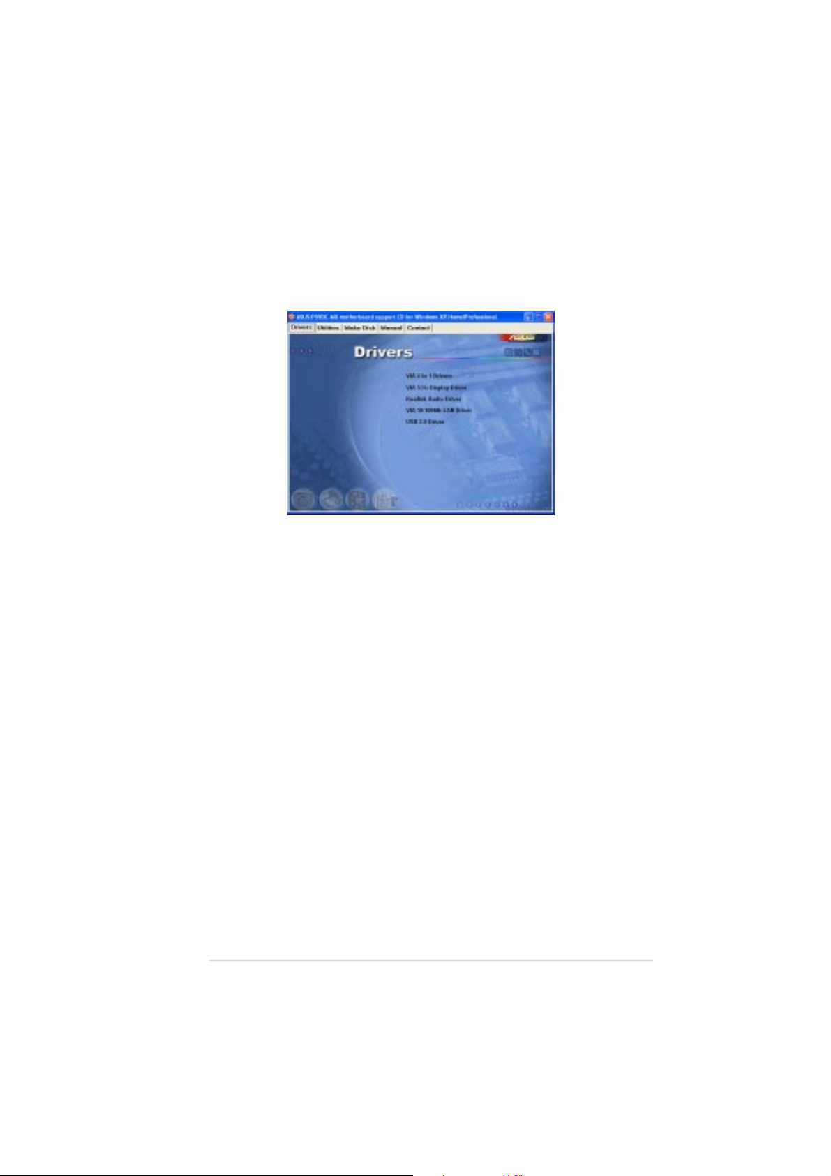
3.2.23.2.2
3.2.2
3.2.23.2.2
The drivers menu shows the available device drivers if the system detects
installed devices. Install the necessary drivers to activate the devices.
VIA VT8251 Chipset DriverVIA VT8251 Chipset Driver
VIA VT8251 Chipset Driver
VIA VT8251 Chipset DriverVIA VT8251 Chipset Driver
Install the VIA VT8251 Chipset Driver.
VIA/S3G Display DriverVIA/S3G Display Driver
VIA/S3G Display Driver
VIA/S3G Display DriverVIA/S3G Display Driver
Install the VIA/S3G UniChrome Family Display Driver.
Realtek Audio DriverRealtek Audio Driver
Realtek Audio Driver
Realtek Audio DriverRealtek Audio Driver
Executes the wizard to install the Realtek ALC653 Audio Driver.
Drivers menuDrivers menu
Drivers menu
Drivers menuDrivers menu
VIA 10/100Mb LAN DriverVIA 10/100Mb LAN Driver
VIA 10/100Mb LAN Driver
VIA 10/100Mb LAN DriverVIA 10/100Mb LAN Driver
Install the VIA Ethernet Driver.
USB 2.0 DriverUSB 2.0 Driver
USB 2.0 Driver
USB 2.0 DriverUSB 2.0 Driver
Installs the USB 2.0 driver.
ASUS P5VDC-MXASUS P5VDC-MX
ASUS P5VDC-MX
ASUS P5VDC-MXASUS P5VDC-MX
3-33-3
3-3
3-33-3
Page 86

3.2.33.2.3
3.2.3
3.2.33.2.3
The Utilities menu shows the applications and other software that the
motherboard supports.
ASUS PC Probe IIASUS PC Probe II
ASUS PC Probe II
ASUS PC Probe IIASUS PC Probe II
This smart utility monitors the fan speed, CPU temperature, and system
voltages, and alerts you of any detected problems. This utility helps you
keep your computer in healthy operating condition.
Utilities menuUtilities menu
Utilities menu
Utilities menuUtilities menu
This utility only support 2000/XP/XP 64bit/2003 server 64bit.
ASUS UpdateASUS Update
ASUS Update
ASUS UpdateASUS Update
The ASUS Update utility allows you to update the motherboard BIOS in a
Windows® environment. This utility requires an Internet connection either
through a network or an Internet Service Provider (ISP). See page 2-8 for
details.
ASUS Screen SaverASUS Screen Saver
ASUS Screen Saver
ASUS Screen SaverASUS Screen Saver
Installs the ASUS screen saver.
ADOBE Reader V7.0ADOBE Reader V7.0
ADOBE Reader V7.0
ADOBE Reader V7.0ADOBE Reader V7.0
Installs the Adobe® Acrobat® Reader V7.0.
Microsoft DirectX 9.0cMicrosoft DirectX 9.0c
Microsoft DirectX 9.0c
Microsoft DirectX 9.0cMicrosoft DirectX 9.0c
Installs the Microsoft® DirectX 9.0c driver.
Anti-Virus UtilityAnti-Virus Utility
Anti-Virus Utility
Anti-Virus UtilityAnti-Virus Utility
Installs the anti-virus program. View the online help for detailed
information.
3-43-4
3-4
3-43-4
Chapter 3: Software supportChapter 3: Software support
Chapter 3: Software support
Chapter 3: Software supportChapter 3: Software support
Page 87

3.2.43.2.4
3.2.4
3.2.43.2.4
The Make Disk menu allows you to make a RAID driver disk.
Make VIA SATA Driver DiskMake VIA SATA Driver Disk
Make VIA SATA Driver Disk
Make VIA SATA Driver DiskMake VIA SATA Driver Disk
Allows you to create a VIA VT8251 32/64bit RAID driver disk.
Make Disk menuMake Disk menu
Make Disk menu
Make Disk menuMake Disk menu
3.2.53.2.5
3.2.5
3.2.53.2.5
The Manuals menu contains a list of supplementary user manuals. Click an
item to open the folder of the user manual.
Intel LGA775 CPU Install User’s ManualIntel LGA775 CPU Install User’s Manual
Intel LGA775 CPU Install User’s Manual
Intel LGA775 CPU Install User’s ManualIntel LGA775 CPU Install User’s Manual
Allows you to open the Intel® LGA775 CPU installation guide.
ASUS P5VDC-MXASUS P5VDC-MX
ASUS P5VDC-MX
ASUS P5VDC-MXASUS P5VDC-MX
Manuals menuManuals menu
Manuals menu
Manuals menuManuals menu
Most user manual files are in Portable Document Format (PDF). Install
the Adobe® Acrobat® Reader from the
a user manual file.
Utilities menuUtilities menu
Utilities menu before opening
Utilities menuUtilities menu
3-53-5
3-5
3-53-5
Page 88

3.2.63.2.6
3.2.6
3.2.63.2.6
Click the
also find this information on the inside front cover of this user guide.
ASUS Contact informationASUS Contact information
ASUS Contact information
ASUS Contact informationASUS Contact information
Contact Contact
Contact tab to display the ASUS contact information. You can
Contact Contact
3-63-6
3-6
3-63-6
Chapter 3: Software supportChapter 3: Software support
Chapter 3: Software support
Chapter 3: Software supportChapter 3: Software support
Page 89

3.3 RAID configurations
The motherboard supports the following RAID configurations.
RAID 0RAID 0
RAID 0
RAID 0RAID 0
write data in parallel, interleaved stacks. Two hard disks perform the same
work as a single drive but at a sustained data transfer rate, double that of
a single disk alone, thus improving data access and storage. Use of two
new identical hard disk drives is required for this setup.
RAID 1RAID 1
RAID 1
RAID 1RAID 1
from one drive to a second drive. If one drive fails, the disk array
management software directs all applications to the surviving drive as it
contains a complete copy of the data in the other drive. This RAID
configuration provides data protection and increases fault tolerance to the
entire system. Use two new drives or use an existing drive and a new drive
for this setup. The new drive must be of the same size or larger than the
existing drive.
RAID 0+1RAID 0+1
RAID 0+1 is
RAID 0+1RAID 0+1
(redundancy data) having to be calculated and written. With the RAID 0+1
configuration you get all the benefits of both RAID 0 and RAID 1
configurations. Use four new hard disk drives or use an existing drive and
three new drives for this setup.
JBODJBOD
JBOD
JBODJBOD
disk drives that are not yet configured as a RAID set. This configuration
stores the same data redundantly on multiple disks that appear as a single
disk on the operating system. Spanning does not deliver any advantage
over using separate disks independently and does not provide fault
tolerance or other RAID performance benefits.
(Data striping)
(Data mirroring)
data striping
(Spanning)
stands for
optimizes two identical hard disk drives to read and
copies and maintains an identical image of data
and
data mirroring
Just a Bunch of DisksJust a Bunch of Disks
Just a Bunch of Disks and refers to hard
Just a Bunch of DisksJust a Bunch of Disks
combined without parity
ASUS P5VDC-MXASUS P5VDC-MX
ASUS P5VDC-MX
ASUS P5VDC-MXASUS P5VDC-MX
3-73-7
3-7
3-73-7
Page 90

If you want to boot the system from a hard disk drive included in a RAID
set, copy first the RAID driver from the support CD to a floppy disk
before you install an operating system to a selected hard disk drive.
Refer to section “3.4 Creating a RAID driver disk” for details.
3.3.13.3.1
3.3.1
3.3.13.3.1
The motherboard supports RAID function on Serial ATA hard disk drives.
For optimal performance, install identical drives of the same model and
capacity when creating a disk array.
Installing Serial ATA (SATA) hard disksInstalling Serial ATA (SATA) hard disks
Installing Serial ATA (SATA) hard disks
Installing Serial ATA (SATA) hard disksInstalling Serial ATA (SATA) hard disks
To install the SATA hard disks for a RAID configuration:
1. Install the SATA hard disks into the drive bays.
2. Connect the SATA signal cables.
3. Connect a SATA power cable to the power connector on each drive.
Entering VIA Tech RAID BIOS UtilityEntering VIA Tech RAID BIOS Utility
Entering VIA Tech RAID BIOS Utility
Entering VIA Tech RAID BIOS UtilityEntering VIA Tech RAID BIOS Utility
1. Boot-up your computer.
2. During POST, press <Tab> to enter VIA RAID configuration utility.
Installing hard disksInstalling hard disks
Installing hard disks
Installing hard disksInstalling hard disks
Refer to the RAID controllers user manual in the motherboard support
CD for detailed information on RAID configurations. See section “3.2.4
Manuals menu”.
The following menu options will appear.
The RAID BIOS information on the setup screen shown below is for
reference only. What you see on your screen may not exactly match
what is shown here.
3-83-8
3-8
3-83-8
Chapter 3: Software supportChapter 3: Software support
Chapter 3: Software support
Chapter 3: Software supportChapter 3: Software support
Page 91

Create ArrayCreate Array
Create Array
Create ArrayCreate Array
From the VIA RAID BIOS utility main menu, select
<Enter><Enter>
press
<Enter>. The main menu items on the upper-left corner of the
<Enter><Enter>
Create ArrayCreate Array
Create Array then
Create ArrayCreate Array
screen are replaced with create array menu options.
VIA Tech. VT8251 Series SATA RAID BIOS Ver 1.xx
Auto Setup For Data Security
Array Mode RAID 1 (Mirroring)
Select Disk Drives
Start Create Process
Channel Drive Name Array Name Mode Size(GB) Status
Serial_Ch0 Master XXXXXXXXXXX ARRAY 0 SATA 999.99 XXXXXXX
Serial_Ch1 Master XXXXXXXXXXX ARRAY 0 SATA 999.99 XXXXXXX
RAID 0 for performanceRAID 0 for performance
RAID 0 for performance
RAID 0 for performanceRAID 0 for performance
1. From the create array menu, select
Create a RAID array with
the hard disks attached to
VIA RAID controller
F1 : View Array/Disk Status
↑↑
↓↓
↑
,
↓
: Move to next item
↑↑
↓↓
Enter : Confirm the selection
ESC : Exit
Array ModeArray Mode
Array Mode, then press
Array ModeArray Mode
<Enter>. The supported RAID configurations appear on a pop-up
menu.
RAID 0 for performance
RAID 1 for data protection
RAID SPAN for capacity
2. Select
RAID 0 for performanceRAID 0 for performance
RAID 0 for performance then press <Enter>.
RAID 0 for performanceRAID 0 for performance
From this point, you may choose to auto-configure the RAID array by
selecting
Auto Setup for PerformanceAuto Setup for Performance
Auto Setup for Performance or manually configure the
Auto Setup for PerformanceAuto Setup for Performance
RAID array for stripped sets. If you want to auto-configure, proceed
to the next step, otherwise, skip to step 5.
3. Select
Auto Setup for PerformanceAuto Setup for Performance
Auto Setup for Performance and press <Enter>. The
Auto Setup for PerformanceAuto Setup for Performance
following confirmation message appears.
ASUS P5VDC-MXASUS P5VDC-MX
ASUS P5VDC-MX
ASUS P5VDC-MXASUS P5VDC-MX
Auto create array will destroy all
data on disks, Continue? (Y/N)
3-93-9
3-9
3-93-9
Page 92

4. Press <Y> to confirm or <N> to return to the configuration options. If
you selected <Y>, proceed to step 9.
5. Select
Select Disk DrivesSelect Disk Drives
Select Disk Drives, then press <Enter>. Use arrow keys to
Select Disk DrivesSelect Disk Drives
select disk drive, then press <Enter> to mark selected drive. An
asterisk appears before a selected drive.
6. Select
Block SizeBlock Size
Block Size, then press <Enter> to set array block size. A list
Block SizeBlock Size
of valid array block sizes are displayed on a pop-up menu.
TIP: TIP:
TIP: For server systems, use of a lower array
4K
8K
16K
32K
64K
TIP: TIP:
block size is recommended. For multimedia
computer systems used mainly for audio and
video editing, a higher array block size is
recommended for optimum performance.
Use arrow keys to move selection bar on items and press <Enter> to
select.
7. Select
Start Create ProcessStart Create Process
Start Create Process and press <Enter> to set up hard disk
Start Create ProcessStart Create Process
for RAID system. The following confirmation message appears:
The data on the selected disks will
be destroyed. Continue? (Y/N)
8. Press <Y> to confirm or <N> to return to the configuration options.
9. Press <Esc> to go back to main menu.
RAID 1 for data protectionRAID 1 for data protection
RAID 1 for data protection
RAID 1 for data protectionRAID 1 for data protection
1. From the create array menu, select
The supported RAID configurations appear on a pop-up menu.
RAID 0 for performance
RAID 1 for data protection
RAID 1 for data protection
RAID 0/1
RAID SPAN for capacity
2. Select
3-103-10
3-10
3-103-10
RAID 1 for data protectionRAID 1 for data protection
RAID 1 for data protection then press <Enter>.
RAID 1 for data protectionRAID 1 for data protection
Array ModeArray Mode
Array Mode, then press <Enter>.
Array ModeArray Mode
Chapter 3: Software supportChapter 3: Software support
Chapter 3: Software support
Chapter 3: Software supportChapter 3: Software support
Page 93

3. From this point, you can auto-configure the RAID array by selecting
Auto Setup for Data SecurityAuto Setup for Data Security
Auto Setup for Data Security or manually configure the RAID
Auto Setup for Data SecurityAuto Setup for Data Security
array for mirrored sets. If you want to auto-configure, proceed to the
next step, otherwise, skip to step 6.
4. Select
Auto Setup for Data SecurityAuto Setup for Data Security
Auto Setup for Data Security and press <Enter>. The
Auto Setup for Data SecurityAuto Setup for Data Security
following confirmation message appears.
Auto create array will destroy all
data on disks, Continue? (Y/N)
5. Press <Y> to confirm or <N> to return to the configuration options. If
you selected <Y>, proceed to step 11.
6. Select
Select Disk DrivesSelect Disk Drives
Select Disk Drives, then press <Enter>. Use arrow keys to
Select Disk DrivesSelect Disk Drives
select disk drive/s, then press <Enter>. An asterisk appears before a
selected drive.
7. Select
Start Create ProcessStart Create Process
Start Create Process and press <Enter> to setup hard disk
Start Create ProcessStart Create Process
for RAID system. The following inquiry appears:
Save the data on source disk to
mirror after creation? (Y/N)
8. If you select <Y> the utility will duplicate your data. Press <Y>
anytime if you want to exit the duplication process.
Duplicating...
RAID 1 for data protection
Press Yes(Y) to Escape
9. If you select <N>, the following confirmation message appears.
The data on the selected disks will
be destroyed. Continue? (Y/N)
10. Press <Y> to confirm or <N> to return to the configuration options.
11. Press <Esc> to go back to main menu.
ASUS P5VDC-MXASUS P5VDC-MX
ASUS P5VDC-MX
ASUS P5VDC-MXASUS P5VDC-MX
3-113-11
3-11
3-113-11
Page 94

3.4 Creating a RAID driver disk
A floppy disk with the RAID driver is required when installing Windows
2000/XP or later operating system on a hard disk drive that is included in a
RAID set.
To create a RAID driver disk:
1. Place the motherboard support CD into the CD-ROM drive.
2. When the
64bit RAID Driver Disk64bit RAID Driver Disk
64bit RAID Driver Disk to create a VIA RAID driver disk
64bit RAID Driver Disk64bit RAID Driver Disk
Drivers Drivers
Drivers menu appears, click
Drivers Drivers
Make VIA VT8251 32/Make VIA VT8251 32/
Make VIA VT8251 32/
Make VIA VT8251 32/Make VIA VT8251 32/
Or
Browse the contents of the support CD to locate the driver disk utility
and go to
\Drivers\Chipset\EIA 4 in 1\Disk\Drivers\Chipset\EIA 4 in 1\Disk
\Drivers\Chipset\EIA 4 in 1\Disk for the VIA RAID
\Drivers\Chipset\EIA 4 in 1\Disk\Drivers\Chipset\EIA 4 in 1\Disk
driver disk utility
Refer to section “3.2.2 Drivers menu” for details.
3 Insert floppy disk to floppy disk drive.
4. Follow succeeding screen information to complete process.
5. Write-protect the floppy disk to avoid computer virus infection.
To install the RAID driver:
1. During the OS installation, the system prompts you to press the F6
key to install third-party SCSI or RAID driver.
2. Press <F6>
then insert the floppy disk with RAID driver into the floppy
disk drive.
3. Follow the succeeding screen instructions to complete the installation.
®
3-123-12
3-12
3-123-12
Chapter 3: Software supportChapter 3: Software support
Chapter 3: Software support
Chapter 3: Software supportChapter 3: Software support
 Loading...