

Page 1

P
4
V
T
C
V
T
T
C
C
P
P
4
4
V
FCC Information and Copyright
This equipment has been tested and found to comply with the limits of a
Class B digital device, pursuant to Part 15 of the FCC Rules. These limits
are designed to provide reasonable protection against harmful
interference in a resi denti al i nst all ati on. Thi s equi pment generat es, uses
and can radiate radi o fr equency energ y and, i f not inst all ed and used i n
accordance with the instructions, may cause harmful interference to radio
communications. There is no guarantee that interference will not occur in
a partic ular in st alla tion.
The vendor makes no representations or warranties with respect to the
contents here of and specially disclaims any implied
merchantability or fitness for any p urpose. Further the vendor res erves
the right to revise this publication and to make changes to the contents
here of without obligation to notify any party beforehand.
Duplication of this publication, in part or in whole, is not allowed without
first obtaining the vendor’s approval in writing.
The content of this user’s man ual is subje ct to be changed without not ice
and we will not be responsible for any mistakes found in this user’s
manual. All the brand and product names are trademarks of their
respective companies.
warranties of
i
Page 2

C
o
n
t
e
n
t
C
C
o
o
n
t
e
n
t
n
t
e
n
t
LAYOUT OF P4VTC .................. .................. ... .................. ... ....................1
COMPONENT INDEX.................. ... .................. ... ...................................2
ENGLISH...................................................................................................3
P4VTC Features ......................................................................................................... 3
Package contents......................................................................................................4
How to setup Jumper ................................................................................................ 5
CPU Installation ......................................................................................................... 5
DDR DIMM Modules: DIMM1/ DIMM2........................................................................ 6
Jumpers, Headers, Con ne ctors & Slots................. .. .............. .. .. .............. .. .............. 7
WARPSPEEDER.....................................................................................14
Introduction.............................................................................................................. 14
System Requirement............. .. .............. .. .. .............. .. .............. .. .. .............. .. ... ......... 14
Installation................................................................................................................ 15
Usage........................................................................................................................ 16
STUDIOFUN!
Introduction.............................................................................................................. 24
Hardware Requiremen ts................. .. .............. .. .............. .. .............. .. .. .............. .. ..... 24
Installation and Usage............................................................................................. 24
TM
(OPTIONAL) .............................................................24
TROUBLE SHOOTING.........................................................................25
ii
Page 3
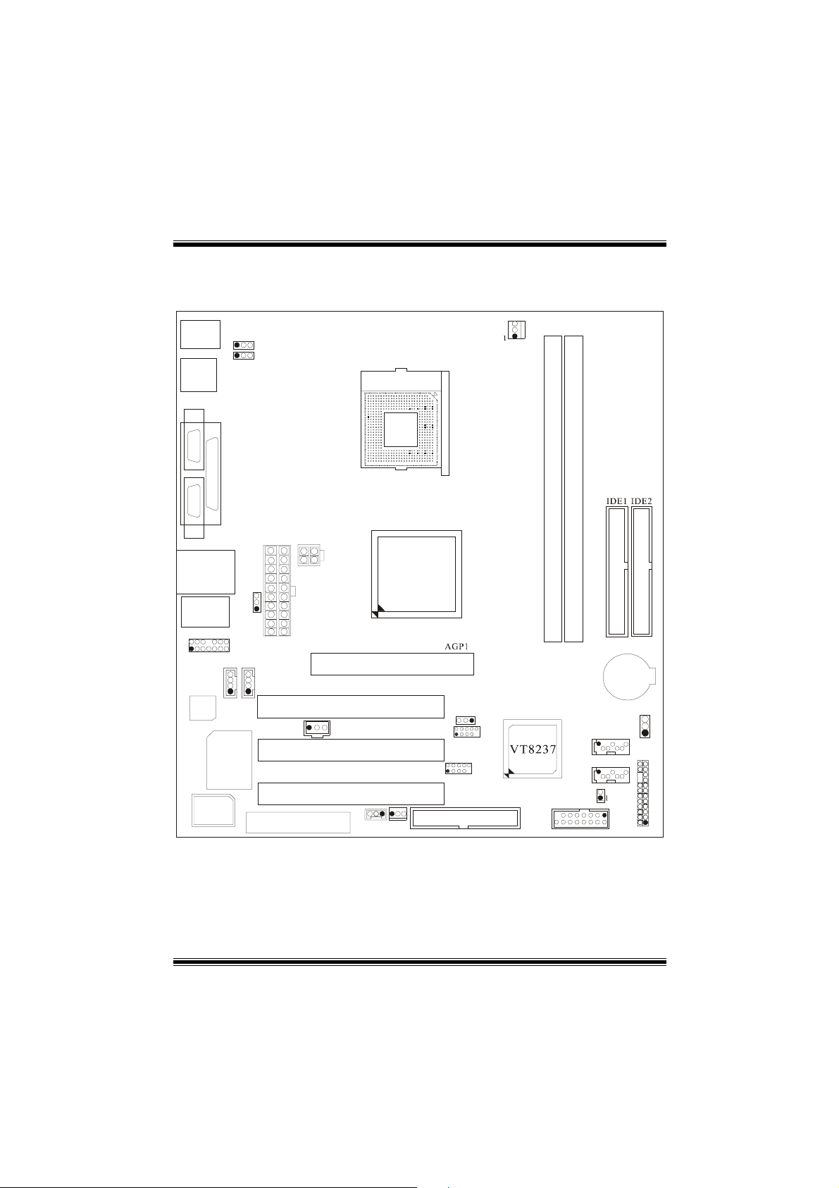
Layout of P4VTC
JKBMS1
Mouse &
Keyboard
JUSB1
USB
JCOM1
COM1COM2
Parallel Port
JCOM2
JUSBLAN1
JAUDIO
2
1
JAUDIO1
JCDIN1
CODEC
ITE I/O
BIOS
※
JKBV1
1
1
JUSBV1
Socket 478
JPRNT1
JATXPWR2
PT800
1
JUSBV2
14
JATXPWR1
13
JCDIN2
1
1
1
CNR1
CNR SLOT
NOTE: ●represents the first pin.
AGP SLOT
PCI SLOT
JSPDIF1
PCI SLOT
PCI SLOT
JWOL1
1
1
JSFAN1
PU
CPU1
PCI1
JUSBV3
PCI2
PCI3
1
JUSB3
2
1 9
JUSB4
FLOPPY DISK CONN.
JCFAN1
DIMM1
DIMM2
PRIMARY IDE CONN.
SECONDARY IDE CONN.
BAT1
1
102
9
10
FDD1
JC1
JGAME1
JCMOS1
JSATA2
17
24
JSATA1
17
115
216
JPANEL1
1
23
12
1
Page 4
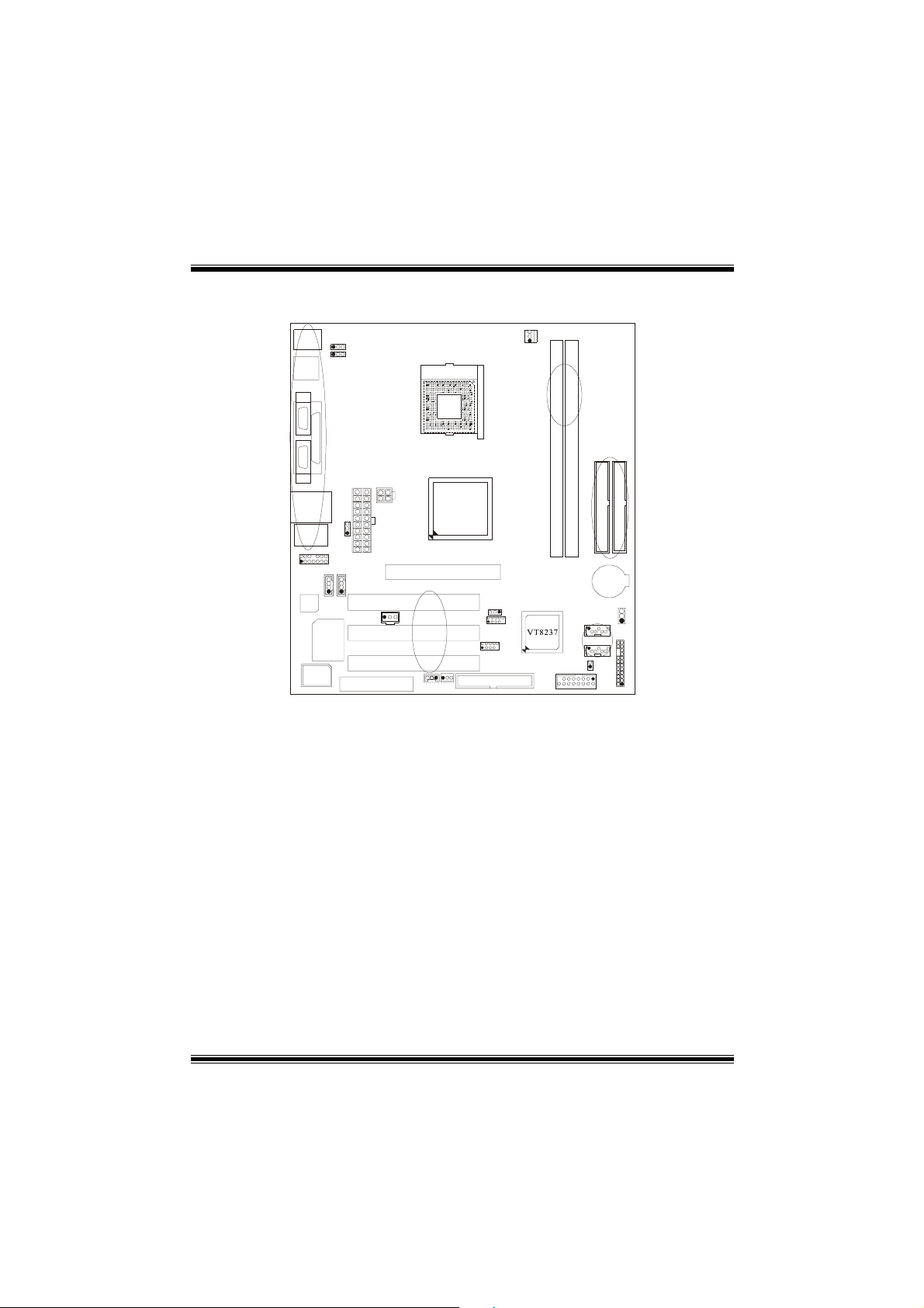
Component Index
U
A
B
Socket 478
P
A1
Z
C
Y
F
DE
PT800
A. Power Source Selection for Keyboard N. Wake On LAN Header (JWOL1)
and Mouse (JKBV1) O. System FAN Header (JSFAN1)
B. Power Source Sele ction for USB P. Floppy Disk Conne ctor (FDD1)
(JUSBV1) Q. Game Port Header (JGAME1)
C. Back Panel Connector R. Front Panel Connector (JPANEL1)
D. ATX Power Connector (JATXPWR2) S. Case Open Connector (JC1)
E. ATX Power Connector (JATXPWR1) T. Serial ATA Connector (JSATA1-2)
F. Power Source Selection for USB U. Clear CMOS (JCMOS1)
(JUSBV2) V. Front USB Header (JUSB4)
G. Front Audio Header (JAUDIO1) W. Front USB Header (JUSB3)
H. Accelerated Graphic Port Slot (AGP1) X. Power Source Selection for USB
I. CD-ROM Audio-In Header (JCDIN2) (JUSBV3)
J. CD-ROM Audio-In Header (JCDIN1) Y. IDE Connectors (IDE1-2)
K. PCI BUS Slots (PCI 1-3) Z. DIMM Modules (DIMM1-2)
L. Digital Audio Connector (JSPDIF1) A1 CPU Fan Connector (JCFA N 1)
M. Communication Network Riser Slot
(CNR1)
CODEC
BIOS
ITE I/O
G
IJ
K
L
M
N
O
H
BAT1
X
W
V
P
T
R
S
Q
2
Page 5

English
P4VTC Features
A. Hardware
CPU
Provides Socket 478.
Supports the Intel® processor.
Supports Hyper-Threading Technology.
Front Side Bus at 400/533/800 MHz.
Chipset
North Bridge: VIA PT800.
South Bridge: VIA VT8237.
Main Memory
Supports up to 2 DDR devices.
Supports 200/266/333/400 MHz DDR devices.
Maximum memory size of 2GB.
Super I/O
Chip: ITE IT8705.
Slots
Three 32-bit PCI bus master slots.
One AGP slot.
One CNR slot.
On Board IDE
Suppor ts four IDE disk drives.
Supports PIO Mode 4, Bride Mode and Ultra DMA 33/66/100/133 Bus Master
Mode.
LAN
Chip: VIA VT6103.
Suppor ts 10 Mb /s and 100 Mb/s auto-negotiation
Half/ Full duplex capability.
On Board AC’97 Sound Codec
Chip: CMI9739A.
Compliant with AC’97 specification.
AC99 2.2 interface.
Supports 6 channels.
3
Page 6
On Board Peripherals
a. Rear side
2 serial ports.
1 parallel port. (SPP/EPP/ECP mode)
Audio ports in vertical position.
1 LAN jack.
PS/2 mouse and PS/2 keyboard.
4 USB2.0 ports.
b. Front Side
1 floppy port supports 2 FDDs with 360K, 720K, 1.2M, 1.44M and 2.88Mbytes.
4 USB2.0 ports
1 front audio header.
Dimensions
ATX Form Factor: 24.5 X 22.5cm (W X L)
B. BIOS & Software
BIOS
Award legal Bios.
APM1.2.
ACPI.
USB Function.
Software
Supports WarpspeederTM, 9th TouchTM, FLASHER™, WinFlasher
(optional).
Offers the highest p erformance for Windows 98 SE, Windows 2000, Windows Me,
Windows XP, SCO UNIX etc.
TM
and StudioFun!
Package contents
HDD Cable X1
FDD Cab l e X1
User’s Manual X1
USB Cable X1 (optional)
Rear I/O Panel for Micro ATX Case X1 (optional)
Fully Setup Driver CD X1
StudioFun! Application CD X1 (optional)
S/PDIF Cable X 1(optional)
4
Page 7
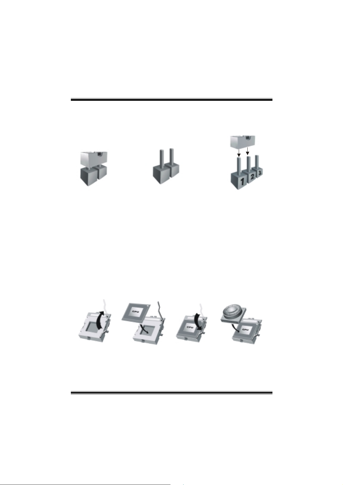
How to setup Jumper
The illustrati on shows how j umper s are set up. When the Jum per cap is place d on pin s, the
jumper is “close”. If no jumper cap is placed on the pins, the jumper is ”open”. The
illustration shows a 3-pin jumper whose pin 1and 2 are “close” when jumper cap is placed
on these 2 pins.
Jumper close Jumper open Pin 1-2 close
CPU Inst a l l ation
Step1:
Step2: Look for the whit e do t/cut edge. The white dot/cut edge should point towards the
Step3:
Step4: Put the CPU fan on the CPU and buckle it. Connect the CPU fan power cable to
Pull the lever sideways away from the socket and then raise the lever up to a
90-degree angle.
lever pivot. The CPU will fit only in the correct orientation.
Hold the CPU down firmly, and then close the leve r.
the JCFAN1. This completes the installation.
Step1 Step2 Step3 Step4
5
Page 8
CPU Fan Header: JCFAN1
3
1
JCFAN1
Pin No. Assign ment
1
2
3
Ground
+12V
FAN rpm rate Sense
System Fan Head e r: JS F A N1
31
JSFAN1
Pin No. Assign ment
1
2
3
FAN rpm rate Sense
Ground
+12V
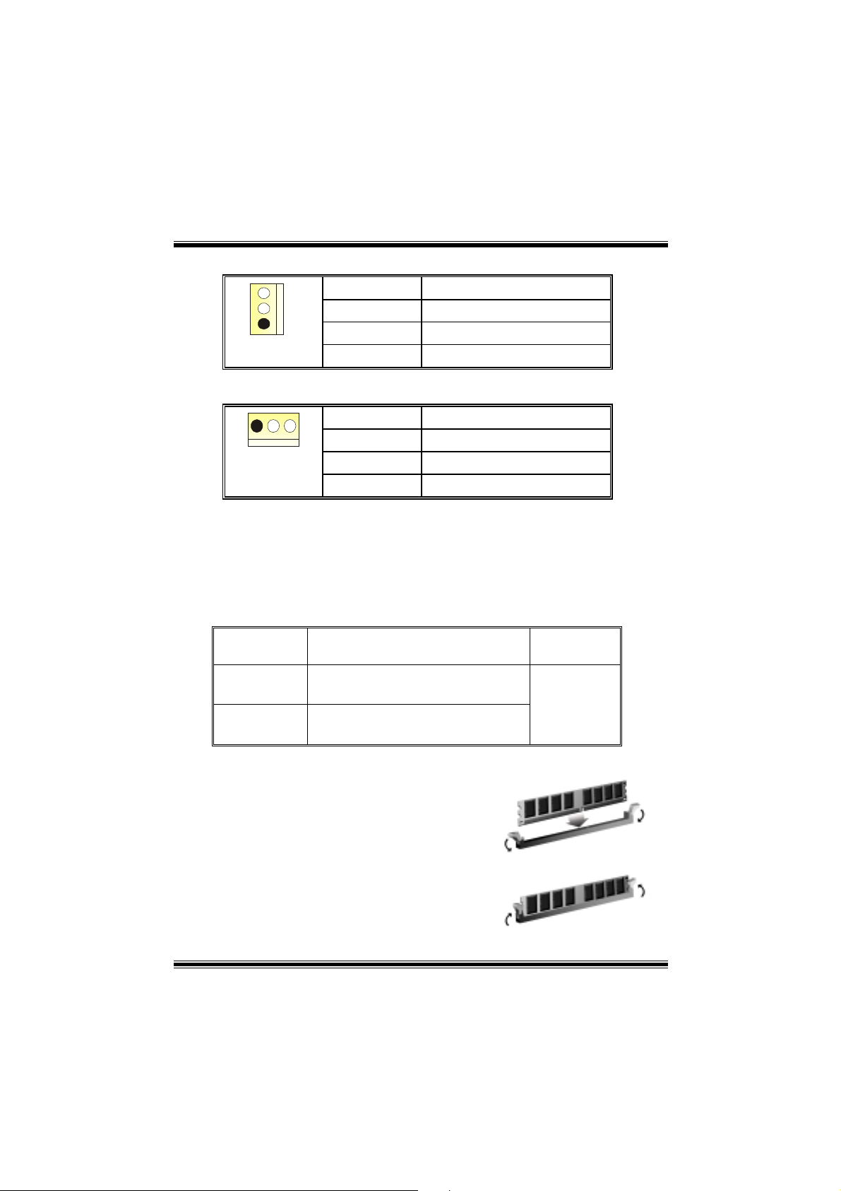
DDR DIMM Modules: DIMM1/ DIMM2
DRAM Access Time: 2.5V Unbuffered DDR 200/266/333/400 MHz Type required.
DRAM Type: 64MB/ 128MB/ 256MB/ 512MB/ 1GB D IMM Module (184 p in)
Total Memory Size with Unbuffered DIMMs
DIMM Socket
Location
DIMMB1 64MB/128MB/256MB/512MB/1GB
DIMMB2 64MB/128MB/256MB/512MB/1GB
Installing DDR Module
1. Unlock a DIMM slot by pr es sin g th e retaining
clips outward. Align a DIMM on the slot such
that the notch on the DIMM matches the
break on the slot.
2. Insert the DIMM firmly and vertically into the
slot until the retaining chip snap back in
place and the Dimm is properly seated.
DDR Module Total Mem or y
Size (MB)
*1
*1
***Only for re f e rence* **
Max is
2 GB
6
Page 9

Jumpers, Headers, Connectors & Slots
Floppy Disk Connector: FDD1
The motherboard provides a standard floppy disk connector that supports 360K,
720K, 1.2M, 1.44M and 2.88M floppy disk types. This connector supports the
provided floppy drive ribbon cables.
Hard Disk Connectors: IDE1/ IDE2
The motherboard has a 32-bit Enhanced PCI IDE Controller that provides PIO
Mode 0~4, Bus Master, and Ultra DMA 33/ 66/ 100/ 133 functionality. It has two
HDD connectors IDE1 (primary) and IDE2 (secondary).
The IDE connectors can connect a master and a slave drive, so you can connect
up to four hard disk drives. The first hard drive should always be connected to
IDE1.
Peripheral Component Interconnect Slots: PCI 1-3
This motherboard is equipped with 3 standard PCI slots. PCI stands for Peripheral
Component Interconnect, and it is a bus standard for expansion cards. This PCI
slot is designated as 32 bits.
Accelerated Graphics Port Slot: AGP1
Your monitor will attach directly to that video card. This motherboard supports
video cards for PCI slots, but it is also equipped with an Accelerated Graphics Port
(AGP). An AGP card will take advantage of AGP technology for improved video
efficiency and performance, especially with 3D graphics.
Communication Network Riser Slot: CNR1
The CNR specification is an open Industry Standard Architecture, and it defines a
hardware scalabl e ri ser card interface, which supports m odem only.
Serial ATA Connector: JSATA1/ JSATA2
The motherboard has a PCI to SATA Controller with 2 channels SATA interface, it
satisfies the SATA 1.0 spec and with transfer rate at 1.5Gb/s.
7
Page 10

RST
2
4
6
8
10
12
14
16
18
20
22
24
IRON/OFF
24
23
IR
Sleep Control
Ground
NA NA
Power LED (+)
Power LED (+)
Power LED (-)
Power But t o n
Ground
KEY
KEY
Ground
IRRX
Sleep
Button
POWER
LED
Power-on
Button
IrDA
Connector
Front Panel Connector: JPANEL1
SLP
JPANEL1
Pin Assignment Function Pin Assignment Function
1
3
5
7
9
HDD LED (+)
11
HDD LED (-)
13
15
Reset Con trol
17
19
21
23
2
1
+5V
NA
NA
Speaker
Ground
NA
NA
+5V
IRTX
PWR_LED
(+) (-)(+)
SPK
Speaker
Connector
Hard Drive
LED
Reset
Button
IrDA
Connector
(+) (-)
HLED
Front USB Header: JUSB3/ JUSB4
2
1
JUSB3/4
Pin Assignment Pin Assignment
10
1
3
9
5
7
9
+5V(fused)
USBP4-
USBP4+
Ground
KEY
2
4
6
8
10
+5V(fused)
USBP5-
USBP5+
Ground
NA
Wake On LAN Header: JWOL1
13
JWOL1
Pin Assignment
1
2
3
+5V Standby
Ground
Wake up
8
Page 11

Power Connectors: JATXPWR1/ JATXPWR2
PIN Assignment PIN Assignment
1 +3.3V 11 +3.3V
2 +3.3V 12 -12V
3 Ground 13 Ground
4 +5V 14 PS_ON
5 Ground 15 Ground
6 +5V 16 Ground
7 Ground 17 Ground
8 PW_OK 18 -5V
9 Standby Voltage
+5V
10 +12V 20 +5V
PIN Assignment PIN Assignment
1
+12V
10
1
JATXPWR1
4
2
20
11
3
19 +5V
3
Ground
JATXPWR2
2
+12V
4
Ground
Power Source Selection for Keyboard and Mouse: JKBV1
JKBV1
Assignment
Description
1 3
Pin 1-2 close
1 3
Pin 2-3 close
+5V
+5V Standby
Voltage
+5V for keyboard and mouse
PS/2 Mouse and PS/2 Keyboard are
powered with +5V standby voltage
Note: In order to support this function “Power-on the system via keyboard
and mouse, “JKBV1” jumper cap should be placed on pin 2-3.
9
Page 12

Power Source Selection for USB: JUSBV1/ JUSBV2/ JUSBV3
JUSBV1/JUSBV2/
JUSBV3
Assignment Description
1 3
Pin 1-2 close
1 3
Pin 2-3 close
+5V
+5V Standby
Voltage
JUSBV1: 5V for USB located at the
JUSB1 connector port
JUSBV2: 5V for USB located at the
JUSBLAN1 port
JUSBV3: 5V for USB located at the
JUSB3/4 ports
JUSBV1: JUSB1 port powered with
standby voltage of 5V
JUSBV2: JUSBLAN1 port powered with
standby voltage of 5V
JUSBV3: JUSB3/4 ports powered with
standby voltage of 5V
Note: In order to support this function “Power-on the system via USB device”,
“JUSBV1/JUSBV2/JUSBV3” jumper cap should be placed on pin 2-3
respectively.
Clear CMOS Jumper: JCMOS1
JCMOS1 Assignment
3
1
Pin 1-2 Close
3
1
Pin 2-3 Close
Normal Operation (default)
Clear CMOS Data
The following procedure s are for reset ting the
BIOS password. It is important to follow these
instructions closely.
10
Page 13

※ Clear CMOS Procedures:
1. Remove AC power line.
2. Set the jumper to “Pin 2-3 close”.
3. Wait for five seconds.
4. Set the jumper to “Pin 1-2 close”.
5. Power on AC.
6. Reset your desired password or clear the CMOS data.
Case Open Connector: JC1
Pin
Assignment
1
JC1
1
2
Case Open Signal
Ground
CD-ROM Audio-In Header: JCDIN1/ JCDIN2
4
1
JCDIN1/ 2
Front Panel Audio Header: JAUDIO1
2
2
1
1
Pin Assignment Pin Assignment
1
3
5
7
9
11
13
Mic In/ Center
Mic Power/ Bass
Right Line Out/ Right
Speaker Out
Reserved
Left Line Out/ Left
Speaker Out
Right Line In/ Right Rear
Speaker
Left Line In/ Left Rear
Speaker
Pin Assignment
1
2
3
4
Left Channel Input
Ground
Ground
Right Channel Input
14
14
13
13
JAUDIO1
2
4
6
8
10
12
Right Line In/ Right Rear
14
Ground
Audio Power
Right Line Out/ Right
Speaker Out
Left Line Out/ Left
Speaker Out
Speaker
Left Line In/ Left Rear
Speaker
Key
11
Page 14

Front Panel Audio Header: JAUDIO1 (optional)
2
121
Pin Assignment Pin Assignment
1
3
5
7
9
11
13
15
Mic In
Mic Power
Right Line Out/ Right
Speaker Out
Reserved
Left Line Out/ Left
Speaker Out
Surrender Right
Center
Ground
16
15
JAUDIO1
2
4
6
8
10
12
14
16
Right Line Out/ Right
Ground
Audio Power
Speaker Out
Key
Left Line Out/ Left
Speaker Out
Surrender Left
Subwoof
Key
Digital Audio Connector: JSPDIF1
13
JSPDIF1
Pin Assignment
1
2
3
+5V
SPDIF_OUT
Ground
Game Port Header: JGAME1
15
Pin Assignment Pin Assignment
1
3
5
7
9
11
13
15
Joystick B Coordin ate X
Joystick B Coordin ate Y
+5V
Joystick B Button 1
MIDI Output
Joystick B Button 2
MIDI Input
NA
1
216
JGAME1
10
12
14
16
12
2
4
6
8
Joystick A Button 1
Joystick A Coordi nate X
Joystick A Coordi nate Y
Joystick A Button 2
+5V
Ground
Ground
+5V
Page 15

Serial ATA Connector: JSATA1/ JSATA2
741
JSATA1/ JSATA2
Pin Assignment Pin Assignment
1
3
5
7
Ground
TXRX-
Ground
Back Panel Connectors
JKBMS1
PS/2
Mouse
JPRNT1
Parallel
JUSB1
JUSBLAN1
2
4
6
TX+
Ground
RX+
Line In
Speaker Out
MIC I n
PS/2
Keyboard
USB
COM1
JCOM1
6 Channel Speakers
Speaker Out
COM2
JCOM2
Line In/ Rear Speaker
Mic In/ Center & Bass
13
USB
JAUDIO
Page 16

WarpSpeeder
Introduction
[ WarpSpeeder™ ], a new powerful control utility, features three user-friendly functions
including Overclock Manager, Overvoltage Manager, and Hardware Monitor.
With the Overcl ock Mana ge r, use r s can ea si ly adjust the fre quency they prefer or they can
get the best CPU performance with just one click. The Overv oltage Manager, on the other
hand, helps to power up CPU core voltage and Memory voltage. The cool Hardware
Monitor smartly indicates the temperatures, voltage and CPU fan speed as well as the
chipset information. Also, in the About panel, you can get detail descriptions about BIOS
model and chipsets. In addition, the frequency status of CPU, memory, AGP and PCI
along with the CPU speed are sy nchronically shown on our main panel.
Moreover, to protect users' computer sy stems if the setting is not appropriate when testing
and results in system fail or hang, [ WarpSpeeder™ ] technology assures the system
stability by automatically rebooting the computer and then restart to a speed that is either
the original system speed or a suitable one.
System Requirement
OS Support: Windows 98 SE, Windows Me, Windows 2000, Windows XP
DirectX: DirectX 8.1 or above. (The Windows XP operating system includes DirectX 8.1. If
you use Windows XP, you do not need to install DirectX 8.1.)
14
Page 17

Installation
1. Execute the setup execution file, and then the following dialog will pop up.
Please click “N ext” button and follow the default procedure to install.
2. When you see the following dialog in setup procedure, it means setup is
completed. If the “Launch the WarpSpeeder Tray Utility” checkbox is checked,
the Tray Icon utility and [WarpSpeeder™] utility will be automatically and
immediately launched after you click “Finish” button.
15
Page 18

Usage
The following figures are just only for reference, the screen printed in this user manual will
change according to your motherboard on hand.
[WarpSpeeder™] includes 1 tray icon and 5 panels:
1. Tray Icon:
Whenever the Tray Icon util i ty is laun ched, it will displ ay a little t ray ico n on th e r igh t side o f
Windows Taskbar.
16
Page 19

This utility is responsible for conveniently invoking [WarpSpeeder™] Utility. You can use
the mouse by clicking the left button in order to invoke [WarpSpeeder™] directly from the
little tray icon or you can right-click the little tray icon to pop up a popup menu as fol lowing
figure. The “Launch Utility” item in the popup menu has the same function as mouse
left-click on tray icon and “Exit” item will cl ose Tray Icon utility if selected.
2. Main Panel
If you click the tray icon, [ WarpSpeeder™ ] utility will be invoked. Please refer
do the following figure; the utility’s first window you will see is Main Panel.
Main Panel contains features as follows:
a. Display the CPU Speed, CPU external clock, Memory clock, AGP clock, and PCI
clock information.
b. Contains About, Voltage, Overclock, and Hardware Monitor Buttons for invoking
respective panels.
c. With a user-friendly Status Animation, it can represent 3 overclock percentage
stages:
Duck walking => overclock percentage from 100% ~ 110 %
Duck running => overclock percentage from 110% ~ 120%
Duck burning => overclock percentage from 120% ~ above
17
Page 20

3. Voltage Panel
Click the Voltage button in Main Panel, the button will be highlighted and the Voltage
Panel will slide out to up as the following figure .
In this panel, you can decide to increase CPU core voltage and Memory voltage or not.
The default setting is “No”. If you want to get the best performance of overclocking, we
recommend you click the option “Yes”.
18
Page 21

4. Overclock Panel
Click the Overclock button in Main Panel, the button will be highlighted and the Overclock
Panel will slide out to left as the following figure.
19
Page 22

Overclock Panel contains t hese features:
a. “–3MHz button” , “-1M Hz button” , “+1 MHz button” , and “+ 3MHz butto n”: provi de u ser
the ability to do real-time overclock adjustment.
Warning: Manually overclock is potentially dangerous, especially when the
overclocking percentage is over 110 %. We strongly recommend you verify
every speed you overclock by click the Verify button. Or, you can just click
Auto overclock button and let [ WarpSpeeder™ ] automatically gets the best
result for you.
b. “Recovery Dialog button”: Pop up the following dialog. Let user select a restoring
way if system need to do a fail-safe reboot.
20
Page 23

c. “Auto-overclock button”: User can click this button and [ WarpSpeeder™ ] will set
the best and stable performance and frequency aut omatically. [ WarpS peeder™ ]
utility will execute a serie s of testin g until s ystem fail. Then system w ill do fail-saf e
reboot by using Watchdog function. After reboot, the [ WarpSpeeder™ ] utility will
restore to the hardware default setting or load the verified best and stable
frequency according to the Recovery Dialog’s setting.
d. “Verify button”: User can click this button and [ WarpSpeeder™ ] will proceed a
testing for current frequency. If the testing is ok, then the current frequency will be
saved into system registry. If the testing fail, system will do a fail-safe rebooting.
After reboot, the [ WarpSpeeder™ ] utility will restore to the hardware default
setting or load the verified best and stable frequency according to the Recovery
Dialog’s setting.
Note: Because the testing programs, invoked in Auto-overclock and Verify,
include DirectDraw, Direct3D and DirectShow tests, the DirectX 8.1 or newer
runtime library is required. And please make sure your display card’s color
depth is High color (16 bit) or True color( 24/32 bit ) that is required for
Direct3D rendering.
21
Page 24

5. Hardware Monitor Panel
Click the Hardware Monitor button in Main Panel, the button will be highlighted and the
Hardware Monitor panel will slide out to left as the following figu re.
In this panel, you can get the real-time status information of your system. The information
will be refreshed every 1 second.
6. About Panel
Click the About button in Main Panel, the button will be highlighted and the About Panel
will slide out to up as the following figure.
In this panel, you can get model name a nd detail informati on in hints of all the chipset that
are related to overclocking. You can also get the mainboard’s BIOS model and the
Version number of [ WarpSpeeder™ ] utility.
22
Page 25

Note: Because the overclock, overvoltage, and hardware monitor features
are controlled by several separate chipset, [ WarpSpeeder™ ] divide these
features to separate panels. If one chipset is not on board, the correlative
button in Main panel will be disabled, but will not interfere other panels’
functions. This property can make [ WarpSpeeder™ ] utility more robust.
23
Page 26

StudioFun!
TM
(Optional)
Introduction
StudioFun!TM is a media-player based on optimized GNU/Linux distribution to bring
a “Room Theater” experience into life. It plays DVD, VCD, MP3, Audio CD and
other multimedia. Furthermore, Users can take snapshots of video and customize
the saved images as screen saver s or phot o sli deshows. O f course , the imag es can
be stored in USB mass storage devices like flash disks and USB floppy disks.
Hardware Re qui rements
The supported hardware list of StudioFun! updates regularly. So please check the
“hwreq.txt” located in the root of StudioFun! CD to get the latest supporting
information.
Installation and Usage
Please refer to the manual , located in the
CD, to get the most updated and detailed information of StudioFun. The manual comes in
3 different formats – Word form at, PDF file format, or HTML format. U sers can choose the
favorite one.
“Manual”
folder under the root of StudioFun!
24
Page 27

Trouble Shooting
PROBABLE SOLUTION
No power to the system at all Power light don’t
illuminate, fan inside power supply does not turn
on. Indicator light on keyboard does not turn on
PROBABLE SOLUTION
System inoperative. Keyboard lights are on,
power indicator lights are lit, hard drive is
spinning.
PROBABLE SOLUTION
System does not bo ot from hard disk drive, can
be booted from CD-ROM drive.
PROBABLE SOLUTION
System only boots fr om CD- RO M. H ard di sk can
be read and applications can be used but
booting from hard disk is impossible.
* Make sure power cable is securely plugged in
* Replace cable
* Contact technical support
* Using even pressure on both ends of the
DIMM, press down firmly until the module
snaps into place.
* Check ca bl e r unning from disk to disk con tr oller
board. Make sure both ends are securely
plugged in; check the drive type in the
standard CMOS setup.
* Backing up the hard drive is extremely
important. All hard disks are capable of
breaking down at any time.
* Back up data and app li c ati ons file s. Reformat
the hard drive. Re-install applications and data
using backup disks.
PROBABLE SOLUTION
Screen message s ays “Invalid C onfiguratio n” or
“CMOS Failu re.”
PROBABLE SOLUTION
Cannot boot syst em af ter ins tallin g sec ond h ard
drive.
* Review system’s equipment . Make sure
correct inform ation is in setup.
* Set master/slave jumpers correctly.
* Run SETUP progra m and select correct drive
types. Call drive manufacturers for
compatibility with other drives.
25
Page 28

08/13/2003
26
 Loading...