

Page 1

P
4
V
T
B
P
4
P
4
V
T
B
V
T
B
FCC Information and Copyright
This equipment has been tested and found to comply with the limits of a
Class B digital device, pursuant to Part 15 of the FCC Rules. These limits
are designed to provide reasonable protection against harmful interference
in a residential installation. This equipment generates, uses and can
radiate radio frequency energy and, if not installed and used in accordance
with the instructions, may cause harmful interference to radio
communications. There is no guarantee that interference will not occur in a
particular installation.
The vendor makes no representations or warranties with respect to the
contents here of and specially disclaims any implied warranties of
merchantability or fitness for any purpose. Since our products are under
continual improvement, we reserve the right to make changes without
notice.
The material in this manual is the intellectual property of the vendor.
Further the vendor reserves the right to revise this publication and to make
changes to its contents without obligation to notify any party beforehand.
Duplication of this publication, in part or in whole, is not allowed without
first obtaining the vendor’s approval in writing. Even thought we have
taken every care in the preparation of this user’s manual, no guarantee is
given as to the corr ectnes s of its contents.
All the brand and product names are the property of their respective
owners.
i
Page 2

P
4
V
T
B
P
4
P
4
V
T
B
V
T
B
Important Safety Instructions
1. Please read the safety instructions carefully.
2. Please keep this User’s Manual for future reference.
3. Don’t use liquid or sprayed detergent for cleaning.
4. Please keep this equipment away from humidity.
5. Lay this equipment on a reliable surface when installing. A drop or fall could
cause injury.
6. Do not leave this equipment in an environment unconditioned, and storage
temperature above 40℃ may damage the equipment.
7. Make sure the voltage of the power source when connect the equipment to
the power outlet.
8. Place the power cord such a way that people will not step on it. Do not place
anything over the power cord.
9. Always unplug the power cord before inserting any add-on card or module.
10. All cautions and warnings on the equipment should be noted.
11. Never pour any liquid into the opening that could damage or cause electrical
shock.
12. If any of the following situations occurs, get the equipment checked by a
service personnel:
● The power cord or plug is damaged.
● Liquid has penetrated into the equipment.
● The equipment has been exposed to moisture.
● The equipment has not work well or you cannot get it work according to
User’s Manual.
● The equipment has dropped and damaged.
● The equipment has an obvious sign of breakage.
13. Danger of explosion if battery is incorrectly replaced. Replace only with the
same or equivalent type recommended by the manufacturer
ii
Page 3

C
o
n
t
e
n
t
s
C
o
n
C
o
n
t
e
n
t
s
t
e
n
t
s
Layout of P4VTB....................................................................1
Component Index ...................... ..... .......... ..... .......... ..... ..........2
English............................................................ .........................3
1. P4VTB Features..................................................................................................... 3
2. Package contents.................................................................................................. 4
3. How to setup Jumper ............................................................................................ 4
4. CPU Installation ..................................................................................................... 5
5. DDR DIMM Modules: DIMM1/ DIMM2.................................................................... 6
6. Jumpers, Headers, Connec t or s & Slo ts............................................. .. .. .............. 6
StudioFun!TM.............................. ...........................................13
Introduction.............................................................................................................. 13
Hardware Requiremen ts............................... .. .. ........................... ... .. .............. .. .. ..... 13
Installation Procedure ............................................................................................. 13
Booting to StudioFun!............................................................................................. 15
Media control ........................................................................................................... 16
Control Panel ................ .. ......................................................................................... 17
Software Details....................................................................................................... 19
Select Region.. ......................................................................................................... 21
Screensaver ............................................................................................................. 22
Display Settings....... ... .. ........................................................................................... 24
File Manager............................................................................................................. 24
WarpSpeeder ......... ...............................................................26
Introduction.............................................................................................................. 26
System Requirement........ ....................................................................................... 26
Installation................................................................................................................ 27
Usage........................................................................................................................ 28
Trouble Shooting............................. .......... ..... .......... ..... ........36
iii
Page 4
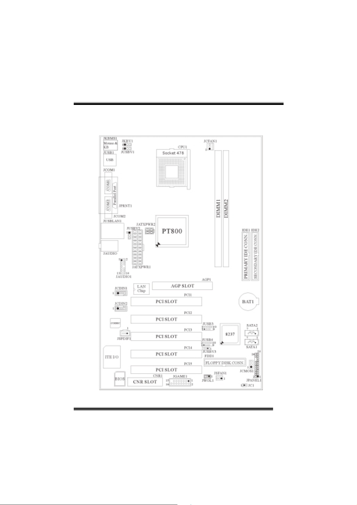
Layout of P4VTB
※
NOTE: ●represents the first pin.
1
Page 5
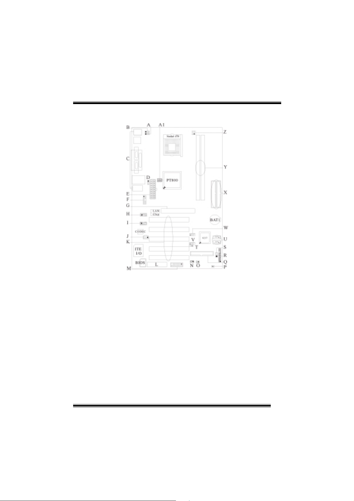
Component Index
A. Power Source Selection for USB (JUSBV1) M. Game Header (JGAME1) (p. 7)
(p. 10) N. Wake On LAN (JWOL1) (p. 8)
B. Power Source Selection for KB/MS (JKBV1) O. System FAN Header (JSFAN1) (p. 5)
(p. 10) P. Case Open Connector (JC1) (p. 11)
C. Back Panel Connector (p. 12) Q. Floppy Disk Connector (FDD1) (p. 6)
D. Power Source Selection for USB (JUSBV2) R. Front Panel Connector (JPANEL1) (p. 8)
(p. 10) S. Clear CMOS (JCMOS1) (p. 10)
E. ATX Power Connector (JATXPWR1) (p. 9) T. Power Source Selection for USB (JUSBV3)
F. Front Audio Header (JAUDIO1) (p. 9) (p. 10)
G. Accelerated Graphic Port Slot (AGP1) (p. 7) U. Serial ATA Connector (JSATA1-2) (p. 7)
H. CD-ROM Audio-In Header (JCDIN1) (p. 11) V. Front USB Header (JUSB4) (p. 8)
I. CD-ROM Audio-In Header (JCDIN2) (p. 11) W. Front USB Header (JUSB3) (p. 8)
J. Digital Audio Connector (JSPDIF1) (p. 11) X. IDE Connectors (IDE1-2) (p. 6)
K. PCI BUS Slots (PCI1-5) (p. 7) Y. DIMM Modules (DIMM1-2) (p. 6))
L. Communication Network Riser Slot Z. CPU Fan Connector (JCFAN1) (p. 5)
(CNR1) (p. 7) A1 ATX Power Connector (JATXPWR2) (p. 9)
2
Page 6

English
1. P4VTB Features
A. Hardware
CPU
Provides Socket 478.
Supports the Intel® Pentium 4 Processor.
Front Side Bus at 400/533/800 MHz.
Chipset
North Bridge: VIA PT800
South Bridge: VIA VT8237.
Main Memory
Supports up to 2 DDR devices.
Supports 200/266/333/400 MHz DDR devices.
Maximum memory size of 2GB.
Super I/O
Chip: ITE IT8705.
Slots
Five 32- PCI bus master slots.
One AGP slot.
One CNR slot.
On Board IDE
Supports four IDE disk drives.
Supports PIO Mode 4, Bride Mode and Ultra DMA 33/66/100/133 Bus Master
Mode.
Serial ATA
Chip: VT8237
Supports RAID 0, 1.
Supports 2 Serial ATA (SATA ) ports.
- compliant wi th SATA 1.0 specification.
- Data transfer rates up to 1.5 GB/s.
On Board AC’97 Sound Codec
Chip: CMI9739A.
Compliant with AC’97 specification.
AC’97 2.2 interface.
Supports 6 channels.
On Board Peripherals
a. Rear side
2 serial ports.
1 parallel port. (SPP/EPP/ECP mode)
Audio ports in vertical position.
3
Page 7
1 LAN port.
PS/2 mouse and PS/2 keyboard.
4 USB2.0 ports.
b. Front Side
1 floppy port supports 2 FDDs with 360K, 720K, 1.2M, 1.44M and 2.88Mbytes.
4 USB2.0 ports.
Dimensions
ATX Form Factor: 20.5 X 30.5cm. (W X L)
B. BIOS & Software
BIOS
Award legal Bios.
APM1.2.
ACPI.
USB Function.
Software
Supports WarpspeederTM, 9th TouchTM, FLASHER™, WinFlasher
StudioFun! (optional).
Offers the highest performance for Windows 98 SE, Windows 2000, Windows Me,
Windows XP, SCO UNIX etc.
TM
and WatchdogTM,
2. Package contents
HDD Cable X1
FDD Cab l e X1
User’s Manual X1
USB Cable X1 (optional)
Rear I/O Panel for ATX Case X1 (opti onal)
Fully Setup Driver CD X1
StudioFun! Application CD X1 (optional)
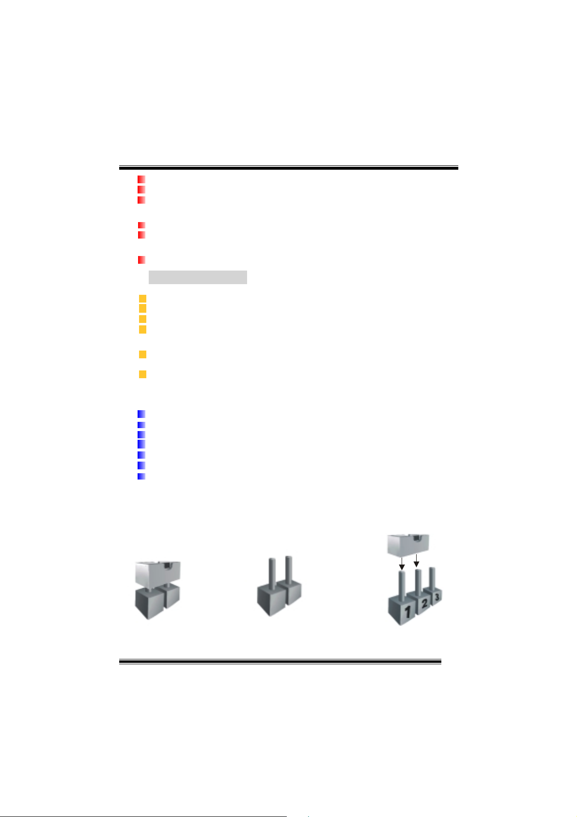
3. How to setup Jump er
The illustrati on shows how j umper s are set up. When the Jum per cap is place d on pin s, the
jumper is “close”. If no jumper cap is placed on the pins, the jumper is ”open”. The
illustration shows a 3-pin j umper whose pin 1and 2 are “close” when jumper cap is placed
on these 2 pins.
Jumper close Jumper open Pin 1-2 close
4
Page 8
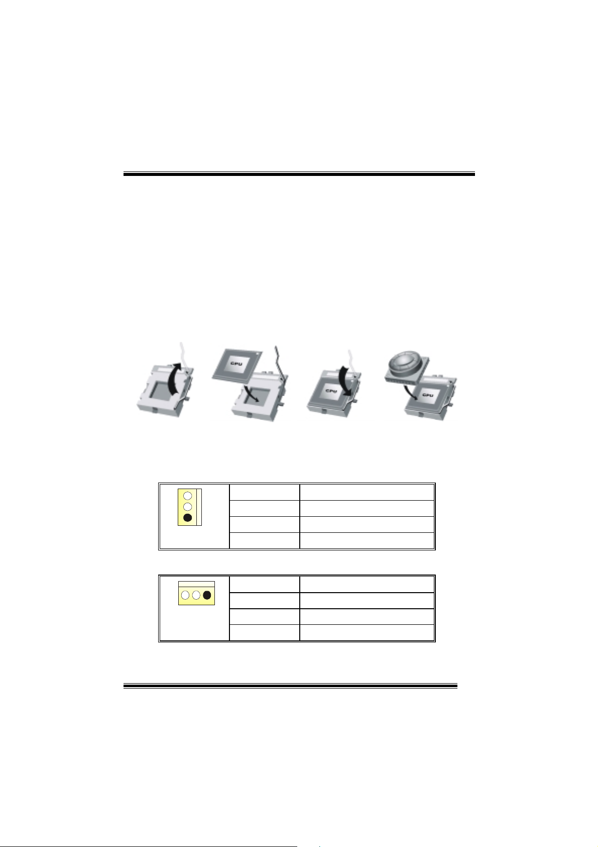
4. CPU Installation
Step1:
Step2: Look for the whit e do t/cut edge. The white dot/cut edge shoul d point towards the
Step3:
Step4: Put the CPU fan on the CPU and buckle it. Connect the CPU fan power cable to
Pull the lever sideways away from the socket and then raise the lever up to a
90-degree angle.
lever pivot. The CPU will fit only in the correct orientation.
Hold the CPU down firmly, and then close the lever.
the JCFAN1. This completes the installation.
Step1 Step2 Step3 Step4
CPU Fan Headers: JCFAN1
3
1
JCFAN1
System Fan Head e rs : JS F A N 1
13
JSFAN1
Pin No. Assign ment
1
2
3
Ground
+12V
FAN rpm Rate Sense
Pin No. Assign ment
1
2
3
5
Ground
+12V
FAN rpm Rate Sense
Page 9
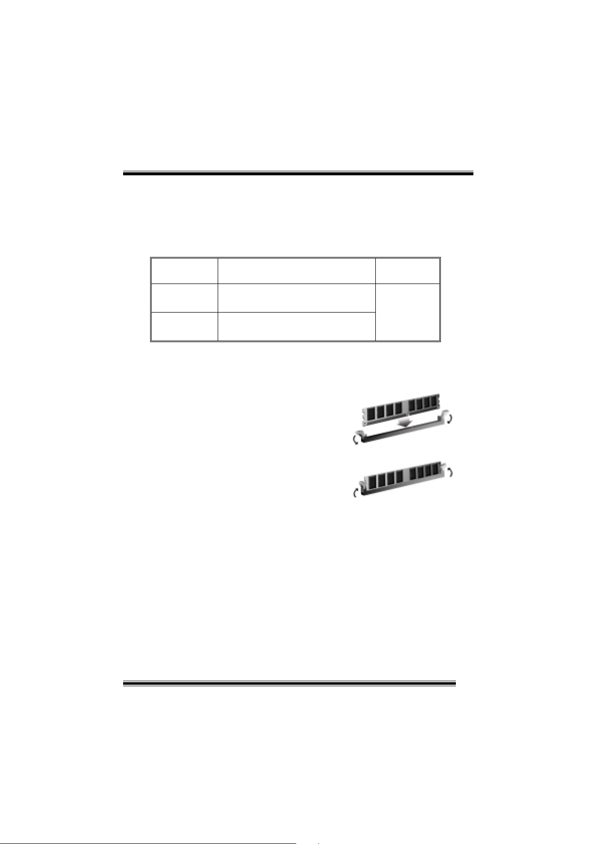
5. DDR DIMM Modules: DIMM1/ DIMM2
DRAM Access Time: 2.5V Unbuffered DDR 200/266/333/400 MHz Type required.
DRAM Type: 64MB/ 128MB/ 256MB/ 512MB/ 1GB D IMM Module (184 p in)
Total Memory Size with Unbuffered DIMMs
DIMM Socket
DDR Module Total Mem or y
Location
DIMM1 64MB/128MB/256MB/512MB/1GB
*1
DIMM2 64MB/128MB/256MB/512MB/1GB
*1
***Only for re f erence ***
Installing DDR Module
1. Unlock a DIMM slot by pressing the
retaining clips outward. Align a DIMM on
the slot such that the notch on the DIMM
matches the break on the slot.
2. Insert the DIMM firmly and vertically into
the slot until the retaining chip snap back in
place and the Dimm is properly seated.
6. Jumpers, Headers, Connectors & Slots
Size (MB)
Max is
2GB
(1) Floppy Disk Connector: FDD1
The motherboard provides a standard floppy disk connector that supports 360K,
720K, 1.2M, 1.44M and 2.88M floppy disk types. This connector supports the
provided floppy drive ribbon cables.
(2) Hard Disk Connectors: IDE1/ IDE2
The motherboard has a 32-bit Enhanced PCI IDE Controller that provides PIO
Mode 0~4, Bus Master, and Ultra DMA 33/ 66/ 100/ 133 functionality. It has two
HDD connectors IDE1 (primary) and IDE2 (secondary).
The IDE connectors can connect a master and a slave drive, so you can connect
up to four hard disk drives. The first hard drive should always be connected to
IDE1.
6
Page 10
(3) Peripheral Component Interconnect Slots: PCI 1-5
This motherboard is equipped with 5 standard PCI slots. PCI stands for Peripheral
Component Interconnect, and it is a bus standard for expansion cards. This PCI
slot is designated as 32 bits.
(4) Accelerated Graphics Port Slot: AGP1
Your monitor will attach directly to that video card. This motherboard supports
video cards for PCI slots, but it is also equipped with an Accelerated Graphics Port
(AGP). An AGP card will take advantage of AGP technology for improved video
efficiency and performance, especially with 3D graphics.
(5) Communication Network Riser Slot: CNR1
The CNR specification is an open Industry Standard Architecture, and it defines a
hardware scalabl e ri ser card interface, which supports modem only.
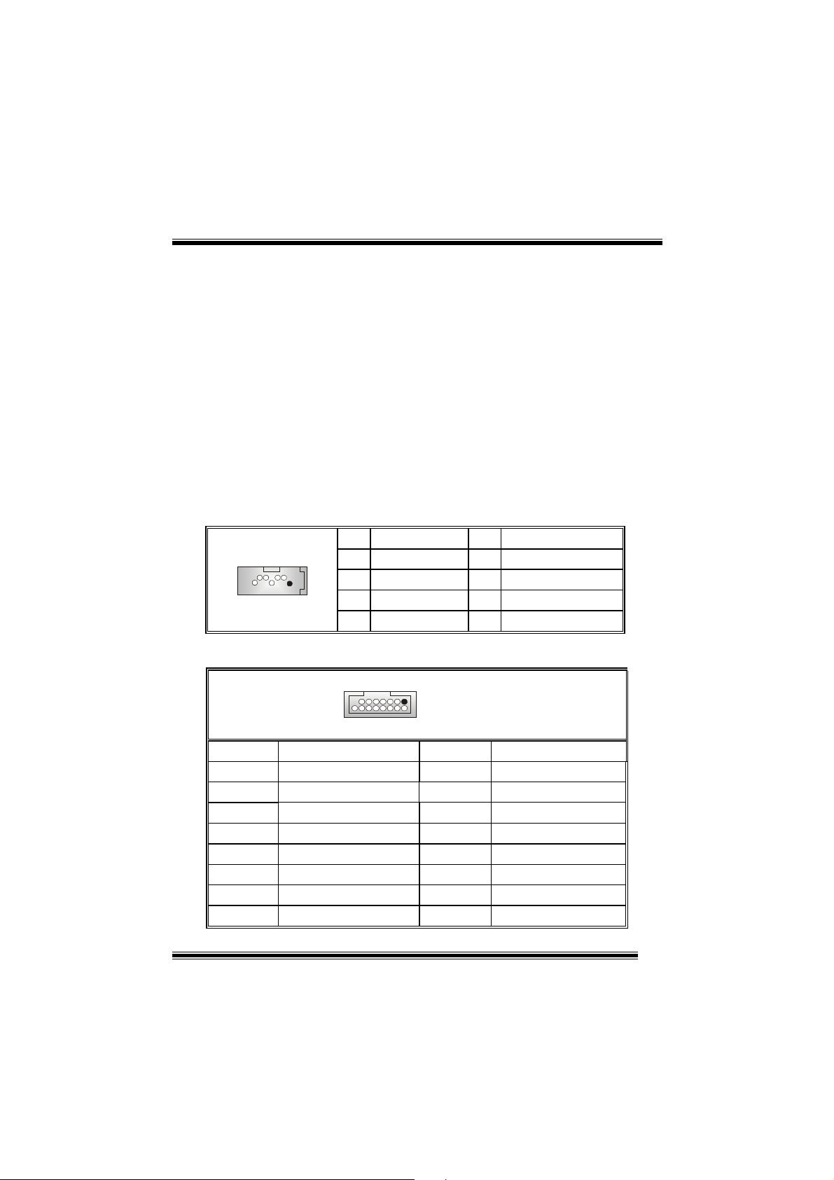
(6) Serial ATA Connector: JSATA1/ JSATA2
The motherboard has a PCI to SATA Controller with 2 channels SATA interface, it
satisfies the SATA 1.0 spec and can transfer data wi th 1.5GHz speed.
1234567
JSATA1/ JSATA2
Pin Assignment Pin Assignment
1
3
5
7
Ground
TX-
RX-
Ground
2
4
6
TX+
Ground
RX+
(7) Game Header: JGAME1
15
1
216
JGAME1
Pin Assignment Pin Assignment
1
3
5
7
9
11
13
15
Joystick B Coordin ate X
Joystick B Coordin ate Y
+5V
Joystick B Button 1
MIDI Output
Joystick B Button 2
MIDI Input
NA
2
4
6
8
10
12
14
16
Joystick A Coordi nate X
Joystick A Coordi nate Y
+5V
Joystick A Button 1
Ground
Ground
Joystick A Button 2
+5V
7
Page 11
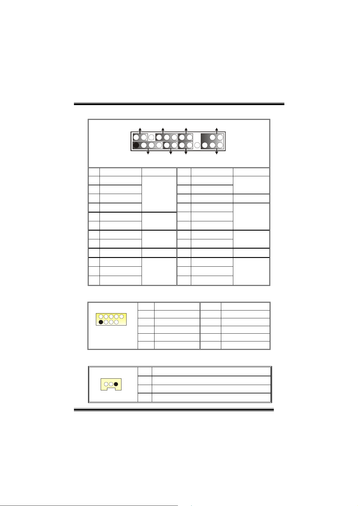
(8) Front Panel Connector: JPANEL1
SLP
JPANEL1
Pin Assignment Function Pin Assignment Function
1
3
5
7
9
HDD LED (+)
11
HDD LED (-)
13
15
Reset Con trol
17
19
21
23
2
1
+5V
NA
NA
Speaker
Ground
NA
NA
+5V
IRTX
PWR_LED
(+) (-)(+)
SPK
Speaker
Connector
Hard Drive
LED
Reset
Button
IrDA
Connector
(+) (-)
HLED
RST
2
4
6
8
10
12
14
16
18
20
22
24
IRON/OFF
24
23
IR
Sleep Control
Ground
NA NA
Power LED (+)
Power LED (+)
Power LED (-)
Power But t o n
Ground
KEY
KEY
Ground
IRRX
Sleep
Button
POWER
LED
Power-on
Button
IrDA
Connector
(9) Front USB Header: JU SB3/ JUSB4
2
1
JUSB3/4
Pin Assignment Pin Assignment
10
1
3
9
5
7
9
+5V(fused)
USBP4-
USBP4+
Ground
KEY
2
4
6
8
10
+5V(fused)
USBP5-
USBP5+
Ground
NA
(10) Wake On LAN Header: JWOL1
JWOL1
Pin Assignment
1
1
2
3
+5V_SB
Ground
Wake up
8
Page 12
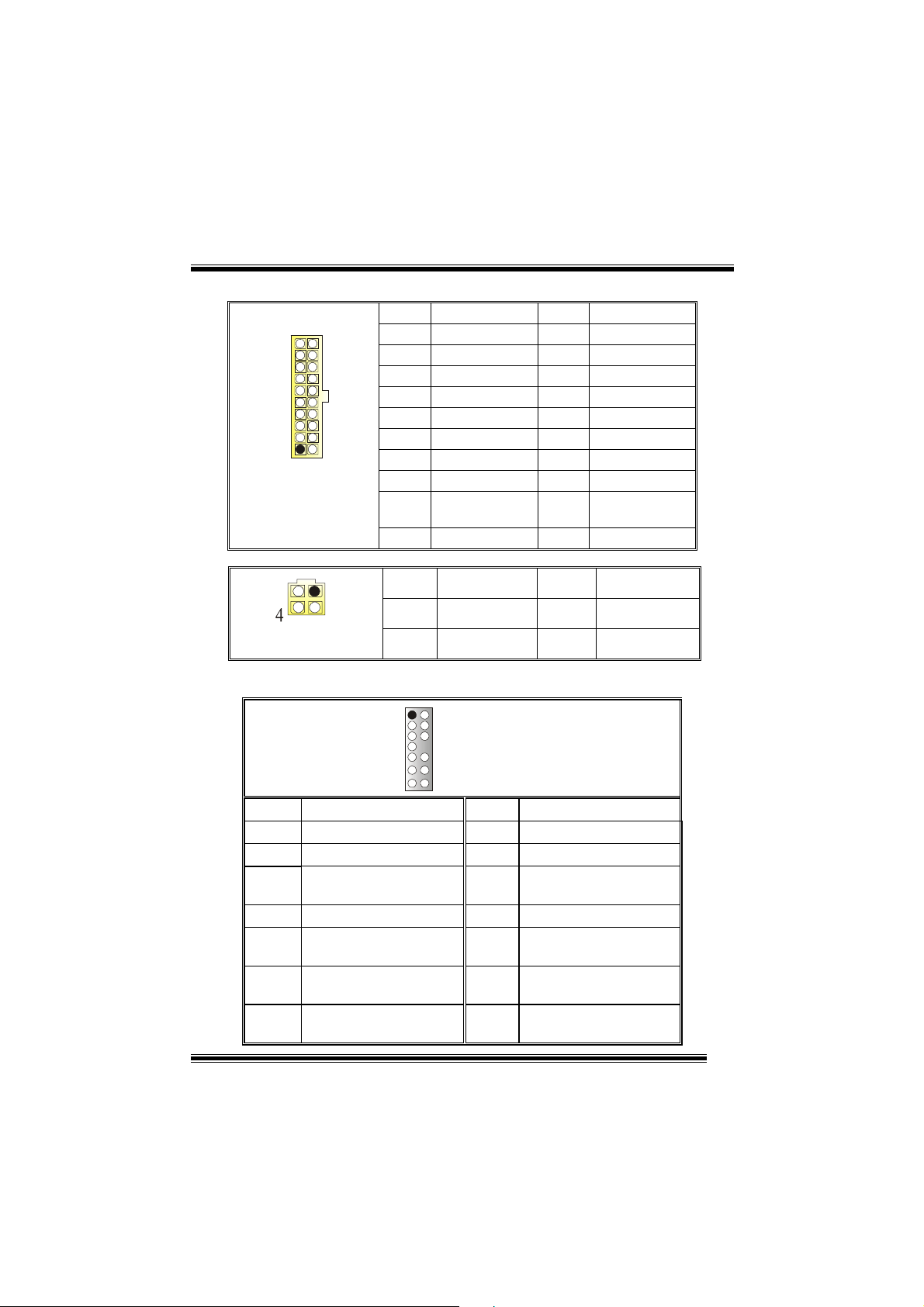
(11) Power Connectors: JATXPWR1
PIN Assignment PIN Assignment
1 +3.3V 11 +3.3V
2 +3.3V 12 -12V
3 Ground 13 Ground
4 +5V 14 PS_ON
5 Ground 15 Ground
6 +5V 16 Ground
7 Ground 17 Ground
8 PW_OK 18 -5V
9 Standby Voltage
10 +12V 20 +5V
PIN Assignment PIN Assignment
1
2
10
JATXPWR1
JATXPWR2
20
1
11
12
3
+5V
+12V
+12V
(12) Front Panel Audio Header: JAUDIO1
12
19 +5V
3
4
Ground
Ground
13 14
Pin Assignment Pin Assignment
1
3
5
7
9
11
13
Mic In/ Center
Mic Power/ Bass
Right Line Out/ Speaker
Out Right
Reserved
Left Line Out/ Speaker
Out Left
Right Line In/ Rear
Speaker Right
Left Line In/ Rear Speaker
Left
JAUDIO1
2
4
6
8
10
12
14
9
Ground
Audio Power
Right Line Out/ Speaker
Out Right
Key
Left Line Out/ Speaker
Out Left
Right Line In/ Rear
Speaker Right
Left Line In/ Rear Speaker
Left
Page 13

(13) Power Source Selection for KB: JKBV1
JKBV1 Assignment
Description
1 3
Pin 1-2 close
1 3
Pin 2-3 close
+5V
+5V Standby
Voltage
+5V for keyboard and mouse
PS/2 Mouse and PS/2 Keyboard are
powered with +5V standby voltage
(14) Power Source Selection for USB: JUSBV1/ JUSBV2/
JUSBV3
JUSBV1/JUSBV2/
JUSBV3
1 3
Pin 1-2 close
1 3
Pin 2-3 close
Assignment Description
+5V Standby
+5V
Voltage
JUSBV1: 5V for USB located at the
JUSB1 connector port
JUSBV2: 5V for USB located at the
JUSBLAN1 connector port
JUSBV3: 5V for USB located at the
JUSB3/4 connector ports
JUSBV1: JUSB1 port powered with
standby voltage of 5V
JUSBV2: JUSBLAN1 port powered with
standby voltage of 5V
JUSBV3: JUSB3/4 port powered with
standby voltage of 5V
(15) Clear CMOS Jumper: JCMOS1
JCMOS1 Assignment
3
1
Pin 1-2 Close
3
1
Pin 2-3 Close
Normal Operation (default)
Clear CMOS Data
10
Page 14

The following procedures are for re se tting the
BIOS password. It is important to follow these
instructions closely.
※ Clear CMOS Proced ures:
1. Remove AC power line.
2. Set the jumper to “Pin 2-3 close”.
3. Wait for five seconds.
4. Set the jumper to “Pin 1-2 close”.
5. Power on AC.
6. Reset your desired password or clear the CMOS data.
(16) Case Open C onnector: JC 1
Pin
1
1
JC1
2
Assignment
Case Open Signal
Ground
(17) CD-ROM Audio-In Header: JCDIN1/ (JCDIN2→→→→optional)
1
JCDIN1/ 2
Pin Assignment
1
2
3
4
(18) Digital Audio Connector: JSPDIF1
Pin Assignment
1
J_SPDIF1
1
2
3
11
Left Channel Input
Ground
Ground
Right Channel Input
+5V
SPDIF_OUT
Ground
Page 15

(19) Ba ck Panel Conn ectors
JKBMS1
PS/2
Mouse
PS/2
Keyboard
JPRNT1
JUSB1
USB
COM1
JCOM1
6 Channel Speakers
Speaker Out
Parallel
COM2
JCOM2
12
JUSBLAN2
Line In
Speaker Out
MIC I n
USB
JAUDIO1
Line In/ Rear Speaker
Mic In/ Center & Bass
Page 16

StudioFun!TM
Introduction
StudioFun!TM is a media-player based on optimized GNU/Linux distribution to bring a
“Room Theater” experience into life. It plays DVD, VCD, MP3, Audio CD and other
multimedia. Furthermore, Users can take snapshots of video and customize the saved
images as screensavers or p h oto sl i deshows. Of course, the images can b e st or ed in USB
mass storage devices like flash disks and USB floppy disks.
Hardware Requirement s
The supported hardware list of StudioFun! updates regularly. So please check the
“hwreq.txt” located in the root of StudioFun! Application Pack CD to get the latest
supporting information.
Installation Procedure
Insert the “StudioFun! Application Pack CD” in a CD/DVD ROM drive and let the system
boot through th e C D. Th e di s k wi ll boo t and bri ng u p t he g rub boot l oad er i nstal l ation menu.
Two options are specified: “ S tudioFun Install” and “StudioFun Recover”.
13
Page 17

StudioF un! Insta l l
This option will do the basic installation of the distribution. The installation works on
pre-installed windows or GNU/Linux distribution.
On selecting the “StudioFun Install” option the installer boots and displays a dialog box
indicating the space required and waits for a confirmation. Selecting “Ok” will continue the
installation while selecting “Cancel” will terminate the installation and reboot the machine.
If Windows or GNU/Linux is the only OS installed on the hard disk with no free space, it
will resize the partition, either NTFS or FAT32 or ext2, and install StudioFun!. If the hard
disk has a 128MB of free space available, the installation will use the free space.
After installing the base system you will be prompted to select the resolution from the
following choices
1. 1024x768 (recommended)
2. 800x600
3. 640x480
Select the desired resolution. The default is 1024x768 for high-end graphics.
Next you will be prompted to choose the DVD area/region selection code. Choose this
based on the type of DVDs you will be playing.
The installation procedure will then probe for the type of mouse installed. The distribution
currently supports PS/2, USB and Serial mice. In case of serial mouse you will have to
move the mouse when prompted. The other two are probed and installed automatically .
The installation procedure will now finish, the CD is ejected and a dialog box prompting to
reboot the machine is displ ayed. Press “OK” button and enjoy StudioFun!.
3.1.1 Error Messages
1. Media corrupted!! Please check the media! The CD-ROM is corrupted.
2. Extraction of base system fai led!!
3.Unsupported hardware found, Aborting...
unsupported and undocumented hardware the above error message is popped.
4. No device found!
This error message is give n if there is no hard disk in the syste m .
Please try again later!! The CD-ROM is corrupted.
If you try to install StudioFun! on an
14
Page 18

StudioFun! Recover
Where there is a MBR (Master Boot record) corruption, the “StudioFun Recover” will
automatically probe the hard disk master boot record and find out the installed operating
system(s). Once success, it will re-install the boot loader with correct options in the MBR.
Please be noted that the newly probed one will over write any custom boot loader option
specified from other GNU/Linux installations.
Booting to StudioFun!
After the Installation, remove the CD from the CD-ROM and restart the system. After the
rebooting, you will get the “GR UB boot loader men u scr een”. Sel ect the Stu di oFun! Opti on
to boot to the StudioFun! Partition.
15
Page 19

After executing t he boo t up, y ou will see the main Deskt o p sc re en. The foll ow ing sect ion i s
a complete description of the Desktop application.
Desktop
This is the main shell of the StudioFun! software. It illustrates two main categories, one is
the main "Media Control
" part and the other is the "Control Panel".
Media control
The Media Control consists of the following functionalities:
1. VCD
This control i con w ill gl ow wh enever a VC D i s d ete cted in a DVD/CD-ROM dri ve. T h e V CD
will be auto-played only when it is put in to the drive when the Desktop (StudioFun! shell)
is up and running whereas the control will simply glow to inform the user about a VCD
16
Page 20

present in the DVD/CD-ROM drive when the Desktop is not launched.
2. DVD
This control will glow whenever a DVD is detected in a DVD drive. The DVD will be
auto-played only when it is put in to the drive when the Desktop (StudioFun! shell) is up
and running, otherwise, the control will simply glow to inform the user about a DVD
present in the DVD/CD-ROM.
3. MP3
This control will glow whenever a MP3 is detected in a DVD/CD-ROM drive. The MP3 will
be auto-play ed only when it is put in to the drive when the De sktop (StudioFun! shell) is up
and running, otherwise, the control will simply glow to inform the user about a MP3
present in the DVD/CD-ROM drive.
4. AUDIO
This control will glow wheneve r a AUDIO is dete cted in a DVD/ CD-R OM drive. The AUDI O
will be auto-played
is up and running, otherwise, the control wi ll simply glow to inform the user about a AUDIO
present in the DVD/CD-ROM drive.
only
when it is put in to the drive when the Desktop (StudioFun! shell)
5. FILE
This control will gl ow whenever a File CD (CDs with ot her media type files) i s detected in a
DVD/CD-ROM drive. The File CD will be auto-played only when it is put in to the drive
when the Desktop (StudioFun! shell) is up and running, otherwise, the control will simply
glow to inform the user about a Fil e CD present in the DVD/CD-ROM drive.
6. EJECT MEDIA
When clicked this control, the file disk from the DVD/CDROM drives will be ejected.
7. EXIT
This is the "Power on/off" control of the Desktop (StudioFun! shell).
Control Panel
The Control panel part has five icons, which are shortcuts to other applications present in
the StudioFun!. Tool tips will pop up once the mouse is rolled to the icons
1. Select Region
Clicking this icon will invoke the application for selection DVD region settings. Refer to
section 5.2 Select DVD Region application for more details.
17
Page 21

2. Screensaver
Clicking this icon will invoke the screensaver application. Refer to section 5.3
Screensaver for more details.
3. Display Settings
Clicking this icon will invoke the application for changing the screen resolutions. Refer to
section 5.4, Display Settings for more details.
4. File Manager
Clicking this icon will invoke the file manager. Refer to section 5.6 File manager for more
details.
When user has a DVD and a CD-ROM Driv e, DVD Drive has the prior ity:
If user has both DVD and a CD-ROM drive, DVD drive will be given the preference when
both the drives h ol d valid media in them, i.e. , i f the CD -R OM drive has a media and a D VD
drive also has a media, and th e Studi oFun ! is s tar te d, the dis k i nside th e DVD dr ive will be
played.
Other general user scenarios
When a user clicks on any of the media-controls when it is not glowing, except the eject
media and exit, the media-player will just come up and wait for user input.
18
Page 22

Software Details
XINE
XINE is a multimedia player. It plays back Audio CD, DVD, and VCD. It also decodes
multimedia files like AVI, MOV, WMV, and MP3 from loca l disk drives. It interprets most of
the common multimedia formats.
• Features of Xine
a. Skinnable GUI
b. Navigation c ontrols (seeking , pause, fast, slow, next
chapter, etc)
c. On Screen Display (OSD) features
d. DVD and external subtitles
e. DVD/VCD menus (requires external plug-in)
f. Audio and subtitle channel selection
g. Closed Caption support
h. Brightness, contrast, audio volume, hue, saturation
adjusting requires hardware/driver s up p ort)
i. Playlist
j. Image snapshot
k. Audio re-sampling
l. Software de-interlacing algorithms
m. Configuration dialog
n. Aspect ratio changing
o. Full-screen display
• Supported File Formats
a. Video CD
b. MPEG program stream s (.mpg, .mpeg)
c. ogg (.ogg) avi (.avi)
d. asf (.asf, .wmv)
e. QuickTime (.mov)
f. MPEG-Video (.mpv, .m2v)
19
Page 23

g. MPEG-Audio (.mp2, .mp3)
h. WAV (.wav) Video CODE C
i. MPEG 1/2
j. MPEG 4 (aka OpenDivX)
k. MS MPEG 4
a. Chapter 5: Software Details 10
l. Windows Media Video 7
m. Motion JPEG
• Remote Control Support.
a. Infrared interface
b. User-friendly
• Usage of StudioFun! with CelomaChrome skin
a. Select VCD button to play a VCD disc
b. Select DVD button to play a DVD disc
c. Select CDDA button to play a Audio CD
d. Select next chapter or MRL (>>|) button to play next track
in Audio CD, VCD and MP3 songs and to play next
chapter in DVD
e. Select previous chapter or MRL (|<<) button to play
previous track in Audio CD, VCD and MP3 songs and to
play previous chapter in DVD
f. Select slow motion (<<) button to play the video / audio in
slow motion (Select play button after reaching the required
position)
g. Select fast motion (>>) button to play the video / audio in
fast motion (Select play button after reaching the required
position)
h. Select subs + / - button to select the appropriate subtitle
(Usable while playing
i. Select audio + / - button to select the appropriate audio
track (For example when
j. The DVD contains one audio track in English and the
other with some other language,
k. Usable while playing DVD’s)
l. Select “hide button” to hide the control panel of the player
20
Page 24

m. Select “menu” button to use menu while playing DVD
n. Select “control” button to ad just brightness / color
o. Select “setup” button to modify the setting s of the player
p. Select ”f.scr” button to show the video output of the player
in full screen mode
q. Select “snap” button to take a snapshot of the currently
playing video
r. Select “plis t” button to add / remove / mana ge playlist
s. Select “mrl” button to add new f ile to pla y
Select Region
Overview
Select region is a utility to set a DVD region. With the help of this application user can set
or change a DVD region. Only one region can be set at a time.
About Select Region
With the help of this application you can set a region for DVD. Only one region can be set
at a time. If you keep the mouse pointer on any region, you can view the countries, which
comes under that region.
“Ok” - Click to set the selected region.
“Cancel” - Click to quit the application.
How to select DVD region
You can select only one region at a time. You can change your selecti on by clicking on
any other region.
• A snapshot of the application is shown below:
21
Page 25

Screensaver
Screensaver
The xscreensaver da emo n w ait s un ti l the key boar d and mou se ha ve be en idl e for a peri od,
and then runs a graphics demo chosen at random. The demo is terminated as soon as
there is any mouse or keyboard activity.
The xscreensaver-demo program is the graphical user interface to xscreensaver. It lets
you tune the various parameters used by the xscreensaver daemon, and browse through
the graphics demos.
StudioFun! comes with xscreensaver when you click on the screensaver i con the
application comes up. Then user can choose various graphics demos l ike
chbg,halo,hypercube or hyperball.
Screensaver comes with various options
• Preview Option: When a user selects a particular graphics demo and clicks on preview
button the demo comes up.
• Blank After Option: The screensaver will blank the screen after the key board and mouse
have been idle default time is 1minute and user can change the settings.
• Cycle After Option: When screensaver is running this cycle time defines the time limit for
each screensaver.
• Mode Screensaver comes with various modes:
1. Random Screen Saver: When user chooses this option, Screensaver cycles through
various graphics demos randomly
22
Page 26

2. Only one Screen Saver: When user chooses this opt ion, screensaver displays onl y one
graphics demo.
3. Blank Screen Onl y: When user choose s t his op tion, screensa ver onl y bl anks the scr ee n
instead of displaying the graphics demo.
4. Disable Screen Saver: When user chooses this option, screensaver is disabled.
• Various Graphics Demos
XScreensaver comes with various screensaver
Chbg: This screensaver displays the images stored in StudioFun! the time gap between
images is 5 seconds.
Hyperball
Hypercube
Halo
Strange
• A snapshot of the application is shown below:
23
Page 27

Display Settings
Display Settings
Display setting is a program to change the current resolution settings of the Displ ay.
By default user of StudioFun! will be given a choice to select between any of the following
three resolutions.
• 640x480
• 800x600
• 1024x768
The current resolution of the Display will be selected by default. It requires restart of the
StudioFun! to reflect the changes made.
File Manager
Overview
File manger is a u ti lity to copy fil es from de fer ent devi ce s t o h ard di sk an d vi ce ver s a. U se r
can copy files from devices such as, floppy, CD-Rom and Flashdisk to hard disk and also
from hard disk to floppy and Flashdisk.
About File manager
The hard disk files are stored in a directory called “/ studiofun” on the hard disk. Y ou can
also delete files from hard disk, but you cannot delete files from any device.
Select device - Contains the device names /floppy, /cdrom and /flashdisk. Select a
device from/t o which y ou want t o copy fil es.
twice to m ou n t th e de vice .
List Directories - Shows the list of directories of the selected device after double
clicking it .
Floppy/cdrom/Flashdisk - Shows the contents of the selected directory from the “List
directories“ field after double clicking it.
Hard disk - Shows the contents of a directory called “/studiofun”.
Add (>>) - Click to copy sel ected files from a device to hard di sk.
Add (<<) - Click to copy sel ected files from hard disk to a devi ce.
Remove - Click to delete fi les from hard disk.
Exit - Click to quit the application.
Please double cl ick t he device option
24
Page 28

25
Page 29

WarpSpeeder
Introduction
[ WarpSpeeder™ ], a new powerful control utility, features three user-friendly functions
including Overclock Manager, Overvoltage Manager, and Hardware Monitor.
With the Overcl ock Mana ge r, use r s can ea si ly adjust the fre quen cy they prefer or they can
get the best CPU performance with j u st one click. The Overvoltage Manager, o n the other
hand, helps to power up CPU core voltage and Memory voltage. The cool Hardware
Monitor smartly indicates the temperatures, voltage and CPU fan speed as well as the
chipset information. Also, in the About panel, you can get detail descriptions about BIOS
model and chipsets. In addition, the frequency status of CPU, memory, AGP and PCI
along with the CPU speed are sy nchronically shown on our main panel.
Moreover, to protect users' computer systems if the setting is not appropriate when test ing
and results in system fail or hang, [ WarpSpeeder™ ] technology assures the system
stability by automatically rebooting the computer and then restart to a speed that is either
the original system speed or a suitable one.
System Requirement
OS Support: Windows 98 SE, Windows Me, Windows 2000, Windows XP
DirectX: DirectX 8.1 or above. (The W indows XP operating system includes DirectX 8.1. If
you use Windows XP, you do not need to install DirectX 8.1.)
26
Page 30

Installation
1. Execute the setup execution file, and then the following dialog will pop up.
Please click “N ext” button and follow the default procedure to install.
2. When you see the following dialog in setup procedure, it means setup is
completed. If the “Launch the WarpSpeeder Tray Utility” checkbox is checked,
the Tray Icon utility and [WarpSpeeder™] utility will be automatically and
immediately launched after you click “Finish” button.
27
Page 31

Usage
The following figures are just only for reference, the screen printed in this user manual will
change according to your motherboard on hand.
[WarpSpeeder™] includes 1 tray icon and 5 panels:
1. Tray Icon:
Whenever the Tray Icon util i ty is laun ched, it will displ ay a little t ray ico n on th e r igh t side o f
Windows Taskbar.
28
Page 32

This utility is responsible for conveniently invoking [WarpSpeeder™] Utility. You can use
the mouse by clicking the left button in order to invoke [WarpSpeeder™] directly from the
little tray icon or you can right-click the little tray icon to pop up a popup menu as following
figure. The “Launch Utility” item in the popup menu has the same function as mouse
left-click on tray icon and “Exit” item will close Tray Icon utility if select ed.
2. Main Panel
If you click the tray icon, [ WarpSpeeder™ ] utility will be invoked. Please refer
do the following figure; the utility’s first window you will see is Main Panel.
Main Panel contains features as follows:
a. Display the CPU Speed, CPU external clock, Memory clock, AGP clock, and PCI
clock information.
b. Contains About, Voltage, Overclock, and Hardware Monitor Buttons for invoking
respective panels.
c. With a user-friendly Status Animation, it can represent 3 overclock percentage
stages:
Duck walking => overclock percentage from 100% ~ 110 %
Duck running => overclock percentage from 110% ~ 120%
Duck burning => overclock percentage from 120% ~ above
29
Page 33

3. Voltage Panel
Click the Voltage button in Main Panel, the button will be highlighted and the Voltage
Panel will slide out to up as the following figure.
In this panel, you can decide to increase CPU core voltage and Memory voltage or not.
The default setting is “No”. If you want to get the best performance of overclocking, we
recommend you click the option “Yes”.
30
Page 34

4. Overclock Panel
Click the Overclock button in Main Panel, the button will be highlighted and the Overclock
Panel will slide out to left as the following figure.
31
Page 35

Overclock Panel contains these features:
a. “–3MHz button”, “-1MHz button”, “ +1 MHz butt on”, an d “+3 MHz button”: provi de use r
the ability to do real-time overclock adjustment.
Warning: Manually overclock is potentially dangerous, especially when the
overclocking percentage is over 110 %. We strongly recommend you verify
every speed you overclock by click the Verify button. Or, you can just click
Auto overclock button and let [ WarpSpeeder™ ] automatically gets the best
result for you.
b. “Recovery Dialog button”: Pop up the following dialog. Let user select a restoring
way if system need to do a fail-safe reboot.
32
Page 36

d. “Auto-overclock button”: User can click this button and [ WarpSpeeder™ ] will set
the best and stable performance and frequency automatically. [ WarpSpeeder™ ]
utility will execute a serie s of testin g until s ystem fail. Then system w ill do fail-saf e
reboot by using Watchdog function. After reboot, the [ WarpSpeeder™ ] utility will
restore to the hardware default setting or load the verified best and stable
frequency according to the Recovery Dialog’s setting.
e. “Verify button”: User can click this button and [ WarpSpeeder™ ] will proceed a
testing for current frequency. If the testing is ok, then the current frequency will be
saved into system registry. If the testing fail, system will do a fail-safe rebooting.
After reboot, the [ WarpSpeeder™ ] utility will restore to the hardware default
setting or load the verified best and stable frequency according to the Recovery
Dialog’s setting.
Note: Because the testing programs, invoked in Auto-overclock and Verify,
include DirectDraw, Direct3D and DirectShow tests, the DirectX 8.1 or newer
runtime library is required. And please make sure your display card’s color
depth is High color (16 bit) or True color( 24/32 bit ) that is required for
Direct3D rendering.
33
Page 37

5. Hardware Monitor Panel
Click the Hardware Monitor button in Main Panel, the button will be highlighted and the
Hardware Monitor panel will sli de out to left as the following figure.
In this panel, you can get the real-time status information of your system. The information
will be refreshed every 1 second.
6. About Panel
Click the About button in Main Panel, the button will be highlighted and the About Panel
will slide out to up as the following figure.
In this panel, you can get model name and detail information in hints o f all the chipset that
are related to overclocking. You can also get the mainboard’s BIOS model and the
Version number of [ WarpSpeeder™ ] utility.
34
Page 38

Note: Because the overclock, overvoltage, and hardware monitor features
are controlled by several separate chipset, [ WarpSpeeder™ ] divide these
features to separate panels. If one chipset is not on board, the correlative
button in Main panel will be disabled, but will not interfere other panels’
functions. This property can make [ WarpSpeeder™ ] utility more robust.
35
Page 39

Trouble Shooting
PROBABLE SOLUTION
No power to the system at all; power light doesn’t
illuminate; fan inside power supply does not turn
on. Indicator light on keyboard does not turn on.
PROBABLE SOLUTION
System inoperative. Keyboard lights are on,
power indicator lights are lit , and hard drive is
spinning.
PROBABLE SOLUTION
System does not boot fro m h ard disk dr i ve, but it
can be booted from CD-ROM drive.
PROBABLE SOLUTION
System only boots fr om CD- RO M. H ard di sk can
be read and applications can be used but
booting from hard disk is impossible.
* Make sure power cable is securely plugged in.
* Replace cable.
* Contact technical support.
* Using even pressure on both ends of the
DIMM, press down firmly until the module
snaps back in places.
* Check ca bl e r unning from di sk to disk con t roller
board. Make sure both ends are securely
plugged in; check the drive type in the
standard CMOS setup.
* Backing up the hard drive is extremely
important. All hard disks are capable of
breaking down at any time.
* Back up data and app li c ati ons file s. Ref or m at
the hard drive. Re-install applications and data
using backup disks.
PROBABLE SOLUTION
Screen message s ays “Invalid C onfiguratio n” or
“CMOS Failu re.”
* Review system’s equipment. Make sure correct
information is in setup.
PROBABLE SOLUTION
Cannot boot syst em af ter ins tallin g sec ond h ard
drive.
* Set master/slave jumpers correctly.
* Run SETUP progra m and select correct drive
types. Call drive manufacturers for
compatibility with other drives.
PROBABLE SOLUTION
Error message reading “SECTOR NOT FOUND”
or other error messages not allowing certain data
to be retrieved.
* Back up any salvageable data. Then, low- level
format, partition, and high-level format the
hard drive. Re-install all saved data when
completed.
PROBABLE SOLUTION
Scree is blank. * Check the p ower con nect ors t o mo nitor and to
system. Make sure monitor is connected to
display card.
36
Page 40

PROBABLE SOLUTION
Screen goes blank periodically. * Disable screen saver.
PROBABLE SOLUTION
Memory problem. * Reboot computer. Reinstall memory, and make
sure that all memory modules are installed in
correct sockets.
PROBABLE SOLUTION
Computer virus. * Use anti-virus programs to detect and clean
viruses.
PROBABLE SOLUTION
Keyboard failure. * Rec onnect keybor ad. Check keys ag ain. If no
improvement, replace keyboard.
PROBABLE SOLUTION
No display on screen. * If possible, conn ec t moni tor to a not her system.
If no color still, replace monitor.
PROBABLE SOLUTION
C: drive failure. * Check hard drive cable.
PROBABLE SOLUTION
Missing operating system on hard drive. * Run setup and select correct drive type.
PROBABLE SOLUTION
Certain keys do not function. * Replace keyboard.
PROBABLE SOLUTION
Keyboard is locked, no keys function. * Unlock keyboard.
06/18/2003
37
 Loading...