

Page 1

P
4
T
S
E
S
S
E
E
P
P
4
T
4
T
FCC Information and Copyright
This equipment has been tested and f oun d to comply with th e limits of a
Class B digital device, pursuant to Part 15 of the FCC Rules. These limits
are designed to provide reasonable protection against harmful
interference in a residential installation. This equipment generates, uses
and can radiate radio frequency energy and, if not installed and used in
accordance with the instructions, may cause harmful interference to radio
communications. Th ere is no guarantee th at interferenc e will not occur in
a particular installa tion.
The vendor makes no representations or warranties with respect to the
contents here of and specially disclaims any implied
merchantability or fitness for any purpose. Furt her the vendor reserves
the right to revise this publication and to make changes to the contents
here of without obligation to notify any party beforehand.
Duplication of this publicati on , in pa rt or in wh ole, is not allow ed w ith out
first obtaining the vendor’s approval in w r iting.
The content of this us er’s manua l is subject to be chan ged without n otice
and we will not be responsible for any mistakes found in this user’s
manual. All the brand and product names are trademarks of their
respective companies.
warranties
of
i
Page 2

C
o
n
t
e
n
t
C
C
o
o
n
t
e
n
t
n
t
e
n
t
LAYOUT OF P4TSE.................................................................................1
COMPONENT INDEX.............................................................................2
ENGLISH...................................................................................................3
P4TSE Features..........................................................................................................3
Package contents.......................................................................................................5
How to set up Jumper................................................................................................5
CPU Installation..........................................................................................................5
DDR DIMM Modules: DDRA1-2, DDRB1-2................................................................6
Installing DDR Module...............................................................................................8
Jumpers, Headers, Connectors & Slots...................................................................8
WARPSPEEDER.....................................................................................15
Introduction ..............................................................................................................15
System Requirement................................................................................................15
Installation................................................................................................................16
Usage ........................................................................................................................17
STUDIOFUN!TM......................................................................................25
Introduction ..............................................................................................................25
Hardware Requirements..........................................................................................25
Installation Procedure..............................................................................................25
Booting to StudioFun! .............................................................................................27
Media control............................................................................................................28
Control Panel............................................................................................................29
Software Details .......................................................................................................30
Select Region............................................................................................................33
Screensaver..............................................................................................................34
Display Settings .......................................................................................................35
File Manager.............................................................................................................35
TROUBLE SHOOTING.........................................................................37
ii
Page 3
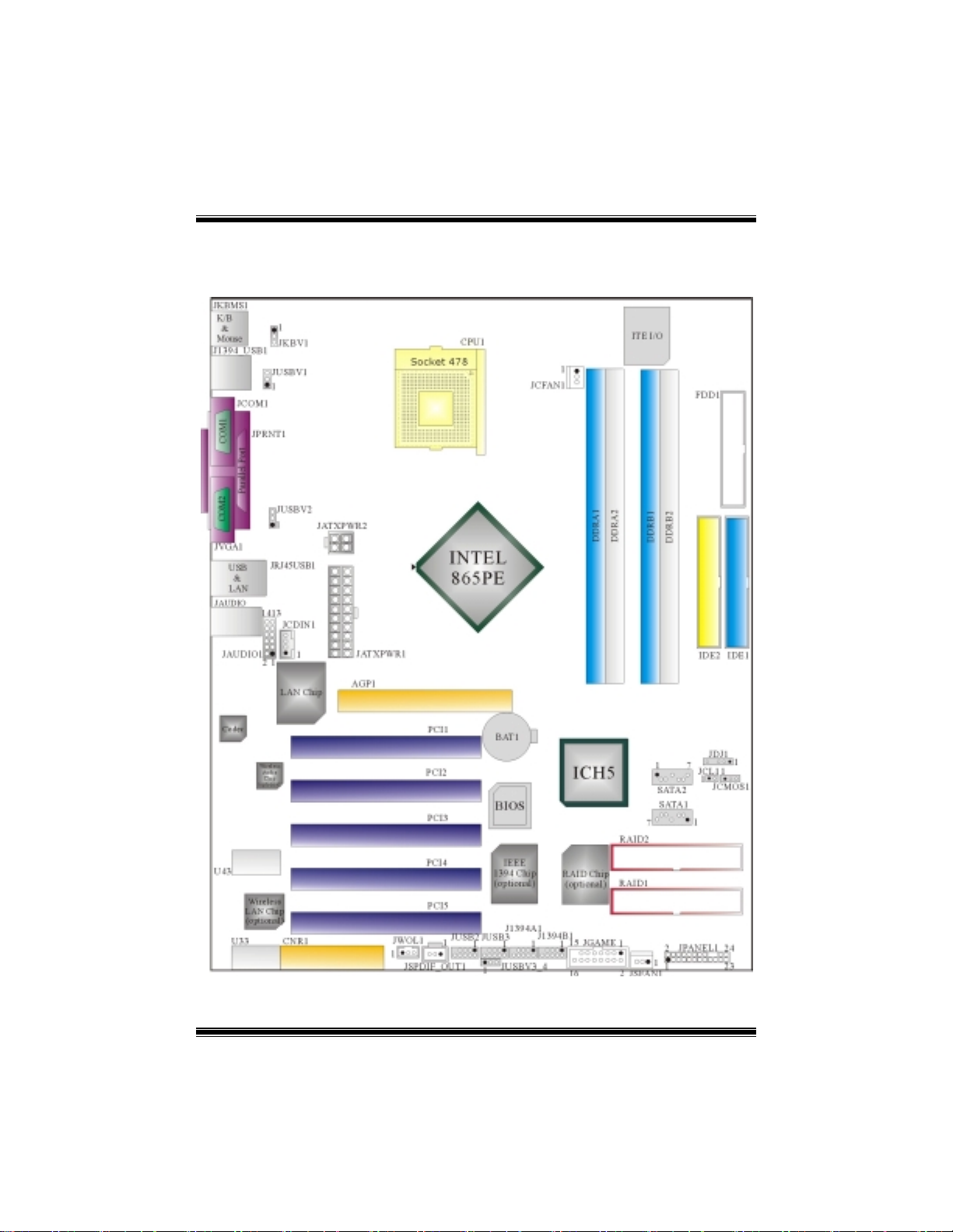
Layout of P4TSE
NOTE: ●represents the first pin.
1
Page 4
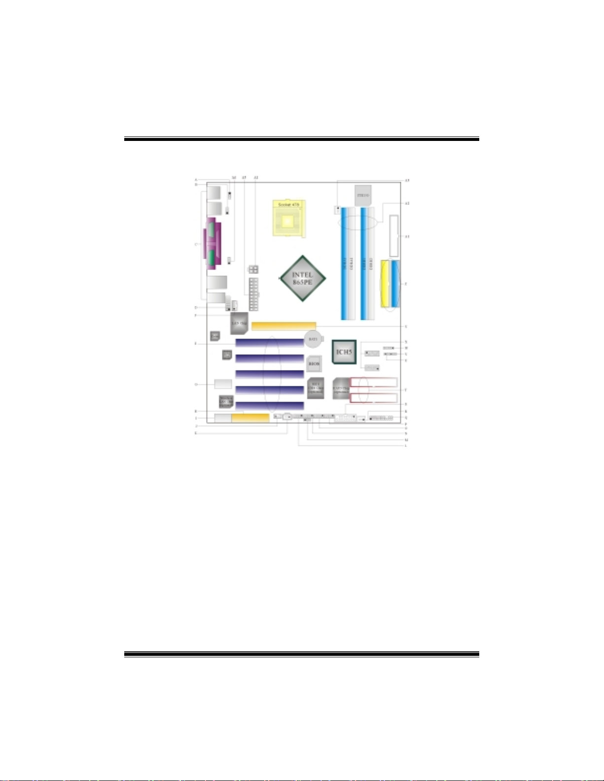
Component Index
A. JKBV1: Power Source Selection for
Keyboard/ Mouse
B. JUSBV1: Power Source Selection for
USB
C. Back Panel Connectors S. JGAME1: Game Port Header
D. JAUDIO1: Front Audio Header T. RAID1-2: Raid Connectors
E. PCI1-5: Peripheral Component
Interconnect Slots
F. JCDIN1: CD-ROM Audio-In Header V. JCMOS1: Clear CMOS Jumper
G. U43: Wireless Audio Connctor W. JDJ1: Audio DJ Connector
H. CNR1: Communication Network Riser
Slot
I. U33: Wireless LAN Connector Y. AGP1: Accelerated Graphic Port Slot
J. JWOL1: Wake On LAN Header Z. IDE1-2: Hard Disk Connectors
K. JSPDIF_OUT1: Digital Audio Connector A1. FDD1: Floppy Disk Connector
L. JUSB2: Front USB Header A2. DDRA1-2/DDRB1-2: DDR DIMM Modules
M. JUSBV3_4: Power Source Selection for
USB
N. JUSB3: Front USB Header A4. JATXPWR2: ATX Power Connector
O. J1394A1: Front 1394 Header (optional) A5. JATXPWR1: ATX Power Connector
P. J1394B1: Front 1394 Header (optional)
Q. JPANEL1: Front Panel Connector
R. JSFAN1: System Fan Header
U. JCL1: Case Open Connector
X. SATA1-2: Serial ATA Connectors
A3. JCFAN1: CPU Fan Connector
A6. JUSBV2: Power Source Selection for
USB
2
Page 5

English
P4TSE
Features
A. Hardware
CPU
Provides Socket-478.
Supports the Intel Pentium 4 processor to 3.06GHz+.
Front Side Bus at 400/533/800MHz.
Supports Hyper-Threading Technology.
Supports Northwood and Prescott CPU. (Willamette not supported)
Chipset
North Bridge: Intel 865PE.
South Bridge: Intel ICH5.
Main Memory
Supports one or two 64-bit wide DDR data channels with 1 or 2 DIMMs
per-channel.
Availabl e ban dwidth up to 3.2GB/s(DDR400) for s ing le-channel mode and 6.4GB/s
(DDR 400) in dual channel mode.
Supports 128-Mb, 256-Mb, 512-Mb DDR technologies.
Supports only x8, x16, DDR devices.( Does not support registered DIMMs and
double-sided X 16 DIMMs)
Supports four bank devices.
Maximum memory size is 4GB.
Super I/O
Chip: ITE IT8712.
Low Pin Count Interface.
Provides the most commonly used legacy Super I/O functionality.
Environment Control initiatives,
- H/W Monitor
- Fan Speed Controller
- ITE's "Smart Guardian" function
Slots
Five 32-bit PCI bus master slots.
One CNR slot.
One AGP 4X/8X slot.
On Board IDE
Supports four IDE disk drives.
Supports PIO Mode 5, Bride Mode and Ultra DMA 33/66/100 Bus Master Mode.
Supports 2 Serial ATA (SATA) ports.
3
Page 6

- Compliant with SATA 1.0 specification
-
Data transfer rates up to 1.5 Gb/
LAN (optional)
Chip: RTL8100B.
Supports 10 Mb/s and 100 Mb/s auto-negotiation
Half/Full duplex capability.
Supports ACPI power management
IEEE 1394A Chip (optional)
Chip: VIA VT6307.
Support 2 ports with transfer up to 400Mb/s.
On Board AC’97 Sound Codec
Chip: CMI9739A/ 9760.
Compliant with AC’97 specification.
AC97 2.2 interface.
Supports 6 channels.
On Board Peripherals
a. Rear side
2 serial ports.
1 parallel port. (SPP/EPP/ECP mode)
Audio ports in vertical position.
1 RJ-45 LAN jack. (optional)
Supports PS/2 mouse and PS/2 keyboard.
4 USB2.0 ports.
1 1394a Firewire port. (optional)
b. Front Side
1 floppy port supports 2 FDDs with 360K, 720K, 1.2M, 1.44M and 2.88Mbytes.
4 USB2.0 ports.
1 front audio header.
1 S/PDIF header.
1 1394a Firewire port. (optional)
Dimensions
ATX Form Factor: 24.4 X 30.5cm (W X L)
s
B. BIOS & Software
BIOS
Award legal BIOS.
Supports APM1.2.
Supports ACPI.
Supports USB Function.
Software
Supports Warpspeeder™, 9th Touch™, FLASHER™ and StudioFun! ™ (optional).
4
Page 7
Offers the highest performance for Windows 98 SE, Windows 2000, Windows M e,
Windows XP, SCO UNIX etc.
Package contents
HDD Cable X 1
FDD Cable X 1
User’s Manual X 1
Fully Setup Driver CD X 1
StudioFun! Application CD X 1 (optional)
USB 2.0 Cable X1 (optional)
S/PDIF Cable X 1 (optional)
Rear I/O Panel for ATX Case X 1
Serial ATA Cable X 1 (optional)
Serial ATA Power Switch Cable X 1 (optional)
IEEE 1394 Cable X 1 (optional)
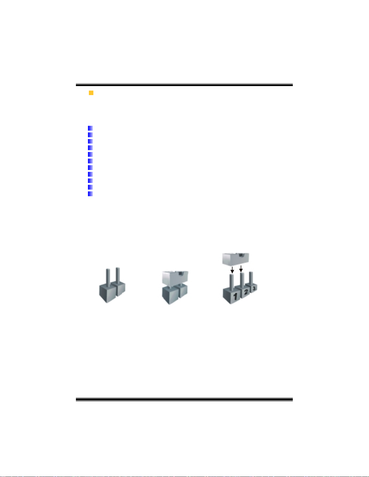
How to set up Jumper
The illustration shows to how set up jumper. When the Jumper cap is placed on pins, the
jumper is “close”. IF no jumper cap is placed on the pins, the jumper is ”open”. The
illustration shows a 3-pin jumper whose pin1and 2 are “close” when jumper cap is placed
on these 2 pins.
Jumper open Jumper close Pin1-2 close
CPU Installation
Step1: Pull the lever sideways away from the socket and then raise the lever up to a
90-degree angle.
Step2: Look for the white dot/cut edge. The white dot/cut edge should point wards the
lever pivot. The CPU will fit only in the correct orientation.
Step3: Hold the CPU down firmly, and then close the lever to complete the installation.
5
Page 8
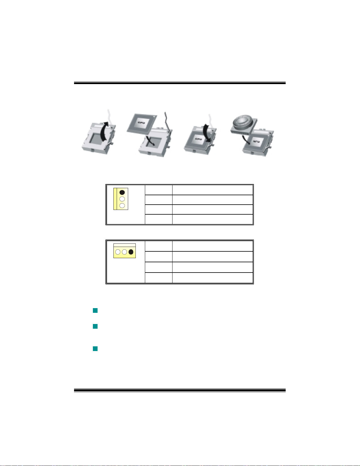
Step4: Put the CPU Fan on the CPU and buckle it. Connect the CPU fan power cable to
the JCFAN1. This completes the installation.
Step1 Step2 Step3 Step4
CPU Fan Header: JCFAN1
1
JCFAN1
Pin Assignment
1
2
3
Ground
+12V
FAN RPM rate Sense
System Fan Header: JSFAN1
Pin Assignment
1
JSFAN1
1
2
3
Ground
+12V
FAN RPM rate Sense
DDR DIMM Modules: DDRA1-2, DDRB1-2
Supports up to four DDR DIMMs(two DIMMs per channel), single-sided and/ or
double-sided.
For Dual Channel Operation, DIMMs must be populated in identical pairs. It
has to be the combination of DDRA1+DDRB1 (Blue DIMMs) or DDRA2+DDRB2
(white DIMMs).
Dual Channel Guidelines
Matched DIMM configuration in each channel
!" Same Density (128MB, 256MB, 512MB, 1GB, etc.)
!" Same DRAM technology (128M-bit, 256M-bit, or 512M-bit)
6
Page 9

!" Same DRAM bus width (x8 or x16)
!" Both either single-sided or dual-sided
Matched in both Channel A and Channel B memory channels
!" Populate symmetrical memory slots
Optimal platform performance with Dual Channel, DDR400, matched DIMMs
!" Fully loaded configurations can be single or double sided DIMMs
!" Lightly loaded configurations need to be double sided DIMMs
When not using DDR400, best performance obtained with
!" Symmetrical DIMM population and matched double-sided DIMMs
!" Lightly loaded configuration
Dual Channel Configuration Table
Dual Channel Configuration Table
•
DIMM Slot DDRA1 DDRA2 DDRB1 DDRB2 System
Density
Lightly
Loaded
128MB -1GB
128MB --
1GB
256MB --
Config
Lightly
Loaded
128MB --
1GB
128MB --
1GB
Config
Fully Loaded
Config
128MB -1GB
128MB -1GB
128MB -1GB
128MB -1GB
DRAM Access Time: 2.5V Unbuffered/ no registered (without ECC) DDR SDRAM
PC2100/ PC2700/ PC3200 Type required.
DRAM Type: 128MB/ 256MB/ 512MB/ 1GB DIMM Module (184 pin)
7
2GB
256MB --
2GB
512MB --
4GB
Page 10

Installing DDR Module
1. Unlock a DIMM slot by pressing the retaining clips
outward. Align a DIMM on the slot such that the
notch on the DIMM matches the break on the slot.
2. Insert the DIMM vertically and firmly into the slot
until the retaining chip snap back in place and the
DIMM is properly seated.
Jumpers, Headers, Connectors & Slots
Floppy Disk Connector: FDD1
The motherboard provides a standard floppy disk connector that supports 360K,
720K, 1.2M, 1.44M and 2.88M floppy disk types. This connector supports the
provided floppy drive ribbon cables.
Hard Disk Connectors: IDE1/ IDE2
The motherboard has a 32-bit Enhanced PCI IDE Controller that provides PIO
Mode 0~5, Bus Master, and Ultra DMA 33/ 66/ 100 functionality. It has two HDD
connectors IDE1 (primary) and IDE2 (secondary).
The IDE connectors can connect a master and a slave drive, so you can connect
up to four hard disk drives. The first hard drive should always be connected to
IDE1.
Peripheral Component Interconnect Slots: PCI 1-5
This motherboard is equipped with 5 standard PCI slots. PCI stands for Peripheral
Component Interconnect, and it is a bus standard for expansion cards. This PCI
slot is designated as 32 bits.
Accelerated Graphics Port Slot: AGP1
Your monitor will attach directly to that video card. This motherboard supports
video cards for PCI slots, but it is also equipped with an Accelerated Graphics Port
(AGP). An AGP card will take advantage of AGP technology for improved video
efficiency and performance, especially with 3D graphics.
Communication Network Riser Slot: CNR1
The CNR specification is an open Industry Standard Architecture, and it defines a
hardware scalable riser card interface, which supports modem only.
Serial ATA Connector: JSATA1/ JSATA2
The motherboard has a PCI to SATA Controller with 2 channels SATA interface, it
satisfies the SATA 1.0 spec and with transfer rate of 1.5Gb/s.
8
Page 11
Front Panel Connector: JPANEL1
SLP
2
JPANEL1
Pin Assignment Function Pin Assignment Function
1
3
5
7
9
HDD LED (+)
11
13
15
17
19
21
23
HDD LED (-)
Reset Control
1
+5V
NA
NA
Speaker
Ground
NA
NA
+5V
IRTX
PWR_LED
SPK
Speaker
Connector
Hard Drive
LED
Reset
Button
IrDA
Connector
HLED
RST
10
12
14
16
18
20
22
24
2
Sleep Control
4
6
8
Power LED (+)
Power LED (+)
Power LED (-)
Power Button
IRON/OFF
24
23
IR
Sleep
Ground
NA NA
Ground
KEY
KEY
Ground
IRRX
Button
POWER
LED
Power-on
Button
IrDA
Connector
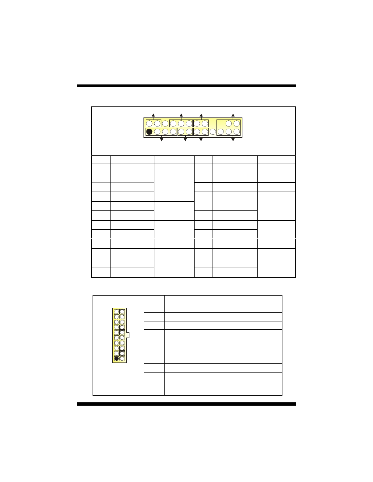
Power Connectors: JATXPWR1/ JATXPWR2
10
20
1
JATXPWR1
11
PIN Assignment PIN Assignment
1
2
3
4
5
6
7
8
9
10
+3.3V
+3.3V
Ground
+5V
Ground
+5V
Ground
PW_OK
Standby Voltage
+5V
+12V
11
12
13
14
15
16
17
18
19
20
+3.3V
-12V
Ground
PS_ON
Ground
Ground
Ground
-5V
+5V
+5V
9
Page 12
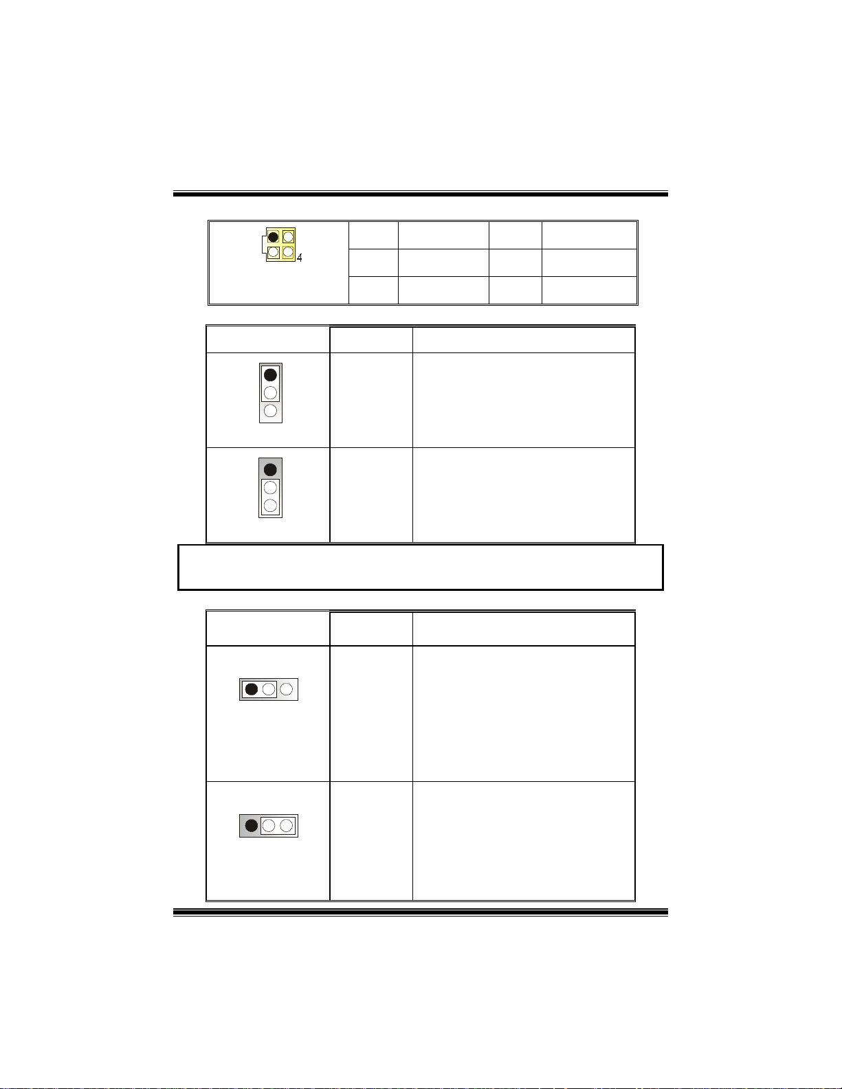
1
3
2
JATXPWR2
PIN Assignment PIN Assignment
1
2
+12V
+12V
3
4
Ground
Ground
Power Source Selection for Keyboard/ Mouse: JKBV1
JKBV1 Assignment Description
1
3
Pin 1-2 close
1
3
Pin 2-3 close
+5V
+5V Standby
Voltage
+5V for keyboard and mouse
PS/2 Mouse and PS/2 Keyboard are
powered with +5V standby voltage
Note: In order to support this function “Power-on system via keyboard and
mouse”, “JKBV1” jumper cap should be placed on pin 2-3.
Power Source Selection for USB: JUSBV1/ JUSBV2/ JUSBV3_4
JUSBV1/JUSBV2/
JUSBV3_4
1 3
Pin 1-2 close
Assignment Description
+5V
JUSBV1: 5V for USB at the JUSB1
connector port
JUSBV2: 5V for USB at the JRJ45USB1
coonector port
JUSBV3_4: 5V for USB at the JUSB2/3
connector ports
1 3
Pin 2-3 close
+5V Standby
Voltage
JUSBV1: JUSB1 port powered with
standby voltage of 5V
JUSBV2: JRJ45USB1 port powered
with standby voltage of 5V
JUSBV3_4: JUSB2/3 ports powered
with standby voltage of 5V
10
Page 13

Note: In order to support this function “Power-on system via USB device”,
“JUSBV1/JUSBV2/ JUSBV3_4” jumper cap should be placed on pin 2-3
individually.
Clear CMOS Jumper: JCMOS1
1 3
1 3
JCMOS1 Assignment
Pin 1-2 Close
Pin 2-3 Close
Normal Operation (default)
Clear CMOS Data
※ Clear CMOS Procedures:
1. Remove AC power line.
2. Set the jumper to “Pin 2-3 Close”.
3. Wait for five seconds.
4. Set the jumper to “Pin 1-2 Close”.
5. Power on the AC.
6. Reset your desired password or clear the CMOS data.
Case Open Connector: JCL1
Assignment
Case Open Signal
Ground
1
JCL1
Pin
2
1
2
Serial ATA Connector: JSATA1/ JSATA2
1234567
JSATA1/ JSATA2
Pin Assignment Pin Assignment
1
3
5
7
Ground
Ground
AUDIO DJ Connector: JDJ1
JDJ1
Pin Assignment Pin Assignment
1
15
3
5
SMBDATA
ATX_PWROK
TXRX-
INT_B
11
2
4
6
2
4
TX+
Ground
RX+
SMBCLK
KEY
Page 14

Game Header: JGAME1
15
Pin Assignment Pin Assignment
1
3
5
7
9
11
13
15
Joystick B Button 1
Joystick B Coordinate X
Joystick B Coordinate Y
Joystick B Button 2
+5V
MIDI Output
MIDI Input
NA
1
216
JGAME1
2
4
6
8
10
12
14
16
Joystick A Button 1
Joystick A Coordinate X
Joystick A Coordinate Y
Joystick A Button 2
CD-ROM Audio-In Header: JCDIN1
+5V
Ground
Ground
+5V
1
JCDIN1
Pin Assignment
1
2
3
4
Left Channel Input
Ground
Ground
Right Channel Input
Front Panel Audio Header: JAUDIO1
2
1
JAUDIO1
Pin Assignment Pin Assignment
1
3
5
7
9
11
13
Left Line In/ Rear Speaker Left
Mic In/ Center
Mic Power/ Bass
Right Line Out/ Speaker Out
Right
Reserved
Left Line Out/ Speaker Out
Left
Right Line In/ Rear Speaker
Right
14
13
2
4
6
Right Line Out/ Speaker Out R ight
8
10
Left Line Out/ Speaker Out Left
12
Right Line In/ Rear Speaker Right
14
Left Line In/ Rear Speaker Left
Ground
Audio Power
Key
12
Page 15

Digital Audio Connector: JSPDIF_OUT1
Pin Assignment
1
2
3
+5V
SPDIF_OUT
Ground
JSPDIF_OUT1
1
Wake On LAN Header: JWOL1
1
JWOL1
Pin Assignment
1
2
3
+5V_SB
Ground
Wake up
Front USB Header: JUSB2/3
9
10
JUSB2/3
Pin Assignment Pin Assignment
1
1
2
3
5
7
9
+5V(fused)
USB-
USB+
Ground
KEY
2
4
6
8
10
+5V(fused)
Front 1394 Header: J1394A1/ J1394B1 (optional)
9
10
J1394A1/ B1
Pin Assignment Pin Assignment
1
1
2
3
5
7
9
A+
Ground
B+
+12V
KEY
2
4
6
8
10
USBUSB+
Ground
NC
A-
Ground
B-
+12V
Ground
13
Page 16

Back Panel Connectors
JKBMS1
PS/2
Mouse
1394
(optional)
JPRNT1
Parallel
JRJ45USB1
LAN
(optional)
Line In
Speaker Out
Mic In
PS/2
Keyboard
J1394_USB1
USB
COM1
JCOM1
6 Channel Speakers
Speaker Out
COM2 USB
JCOM2
Line In/ Rear Speaker
Mic In/ Cente r & Bass
JAUDIO
14
Page 17

WarpSpeeder
Introduction
[ WarpSpeeder™ ], a new powerful control utility, features three user-friendly functions
including Overclock Manager, Overvoltage Manager, and Hardware Monitor.
With the Overclock Manager, users can ea si ly ad just the frequency they prefer or they c an
get the best CPU performance with just one click. The Overvoltage Manager, on the other
hand, helps to power up CPU core voltage and Memory voltage. The cool Hardware
Monitor smartly indicates the temperatures, voltage and CPU fan speed as well as the
chipset information. Also, in the About panel, you can get detail descriptions about BIOS
model and chipsets. In addition, the frequency status of CPU, memory, AGP and PCI
along with the CPU speed are synchronically shown on our main panel.
Moreover, to protect users' co mputer systems if the set ting is not appropriate when testing
and results in system fail or hang, [ WarpSpeeder™ ] technology assures the system
stability by automatically rebooting the computer and then restart to a speed that is either
the original system speed or a suitable one.
System Requirement
OS Support: Windows 98 SE, W indows Me, Windows 2000, Windows XP
DirectX: DirectX 8.1 or above. (The Windows XP operating system includes DirectX 8.1. If
you use Windows XP, you do not need to install DirectX 8.1.)
15
Page 18

Installation
1. Execute the setup execution file, and then the following dialog will pop up.
Please click “Next” button and follow the default procedure to install.
2. When you see the following dialog in setup procedure, it means setup is
completed. If the “Launch the WarpSpeeder Tray Utility” checkbox is checked,
the Tray Icon utility and [WarpSpeeder™] utility will be automatically and
immediately launched after you click “Finish” button.
16
Page 19

Usage
The following figures are just only for reference, the screen printed in this user manual will
change according to your motherboard on hand.
[WarpSpeeder™] includes 1 tray icon and 5 panels:
1. Tray Icon:
Whenever the Tray Icon ut ility i s launc hed, it w ill display a litt le tray ic on on th e right sid e of
Windows Taskbar.
17
Page 20

This utility is responsible for conveniently invoking [WarpSpeeder™] Utility. You can use
the mouse by clicking the left button in order to invoke [WarpSpeeder™] directly from the
little tray icon or you can right-click the little tray icon to pop up a popup menu as following
figure. The “Launch Utility” item in the popup menu has the same function as mouse
left-click on tray icon and “Exit” item will close Tray Icon utility if selected.
2. Main Panel
If you click the tray icon, [ WarpSpeeder™ ] utility will be invoked. Please refer
do the following figure; the utility’s first window you will see is Main Panel.
Main Panel contains features as follows:
a. Display the CPU Speed, CPU external clock, Memory clock, AGP clock, and PCI
clock information.
b. Contains About, Voltage, Overclock, and Hardware Monitor Buttons for invoking
respective panels.
c. With a user-friendly Status Animation, it can represent 3 overclock percentage
stages:
Duck walking => overclock percentage from 100% ~ 110 %
Duck running => overclock percentage from 110% ~ 120%
Duck Burning => overclock percentage from 120% ~ above
18
Page 21

3. Voltage Panel
Click the Voltage button in Main Panel, the button will be highlighted and the Voltage
Panel will slide out to up as the following figure.
In this panel, you can decide to increase CPU core voltage and Memory voltage or not.
The default setting is “No”. If you want to get the best performance of overclocking, we
recommend you click the option “Yes”.
19
Page 22

4. Overclock Panel
Click the Overclock button in Main Panel, the button will be highlighted and the Overclock
Panel will slide out to left as the following figure.
20
Page 23

Overclock Panel contains the these features:
a. “–3MHz button”, “-1MHz button”, “+1MHz button”, and “+3MHz button”: provide
user the ability to do real-time overclock adjustment.
Warning: Manually overclock is potentially dangerous, especially when the
overclocking percent age is over 110 %. W e strongly recommend yo u verify
every speed you overc lock by click the Verify button. Or, you can just c lick
Auto overclock butto n and l et [ WarpSp eeder™ ] automatica lly gets t he best
result for you.
b. “Recovery Dialog button”: Pop up the following dialog. Let user select a restoring
way if system need to do a fail-safe reboot.
21
Page 24

c. “Auto-overclock button”: User can click this button and [ WarpSpeeder™ ] will set
the best and stable performance and frequency automatically. [ WarpSpeeder™ ]
utility will execute a series of testing until system fail. Then system will do fail-safe
reboot by using Watchdog function. After reboot, the [ WarpSpeeder™ ] utility will
restore to the hardware default setting or load the verified best and stable
frequency according to the Recovery Dialog’s setting.
d. “Verify button”: User can click this button and [ WarpSpeeder™ ] will proceed a
testing for current frequency. If the testing is ok, then the current frequency will be
saved into system registry. If the testing fail, system will do a fail-safe rebooting.
After reboot, the [ WarpSpeeder™ ] utility will restore to the hardware default
setting or load the verified best and stable frequency according to the Recovery
Dialog’s setting.
Note: Because the t esting programs, invoked in Auto-overclock and Verify,
include DirectDraw, Direc t3 D and DirectShow tests, the Direc tX 8.1 or ne wer
runtime library is required. And please mak e sure your display card ’s color
depth is High color (16 bit) or True color( 24/32 bit ) that is required for
Direct3D rendering.
22
Page 25

5. Hardware Monitor Panel
Click the Hardware Monitor button in Main Panel, the button will be highlighted and the
Hardware Monitor panel will slide out to left as the following figure.
In this panel, you can get the real-time status information of your system. The information
will be refreshed every 1 second.
6. About Panel
Click the About button in Main Panel, the button will be highlighted and the About Panel
will slide out to up as the following figure.
In this panel, you can get model name and detail information in hints of all the chipset that
are related to overclocking. You can also get the mainboard’s BIOS model and the
Version number of [ WarpSpeeder™ ] utility.
23
Page 26

Note: Because the overclock, overvoltage, and hardware monitor features
are controlled by several separate ch ipset, [ WarpSpeeder™ ] divide these
features to separate panels. If one chipset is not o n board, the correlative
button in Main panel will be disabled, but will not interfere other panels’
functions. This property can make [ WarpSpeeder™ ] utility more robust.
24
Page 27

StudioFun!TM
Introduction
StudioFun!TM is a media-player based on optimized GNU/Linux distribution to bring a
“Room Theater” experience into life. It plays DVD, VCD, MP3, Audio CD and other
multimedia. Furthermore, Users can take snapshots of video and customize the saved
images as screensaver s or photo sl ideshow s. Of co urse, the images can b e stored in U SB
mass storage devices like flash disks and USB floppy disks.
Hardware Requirements
The supported hardware list of StudioFun! updates regularly. So please check the
“hwreq.txt” located in the root of StudioFun! Application Pack CD to get the latest
supporting information.
Installation Procedure
Insert the “StudioFun! Application Pack CD” in a CD/DVD ROM drive and let the system
boot through the CD. The d isk will boot and brin g up the grub boot loader i nstalla tion m enu.
Two options are specified: “StudioFun Install” and “StudioFun Recover”.
25
Page 28

StudioFun! Install
This option will do the basic installation of the distribution. The installation works on
pre-installed windows or GNU/Linux distribution.
On selecting the “StudioFun Install” option the installer boots and displays a dialog box
indicating the space required and waits for a confirmation. Selecting “Ok” will continue the
installation while selecting “Cancel” will terminate the installation and reboot the machine.
If Windows or GNU/Linux is the only OS installed on the hard disk with no free space, it
will resize the partition, either NTFS or FAT32 or ext2, and install StudioFun!. If the hard
disk has a 128MB of free space available, the installation will use the free space.
After installing the base system you will be prompted to select the resolution from the
following choices
1. 1024x768 (recommended)
2. 800x600
3. 640x480
Select the desired resolution. The default is 1024x768 for high-end graphics.
Next you will be prompted to choose the DVD area/region selection code. Choose this
based on the type of DVDs you will be playing.
The installation procedure will then probe for the type of mouse installed. The distribution
currently supports PS/2, USB and Serial mice. In case of serial mouse you will have to
move the mouse when prompted. The other two are probed and installed automatically.
The installation procedure will now finish, the CD is ejected and a dialog box prompting to
reboot the machine is displayed. Press “OK” button and enjoy StudioFun!.
3.1.1 Error Messages
1. Media corrupted!! Please check the media! The CD-ROM is corrupted.
2. Extraction of base system failed!!
3.Unsupported hardware found, Aborting...
unsupported and undocumented hardware the above error message is popped.
4. No device found! This error message is given if there is no hard disk in the system.
Please try again later!! The CD-ROM is corrupted.
If you try to install StudioFun! on an
26
Page 29

StudioFun! Recover
Where there is a MBR (Master Boot record) corruption, the “StudioFun Recover” will
automatically probe the hard disk master boot record and find out the installed operating
system(s). Once success, it will re-install the boot loader with correct options in the MBR.
Please be noted that the newly probed one will over write any custom boot loader option
specified from other GNU/Linux installations.
Booting to StudioFun!
After the Installation, remove the CD from the CD-ROM and restart the system. After the
rebooting, you will get the “GRUB boot loa der me nu screen”. Select the Stu dio Fun ! O ptio n
to boot to the StudioFun! Partition.
After executing the bo ot up, y o u will see the main Des kto p sc reen. The following sectio n is
a complete description of the Desktop application.
27
Page 30

Desktop
This is the main shell of the StudioFun! software. It illustrates two main categories, one is
the main "Media Control
" part and the other is the "Control Panel".
Media control
The Media Control consists of the following functionalities:
1. VCD
This control icon w ill glow w henev er a VCD is d etected in a DV D/CD- ROM drive. The VCD
will be auto-played only when it is put in to the drive when the Desktop (StudioFun! shell)
is up and running whereas the control will simply glow to inform the user about a VCD
present in the DVD/CD-ROM drive when the Desktop is not launched.
2. DVD
This control will glow whenever a DVD is detected in a DVD drive. The DVD will be
28
Page 31

auto-played only when it is put in to the drive when the Desktop (StudioFun! shell) is up
and running, otherwise, the control will simply glow to inform the user about a DVD
present in the DVD/CD-ROM.
3. MP3
This control will glow whenever a MP3 is detected in a DVD/CD-ROM drive. The MP3 will
be auto-played only when it is put in to th e dr iv e when the Desktop (StudioFun! shell) is u p
and running, otherwise, the control will simply glow to inform the user about a MP3
present in the DVD/CD-ROM drive.
4. AUDIO
This control will glow whenev er a AUDIO is dete cted in a DVD /CD-R OM driv e. The AU DIO
will be auto-played only when it is put in to the drive when the Desktop (StudioFun! shell)
is up and running, otherwise, the contr ol will simply glow to inform the u ser ab out a AUDIO
present in the DVD/CD-ROM drive.
5. FILE
This control will gl ow whenever a File C D (C D s with other media ty pe f ile s) is detected in a
DVD/CD-ROM drive. The File CD will be auto-played only when it is put in to the drive
when the Desktop (StudioFun! shell) is up and running, otherwise, the control will simply
glow to inform the user about a File CD present in the DVD/CD-ROM drive.
6. EJECT MEDIA
When clicked this control, the file dis k from the DVD/CDROM drives will be ejected.
7. EXIT
This is the "Power on/off" control of the Desktop (StudioFun! shell).
Control Panel
The Control panel part has five icons, which are shortcuts to other applications present in
the StudioFun!. Tool tips will pop up once the mouse is rolled to the icons
1. Select Region
Clicking this icon will invoke the application for selection DVD region settings. Refer to
section 5.2 Select DVD Region application for more details.
2. Screensaver
Clicking this icon will invoke the screensaver application. Refer to section 5.3
Screensaver for more details.
29
Page 32

3. Display Settings
Clicking this icon will invoke the application for changing the screen resolutions. Refer to
section 5.4, Display Settings for more details.
4. File Manager
Clicking this icon will invoke the file manager. Refer to section 5.6 File manager for more
details.
When user has a DVD and a CD-ROM Drive, DVD Drive has the priority:
If user has both DVD and a CD-ROM drive, DVD drive will be given the preference when
both the drives hold v ali d medi a in th em, i.e., if the C D-R OM drive has a med ia and a D VD
drive also has a media, and th e Studio Fun ! is s tarte d, the disk inside the DVD drive will be
played.
Other general user scenarios
When a user clicks on any of the media-controls when it is not glowing, except the eject
media and exit, the media-player will just come up and wait for user input.
Software Details
XINE
XINE is a multimedia player. It plays back Audio CD, DVD, and VCD. It also decodes
multimedia files like AVI, MOV, WMV, and MP3 from local disk drives. It interprets most of
the common multimedia formats.
30
Page 33

• Features of Xine
a. Skinnable GUI
b. Navigation controls (seeking, pause, fast, slow, next
chapter, etc)
c. On Screen Display (OSD) features
d. DVD and external subtitles
e. DVD/VCD menus (requires external plug-in)
f. Audio and subtitle channel selection
g. Closed Caption support
h. Brightness, contrast, audio volume, hue, saturation
adjusting requires hardware/driver support)
i. Playlist
j. Image snapshot
k. Audio re-sampling
l. Software de-interlacing algorithms
m. Configuration dialog
n. Aspect ratio changing
o. Full-screen display
• Supported File Formats
a. Video CD
b. MPEG program streams (.mpg, .mpeg)
c. ogg (.ogg) avi (.avi)
d. asf (.asf, .wmv)
e. QuickTime (.mov)
f. MPEG-Video (.mpv, .m2v)
g. MPEG-Audio (.mp2, .mp3)
h. WAV (.wav) Video CODEC
i. MPEG 1/2
j. MPEG 4 (aka OpenDivX)
k. MS MPEG 4
a. Chapter 5: Software Details 10
l. Windows Media Video 7
m. Motion JPEG
• Remote Control Support.
a. Infrared interface
31
Page 34

b. User-friendly
• Usage of StudioFun! with CelomaChrome skin
a. Select VCD button to play a VCD disc
b. Select DVD button to play a DVD disc
c. Select CDDA button to play a Audio CD
d. Select next chapter or MRL (>>|) button to play next track
in Audio CD, VCD and MP3 songs and to play next
chapter in DVD
e. Select previous chapter or MRL (|<<) button to play
previous track in Audio CD, VCD and MP3 songs and to
play previous chapter in DVD
f. Select slow motion (<<) button to play the video / audio in
slow motion (Select play button after reaching the required
position)
g. Select fast motion (>>) button to play the video / audio in
fast motion (Select play button after reaching the required
position)
h. Select subs + / - button to select the appropriate subtitle
(Usable while playing
i. Select audio + / - button to select the appropriate audio
track (For example when
j. The DVD contains one audio track in English and the
other with some other language,
k. Usable while playing DVD’s)
l. Select “hide button” to hide the control panel of the player
m. Select “menu” button to use menu while playing DVD
n. Select “control” button to adjust brightness / color
o. Select “setup” button to modify the settings of the player
p. Select ”f.scr” button to show the video output of the player
in full screen mode
q. Select “snap” button to take a snapshot of the currently
playing video
r. Select “plist” button to add / remove / manage playlist
s. Select “mrl” button to add new file to play
32
Page 35

Select Region
Overview
Select region is a utility to set a DVD region. With the help of this application user can set
or change a DVD region. Only one region can be set at a time.
About Select Region
With the help of this application you can set a region for DVD. Only one region can be set
at a time. If you keep the mouse pointer on any region, you can view the countries, which
comes under that region.
“Ok” - Click to set the selected region.
“Cancel” - Click to quit the application.
How to select DVD region
You can select only one region at a time. You can change your selection by clicking on
any other region.
• A snapshot of the application is shown below:
33
Page 36

Screensaver
Screensaver
The xscreensaver daem on waits until the key bo ard and mouse have been idle for a peri od,
and then runs a graphics demo chosen at random. The demo is terminated as soon as
there is any mouse or keyboard activity.
The xscreensaver-demo program is the graphical user interface to xscreensaver. It lets
you tune the various parameters used by the xscreensaver daemon, and browse through
the graphics demos.
StudioFun! comes with xscreensaver when you click on the screensaver icon the
application comes up. Then user can choose various graphics demos like
chbg,halo,hypercube or hyperball.
Screensaver comes with various options
• Preview Option: When a user selects a particular graphics demo and clicks on preview
button the demo comes up.
• Blank After Option: The screensaver will blank the screen after the keyboard and mouse
have been idle default time is 1minute and user can change the settings.
• Cycle After Option: When screensaver is running this cycle time defines the time limit for
each screensaver.
• Mode Screensaver comes with various modes:
1. Random Screen Saver: When user chooses this option, Screensaver cycles through
various graphics demos randomly
2. Only one Screen Saver: When user chooses this option, screensaver displays only one
graphics demo.
3. Blank Screen Only: When user chooses this option, screensaver only blanks the screen
instead of displaying the graphics demo.
4. Disable Screen Saver: When user chooses this option, screensaver is disabled.
• Various Graphics Demos
XScreensaver comes with various screensaver
Chbg: This screensaver displays the images stored in StudioFun! the time gap between
images is 5 seconds.
Hyperball
Hypercube
Halo
Strange
• A snapshot of the application is shown below:
34
Page 37

Display Settings
Display Settings
Display setting is a program to change the current resolution settings of the Display.
By default user of StudioFun! will be given a choice to select between any of the following
three resolutions.
• 640x480
• 800x600
• 1024x768
The current resolution of the Display will be selected by default. It requires restart of the
StudioFun! to reflect the changes made.
File Manager
Overview
File manger is a u til ity to c opy f iles fro m def erent devices to hard d is k and v ice v ers a. U se r
can copy files from devices such as, floppy, CD-Rom and Flashdisk to hard disk and also
from hard disk to floppy and Flashdisk.
35
Page 38

About File manager
The hard disk files are stored in a directory called “/studiofun” on the hard disk. You can
also delete files from hard disk, but you cannot delete files from any device.
! Select device - Contains the device names /floppy, /cdrom and /flashdisk. Select a
device from/to which y ou w ant to co py file s.
twice to mount the device.
! List Directories - Shows the list of directories of the selected device after double
clicking it.
! Floppy / cdro m/Fl ash di sk - Shows the contents of the selec ted dire ctory from the “List
directories“ field after double clicking it.
! Hard disk - Shows the contents of a directory called “/studiofun”.
! Add (>>) - Click to copy selected files from a device to hard disk.
! Add (<<) - Click to copy selected files from hard disk to a device.
! Remove - Click to delete files from hard disk.
! Exit - Click to quit the application.
Please double click the dev ice optio n
36
Page 39

Trouble Shooting
PROBABLE SOLUTION
No power to the system at all Power light d on’t
illuminate, fan inside po wer supply does not turn
on. Indicator light on keyboard does not turn on
PROBABLE SOLUTION
System inoperative. Keyboard lights are on,
power indicator lights are lit, hard drive is
spinning.
PROBABLE SOLUTION
System does not boot fr om hard disk dri ve, can
be booted from CD-ROM drive.
PROBABLE SOLUTION
System only boots from CD-ROM. Hard disk can
be read and applications can be used but
booting from hard disk is impossible.
* Make sure power cable is securely plugged in
* Replace cable
* Contact technical support
* Using even pressure on both ends of the
DIMM, press down firmly until the module
snaps into place.
* Check cable running from disk to disk controller
board. Make sure both ends are securely
plugged in; check the drive type in the
standard CMOS setup.
* Backing up the hard drive is extremely
important. All hard disks are capable of
breaking down at any time.
* Back up data and appl ic ations files. Reformat
the hard drive. Re-install applications and data
using backup disks.
PROBABLE SOLUTION
Screen message says “Invalid Con figuration” or
“CMOS Failure.”
PROBABLE SOLUTION
Cannot boot system after installing second hard
drive.
* Review system’s equipment . Make sure
correct information is in setup.
* Set master/slave jumpers correctly.
* Run SETUP program and select correct drive
types. Call drive manufacturers for
compatibility with other drives.
37
Page 40

07/23/2003
38
 Loading...