

Page 1

IPMIP-GS Series
Motherboard layout reference
Contents
• Specications summary
• Motherboard layout
• Rear panel connectors
• Internal connectors
This manual is meant as a general reference guide. Refer to the product itself for actual specications.
Page 2
2
IPMIP-GS motherboard layout reference
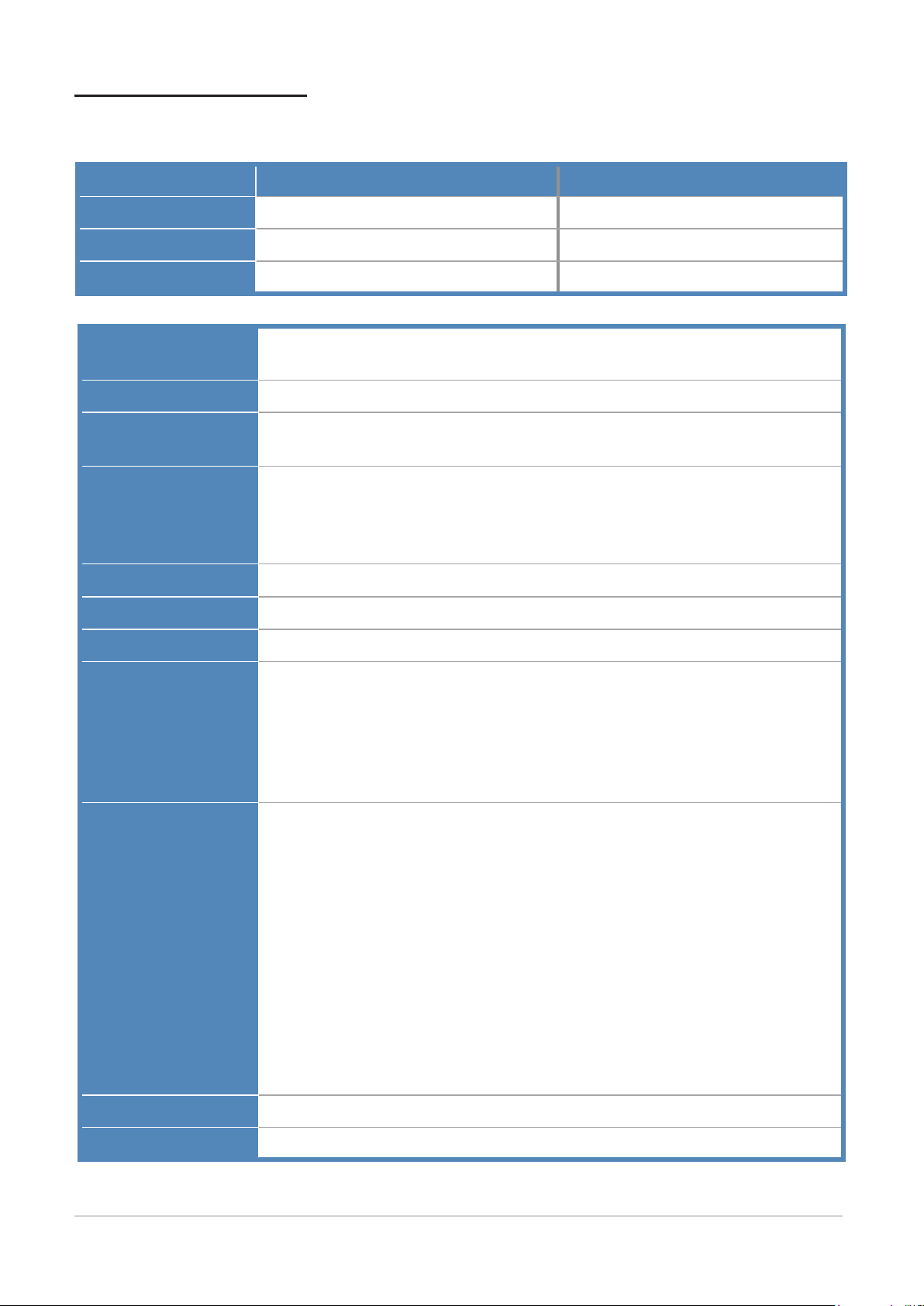
Specications summary
* The following components may be available depending on model.
Model HDMI port Audio Channel
Super model Optional 8-channel or 6-channel
H55 No HDMI port 5.1 channel
H57/Q57 No HDMI port 8-channel or 6-channel
CPU Socket : Intel Socket 1156
Supports : Clarkdale
Chipset North Bridge : Ibex peak (H55/H57/Q57)
Memory Dual-channel, 4 slots, Non-ECC, Unbuffered, 240 pin DDR3, Max. 16GB
Types: 1066/PC3-8500, 1333/PC3-10600
Expansion slots 1x PCI Express slot (x16)
1x PCI Express slot (x4)
1x PCI Express slot (x1)
1x PCI slot
Audio ALC888S-VC2 (8-channel) or ALC662 (6-channel)
LAN Gigabit: Intel hanksville (PHY)
USB 14x USB 2.0 ports, 12/480Mbps (12 ports on H55 sku)
Rear panel I/O ports 1x Mouse (PS/2) port + 1x Keyboard (PS/2) port
1x Display (VGA) port + 1x Display (DVI-I) port
* Display (HDMI) port
1x LAN (RJ-45) port + 2x USB 2.0 ports
2x USB 2.0 ports + 1x e-SATA port
6x Audio jacks (* Audio Channel)
Internal connectors 1x ATX CPU power connector
1x ATX power connector
1x CPU fan connector
1x System fan connector
5x SATA connectors
1x Front panel audio connector
2x Internal SPDIF output connectors
1x CD in connector
1x Internal serial port connector
5x USB 2.0 connectors
1x TPM connector
1x Chassis intrusion alarm connector
1x Front panel connector
BIOS SPI 64Mb for H/Q SKU (AMI)
Form factor microATX, 9.6 inches x 9.6 inches
Page 3
3
IPMIP-GS motherboard layout reference
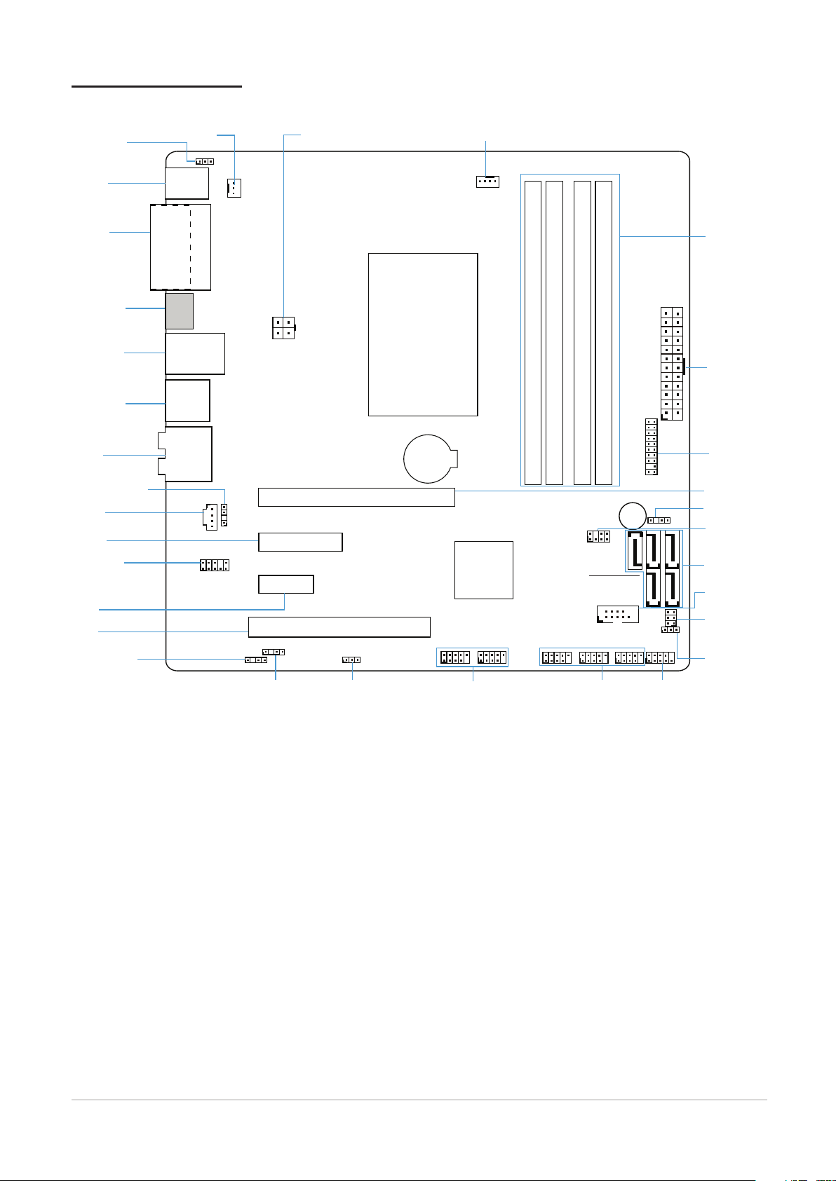
Motherboard layout
*HDMI port
(Depending on Model)
eSATA & USB
connectors
LAN & USB
connectors
Audio
ports
CD in
connector
Keyboard &
mouse
(PS/2) ports
ROM recovery
connector
SATA
connectors
Front panel
audio
connector
USB 2.0
connectors
FLASH override
selecter
USB 2.0
connectors
Memory
sockets
Front panel
connector
ATX power
connector
PCIE1
slot
PCIE4
slot
PCIE16 slot
Buzzer header
Internal serial
port connecto
r
Chassis Intrusion
Alarm Connector
Clear CMOS
& password
selectors
Internal SPDIF
output connector
Internal SPDIF
output connector
SPDIF_OUT1
INTRUDER
CD
AT X CPU Power
Connector
TPM
Connector
ATX_CPU
LAN + USB
AUDIO
CPU FAN
F_AUDIO
CMOS
+PW
ROM_RECOVERY
F_PANEL
F_USB5 F_USB4
FLASH_OVERRIDE
F_USB2 F_USB1F_USB3
PCIE X16 SLOT
PCIE X4 SLOT
XIMM2
XIMM1
XIMM4
XIMM3
PCIE X1 SLOT1
PCI SLOT
BATTERY
BUZZER
System Fan
Connector
Keyboard
Power selecter
CPU Fan
Connector
SYSTEM FAN
SW51
KB PWR
HDMI
eSATA + USB
TPM
SATA0
SATA
SATA4
SATA2
SATA3SATA1
SERIAL_A
ATXPOWER
KB +MS
Clear ME
data selector
Intel
LGA1156
socket
SPDIF_OUT2
PCI
slot
Display
ports
(DVI)(VGA)
DVI+VGA
BUZZER_HEADER
Page 4

4
IPMIP-GS motherboard layout reference
Rear panel connectors
Super model:
Mouse (PS/2)
port
Keyboard (PS/2)
port
H55:
Mouse (PS/2)
port
Display (VGA)
port
Display (DVI-I)
port
Display (VGA)
port
Display (HDMI) port
(optional)
LAN (RJ-45)
port
USB2.0
ports
LAN (RJ-45)
port
USB2.0
ports
e-SATA
port
USB2.0
ports
(Audio Channel: 8 or 6 channels)
Black: Side Surround L/R Out
Orange: Center/Subwoofer
Blue: Line In
Lime: Front L/R Out
Pink: Mic In
Gray: Rear Surround L/R Out
(Audio Channel: 5.1 channels)
Keyboard (PS/2)
H57/Q57:
Mouse (PS/2)
port
port
Display (DVI-I)
port
Display (VGA)
port
USB2.0
ports
LAN (RJ-45)
port
e-SATA
port
USB2.0
ports
Blue: Line In
Green: Front-L/R out
Pink: Mic In
(Audio Channel: 8 or 6 channels)
Black: Side Surround L/R Out
Orange: Center/Subwoofer
Blue: Line In
Lime: Front L/R Out
Pink: Mic In
Keyboard (PS/2)
port
Display (DVI-I)
port
USB2.0
ports
e-SATA
port
Gray: Rear Surround L/R Out
Page 5

5
IPMIP-GS motherboard layout reference
LAN port LED indications
(Default)
Clear CMOS
1
5
3
2
6
4
1
5
3
2
6
4
(Default)
Clear Password
1
5
3
2
6
4
2
6
4
1
5
3
1
3
2
(Default)
Flash override
1
3
2
(Default)
Normal
1
3
2
Clear
1
3
2
(Default)
1
3
2
1
3
2
+5VSB +5V_DUAL
Left (ACTIVITY)
Orange : Activity
Off : No Link
LAN port
Right (LINK)
Green : 1G Link
Orange : 100M Link
Off : 10M Link
Function Selectors
CMOS
CLEAR CMOS SELECTOR
To erase the CMOS RTC RAM user settings:
1. Turn OFF the computer and unplug the power cord.
2. Move the cap to clear for 5 to 10 secs, then move cap back to default.
3. Plug the power cord and turn ON the computer.
4. During the boot process, enter BIOS setup to re-enter user settings.
PW
CLEAR PASSWORD SELECTOR
To erase the CMOS RTC RAM password:
1. Turn OFF the computer.
2. Move the cap to Clear, then turn ON the computer to POST screen.
3. Press the power button to turn OFF the computer.
4. Move the cap back to Default.
5. Turn ON the computer.
6. Enter BIOS setup to verify or congure new settings.
KEYBOARD & MOUSE POWER SELECTOR
CLEAR ME DATA SELECTOR
KBPWR
FLASH_OVERRIDE
FLASH OVERRIDE
(Intel Management Engine) SELECTOR
SW51
Page 6

6
IPMIP-GS motherboard layout reference
Internal connectors
+3 Volts
Power OK
Ground
Ground
Ground
Ground
Ground
Ground
Ground
Ground
PSON#
+5 Volts
+5 Volts
+5 Volts
12 Volts
5 Volts
+3 Volts
+12 Volts
+12 Volts
+5V Standby
+5 Volts
+5 Volts
+3 Volts
+3 Volts
Ground
Ground
+12V DC +12V DC
MIC*_L
MIC*_R
LINE*_R
JACK_SENSE
GROUND
LINE*_L
LINE_JD
MIC_JD
F_AUDIO_DET#
GND
+12V
CPUFAN_TACH
CPUFAN_PWM
DDC*#
TTXD*
Ground
RRTS*#
RRXD*
DDTR*#
DDSR*#
CCTS*#
RRT*#
Left Audio Channel
Ground
Right Audio Channel
Ground
Rotation
+12V
Ground
Ground
Ground
Ground
SATA_RX(+)
SATA_RX(-)
SATA_TX(-)
SATA_TX(+)
Ground
Ground
Ground
SATA_RX(+)
SATA_RX(-)
SATA_TX(-)
SATA_TX(+)
Ground
SPDIF out
+5V
Ground
SPDIF out
+5V
USB*(-)
USB*(+)
USB*(+)
USB*(-)
Ground
Ground
SBV
SBV
NC
ATX_CPU
ATX CPU POWER CONNECTOR
ATX POWER CONNECTOR
CPU_FAN
CPU FAN CONNECTOR SYSTEM FAN CONNECTOR
SATA 0 SATA 3 S ATA 1
ATXPOWER
SYSTEM_FAN
F_AUDIO
SATA CONNECTORS
SPDIF_OUT1 SPDIF_OUT2
INTERNAL SPDIF OUTPUT CONNECTORS
SATA 4 SATA 2
SERIAL_A
FRONT PANEL AUDIO CONNECTOR
CD IN CONNECTOR
F_USB5 F_USB4
CD1
F_USB2
F_USB1
F_USB3
INTERNAL SERIAL PORT CONNECTORS
USB CONNECTORS
Page 7

7
IPMIP-GS motherboard layout reference
Internal connectors (cont.)
+5VSB
NC
R_INTRUDER#
GND
Ground
HDLED(+)
HDLED(-)
HD _LE D RES ET
PWR
Ground
Reset
NC
PWR_BTN
PWR_LED
PLED(-)
PLED(+)
CK_33M_TPM
SMB_DATA_M
SMB_CLK_M
S_PLTRST#
GND
GND
GND
LPCPD#
LAD3
LAD1
LAD2
LAD0
+3P3V
+3P3VSB
+BATT
LDRQ1#
NC
LFRAME#
SERIRQ
CLKRUN#
TPM
INTRUDER
TPM (Trusted Platform Module) CONNECTOR
F_PANEL
FRONT PANEL CONNECTOR
CHASSIS INTRUSION ALARM CONNECTOR
 Loading...