

Page 1
ba
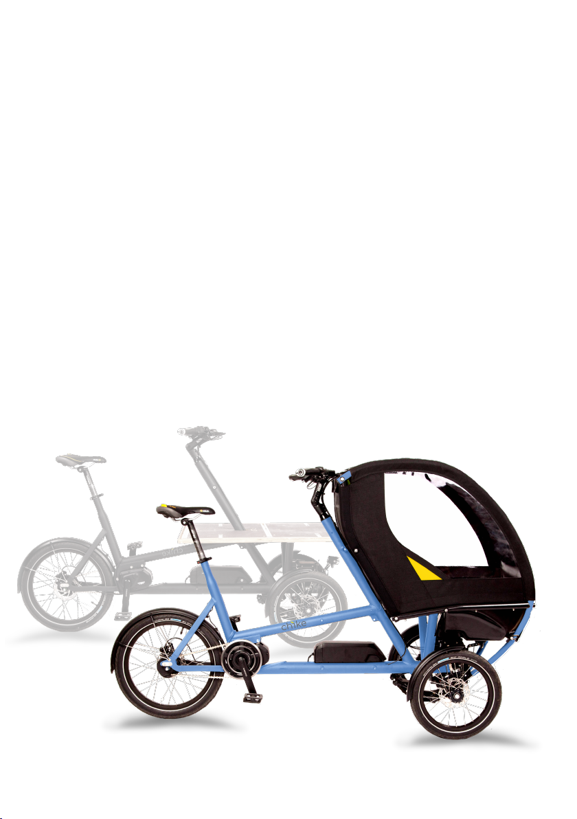
the cargobike
Operating Instructions
Page 2

Page 3

1st edition, 2017, english version
©2017 chike GmbH & Co.KG Printing errors, mistakes and
technical changes reserved
All product names mentioned in this manual are trademarks or
registered trademarks of the respective title holder.
The current version of this manual can be downloaded for
personal use in pdf format on http://chike.de
Printed on chlorine-free paper
iii
Page 4

iv
Page 5

Structure of manual
General information p.1
Before the first ride p.5
Before every ride p.11
After the last ride p.15
Operation p.17
Care and Maintenance p.29
A
B
C
D
E
F
Appendix p.45
v
G
Page 6

vi
Page 7

Contents
A. General information 1
ba . . . . . . . . . . . . . . . . 1
ba kids . . . . . . . . . . . . . 1
ba cargo . . . . . . . . . . . . 1
About this manual . . . . . . . . . . 1
Riding on public roads (Germany) . 2
Permissible loads . . . . . . . . . . 3
Intended Use . . . . . . . . . . . . 3
B. Before the first ride 5
Adjusting the riding position . . . . 5
Learning how to ride . . . . . . . . 6
For first owner . . . . . . . . . . . 8
C. Before every ride 11
Visual and functional checks . . . . . 11
Loading . . . . . . . . . . . . . . . 12
D. After the last ride 15
BatteryD . . . . . . . . . . . . . . . 15
Frame and bicycle components D . . 15
E. Operation 17
Brakes . . . . . . . . . . . . . . . . 17
Tilt lock . . . . . . . . . . . . . . . 18
Gear shift JN . . . . . . . . . . . . . 19
Gear shift D . . . . . . . . . . . . . 19
Cabin C . . . . . . . . . . . . . . 20
Adjusting the belt system . . . . . . 20
Buckling up of the children . . . . . 20
Closing the cabin . . . . . . . . . . 20
Load platform K . . . . . . . . . . 21
Load distribution and securing . . . 21
Wall . . . . . . . . . . . . . . . . . 21
Systainer mounting system . . . . . 21
Euroboxes for frame mount . . . . . 22
Assembly . . . . . . . . . . . . . . 22
Attaching the boxes . . . . . . . . . 22
Detaching the boxes . . . . . . . . . 22
Stem . . . . . . . . . . . . . . . . . 22
Electric drive system D . . . . . . . 23
Components . . . . . . . . . . . . 23
Attach and detach the cycle computer 23
Power on the drive system . . . . . 24
Charging the battery . . . . . . . . 25
Assist level . . . . . . . . . . . . . . 26
Gear shift . . . . . . . . . . . . . . 26
Walk assist mode . . . . . . . . . . 26
Traveling range . . . . . . . . . . . 26
Light system D . . . . . . . . . . . . 27
Light systemJN . . . . . . . . . . . . 27
Miscellaneous topics . . . . . . . . . 27
Fenders . . . . . . . . . . . . . . . 27
F. Care and Maintenance 29
Braking system . . . . . . . . . . . 29
Gear shift . . . . . . . . . . . . . . 30
Chassis . . . . . . . . . . . . . . . . 31
Wheels . . . . . . . . . . . . . . . 34
Cabin C . . . . . . . . . . . . . . 34
Transport platform K . . . . . . . 35
Chain . . . . . . . . . . . . . . . . 35
Lighting system . . . . . . . . . . . 37
Wear parts . . . . . . . . . . . . . 37
Spare parts . . . . . . . . . . . . . 37
Cleaning . . . . . . . . . . . . . . . 37
Pedelec variant D . . . . . . . . . . 38
Maintenance list . . . . . . . . . . . 39
ba -pass . . . . . . . . . . . . . 41
Inspection verification . . . . . . . . 42
G. Appendix 45
Tightening torques of certain screws 45
Technical specifications . . . . . . . 46
EC Declaration of Conformity D . . 48
vii
Page 8

viii
Page 9

A General information
ba
ba is a cutting edge compact cargo
bike for which driving pleasure, safety
and useful features are the first priorities.
The innovative design makes optimum
use of the available space. With a length
of less than 2m and a width of only
73cm, ba easily fits on narrow cycle
paths and passes all standard doors.
Nevertheless, it oers a lot of space
for anything you want to transport. The
tilting suspension technology makes the
ba extremely agile which is a great
benefit, especially in narrow down town
areas.
ba kids
Whether for the daily trip to the
kindergarten, going shopping with your
children or the weekend excursion
into nature, ba kids is the ideal
companion for you and your family!
Despite its small overall width of just 73
cm, ba ’s seat width of 70 cm oers
enough space for two larger children
without having to fight for every inch.
The cabin made of Cordura fabric
protects in any weather. Through the
large windows your children have a great
panoramic view. And through the small
window in the roof, you always have
them in view. The five-point belts oer
maximum safety and can be used flexibly
for a child in the middle or two children
next to each other.
A
ba cargo
Whether for business needs or private
use, ba cargo carries you and
your goods quickly to any destination.
Without a car. And also the annoying
search for parking space is avoided.
Despite its compact outer dimensions,
ba has a large loading capacity.
With a length of 90 cm and a width of
72 cm, the transport platform oers
plenty of space for everything you can
imagine to transport. Embedded into
the platform, airline rails serve as a fixing
point for straps to easily and securely fix
your freight. With the help of optional
walls the transport platform is quickly
transformed into a transport box with a
height of 35 cm and a loading capacity of
about 200 litres.
Thanks to its modular design, you can
easily convert your ba at a later
time. Whether from kids to cargo or
vice versa, chike adapts to your changing
life situation.
About this manual
The present operating instructions
ensures, that you are able to handle your
ba in a safe way. It was created with
the utmost care and handles all relevant
topics. Be sure that you also received
a copy of the more specific instruction
1
Page 10
A
manuals for brakes, shifters and drive
system released by the respective
component manufacturers. Please
also carefully read these additional
manuals as they explain the operation
and maintenance of the respective
components in detail.
If there are any further questions after
reading this manual or there is an issue
that is not covered in this manual, please
feel free to contact your local dealer
where you purchased your ba .
Please note the following points:
Read these operating instructions
carefully before using your ba for
the first time. Due to the innovative
technology of ba , even experienced
bicycle enthusiasts will find important
new information in this manual.
Dierent sections of this manual
are specific to certain model variants of
ba . These sections are marked as
follows:
D: Pedelec version only
JN: Non-electrical version only
C: Kids version only
K: Cargo version only
It is sucient to only read the sections
relevant to your variant.
Keep these operating instructions
in a safe place in order to have them at
hand if needed.
Provide these operating instructions
to every user of your ba .
Use section Inspection verification on
page 42 to document the services carried
out.
If you resell your ba , please
include these operating instructions.
For damages which occur because
these operating instructions were not
respected, chike GmbH & Co.KG will not
assume liability.
The latest version of this manual
can be found on the Internet at
http://chike.de in the download area.
In order to quickly identify important
information and potential dangers, these
are labeled in the text as follows:
This symbol highlights a
useful hint that to profit
even more from your
ba .
This symbol marks a
warning. Ignoring this
warning may damage your
ba or may cause minor injuries.
This symbol describes
a danger. Ignoring this
instruction can result in
severe damage to your ba and
serious injury or death to the driver
and passengers.
Riding on public roads (Germany)
While the pedelec variant is equipped
with a permanently mounted StVZO1compliant lighting system powered by
the motor battery, the non-motorized
version is delivered without a lighting
system. To be allowed to use your nonmotorized ba on public roads even
1
2
German road trac regulations
Page 11
in the dark, you have to equip it with
a lighting system. We recommend a
battery powered headlamp and a battery
powered tail light. Your dealer, where
you bought your ba , will be pleased
to help you in this regard.
The electrically assisted version of
your ba conforms to the European
pedelec norm EN 15194 (average
engine power <250W, maximum
assistance speed 25 km / h) and may
therefore be used like a normal bicycle
without insurance, driving license in
countries belonging to the EU (EU
directive 2002/24/EC). It may be
ridden on public roads according to
the trac rules applicable to bicycles.
Nevertheless please check, whether
there are additional restrictions applying
to your specific country. Your ba
dealer will assist you in this regard
Even if it is not obligatory
to wear a helmet, we
nevertheless recommend
that you always wear a helmet for
your own safety when riding your
ba .
Permissible loads
Your ba is designed for the following
maximum payloads:
maximum total weight 200kg
Payload cabin C 60kg
Payload transport box K 80kg
maximum rider weight 100kg
Payload Euro box 12kg
tare weight from 30kg
1
Please note that if permitted payload
and permitted driver weight are maxed
out, the permissible total weight would
be exceeded. Such a loading scenario is
therefore not allowed!
Exceeding the permitted
payloads can damage
your ba and cause
serious accidents. In addition to the
individual load limits, always respect
the permissible total weight!
Intended Use
ba cargo bikes are designed for use
on roads or paved roads. Driving on
rough terrain, driving on stairs or driving
over high curbs can cause severe damage
to your ba .
In the kids version, your ba is
designed to carry a maximum of two
children.
Make sure that the transported children
or loads are always properly secured.
In particular, make sure that your
children do not come into contact with
moving parts of your ba while riding.
Never leave your children unattended in
your ba kids.
The seating system of your ba kids
is suitable for children who are able to sit
upright unaided. Due to the suspension
and the tilt chassis, the forces acting on
the transported children are generally
small compared to transporting them in
a child trailer. ba can be retrofitted
with the baby supporters of common
child trailer manufacturers, so that even
2
smaller children are seated safely and
A
General information
1
each right and left
2
depending on features
3
Page 12

A
comfortably. Likewise, ba oers
a mounting adapter for MaxiCosi baby
carriers. If you have doubts about
whether your toddler can already be
transported in ba , please seek the
advice of your pediatrician.
Make sure that your children are
appropriately dressed to temperature
and feel comfortable during the ride.
Before each trip, make sure that you do
not exceed the maximum payload and
the maximum total weight (see section
Permissible loads p.3) .
When using your ba on public
roads, be sure to comply with all legal
obligations to be fullfilled.
Using your ba in poor visibility or in
the dark requires the use of an approved
lighting system.
Do not make any modifications to your
ba . Use only original replacement
parts and accessories.
All usage and maintenance instructions
described in this operating manual are
part of the intended use.
chike GmbH & Co. KG assumes no
liability or warranty if you use your
ba in any other way than its intended
use.
4
Page 13
B Before the first ride
Having received your ba , you will
undoubtedly be eager to try it out.
Before you go on public roads with
your ba , however, you should
first become familiar with its driving
characteristics. On the one hand, your
ba has a higher weight than a
common bicycle. On the other hand you
have to get used to sitting on a tricycle,
which nevertheless tilts and thus has
the driving dynamics of a two wheeled
bicycle. Like a bike, you have to balance
your chike in order to not roll over. After
a few minutes you get used to the new
exciting driving experience and will not
want to go back to your old bike.
If your respect the following tips and
guidelines, you will enjoy using your
ba and it will greatly simplify your
everyday life!
Please do not make your
first riding attempts on
frequented public roads in
order to avoid endangering yourself
and other road users. Do not
transport children in your ba
until you feel completely safe riding
your ba .
Adjusting the riding position
The right seating position is crucial for
a fatigue-free and ecient riding. The
seating position of your ba is set
up by adjusting the saddle height and
handlebar position. The saddle height is
adjustable by means of a quick-release
seat clamp. To adjust the stem, you need
a suitable Allen key. For stability reasons
a quick-release adjustable stem was not
an option. The various adjustments are
explained in more detail below.
Before riding your ba
, make sure that the quick
release seat clamp and
the bolts of the stem are properly
tightened! Check the tight fit of the
saddle and the handlebars!
Adjusting the saddle position
To properly adjust the height of the
saddle, put the right pedal into its lowest
position, have a seat on the saddle and
place the right heel on the right pedal.
In this position your leg should be fully
stretched. To adjust the saddle height,
you must first loosen the quick release
seat clamp. Then you can move the
saddle to the desired height. Make sure
that the seat post is not pulled out too
far There is a marking on the seat post,
which must not be visible but disappear
inside the seat tube of the frame. If there
is no marking, the seat post must be at
inserted into the seat tube at least 10
centimetres. After adjusting the seat
height, always check the tightness of the
seat post by trying to twist the saddle. If
it twists, the seat post clamp has to be
closed more tightly. If the seat post is
dicult to move in the seat tube when
the quick release is open, first try to
A
B
5
Page 14
A
B
clean the seat post and seat tube. If this
does not solve the problem, do not use
brute force, but contact your dealer.
The seat post must be
inserted at least to the
marking or 10cm into
the seat tube and the quick release
seat clamp must be firmly closed.
Otherwise, the seat post or the seat
tube may break.
Do not attach luggage
racks or panniers to your
seat post or seat tube
as they are not designed for this
purpose and could break in extreme
cases.
Adjusting the
handlebar position
Your ba is equipped with an angleadjustable stem. By changing the stem
angle, the distance between the saddle
and the handlebar can be adjusted (see
section Stem p.22). The factory-set
handlebar position should suit most
drivers. Not all possible positions are
permissible: adjusting the stem too much
to the front, may cause the handlebars to
collide with the cabin.
After each adjustment
of the handlebars, please
check that they have
enough clearance. Make sure that
the handlebars can be turned to the
left and right limit positions and that
this does not cause the shifter cables
and brake hoses to become pinched,
kinked or stretched!
Learning how to ride
The riding style of ba rather
corresponds to the balanced riding of a
two-wheeled bicycle than to riding a non
tilting tricycle. For your first tries, it is
best to choose an extensive area without
any obstacles until you learned to master
your ba safely.
Starting to ride
When you park your ba you lock
the tilting. This prevents ba from
tipping over to the right or left hand side
and thus corresponds in function to the
side stand of a common bicycle. Likewise,
the parking brake of the front wheels is
activated. This will prevent ba
rolling o on sloping terrain when parked.
To start riding first release the parking
brake (see section Brakes p.17) and the
tilt lock (see section Tilt lock p.18). Make
sure that the tilting is indeed released by
tilting your ba
right.
a little to the left and
Keep in mind, that your
ba can tilt sideways
and finally fall over if
the tilt mechanism is not locked.
When not riding, always try to hold
your ba in an upright, balanced
position. Otherwise higher forces
may be required to restore its
upright position, especially when
loaded.
To start riding,put one pedal in forward
position and place the corresponding
foot onto it. Then push o with the
other foot on the ground, to gain some
speed. Finally put the second foot on the
pedal and accelerate by pedaling. As with
a normal two-wheeled bike you need
from
6
Page 15
a certain speed to balance your ba
. The higher the speed, the easier it will
be to balance. Nevertheless, you should
make your first driving attempts within a
moderate speed range.
Stopping
Keep in mind that ba tilts
sideways and therefore needs to be
balanced like a two wheeled bicycle. To
stabilize the upright position of your
ba when stopping put one or both
feet from the pedals and place them
on the ground. If you stop for a long
time, it may be advantageous to block
the tilt mechanism (see section Tilt lock
p.18). To do this, your ba must be
in an upright position. With the tilt lock
engaged, you no longer have to actively
balance your ba . However, be sure
to release the tilt lock before starting to
ride again.
Braking
Your ba is equipped with high
quality hydraulic disc brakes. Please
check the correct functioning of the
brakes before each ride. The two front
brakes are operated simultaneously
with the left brake lever, the rear brake
is operated with the right brake lever.
Familiarize yourself with this mapping .
Further information about the braking
system can be found in section Brakes
p.17 and section Braking system p.29.
The braking power of
the disc brakes on your
ba might be much
higher than you are used to from
your previous bicycles. Therefore
please carefully test the brakes of
your ba before the first ride!
Please note that
unfavourable ground
conditions (wetness,
slipperiness, gravel, sand, ...) as
well as high loading can significantly
increase the braking distance!
During the braking process,
the discs and callipers heat
up. Do not touch the hot
parts because this can lead to severe
burns.
Parking
To park your ba , lock the tilt
mechanism (see section Tilt lock p.18)
and engage the parking brake (see
section Brakes p.17). By doing this your
ba can neither fall over nor roll
away. If possible, put your ba in a
place where it is protected from rain
and weather. Secure your ba with
a high-quality bicycle lock to achieve the
greatest possible protection against theft.
Parking D
In addition, remove the central
display unit from your ba (see
section Attach and detach the cycle
computer p.23). This prevents the use
of the electric drive by unauthorized
persons and the display unit from being
stolen.
Carrying children C
Your ba is designed to carry one
or two children. In order for these to be
transported safely, the following rules
must be observed
– Always buckle up your children
with the supplied seat belt system
(see section Buckling up of the
children p.20).
A
B
Before the first ride
7
Page 16
A
B
– Make sure to load your ba
such that it is optimally balanced:
if you only have one child with
you, use the middle seat, with
two children use the right and left
seats. The necessary repositioning
of the seat belt straps is quick and
easy (see section Adjusting the belt
system p.20)
Carrying loads K
The cargo version of your ba is
equipped with a load platform that
oers various load attachment options.
Take advantage of these possibilities
and secure the transported objects
against slipping or falling. The shift of
the center of gravity caused by slipping
of the load can lead to critical driving
situations. Store heavy objects as far back
as possible on the transport platform.
When distributing the load, make sure
that your ba is balanced as well as
possible.
Riding without
load or children
If you do not carry any loads with
your ba the front wheels are
relatively lightly loaded. As a result, when
cornering fast, your ba tends to
understeer. In extreme cases, the front
wheels lose grip which can lead to a loss
of control. In the unloaded state, drive
carefully and cautiously approach the
possible cornering speeds.
Passing curbs and stairs
If you push your ba over very high
curbs or steps, it may happen that the
lower end of the steering tube hits the
curb. This should absolutely be avoided
as the steering tube is not designed
for such impacts. The more loaded
your ba , the more critical it is.
Common curbs (up to approx. 14cm)
can be easily passed by your ba .
However high curbs at bus and tram
stops as well several steps in a row
(stairs) are more critical. In the latter
case, not only the lower end of the
steering tube but also the down tube
may collide with the upper edge of the
staircase. Therefore, carefully approach
the maximum step height that can be
passed without collision. If you have to
pass very high obstacles, such as stairs
in the hallway, it is helpful to increase
the ground clearance by lifting the rear
wheel.
Never drive hands-free and
always hold the handlebar
with both hands if possible.
Otherwise even small obstacles and
bumps can in extreme cases lead
to a loss of controll and to serious
accidents.
For first owner
Please observe the following measures
in order to enjoy your ba for a long
time.
Preparing the brakes
To ensure that the brand-new brake
pads can take full eect, they must be
initially prepared. For this purpose, some
full emergency braking operations must
be performed. The exact procedure
is described in section Braking system
p.30. Please follow these instructions to
ensure that the maximum braking power
is available in any dangerous situations
right from the start.
8
Page 17

Retightening the bolts
Due to the loads and movements
during driving, it may happen that
some screws of your newly assembled
ba settle and loosen. Your dealer
will check all bolts within the first
inspection and will retighten them with
the correct torque if necessary. Be
sure to seize this opportunity and have
the inspection documented in your
inspection certificates, p. 42. In later
operation, the screws usually do not
loosen anymore.
A
B
Before the first ride
9
Page 18

10
Page 19
C Before every ride
Visual and functional checks
Before each ride take a short time for
a visual and functional checks of your
ba . This will prevent you from using it
in an unsafe condition.
Many parts of your ba
are subject to heavy strains
and wear and tear. Any
kind of cracks, grooves or color
changes in highly stressed areas
indicate that the component is
damaged and should be replaced.
Brake system
Are the brake hoses not pinched or
bent?
Are there no leaks on the brake hoses?
Check the brakes by pressing the brake
levers. Even at full force it should not be
possible to pull the brake levers all the
way to the handlebar! With the brake
levers pulled, the rotation of the wheels
of your ba should be completely
locked! Check this by pulling your ba
forwards and backwards!
Tire pressure
Is the tire pressure of the front and rear
wheels sucient?
Operating your ba at
too low tire pressure can
lead to unsafe handling and
may damage the tires of your ba
.
Wheels
Are the front and rear wheels
tightly fixed to the frame?
Are there no cracked or loose spokes?
Are the tires undamaged and have
enough profile?
Seat post
Is the seat post inserted into the
seat tube at least to the mark, or at least
10centimetres?
Is the quick release on the seat tube
suciently tightened such that the saddle
does not rotate when a force is applied?
Stem
Are the screws which fix the angle
of the stem correctly tightened?
Is the stem adjusted in a way that there
is enough clearance for your steering
movements? Check this by turning the
handlebars to the right and left steering
limit (see also section Stem p.22)!
Tilt lock
Do all positions of the tilt-lock grip
shift work properly?
A
B
C
11
Page 20
A
B
C
Be sure to release the
tilt lock before driving!
Driving with a blocked
tilting mechanism can damage your
ba and will lead to uncontrollable
driving behaviour resulting in serious
accidents!
Screw connections
Make sure all screws are properly
tightened. Noise or unusual driving
behaviour may indicate loose screws
.
In the early stage after assembly, it is
possible that screw connections still
loosen. Your dealer will check this
within the first inspection and tighten the
screws to the correct tightening torques
if necessary. Afterwards the screws
should not loosen . If this happens
anyhow, please have the reason checked
by your dealer!
Loosened or insuciently
tightened screws can
damage your ba and
cause serious accidents!
cabin? Do the straps show no signs of
damage or wear?
Loading
The correct loading is a basis for a
comfortable and safe handling. On the
one hand the load securing is important.
On the other hand, care must be taken
to distribute children and loads as even
as possible, so that the ba does not
tilt too much on one side.
A maximum of two
children may be carried.
Children must always be
strapped and wear a bicycle helmet.
The carried children must not be
older than 7 years.
Pay attention to a
symmetrical distribution
of the loads. When
transporting a single child, it should
be strapped in the middle position.
Frame and chassis
Make sure that all frame and chassis parts
have no visible damage such as cracks
or bumps! If you notice any damage, let
your dealer check and repair your ba
before using it again.
Damaged components
can suddenly fail during
your ride and thus lead to
serious accidents!
Cabin
Is the fabric of the cabin undamaged?
Is the belt system properly fixed to the
12
When transporting loads
they must be secured by
straps or the like so that
they remain in place in the case of
extreme driving situations, such as an
emergency braking.
Page 21
The use of additional
transport devices, such
as rear wheel carriers or
child seats is not permitted unless
explicitly approved by ba .
Respect the maximum
payloads, see section
Permissible loads on page 3
A
B
C
Before every ride
13
Page 22

14
Page 23
D After the last ride
Your ba has been designed to last
for a long time. With good care it will
accompany your life for many years to
come. Nevertheless, the time will come
when a repair is no longer possible or
does not make sense from an economical
or ecological point of view. Then your
ba must be decommissioned and
properly disposed of, so that the raw
materials used can be returned to the
resource cycle.
BatteryD
Disused batteries must be collected
separately in accordance with European
Directive 2006/66 / EC and recycled
in an environmentally sound manner.
Your ba dealer will help you with the
proper disposal of your battery.
Never discard the battery
of your pedelec ba into
the household waste.
Frame and bicycle
components D
According to EU Directive 2012/19 /
EU, unusable electrical and electronic
equipment must be recycled in an
environmentally sound manner. This
includes the electronic components as
well as the drive unit of your ba .
Likewise, this directive also applies to
the battery charger. In Germany, you
can pass your ba at the end of its
life span free of charge to an appropriate
municipal collection point, where it is
properly disposed.
A
B
C
D
To ship the battery by
post parcel is usually not
allowed! If in doubt, ask
your shipping service provider!
15
Page 24

16
Page 25
E Operation
This chapter describes in detail how to
operate and use the various parts of your
ba .
Brakes
ba is equipped with high quality
hydraulic disc brakes on all three wheels.
The right and left front disc brakes are
operated together with the brake lever
on the left hand side of the handlebar
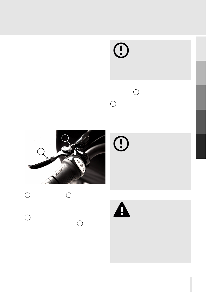
(see fig. 1, p. 17). The front disc brakes
have a locking function. To activate
2
1
Figure 1. : Parking brake
1 : Brake lever 2 : Locking lever
Always activate the parking
brake when parking your
ba . Otherwise, it might
unintentionally roll away on sloping
ground and subsequently cause
accidents and damage.
To release the parking brake, first pull the
brake lever 1 as far as possible to the
handlebar. This relieves the locking lever
2 so that it can be pushed back inwards
with relatively little force.
The rear disc brake is operated with the
brake lever on the right hand side of the
handlebar.
The most powerful braking
eect is achieved by the
front brakes. For this
reason the front brakes should
be use with preference! However,
avoid locking up the front wheels
as this will make you loose control
over your ba and may lead to
accidents.
A
B
C
D
E
the parking brake pull the brake lever
1 as far as possible to the handlebars.
Then pull the locking lever 2 outwards.
Check that the front wheels are actually
locked by pushing your ba forward
and backward.
On very long steep
descents with high load,
your brakes can overheat
due to the permanently applied high
braking power. Overheating can lead
to a sudden total of the brakes. To
prevent overheating, do not let the
brakes grind permanently, but brake
in intervals. Make stopovers to allow
the brakes to cool down.
17
Page 26
A
B
C
D
E
Tilt lock
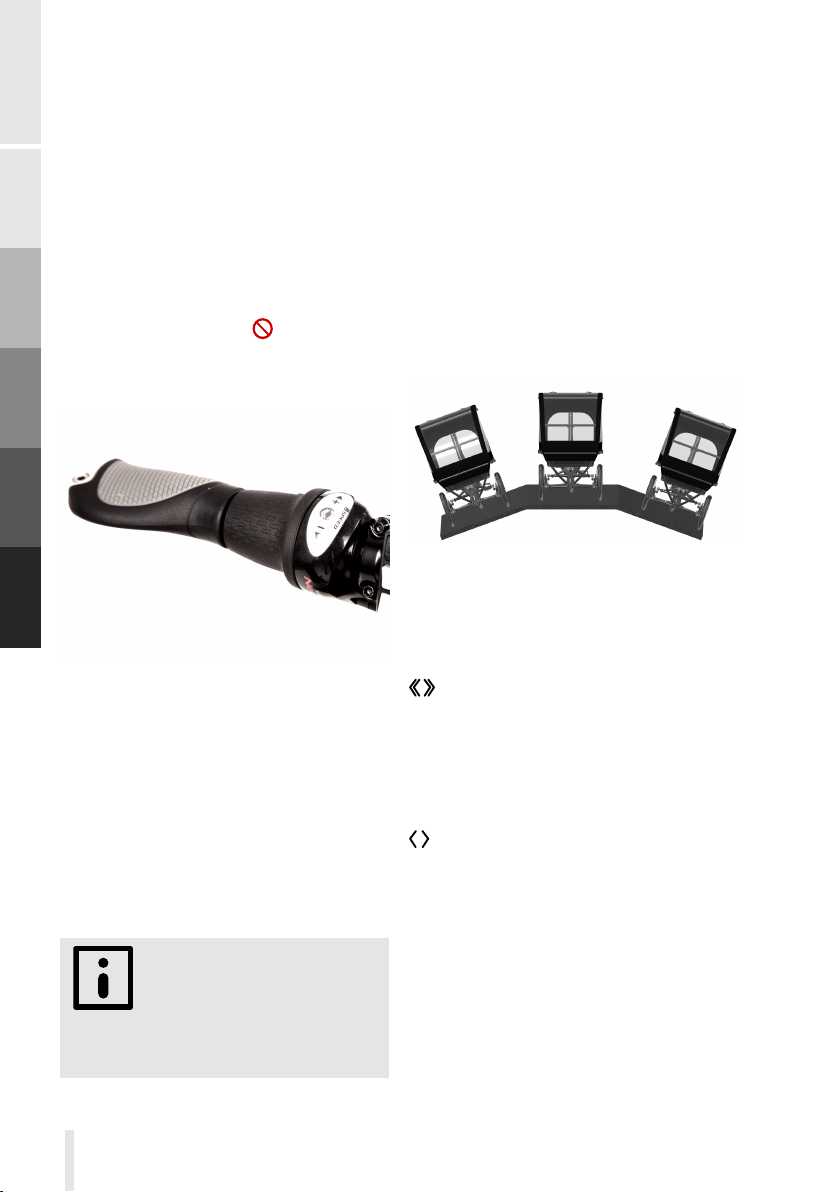
Your ba comes with a tilt adjustment
system that has three levels of tilt control.
The levels can be selected using the
grip shift lever on the left side of the
handlebar (see fig. 2, p. 18). The grip
shift lever has 7 or 8 indexed positions,
however only three of which have a
function assigned to. The intermediate
non functional shifting positions are
indicated by the symbol . This symbol
may only be shortly visible while changing
the tilt adjustment levels. Changing the
If you experience a high resistance when
trying to twist the grip shift lever in order
to change the tilt control level, most
probably your ba is not properly
oriented. Do not apply brute force to
the grip shift lever, but try to find the
proper orientation of your ba by
slightly tilting it to the right and left,
simultaneously applying a moderate
twistintg force to the grip shift lever.
High actuating forces may reduce the
life time of the grip shift lever or even
lead to damage
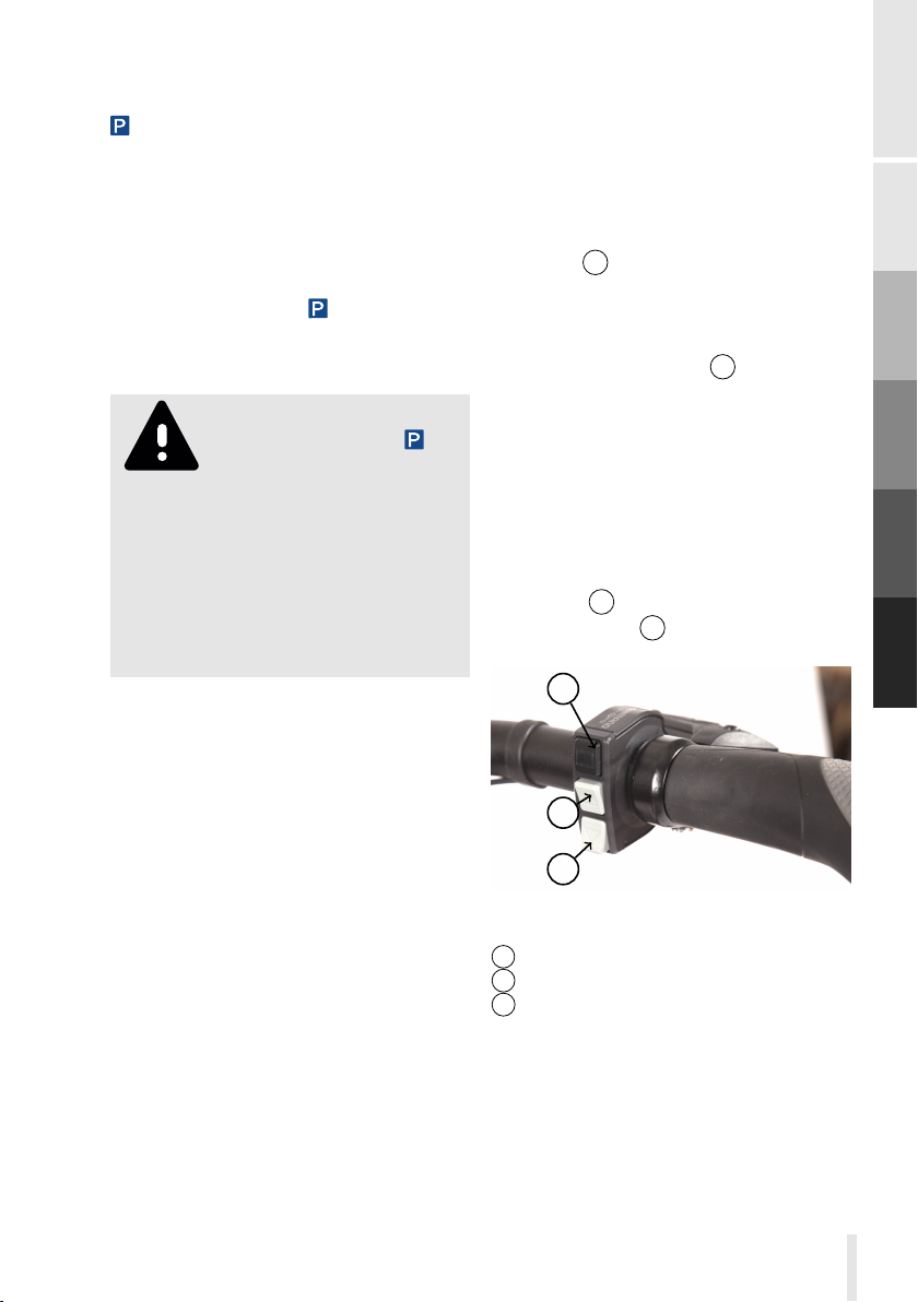
Figure 3. : Perpendicular orientation to
change tilt control levels.
Figure 2. : Grip shift tilt lock
various tilt control levels is only possible
if ba is oriented perpedicular to the
ground (see fig. 3, p. 18). If for example
the ground is sloping to the left hand side,
please tilt your ba to the left hand
side as well in order to change the tilt
control levels.
Before changing tilt control
levels, orient your ba
perpendicular to the
ground. Otherwise it is impossible to
change the tilt control levels.
18
completely free tilting. ba can be
tilted without any aligning torque up to
its maximum tilt angle (around ± 21°).
This tilt control level mostly corresponds
to the riding characteristics of a common
two wheeled bicycle.
Using this tilt control level, ba is
still able to tilt around. 21° to each side,
however with increasing tilt angle you will
experience an increasing aligning torque,
which pushes ba into its upright
position. This level is especially suited
when transporting high loads with ba
. Some people may also find it more easy
to do their first riding attempts on ba
using this level. The choice between
completely free tilting and tilting with
Page 27
alignment torque is often purely a matter
of taste.
locks the tilting mechanism in the
upright position. This level is intended
for wheeling or parking your ba . It is
also helpful for longer stops, e.g. at trac
lights, as you no longer have to actively
balance out your ba when the tilting
is locked. To park your ba , switch
the tilt control level to and engage the
parking brake (see section Brakes p.17)
Never ride with engaged
tilting lock out (Level ).
If the tilting is locked, it
is no longer possible, to safely turn
into corners . More over, riding with
locked tilting mechanism may damage
the frame and suspension. Before
starting to ride, please check, that
the tilting is not locked by slightly
tilting your ba to both sides.
Gear shift D
The pedelec version of your ba is
equipped with a electrically operated
DI2 8-gear internally geared hub by
Shimano. Shifting gears is done with
the switch at the right hand side of the
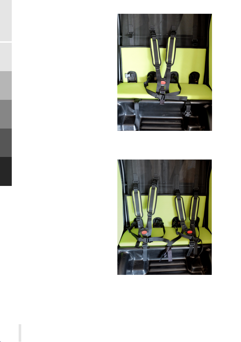
handlebar 5 , fig. 8, p. 24 and fig. 4,
p. 19. There are two gear shifting modes,
automatic shifting and manual shifting. To
change between automatic and manual
shifting, press the button1. The chosen
mode is shown in the central display.
In mode automatic the proper gear is
chosen automatically based on various
parameters like speed and cadence.
In mode manual the gears are chosen
by the rider. Also in automatic mode,
you can shift to a higher or lower gear
manually. To choose a lower gear press
the button 3 , to choose a higher gear,
press the button 2 .
1
A
B
C
D
E
Operation
Gear shift JN
Your ba is equipped with an 8speed internally geared hub by Shimano.
Changing gears is done with the
RapidFire lever located on the ride hand
side of the handlebar.
To change to a higher gear press the
lever which is facing to you with your
thumb.
To change to a lower gear pull the lever
which is facing away from you with your
index finger.
2
3
Figure 4. : Switching Gears Shimano
STEPS Di2
1 : Mode switch
2 : Switch up-shift
3 : Switch down-shift
19
Page 28
A
B
C
D
E
Cabin C
The cabin of the kids version is designed
and optimized to carry children.
However, it is also possible to transport
shopping bags or beverage crates in
the footwell In that case, appropriately
secure the load against unintended
movements.
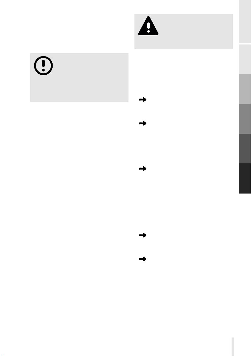
Adjusting the belt system
In order to have optimal driving
characteristics a balanced load
distribution is important. Therefore,
when transporting a single child, please
use the central seating position. The
cabin is equipped with a five point
harness. The various straps are attached
to the cabin by quick release buckles.
Use these buckles to adjust the harness
from the central position (one child) to
the left and right position (two children).
Buckling up of the children
First you have to adapt the shoulder
straps to the height of your child. To
this end move the upper buckles of
the shoulder straps into a position
approximately 3cm above the shoulder
of your sitting child. Next, position
the 3 point buckle between the legs of
your child and attach the corresponding
buckles of the shoulder straps to it. Then
tighten the shoulder straps. Finally put
the waist belt around the waist of your
child, close the buckles and tighten the
belt.
Figure 5. : Harness for one child
Closing the cabin The cabin is
closed by pulling the left and right zip all
the way down. Then the lower part of
the top is fixed to the cabin by clipping
the rubber straps over the corresponding
20
Figure 6. : Harness for two children
Page 29
pins. The top is equipped with an
elastic window and a fly screen. In good
weather you can open the window
separately and fix in in a convoluted state
to the top.
Never transport children
or adult persons on the
cargo platform. It is not
intended for this purpose.
When transporting
children at least the fly
screen has to be always
closed when riding in order to avoid
stirred up small objects to harm your
children's eyes.
Load platform K
The cargo version of ba provides
a platform, large enough to transport
four Euro-boxes of size 30cmx40cm
or two Euro-boxes of size 30cmx40cm
and one Euro-box of size 60cmx40cm,
respectively. In order to securely attach
your load to the platform, it is equipped
with three Airline rails, which serve to
mount various fastening elements. An
easy to mount wall is also available,
transforming the platform into a box
of size 90cm x 70cm. Finally there are
fixation elements to easily place and fix
Systainers onto the platform.
Load distribution and securing In order to have the most
easily controllable handling it is important
to place heavy loads as centred as
possible and as far back on the platform
as possible. Additionally, care has to be
taken to properly fix the loads onto the
platform or inside the box. To this end
use straps fixed to the Airline rails.
Wall To transport loose items, like
shopping bags, a wall is available, which
is easy to mount without any tools.
The wall is attached to the platform by
performing the following steps:
First make sure that all four door
bolts embedded into the platform
are in open position.
Then position the front and rear
wall with the coarse side facing
inwards into the grooves on the
front and rear side of the platform.
Try to position the walls as centred
as possible.
Next position the left side wall
with the rough side facing inwards
into the respective groove on the
platform. Keep the wall slightly
tilted outwards on the upper side
and pay attention that the hooks
of the front and rear wall slide into
the respective recesses of the side
wall.
Push down the side wall as far as
possible and close both door bolts
on the left hand side.
Mounting the right side wall is
done in the same way .
Systainer mounting system
Systainers can be easily attached to
the platform with the help of some
plastic fasteners. These fasteners are
plugged into the respective holes on
the transport platform and prevent the
Systainers from sliding on the platform.
A
B
C
D
E
Operation
21
Page 30
To finally fix the Systainers, they are
tightened onto t the platform with straps
attached to the Airline rails.
the frame.
Stem
A
B
C
D
E
Euroboxes for frame mount
The optionally available Euroboxes of
size 300mm x 400mm x 270mm provide
additional storage space of about 50l. To
use the boxes mounting bolts have to be
mounted to the frame. The Euroboxes
are then attached to your ba with an
easy to use toolless quick fix system.
Assembly In case you ordered the
Euroboxes together with your ba
the mounting bolts are already installed.
However, if you order the boxes
afterwards, please respect the installation
instructions which are provided with the
boxes.
Attaching the boxes Move the
boxes sideways to the frame such that
the recesses of the mounting rails on the
box match the mounting bolts attached
to the frame. Then slightly press the box
against the frame and move it forward (in
direction of riding, until the locking plate
snaps into place. Check that the box is
securely fixed by pushing it backwards.
Please observe, that the right and left box
are dierent. The locking plate always
has to point to the rear.
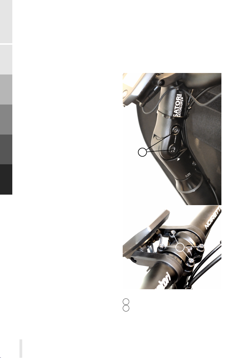
Your ba has an angle-adjustable
stem.
11
2222
Detaching the boxes Pull the
locking plate as far as possible outwards
(towards the box) and push the box
forward (in direction of riding) until it
is released and can be moved away from
22
Figure 7. : Stem
: Bolts angle adjustment
1
2 : Bolts handlebar clamp bracket
Page 31
Loosen the angle-adjustment bolts 1
two to three turns to adjust the angle
of the stem. This allows to adapt the
distance between saddle and handlebars
to your needs. Finally tighten the bolts
1
with a torque of 14-15 Nm.
Changing the angle of the stem in
generally also requires to rotate the
handlebars. To this end loosen the bolts
of the handlebar clamp bracket 2 and
rotate the handlebars to the desired
position. Take care that the handlebars
are centered and that the clamping
bracket of the stem is positioned in the
clamping area of the handlebars. Then
tighten the bolts 2 with a torque of 5-6
Nm.
After adjusting the stem and handlebars
make sure that the handlebars can be
turned to the right and left steering limit
(about 40° in each direction). To this end
place your hands on the handlebar grips
and put your fingers around the brake
levers. This way you make sure that in
all steering positions, there is enough
clearance for your hands. Please also
check, that in all steering positions the
brake hoses, shift cables and electric
wires (pedelec version) are neither
kinked nor stressed nor clamped.
Electric drive system D
The pedelec version of ba is
equipped with the electric drive system
STEPS by Shimano. The motor has a
power of 250 Watt and assists you when
pedalling up to a maximum speed of 25
km/h.
The internal gear hub of your pedelec
ba is electrically shifted. the following
sections provide a short overview of the
electric drive system.
Please also carefully read
the original instructions of
your Shimano STEPS E6000
drive system which are provided with
your ba . They provide you the
necessary information to safely use
your pedelec- ba .
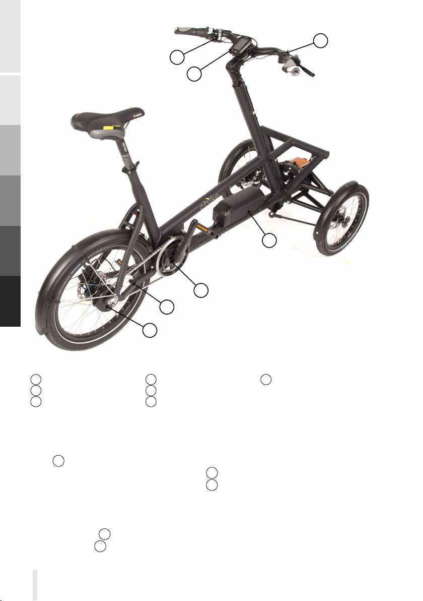
Components The electric drive
system consists of several components
(fig. 8, p. 24).
The drive unit or motor is a so called
mid-mount motor ( 2 , fig. 8, p. 24). It is
positioned at the crank set.
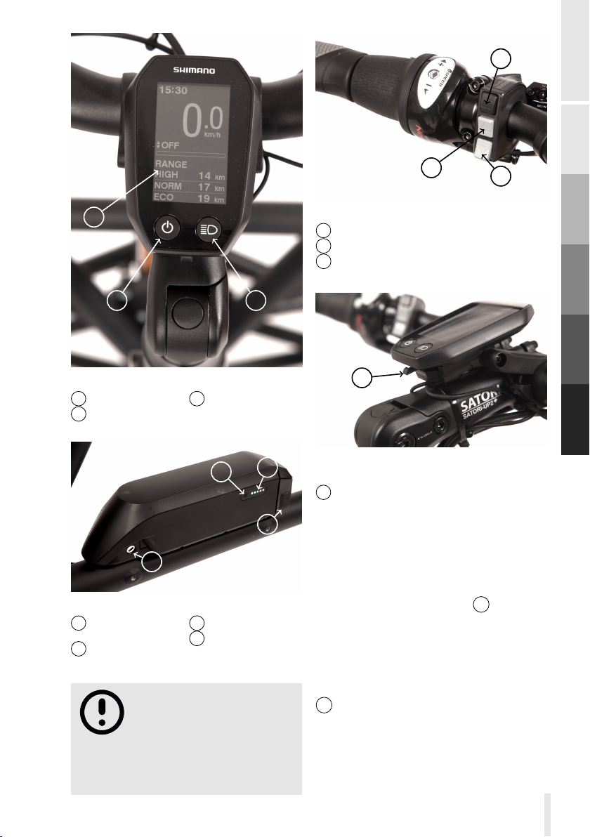
The cycle computer( 3 , fig. 8, p. 24
and fig. 9, p. 25) is located in the centre
of the handlebars at the stem. It displays
various information like speed, remaining
battery range etc. and serves to switch
on the electric system as well as the
lighting
The battery ( 1 , fig. 8, p. 24 and
fig. 10, p. 25) is mounted on the down
tube.
There are two switches ( 4 and5,
fig. 8, p. 24 and fig. 11, p. 25) located
at the right and left hand side of the
handlebars. With the switch on the left
hand side you can choose the assist level
and change the display mode. The switch
on the right hand side is used to shift
gears and to switch between manual
gear shift mode and automatic gear shift
mode.
Attach and detach the cycle computer To attach the cycle
computer slide it backwards onto the
A
B
C
D
E
Operation
23
Page 32
A
B
C
D
E
5
4
3
1
2
6
7
Figure 8. : Pedelec components
: Battery
1
2 : Mid-mounted drive unit
: cycle computer
3
bracket until it snaps in. To detach the
cycle computer slightly push the release
lever1, fig. 12, p. 25 downwards and
then shift the display forward until it is
released from the bracket.
4 : Assist switch
5 : Gear shift switch
: Speed sensor
6
Power on the drive system
To switch the drive system on and o,
press the button 1 , fig. 9, p. 25 on the
cycle computer 3 , fig. 8, p. 24 and
24
7 : Motor unit Alfine Di2
keep pressing it for about 2 seconds.
Alternatively, the system can be switched
on and o in the same way using button
3 , fig. 10, p. 25 located on the battery
1 , fig. 8, p. 24.
Page 33
1
3
1
Figure 9. : Cycle computer
1 : Power switch
2 : Light switch
2
Figure 10. : Battery
1 : Charge
connector
2 : Locking
Do not apply any torque
to the crank shaft when
powering on the drive
system. Otherwise the motor may
start to run, which most probably is
not desired in this situation.
3 : Display area
3 : Power button
4 : Battery level
2
3
indication
2
Figure 11. : Assist switch
1 : Display mode
2 : Increase assist level
3 : Decrease assist level
3
B
C
D
A
1
E
4
1
Figure 12. : Attaching the cycle
computer
1 : Release lever
Charging the battery To
charge the battery plug the charging
cable of the included battery charger into
the into the charging socket 1 , fig. 10,
p. 25 at the battery mount. If you do
not have the opportunity to charge the
battery attached to your ba , detach
the battery. To this end put the provided
key into the lock at the battery mount
2 , fig. 10, p. 25. Turn the key counter
clockwise as far as possible and slide the
front end of the battery to the left until it
is completely released.
Operation
25
Page 34
A
B
C
D
E
Please write down the
key number of the battery
lock in the respective line
of your ba passport on page
41. The number is imprinted on the
key. Having the number you can
contact your dealer to apply for a
replacement key in case of loss.
When detached from ba the battery
can be charged using the battery charger
with the supplied plug adapter. More
details are provided in the original
instructions provided by Shimano which
came with your ba .
The used batteries
store a lot of energy.
Observe all operating
and warning instructions of the
enclosed instructions of the battery
manufacturer to avoid any danger.
Pay particular attention to the
instructions on the label of the
supplied charger.
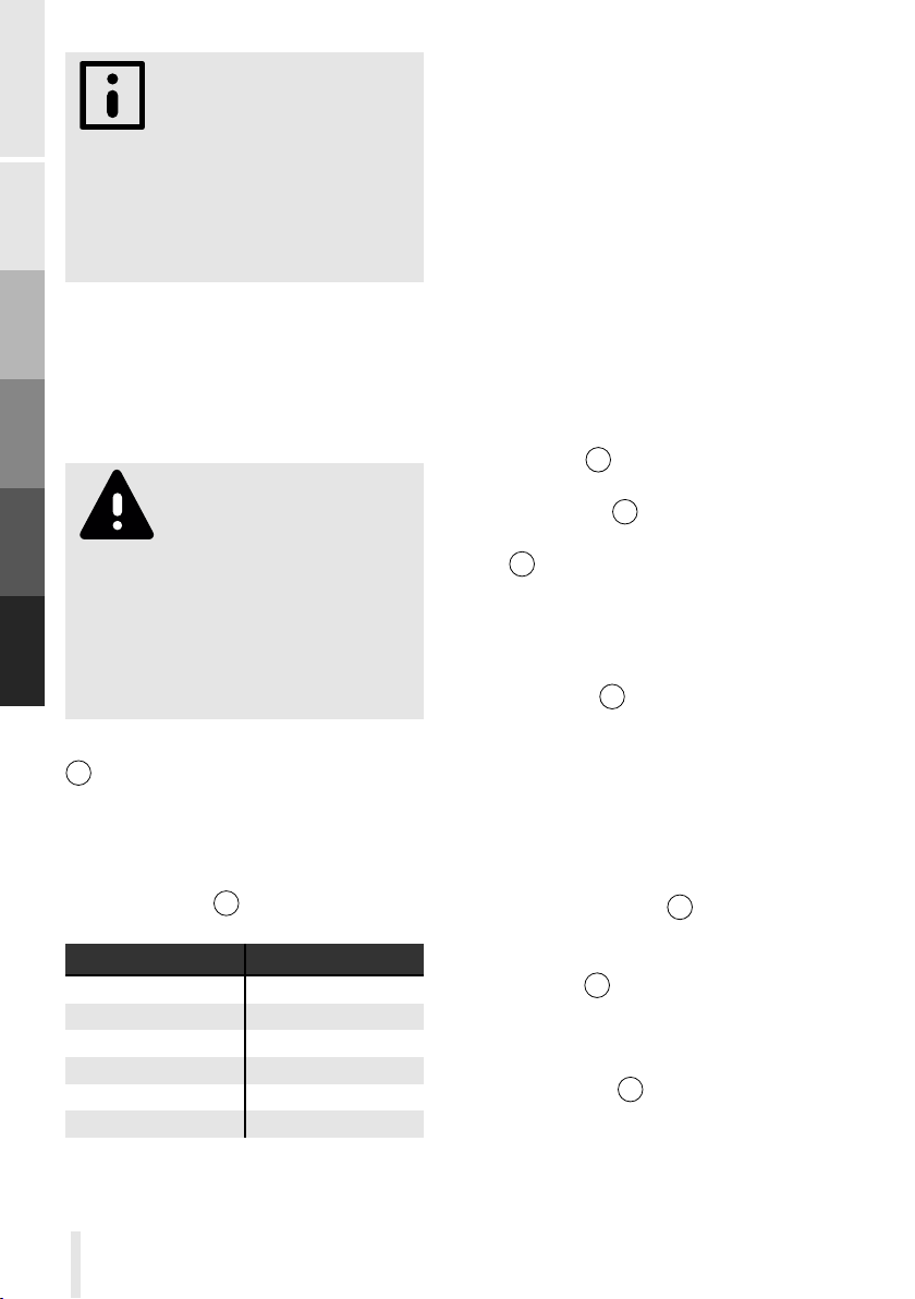
The battery has a battery level indication
4 , fig. 10, p. 25 consisting of five
lamps. When the system it powered
on the lamps indicate the battery
level. When the system is powered
o or the battery is released first
press the button 3 , fig. 10, p. 25 to
switch on the battery level indication
Battery level
0-20%
20-40%
40-60%
60-80%
80-100%
100%
Various other flashing and lighting
patterns indicate possible malfunction.
Display
◦ ◦ ◦ ◦ ◦
• ◦ ◦ ◦ ◦
• • ◦ ◦ ◦
• • • ◦ ◦
• • • • ◦
• • • • •
Details can be found in the enclosed
instructions of the drive system.
Assist level The electric drive
system provides four assist levels, OFF,
ECO, NORMAL and HIGH. In mode ECO
the pedalling support by the electric
motor is lowest while in mode HIGH
you get maximal support. In mode
the electric assistance is switched o,
however the system is still running, i.e.
the display shows information, the lights
can be switched on and the electric gear
shift is working. You can switch between
the various assist levels using the buttons
on the shift unit 4 , fig. 8, p. 24 located
at the left hand side of the handlebars.
Pressing the button 2 , fig. 11, p. 25
increases the assist mode, pressing
button 3 , fig. 11, p. 25 decreases the
assist mode finally turning o the electric
assistance.
OFF
Gear shift Shifting the gears is done
with the shift unit 5 , fig. 8, p. 24 located
on the right hand side of the handlebars.
Details can be found in section section
Gear shift D p.19.
Walk assist mode To activate
the walk assist mode, first turn o the
electric assistance. (assist mode OFF).
Then pressing the button 3 , fig. 11,
p. 25 for a few seconds activates the
walk assist mode. In walk assist mode,
pressing button3, fig. 11, p. 25 turns
on the motor, without having to apply
a torque to the crank set, thus assisting
you to walk your ba at low speeds.
Pressing the button 2 , fig. 11, p. 25
exits the walk assist mode.
26
Page 35
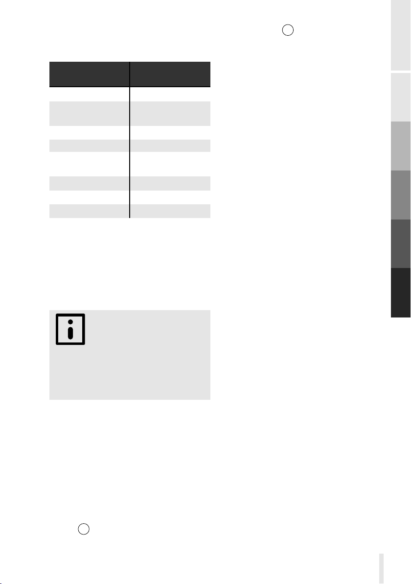
Traveling range The traveling
range of a fully charged battery depends
on various factors:
decreased
travelling range
high total weight low total weight
frequent decelerating
and accelerating
high assist level
headwind tailwind
Uneven or soft
ground
hilly terrain
low temperatures
high speed
Due to the higher weight and drag of
your ba
bicycles the travelling ranges shown
on the cycling computer are to be
taken with care. In general, the actual
achievable travelling range is below these
indications.
some shorter trips, such that you
are not caught o guard by an empty
battery on a long trip far away from
home .
compared to common
Get familiar with the
achievable travelling ranges
of your ba during
increased
travelling range
steady speed
low assist level
paved road
flat terrain
high temperatures
low speed
cycle computer 3 , fig. 8, p. 24.
Light systemJN
The non electric version of ba
does not come with any light system
as standard. In order to be allowed to
use it in dark on public roads you have
to install an appropriate light system. We
recommend a battery powered front and
tail light.
Miscellaneous topics
Fenders Your ba is equipped
with front and rear fenders as standard.
The front fenders are exposed to high
forces due to the single sided mounting.
Please do not attach any additional parts
like lights to the fenders, as their weight
will further increase the loads on the
fenders, which finally may lead to failure
of the fender stays.
A
B
C
D
E
Operation
Light system D
The pedelec version of ba is
equipped with a high quality light system,
consisting of a front light, a tail light and
a rear reflector. It is in accordance with
German legal trac regulation. To turn
the light system on and o press the
button 2 , fig. 9, p. 25 locate on the
27
Page 36

28
Page 37
Care and
F
To keep your ba in perfect condition,
some care and maintenance is necessary.
This will guarantee a safe and long-lasting
usage and preserves the joy of using your
ba for many years .
Only carry out
maintenance work for
which you have the
necessary tools and expertise! If
in doubt, have the maintenance
carried out by your ba dealer!
Before carrying out any
maintenance work, always
remove the battery first,
unless it is explicitly required for the
maintenance work carried out!
If you manipulate the
electrical system, your
ba will no longer be
safe to use. Using your ba with
manipulated electric controls on
public roads might be a criminal
oence.
Maintenance
brakes regularly for wear. If the wear
limit is reached, the brake pads and,
if necessary, the brake disc must be
replaced immediately. In particular, if you
observe a decreasing braking power or
scratching noise when braking, the brake
pads must be checked and renewed if
necessary. Depending on the load and
driving style, the disc brakes wear o at
dierent rates. Therefore, no general
rule can be given after which distance
a control and/or replacements should
be carried out. It is better to check the
condition of the brake pads more often
than too rarely.
Falling below the wear limit
can lead to total failure of
your brake system.
Be sure to read the
operating instructions
provided by the brake
manufacturer! If the operating
instructions are not available, contact
your dealer.
Changing brake pads
For changing the brake pads, follow the
instructions of the brake manufacturer.
A
B
C
D
E
F
Braking system
The brakes are subjected to heavy
friction during each braking process. This
causes signs of wear both on the brake
pads and on the brake discs. Check the
Only use original spare
parts from the brake
manufacturer. If in doubt,
let your dealer service the brakes of
your ba .
29
Page 38
A
B
C
D
E
F
Changing brake disk
If the wear limit of the brake disc has
been reached, please contact your dealer.
He will professionally replace the brake
discs.
More extensive
maintenance work on
your brake system should
only be carried out by qualified
persons. Improper maintenance can
cause leaks or trapped air, which can
lead to failure of the brake system.
Bleeding the brake
If your brake no longer has a defined
pressure point and feels spongy, there
may be air in the hydraulic hoses. In that
case the brake has to be bled. The exact
procedure of bleeding is described in the
instructions of the brake manufacturer.
As properly bleeding the brakes requires
some experience, it is best to ask your
dealer to do this.
When servicing and
cleaning your ba ,
make sure that no cleaning
agents or oil gets in contact with
the brake discs or brake pads as this
would strongly decrease the braking
power or even lead to a total failure
of the brakes.
Initially preparing the brake
After replacing the brake pads or
brake disc, the brake has to be initially
prepared to regain full braking power.
Proceed as follows: Drive slowly approx.
50m with slightly applied brakes. As a
result, the temperature of the brake
pads and brake disc are increased.
Then accelerate to about 25km / h and
brake with maximum braking power to
standstill. Make sure that you do not
endanger yourself or other road users
during this process. Perform this process
up to 10 times consecutively. After a few
braking manoeuvres you should notice
a significant improvement of the braking
power.
Do not change the route
of the hydraulic hoses
of your brake system.
Incorrect routing may cause the
hydraulic lines to be pinched or
stretched, which can lead to leaks
and failure of the brake system.
Regularly check the brake
lines for kinks or leaks.
Damaged or broken brake
lines can lead to a failure of the brake
system and subsequently to serious
accidents!
Never operate the brake
levers with the wheels
removed. As a result, the
brake pads would close and the
brake disc can no longer be slid in
the caliper.
Gear shift
Your ba is equipped with a Shimano
Alfine 8-speed internal gear hub. A
major advantage of the internal gear
hub is the fact that the moving parts
are encapsulated inside the hub and
30
Page 39
thus protected from dirt. Compared
to a derailleur system much of the
maintenance tasks therefore are omitted.
In the case of unprecise gear change,
strange noise or slippage of the chain
please let your dealer check the hub!
Carefully read the
instruction manual by
the manufacturer of the
hub which was supplied with your
ba .
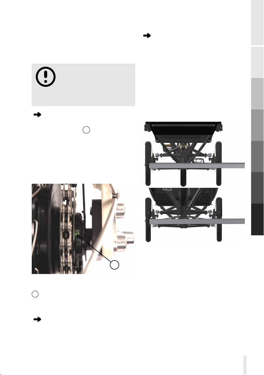
Adjusting the gears JN
Switch to 4th gear. In this gear, the
two green markings1, fig. 13, p. 31
on the hub must be aligned to each
other. If this is not the case, turn the
adjusting screw on the handle. Turning
the adjusting screw clockwise moves
the outer marking to the front, turning
counterclockwise moves it to the rear.
Chassis
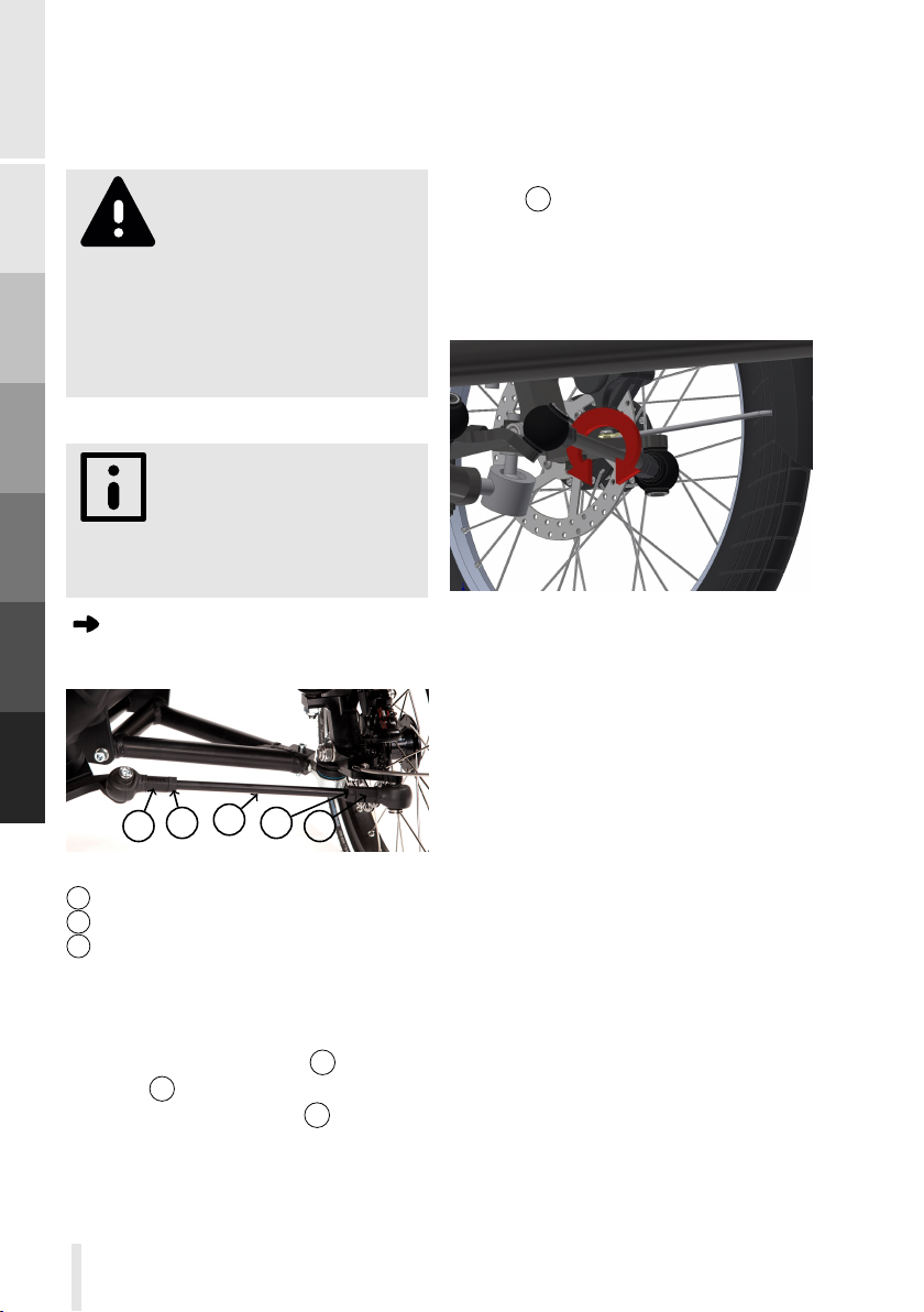
Checking the toe angle
The toe angle is set correctly when the
two front wheels are parallel and in
forward direction when steering forward.
If the toe angle is set correctly once, as
it is during assembly, it normally should
not change over time. If the toe angle
changes noticeably this is an indication
of damage to the chassis. In this case,
please have your ba checked by
your dealer. The toe angle is checked by
A
B
C
D
E
1
Figure 13. : Adjusting the Alfine 8 gear
hub
: Markings
1
Maintenance
Larger maintenance work on the hub
should be done exclusively by your
dealer or a trained person.
F
Care and Maintenance
Figure 14. : Checking the toe angle
measuring the distance between the two
front wheels in the front and at the back.
To this end first rotate the handlebars,
such that both wheels are facing forward.
As a reference point for measuring use
either the rim shoulder or a groove on
the tire. Use the same reference points
for both the distance measurement in the
front and at the back.
If the measured distance is the same at
31
Page 40
A
B
the front and at the rear, the toe angle is
set correctly. If the two distances dier
by more than 2mm, the toe angle must
be readjusted.
A sudden change of the
toe angle is an indication
that some component of
the chassis was deformed and thus
might fail in further use. Therefore, if
the toe angle is misaligned, let your
ba be checked by your dealer
before further use.
moves rotates the front wheel to the
left (inwards) a clockwise rotation to
the right (outwards). When the wheel
is properly aligned the tie rod has to
be locked. To this end tighten the outer
lock nut 2 with 3Nm. Make sure, that
the tie rod does not rotate w.r.t. the
tie rod end while tightening the lock
nut, as this would again misalign the toe
angle. Having locked the outer tie rod
C
D
E
F
A wrong toe angle implies
higher rolling resistance
and higher tire wear. Please
check regularly if the toe angle is still
set correctly.
Adjusting the toe angle
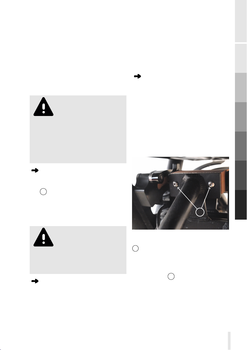
To adjust the toe angle, first lock out
3
2
1
Figure 15. : Adjusting the toe angle
1 : Tie rod ends
: lock nut
2
: tie rod
3
the tilt (see section Tilt lock p.18) and
fix the handlebars in forward position.
Then loosen both lock nuts 2 of the tie
rod ends 1 of the right tie rod fig. 15,
p. 32.Now turn the tie rod3, until
the right front wheel points exactly into
forward direction. A counterclockwise
rotation (when looking outwards)
2
1
Figure 16. : Adjusting the angle
between both tie rod ends
end, hand tighten the inner tie rod end’s
lock nut and rotate the tie rod as far as
possible forward and backward fig. 16,
p. 32. This assures that the right and
left tie rod end have the correct angle
(about. 30°) w.r.t. each other. Now fix
the inner tie rod end by tightening the
lock nut with 3Nm. make sure that the
angle between both tie rod ends does
not change while tightening the lock nut.
Now the left tie rod has to be adjusted.
To this end loosen both lock nuts of the
left tie rod. To properly adjust the toe
angle, measure the distance between
the rim shoulder of the left and right
front wheel, once at the foremost
position of the wheels and once at the
rearmost position. The dierence should
be at most 2mm. If the dierence is
32
Page 41
bigger, it has to be compensated by
turning the left tie rod. Rotating the tie
rod counterclockwise (when looking
outwards) increases the distance at
the back and decreases the distance in
the front and vice versa for a clockwise
rotation. If both distances are equal
the toe angle is correctly adjusted.
Tighten the lock nuts in the same way
as described for the right tie rod.
As adjusting the toe angle
needs some experience
and the proper tools
it is better to let your dealer
do this. Damaged tie rods or
unproperly mounted and locked
tie rod ends may render your ba
uncontrollable, possibly leading to
severe accidents.
Checking the tie rod ends
Please regularly check the wear of the tie
rod ends. To this end move the tie rod
end 1 , fig. 15, p. 32 up and down with
moderate force. If there is a play of more
than 2mm in this direction, the tie rod
end has to be replaced. Please contact
your ba dealer.
replaced. Nevertheless, check at regular
intervals, whether the suspension
elements shows any signs of wear, in
particular whether the connection
between the elastomer and the metal
plates comes o. If this is the case, the
suspension element must be replaced
immediately.
Replacing the
suspension element
The suspension element covers the
entire range of payloads from empty
run to the maximum permissible load.
An adaptation is therefore usually not
required. The damper element needs to
be replaced only in case of damage. To
replace the damper element, it is best to
fix your ba in a work stand. Lock out
the tilting (see section Tilt lock p.18).
11
A
B
C
D
E
F
Care and Maintenance
Worn-out tie rod ends
negatively eect the
steering characteristics.
Therefore please have the tie rod
ends replaced in case of wear as
soon as possible.
Checking the
suspension element
ba is equipped with a sturdy
elastomer suspension element that
requires no special care and normally
does not wear out or need to be
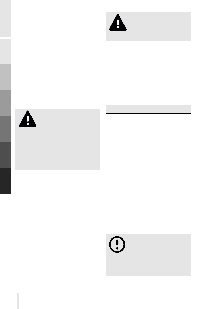
Figure 17. : Replacing the suspension
element
: Fixing screws suspension element
1
Then loosen the two screws on the
right hand side1, fig. 17, p. 33 and
the two screws on the left hand sides,
which fix the suspension element to the
upper A-arms. Please hold the respective
wheel while loosening the second screw
on each side and then gently let the
wheel come down up to the stop. Now
33
Page 42
A
B
C
D
E
F
the suspension element is ready to be
removed. To this end bend the left and
right hand side of the suspension element
upwards and then remove the element.
The child version especially has very little
clearance above the suspension element.
Here it is best to unlock the tilting and
to rotate the suspension element and
the central part to which it is attached as
far as possible to one side to get more
clearance. Mounting the new suspension
element is done analogously in reverse
order. Tighten the screws with a torque
of 2Nm.
Make sure that there are
no external forces on the
A-arms while working on
the suspension element, as there is
a risk of crushing when the A-arms
move. Since replacing the suspension
element requires expertise and the
right tool, you should leave this task
to your dealer.
Wheels
Your ba is equipped with high-quality
wheels that are maintenance-free when
used properly. Nevertheless, check
regularly whether your wheels have a
radial or axial run-out, no spokes are
damaged and the spoke tension is not
too low. To check the spoke tension,
press together two spokes at a time of
each side of the wheel with your thumb
and forefinger. If individual spokes feel
loose or if you notice dierent spoke
tensions, please let the wheel be checked
by your dealer.
Damaged spokes must be
replaced immediately as
they may lead to a total
failure of the wheel.
Regularly check the tire for damage to
the tread or side surfaces. If damage
is visible, the tire must be replaced
immediately.
As soon as the green or blue puncture
protection on the tread of the tire is
visible, the wear limit is reached. At the
latest then the tire must be replaced.
The following tire types are permitted:
Front wheel Rear wheel
Schwalbe Big Apple
16x2.00, ETRTO
50-305
Schwalbe Big Apple
Plus 20x2.15,
ETRTO 55-406
Cabin C
The cabin is made of a sturdy aluminium
construction covered with high-quality
fabrics and a plastic tub in the seat and
floor area. The materials are chosen so
that longevity is granted even without
further care. If sand, small stones or
the like accumulate in the plastic tub
or on the cushions,it is best to remove
them with a common vacuum cleaner.
Staining of the fabric cover or the plastic
tub can be removed with a soft sponge
and lukewarm water.
Only use water and, if
necessary, mild soap to
clean the cabin. Do not
use any aggressive cleaning agents
as these could damage the fabric
covering.
34
Page 43
Chain
Regularly check that the
belt system is properly
attached to the cabin and
in impeccable condition. Damaged
straps or buckles must be replaced
immediately! An improperly fastened
or worn belt system may break,
loose or rupture in the event of an
impact, resulting in serious injury to
the child!
Regularly check that the
plastic tub has no cracks or
other damage! A damaged
tub must be replaced immediately!
From time to time, check that the screws
connecting the various cabin tubes have
not loosened and, if necessary, retighten
them to the specified torques (see
section Tightening torques of certain screws
p.<Pgrf2>). Under no circumstances
should you exceed the specified torque,
as otherwise the pipes may be deformed.
Transport platform K
The transport platform consists of
waterproof glued phenolic resin
coated plywood. At the cutting, drilling
and milling surfaces, the plate needs
additional protection against penetrating
moisture. Upon delivery, such protection
is applied. However, due to mechanical
stress and wear the sealing properties
may be lost over time. Therefore, from
time to time, check that the edge sealing
is still in good condition and renew the
sealing if necessary.
The chain of a cargo bike is exposed to
high forces and therefore requires regular
care and maintenance. Dirty chains are
subject to increased wear.
Just as important as a well-cleaned
and lubricated chain is the right chain
tension. An incorrect chain tension has
negative eects on the wear out of
other parts such as sprocket or chain
wheel. Furthermore, the chain can jump
o the sprocket or chainwheel due to
insucient chain tension. Furthermore,
the right chain tension is important for
a precise shifting of the gear hub. Check
the chain tension regularly and adjust it if
necessary.
Due to the loads occurring during
pedalling, the chain lengthens with time.
Since the elongated chain links no longer
optimally fit the teeth of the chainwheel
and sprocket, these parts are subject
to increased wear. Therefore, the chain
must be replaced in good time. If the
sprockets and / or the chainwheel
are already worn out, it is advisable to
replace them together with the chain.
Cleaning
To clean the chain, first remove
dirt and lubricants with a dry cloth. Now
apply a suitable chain lubricant and let it
act for a few minutes. Excess lubricant is
then removed with a cloth.
When lubricating the chain,
make sure that no lubricant
gets in contact with the
brake discs or brake pads and the
tires as this would greatly reduce the
braking power and the road grip of
the tires.
A
B
C
D
E
F
Care and Maintenance
35
Page 44
When servicing the
chain, always inspect the
chainwheel and sprocket
and clean them if necessary.
wheel is properly centred.
A
B
C
D
E
F
Checking the chain tension
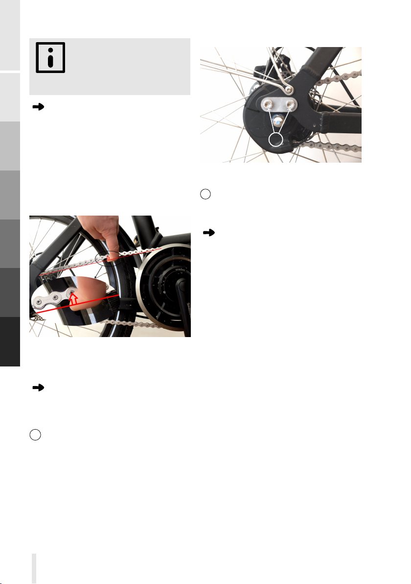
To check the chain tension, pull the
upper chain strand up in the middle,
fig. 18, p. 36. The deflection of the chain,
symbolized by the red arrow, should be
about 1cm to 1.5cm. Otherwise, the
chain tension must be readjusted. Too
high chain tension is just as bad as a too
low chain tension!
Figure 18. : Checking the chain tension
Adjusting the chain tension
First loosen the two screws that hold
the right and the two screws that hold
the left rear fork end slider to the frame
1
, fig. 19, p. 36. This allows the rear
fork end slider to move horizontally
together with the rear wheel. If you now
pull the rear wheel backwards, the chain
tension increases. The correct chain
tension is achieved when the chain can
be compressed in the middle by about
2cm. When tightening the screws of
the drop out sliders, make sure that the
11
Figure 19. : Moving the rear fork end
slider
1 : rear fork end slider screws
Checking chain elongation
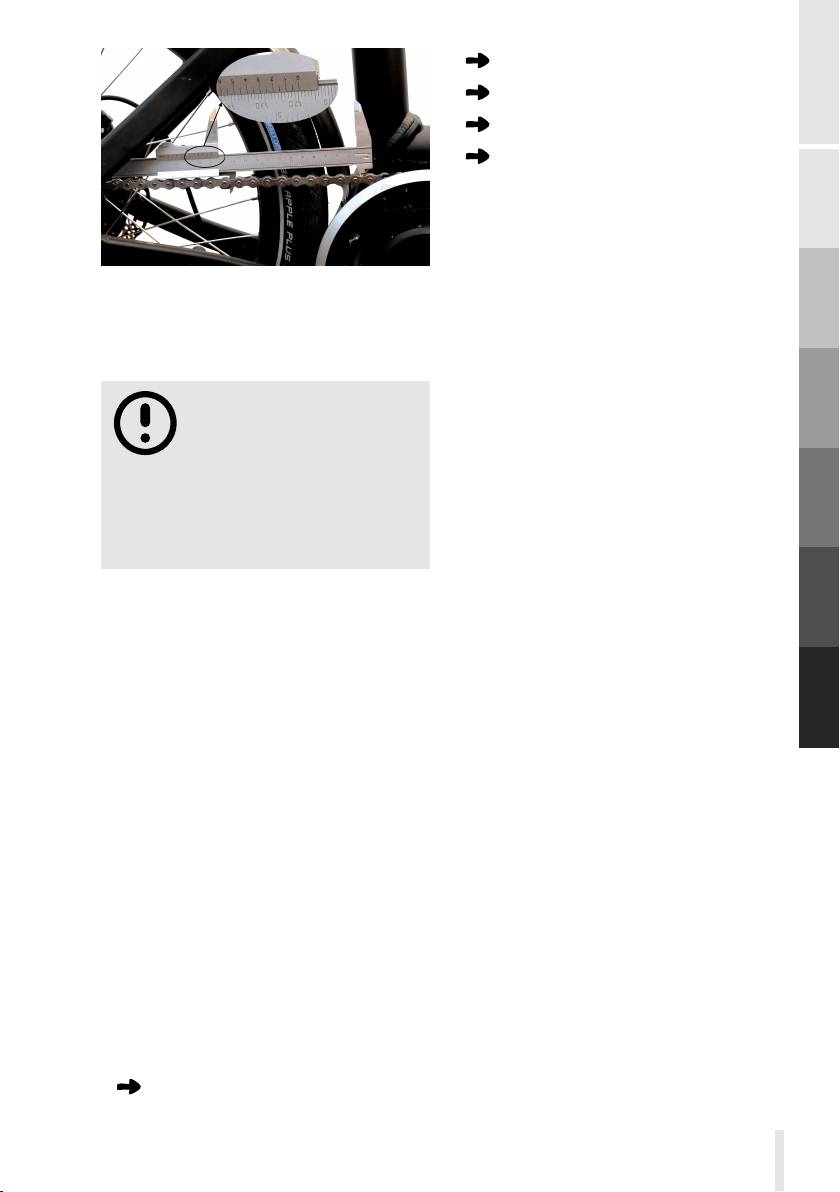
We recommend to check the chain
length every 1000km. The elongation
of the chain can be determined with
a standard calliper. Set the calliper to
118mm and put the two ends for the
outer measurement in the free space
between two rolls of the tensioned chain,
most simply at the upper chain strand
fig. 20, p. 37. Then slide the calliper apart
until it touches the rollers. Now read o
the distance. The 119.6mm measured
in fig. 20, p. 37 correspond to a new
chain. Up to a distance of 120.25mm
the elongation of the chain is still in
the tolerance range. If the distance is
bigger, it is time to replace the chain.
Chain wear gauges are also commercially
available, making the determination of
chain elongation even easier. If you do
not want to do the check yourself, your
ba dealer will be happy to assist you
in checking and possibly changing the
chain.
36
Page 45
Brake pads
Chain, chain ring and rear sprocket
Battery D
Tie rod ends
These parts must be replaced when
reaching the wear limit.
A
Figure 20. : Determination of chain
elongation
The replacement of the
chain requires special tools
and expertise and should
therefore be done by your dealer.
Worn sprockets or chain wheels
should also be replaced at the same
time if necessary.
Lighting system
Check regularly that the head light and
the tail light of your ba are working.
Make sure that the headlight is properly
adjusted such that you do not blind
approaching trac or pedestrians.
Wear parts
Most components of your ba last a
whole life cycle. However, some parts
are subject to wear and must be regularly
replaced and renewed. The achievable
service life of these parts depends on
the specific use of your ba and the
proper maintenance. The wear parts are
Tires
Spare parts
If any component of your ba is
damaged, you get the respective
replacement parts from your dealer.
Cleaning
Regularly clean your ba . Road
salt in winter can especially lead to
increased corrosion if it is not removed
immediately. Just use a soft cloth or
sponge and pure water. Do not use
a pressure blaster because due to the
high pressure water will pass into sealed
areas and can cause damage there. In
general, you do not need any additional
cleaning products. For heavy grease or
oil stains, you can use a standard cleaning
product for bicycles. Make sure that the
chosen product does not attack the paint
surfaces.
Use the cleaning process to examine
your ba for possible damage such as
deeper scratches, bumps, cracks, etc. If
you notice any damage, please contact
your dealer!
After cleaning your ba and drying o
the remaining water, we recommend that
you preserve your ba . To this end
appropriate bicycle care products can
be used. Follow the instructions of the
B
C
D
E
F
Care and Maintenance
37
Page 46

chosen product.
A
B
C
D
E
Pedelec variant
conductive and causes short circuits if it
gets into places where it is not intended
to be. Although the pedelec drive
system of your ba is designed to
withstand heavy rain, it is not completely
waterproof. Therefore, when cleaning
with water, make sure that no running
water reaches the components of the
drive system. Individual water splashes
are harmless. In particular, do not
submerge your ba for washing.
Ideally, use only a damp cloth around
the Pedelec components. Again, do not
use any aggressive cleaners, as they may
possibly damage the insulation of the
cables and cause short circuits.
D
Water is
F
38
Page 47

Maintenance list
A
B
C
D
E
The following table lists the necessary maintenance procedures for
your ba . Obviously you can always hand over maintenance work,
which in principle can be carried out by yourself, to your dealer. The
individual maintenance procedures are described in detail in chapter
F
Care and Maintenance
39
Page 48
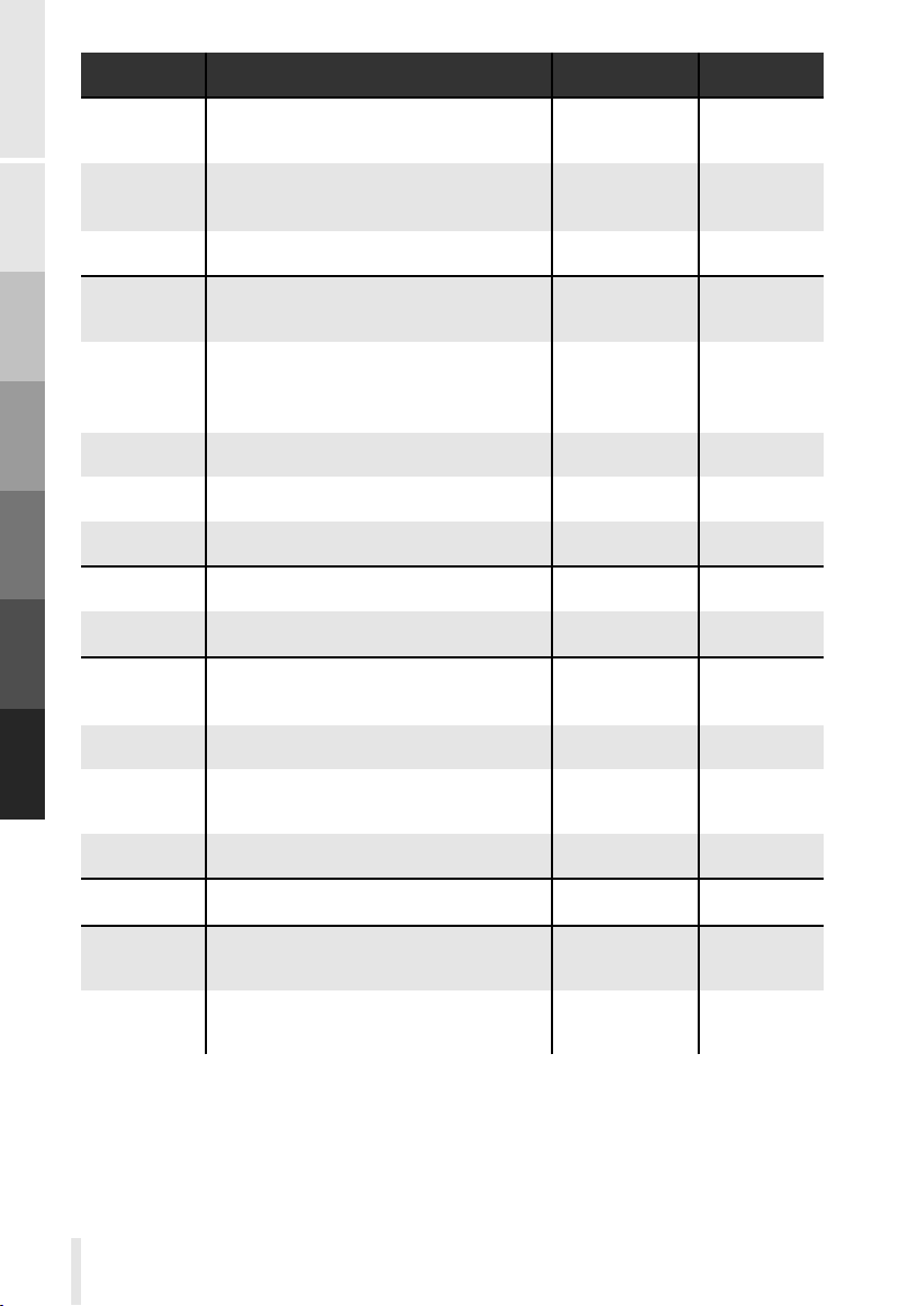
Part
Maintenance
Interval
By
A
B
C
D
E
F.
Tires
brakes
chain
chassis
Checking tire pressure
Checking running surface and side walls
for damage and sucient profile
Changing tires if necessary
Checking hydraulic hoses for damage,
brake test
Checking brake pads
Changing brake pads if necessary
Changing brake disk if necessary
bleeding brakes
Lubricate and check for wear
changing
Checking toe angle
Adjusting the toe angle
before every
ride
before every
ride
before every
ride
see section
Braking system
p.29
if necessary
monthly
if necessary
see section
Chassis p.31
if necessary
user
user
user
user
user
user
dealer
dealer
user
dealer
user
dealer
F
Checking tie rod ends for play
Changing tie rod ends if necessary
Wheels
Steering Checking that there is no play
40
Checking spoke tension and run-out
Checking the handlebars for damage
before every
ride
monthly
before every
ride
before every
ride
user
dealer
user
user
user
Page 49

ba -pass
Model:
2D 2C 2K
Frame colour:
2black 2ivory 2light blue 2orange
2light green 2Special colour . . . . . . . . . . . . . . . .
Cushion colour C:
2red 2orange 2light green
2Special colour . . . . . . . . . . . . . . . .
Frame Number:
Key number D:
Delivery Date
Dealer stamp and signature
A
B
C
D
E
F
Care and Maintenance
41
Page 50
Inspection verification
A
B
C
D
E
1. Inspection
After 300km or three months
from the date of purchase
Job number:
Date:
Stamp and signature of the dealer:
2. Inspection
At the latest 2000km or one
year from the date of purchase
Job number:
Replaced or repaired parts, comments
Replaced or repaired parts, comments
F
Date:
Stamp and signature of the dealer:
42
Page 51
3rd Inspection
After 4000km or two from the
date of purchase
Job number:
Replaced or repaired parts, comments
Date:
Stamp and signature of the dealer:
4. Inspection
At the latest 6000km or three
years from the date of purchase
Job number:
Date:
Stamp and signature of the dealer:
Replaced or repaired parts, comments
A
B
C
D
E
F
Care and Maintenance
43
Page 52
5. Inspection
At the latest 8000km or four
years from the date of purchase
Job number:
Replaced or repaired parts, comments
A
B
C
D
E
F
Date:
Stamp and signature of the dealer:
6. Inspection
At the latest 10000km or five
years from the date of purchase
Job number:
Date:
Stamp and signature of the dealer:
Replaced or repaired parts, comments
44
Page 53
G Appendix
Tightening torques of certain screws
During assembly, the screws of your ba were tightened with the correct
torques. Nevertheless, it may happen that certain screws have to be retightened
due to setting processes. This is done by your dealer within the first inspection.
Other screws must be loosened and tightened during maintenance or adjustment
procedures. Always observe the tightening torques given in the table and never
exceed them.
Part
Axle nut front wheels Wrench 18 50 Nm
Axle nut rear wheel Alfine
Fixing of the inner axles of the
A-arms
Ball joint to wheel carrier
Ball joint to A-armr Allen key 5
Fixing cabin to frame front
bottom
Fixing cabin to frame side
Pedal to crank Wrench 15
Angle adjustment stem Allen key 5
Handlebar to stem
Clamping stem to head tube
Bolt load carrier
Lock nut tie rod ends Wrench 15
Screws damper mounting
Connecting screws for cabin
tubes
Tie rod ends to steering tube and
wheel carrier
Rear fork end slider
Key
Wrench 15
Allen key 6
Wrench 18 40 Nm
Allen key 6
Allen key 5
Allen key 4
Allen key 5
Wrench 18
Torx 25 3 Nm
Allen key 4
Allen key 5
Allen key 6
Tightening
torque
40 Nm
30 Nm
12 Nm
20 Nm
12 Nm
35-40 Nm
14-15 Nm
5-6 Nm
9-10 Nm
12 Nm
3 Nm
5 Nm
12 Nm
18 Nm
Screws
retention
-
-
-
-
-
-
-
-
-
-
-
medium
strength
-
-
-
medium
strength
-
A
B
C
D
E
F
G
45
Page 54

Technical specifications
A
B
C
D
E
total weight 29 - 40kg
length 185cm - 192cm
width 74cm
height 110cm - 118cm
1
1
1
F
G
46
1
depending on variant and features
Page 55

A
B
C
D
E
F
47
G
Appendix
Page 56
EC Declaration of Conformity D
1/1
EG Konformitätserklärung
gemäß der Maschinenrichtlinie 2006/42/EG vom
17.05.2006, Anhang II A
Hiermit erklären wir, dass die nachstehend bezeichneten Produkte in ihrer Konzeption und
Bauart sowie in den von uns in Verkehr gebrachten Ausführungen den Anforderungen der
Maschinenrichtlinie 2006/42/EG entsprechen. Bei einer mit uns nicht abgestimmten
Änderung des Produktes verliert diese Erklärung ihre Gültigkeit.
Hersteller
chike GmbH & Co.KG Tel.: +49 221 20464354
Neusserstr. 407 Fax: +49 221 94647113
50733 Köln e-mail: [email protected]
Deutschland web: chike.de
Produkte
Produktnummer
Bezeichnung
Antriebssystem
Baujahr
CHKE-NF-0000-A0000M
chike e-kids
Shimano STEPS E6000
Akku Shimano KBTE6010LC
Ladegerät Shimano KECE60001
2017/2018
CHKE-NF-0001-A0000M
chike e-cargo
2017/2018
Es wird Übereinstimmung mit folgenden Richtlinien/Bestimmungen erklärt:
2014/30/EU Elektromagnetische Verträglichkeit (EMV)
2014/35/EU Niederspannungs-Richtlinie
Titel der angewandten harmonisierten Normen:
DIN EN 15194:2015-06 soweit anwendbar, insbesondere die Abschnitte 4.3.7.4, 4.3.7.5,
4.3.7.6, DIN EN ISO 4210
Ort/Datum
Köln, 01.02.2018
Bevollmächtigter zur Ausstellung dieser Erklärung:
Manuel Prager, Geschäftsführer chike GmbH & Co.KG
Neusserstr. 407, 50733 Köln
Unterschrift
Manuel Prager
A
B
C
D
E
F
G
48
Page 57

A
B
C
D
E
F
49
G
Appendix
Page 58

Page 59

Page 60
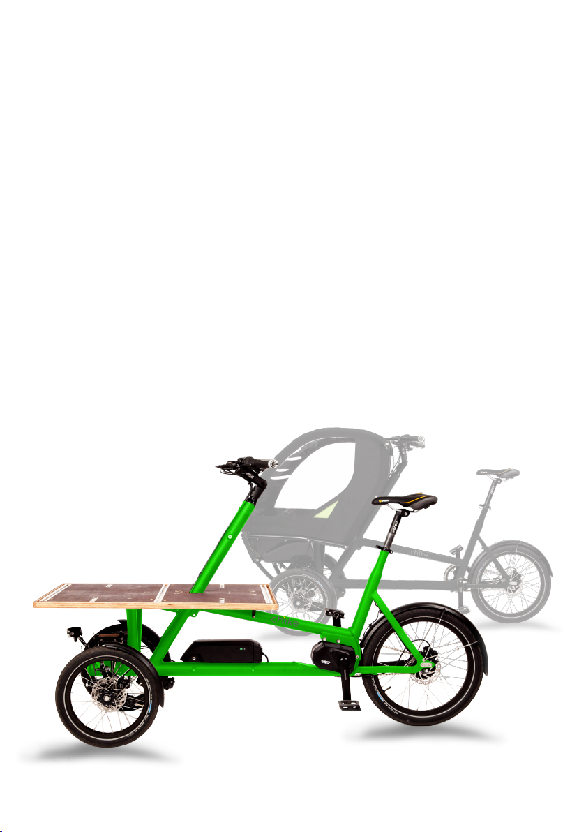
 Loading...