

CHIEF PAC-170 Installation Instructions Manual
INSTALLATION INSTRUCTIONS
Small Flat Panel Bracket – Floor Stand
(PAC-170)
The PAC-170 Floor Stand assembly is compatible with
small flat panels and other products and accessories
offered by Chief.
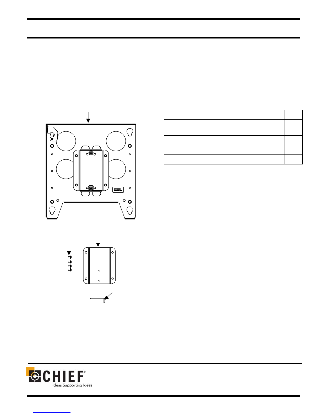
PARTS
10
PARTS LIST
Unpack the shipping carton and check for the contents
listed in Table 1 and shown in Figure 1.
Table 1. Parts List
REF DESCRIPTION QTY
10 FRONT BRACKET, floor stand
(with attached mounting plate)
20 SCREW, button head cap, 5/16-18 x ½” 4
30 BACK BRACKET, floor stand 1
40 ALLEN KEY, 3/16” 1
1
20
Figure 1. Parts
30
40
CHIEF MANUFACTURING INC. 8807-000049 (Rev. A)
1-800-582-6480 952-894-6280 FAX 952-894-6918 ©2005 Chief Manufacturing
8401 EAGLE CREEK PARKWAY, STE. 700 www.chiefmfg.com
SAVAGE, MINNESOTA 55378 USA 09/05
Installation Instructions PAC-170
t
play
TOOLS REQUIRED FOR INSTALLATION
• 3/16” Allen Key (provided)
NOTE: Other tools may be required depending on your
method of installation.
10
Floor Stand Pos
INSTALLATION
To install the PAC-170 bracket assembly, do the
following:
30
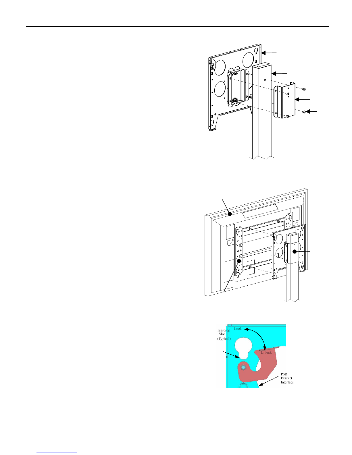
Attach PAC-170 to Floor Stand
NOTE: Make sure that mounting plate faces toward the
front of the floor stand before attaching the
PAC-170 to the floor stand.
1. Attach front bracket (10) and back bracket (30) to
the floor stand post (see Figure 2) using four
5/16-18 x ½” button head cap screws (20).
2. Adjust the PAC-170 to the desired height on the
floor stand.
3. Tighten the screws.
Mount the Display
1. Make sure power is not supplied (turned off) to the
display and the locking device is in the unlocked
(down) position (see Figure 4) before attempting to
mount the display.
2. Following the instructions for mounting the PSB
interface bracket of your specific plasma display
panel, install the mounting bracket on your plasma
display panel.
20
Figure 2. Attach PAC-170 to Floor Stand
Dis
PAC-170
3. With an assistant, slide the display down over the
mounting plate on the PAC-170. Make sure buttons
of PSB interface bracket fully engage all teardrop
slots on the mounting plate.
4. Secure the mounting bracket to the PAC-170 by
completely engaging the locking device
(see Figure 4).
WARNING: Make sure the locking device securing the
display is completely engaged at all times
except when removing or installing the
display.
NOTE: A padlock may be used on the locking device for
increased security.
5. Connect and secure power/audio/video cables (not
shown).
2
PSB Bracket Interface
Figure 3. Mount the Display
Figure 4. Locking Device
 Loading...