

Page 1
INSTALLATION INSTRUCTIONS
Q
PAC-140
Q-CLAMP
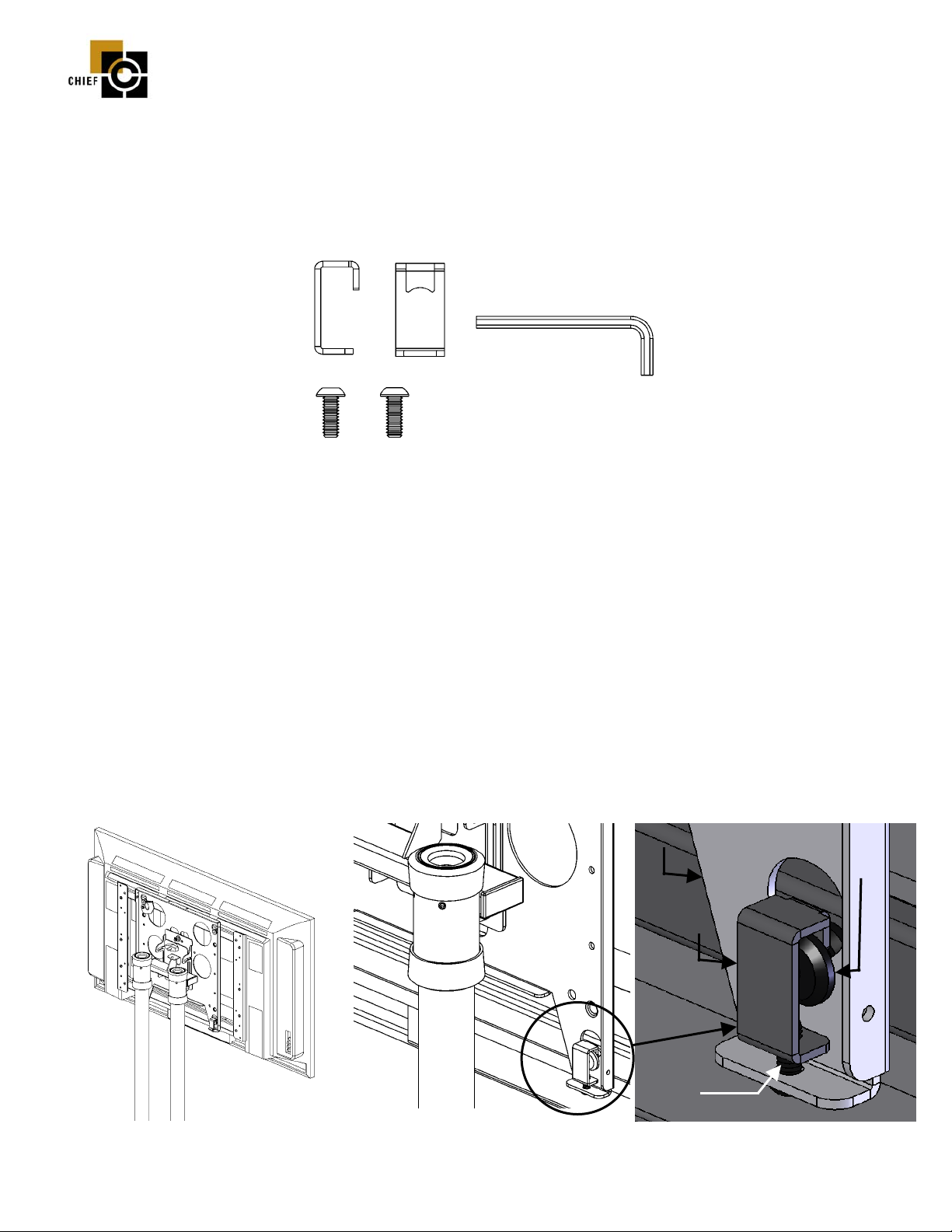
Prior to assembly, unpack carton completely and verify contents shown in Figure 1.
If you are missing any of the following components, please contact Customer Service at 1-800/582-6480.
Figure 1
(2) Q-Clamp
(2) ¼-20 x 7/8” Button Head Cap Screw
(1) 5/32” Allen Key
BEFORE PROCEEDING: Read installation instructions completely.
CAUTION! PLASMA DISPLAYS ARE EXTREMELY FRAGILE.
1. With the aid of another person, lift display up to the Chief mount, aligning the mounting buttons on the display with the
teardrop slots in the face plate. See Figure 2. (NOTE: PTC cart shown. Other mounts are similar.)
2. Place Q-Clamp over mounting button. Insert a ¼-20 button head cap screw into the bottom of the mount face plate.
Thread the cap screw into the bottom of the Q-Clamp. Tighten the cap screw until the Q-Clamp is snug on the mounting
button. See Figure 3 and Figure 4.
3. Repeat Step 2 to install the second Q-Clamp.
4. Raise the latching flag on the face plate, securing the display. Make sure latching flag is completely engaged.
Face plate
Mounting
Button
-Clamp
Thread
Cap Screw
into
Figure 2
8800-000028, Rev. B 06/27/05
CHIEF MANUFACTURING INC. 1-800-582-6480, Fax: 1-877-894-6918, Email: chief@chiefmfg.com
Figure 3
Q-Clamp
Figure 4
 Loading...