

CHIEF OFB-139 Installation Instructions Manual
INSTALLATION INSTRUCTIONS
g
t
OFB-139
TILE ASSEMBLY ADAPTER BRACKET
Prior to assembly, unpack carton completely and verify contents.
If you are missing any of the following components, please contact Customer Service at 1-800/582-6480
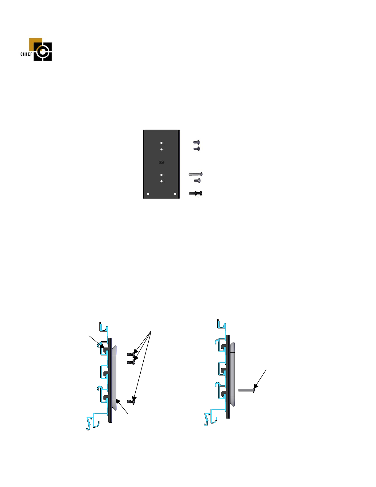
Figure 1
(1) Adapter Bracket (3) Screw, Pan Head, 10-24, Short
(1) Screw, Pan Head, 10-24, Long (2) Screw, Pan Head, 10-24, Black
BEFORE PROCEEDING, READ INSTALLATION INSTRUCTIONS COMPLETELY
NOTE: Suggested tool includes a magnetic screwdriver.
1. Secure the adapter bracket; with the tabs facing down, to the mounting bracket (supplied with your mounting
assembly) by installing three short 10-24 pan head screws (see Figure 2).
2. Install the adapter bracket in slots of the office furniture, tabs facing down, at desired location and push down
until seated.
3. Secure adapter bracket in place by installing the long 10-24 pan head screw (see Figure 3). Screw must fit into
office furniture slot. If screws do not fit into slot, the adapter bracket is not properly seated.
Adapter Bracket
Mountin
Short 10-24
Pan Head Screws (3)
Bracke
Long 10-24
Pan Head Screw
Figure 2
8812-000011 11/17/03
CHIEF MANUFACTURING INC. 1-800-582-6480, Fax: 1-877-894-6918, Email: chief@chiefmfg.com
Figure 3
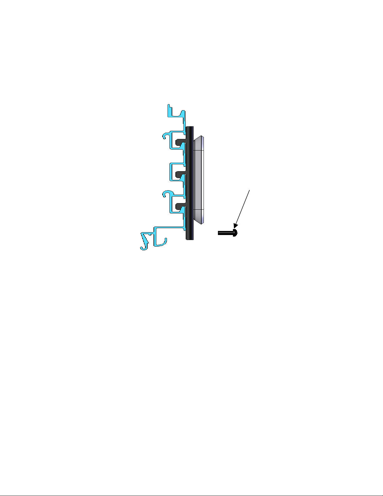
4. Install two 10-24 black pan head screws at bottom of adapter bracket (see Figure 4).
5. Install your mount as described in the directions accompanying your mount.
Figure 4
10-24 Black Pan Head Screws (2)
8812-000011 11/17/03
CHIEF MANUFACTURING INC. 1-800-582-6480, Fax: 1-877-894-6918, Email: chief@chiefmfg.com
 Loading...