

CHIEF MTA, MSA User Manual [ru]
INSTALLATION INSTRUCTIONS
ИНСТРУКЦИИ ПО УСТАНОВКЕ
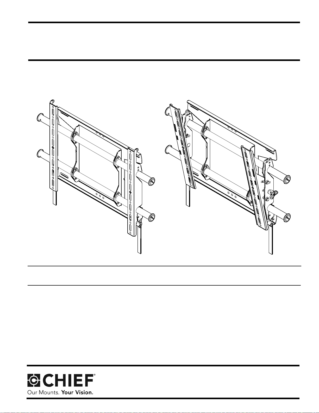
MSA
MTA
FUSION MEDIUM FLAT PANEL MOUNTS
• Go to http://downloads.chiefmfg.com/MANUALS-I/MSA_MTASeries-I.pdf for translated instructions.
• Переведенные инструкции находятся по адресу
• http://downloads.chiefmfg.com/MANUALS-I/MSA_MTASeries-I.pdf
German Product Description
Portuguese Product Description
Italian Product Description
MSA/MTA Series
MSA/MTA Series Installation Instructions
DISCLAIMER
Milestone AV Technologies, and its affiliated corporations and
subsidiaries (collectively “Milestone”), intend to make this
manual accurate and complete. However, Milestone makes no
claim that the information contained herein covers all details,
conditions or variations, nor does it provide for every possible
contingency in connection with the installation or use of this
product. The information contained in this document is subject
to change without notice or obligation of any kind. Milestone
makes no representation of warranty, expressed or implied,
regarding the information contained herein. Milestone assumes
no responsibility for accuracy, completeness or sufficiency of
the information contained in this document.
Chief® is a registered trademark of Milestone AV Technologies.
All rights reserved.
WARNING: Never operate this mounting system if it is
damaged. Return the mounting system to a service center for
examination and repair.
WARNING: Do not use this product outdoors.
IMPORTANT ! : The MSA/MTA mounts are designed to be
mounted to an 8" bare concrete wall, 8"x8"x16" bare concrete
block wall, or a 2" x 4" wood studs (16" on center) wall covered
by drywall with a maximum thickness of 5/8".
--SAVE THESE INSTRUCTIONS--
IMPORTANT SAFETY INSTRUCTIONS!
WARNING: A WARNING alerts you to the possibility of
serious injury or death if you do not follow the instructions.
CAUTION: A CAUTION alerts you to the possibility of
damage or destruction of equipment if you do not follow the
corresponding instructions.
WARNING: Failure to read, thoroughly understand, and
follow all instructions can result in serious personal injury,
damage to equipment, or voiding of factory warranty! It is the
installer’s responsibility to make sure all components are
properly assembled and installed using the instructions
provided.
WARNING: Failure to provide adequate structural strength
for this component can result in serious personal injury or
damage to equipment! It is the installer’s responsibility to
make sure the structure to which this component is attached
can support five times the combined weight of all equipment.
Reinforce the structure as required before installing the
component.
WARNING: Exceeding the weight capacity can result in
serious personal injury or damage to equipment! It is the
installer’s responsibility to make sure the combined weight of
all components located between the MSA/MTA up to (and
including) the display does not exceed 125 lbs (56.7 kg) for
dual stud attachment and concrete, and 75 lbs (34.0 kg) for
single stud attachment.
WARNING: Use this mounting system only for its intended
use as described in these instructions. Do not use
attachments not recommended by the manufacturer.
2
Installation Instructions MSA/MTA Series
12.00 304.8
9.58 243.4
.75 19.1
1.50 38.1
25.57 649.5
18.75 476.2
1.50 38.1
.34 8.6
11.00 279.4
16.00 406.4
8.00 203.2
13.50 342.9
4.83 122.6
12°
1.40 35.5
1.06 27
.32
8.1
.38
9.5
16.50
419.1
0
.45 11.5
1.97 50
2.42 61.5
3.94 100
4.39
111.5
5.91 150
6.36
161.5
7.87 200
.45 11.5
1.97 50
2.42 61.5
3.94
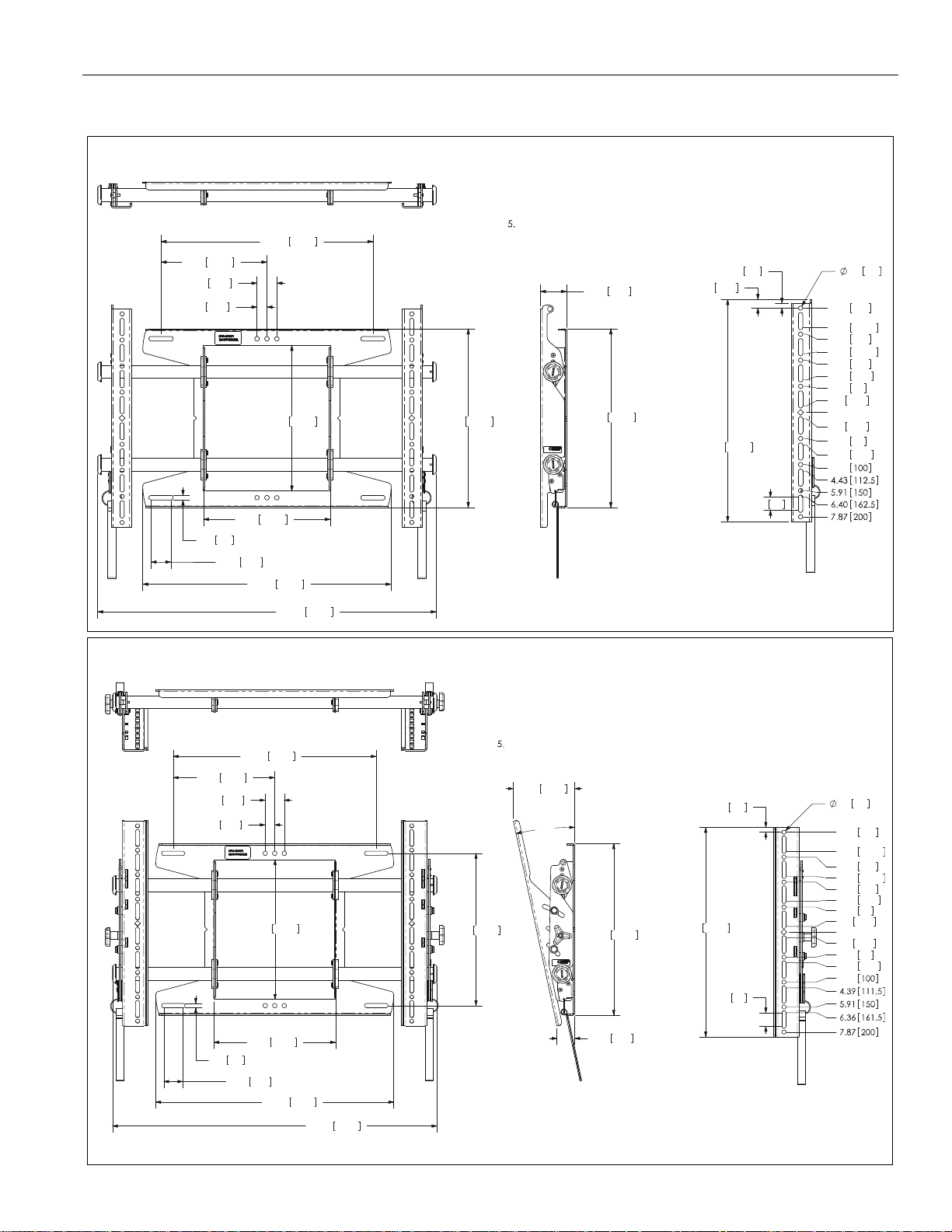
NOTES:
MAX MOUNTING PATTERN IS 22"[55 8.8mm] WITHOUT REVERSING UPRIGHTS .
1.
MAX MOUNTING PATTERN IS 26.5"[673.1mm] WIT H RE VERSING UPRIGHTS.2.
FOR RECESSED APPLICATIONS, MINIMUM VERTICAL LIFT FOR HOOK 3.
ENGAGEMENT IS .56"[14.2mm].
MOUNT RAILS CAN BE SLID LEFT OR RIGHT FOR OFFSET APPLICATIONS.4.
MOUNT IS 1.99"[50.5mm] DEEP WHEN FLAT TO WALL.
MTA
DIMENSIONS: [MILLIMETERS]
INCHES
25.57 649.5
18.75 476.2
.75 19.1
1.50 38.1
1.50 38.1
.34 8.6
9.58 243.4
11.00 279.4 13.50 342.9
16.00 406.4
8.00 203.2
1.96 49.8
13.50 342.9
16.78 426.1
.32
8.1
.38
9.6
.65
16.5
.98 25
0
.49
12.5
1.97 50
2.46
62.5
3.94 100
4.43
112.5
5.91 150
6.40
162.5
7.87 200
.49 12.5
1.97 50
2.46 62.5
3.94
NOTES:
MAX MOUNTING PATTERN IS 22.9"[581.6mm] WITHOUT REVERSING UPRIGHTS.
1.
MAX MOUNTING PATTERN IS 25.5"[647.7mm] WITH REVERSING UPRIGHTS.2.
FOR RECESSED APPLICATIONS, MINIMUM VERTICAL LIFT FOR HOOK 3.
ENGAGEMENT IS .56"[14.2mm].
MOUNT RAILS CAN BE SLID LEFT OR RIGHT FOR OFFSET APPLICATIONS.4.
MOUNT IS 1.96"[49.8mm] DEEP WHEN FLAT TO WALL.
DIMENSIONS: [MILLIMETERS]
INCHES
MSA
DIMENSIONS
3
Installation Instructions MSA/MTA Series
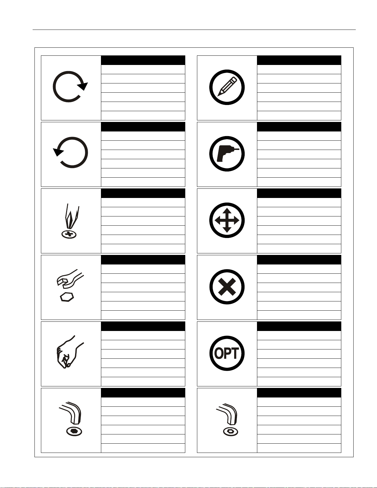
Tighten Fastener
Apretar elemento de fijación
Befestigungsteil festziehen
Apertar fixador
Serrare il fissaggio
Bevestiging vastdraaien
Serrez les fixations
Loosen Fastener
Aflojar elemento de fijación
Befestigungsteil lösen
Desapertar fixador
Allentare il fissaggio
Bevestiging losdraaien
Desserrez les fixations
Phillips Screwdriver
Destornillador Phillips
Kreuzschlitzschraubendreher
Chave de fendas Phillips
Cacciavite a stella
Kruiskopschroevendraaier
Tournevis à pointe cruciforme
Open-Ended Wrench
Llave de boca
Gabelschlüssel
Chave de bocas
Chiave a punte aperte
Steeksleutel
Clé à fourche
By Hand
A mano
Von Hand
Com a mão
A mano
Met de hand
À la main
Hex-Head Wrench
Llave de cabeza hexagonal
Sechskantschlüssel
Chave de cabeça sextavada
Chiave esagonale
Zeskantsleutel
Clé à tête hexagonale
Pencil Mark
Marcar con lápiz
Stiftmarkierung
Marcar com lápis
Segno a matita
Potloodmerkteken
Marquage au crayon
Drill Hole
Perforar
Bohrloch
Fazer furo
Praticare un foro
Gat boren
Percez un trou
Adjust
Ajustar
Einstellen
Ajustar
Regolare
Afstellen
Ajuster
Remove
Quitar
Entfernen
Remover
Rimuovere
Verwijderen
Retirez
Optional
Opcional
Optional
Opcional
Opzionale
Optie
En option
Security Wrench
Llave de seguridad
Sicherheitsschlüssel
Chave de segurança
Chiave di sicurezza
Veiligheidssleutel
Clé de sécurité
LEGEND
4
MSA/MTA Series Installation Instructions
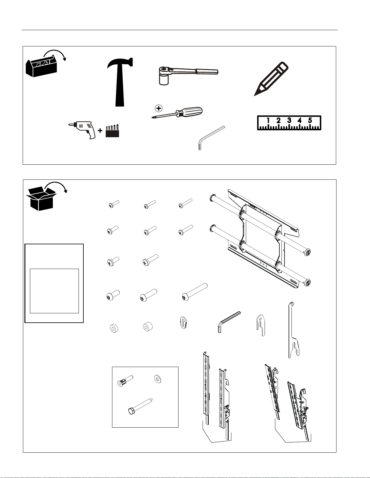
#2
7/32” (5.5mm) Wood Stud
5/16” (7.9mm) Concrete
M5
(included)
Custom
MSA6XXX/
MTA6XXX
Hardware
[Included with
MSA6XXX/MTA6XXX
Models Only]
C (6)
E (6)
(MSA Only)
(MTA Only)
T (1)
S (1)
(MSA Only)
(MTA Only)
A (8)
M4x16mm
B (6)
M4x20mm
M4x25mm
D (6)
M5x16mm
M5x20mm
F (6)
M5x25mm
G (6)
M6x16mm
H (6)
M6x25mm
P (1)
M5
I (6)
M8x20mm
J (6)
M8x30mm
K (4)
M8x50mm
L (8)
.750x.323x.250
M (8)
.750x.344x.500
N (8)
QA (4)
5/16”
QB (4)
5/16”
QC (4)
5/16” x 2-1/2”
[A-N used on MSAU/MTAU Models Only]
R (1)
U (1)
V (1)
W (1)
X (1)
[Wall bracket]
TOOLS REQUIRED FOR INSTALLATION
PARTS
5
MSA/MTA Series Installation Instructions
Center of screen
6"
Vertical center
of mount
5
5
Single Stud
Installation
Dual Stud
Installation
INSTALLATION
The MSA/MTA mounts are designed to be mounted to an 8"
bare concrete wall, 8"x8"x16" bare concrete block wall, or a 2" x
4" wood studs (16" on center) wall covered by drywall with a
maximum thickness of 5/8". The MTA has brackets which allow
the TV to be tilted. The MSA has static brackets which keep the
TV in an upright position.
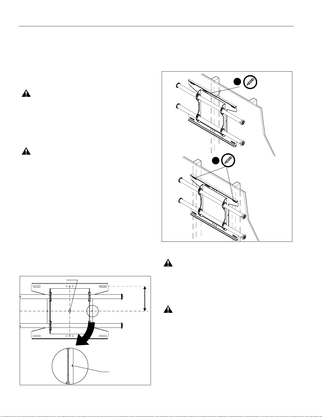
Locate Mounting Site
WARNING: IMPROPER INSTALLATION CAN LEAD TO
MOUNT FALLING CAUSING SEVERE PERSONAL INJURY
OR DAMAGE TO EQUIPMENT! It is the installers
responsibility to make certain the structure to which the
mount is being attached is capable of supporting five times
the weight of the MSA/MTA not to exceed 125 lbs (56.7 kg)
for dual stud attachment, and 75 lbs (34.0 kg) for single stud
attachment.
WARNING: Proceed to either the Installing to a Wood
Stud Wall section or the Installing to a Concrete Wall
section.
Installing to a Wood Stud Wall
5. Using a level, mark the wall on each stud to attach the wall
bracket (R) through the upper mounting slots. (See Figure 2)
NOTE: The MSA and MTA may be attached through the
mounting slots on dual studs, or through the center
mounting holes on a single stud. (See Figure 2)
1. Determine the center of the TV screen, and where it should
be located on the wall.
2. Locate the closest stud to the left and right of the selected
location.
NOTE: If the screen area lies over a stud, use that stud if using
the single stud installation method.
NOTE: Use that stud and the stud to either the left or right of it
if using the dual stud installation method.
3. Line up the notches on mount with center of screen marking
to determine vertical center. (See Figure 1)
4. Measure up 6" (152.4mm) from the center point to mark
location of the upper mounting slots.
Figure 2
WARNING: ELECTRICAL SHOCK HAZARD! CUTTING
OR DRILLING INTO ELECTRICAL CORDS OR CABLES
CAN CAUSE DEATH OR SERIOUS PERSONAL INJURY!
ALWAYS make certain area behind mounting surface is free
of electrical wires and cables before drilling or installing
fasteners.
WARNING: EXPLOSION AND FIRE HAZARD! CUTTING
OR DRILLING INTO GAS PLUMBING CAN CAUSE DEATH
OR SERIOUS PERSONAL INJURY! ALWAYS make certain
area behind mounting surface is free of gas, water, waste, or
any other plumbing before cutting, drilling, or installing
fasteners.
Figure 1
6
 Loading...