

Page 1
Page 2
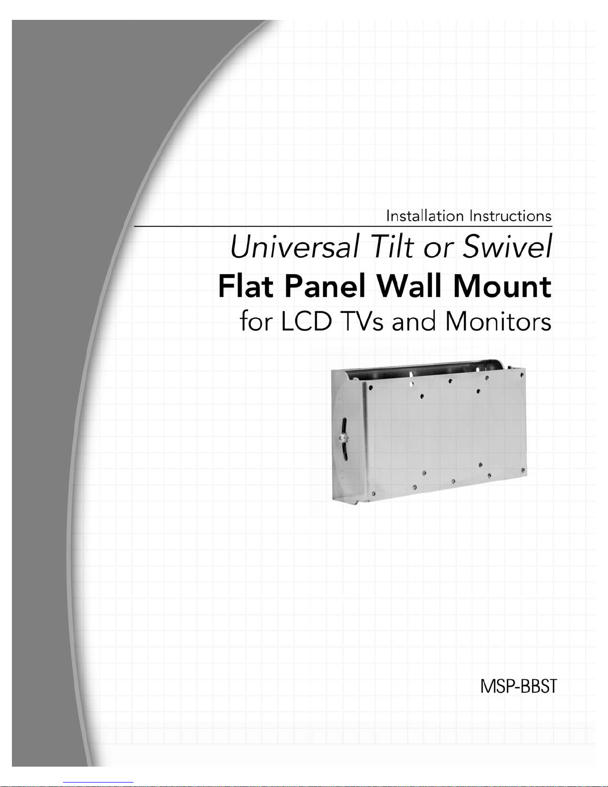
Installation Instructions MSP-BBST
IMPORTANT WARNINGS and CAUTIONS!
WARNING
A WARNING alerts you to the possibility of serious injury or death if you do not follow
the instructions.
CAUTION A CAUTION alerts you to the possibility of damage or destruction of equipment if you do not
follow the corresponding instructions.
WARNING
Improper installation can result in serious personal injury! Make sure that the
mounting surface can support a redundant weight factor five times the total weight of
the equipment. If not, reinforce the mounting surface structural members before
installing the mount.
WARNING
Be aware of the potential for personal injury or damage to the unit if it is not
adequately mounted.
WARNING
The installer is responsible for verifying that the mounting surface to which the
mount is anchored will safely support the combined load of all attached components
or other equipment.
WARNING
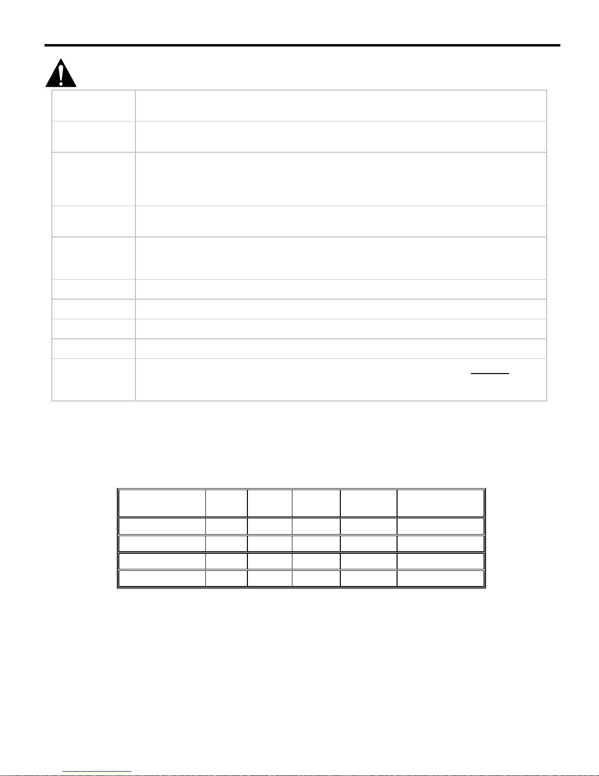
Weight Specifications (see Table 1).
WARNING Watch for pinch points. Do not put your fingers between movable parts.
WARNING Make sure the mount is correctly oriented.
CAUTION
Check the unit for shipping damage before you begin the installation.
CAUTION If your monitor uses a longer screw size other than those included in the kit, DO NOT use
the screws provided with the mount. Use the screws provided with your monitor or contact
the manufacturer. Using the wrong screws could result in damage to your monitor.
WEIGHT SPECIFICATIONS
Table 1 contains the weight specifications for the various tilt mount VESA configurations.
Table 1. Weight Specifications
VESA HOLE
PATTERN
75MM X 75MM
100MM X 100MM
200MM X 100MM
200MM X 200MM
4-HOLE 6-HOLE
X X X 45
X X X 45
X X X 45
X X 45
FLUSH
MOUNT
RECESSED
MOUNT
MAX SUPPORT
LBS. (20.4KG)
LBS. (20.4KG)
LBS. (20.4KG)
LBS. (20.4KG)
WEIGHT
2
Page 3

Installation Instructions MSP-BBST
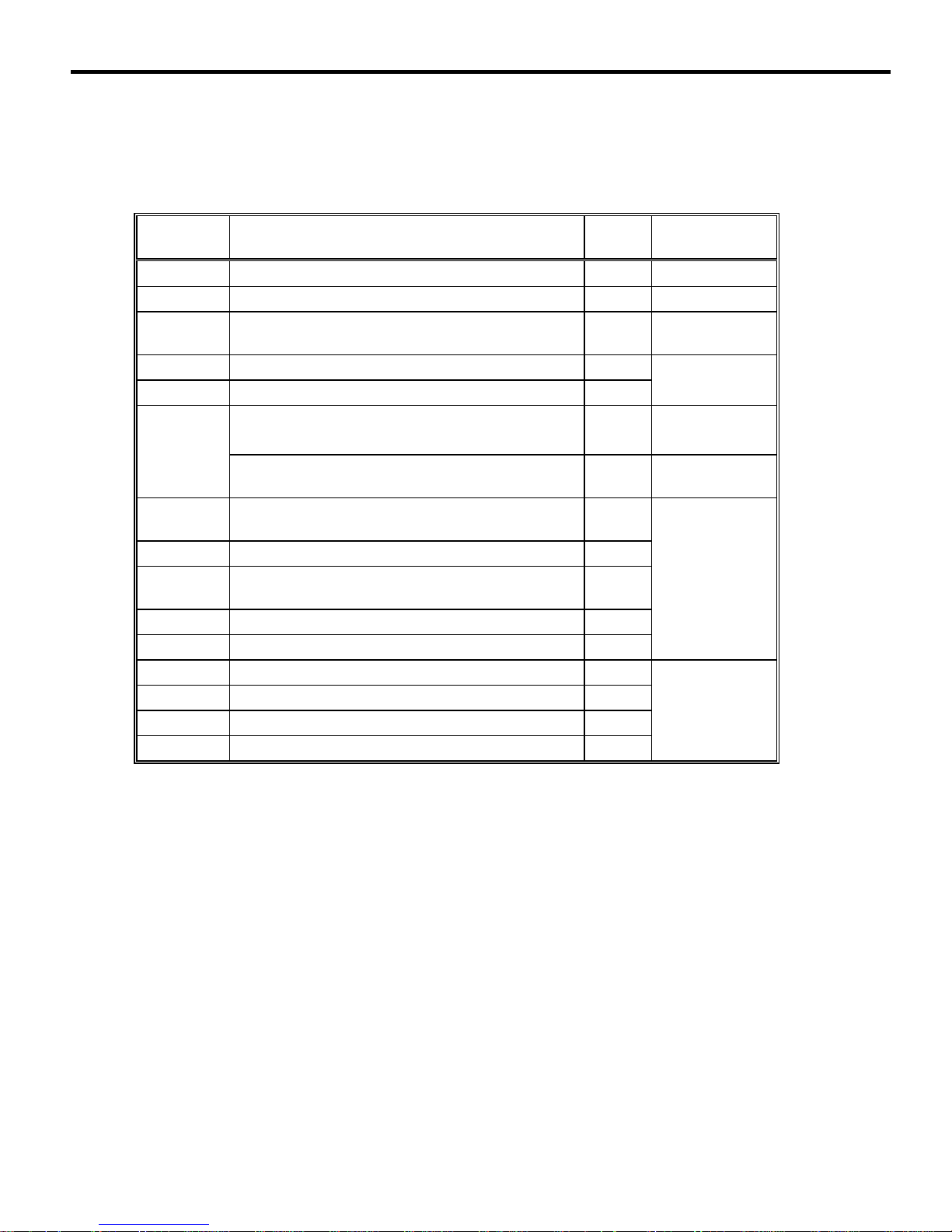
TOOLS REQUIRED FOR
CONTENTS
WEIGHT SPECIFICATIONS..........................................2
TOOLS REQUIRED FOR INSTALLATION....................3
TILT MOUNT KIT ...........................................................4
Tilt Mount Without Bracket Adapters..........................5
Tilt Mount With Bracket Adapters...............................5
INSTALLATION..............................................................6
Wall Stud Installation (Step 1) ....................................6
Attaching the VESA Bracket to the Display (Step 2) ..6
Flush Mount (Without Bracket Adapter)..................7
Recessed Mount .....................................................8
Flush Mount (With Bracket Adapter).......................9
Mounting the Display on the Wall Bracket (Step 3)....10
Locking the Display on the Wall Bracket (Step 4) ......10
INSTALLATION
• Phillips screwdriver
• Drill and drill bits
NOTE: Other tools may be required depending on your
method of installation.
3
Page 4
Installation Instructions MSP-BBST
TILT MOUNT KIT
Unpack the carton. Verify the kit contents shown in Table 2. Read installation instructions completely. If you are
missing any of the listed components, please contact Customer Service at 1-800/582-6480.
Table 2. Tilt Mount Kit
ITEM
NUMBER DESCRIPTION QTY NOTES
10 BRKT, VESA TILT INTERFACE 1
20 BRKT, WALL TILT MOUNT 1
30 PHILLIPS HEAD WOOD SCREW, 2-1/2” 2
40 NYLON WASHER 2
50 PHILLIPS PAN HEAD MACHINE SCREW, M5 X 10MM 2
60
70
PHILLIPS PAN HEAD MACHINE SCREW, M4 X 12MM
OR
PHILLIPS PAN HEAD MACHINE SCREW, M4 X 12MM 4
PHILLIPS PAN HEAD MACHINE SCREW, M4 X 20MM
6
6
(USE WITH 80 OR 110) *
80 3/8” NYLON SPACER 6
90
PHILLIPS PAN HEAD MACHINE SCREW, M4 X 30MM
6
(USE WITH 100) **
100 3/4” NYLON SPACER 6
110 1/8” NYLON SPACER (USE WITH 90) *** 6
120 BRACKET ADAPTER 2
130 WASHER, M4 4
140 PHILLIPS PAN HEAD MACHINE SCREW, M6 X 10MM 4
150 PHILLIPS PAN HEAD MACHINE SCREW, M4 X 5MM 4
SINGLE STUD
MOUNTED
TILT
ADJUSTMENT
FLUSH MOUNT
200
MM X 200MM
MOUNT
RECESSED
MOUNT
MM X 200MM
200
MOUNT
• *Use M4 x 20mm screws (70) with spacers (80) for recessed mount applications.
• **Use M4 x 30mm screws (90) with spacers (100) for recessed mount applications.
• ***Use M4 x 20mm screws (70) with spacers (110) for recessed mount applications.
4
Page 5

Installation Instructions MSP-BBST
Tilt Mount Without Bracket Adapters
75mm x 75mm
VESA CHART (WITHOUT BRACKET ADAPTERS)
100mm x 100mm
200mm x 100mm
Tilt Mount With Bracket Adapters
VESA HOLE
PATTERN
4-HOLE 6-HOLE
75MM X 75MM
100MM X 100MM
200MM X 100MM
VESA CHART (WITH BRACKET ADAPTERS)
FLUSH
MOUNT
RECESSED
MOUNT
X X X
X X X
X X X
200mm x 200mm
VESA HOLE
PATTERN
4-HOLE
200MM X 200MM
X X
FLUSH
MOUNT
5
Page 6

Installation Instructions MSP-BBST
INSTALLATION
The following procedures describe how to install the
tilt mount.
NOTE: Read “Warnings and Cautions” on Page 2.
20
Wall Stud Installation (Step 1)
Install the wall bracket on a wall stud, as follows:
1. Determine the exact mounting location prior to
installation, considering screen size as well as
the mount swing and extension radius.
2. Position the wall bracket (20) as desired.
NOTE: Mark the mounting holes as accurately as
possible before drilling the holes. The holes
must be centered for the wall bracket to fit
correctly on the wall.
3. Locate stud and, using wall bracket (20) as a
template at the desired height, mark the location
of the two center mounting holes.
4. Using the two wood screws (30), secure wall
bracket (20) to wall.
Mounting
Hole
Figure 1. Installing Wall Bracket — Wall Stud
Center
Mounting
Holes
Attaching the VESA Bracket to the
Display (Step 2)
Depending on the VESA hole-pattern on your
display, select the applicable set of instructions,
listed below, to attach the VESA bracket to your
display:
• Flush Mount (Without Bracket Adapter)
− 75mm/75mm compliant displays
− 100mm/100mm compliant displays
− 200mm/100mm compliant displays
• Recessed Mount (spacers are used)
− 75mm/75mm compliant displays
− 100mm/100mm compliant displays
− 200mm/100mm compliant displays
• Flush Mount (With Bracket Adapter)
− 200mm/200mm compliant displays
CAUTION:
If monitor uses a screw size other than those
included in the kit, DO NOT use the screws provided.
Using the wrong screws could result in damage to
your monitor.
6
Page 7

Installation Instructions MSP-BBST
Flush Mount (Without Bracket Adapter)
To attach the VESA bracket using the recessed
mount procedure, do the following:
1. Place the VESA bracket (10) on the display.
2. Align the hole-pattern of your display with the
hole-pattern on the VESA bracket (10).
3. Attach VESA bracket (10) to the display using six
M4 X 10mm screws (50) provided.
50
10
Figure 2. Flush Mount
200mm/100mm Display (shown)
7
Page 8

Installation Instructions MSP-BBST
Recessed Mount
To attach the VESA bracket using the recessed
mount procedure, do the following:
1. Refer to the applicable table (listed below) and
select six screws and six spacers.
• See to Table 3 for 75mm/100mm and
100mm/100mm compliant displays.
• See Table 4 for 200mm/100mm compliant
displays.
2. Select option 1, 2, or 3 to pick the applicable
screw and spacer combination.
3. Set six spacers over the four mounting holes on
your monitor (see Figure 3. Recessed Mount
200mm/100mm Display (shown)).
4. Set VESA interface bracket (10) on top of
spacers and install six screws into the mounting
holes of your display.
Table 3. 75mm/75mm and 100mm /100mm
Compliant Displays
6
Screws
NOTE:
For additional
information,
see VESA
Chart, page 5
10
6
Spacers
OPTION SCREW QTY SPACER QTY
1 70 4 80 4
2 90 4 100 4
3 70 4 110 4
Table 4. 200mm/100mm Compliant Displays
OPTION SCREW QTY SPACER QTY
1 70 6 80 6
2 90 6 100 6
3 70 6 110 6
Figure 3. Recessed Mount
200mm/100mm Display (shown)
8
Page 9

Installation Instructions MSP-BBST
Flush Mount (With Bracket Adapter)
To attach the VESA bracket using the recessed
mount procedure, do the following:
1. Select the two bracket adapters (120), four
washers (130), and four screws (refer to the
Table 5) that will be used to install the VESA
bracket for 200mm/200mm compliant displays.
2. Align the two bracket adapters (120) with the
200mm/200mm hole-pattern of your display.
3. To attach the two bracket adapters (120) to your
display, use one of the following options:
a. Four M6 X 10mm screws (140). Or,
b. Four M4 X 12mm screws (60) and four M4
washers (130).
4. Place the VESA bracket (10) on the two bracket
adapters (120).
Table 5. 200mm /200mm Compliant Displays
ITEM DESCRIPTION QTY NOTES
120 BRACKET ADAPTER 2 2
130 WASHER, M4 (USE WITH 60) 4 4
140 PHILLIPS SCREW, M6 X 10MM 4
60 PHILLIPS SCREW, M4 X 12MM 4
150 PHILLIPS SCREW, M4 X 5MM 4
BRACKET
ADAPTER
TO DISPLAY
VESA
BRACKET
TO
BRACKET
ADAPTER
5. Align the VESA bracket (10) with the hole-pattern
on the two bracket adapters (120).
6. Attach VESA bracket (10) to the two bracket
adapters (120) using four M4 X 5mm screws
(150).
7. Tighten (do not over-tighten) the screws.
10
130
Figure 4. Flush Mount — 200mm x 200mm Compliant Displays
9
Page 10

Installation Instructions MSP-BBST
Mounting the Display on the Wall
Bracket (Step 3)
To mount the display on the wall bracket, do the
following:
1. With an assistant (if necessary), lift the display up to
the wall bracket (20) over the four mounting pins.
2. Align the mounting pins on the display with the slots
in the wall bracket (20), and set the display into
place.
3. Verify that the display tilts on the wall bracket (20).
20
Figure 5. Assemble the Brackets
Locking the Display on the Wall
Bracket (Step 4)
To lock the display on the wall bracket, do the following:
1. Assemble a washer (40) over each M5 screw (50).
Install the two M5 (50) screw assemblies into the
tapped holes located on the side of the wall bracket
(20).
2. Set the display into the desired position. Tighten the
M5 screw (50) until friction holds the display
stationary.
Tapped
Hole
40
50
Figure 6. Install the M5 Screw
10
Page 11

Page 12

Chief Manufacturing Inc.
8401 Eagle Creek Parkway, Suite 700 CSAV Europe B.V.
Savage, MN 55378, USA Zekeringstraat 17, 1014 BM
PHONE: 800.582.6480 Amsterdam, Netherlands
PHONE: 952.277.3901 PHONE: 31 (0)20 5708923
FAX: 952.894.6918 FAX: 31 020 5708989
FAX: 877.894.6918 europe@chiefmfg.com
www.chiefmfg.com
©2005 Chief Manufacturing Inc. All rights reserved.
Patents and patents pending.
9/05
8832-000091 (Rev. B)
 Loading...