

Page 1
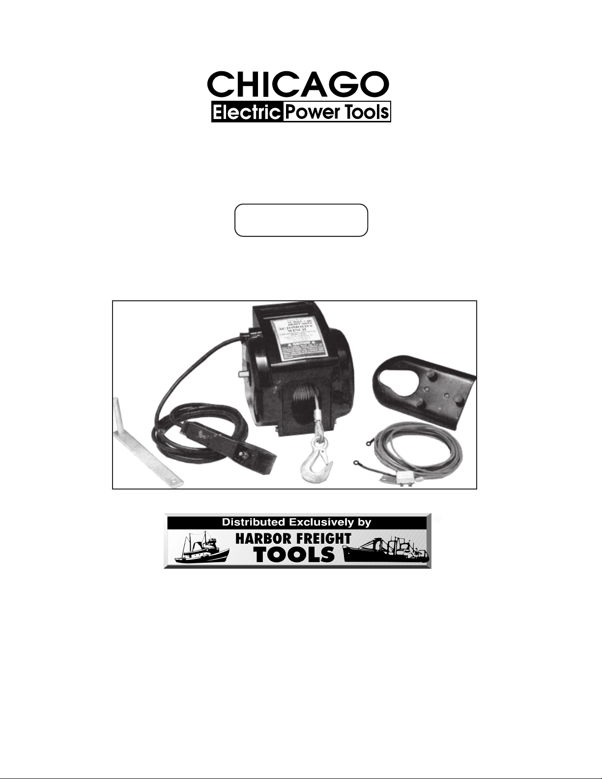
12 VOLT WINCH
®
(POWER IN / POWER OUT)
Model 03882
ASSEMBLY AND OPERATING INSTRUCTIONS
3491 Mission Oaks Blvd., Camarillo, CA 93011
Visit our Web site at http//www.harborfreight.com
Copyright© 2004 by Harbor Freight Tools®. All rights reserved. No portion of
this manual or any artwork contained herein may be reproduced in any shape
or form without the express written consent of Harbor Freight Tools.
For technical questions, please call 1-800-444-3353.
REVISED MANUAL 04/03; REV 01/05
Page 2

PRODUCT SPECIFICATIONS
Item Description
Electrical Requirements 12 Volt DC Input
Load Capacities 9,500 Lbs. (Rolling)
8,500 Lbs. (Marine)
3,000 Lbs. (Pulling)
Power In and Out Capability Yes
Line Speed 10 Ft. Per Minute with Load
Cable Length 36 Ft.
Battery Cable Lengths 10 Ft. for Negative Lead
25 Ft.-2 In. for Positive Lead
Remote Cable Length 10 Ft.
Mounting Plate Dimensions 8-3/4” L x 4-15/16” H x 3/16” W
Main Hook Size 5/8” Opening x 4-1/4” Long
Pulley Hook Size 5/8” Opening x 7-5/8” Long
Net Weight 40 Lbs.
SAVE THIS MANUAL
You will need this manual for the safety warnings and precautions, assembly,
operating, inspection, maintenance and cleaning procedures, parts list and assembly diagram. Keep your invoice with this manual. Write the invoice number
on the inside of the front cover. Keep this manual and invoice in a safe and dry
place for future reference.
GENERAL SAFETY WARNINGS AND PRECAUTIONS
1. KEEP WORK AREA CLEAN AND DRY. Cluttered, damp, or wet work areas
invite injuries.
2. KEEP CHILDREN AWAY FROM WORK AREA. Do not allow children to handle
this product.
3. STORE IDLE EQUIPMENT. When not in use, tools and equipment should be
stored in a dry location to inhibit rust. Always lock up tools and equipment, and
keep out of reach of children.
4. DO NOT USE THIS PRODUCT IF UNDER THE INFLUENCE OF ALCOHOL OR
DRUGS. Read warning labels on prescriptions to determine if your judgement or
reflexes are impaired while taking drugs. If there is any doubt, do not attempt to
use this product.
SKU 03882 For technical questions, please call 1-800-444-3353. PAGE 2
Page 3

5. USE EYE PROTECTION. Wear ANSI approved safety impact eye goggles when
assembling and using this product. ANSI approved safety impact eye goggles
are available from Harbor Freight Tools.
6. DRESS SAFELY. Do not wear loose clothing or jewelry, as they can become
caught in moving parts. Wear a protective hair covering to prevent long hair from
becoming caught in moving parts. If wearing a long-sleeve shirt, roll sleeves up
above elbows.
7. DO NOT OVERREACH. Keep proper footing and balance at all times to prevent
tripping, falling, back injury, etc.
8. INDUSTRIAL APPLICATIONS MUST FOLLOW OSHA REQUIREMENTS.
9. STAY ALERT. Watch what you are doing at all times. Use common sense. Do
not use this product when you are tired or distracted from the job at hand.
10. CHECK FOR DAMAGED PARTS. Before using this product, carefully check that
it will operate properly and perform its intended function. Check for damaged
parts and any other conditions that may affect the operation of this product.
Replace or repair damaged or worn parts immediately.
11. REPLACEMENT PARTS AND ACCESSORIES: When servicing, use only identi-
cal replacement parts. Only use accessories intended for use with this product.
Approved accessories are available from Harbor Freight Tools.
12. MAINTAIN THIS PRODUCT WITH CARE. Keep this product clean and dry for
better and safer performance.
13. MAINTENANCE: For your safety, service and maintenance should be performed
regularly by a qualified technician.
14. USE THE RIGHT TOOL FOR THE JOB. Do not attempt to force a small tool or
attachment to do the work of a larger industrial tool. There are certain applications for which this tool was designed. It will do the job better and more safely at
the rate for which it was intended. Do not modify this tool, and do not use this
tool for a purpose for which it was not intended.
15. WARNING: The warnings, precautions, and instructions discussed in this
manual cannot cover all possible conditions and situations that may occur. The
operator must understand that common sense and caution are factors, which
cannot be built into this product, but must be supplied by the operator.
SKU 03882 For technical questions, please call 1-800-444-3353. PAGE 3
Page 4

SPECIFIC PRODUCT WARNINGS AND PRECAUTIONS
1. DO NOT EXCEED THE MAXIMUM RATED LOAD CAPACITY FOR THE
WINCH; (9,500 LBS. ROLLING), (8,500 LBS. MARINE), (3,000 LBS. PULLING). Never use the Hand Crank (1) to “assist” the Winch. Overloading the Winch
could cause serious personal injury and/or property damage.
2. THE WINCH IS DESIGNED FOR INTERMITTENT USE ONLY. Do not use the
Winch in a constant duty application. The duration of the pulling job should be
kept as short as possible. If the Winch becomes very hot to the touch, stop the
Winch and let it cool down for several minutes. Never pull for more than one
minute at or near the rated load capacities. Do not maintain power to the Winch
if the Motor (65) stalls.
3. MAKE SURE TO READ AND UNDERSTAND ALL INSTRUCTIONS AND
SAFETY PRECAUTIONS AS OUTLINED IN THE MANUFACTURER’S
MANUAL FOR THE VEHICLE/TRAILER TO WHICH THE WINCH WILL BE
ATTACHED.
4. MAKE SURE TO READ AND UNDERSTAND ALL INSTRUCTIONS AND
SAFETY PRECAUTIONS AS OUTLINED IN THE MANUFACTURER’S
MANUAL FOR THE OBJECT YOU WILL WINCH. Make sure to attach the Winch
Cable Hook (57) of the Winch to the manufacturer’s recommended pulling point.
5. ALWAYS EXAMINE THE WINCH FOR STRUCTURAL CRACKS, BENDS,
DAMAGE, FRAYED CABLE, AND ANY OTHER CONDITIONS THAT MAY
AFFECT THE SAFE OPERATION OF THE WINCH. Do not use the Winch even
if minor damage appears.
6. MAINTAIN A SAFE WORKING ENVIRONMENT. Keep the work area well lit.
Make sure there is adequate surrounding workspace. Always keep the work
area free of obstructions, grease, oil, trash, and other debris.
7. ALWAYS KEEP HANDS AND FINGERS AWAY FROM THE GEARS OF THE
WINCH WHEN APPLYING OR RELEASING A LOAD. Remain clear of the
Winch Cable Hook (57) when pulling a load. Do not stand in line with the Cable
Assembly, as it could whip violently should it break. People and animals should
be kept at a safe distance when using the Winch.
8. USE EXTREME CAUTION WHEN APPLYING OR RELEASING A LOAD.
Never allow the load to suddenly release. Slowly and carefully apply and release
the load.
SKU 03882 For technical questions, please call 1-800-444-3353. PAGE 4
Page 5

9. NEVER WINCH A BOAT OR OTHER OBJECT WITH ANYONE IN OR ON IT.
Use a spotter to assist you in assuring that it is safe to operate the Winch. Make
sure this person is out of the way of the vehicle and the Steel Cable before activating the Winch.
10. WHEN MOUNTING THE WINCH ON A VEHICLE/TRAILER, MAKE SURE TO
ALLOW SUFFICIENT SPACE FOR THE WINCH’S HAND CRANK (1) TO BE
TURNED A FULL 360 DEGREES.
11. THE WINCH IS DESIGNED FOR MOUNTING ON SQUARE OR RECTANGULAR SURFACES ONLY. Do not attempt to mount the Winch on a rounded
surface.
12. THE WINCH IS NOT DESIGNED TO ACCOMMODATE ROPES OR FIBER-
GLASS STRAPS. Do not replace the Steel Cable with a Cable of lesser
strength.
13. THE STEEL CABLE MUST BE PULLED STRAIGHT IN. Keep the load in line
with the Winch. Pulling at an angle (off to the side) may cause excessive stress
on the Winch.
14. ALWAYS LEAVE AT LEAST FOUR TURNS OF STEEL CABLE ON THE
CABLE ASSEMBLY SHAFT TO PREVENT PULLING THE STEEL CABLE
COMPLETELY OUT OF THE WINCH.
15. DO NOT LEAVE THE WINCH UNATTENDED WHILE IT IS UNDER A LOAD.
16. WARNING: People with pacemakers should consult their physician(s) before
using this product. Operation of electrical equipment in close proximity to a heart
pacemaker could cause interference or failure of the pacemaker.
17. NEVER LIFT PEOPLE AND ANIMALS OR HOIST LOADS OVER PEOPLE.
UNPACKING
When unpacking, check to make sure all the parts shown on the Parts List (page 15)
are included. If any parts are missing or broken, please call Harbor Freight Tools at the
number shown on the cover of this manual as soon as possible.
REV 11/06
SKU 03882 For technical questions, please call 1-800-444-3353. PAGE 5
Page 6

ASSEMBLY INSTRUCTIONS
NOTE: For additional references to the parts listed below, refer to the Assembly
Diagram (page 16).
Permanent Mounting Of The Winch:
1. Select a mounting site on the bed of a truck, trailer, or other suitable location.
CAUTION: This Winch can generate 9,500 pounds rolling, 8,500 pounds
marine, and 3,000 pounds pulling force. Make sure the location selected
can withstand this much force. It may be required to use steel reinforcement plates (not included), and/or to weld on additional bracing (not included), depending on the desired mounting location.
2. Align the Base of the Winch with the desired location, and mark for drilling the
three
mounting holes required to attach the Winch to the desired location. Then,
drill these three mounting holes on the vehicle/trailer. (See Figure A.)
3. Use three hardened Steel Bolts at least 3/8” in diameter, three Lock Washers,
and three Nuts (all not included), to securely attach the Winch to the desired
location. (See Figure A.)
BOTTOM VIEW
MOUNTING HOLE (3/8”)
FIGURE A
BASE OF WINCH
MOUNTING HOLE (3/8”)
MOUNTING HOLE (3/8”)
3/8” BOLT
(NOT INCLUDED)
LOCK WASHER
(NOT INCLUDED)
SIDE VIEW
NUT
(NOT INCLUDED)
MOUNTING
SURFACE
SKU 03882 For technical questions, please call 1-800-444-3353. PAGE 6
Page 7

Temporary Mounting Of The Winch:
1. Insert three Screws (74) into the three mounting holes in the Adapter Plate, and
secure the Screws to the Adapter Plate, using three Washers (76), and three Nuts
(77). (See Figure B.)
2. Insert the heads of the three Screws (74) into the three keyhole slots on the Base
of the Winch. (See Figure B.)
3. Attach the Winch with its Plate (75) to the vehicle’s Hitch Ball (not included) by
inserting the Hitch Ball through the teardrop-shaped hole in the Adapter Plate.
(See Figure B.)
SIDE VIEW BOTTOM VIEW
(75)
PLATE
(75)
SCREW (74)
WASHER (76)
NUT (77)
HITCH BALL
(NOT INCLUDED)
PLATE (75)
FIGURE B
SKU 03882 For technical questions, please call 1-800-444-3353. PAGE 7
Page 8

To Connect The Electrical Wiring:
NOTICE: The use of an “Overload Protection Device” (circuit breaker) is highly recom-
mended in order to protect the vehicle and its battery from damage in case of a winch
failure/overload. A 50-amp circuit breaker (not included) should be purchased and installed in a safe location as close to the vehicle’s battery as possible. The circuit breaker
will be installed inline with the winch’s “20’ Lead Wire” (47) RED wire and the vehicle
battery. Two (2) solderless, insulated, 12-10 AWG ring tongue terminals (not included) will
also be needed to install the circuit breaker. The rings on the terminals will need to be big
enough to fit on the battery terminal bolt.
1.
NOTE: Depending on your level of knowledge regarding electrical wiring, you
may wish to have this procedure performed by a qualified technician.
2. CAUTION: Prior to performing this procedure, make sure the vehicle engine is
turned off. Make sure the vehicle transmission is in its “Park” position and
emergency brake is on. Also, make sure the engine, transmission, and exhaust system is cool to the touch.
3.
To connect the wiring
, plan a route for the Wire Harness Assembly (64) from the
point of where the Winch will be mounted on the vehicle to the vehicle’s 12 Volt DC
Battery. The route should be secure, out of the way of moving parts, road debris, or
any possibility of being damaged by operation or maintenance of the vehicle. For
example, the Power Cord may be routed under the vehicle, attaching it to the frame
using suitable fasteners (not included). Do not attach the Power Cord to the exhaust system, drive shaft, emergency brake cable, fuel line, or any other components which may create damage to the Power Cord through heat or motion, or create a fire hazard. If a hole is drilled through the bumper or any other part of the
vehicle, make sure to install a rubber grommet (not included) in the hole to prevent
fraying of the wires at that point.
4. Route the Wire Harness Assembly (64), following the precautions discussed in Step
3. Once the Wire Harness Assembly (64) is routed to the Battery, attach the RED,
color coded, Ring Electrical Connector to the POSITIVE (+) terminal of the Battery.
(See Figure C.)
5. Attach the BLACK, color coded, Ring Electrical Connector to the NEGATIVE (–)
terminal of the Battery. (See Figure C.)
6. WARNING: Never continue using the Winch until the vehicle’s 12 Volt DC Battery is
run down. You may wish to keep the engine running while using the Winch to continually recharge the Battery. However, make sure the vehicle is in “neutral”, the
vehicle’s emergency brake has been set and, whenever possible, the vehicle’s
wheels have been chocked. Do not use a dirty, corroded, or leaking Battery to avoid
injury from possible acid burns. Always wear ANSI approved safety eye goggles
when working with or around a Battery.
7. WARNING: Carbon Monoxide is a colorless, odorless, gas emitted from the
engine’s exhaust that may KILL or cause serious personal INJURY when inhaled. Do not run the engine in an area without proper ventilation.
REV 08/03
SKU 03882 For technical questions, please call 1-800-444-3353. PAGE 8
Page 9

WIRE
HARNESS
ASSEMBLY
(64)
POWER
CORD
BLACK
RING
CONNECTOR
RED
RING
CONNECTOR
REMOTE
CONTROL
SOCKET
FIGURE C
To Connect The Remote Control:
Lift the Rubber Seal on the left side of the Winch, and insert the Cord Plug (8) into
the Remote Control Socket. Then, set the Remote Control Housing in a safe
place until ready for use. (See Figure D.)
REMOTE
CONTROL
SOCKET
CORD
PLUG
(8)
NEGATIVE
VEHICLE
BATTERY
(NOT INCLUDED)
POSITIVE
REMOTE
CONTROL
CORD
REMOTE CONTROL HOUSING
FIGURE D
REV 01/05
SKU 03882 For technical questions, please call 1-800-444-3353. PAGE 9
Page 10

To Attach The Hand Crank:
The Handle (1) has a hex opening that fits the jam nuts. A second adjustable
wrench will be needed to tighten the nuts (13) against each other. Then use
handle over one of the nuts for manual operation. For power operation in
either direction, the nuts must be tightened against the clutch. For manual
operation, back the nuts off then tighten them together.
the
HAND
CRANK
(1)
SHAFT (21)
CRANK
NUT (13)
STEEL CABLE
FIGURE E
OPERATING INSTRUCTIONS
To Use The Winch Manually:
1. WARNING: Do not use the Hand Crank (1) to assist a
damage the Winch, and may cause personal injury. (See Figure E.)
2. Place the vehicle’s transmission in “Park.” Turn off the engine. Set the emergency
brake, and block the wheels from rolling, using suitable chocks (not included).
3. To retract the cable:
a. Tighten both the Crank Nuts (13) on the end of the Shaft (21). The Hand Crank
will need to be removed temporarily to access the inner Crank Nut. Do not overtighten. (See Figure E.)
b. Rotate the Hand Crank (1) clockwise to tighten the Steel Cable. Continue turn-
ing the Hand Crank clockwise until the Steel Cable has been completely retracted. (See Figure E.)
4. To let cable out:
a. The clutch needs to be released by loosening both the Crank Nuts (13) on the
end of the Shaft (21). Once again, the Hand Crank (1) will need to be removed
temporarily to access the inner Crank Nut. Be certain that the load on the cable
is adequately supported before loosening either Crank Nut. (See Figure E.)
b. Rotate the Hand Crank (1) counterclockwise to let out the Steel Cable.
(See Figure E.)
powered
Winch. This will
REV 12/04; REV 04/05
SKU 03882 For technical questions, please call 1-800-444-3353. PAGE 10
Page 11

To Estimate Pulling Capacity:
1. The Winch has a pulling capacity of 3,000 pounds. Applying this measurement to
practical applications, you can use the Winch to move the following:
a. Move a load from a dead stop of up to 3,000 pounds on ground.
b. Move a waterborne marine craft of up to 8,500 pounds.
c. Maintain a movement of a wheeled vehicle of up to 9,500 pounds.
2. NOTE: The Winch’s pulling capacity is reduced as inclines increase. For example, Rolling capacity is reduced from 9,500 pounds on flat ground to approximately 1,700 pounds on a 45 Degree incline. Refer to the Chart for estimated
pulling capacity (rolling weight) on various inclines. (See Figure F.)
Maximum (Rolling) Weight Capacities On An Incline (Approximately)
Weight (Lbs.)
9500
8500
7500
6500
5500
4500
3500
2500
1500
0
10 20 30 40 45
FIGURE F
Degree Of Incline
To Use The Electrically Powered Winch:
1. Place the vehicle’s transmission in “Park.” Set the emergency brake, and block
the wheels from rolling, using suitable chocks (not included).
2. NOTE: You may wish to keep the vehicle’s engine running while using the Winch
to continually recharge the battery. However, use extreme caution when working
around a vehicle with its engine running.
SKU 03882 For technical questions, please call 1-800-444-3353. PAGE 11
Page 12

DETACH THE HAND CRANK BEFORE USING ANY POWERED FUNCTION.
3. To let cable out:
Pull out the Steel Cable to the desired length, using the “Power Out” feature located
on the Switch (10). Always leave at least
the Cable Assembly to prevent pulling the Steel Cable completely out of the Winch.
(See Figure G.)
HAND
CRANK (1)
REMOTE
CONTROL
CORD
four
turns of Steel Cable on the Spool of
POWER IN / POWER OUT
SWITCH (10)
REMOTE CONTROL HOUSING
4. To retract the cable:
a. Tighten both Crank Nuts (13).
b. Hook onto the object using a pulling point, tow strap, or chain (all not included).
Never wrap the Steel Cable around the object or hook onto the object itself.
This can cause damage to the object being pulled, and kink or fray the Steel
Cable. (See Figure G.)
c. WARNING: Never allow anyone to stand near the Steel Cable, or in line
with the Steel Cable behind the Winch while it is under power. Should the
Steel Cable slip or break, it can suddenly whip back towards the Winch,
causing a hazard for anyone in the area. Always stand well to the side
while winching.
d. Stand clear and, when it is safe to do so, use the “Power In” feature on the
Switch (10) to retract the Steel Cable and winch the object as desired.
(See Figure G.)
STEEL
CABLE
FIGURE G
REV 12/04;01/05; REV 04/05
SKU 03882 For technical questions, please call 1-800-444-3353. PAGE 12
Page 13

To Use The Pulley Hook:
1. With the Winch Cable Hook (57) and the accessory Pulley Block Assembly (56)
attached to the Steel Cable, the Pulley Block Assembly (56) allows you to offset
the Winch but retain a straight shot. The Pulley Block Assembly (56) can also be
used to nearly
double
the Winch’s capacity by simply attaching the Pulley Block
Assembly (56) directly to the load and the Winch Cable Hook (57) to a sturdy
mount near the Winch (such as the rear bumper). (See Figure H.)
2. To attach the Pulley Block Assembly (56) to the Steel Cable, remove the two Nuts
on the Pulley Hook. Then, remove one Side Plate on the Pulley Hook.
(See Figure H.)
3. Insert the Steel Cable beneath the Pulley. Then, reattach the Side Plate and the
two Nuts. (See Figure H.)
Pulley Block Assembly (56)
PULLEY
SIDE
PLATE
NUT
PULLEY
INSERT
STEEL
CABLE
HERE
BUMPER
WINCH
CABLE
HOOK
(57)
PULLEY BLOCK ASSEMBLY (56)
AT TAC H
TO LOAD
FIGURE H
SKU 03882 For technical questions, please call 1-800-444-3353. PAGE 13
Page 14

INSPECTION, MAINTENANCE, AND CLEANING
1. CAUTION: Always release a load from the Winch, and disconnect the Winch from
its 12 Volt DC electrical supply source, before performing any inspection, maintenance, or cleaning.
2. BEFORE EACH USE, inspect the general condition of the Winch. Check for
loose screws, misalignment or binding of moving parts, cracked, bent or broken
parts, frayed Steel Cable, and any other condition that may affect its safe operation. Inspect the entire unit for corrosion that may be caused by exposure to salt
water or weather. If abnormal noise or vibration occurs, have the problem corrected before further use. Do not use damaged equipment.
3. PERIODICALLY, use a premium quality, lightweight oil to lubricate the Steel
Cable.
4. EVERY SIX MONTHS, separate the Left and Right Shells (parts 4, 60) to grease
the Gears (parts 23, 28, 36, 19). Use any good quality, waterproof, gear grease.
5. TO CLEAN, wipe with a clean, damp cloth. If necessary, a mild detergent may
be used.
PLEASE READ THE FOLLOWING CAREFULLY
THE MANUFACTURER AND/OR DISTRIBUTOR HAS PROVIDED THE PARTS LIST AND ASSEMBLY DIAGRAM IN THIS MANUAL AS A REFERENCE TOOL ONLY. NEITHER THE MANUFACTURER OR DISTRIBUTOR MAKES ANY REPRESENTATION OR WARRANTY OF ANY KIND TO THE BUYER THAT HE OR SHE
IS QUALIFIED TO MAKE ANY REPAIRS TO THE PRODUCT, OR THAT HE OR SHE IS QUALIFIED TO
REPLACE ANY PARTS OF THE PRODUCT. IN FACT, THE MANUFACTURER AND/OR DISTRIBUTOR
EXPRESSLY STATES THAT ALL REPAIRS AND PARTS REPLACEMENTS SHOULD BE UNDERTAKEN BY
CERTIFIED AND LICENSED TECHNICIANS, AND NOT BY THE BUYER. THE BUYER ASSUMES ALL
RISK AND LIABILITY ARISING OUT OF HIS OR HER REPAIRS TO THE ORIGINAL PRODUCT OR REPLACEMENT PARTS THERETO, OR ARISING OUT OF HIS OR HER INSTALLATION OF REPLACEMENT
PARTS THERETO.
SKU 03882 For technical questions, please call 1-800-444-3353. PAGE 14
Page 15

PARTS LIST
traPnoitpircseDtraPnoitpircseD
1knarCdnaH04)4(gniraeB
24MtuN14rehsaW
33MtuN24)L(etalP
4llehSthgiR34)S(etalP
5revoCrebbuR44ralloCelbaC
R54retsaFelbaC
6tekcoSlortnoCetome
721x3MwercS64recapSelbaC
8gulPdroC74murDegnalF
9gnisuoHtfeLlortnoCetomeR84recapS
01hctiwS94)4(gniraeB
11gn
2161x9.2T5wercSnutS15rehsaWgnirpS
3121MtuNknarC2502MtuN
41tuNkcoL356MtuN
51T55gniniL
61)1(gniraeB55)3(wercS
71etalPhctulC65ylbmessAkcolByelluP
81recapS75kooHelbaChcniW
91T55raeGevirD8506x4M
02rehsaW954MtuN
12tfahSniaM06llehStfeL
22recapStfahS1601x5MwercS
32raeGnoiniP26rehsaWgnirpS
4221MtuN36rehsaW
52rehsaW
62gniRgniniateR56rotoM
72rehsaW66ylbmessAemarF
82T421raeGgnitcennoC76rehsaW
92tfahSraeGgn
03rehsaWkcoL9601x5M)6(wercS
1321MtuN07ylbmessArekaerBtiucriC
23recapS178x5MwercS
33)2(gniraeB27r
43tfahS37rehsaW
53)3(gniraeB4701MwercS
63T32raeGreldI57etalP
73rehsaWgnirpS67rehsaW
8321MwercS7701MtuN
9321MtuN
hctulC45eldnaH
tsurhT46ylbmessAssenraHeriW
itcennoC86rehsaWgnirpS
isuoHthgiRlortnoCetomeR05T55raeG
wercS
ehsaWgnirpS
REV 12/04; REV 04/05
SKU 03882 For technical questions, please call 1-800-444-3353. PAGE 15
Page 16

ASSEMBLY DIAGRAM
NOTE: Some parts are listed and shown for illustration purposes only, and are not
available individually as replacement parts.
SKU 03882 For technical questions, please call 1-800-444-3353. PAGE 16
 Loading...