


UDR-1000 / UDR-2000
UHF PLL Synthesized Single / Dual Channel
True Diversity Wireless Microphone System
UH-2000 / UB-2000
Operation Manual
Printed in Taiwan, June 2007 |
0681 |
12I047 |
INTRODUCTION
Congratulations, thank you for the purchase of one of these state-of-the-art UHF PLL Synthesized 1000-frequency professional wireless systems.
As this is a shared operation manual, please read it thoroughly to familiarize with the function of each part before use.
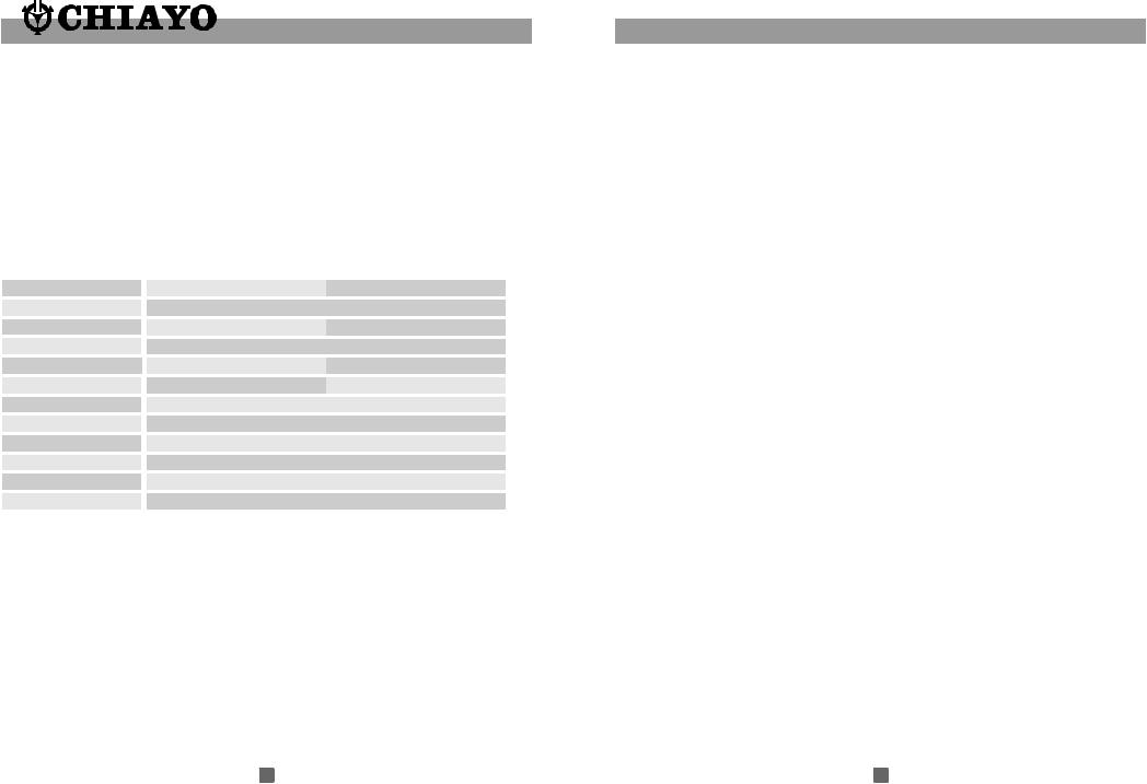
The following table gives an over view of the individual system.
System Overview
Model |
UDR-1000 |
UDR-2000 |
Frequency Band |
|
UHF |
No. of Channel |
1000 |
2*1000 |
Reception Mode |
|
Ture Diversity |
No. of Receiver |
1 |
2 |
AC Adapter |
12-15V / 800mA |
12-15V / 1500 mA |
Size |
|
19" |
Casing |
|
Metal |
Receiver LCD Color |
|
White in Blue LCD |
Handheld Transmitter |
|
UH-2000 |
Beltpack Transmitter |
|
UB-2000 |
Battery used in Transmitter |
|
AA * 2 |
4 If the Volume Control of the receiver is set too high, it may over-drive the input of the mixer, causing distortion. Conversely, if the receiver output is set too low, the overall signal to noise ratio of the system may be reduced. Adjust the output level of the receiver such that highest sound pressure level going into the microphone causes no input overload in the mixer, and yet permits the mixer level controls to operate in their normal range (not too high or too low ). This provides the optimum signal to noise for the entire system.
5 When inserting the batteries, please make sure that they are inserted according to the correct polarity.
6 For PLL frequencies agile version, before operation please make sure that the corresponding receiver MUST have the same frequency group and channel number as the transmitter.
7 Before making any channel change, please switch off the power supply. The synthesized program works in such a way that a change of channel will only take place after a power off and on action. Otherwise, the previously selected frequency will stay unchanged.
8 After making a channel change, please make sure that the corresponding change is made on the matching receiver also. To be exact, changes MUST be made at both the transmitter and receiver.
9 Use only brand new Alkaline batteries. Do not use " general purpose " batteries. When batteries are weak, replace the batteries altogether at the same time. Do not mix and use new and old batteries together.
10 Position the receiver so that it has the least possible obstructions between it and the transmitter. Line of sight is best!
11 The transmitter and the receiver should be as close as possible but not less than 1m.
12 A receiver cannot receive signals from two or more transmitters
simultaneously.
13 Turn the transmitter off when it is not in use. Remove the batteries if it is not to be used for a period of time.
1 |
14 |

REMARKS
RF Interference
If you encounter receiving interference (from other than an operating TV station), often it can be overcome by adjusting the receiver's squelch control, as described on below.
Please note that wireless frequencies are shared with other radio services. According to FCC requlations, wireless microphone operations are unprotected from interference from other licensed operations in the band. If any interference is received by any Government or non-Government operation, the wireless microphone must cease operation. The abovestatement is valid in the U.S.A.
Receiver Squelch setting
The squelch control setting is per LCD display on the front panel of the receiver is preset at the factory, but can be adjusted if you must use the system in a high RF interference area. If there is audio output from the receiver when your transmitter is OFF, adjust the squelch control so the system will receive the signal from your transmitter but squelch or eliminate the unwanted background RF noise. This adjustment can cause a reduction in usable range of the wireless transmitter, so set the control to the lowest position which reliably mutes the unwanted RF signal.
TIPS TO OBTAIN THE BEST RESULTS FOR A WIRELESS MICROPHONE SYSTEM
1 If external antenna is used, low loss RF shielded cable should be used and the length of the cable should not exceed 3m.
2 Do not place the receiver antenna within 1 m from another receiver or antenna. 3 The receiver antenna should be kept away from any metal surface.
Parts and functions
 UDR-1000 Receiver
1 |
|
|
|
2 |
3 |
4 |
5 |
|
10 |
11 |
12 |
13 |
14 |
15 |
|
6 |
67 |
68 |
96 |
|
|
|
16 |
17 |
|||||
|
MIC |
LINE |
BALANCED |
|
|
|
|
AC INPUT |
|
|
|
|
|
|
|
|
|
||
|
|
AF OUT |
|
|
|
|
|
|
|
|
DC IN |
|
|
12V - 15V |
|
ANT.B |
100V - 240V |
ANT.A |
1. |
Slot for front mount antenna 7. |
SET |
13. |
Unbalanced Out |
|
2. |
Power switch |
8. |
SCAN |
14. |
Balanced Out |
3. |
LCD Display |
9. |
USB port |
15. |
DC IN jack ( for certain market only ). |
4. |
UP button |
10. Slot for front mount antenna 16. |
AC IN jack ( for certain market only ) |
||
5. |
DOWN button |
11. Antenna B socket |
17. |
Antenna A socket |
|
6. |
MENU |
12. Mic / Line level Switch |
|
|
|
 UDR-2000 Receiver
1 |
2 |
3 |
4 |
5 |
10 |
11 |
12 13 |
18 |
2 |
19 |
|
|
|
6 |
67 |
68 |
69 |
|
20 |
21 |
22 |
23 |
|
24 |
25 |
26 |
|
MIC |
|
LINE |
BALANCED |
|
|
MIC |
LINE |
BALANCED |
|
|
|
|
|
||||
|
|
AF OUT |
|
|
|
|
AF OUT |
|
|
|
|
|
DC IN |
|
|
|
|
|
|
|
|
12V - 15V |
|
|
|
|
ANT.B |
|
|
|
|
|
|
|
|
14 156 16 176
27 28
AC INPUT |
|
100V - 240V |
ANT.A |
1. |
Slot for front mount Antenna |
11. LCD Display |
21. |
Unbalanced Out |
||
2. |
Power switch |
12. UP button |
22. |
Balanced Out |
||
3. |
LCD Display |
|||||
13. |
DOWN button |
23. |
DC IN jack |
|||
4. UP button |
||||||
14. |
MENU |
24. |
Mic / Line level Switch |
|||
5. |
DOWN button |
|||||
15. |
SET |
25. |
Unbalanced Out |
|||
6. |
MENU |
|||||
16. |
SCAN |
26. |
Balanced Out |
|||
7. |
SET |
17. USB port |
27. |
AC IN jack ( for certain market only ) |
||
8. |
SCAN |
18. |
Slot for front mount Antenna |
28. |
Antenna A socket |
|
9. |
USB port |
|||||
19. Antenna B socket |
|
|
||||
10. Power switch |
20. |
Mic / Line level Switch |
|
|
||
13 |
2 |
 Loading...