

Page 1
OPERATION MANUAL
Q-800 / Q-809 / M- 800 / M-809 (UHF)
Q-200 / Q-300 / M-2 00 / M-300 (VHF)
Page 2
General
Congratulation for owning this all-in-one portable sound system. Please read this
operating instruction thoroughly to fully understand its controls and functions.
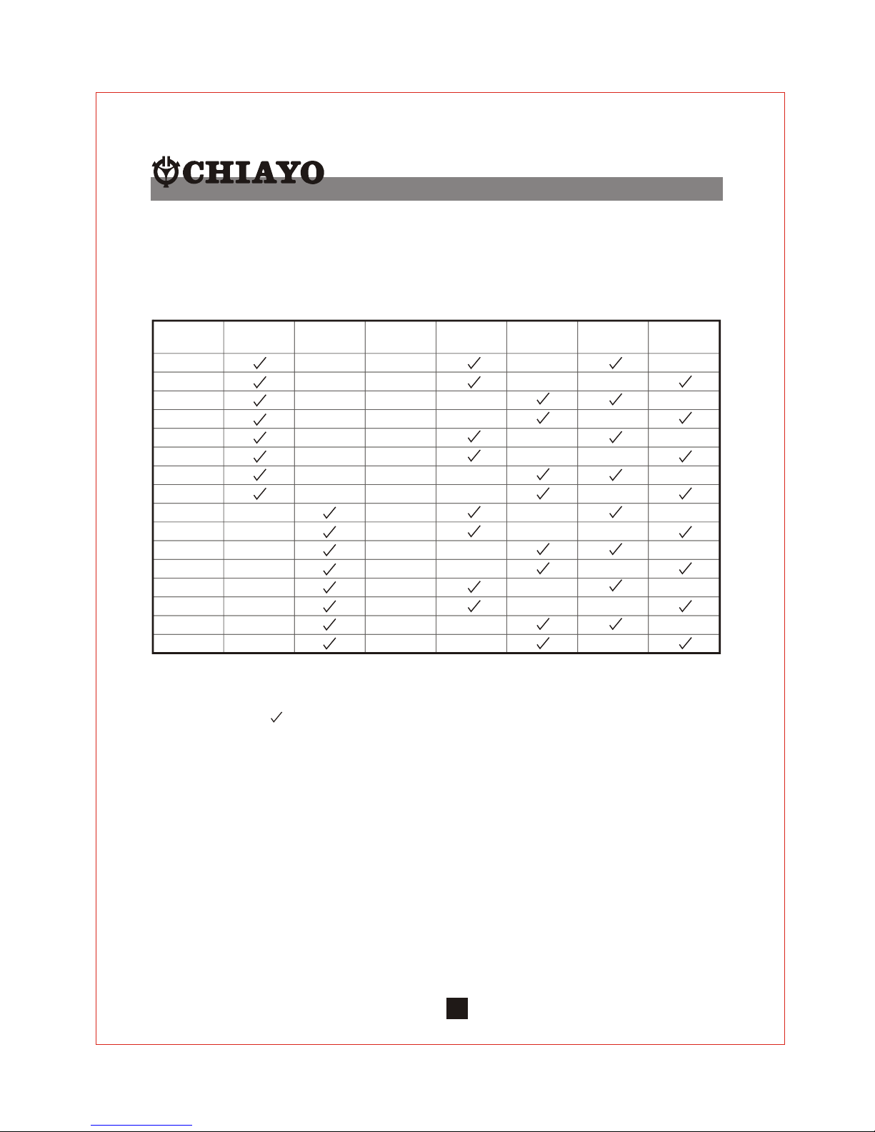
The following table gives an overview of the various Dynasty 1000 versions.
Legend
U : UHF : Yes
V : VHF : No
C : CD
T : TAPE
Example : U2CR denotes UHF 2 channel with CD and Rechargeable battery.
**CR denotes Dynasty 1000 without receiver modules.
Note : Manufacturer reserve the rights to change the above combinations without prior notice.
1
Models
U1CA
UHF VHF
CD
NO. OF
CHANNEL
TAPE
AC
BATTERY
U1CR
U1TA
U1TR
U2CA
U2TA
U2TR
V1CA
V1CR
V1TA
V1TR
V2CA
V2CR
V2TA
V2TR
X
X
X
X
X
X
X
U2CR
X
1
1
1
1
2
2
2
2
1
1
1
1
2
2
2
2
X
X
X
X
X
X
X
X
X
X
X
X
X
X
X
X
X
X
X
X
X
X
X
X
X
X
X
X
X
X
X X
X
X
X
X
X
X
X
X
X
Fig 1.
Page 3
2
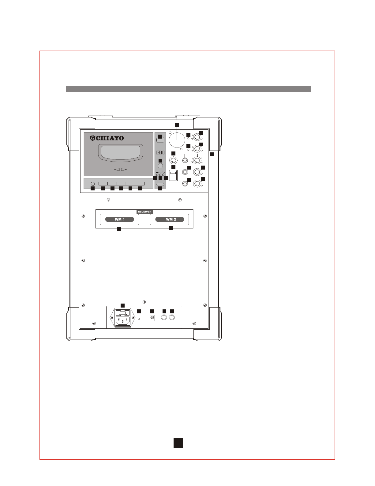
Rear panel configuration ( TAPE )
Fig 1.
1. MIC IN XLR/PHONE COMBO JACK
BALANCED/UNBACANCED
2. RF INDICATOR 1
3.
4.
5.
6.
7.
8.
9.
10.
11.MIC IN VOLUME CONTROL
12.
13.
14.
RF INDICATOR 2
RECEIVER WM 1 POWER SWITCH
AND VOLUME CONTROL
RECEIVER WM2 PWR SWITCH
& VOLUME CONTROL
LINE IN AND VOLUME CONTROL
CASSETTE DECK VOLUME
CONTROL
TONE CONTROL
LINE OUT
MASTER VOLUME CONTROL
MAIN POWER SWITCH
WIRLESS MODULE 1
WIRLESS MODULE 2
15.AC INPUT JACK
16.BATTERY STATUS INDICATOR
17.DC 24V INPUT
18.SPK OUT
19.SPK OUT (SWITCHED)
20.EJECT KEY
21.PITCH CONTROL
22.CONTINUOUS PLAY INDICATOR
23.ONE-TIME REVERSE
24.NON-REVERSE INDICATOR
25.MODE KEY
26.FAST FORWARD KEY
27.FORWARD PLAY KEY
28.STOP KEY
29.REVERSE PLAY KEY
30.FAST REVERSE KEY
31.RECORD KEY
1
2
3
4
5
6
7
8
9
10
11
14
15
12
161317
20
21
22
23
24
2526272829
18 1
9
3031
Page 4
3
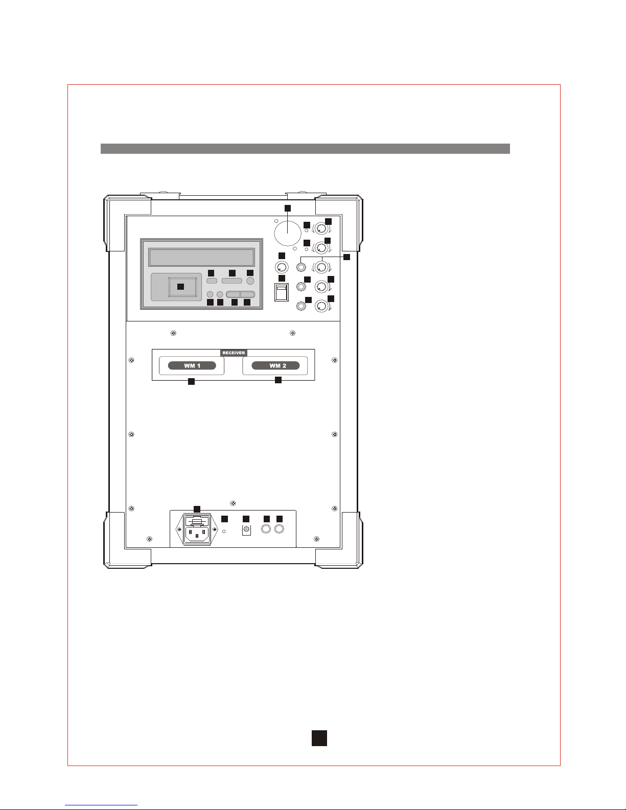
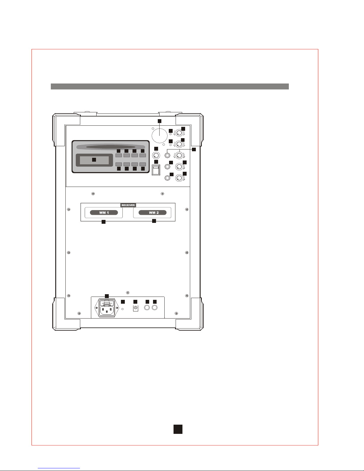
Rear panel configuration ( CD-1 )
21
20
23
24
22
Fig 2.
25
1
2
3
4
5
6
7
8
9
10
11
14
15
12
161317 18 1
9
2627
1. MIC IN XLR/PHONE COMBO JACK
BALANCED/UNBACANCED
2. RF INDICATOR 1
3.
4.
5.
6.
7.
8.
9.
10.
11.MIC IN VOLUME CONTROL
12.
13.
14.
RF INDICATOR 2
RECEIVER WM 1 POWER SWITCH
AND VOLUME CONTROL
RECEIVER WM2 PWR SWITCH
& VOLUME CONTROL
LINE IN AND VOLUME CONTROL
CD DECK VOLUME CONTROL
TONE CONTROL
LINE OUT
MASTER VOLUME CONTROL
MAIN POWER SWITCH
WIRLESS MODULE 1
WIRLESS MODULE 2
15.AC INPUT JACK
16.BATTERY STATUS INDICATOR
17.DC 24V INPUT
18.SPK OUT
19.SPK OUT (SWITCHED)
20.LCD DISPLAY
21.STOP
22.PLAY / PAUSE
23.OPEN / CLOSE
24.F. SKIP / FF
25.B. SKIP / REW
26.REPEAT
27.PROG
Page 5
4
Rear panel configuration ( CD-2 )
1
2
3
4
5
6
7
8
9
10
11
14
15
12
161317 18 1
9
1. MIC IN XLR/PHONE COMBO JACK
BALANCED/UNBACANCED
2. RF INDICATOR 1
3.
4.
5.
6.
7.
8.
9.
10.
11.MIC IN VOLUME CONTROL
12.
13.
14.
RF INDICATOR 2
RECEIVER WM 1 POWER SWITCH
AND VOLUME CONTROL
RECEIVER WM2 PWR SWITCH
& VOLUME CONTROL
LINE IN AND VOLUME CONTROL
CD CK VOLUME CONTROL
TONE CONTROL
LINE OUT
MASTER VOLUME CONTROL
MAIN POWER SWITCH
WIRLESS MODULE 1
WIRLESS MODULE 2
15.AC INPUT JACK
16.BATTERY STATUS INDICATOR
17.DC 24V INPUT
18.SPK OUT
19.SPK OUT (SWITCHED)
20.LCD DISPLAY
21.PROG.
22.SHUFFLE
23.STOP
24.PLAY / PAUSE
25.EJECT
26.REPEAT
27.SKIP / REW
28.SKIP / FF
20
20 21 22 23
24 25 26 27
Fig 3.
Page 6
5
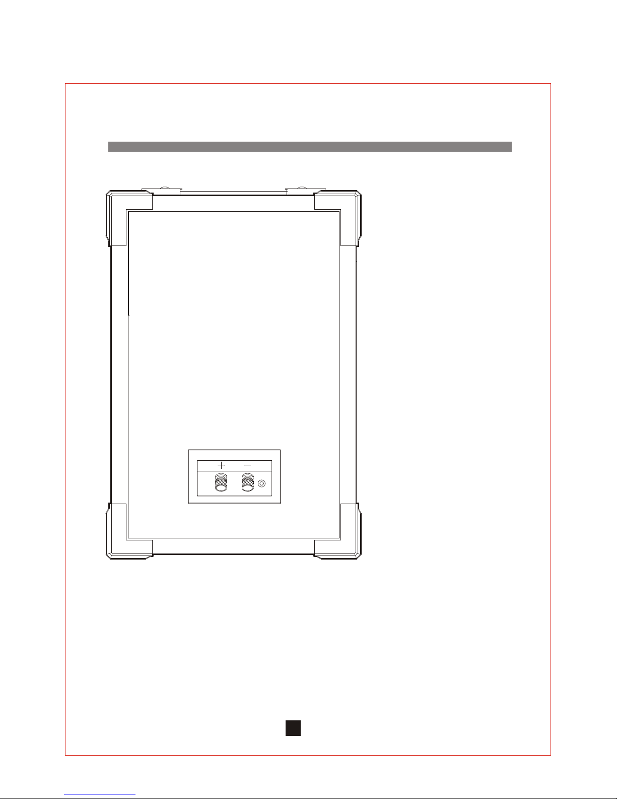
COMPANION SPEAKER
Fig 4.
Page 7

Rear panel configuration ( Fig. 2, 3, 4 & 5 )
The rear panel is divided into two different segments or modules as follow :
Cassette Recorder or CD player Module
Cassette Recorder Module ( Fig. 2 )
1.Eject key
2.Counter
3.Variable Speed Control
4.Auto Reverse indicator
5.Single reverse indicator
6.Single side indicator
7.Mode selector
8.Fast Forward
9.Forward play
10.Stop
11.Reverse play
12.Fast Reverse
13.Record
A.CD Player module ( Fig. 3 )
1.Display indicator
2.Stop
3.Play / Pause
4.Open / Close
5.F. Skip / FF
6.B. Skip / Rew.
7.Repeat
8.Prog.
Remark : For car CD version, please refer to the operating manual of the individual unit
from the manufacturer.
6
Page 8

The Power Supply and basic Battery Management.
The power supply of Dynasty 1000 system comes from the two pieces of 12V /
4.5 AH built-in rechargeable batteries ( maintenance free Lead Acid type,
which has no memory effect ) . An understanding and knowledge of
rechargeable battery is imperative in the operation of the portable sound
system as it helps to give a trouble-free operation of this system.
After unpacking the unit for the first time, please charge the rechargeable
batteries in the system first for at least 10 hours before any operation. This is a
very important procedure that user MUST undertake in order to get the longest
life span out of the batteries. Failure to follow this proper battery management
instruction may cause the user end up paying for new batteries.
The rechargeable batteries were fully charged in the factory before shipment.
However, the unit you have just unpacked could have been several months old
and the built-in lead acid rechargeable batteries might have been
discharged or drained. This is analogue of car which has been left unused for
months and the restart is impossible due to flat battery. It is thus imperative that
a full charge is absolute necessary for a new system or system left unused for
several months.
To charge the battery, simply plug in the AC supply and the charging process
will start automatically and the battery status indicator ( 16 ) will flash. When
permanent Green light appears, it means the batteries are fully charged.
Normal operation could now be resumed. When the charging indicator ( 16 )
lights up in RED, it means battery is weak and charging is required. In an urgent
case when the system must be used while the system is still under charging, for
this system it is still possible as the AC power supply is designed such that it also
provide the power for the system while charging the batteries but this could
only be done when the charging process has started for at about 5 minutes
and some minimum energy has been stored in the batteries.
7
Page 9

Operating the Wireless Microphone System.
To use the First wireless system, switch on the receiver module power supply switch WM1(4) .
Switch on the corresponding matching transmitter or handheld microphone ( please refer
to the operating instruction of the individual transmitter ). When RF signal is being received
by the receiver, the receiver RF signal indicator 1 ( 2 ) will light up. Rotate the control
WM1 ( 4 ) and MASTER volume control ( 10 ) clockwise to increase the volume. When
voice is spoken into the microphone, amplified sound should be heard over the built-in
speaker.
This instruction is for system which is equipped with two wireless receiver modules, To use
the Second wireless system, switch on the receiver module power supply switch WM2 ( 5 ).
Switch on the corresponding matching transmitter or handheld microphone. When RF
signal is being received by the receiver, the receiver RF signal indicator 2 ( 3 ) will light
up. Rotate the WM 2 control ( 5 ) and MASTER volume control ( 10 ) clockwise to increase
the level. When voice is spoken into the microphone, amplified sound should be heard
over the built-in speaker.
Operating the Wired / Cable Microphone
To use the wired microphone, simply plug in the wired microphone connector into the XLR
/ Phone jack combo connector ( 1 ) . This unique connector accept either XLR or 1/4
Phone Jack male connector. Rotate the MIC In volume control ( 11 ) and MASTER Volume
control ( 10 ) clockwise to increase the volume. When voice is spoken into the wired
microphone, amplified sound should be heard over the built-in or external speaker.
To use a second wired microphone, simply plug in the wired microphone cable
connector into LINE IN ( 6 ). Rotate the volume control ( 6 ) and MASTER volume control
clockwise to increase the volume. When voice is spoken into the wired microphone,
amplified sound should be heard over the built-in or external speaker.
Both wired and wireless microphone could be used simultaneously as there is a built-in
mixer to mix both input signals.
When all the levels are set, simply use the MASTER volume control ( 10 ) as main control.
Function of Speaker out
There are two types of Speaker out jack.
Speaker out ( unswitched ) (18 ) When an external speaker is connected to this output,
both the internal speaker of and the external speaker will have sound.
Speaker Out ( switched ) ( 19 ) When an external speaker is connected to this output, the
internal speaker will be muted and only the external speaker will have sound.
8
Page 10
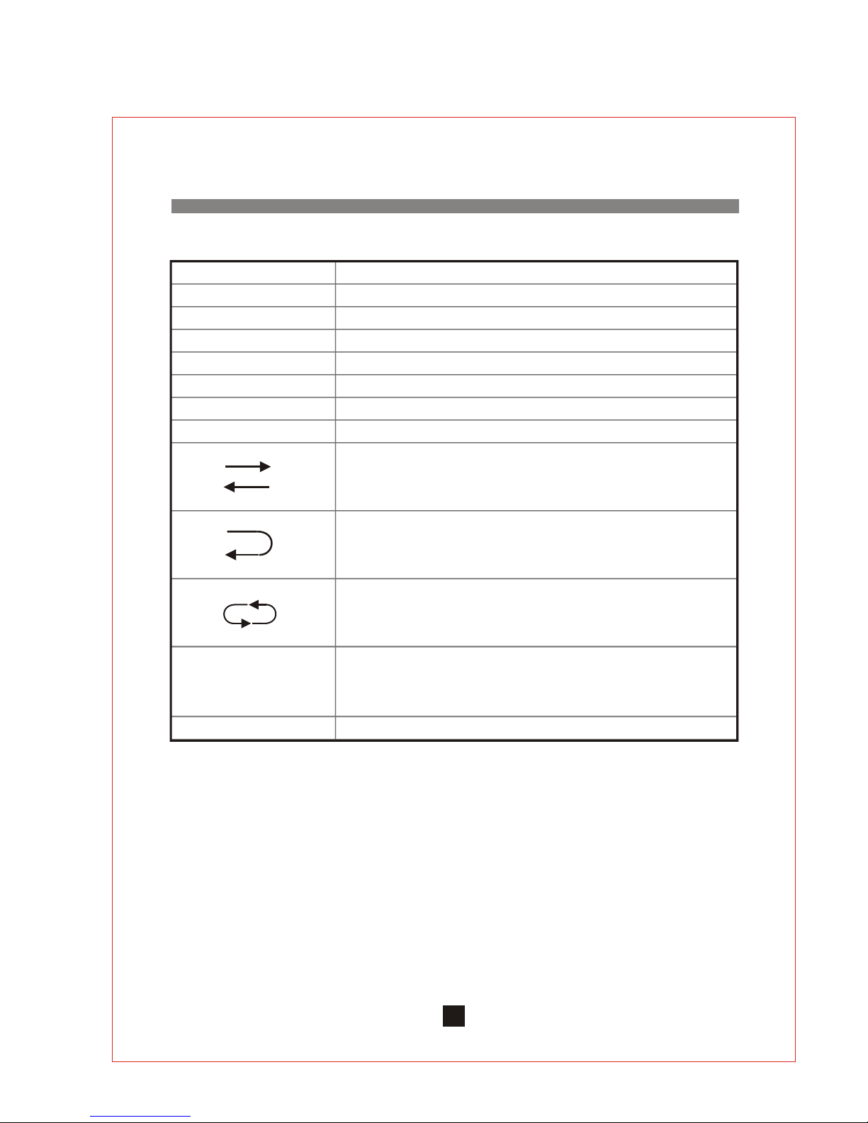
Operating the Cassette Recorder
Keys Functions
FF Fast Forward Press this key for fast for ward .
Press this key for play in forward direction.
FP Forward Play
Press this key to stop the tape.Stop
Press this key for play in reverse direction.RP Reverse Play
Press this key for fast reverse.
FR Fast Reverse
Record
Press this key together with FP or RP key for recording.
Mode selector This key is pressed to select one of the following three modes.
Active in Forward nor Reverse direction, the cassette tape will
play to the end and stop automatically. This mode may be
used for Record and Play.
The cassette tape will play to the end, stop, reverse direction to
the end of the second side and stop. This mode may be used
for Record and Play.
This mode provides continuous Play operation. It is not operable
in Record mode, however, it will record one complete cycle if
the recording is begun in the Forward direction.
Normal tape speed at center position. Clockwise direction
increases tape speed. Counter-clockwise direction reduces
tape speed.
Eject
This key is pressed for ejecting the tape.
Speed Control
Rotate the volume control knob ( ) of the TAPE / CD control panel to adjust the volume
of the Cassette deck. For Bass and Treble setting , adjust Bass / Treble control knob ( ) .
Clockwise direction from center line is for increased Treble and counter-clockwise
direction from center line is for increased Bass.
9
Page 11
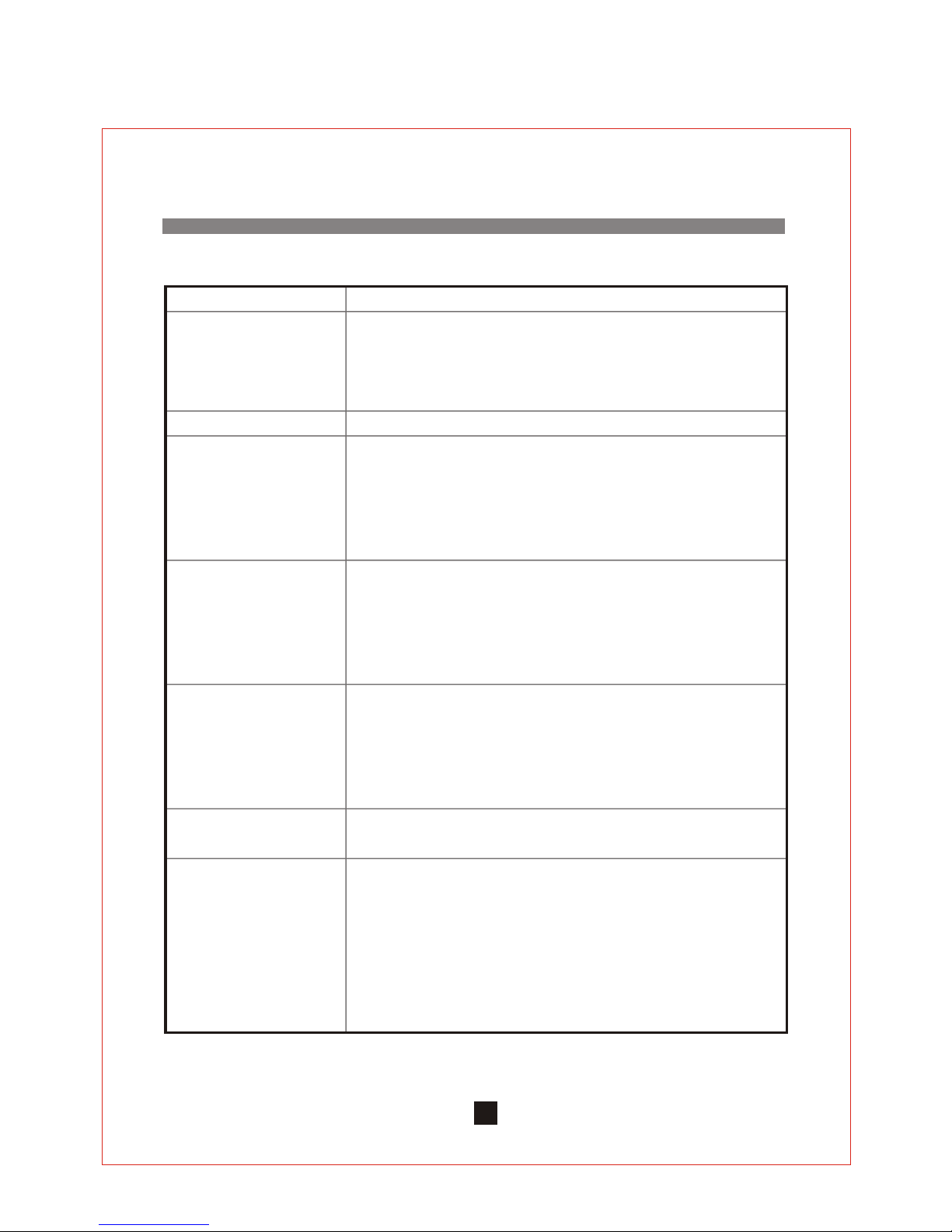
Keys Explanation
When it is pressed during STOP, PLAY will start after track search.
When it is pressed during PLAY, it will change to PAUSE and the
word PLAY flashes.
When it is pressed during PAUSE, it will change to PLAY.
PLAY / PAUSE
STOP When it is pressed at PLAY mode, CD will STOP.
When CD is STOP, pressed this key once to decrease one track.
When CD is in PLAY mode, press this key for < 1/2 second will
make it search backward one track.
When CD is in PLAY mode, press this key for >1/2 second will
make it to execute FR Fast Reverse function.
B-SKIP / REW
When CD is STOP, pressed this key once to increase one track.
When CD is in PLAY mode, press this key for <1/2 second will
make it search forward one track.
When CD is in PLAY mode, press this key for >1/2 second will
make it to perform the FF Fast Forward function.
F-SKIP / REW
If this key is pressed in cyclical sequence, REPEAT mode will
change as follow :
REPEAT : repeat the same track.
ALL REPEAT : repeat all tracks.
: repeat off
REPEAT
When this key is pressed at either PLAY or STOP mode,
door will move in and out cyclically.
OPEN / CLOSE
Programming procedures :
First press STOP, then press PROG key, PROG and 00 will flash.
Select the track by pressing B-SKIP / REW or F-SKIP / FF key to
select the desired track and then press PROG again to store.
00 will flash, select the second track to be stored. This could
be repeated to store a few programmed track. Press PLAY to
perform the programmed tracks.
Press STOP again to clear the programming.
PROG
Rotate the volume control knob ( ) of the TAPE / CD control panel to adjust the volume of
the Cassette deck. For Bass and Treble setting , adjust Bass / Treble control knob ( ) .
Clockwise direction from center line is for increased Treble and counter-clockwise direction
from center line is for increased Bass.
10
CD-1 CONTROLS
Page 12
PROG Program button. Select the desired song. To store the ,
Press ENTER key.
11
CD-2 CONTROLS
SHUFFLE
Pressing of this key will pick and play the song in random
STOP When it is pressed at PLAY mode, CD will STOP.
PLAY / PAUSE When it is pressed during STOP, PLAY will start after track search.
When it is pressed during PLAY, it will change to PAUSE and the
word PLAY flashes.
When it is pressed during PAUSE, it will change to PLAY.
EJECT
REPEAT
ENTER
B-SKIP / REW
F-SKIP / FWD
When CD is STOP, pressed this key once to decrease one track.
When CD is in PLAY mode, press this key will
make it search backward one track.
When CD is in PLAY mode, press this key longer will
make it to execute FR Fast Reverse function.
When CD is STOP, pressed this key once to increase one track.
When CD is in PLAY mode, press this key will
make it search forward one track.
When CD is in PLAY mode, press this key longer will
make it to perform the FF Fast Forward function.
This CD player is using a suction mechanism to suck in the disk when power is switch on.
Press this key to eject the disk,
Please REPEAT in PLAY mode will repeat the song. Press ENTER in
PROG. will store the song.
Page 13

12
Add on a second receiver module
This instruction is for a system which is delivered without the 2nd receiver module and
you need to add on the 2nd module.
First, unscrew and remove the cover of the RECEIVER panel. Push in the 2nd module to
the right hand slot mark WM2. Before inserting this module, please verify that :
1.The 2nd module MUST be of the same frequency band ( VHF or UHF ) as the 1st module.
The pre-installed antenna of the 2nd module is of the same band as that of the 1st
module. Plugging in a 2nd module of a different band will severely affect the
performance due to unmatched antenna !
2.The frequency of the 2nd module MUST be from the non-interference list recommended
by Chiayo.
3.It is advisable to plug in the same type of receiver as the 1st one to get the same
performance. This is to say that if the 1st module is using a diversity receiver, it is
nd
advisable that the 2 module should use a diversity receiver vice versa.
Simple DIY Trouble-shootings:
1. No sound when one speaks to the wireless microphone
Please verify the followings :
1.1 Main power switch should be ON. When no light appear, it means that the batter y is
weak. Please plug in the AC cable to charge the battery.
1.2 WM1 ( 4 ) should be switched on. When two wireless microphones are used, both
WM1 (4) and WM2 ( 5 ) should be switched on. When this is done, please verify that
the MASTER volume control ( 10 ) is been used to adjust to the desired volume.
1.3 Wireless microphone should be put to ON and verify that the battery is O.K. ( please
refer to wireless microphone operating manual ) and observe the RF signal received
on the RF indicator ( 2 ) or ( 3 ).
1.4 Please verify that the frequency on the wireless microphone and the corresponding
built-in wireless receiver module are exactly the same.
2. No sound when CD player or Cassette Recorder is used.
2.1 Main power switch should be ON. When no light appear, it means that the batter y is
weak. Please plug in the AC cable to charge the battery.
2.2 Please make sure that TAPE / CD volume control ( 7 ) and MASTER volume control ( 10 )
are turned on.
2.3 Follow the proper operating instruction of CD and Cassette recorder.
No power supply
1.Battery is faulty
2.Battery is not charged.
Page 14
Specification
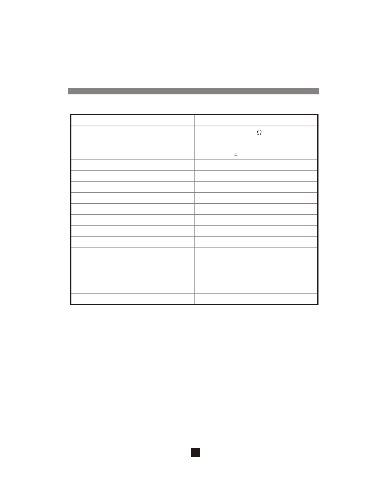
Item Specification
Max. Power Output
Distortion
Frequency Response
Input
Speaker System
Power Supply
Recharge Time
Receiver Module
Wired microphone
Wireless microphone
Output
Dimension
Weight
Max. 50 W ( RMS ) / 4 Load
< 0.5%
50Hz - 20KHz 3db
Wired Mic / Line In
6 * 9 " full range
120 V / 230 V AC 3A or 24 - 35 V DC
10 Hour
UHFor VHF band
Chiayo or other compatible brand
Handheld / Lavalier / Headset
Speaker/ Speaker out(switched)/ Line out
440 * 210 * 250 mm
18.5 Kgs ( with Cassette Recorde )
19.5 Kgs ( with CD player )
Color
Black
13
Mic In
XLR / Phone Conbo jack * 1
Page 15
Battery
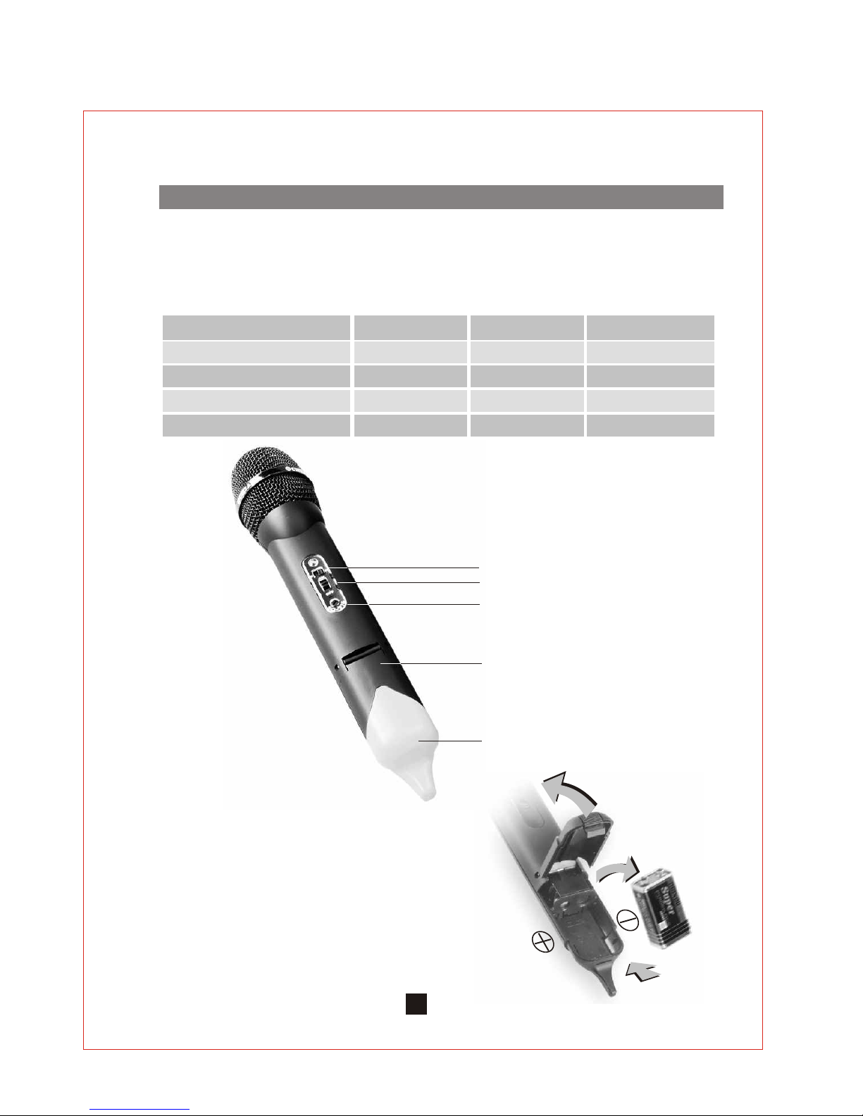
Q-200 / Q-209 / Q-800 / Q-809 use a 9V battery for
power. To change or replace the battery, Please
remove the color cap first, then press at the bottom
of battery compartment to release the cover as
shown in right figure.
Model Band Channel selector
Q-209/Q-300
Q-809
Q-800
VHF
UHF
Fixed Frequency
Fixed Frequency
No
No
Sensitivity switch
Power Switch
Channel Selector
( for SQ version only )
Battery compartment
Channel
Color Cap
Press
UHF
Fixed Frequency
No
Q-200 VHF Fixed Frequency
No
General
Hand-Held Microphone
14
Four different handheld microphones ( see table below ) share this operating manual together,
please go through it thoroughly before operation.
Page 16
Sensitivity Switch
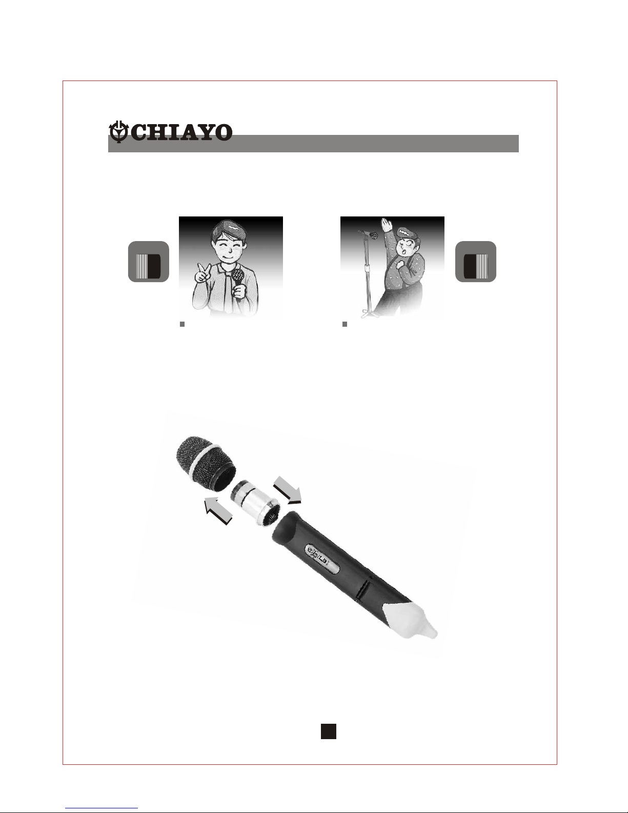
These microphones have a sensitivity switch, For close mouth singing or normal speech
please put the switch to N (normal) position. For tripod-mount speech, please put the switch
to H (high) position.
SENS
H
Changing of capsule
These microphone have a module design. To change or replace a capsule, Open the grill to
pull out and plug in the capsule as shown in the following figure.
N
Low Sensitivity High Sensitivity
SENS
H
N
15
Page 17
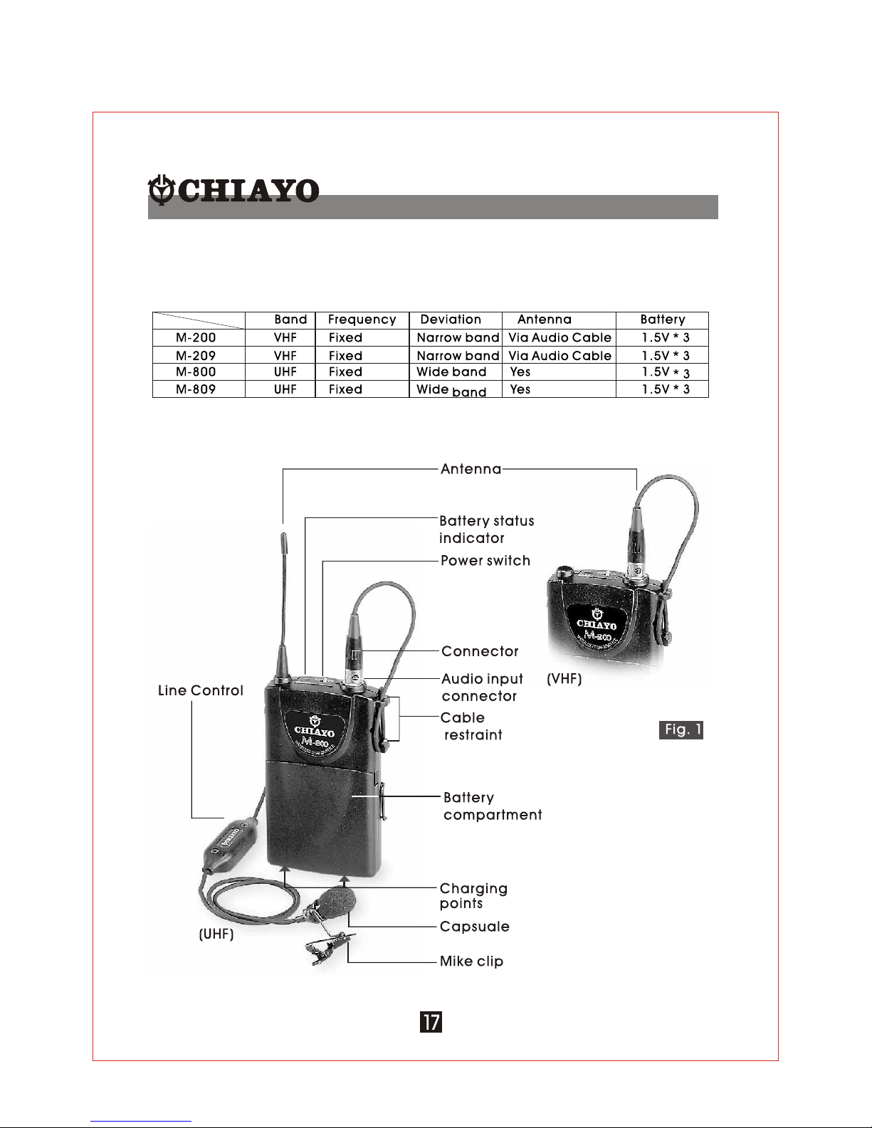
Before operation, please check and make sure that transmitter & receiver are of
matching frequency or frequency group (for PLL version). For PLL version, further verify
that the channel selected at both ends are of the same.
To switch on the microphone, put the switch to "ON" position. The green LED indicator
will light on indicates that battery is fresh. When RED LED light on indicates that battery
is weak, thus a replacement is necessary.
For best result, alkaline battery is recommended. Please remove the battery if the
transmitter is not to be used for a longer period.
When necessary, mic capsule could be replaced by pulling out and plugging in the
new one, either dynamic or condenser.
For close mouth singing or speaking, put the sensitivity switch to N (Normal) and for
tripod mouth application, where the speaker stands at a distance away, put the
sensitivity switch to H (High). Be careful to put back the sensitivity switch to N for close
mouth singing as H (High) sensitivity for close mouth application might cause distortion.
When holding the handheld mic, please do not hold the antenna part of it as this
might severely affect the efficiency of the transmission range.
16
Operating instructions
Page 18
Belt-Pack Transmitter
Four different transmitters ( see table below ) are sharing this operating manual, please go
through it thoroughly before operation.
The basic operations of all the above transmitters are almost the same. However, sometimes
they use different connectors to suit different requirements.
Page 19
Installation of batteries
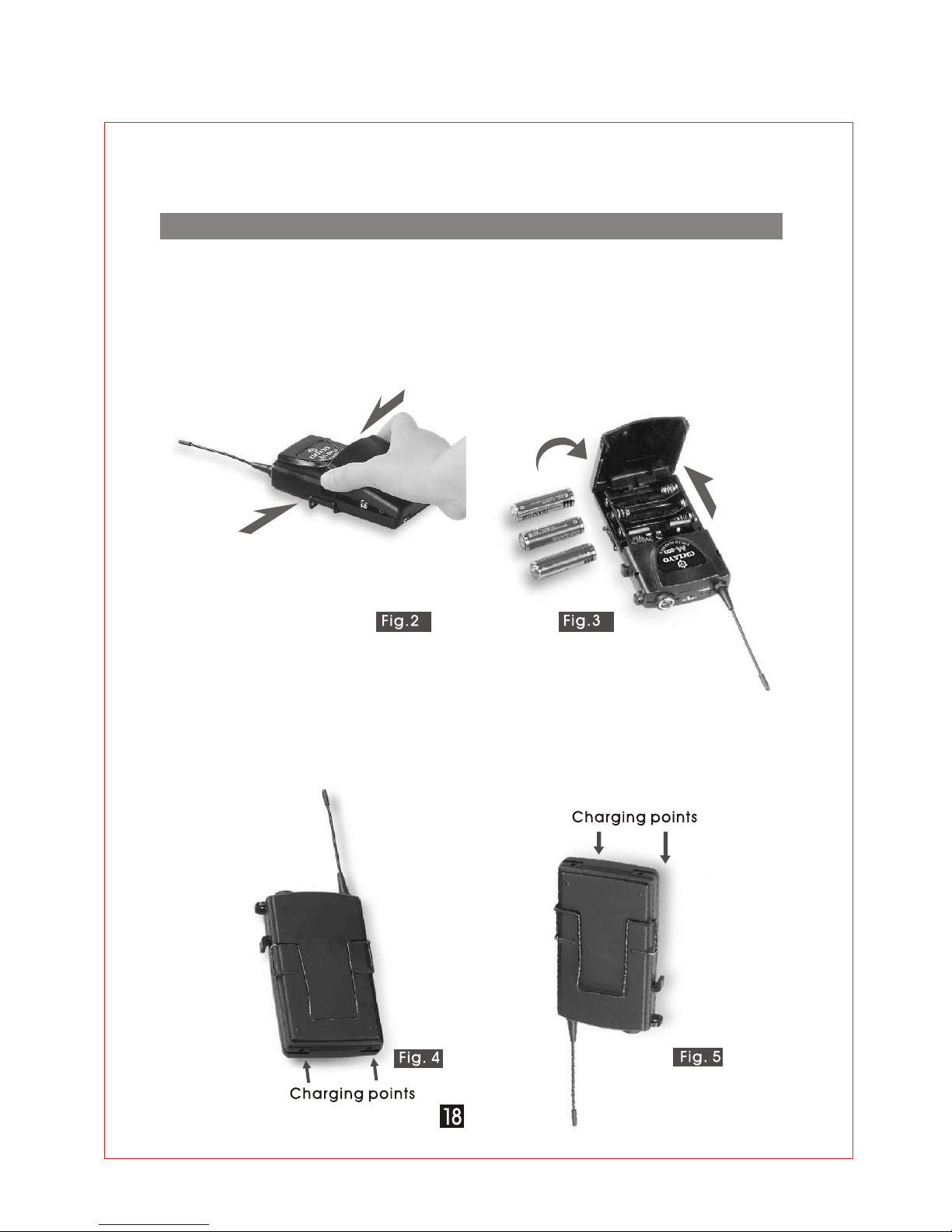
This transmitter uses 3 pieces of " A A " size batteries (Alkaline battery is recommended ). To
install or remove the batteries, press the release buttons at the edges of the transmitter to
open or close the cover as illustrated ( Fig.2 ). When installing the batteries with the cover
open toward you, the cover might block your hand. It is thus recommended that while
inserting or removing the batteries you should hold the transmitter in such a way that the
cover open a way from you. ( Fig.3 )
Installation of Belt-clip
This specially designed detachable belt-clip allows the user to wear the transmitter with
antenna pointing upward or downward as illustrated. To wear the transmitter with the
transmitter pointing upward, install the belt-clip as in Fig.4. To wear the transmitter with the
antenna pointing downward, please install the belt-clip as in Fig,5.
Page 20
1
1
2
2
3
3
4
4
Installation of Lavalier / Headset microphones or
instrument
inputs.
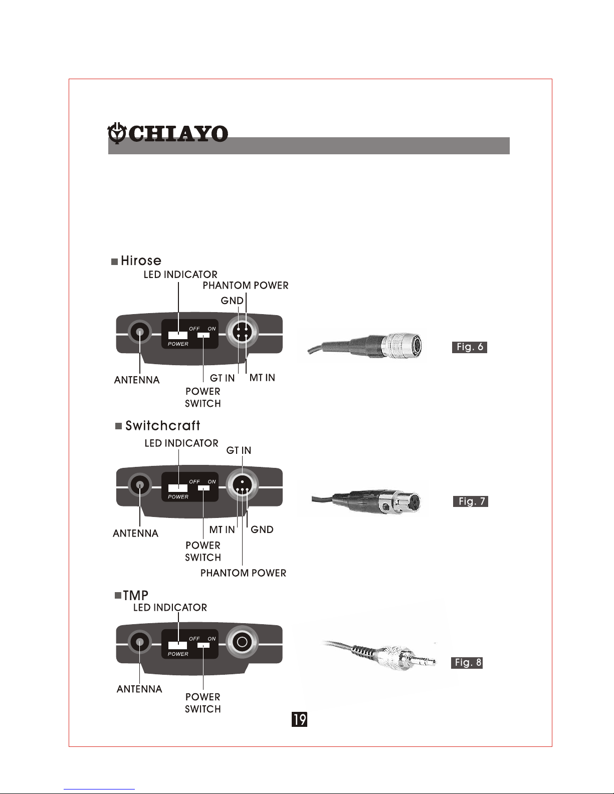
Depending on customer requirements, Lavalier / Headset microphone or instrument inputs
could be connected to the transmitter via the audio input connector. User is free to choose
the various input sources but is advised to take note that connector used must be
compatible to each other. The pin configurations of various connectors are as follow ( Fig.6
& 7 & 8 ).
Page 21
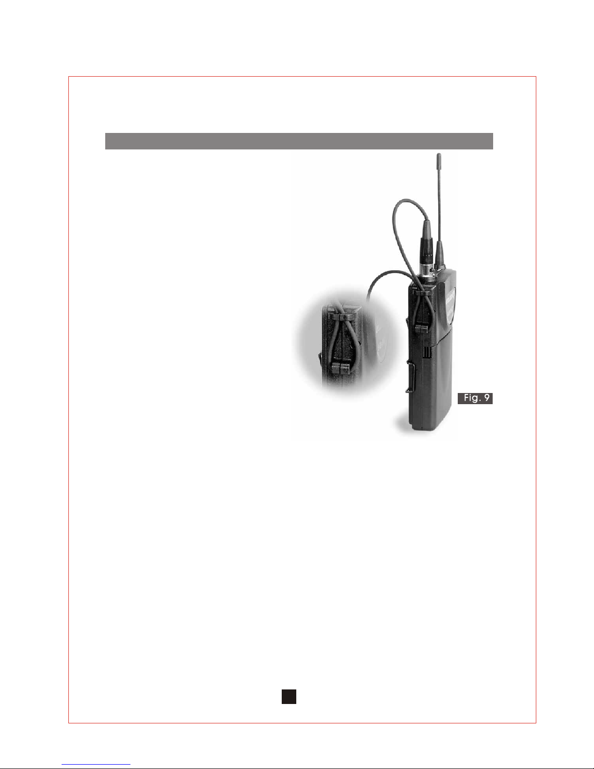
Installation of cable restraint
To prevent contact noise caused by constant tension
applied to the connector,, a cable restraint is designed such
that tension is totally reduced when it is properly used ( see
Fig.9 ).
When the audio cable go through the cable restraint, it
could prevent sweat from going diectly into the electronic
board via the connector. This is another advantage of the
cable restraint.
20
Page 22
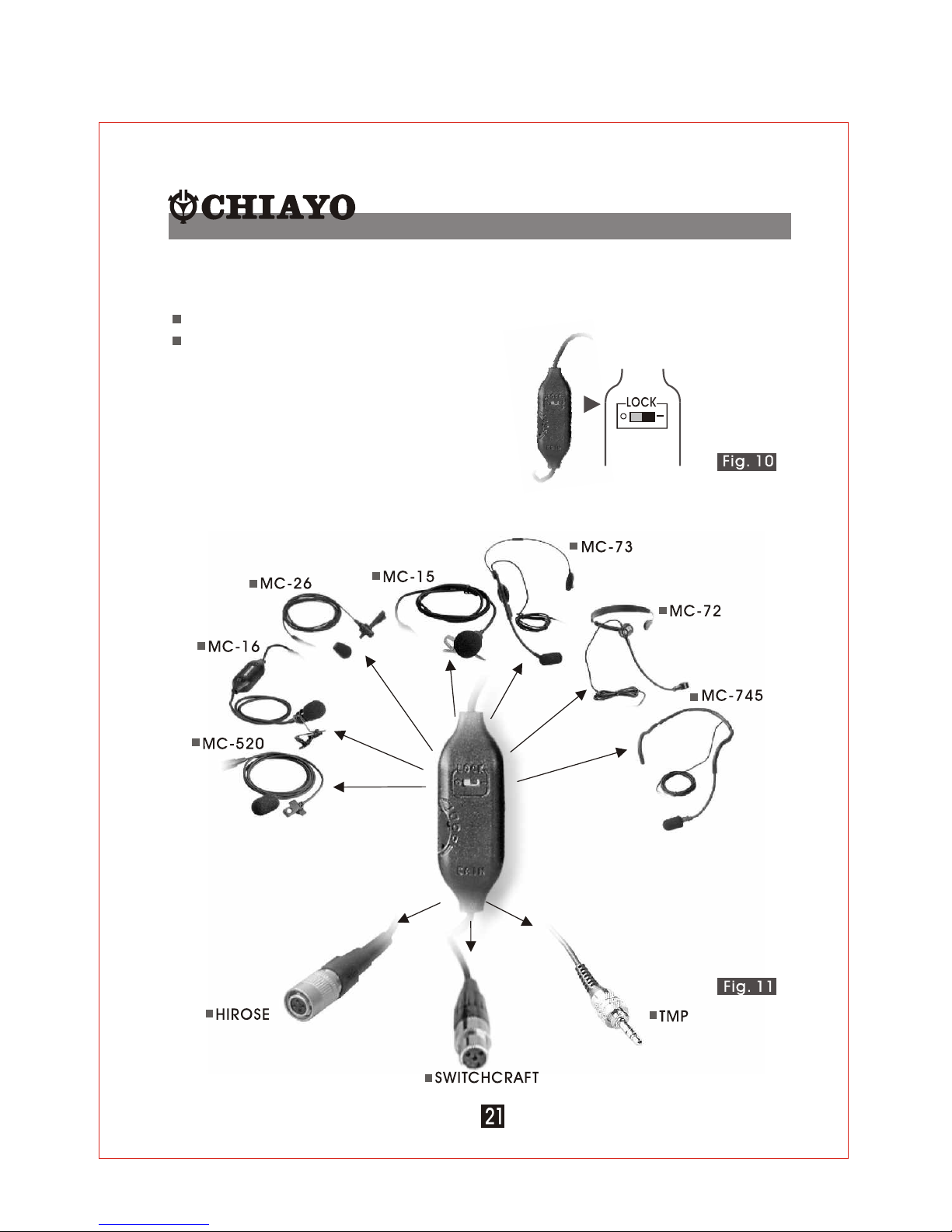
Line Control
This is a Chiayo unique Line Control. The purpose of the L ine Control is to control :
Max. gain before feedback
Remote control of the Gain
There is another advantage of the Line Control as it could serve as an adapter between
different Lavalier / Headset and connectors as illustrated below. ( Fig.11 )
The Line Control is designed such that when Max.
Gain before feedback is achieved, a disable switch
could lock out the function of the Line Control to
prevent accidental adjustment of the control.
(Fig.10 )
Page 23

Caution and tips on how to obtain the best results.
1.Before inserting the batteries, please make sure that they are inserted according to the
correct polarity.
2.For PLL 16 frequencies agile version, before operation please make sure that the
corresponding receiver MUST have the same frequency group and channel number as the
transmitter.
3.For fixed frequency version, before operation please make sure that corresponding
receiver MUST have the same frequency as the transmitter.
4.Before making any channel change, please switch off the power supply. The synthesized
program works in such a way that a change of channel will only take place after a power
off and on action. Other wise, the previosly selected frequency will stay unchanged.
5.After making a channel change, please make sure that the corresponding change is
made on the matching receiver also. To be exact, changes MUST be made at both the
transmitter and receiver.
6.The audio cable of M-200 and SM-216 also serve as antenna. The length of the cable is cut
according to the specific frequency range. Do not alter the length or mix around the cable
of different transmitters. The use of wrong audio cable will affect the antenna efficiency of
the transmitter!
7.Use only brand new Alkaline batteries. Do not use " general purpose " batteries. When
batteries are weak, replace the three batteries altogether at the same time. Do not mix
and use new and old batteries to gether.
8.Position the receiver such that it has the least possible obstructions between it and the
transmitter. Line of sight is best!
9.The transmitter and the receiver should be as close as possible but not less than 1m..
10.A receiver cannot receive signals from two or more transmitters
simultaneously.
11.Turn the transmitter off when it is not in use. Remove the batteries if it is not to be
used for a period of time.
Input Level Gain Control Adjustment
Low impedance ( Lo-Z ) " MT" & high impedance ( Hi-Z ) " GT" gain controls are situated inside the
transmitter as shown in Fig 10. Gain controls are adjustment ports that enable you to use microphones of
differing output levels and Guitar or instruments with Hi-Z output. To adjust microphone ( Lo-Z ) input levels,
turn the " MT" control and to adjust the Guitar or instrument ( Hi-Z ) input, adjust the " GT" gain control to set
the transmitter's desired audio input level.
Page 24
 Loading...