

Page 1
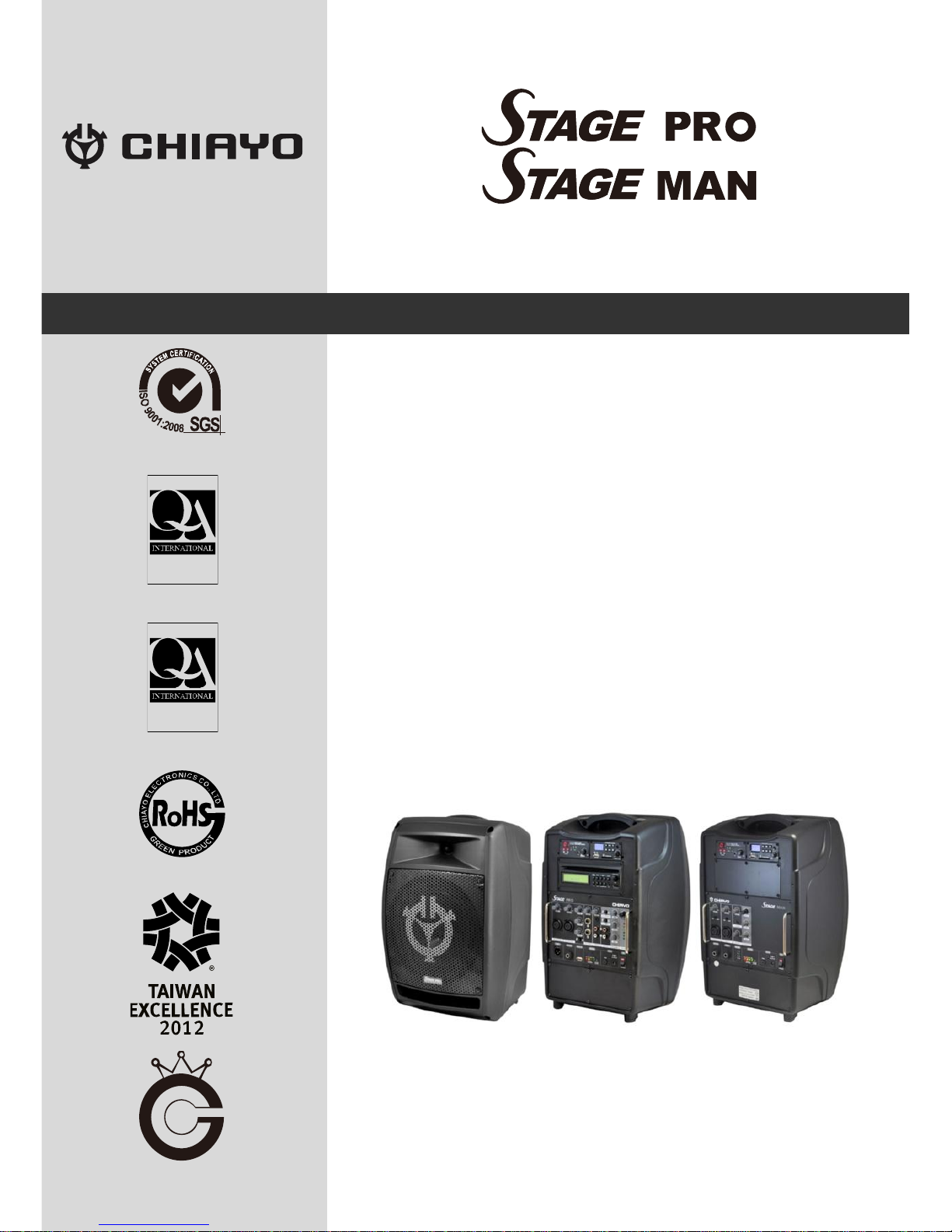
Multifunctional Wireless Mixer Amplifier System
ISO 9001
ISO 14001
OHSAS 18001
GREEN PRODUCT
World Genius Convention
Silver Medal
Operation manual
IS O
14 0 0 1
RE GIST ERE D
O H SA S
18 0 0 1
RE GIST ERE D
Page 2
-1-
Please read and follow the instructions in this manual thoroughly to obtain optimum results
from this unit. We also recommend that you keep this manual handy for future reference.
Safety Precautions
Be sure to read the instructions in this section carefully before use.
Make sure to observe the instructions in this manual as the conventions of safety symbols
and messages regarded as very important precautions are included.
Safety symbols and messages described below are used in this manual to prevent bodily injury
and property damage which could result from mishandling. Before operating your product, read
this manual first and understand the safety symbols and messages so you are thoroughly
aware of the potential safety hazards.
WARNING
Indicates a potentially hazardous situation which, if mishandled,
could result in death or serious personal injury.
CAUTION
Indicates a potentially hazardous situation which, if mishandled,
could result in moderate or minor personal injury, and/or property
damage.
Make sure to observe the following handling precautions so that a fire or personal injury does
not result from leakage or explosion of the battery.
Do not short, disassemble, heat or put the battery into a fire.
Never charge batteries of the type which are not rechargeable.
Do not solder a battery directly.
Be sure to use the specified type of battery.
Note the correct polarity when inserting a battery in the unit.
Avoid locations exposed to the direct sunlight, high temperature and high humidity when
storing batteries.
WARNING
To prevent the electromagnetic wave from badly influencing
medical equipment, make sure to switch off the unit's power when
placing it in close proximity to the medical equipment.
CAUTION
Battery discharge naturally according to a certain pattern even not
in use. For best performance and a prolonged lifespan, battery
should be charged regularly after every use or every month when
the system is in storage and not being used!
CD player optical pick up head is a very delicate device and
sensitive to humidity. Please avoid using it in high humidity area
to avoid damage! .
Page 3
ISO 9001|ISO 14001|OHSAS 18001
-2-
Congratulations and thank you for purchasing this all-in-one portable sound system. To ensure
a trouble-free operation, please read the manual thoroughly to fully understand its controls and
functions.
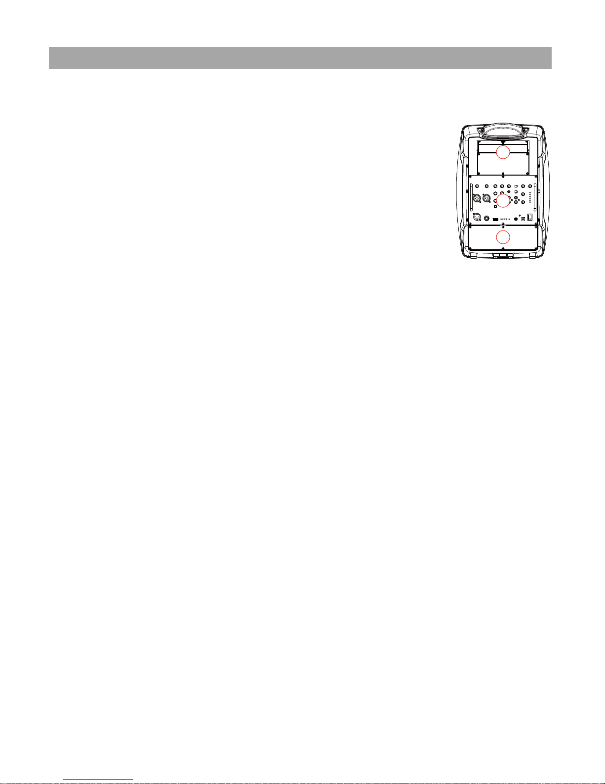
The rear panel of these portable sound systems is divided into 3 sections:
1. The Module compartment
2. The Control Unit compartment
3. The Battery compartment
The Modules Compartment can be user configurable and user can access
the battery compartment to change battery.
Without the CD player, all the versions herein can be configured with up to 4 modules, among
which one can be repeater transmitter/MP3/Bluetooth module.
However, when CD is installed, only two module slots will be freed and available.
The wireless receiver/transmitter module is in the UHF PLL synthesized type with 16 or 100
preset frequencies. Some receivers are equipped with IrDA 2-ways synchronization.
Configuration
STAGE PRO / STAGE MAN may come equipped with the following:
1. AC power cord
2. 1~4 or no wireless receiver/transmitter/MP3/Bluetooth module(s).
3. 1~4 transmitters, either handheld or belt-pack transmitter (except version with no module
installed).
Optional accessories
1. Weather proof dust cover.
2. Single trolley bag/Dual trolley case
3. Tripod stand
4. Companion active powered speaker (Slave speaker for STAGE PRO)
5. Companion passive speaker (external speaker for STAGE MAN)
6. Wired microphone.
Remark
STAGE PRO is a 2-way speaker system with electronics crossover, one can NOT connect a
passive speaker to this system as external speaker. Instead, active powered speaker should be
used (either wired or via wireless link) as external speaker for STAGE PRO!
STAGE MAN is a full range coaxial speaker system, its amplifier is capable of driving a passive
external speaker via Speaker OUT and the external speaker used MUST be a passive one!
Specifications are subject to change without prior notice.
1
2
3
Page 4
-3-
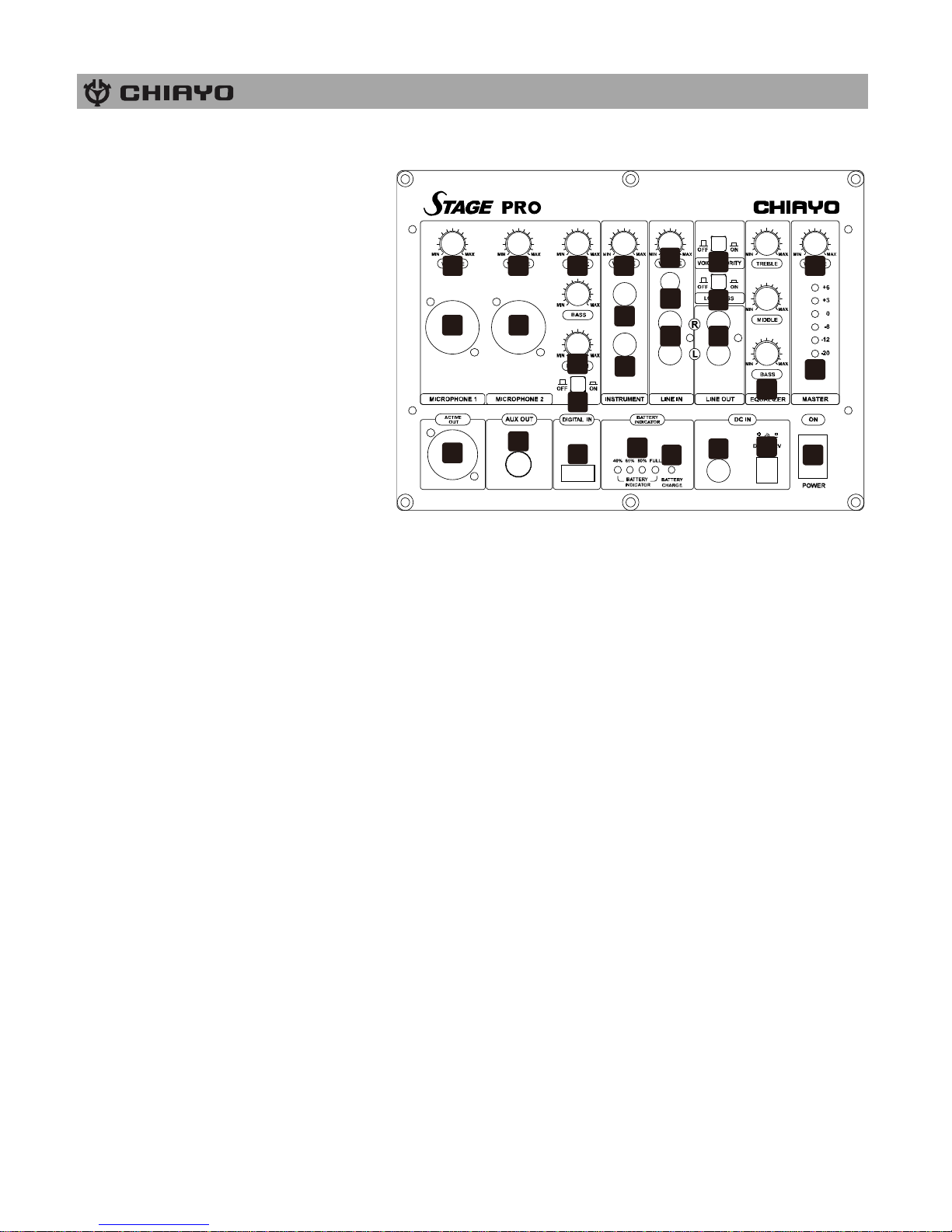
Parts and functions on STAGE PRO control panel
1. Mic in #1
2. Mic #1 volume control
3. Mic in #2
4. Mic #2 volume control
5. Mic tone control (Treble/Bass)
6. Reverb volume control
7. Reverb on/off
8. Instrument in #1
9. Instrument in #2
10. Instrument volume control
11. Line in (3.5mm)
12. Line in (RCA R/L)
13. Line in volume control
14. Line out (RCA R/L)
15. Loudness on/off
16. Voice priority on/off
17. Music tone control (Treble, Middle, Bass)
18. Master volume control
19. Master Limiter indicator
20. Audio link out
21. Aux out/Monitor
22. Digital in (USB 2.0)
23. Battery indicator
24. Charging indicator
25. Fuse
26. DC in (30-32V/4A)
27. Power on/off
1
2
3
4 5
6
7
8
9
10
11
121314
15
16
17
18
19
20
21
22
23
24
25
26
27
Page 5
ISO 9001|ISO 14001|OHSAS 18001
-4-
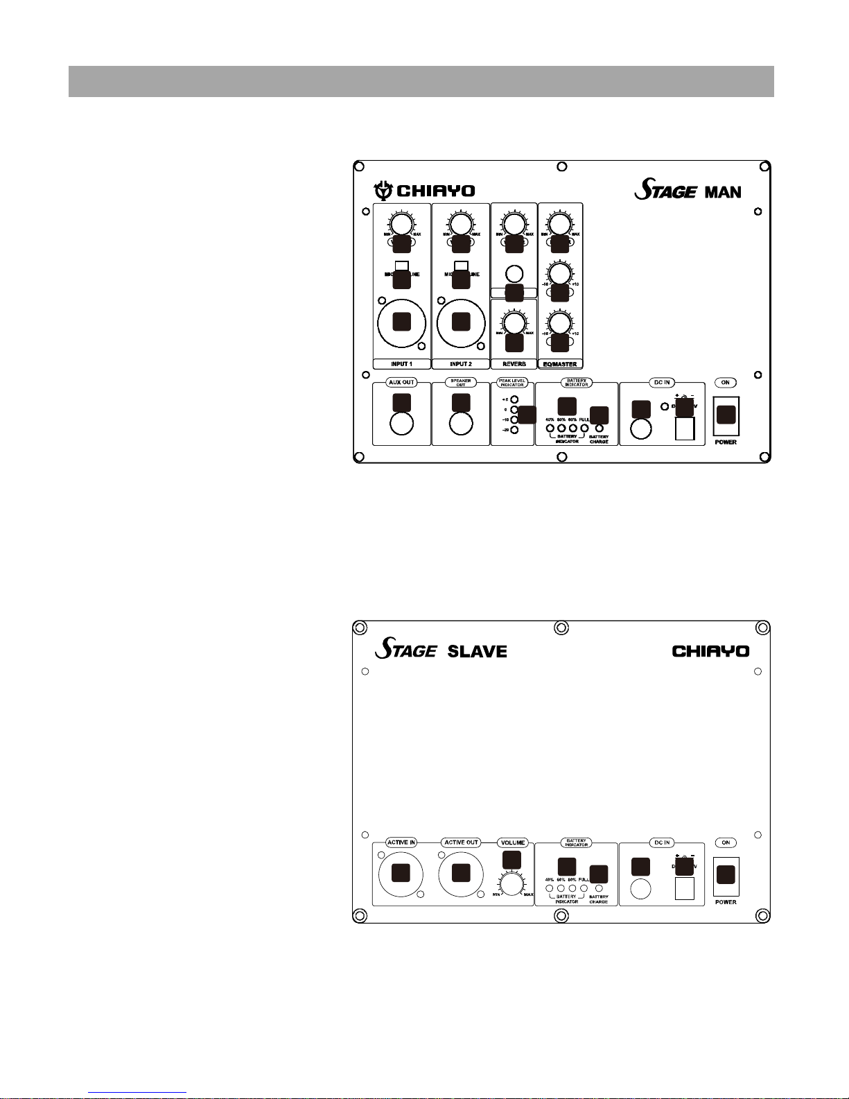
Parts and functions on STAGE MAN control panel
1. Mic/Line #1 volume control
2. Mic/Line level switch #1
3. Min/Line input #1
4. Mic/Line #2 volume control
5. Mic/Line level switch #2
6. Min/Line input #2
7. Line in volume control
8. Line in (3.5mm)
9. Reverb control
10. Master volume control
11. Treble control
12. Bass control
13. Aux output
14. External speaker output
15. Master Limiter indicator
16. Battery indicator
17. Charging indicator
18. Fuse
19. DC in (30-32V/4A)
20. Power on/off
Parts and functions on STAGE SLAVE control panel
1. Audio link input
2. Audio link output
3. Volume control
4. Battery indicator
5. Charging indicator
6. Fuse
7. DC in (30-32V/4A)
8. Power on/off
3 6
13 14
17
1
2
4
5
7
8
10
11
9 12
15
16
18
19
20
1
2
3
4
5
6 7
8
3 6
13 14
17
1
2
4
5
7
8
10
11
9 12
15
16
18
19
20
Page 6
-5-
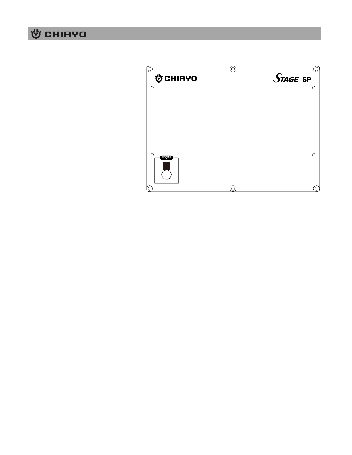
Parts and functions on STAGE SPEAKER control panel
1. Audio input
Starting to operate the STAGE PRO / STAGE MAN
First of all, please charge the system for at least 4~6 hours after unpacking because the built-in
rechargeable battery might have lost some of its charges naturally due to long shipment and
storage time, even though it has been fully charged in the factory before shipment.
To operate this portable sound unit, please switch on the main POWER switch. However, if the
battery indicator stops at 40%, it means that the battery is getting weak and instant charging is
necessary.
The main POWER switch / Volume does NOT automatically switch on the other devices
(modules) since each of them has individual Power/Volume control. To operate those, you
have to switch them on accordingly.
Operating the wired microphone
To use a cable microphone, simply plug it into any MIC IN socket. The combo sockets accept
either XLR or 6.3mm jack. There are individual volume / tone and reverb controls for both
microphones.
Playing the instruments (for STAGE PRO only)
There are 2 inputs for connection with your instrument such as guitar. Above them is the
dedicated volume control.
Music audio inputs
To receive different audio signals from unbalanced sources with different connectors, the unit is
equipped with one 3.5mm and one RCA R/L (STAGE PRO only) jacks. This Line-in area has its
individual volume and tone control (Bass/Middle/Treble), too.
1
Page 7

ISO 9001|ISO 14001|OHSAS 18001
-6-
Digital in (STAGE PRO only)
The Digital-in is for audio connection with the PC/Notebook. Just use a USB cable to connect
the unit and your PC/Notebook to make STAGE PRO the speaker of your device. Its volume is
controlled by the master adjusting knob.
Operating Voice Priority (STAGE PRO only)
Voice Priority operation is only necessary when CD/USB/MP3 is playing.
When the Voice Priority switch is ON, the ducking function will be activated. While the music is
playing, a voice input from either a Wired or Wireless Microphone will temporarily override and
lower the volume of the background music and voice could be heard more clearly.
Background music will return to its original setting when no audio input is entering the
microphone for a certain time. However, if the microphone is not switch off, the reentering of
music into the microphone will also activate the voice priority function.
Operating Loudness (STAGE PRO only)
When the amplifier’s sound is at low level, the tone might not be heard clearly and activating
the Loudness function can raise the tone level to make it clearer.
Limiter Function
There’s an interior anti-overload circuit to protect the amplifier from being damaged due to
over volume output, this design will automatically lower the output when it goes over the limit.
Various audio outputs
Active out: STAGE PRO could be operated as the MASTER unit in an audio link (wired)
configuration. The Master is capable of daisy chain manner wire connecting of up to about 20
active speakers (Stage Slave).
To install the link, connect the output jack of the Master to the Active IN of the 1st
STAGESLAVE. Its Output jack should be connected to the Active-in of the 2nd Stage Slave
and so forth.
Aux out: This 6.3mm jack is used as audio output connection to another active amplifier.
Charging the battery
STAGE PRO/ STAGE MAN uses either two lead-acid batteries or one lithium battery. The
battery power is leveled from 40%, 60%, 80% and FULL. If the LED stays at 40%, the battery
might not be sustainable for long operation. During recharging the indicator LED will flash RED
until the battery power is full, at which the LED changes to GREEN. However, if there is no
battery inside or the battery has problem, the charging LED will stays YELLOW.
Operating the wireless microphone
To operate the wireless system, please switch on the power/volume control on the receiver
module panel and the matching transmitter. Then set the channel on both the transmitter and
receiver module to the same before operation. Please also make sure that master volume
control is set to minimum level before turning on the amplifier, especially working on a wireless
version! Position the Master volume to the middle. Then adjust the receiver volume to a desired
level and the operation is ready.
Page 8
-7-
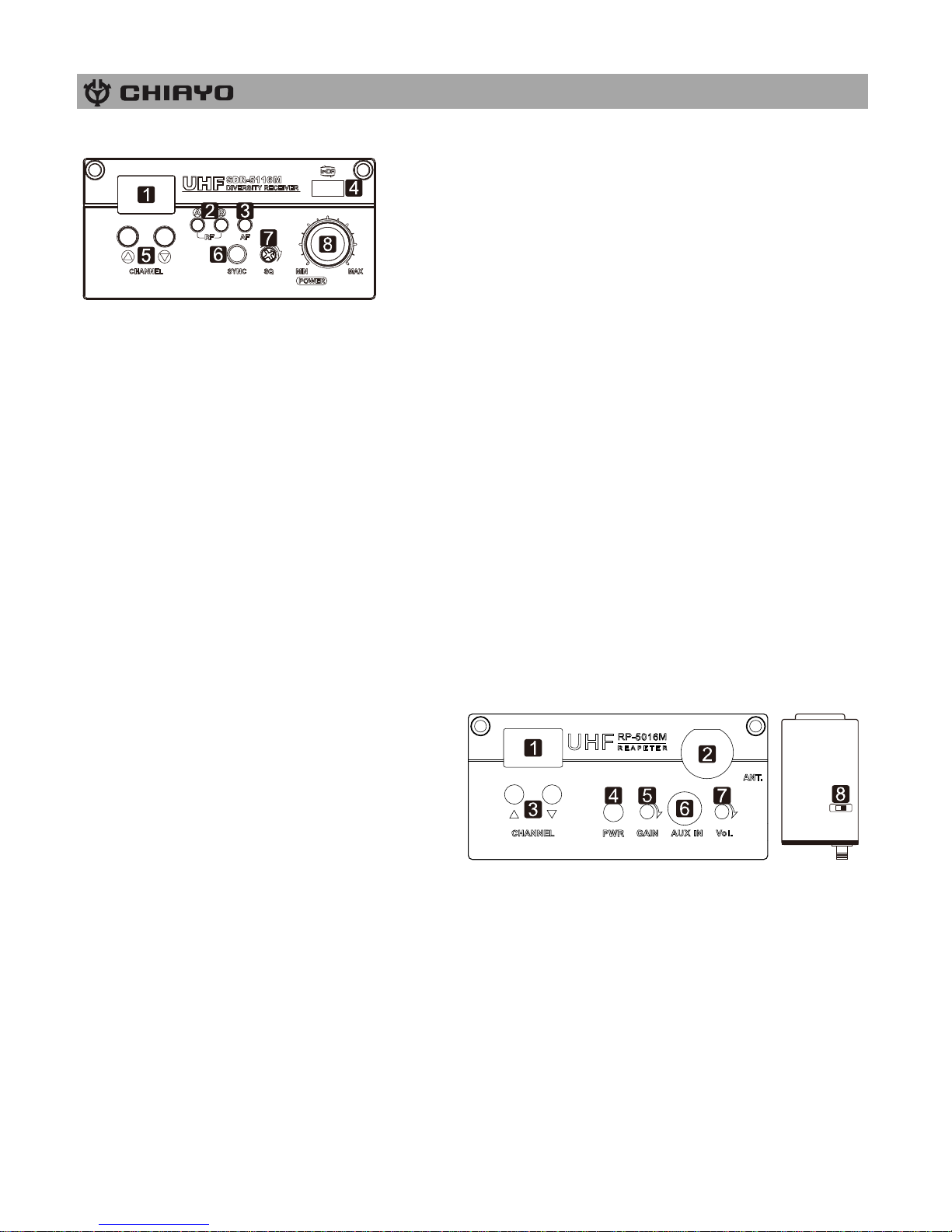
SDR-5200M IrDA|SDR-5100M receiver modules
1. Channel indicator
2. Diversity A/B indicator
3. Audio signal indicator
4. IR sensor area
5. Channel Selector
6. IRDA synchronizing button
7. Squelch control
8. Power switch/volume
control
First turn on the Power of the main unit. Then turn on the individual power of the receiver
module. Select a channel that corresponds to the transmitter. When transmitter is turned on,
either A or B diversity indicator will flash to indicate that signal has been received.
SQUELCH (SQ) setting
When a channel is in use and undesired interference signal is received, turn the SQ in
clockwise direction to make the receiver less sensitive and thus less susceptible to interference.
If this still does not solve the problem, it means this frequency is not applicable at current
position. Please switch over to the next channel.
Channel synchronizing of the receiver and transmitter
1. To achieve a trouble-free synchronization, please limit the distance between the receiver and
transmitter to within 30cm.
2. Align both sensor areas
3. To change the receiver’s channel, please press the synchronizing button of the transmitter.
The transmitter will transmit synchronizing signal to the receiver and change its channel.
4. To change the transmitter’s channel, please press the synchronizing button of the receiver.
The receiver will transmit synchronizing signal to the transmitter and change its channel.
RP-5100M transmitter module
This unit should be installed in the Master
unit as a Repeater Transmitter to perform
wireless link with the Slave unit.
1. Channel indicator
2. Antenna socket(TNC type)
3. Channel selectors: Press ▲(up)▼(down)
to increase/decrease channel number. Please select a non-interfering frequency channel to
those already used in the master unit receiver modules. For wireless link to work, the channel
of the corresponding receiver in the Slave unit should be matched.
4. Power switch.
5. Unit GAIN control: This controls the GAIN level of internal audio output.
6. 3.5mm audio input jack
7. AUX IN GAIN control: This controls the GAIN level of external audio input.
8. Output power setting: LOW (left) for Low output power and HI (right) for high output power.
Low output power will reduce the RF transmission distance and High output power will
extend the possible RF transmission distance. However, if the module is installed on batterypowered amplifiers, HIGH output power would reduce battery operating hour than LOW
output power since it requires more power for stronger RF transmission.
DPRB-600M MP3 recorder player Bluetooth module
HI LOW
Page 9
ISO 9001|ISO 14001|OHSAS 18001
-8-
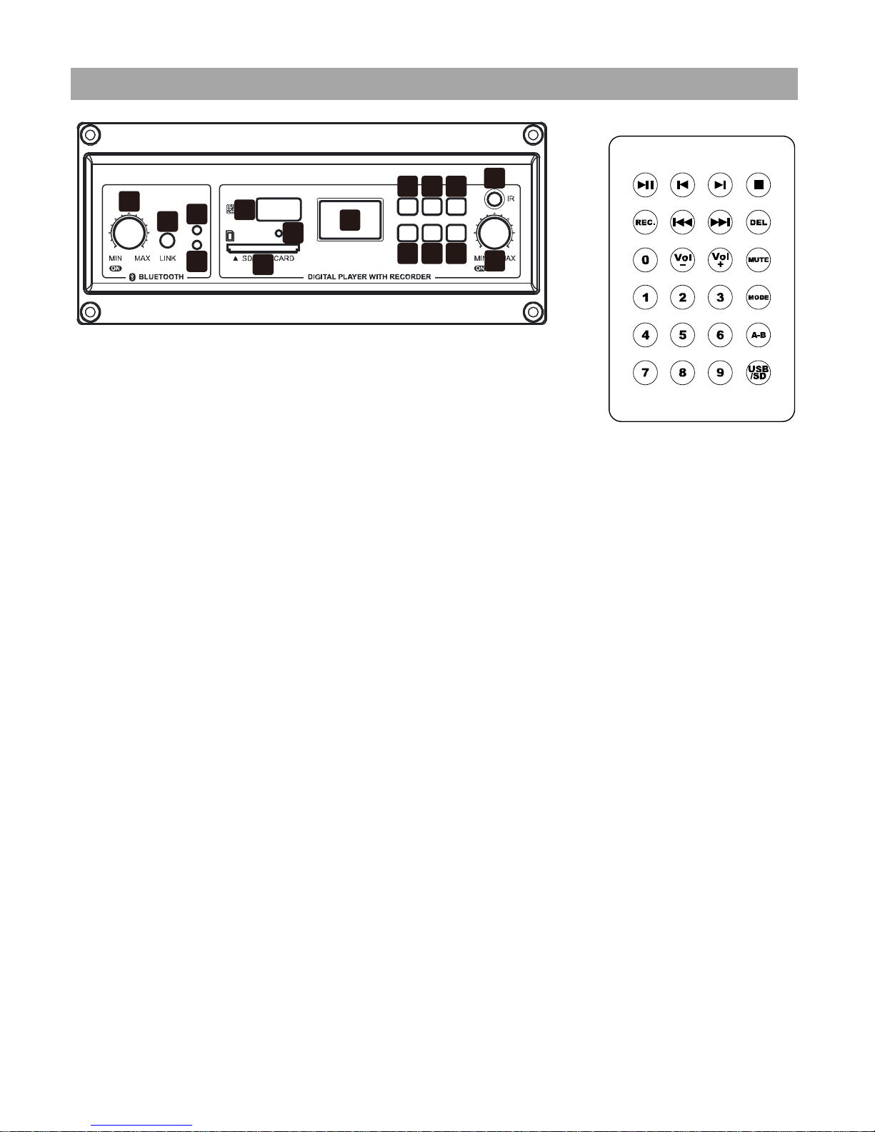
remote control of digital recorder player
Bluetooth receiver section (LEFT)
1. Power/volume control
2. LINK button
3. LOCK LED
4. SCAN LED
Linking instruction
1. Turn on the Bluetooth receiver and both SCAN and LOCK LEDs will flash alternatively.
2. Activate Bluetooth on your device and search new external Bluetooth devices.
3. Find and link to “Bluetooth Speaker” which is listed on your menu.
4. Once the linking is finished, the LOCK LED will flash green.
5. Pressing LINK button can cut the connection.
Digital recorder player section (RIGHT)
1. LCD display
2. Press to return to previous track, press and hold to fast reverse.
3. Press to play/pause or stop recording. (readable formats: mp3, wav and wma)
4. Press to go to next track, press and hold to fast forward.
5. Press to record.
6. Press to switch repeat modes.
7. Press to stop playing or recording.
8. IR sensor area
9. USB input
10. USB/SD indicator: The LED flashes green during playing and red during recording. It lights
red if there is no track to play, lighting green when playing or recording stops.
11. SD card input
12. Power switch/volume control
1
2
3
4
12
1
2 3 4
5 6 7
8
9
10
11
Page 10
-9-
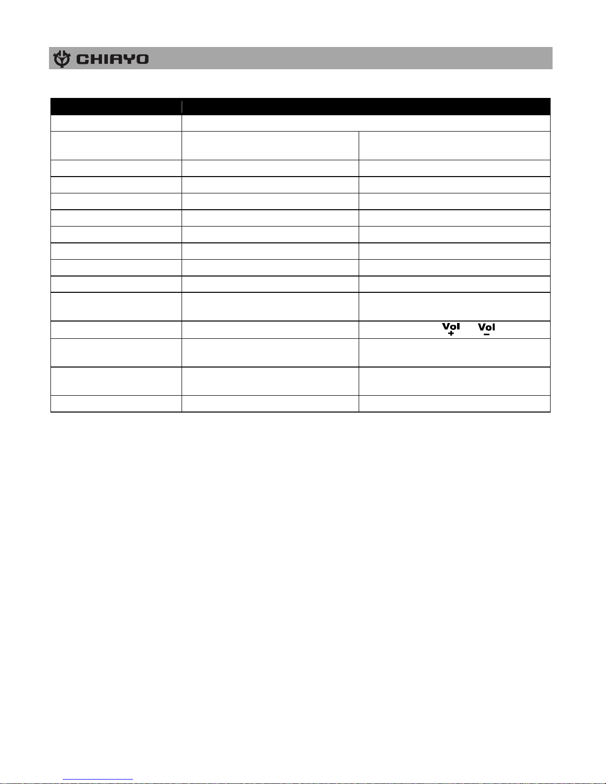
Operating functions on the panel and the remote
Note:
Supports FAT and FAT32 file systems only.
Supports MP3, WAV and WMA music formats only
Record track format :MP3; Bit rate: 128kbps; Sampling frequency: 44kHz
Recordable only when USB/SD is detected.
Record files will be stored in the RECORD folder of USB/SD.
The files will be named as FILE_001, FILE_002, FILE_003…etc.
The name of a deleted track won’t be applied to its next one.
Recordable until FILE_999 appears with LCD displaying Num Full.
LCD displays USB FULL or SD FULL when insufficient memory left.
LCD displays SD LOK if the SD is locked.
Don’t remove the USB/SD during the recording process in case the interrupted track might
be damaged.
Operating function
On the panel
On the remote
Play/pause
Press II
Record
Press ● to record and II or ■ to
stop.
Press REC to record and II or ■ to
stop.
Skip forward
Press I
PressI
Fast forward
Press and hold I
Press and hold I
Skip backward
Press I
Press I
Fast backward
Press and hold I
Press and hold I
Next folder - Press
Previous folder - Press
Track select (button #0-9)
-
input track number, then press II
USB/SD switch
-
Press USB/SD
Repeat mode switch
(ALL/SINGLE/FOLDER)
Press MODE
Press MODE
Volume control
-
Press or
A-B section play
-
Press A-B to start, again to play section
and again to stop
Delete tracks
-
Press DEL to delete track and again to
confirm your delete
Mute
-
press MUTE to mute/recover
Page 11
ISO 9001|ISO 14001|OHSAS 18001
-10-
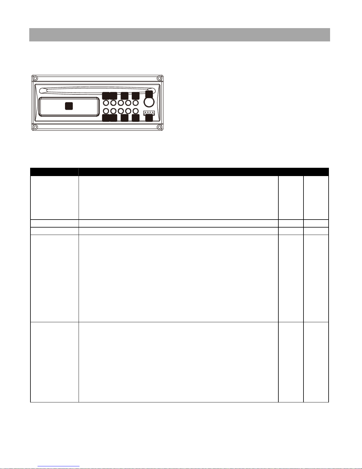
Operating the CD player
Parts and functions
1. LCD display
2. Play/pause
3. Stop
4. Rev-Skip-Cue
5. Eject
6. CD/USB selector
7. Repeat
8. Folder skip
9. Infrared receiving LED
10. USB input
11. Power/volume control
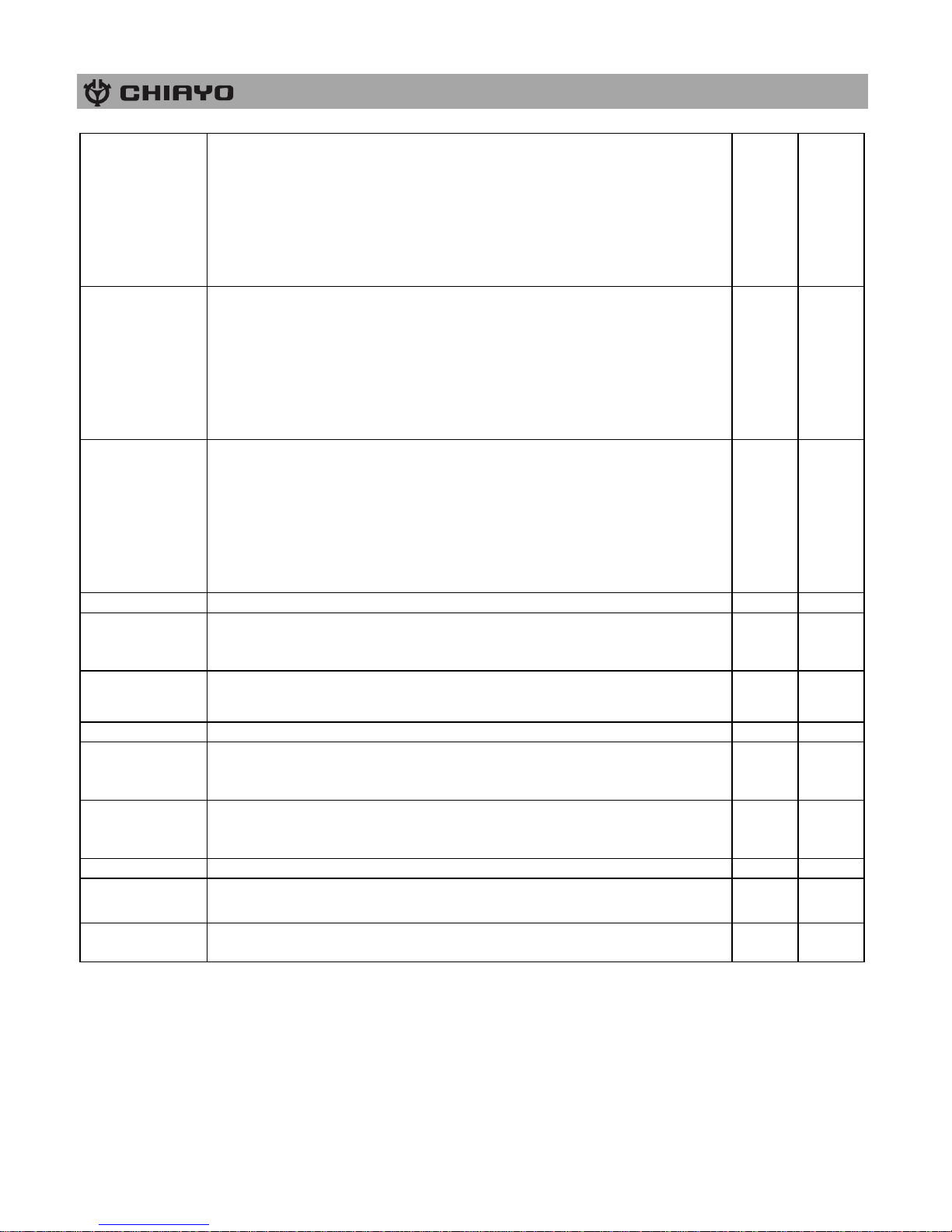
Keys
Functions
Panel
Remote
PLAY/PAUSE
When this key is pushed during CD stop, play will start after track
search.
When this key is pushed during CD is playing, it will be changed to
pause.
When this key is pushed during CD is pausing, it will be changed to
play.
V
V
STOP
When CD is not stop, if this key is pushed then CD will stop.
V
V
FUNC
When press this key will change between CD and USB mode.
V
V
UP/CUE
In stop mode:
Change the starting play track (file) during stop mode, cyclic to the first
track, if it is in the last track.
In program entry mode:
Change to the next track(file) for program select .
In play mode, pause mode, program play mode, random play mode:
Single pressed, skip the playing track (file) to next track (file) for normal
play/pause mode, to next program index track(file) for program
play/pause mode, to next random track(file) for random play /pause
mode.
Continue pressed, fast forward during play/pause when pressed more
than 0.7sec.
V
V
DONW/REV
In stop mode:
Change the starting play track (file) during stop mode, cyclic to the last
track, if it is in the first track.
In program Entry mode:
Change to the previous track (file) for program select.
In play mode, pause mode, program play mode:
Single pressed, skip the playing track (file) to precious track (file) for
normal play/pause mode, to previous program index track (file) for
program play/pause mode.
Continue pressed, fast reverse during play/pause when pressed more
than 0.7sec.
V
V
1
2 3 4 5
6 7 8 9 10
11
Page 12
-11-
FOLDER-UP
In stop mode:
Skip the starting play folder to next folder during stop mode, cyclic to
the first folder if it is in the last folder.
In program entry mode:
Change the file for program select to next folder’s first file, cyclic to the
first folder if it is in the last folder.
In normal play mode:
Skip the playing file to the next folder’s first file.
V
V
FOLDER-DOWN
In stop mode:
Skip the starting play folder to previous folder during stop mode, cyclic
to the last folder if it is in the first folder.
In program entry mode:
Change the file for program select to previous folder’s first file, cyclic to
the last folder if it is in the first folder.
In normal play mode:
Skip the playing file to the previous folder’s first file.
V
V
REPEAT
In mp3 mode and in USB mode .
If this key is pushed, PLAY mode is changed cyclically shown below.
PLAY ALL RANDOM→REPEAT TRACK→REPEAT
FOLDER→REPEAT ALL→RANDOM REPEAT→PLAY ALL
IN CD mode If this key is pushed, PLAY mode is changed cyclically
shown below.
PLAY ALL RANDOM→REPEAT TRACK→REPEAT ALL→RANDOM
REPEAT→PLAY ALL.
V
EJECT
When this key is pushed, door is moved out.
V
V
PROG
Set to programming mode.
When programming mode, “stop” key is pushed then program is all
cleared.
V
MUTE
When this key is pushed during CD is playing, the set will mute the
output. Pushing again can recovery the output.
V
POWER
Power SW of the set.
V
V
ESP
In CDDA mode, Press ”ESP” key, The ESP display lighted and the set
is in electronic anti-shock state. The electronic anti-shock time is about
40 seconds. Press “ESP” key again, cancel the ESP function.
V
ID3
When this key is pressed , the“ID3”in the LCD display will flash, and the
ID3 TAG is displayed pressing this key again will cancel the ID3
function
V
0~10
You can use these keys to select the track you want directly.
V
VOL.-
When this key is pushed, the volume will decrease by 1dB per step, the
min. volume is 0dB.
V
V
VOL.+
When this key is pushed, the volume will increase by 1dB per step, the
max. volume is 30dB.
V
V
Caution: This player does not accept 8-cm diameter CD. User is advised to have the USB 2.0
formatted in “FAT” or “FAT 32”. The built-in USB 2.0 player can not be able to read the MP3
files stored in your USB if it is not formatted by either “FAT” or “FAT-32”. To avoid damage to
the USB, remember to detach it only after switching off the player.
Page 13
ISO 9001|ISO 14001|OHSAS 18001
-12-
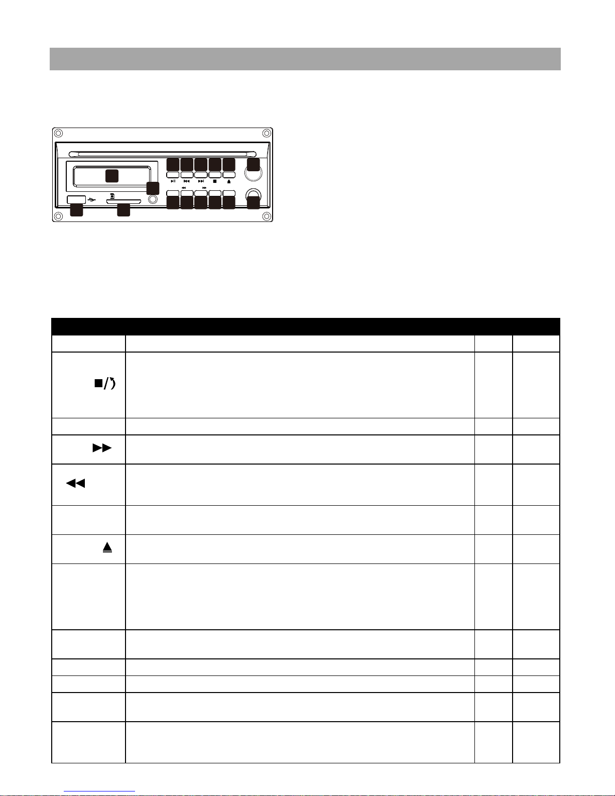
Operating the DVD player
Parts and functions
1. Power/volume control
2. Eject
3. Stop
4. Skip/forward
5. Skip/reverse
6. Play/pause
7. Video output
8. N/P
9. Repeat
10. Cue
11. Rev
12. Function switch
13. LCD display
14. IR LED
15. SD card input
16. USB 2.0 input
Keys
Finction
Panel
Remote
PLAY/PAUSE
Press this key to change between PLAY and PAUSE modes.
V
V
STOP
When this key is pressed during playing, the set is changed to stop.
The stop point is memorized. Then pressing PLAY/PAUSE key, the set
will play from the stop point. When this key is pressed twice during
playing. The set is changed to stop, then pressing PLAY/PAUSE key, the
set will play from the beginning.
V
V
FUNC
When this key is pressed, mode is changed between USB and disk.
V
V
CUE
In play state, press “CUE” to do fast play. Each press of the key can
change the play speed to X2, X4, X8, X20 and normal in sequence.
V
REV
In play state, press this key to carry out the fast backward play. Every
press the key, the backward play speed will change for one
time.X2,x4,X8,X20 and normal in sequence.
V
N/P
Press the key to change the TV system in the following sequence:
PAL→AUTO→NTSC→PAL→...
V
V
EJECT
Press this key, the disk will move out.
If the disk is not taken away, press this key again, the disk will slot in.
V
REPEAT
The default is REPEAT ALL
IN MP3 WMA state ,the repeat sequence is as following:
REPEAT 1→REPEAT DIR→REPAT ALL→REPEAT 1→...
In CD playing state , the repeat sequence is as following:
REPEAT 1→REPAT ALL→REPEAT 1→...
V
V
MUTE
When this key is pressed during disc is playing, the set will mute the
audio output. Press again to recover the output.
V
POWER
Power switch of the set.
V V GOTO
Press GOTO to reach the title, chapter or time you want.
V
OSD
In play state, press OSD key, the play information of the disc will show
on the screen. Press it again, the OSD information will disappear.
V
PROG
After programming, the player will play the title, chapter or songs follow
the programmed order.
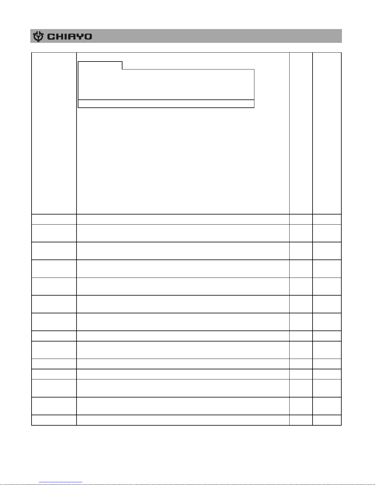
Press PROG button ,the menu will display on the screen as following:
V
SD/M MC C ARD
POWER / VOL
VIDEO
PLAY
PAUSE
FUN C REP EAT N/P
STOP EJEC TREV- SKIP- CUE
REV CUE
123456
789101112
13
14
1516
Page 14
-13-
PROGRAM
1--:--
5--:--
9--:--
13--:--
2--:--
6--:--
10--:--
14--:--
3--:--
7--:--
11--:--
15--:--
4--:--
8--:--
12--:--
16--:--
play
clear
In the picture T means TITLE, C means CHAPTER. The divided unit of
DVD disc is title, and can divide the title for several chapters.
Usually one movie has one title.
Some disc are not divided in this way, please pay attention to it when
operate GOTO” and “PROG” function.
Input relevant title, chapter that you want with the arrows and number
keys.
Use ↑↓←→ to move the cursor to “PLAY” in the picture above, then
press “ENTER” button .the player will start playing follow the
programmed order.
Also use the same way to move the cursor to “CLEAR” and press
“ENTER” button can clean the programmed order.
Press “PROG” key again will exit the program mode.
PBC
The key only act for VCD disc.
V
AUDIO
In play state, press “AUDIO” key can choose different audio channels
in the DVD disc.
V
ZOOM
In play state, press “ZOOM” key ,the display screen will zoom by
2X, 3X, 4X, 1/2X, 1/3X, 1/4X and normal play.
V
SLOW
Press “SLOW” key ,the set will become slow motion as following cycle:
SF ½→SF 1/3→SF 1/4→SF 1/5→SF 1/6→SF 1/7→normal→SF ½→...
V
↑↓←→
ENTER
Cursor move keys and confirm keys.
V
REV-SKIP-
CUE
Press one of these keys to skip to the next track, long press one of these
keys will search forward or backward.
V V ANGLE
Press “ANGLE” to choose different angles of the disc that recorded with
multi-angle. It doesn’t work if the DVD disc doesn’t support multi-angle.
V
RANDOM
When this key is pressed, it will become random play mode.
V
SUB-T
In play state press “SUB-T” button to choose the different subtitles in the
DVD disc.
V
SETUP
Press “SETUP” key to enter setup manual.
V TITLE
Press “TITLE” key the screen will show title and manual for selection.
V
VOL.-
When this key is pressed, the volume will decrease by 1dB per step, the
minimum volume is 0dB.
V
VOL.+
When this key is pressed, the volume will increase by 1dB per step, the
maximum volume is 40dB.
V
0~9;10+
You can use these keys to select the track you want directly.
V
Page 15
ISO 9001|ISO 14001|OHSAS 18001
-14-
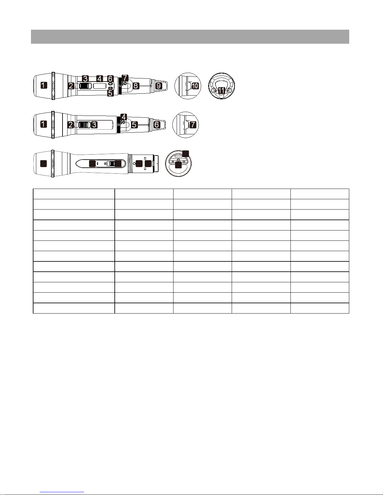
UHF handheld transmitters(SQ-6100 IrDA(R)|SQ-6100 IrDA|SQ-2100 IrDA|SQ-1100 IrDA)
→SQ-6100 IrDA(R)|SQ-6100 IrDA
→SQ-2100 IrDA
→SQ-1100 IrDA
Parts and functions
SQ-6100 IrDA(R)
SQ-6100 IrDA
SQ-2100 IrDA
SQ-1100 IrDA
Cartridge 1 1 1 1
Battery power LED
2 2 2
2
Power switch
3 3 3
3
LCD 4 4 - -
Menu button
5 5 -
-
Setting button
6 6 -
-
IrDA synchronizing button
7 7 4
4
Battery compartment
8 8 5
5
Color cap 9 9 6 -
IrDA sensor area
10
10 7 6
Charging port
11 - -
7
Battery installation & indicator
This transmitter requires 2 x AA batteries to operate.
To install, remove the battery cover and slide the batteries into the battery compartment &
replace the battery cover.
Note: Batteries contain a corrosive acid that may leak and damage the transmitter when stored
for a long period. Batteries should be removed from the transmitter before storing without use
for more than 4 weeks.
When the transmitter is switched ON, a red LED will blink once to indicate the batteries
installed are in good condition. If the LED remains illuminated, it means the batteries are
weak and require replacement.
1 2 3
7
4 5
6
Page 16
-15-
Channel synchronizing of the receiver and transmitter
1. To achieve a trouble-free synchronization, please limit the distance between the receiver and
transmitter to within 30cm.
2. Align both sensor areas
3. To change the receiver’s channel, please press the synchronizing button of the transmitter.
The transmitter will transmit synchronizing signal to the receiver and change its channel.
4. To change the transmitter’s channel, please press the synchronizing button of the receiver.
The receiver will transmit synchronizing signal to the transmitter and change its channel.
Other settings(SQ-6100 IrDA(R)|SQ-6100 IrDA)
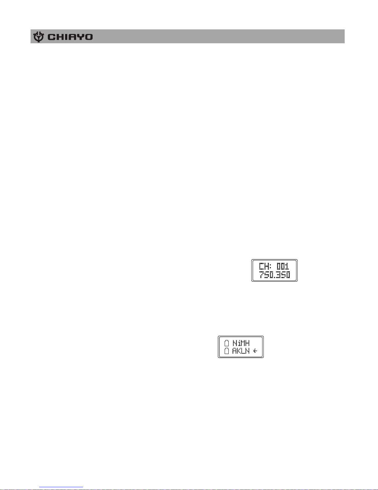
1. Channel setting
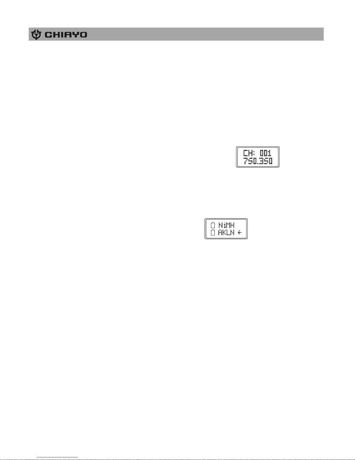
Use MENU button to go to the CHANNEL|FREQUENCY page.︰
After pressing the SET button for 3 seconds, the cursor will flash to allow changes to be made.
Pressing SET / MENU buttons will increase / decrease the channel number. The corresponding
frequency will change accordingly. 3 seconds after selecting a channel, it will be automatically
saved.
2. Battery type setting
Use MENU button to go to the BATTERY TYPE page.︰
After pressing the SET button for 3 seconds, the cursor will flash to allow changes to be made.
Press SET button to select either NiMH (rechargeable battery) or AKLN (alkaline battery). 3
seconds after selecting a battery type, it will be automatically saved.
Remark: NiMH battery must be selected when rechargeable battery is being used. Never
select AKLN (alkaline) when transmitter is intended for charging as alkaline battery isn’t
rechargeable. Wrong battery selection will result in battery sensing electronics to display wrong
and misleading status information.
Page 17
ISO 9001|ISO 14001|OHSAS 18001
-16-
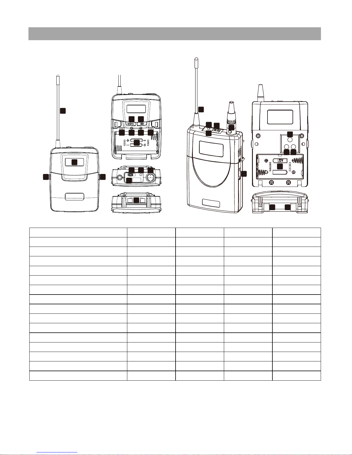
UHF belt-pack transmitters(SM-7100 IrDA|SM-6100 IrDA|SM-2100 IrDA|SM-1100 IrDA)
SM-7100 IrDA|SM-6100 IrDA|SM-2100 IrDA
SM-1100 IrDA
Parts and functions
SM-7100 IrDA
SM-6100 IrDA
SM-2100 IrDA
SM-1100 IrDA
Antenna 1 1 1 1
LCD 2 2 - -
Cover release button
3 3 3
6
Power switch
4
11
11
3
IrDA synchronizing button
5 5 5
7
Menu button
6 6 6
-
Setting button
7 7 7
-
High-impedance gain control (GT)
8 8 8
8
Low-impedance gain control (MT)
9 9 9
9
Battery compartment
10
10
10
10
Audio mute switch
11 - -
-
Battery power LED
12
12
12
2
IrDA sensor area
13
13
13
4
Mini XLR connector
14
14
14
5
Charging contacts
15
15
15
11
Battery installation & indicator
This belt-pack requires 2 x AA batteries to operate.
To install, open the battery cover using the cover release buttons and insert the batteries into
the battery compartment.
1
2
3 3
9
7
84 5
6
10
11 121314
15
1
2
3
4
5
6
7
8
10
11 11
9
Page 18
-17-
Note: Batteries contain a corrosive acid that may leak and damage the belt-pack when stored
for a long period. Batteries should be removed from the belt-pack before storing without use for
more than 4 weeks.
When the transmitter is switched ON, the battery power LED (red) will blink once to indicate the
batteries installed are in good condition. If the LED remains illuminated the batteries have
expired and require replacement.
Channel synchronizing of the receiver and transmitter
1. To achieve a trouble-free synchronization, please limit the distance between the receiver and
transmitter to within 30cm.
2. Align both sensor areas
3. To change the receiver’s channel, please press the synchronizing button of the transmitter.
The transmitter will transmit synchronizing signal to the receiver and change its channel.
4. To change the transmitter’s channel, please press the synchronizing button of the receiver.
The receiver will transmit synchronizing signal to the transmitter and change its channel.
GAIN setting (GT|MT)
Gain control enables the user to set different output levels. GT is for the use of instrument with
high impedance, such as guitar while MT is for the use of low impedance such as lapel or
headset microphones.
Other settings(SM-7100 IrDA|SM-6100 IrDA)
1. Channel setting
Use MENU button to go to the CHANNEL|FREQUENCY page.︰
After pressing the SET button for 3 seconds, the cursor will flash to allow changes to be made.
Pressing SET / MENU buttons will increase / decrease the channel number. The corresponding
frequency will change accordingly. 3 seconds after selecting a channel, it will be automatically
saved.
2. Battery type setting
Use MENU button to go to the BATTERY TYPE page.︰
After pressing the SET button for 3 seconds, the cursor will flash to allow changes to be made.
Press SET button to select either NiMH (rechargeable battery) or AKLN (alkaline battery). 3
seconds after selecting a battery type, it will be automatically saved.
Remark: NiMH battery must be selected when rechargeable battery is being used. Never
select AKLN (alkaline) when transmitter is intended for charging as alkaline battery isn’t
rechargeable. Wrong battery selection will result in battery sensing electronics to display wrong
and misleading status information.
Page 19

ISO 9001|ISO 14001|OHSAS 18001
-18-
Maintenance-free Lead Acid battery
Guidelines for maintenance-free Batteries:
1. Battery should operate at temperatures between 15°C ~ 50°C. To ensure a longer life span, it
should be kept between 5°C ~ 35°C. For optimum result, 20°C ~ 25°C will be ideal. When
temperature falls 15 degrees below zero, battery will undergo some changes in its chemical
contents and therefore cannot be recharged. Operating the battery at higher temperature will result
in higher capacity but shorter lifespan, whereas lower temperatures operation has a longer lifespan
but less capacity.
2. If the battery is not recharged 72 hrs after it is completely used, it will be permanently
damaged.
3. When the battery is being charged, the internal gases will be electrolyzed into water at the
negative charge, maintaining the battery’s storage abilities with no water added. However, erosion
at the charged ends of the battery will cause poor performance.
4. The battery’s cycle lifespan (no. of charge and discharge cycle) is determined by the degree at
which power is dissipated, especially the degree of discharged each time it is used and the
recovery charging method. For normal use, the battery can be used for longer hours when less
power is dissipated each time and vice versa. At 25°C, maintenance-free batteries could be
charged 150 ~ 200 times at 100% discharge each time.
5. Decrease in capacity, internal short circuit, deformation in appearance, erosion of charged ends
and decrease in open circuit voltage are symbols indicating battery is approaching the end of its
life cycle.
6. When two batteries are used in parallel connection, the resistance of the cables should be kept
equal.
Properties of the Lead Acid Battery:
1. Has no memory effect. Can be charged anytime, even when the recharge indication light is off.
2. Performance and efficiency are affected by changes in the environment, especially temperature
and humidity. (Best operated between 20°C ~ 25°C)
3. Battery discharge naturally according to a certain pattern even not in use. For best performance
and a prolonged lifespan, it should be recharged every month even when not in use.
4. Under normal circumstances, battery could last for about a year.
5. When the battery’s life expires, possible indicators include internal short-circuit, decrease in
capacity, deformation in appearance, erosion of charged ends and decrease in operating voltage.
User’s Precautions:
1. For first-time use, charge the battery for 10 hrs until it is fully charged.
2. To maintain performance and lifespan, if product has not been used for 3 months after the initial
shipment, please fully charge the battery.
3. Before each use, it’s advisable to charge the battery to its full capacity.
4. The average lifespan of the battery is one year. The user is advised to change the battery after
one year of use.
5. The current consumption is in direct ratio with load current. The more current consumption, the
less the operation time.
6. Warranty will be void if the battery is not charged for a prolong period as it may lose all its
charge and could never be recovered again.
Page 20

CHIAYO ELECTRONICS CO.,LTD.
Http://www.chiayo.com.tw|Email: [email protected]
Office: 30, Lane 27, Section 4, Jen-Ai Road, Taipei 10685, Taiwan|Tel: 886-2-27415741|Fax: 886-2-27525242
Factory: 88, Chung-Hsiao Street 2, Chiayi 60080, Taiwan|Tel: 886-5-2711000|Fax: 886-5-5767611
 Loading...