

CHIAYO SDR-1900 User Manual
SDR-1900 IrDA
UHF 2-Way Synchronizing Diversity Wireless Microphone System
ISO 9001
ISO 14001
OHSAS 18001
GREEN PRODUCT
Operation Manual
IS O
14 0 0 1
RE GIST ERE D
O H SAS
18 0 0 1
RE GIST ERE D
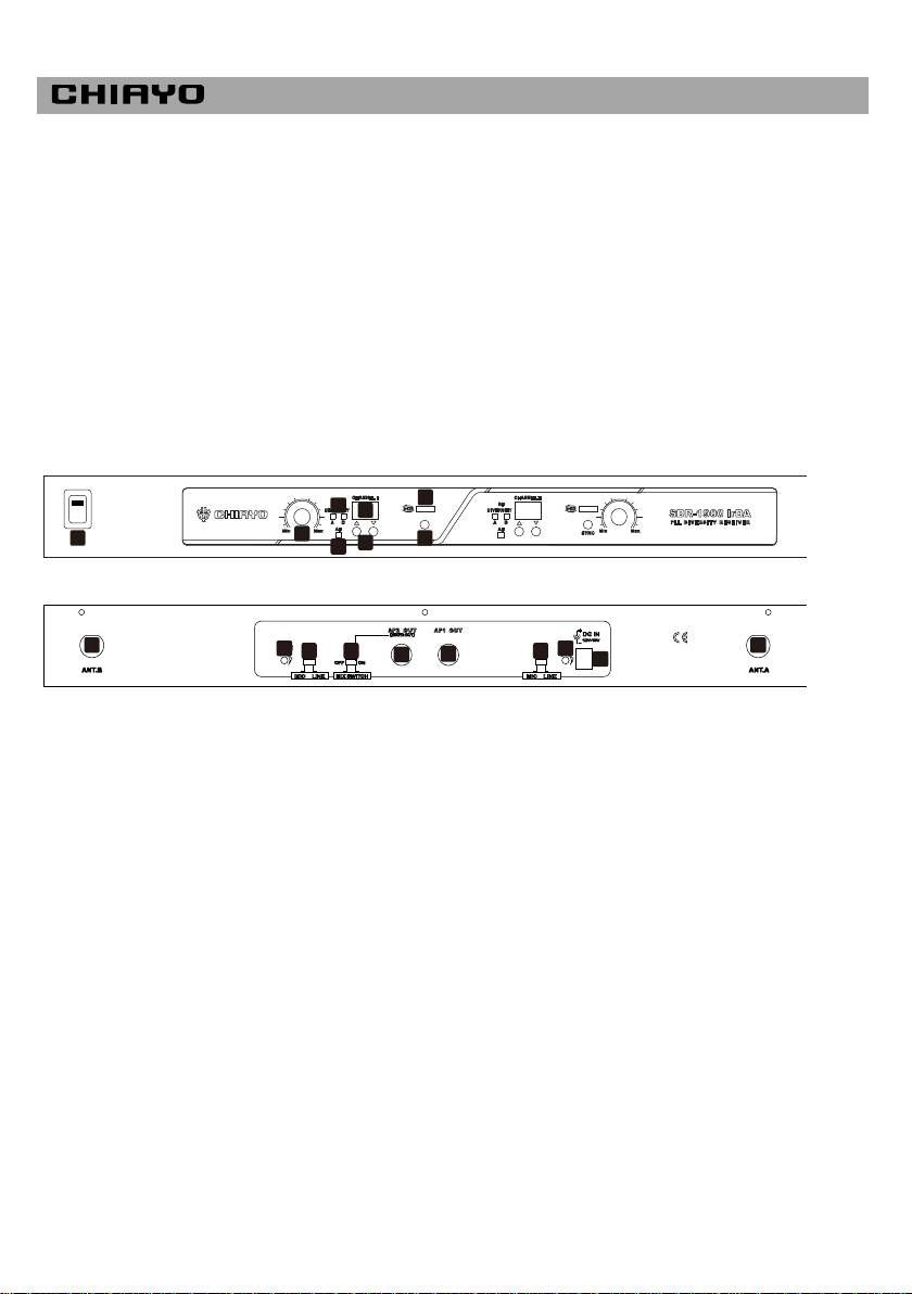
1. Power switch
2. Volume control
3. RF diversity A B indicator
4. AF indicator
5. 7-segment channel display
6. Channel selector
7. IrDA synchronizing area
8. IrDA synchronizing button
9. Antenna B (TNC socket)
10. CH2 squelch control. Clockwise to increase level.
11. Mic /Line level switch (CH2)
12. Mix output on/off switch
13. CH2 unbalanced audio output (mixed)
14. CH1 unbalanced audio output
15. Mic /Line level switch (CH1)
16. CH1 squelch control. Clockwise to increase level.
17. DC input
18. Antenna A (TNC socket)
1
2
3
4
5
6
7
8
9
10
11 12
13
14
15
16
17
18
Thank you for choosing this wireless microphone system!
Our products are designed to last and for user friendly operation. Each system consists of:
1. a receiver
2. two handheld/beltpack transmitters
3. a pair of antennas
4. a switching adaptor
5. an operation manual
For more details, please take a few moments to read this operating manual to have a thorough
understanding of the function and operation of both transmitter and receiver.
Parts and functions of SDR-1900 IrDA receiver
Front panel
Rear panel
-1-
ISO 9001|ISO 14001|OHSAS 18001
Making changes to various settings on SDR-1900 IrDA receiver
1. Changing CHANNEL / FREQUENCY
This can only be done by pressing UP or DOWN buttons. After a new channel is selected, it will
be automatically saved and stored into the memory.
2. CHANNEL scanning
For an interference- free operation, we may need a cleaner channel if the current one receives
too much interference. To perform the scan function, the transmitter must be switched off. After
a channel button (▲or▼) is hold pressed for 3 seconds, the receiver will do an auto channel
scan UPwards/DOWNwards until it stops at the next cleaner one. Then change the
transmitter’s channel accordingly.
3. Channel synchronizing of the receiver and transmitter
a. To achieve a trouble-free synchronization, please limit the distance between the receiver and
transmitter to within 30cm.
b. Align both sensor areas
c. To change the receiver’s channel, please press the synchronizing button of the transmitter.
The transmitter will transmit synchronizing signal to the receiver and change its channel.
d. To change the transmitter’s channel, please press the synchronizing button of the receiver.
The receiver will transmit synchronizing signal to the transmitter and change its channel.
4. Adjusting VOLUME level
Volume level can be adjusted by rotating the designated volume knob. Clockwise to increase
the volume and counterclockwise to decrease the volume.
5. Adjusting SQUELCH level
The squelch control is on the back of the receiver. When strong interference happens to the
operation, you can use a small screw driver to increase the squelch level by turning the
switcher clockwise. If the interference is too strong even the level is already set to maximum,
the currently in-use channel is not applicable in this location and a change to channel is
recommended.
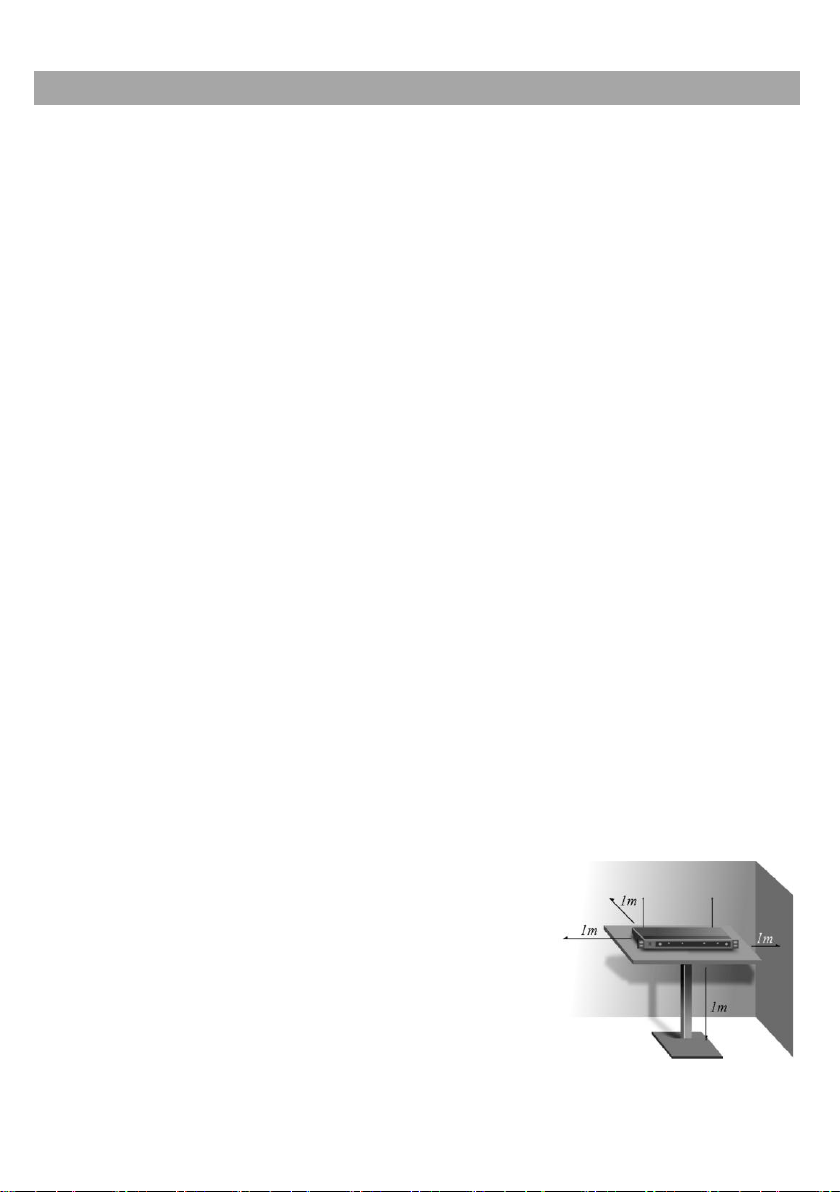
Receiver installation
For best operation, the receiver should be at least 1m above
the ground and 1m away from a wall or metal surface to
minimize reflections. The transmitter should also be at least
1m away from a wall or metal surface to minimize reflections.
The transmitter should also be at least 1m away from the
receiver. Keep antennas away from noise source such as
motors, automobiles, neon light as well as large metal objects.
-2-
 Loading...