

Chevrolet R-V 1989, P 1989 Wiring Diagrams

1989
WIRING DIAGRAMS
R-V, P TRUCK
MODELS
When reference is made in this manual to a brand name, number, or specific tool, an equivalent product may
be used in place of the recommended item
All information, illustrations, and specifications contained in this manual are based on the latest product
information available at the time of publication approval. The right is reserved to make changes at any time
without notice.
No part of this publication may be reproduced, stored in any retrieval system or transmitted, in any form or by
any means, including but not limited to electronic, mechanical, photocopying, recording or otherwise, without the
prior written permission of the GMC Truck Division of General Motors Corp. This includes all text, illustrations,
tables and charts.
X-8940
©1988 General Motors Corporation August, 1988
AH rights reserved Printed in U.S.A.
WIRING DIAGRAMS 2
WIRING DIAGRAMS
DESCRIPTION
All diagrams in this manual are based on the latest product information at the time of publication approval. The right is
reserved to make changes at any time without notice.
SUBJECT PAGE
Description 2
Tracing Circuits 2
Baste Electric Circuits 2
Circuit Diagnosis 8
Abbreviation List 7
Diagnostic Tools 11
Wire Size Conversion Table 11
On-Vehicle Service 11
Circuit Maintenance and Repair 11
Weather Pack Connectors 12
Metri-Pack Connectors 12
Wiring Repair 14
Special Tools 15
VEHICLE SECTION
R/V Models A-1
P :Chassis B-1
• The diagrams are to be traced from the source of
electricity (the battery positive post) to ground. The
ground may be a chassis ground on a certain component (such as an alternator or a starter), or a wire
from a component to a chassis or frame ground
(such as used on the electronic control module and
instrument panei). All grounds are connected to the
negative battery post through body and/or angina
ground wires and straps.
• Many times the source of the electricity is shown as
the ignition switch or the fuse block. This is done to
eliminate the confusion that would occur if the entire
power distribution was shown in each circuit. For a
detailed outline of the power to the ignition switch or
the fuse block, refer to the power distribution circuit.
• The ground portion of the circuit (usually circuit 150
or 151) may be shown entirely, or it may refer to the
ground distribution circuit in order to avoid confu-
sion of listing ail the grounds in one splice on a sin-
gle page.
• For ease of diagnosis, ali splices and grounds are
identified by number, and all the wires on a common
splice or ground are identified by circuit number,
size (in mm) and color. Each component or circuit
common to s spliced wire is called out by the page
number of that circuit. This will help identify and di-
agnose multiple electrical problems that could occur
in a truck.
• All connectors are shown with their part numbers to
save time when ordering these parts.
• Switches are shown in their at rest positions, unless
otherwise marked.
TRACING CIRCUITS
Figures 1 through 3 are examples of how the wiring
diagrams are laid out., and will be referred to, throughout
this description.
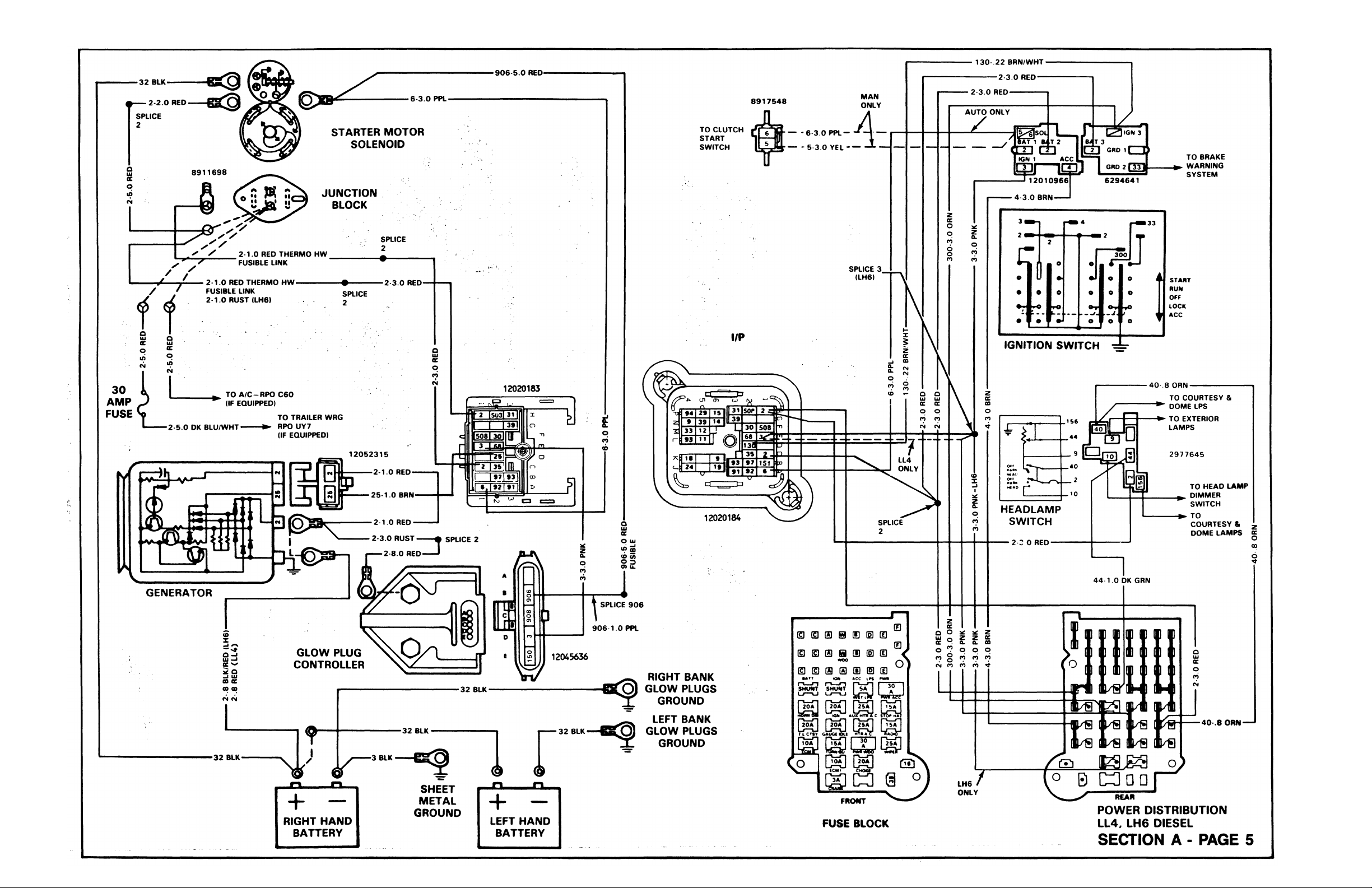
In order to trace a circuit on these diagrams, start from
the source, the battery. In figure 2, the battery positive
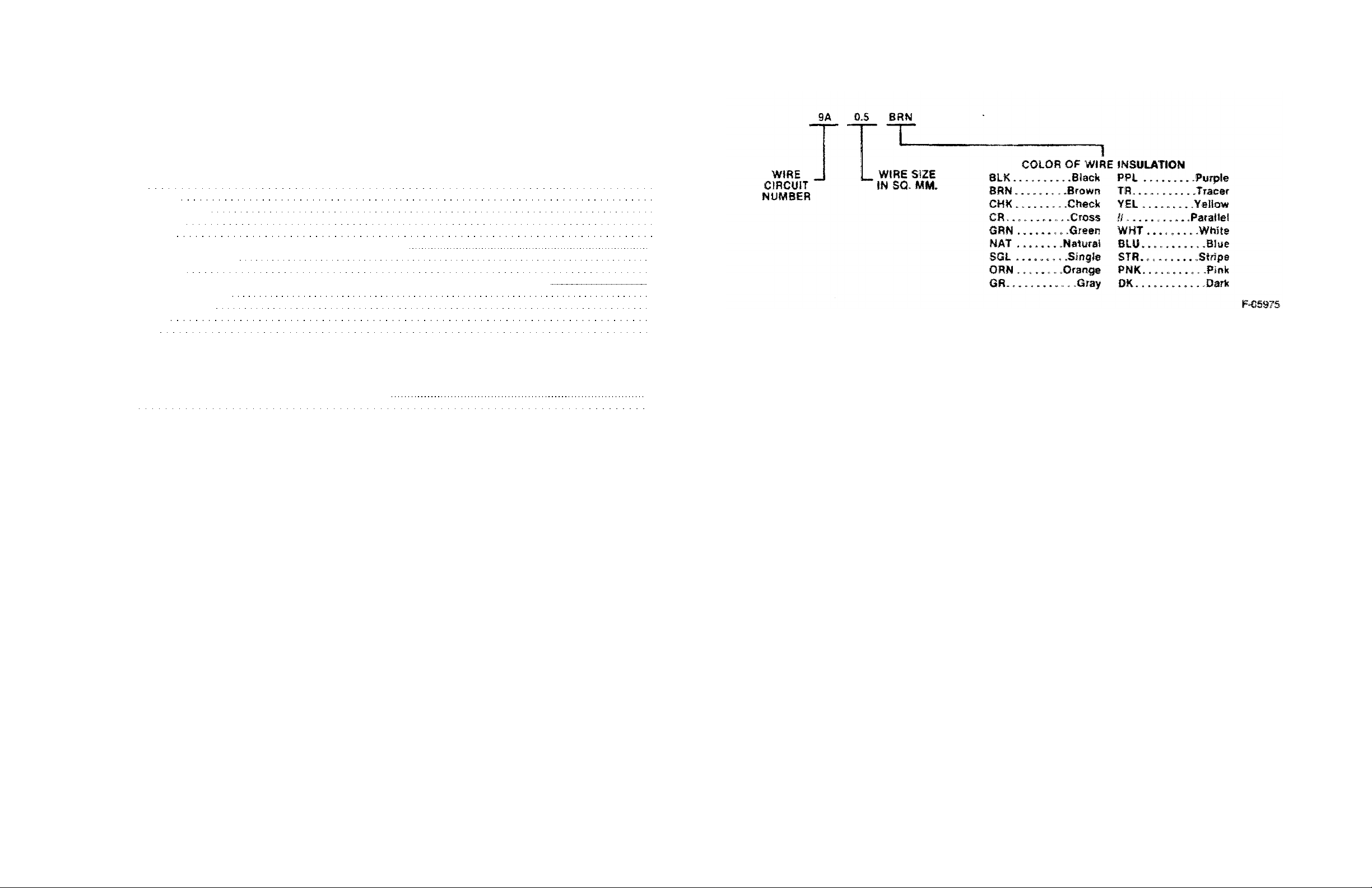
Figure 1—Wire Coding
circuit is a 19.0 mm black wire. This wire runs from the
battery to the starter motor, and supplies power to the
starter motor post.
Once you have determined the source of power to your
component, from the Power Distribution Circuit (figure 2),
then refer to the individual circuit you are working on for
more detail about that circuit. (Figure 3 shows the starting
circuit).
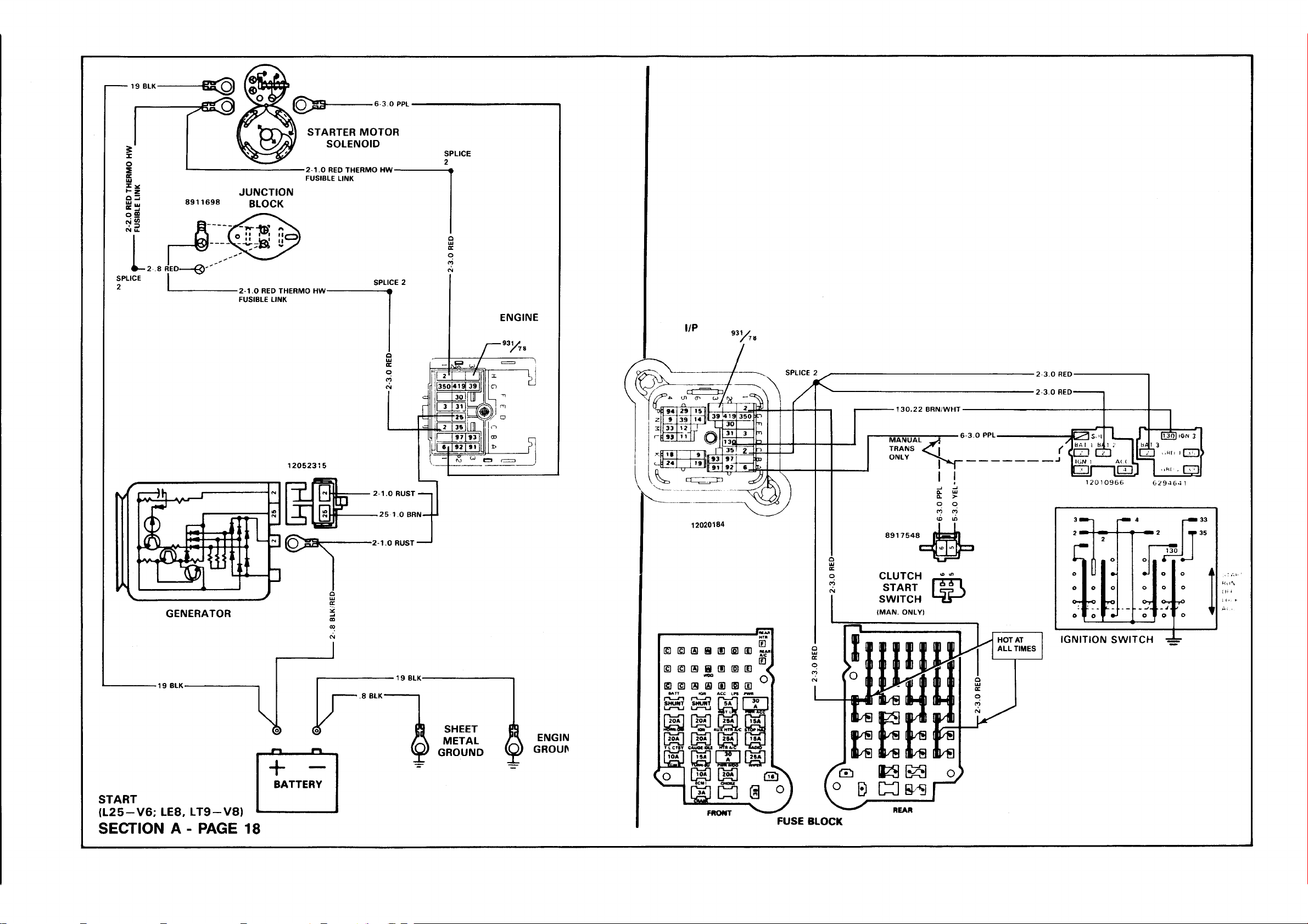
In figure 3, the starter motor circuit is shown. This circuit
shows the battery feed coming from the Power
Distribution page. The cable comes from the battery to
the start©? positive post. At the starter post, other circuits
such as the generator, ignition switch, and electronic
control module are fed.
When the ignition switch is in the start position, power
flows from circuit #2 through the switch, to circuit #6.
Circuit #6 goes through the clutch switch with an
automatic transmission. At the clutch switch the circuit is
opened, unless the dutch is depressed.
At the solenoid the current flowing from circuit #6
closes the soiertoid, allowing current to flow from the
battery at circuit #1 to the starter motor. The current
flowing to the starter motor, causes the starter motor to
spin.
BASIC ELECTRICAL CIRCUITS
An electrical circuit starts from a supply of electricity
back to a load and then conducts the electricity back to
the supply of electricity. There should be a device to open
and close the circuit, and a protective device to open the
circuit in case too much current is drawn into the circuit by
an overload condition. Electrical circuits can be set up as
series circuits, parallel circuits or series/parallel' circuits.
The circuits in trucks are usually parallel circuits.
WIRING DIAGRAMS 5
WIRING DIAGRAMS 6
path. For example the switch controlling the headlights is
at the power end of the circuit while the door switch
controlling the domelight completes the ground path.
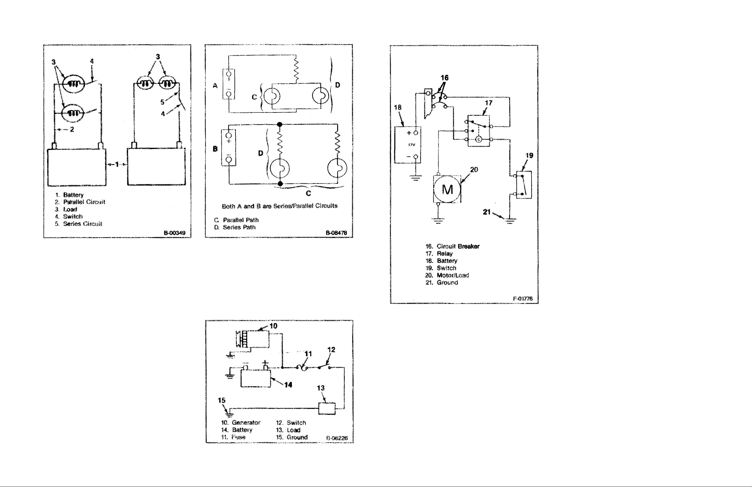
Relays are remotely controlled switches. They are used
in high current circuits and in circuits controlled by
sensors.
Relays are designed so that a small current circuit wi!3
he able to control a large current circuit.
CIRCUIT BREAKERS (Figure 7)
Circuit breakers are another form of circuit protector.
There are two types of circuit breakers; automatic reset
and remote reset.
The automatic reset breaker opens when excess
current heats a bimetallic strip, causing the strip to bend
and open a set of contacts. Then the strip cools and
closes the contacts. So the circuit breaker opens and
closes until the excess current condition is corrected or
the circuit is disconnected from the power supply.
The remote reset circuit breaker has a heating wire
wound around the bimetallic strip. When an excess
current happens, the strip heats, bends, and opens the
contacts. Then a small current flows through the heating
wire, keeping the strip hot and the contacts open. This
type of breaker will stay open until either the power supply
is disconnected from the circuit or the breaker is removed
from the circuit. Then the breaker can cool and reset.
Figure 4—Basic Circuits
SERIES CIRCUITS (Figure 4 and 5)
In a series circuit, the electrical devices are connected
together to form one current path to and from the power
supply. In a series circuit the same current flows through
all of the devices.
PARALLEL CIRCUITS (Figure 5)
In a parallel circuit, the electrical devices are connected
to form more than one current path to and from the power
supply. In a parallel circuit the supply voltage is the same
in each current path.
SERIES/PARALLEL CIRCUIT (Figure 5)
A series/parallel circuit consists of a single current path
circuit and a circuit with more than one current path to
and from" the voltage supply.
CIRCUIT COMPONENTS (Figure 6)
The usual circuit path starts at the power supply which
is the battery/generator system. Next in the circuits is the
circuit protection component which cars he a fusible link, a
fuse, or a circuit breaker. Then the circuit goes to the
circuit controller which can be a switch or a relay. From
the circuit controller the circuit goes into the circuit load.
The circuit load can be one light or many lights in parallel,
an electric motor or a solenoid. After the electricity has
passed through the load it must return to the power
supply via the ground path. The ground path can be a
wire in the harness or it could be through the load
housing into the body or frame, thus returning the
electricity to the power supply. The body and frame are
connected by flexible ground straps.
Figure 5—Series/Parallel Circuits
FUSIBLE LINK
A fusible link is a section of wire that is usually four
gage sizes smaller than the circuit it protects. A special
insulation is used that swells when heated by the wire.
Fusible links are usually found in the engine compartment
harnesses. The function of the fusible link is to melt open
when an overload occurs, thus preventing any damage to
the circuit.
Figure 6--Circuit Components
Figure 7—Circuit Controllers
FUSES (Figure 8)
The most common protector in the vehicle circuit is a
fuse. A fuse consists of a fine wire or strip of metal inside
a glass tube or plastic housing. The strip melts and
interrupts the flow of current in the circuit when there Is an
overload caused by an unwanted short or ground. The
fuse is designed to melt before the wiring or electrical
components in a circuit can be damaged. Naturally, the
cause must be located and corrected before the fuse is
replaced or the new fuse will also blow.
Since different circuits handle different amounts of
current, fuses of various ratings are used. Fuses are rated
in amperes. Be sure to replace a blown fuse with a fuse of
the connecting rating.
CIRCUIT CONTROLLERS (Figure 7)
Circuit controllers consist of switches or relays.
Switches are usually operated by a mechanical means
such as a hand or lever. Switches are usually at the
beginning of a circuit but can be used to control a ground
CIRCUIT LOADS (Figure 7)
Circuit loads are the components that use most of the
energy in circuit. The energy converts to motion, light, or
heat, lights, motors, and engine heaters are the most
common loads in circuits.
CIRCUIT DIAGNOSIS
A clear understanding of the circuit and a wiring
diagram are needed for effective diagnosis. Use a logical
sequence of testing to find the trouble. Use the diagnostic
tools. After the trouble is fixed, make sure the circuit
works correctly.
CIRCUIT MALFUNCTIONS
There are three electrical conditions that can cause a
nonworking circuit; an "Open Circuit", a "Short Circuit",
or a "Grounded Circuit"
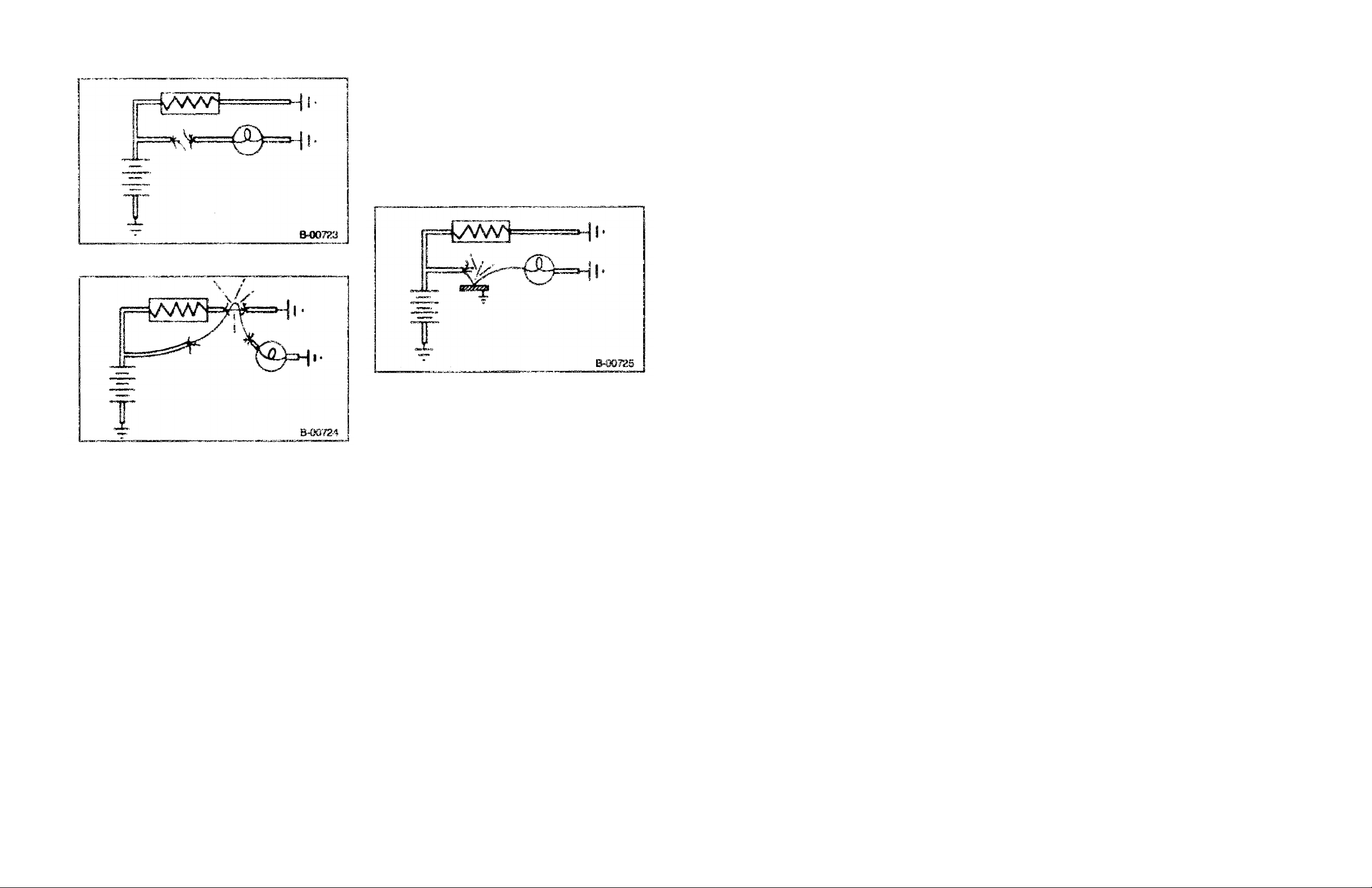
OPEN CIRCUIT (Figure 8)
An open circuit occurs whenever there is a break in the
circuit. The break can be corrosion at the connector, a
wire broken off in a device, or a wire that burned open
from too much current.
SHORT CIRCUIT (Figure 9}
A short circuit happens when the current bypasses part
of the normal circuit. This bypassing is usually caused by
wires touching, salt water in or on a device such as a
switch or a connector or solder melting and bridging
conductors in a device.
WIRING DIAGRAMS 7
WIRING DIAGRAMS 8
Figure 8- -Open Circuit
Figure 9—Short Circuit
ABBREVIATION LIST
The following is a list of abbreviations used in the wiring
diagrams. The abbreviations have been developed in
such a way that their meaning should be clear.
Use this page as a reference to determine the meaning
of an abbreviation if necessary.
A --- Ampere
A/C--- Air Conditioner
ACC --Accessory
A.I.R.---Air Injection Reaction
AIR/COND—Air Conditioner
ALDL—Assembly Line Diagnostic link
ALT—Alternator
AMP—Ampere
ANTI—Anticipate
ASM—Assembly
ASSY- -Assembly
ALIO—Audio
AUTO—-Automatic
AUX—Auxiliary
BAT—Battery
BATT— Battery
B I--LEV—B i-Level
BLK—Biack
BUT- -Belt
BLU-Blue
BOT--Bottom
GROUNDED CIRCUIT(Figure 10)
A ground circuit is like a short circuit but the current
flows directly into a ground circuit that is not part of the
original circuit. This may be caused by a wire rubbing
against the frame or body. Sometimes a wire will break
and fall against metal that is connected electrically to the
ground side of the power supply. A grounded circuit may
also be caused by deposits of oil, dirt and moisture
around connections or terminals, which provide a good
path to ground.
Figure 10—Grounded Circuit
BRK—Brake
BRN--Brown
BU---Backup
BUZZ—Buzzer
CIR/BRK—Circuit Breaker
CIRC- -Circuit
CLSTR- -Cluster
CNTL---Control
COMP----Compartment
COMP—Compressor
CONN—Connector
PONV— Convenience
CTSY—Courtesy
CYL—-Cylinder
DK—Dark
DIAG—Diagnostic
DIM—Dimmer
DIR—Directional
DISC—Discrete
DIST—Distributor
DIV— Diverter
DM—Dome
DR—Door
ECM—Electronic Control Module
EFE—Early Fuel Evaporation
EGR—Exhaust Gas Recirculation
ELEC—Electric
ELEC—Electronic
CNTRL—Control
MOD—Module
ENG-—Engine
EPR—Exhaust Pressure Regulator
ESC—Electronic Spark Control
EST—Electronic Spark Timing
EVRV—Electronic Vacuum Regulator Valve
EXC---Except
F-PUMP—Fuel Pump
FLASH—Flasher
FRT—Front
4WD—Four Wheel Drive
GEN—Generator
GRA—Gray
GRD—Ground
GRN—Green
HAND—Handling
HAZ—Hazard
HD—Heavy Duty
HD LP—Headlamp
HEI—High Energy Ignition
HI—High
HTR—Heater
IAC-Idle Air Control
IGN—Ignition
IL.LUM—Illumination
I/P—Instrument .Panel
INC—Increased
IND—Indicator
INJ —Injector
INST PNL Instrument Pane!
INTER—Interior
LD—Light Duty
LH—Left Hand
LO—Low
LP—Lamp
LPS- -Lamps
LT~~Light
LTR-~Ughter
M—Motor
MAN—Manual
MAP—Manifold Absolute Pressure
MAX---Maximum
MED—Medium
MRKR—Marker
MULT—Multiple
NAT--Natural
NEUT—Neutral
NO—Normally Open
NC—Normaiiy Closed
ORN--Orange
PK—Park
PLR—Puller
PNKf-PInk
PNL—Panel
PPL—Purple
PRESS—Pressure
WR—Power
RCVR—Receiver
REF—Reference
RESIST---Resistance
RM—Right Hand
RPO—Regular Production Option
SEN---Sensor
SEND—Sender
SIG—Signal
SIL—Silver
SKT—-Socket
SOL—Solenoid
SPEEDO—Speedometer
STR—Stripe
SW—Switch
TACH-—-Tachometer
TBI—Throttle Body Injection
TCC-—Torque Converter Clutch
TEMP--Temperature
T/L-—Tail Lamp
TRANS- -Transmission
TYP-- Typical
V—Volt
VAC—Vacuum
VLV—Valve
VSS—Vehicie Speed Sensor
W/—With
W/O—Wttmut
W/S—Windshield
W WASHER—Window Washer
WOO—Window
WHT-White
WRG—-Wiring
YEL—Yellow
DIAGNOSTIC TOOLS
WIRING DIAGRAMS 9
WIRING DIAGRAMS 10
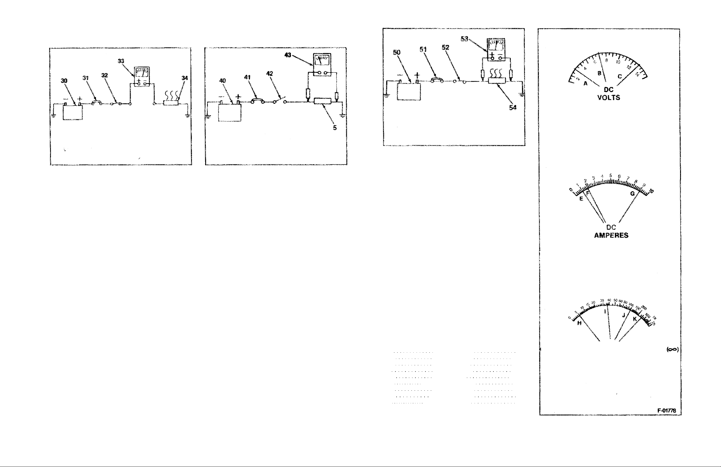
30. Power Source
31 Circuit Breaker
32. Switch (Closed)
33 Ammeter
34. Load
B-06086
Figure 12—Ammeter
UNPOWERED TEST LIGHT (Figure 12)
This tool consists of a 12 volt light with leads. The ends
of the leads usually have alligator clamps, but various
kinds of probes, terminal spades, and special connectors
are used also.
The unpowered test light is used on an open circuit.
One lead of the test light is grounded and the other lead is
moved around the circuit to find the open. Depending on
the physical layout of the circuit, sometimes it will be
easier to start at the power supply and other times it is
easier to start at the Circuit load or ground circuit.
POWERED TEST LIGHT (Figure 11)
This light is a pencil shaped unit with a self contained
battery, a 1 5 volt light bulb, a sharp probe and a ground
lead fitted with an alligator clip.
This test light is used mainly for testing components
that are disconnected from the vehicle power supply. The
power test light is also useful for testing suspected high
resistance points in a circuit such as connectors and
ground circuits that are corroded or loose.
JUMPER
The jumper is usually a long wire with alligator clamps.
A version of the jumper has a fuse holder in it with a 10
Amp fuse. This will prevent damaging the circuit if the
jumper is connected in the wrong way.
The jumper is used to locals opens in a circuit. One
end of the jumper is attached to a power source and then
the other end is attached to the load in the circuit, i.e.;
light, motor. If the load works, try "jumping" to circuit
points that are progressively closer to the power supply.
When the circuit load stops working, the open has been
located.
The jumper is also used to test components in the
circuit such as connectors, switches, and suspected high
resistance points.
40. Power Source
41. Circuit Breaker
42. Switch (Open)
43. Ohmmeter
44. Load
Figure 13 --Ohmmeter
NOTICE: The followmg instruments: Ammeter,
Voltmeter, and Ohmmeter, each have a
particular application for trouble shooting
electrical circuits.
When using a ammeter or voltmeter, and the
value being tested is unknown always use the
highest scale first and work downward to a
midscale reading whenever possible. This will
avoid damage to the Instrument.
B-06087
Never use an ohmmeter in a power circuit, or
as a substitute for a vohmeter or ammeter as
damage to the instrument will result.
AMMETER (Figure 12 and 15)
Disconnect the circuit from the power source before
connecting the ammeter. The ammeter measures the
amount of electrical current, amperes, moving through a
conductor. The ammeter must be placed in series with the
circuit being tested. Be sure that the ammeter's positive
terminal is connected to the positive (battery) side of the
circuit and is negative terminal to the negative (ground)
side of the circuit.
OHMMETER (Figure 13 and 15)
The ohmmeter is an instrument designed to indicate
resistance in ohms, it is used to test the condition of a unit
disconnected from the circuit.
Ohmmeter Calibration
When the ohmmeter probes are connected together, a
circuit is completed causing the meter needle to deflect
The needle should read ZERO ohms, if it does not, rotate
the CAL or ADJ knob to ZERO the needle.
When the probes are held apart, the needle moves to
the maximum (infinite) resistance side of the scale.
The meter is now ready for use. Refer to figure 14 for a
typical application of the ohmmeter.
50. Power Source
VOLTMETER SCALE: 0 Volts through 15 Volts
51. Circuit Breaker
52. Switch (Closed)
53. Voltmeter
54. Load
Figure 14—Voltmeter
VOLTMETER (Figures 14 and 15)
The voltmeter (properly observed) will give the
technician more information than the ammeter, ohmmeter
and test light combined, its application for troubleshooting
here is to measure the electrical pressure (voltage) drop in
a resistance circuit (figure 14).
Io use a voltmeter for troubleshooting an electrical
problem, connect it in parallel with the existing circuit
(figure 10). If the voltmeter is connected in series with the
circuit being tested, the nature of the circuit would be
changed and the reading would have no particular value
or use. Connect the meter terminals according to polarity
as shown in figure 14.
The dash mounted voltmeter (in the vehicle) should
also be observed for monitoring proper operation of the
generator battery cranking motor, and cranking circuit. In
this application, battery voltage drop can be monitored
while the engine is cranking; and after the engine is
running, generator output voltage cars be monitored. This
can be a valuable first step prior to diagosing other
electrical problems.
WIRING HARNESS AND WIRES
Every wire is a specific size with colored or striped
insulation that is indicated on the wiring diagrams.
Insulation colors help to trace circuits and to make proper
connections. Abbreviations and symbols used for
indicating wire insulation colors and patterns are as
follows:
BIK Black BLU Blue
BRN Brown PPL Purple
CHK Check TR Tracer
CR Cross YEL .Yellow
GRN Green // Parallel
NAT Natura! WHT White
SGL Single STR Stripe
ORN Orange PNK Pink
GR Gray DK Dark
Some wires are grouped and taped together or
encased in a split plastic casing. This grouping of wires is
called a harness. For some purposes, it is more practical
to use a single wire protected by a braided tubing called a
loom.
B-06155
AMMETER SCALE: 0 Amperes through 10 Amperes
OHMMETER SCALE: 0 Ohms through Infinity
A = 3 Volts
B = 7 Volts
C = 13 Volts
E = 1 Ampere
F = 1.8 Amperes
G = 9 Amperes
H = 5 Ohms
I = 36 Ohms
J = 115 Ohms
K = 350 Ohms
Figure 15-Meter Scales
WIRING DIAGRAMS 11
WIRING DIAGRAMS 12
Wiring harnesses are joined by using a multiple plug
and receptacle connector block, or a terminal post
chassis junction block. In the instrument panel area
plastic insulated blade-type connectors and screw-type
terminals are used.
Each harness or wire must be held securely in place by
clips or other holding devices to prevent chafing of the
insulation.
WIRE SIZE
Wire size in a circuit is determined by the amount of
current, the length of the circuit and the voltage drop
allowed. Wire size is specified using the metric gage. The
metric gage describes the wire size directly in cross
section area measured in square millimeters.
ON-VEHICLE SERVICE
CIRCUIT MAINTENANCE
AND REPAIR
MAINTENANCE AND REPAIR
All electrical connections must be kept clean and tight.
Loose or corroded connections may cause a discharged
battery, difficult starting, dim lights, and possible damage
to the generator and regulator. Wires must bo replaced if
insulation becomes burned, cracked, or deteriorated.
To splice a wire or repair one that is frayed or broken
always use rosin flux solder to bond the splice and
insulating tape to cover all splices or bare wires.
When replacing wire, it is important that the correct size
wire be used as shown on applicable wiring diagrams or
parts book. Each harness or wire must be held securely in
place to prevent chafing or damage to the insulation due
to vibration.
Never replace a wire with one of a. smaller size or
replace a fusible link with a were of a larger size.
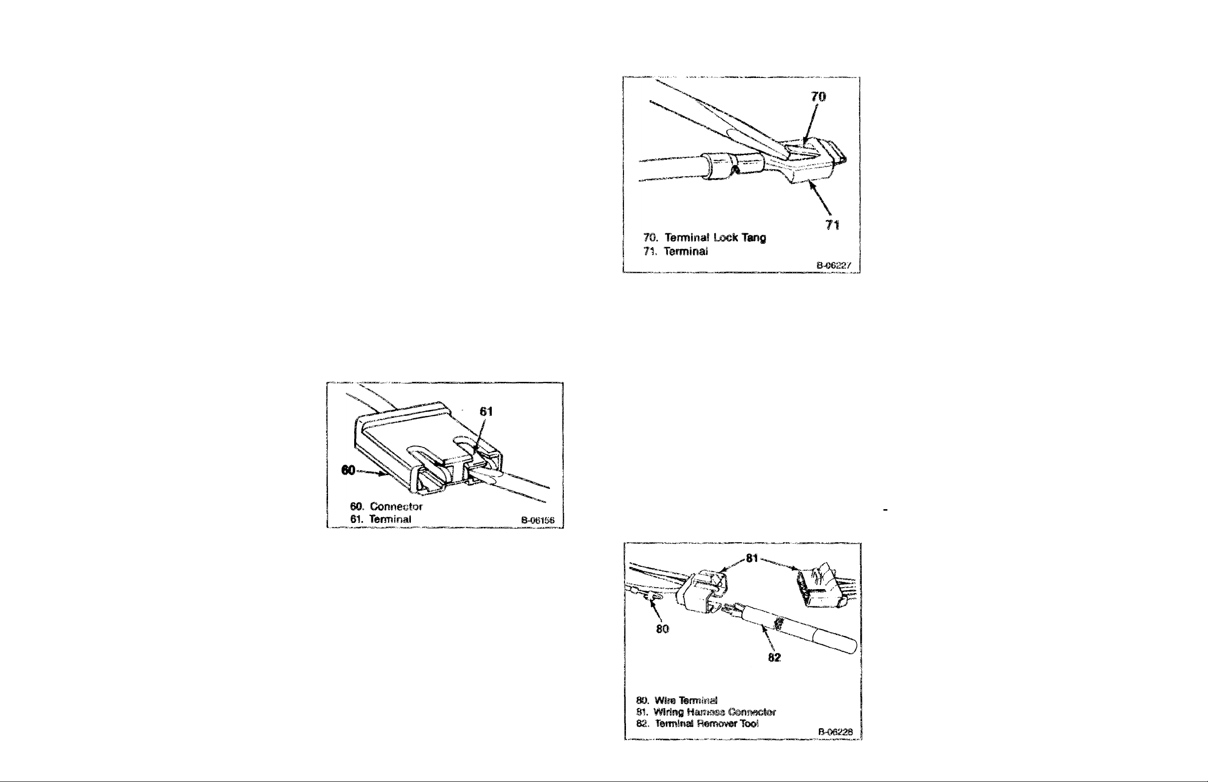
WRING CONNECTOR TERMINAL
REPLACEMENT (BLADE TYPE)
[<>] Remove or Disconnect (Figure 10)
1. Terminal lock tang.
2. Terminal (61).
[><] Install or Connect (Figure 17)
I. Pry up on the tang (70).
2. Terminal into the connector.
WIRE SIZE
CONVERSION TABLE
METRIC AWG
SIZE SIZE
2
(mm)
0.22 24
0.35 22
0.5 20
0.8 18
1.0 16
2.0 14
3.0 12
5.0 10
8.0 8
13.0 6
19.0 4
32.0 2
40.0 1
50.0 0
62.0 00
Figure 16—Removing the Terminals from
the Connector
WIRING CONNECTOR TERMINAL
REPLACEMENT (TWIN LOCK TYPE)
[<>] Remove or Disconnect (Figure 18)
Tool Required:
J-22727 Terminal Remover
1. Connector lock tangs.
2. Terminal lock tangs.
3. Terminal
[><] Install or Connect
1. Pry out the tangs
2. Terminal into the connector.
.
Figure 17—Resetting the Lock Tang
WEATHER-PACK CONNECTORS
Special connectors known as Weather-Pack connectors
(figure 19) require a special tool J-28742 for servicing.
This special tool is required to remove the pin and sleeve
terminals. If removal is attempted with an ordinary pick,
there is a good chance that the terminal will be bent or
deformed. Unlike standard blade-type terminals, these
terminals cannot be straightened once they are bent.
Mate sure that the connectors are property seated and
all of the sealing rings in place when connecting the
leads. The hinge-type flap provides a back-up, or
secondary locking feature for terminals. They are used to
improve the connector reliability by retaining the terminals
if the small terminal lock tangs are not positioned
properly.
Molded-on-connectors require complete replacement of
the connection. This means splicing a new connector
assembly into the harness. Environmental connections
cannot be replaced with standard connections.
Instructions are provided with the Weather-Pack
connector and terminal packages.
With the low current and voltage levels found in some
circuits, it is important that the best possible bond at all
wire splices be made by soldering the splices.
Use care when probing the connections or replacing
terminals in them, it is possible to short between opposite
terminals. If this happens to the wrong terminal part, it is
possible that damage may be done to certain
components. Always use jumper wires between
connectors for circuit checking. Never probe through the
Weather-Pack seals.
When diagnosing for possible open circuits, it is often
difficult to locate them by sight because oxidation or
terminal misalignment are hidden by the connectors.
Merely wiggling a connector on a sensor or in the wiring
harness may correct the open circuit condition. This
should always be considered when an open circuit is
indicated while troubleshooting. Intermittent problems
may also be caused by oxidized or loose connections.
METRl-PACK CONNECTORS
The Metri-Pack connectors use a pull-to-seat type
terminal, as shown in figure 19. The special tool required
to remove the terminal is J-35689-A terminal remover. If
removal is attempted with an ordinary pick, there is a
good chance that the terminal will be bent or deformed.
Refer to figure 19.
[<>] Remove or Disconnect (Figure 19)
Tool Required:
J-28742 Terminal Remover
1. Primary lock (121) by lifting.
2. Connector sections.
3. Secondary lock (125) by spreading the sides of the
hasp, thus clearing the staples and rotating the
hasp (127).
4. Terminal (131) by using J-28742 (128).
* Snip off the old terminal assembly.
5. 5 mm of the wire insulation (130).
[^] Clean
Terminal barrel (124).
[><] Install or Connect (Figure 19)
1. Terminal insulator (134) on the wire. Slide the
insulator back on the wire about 8 cm (3 inches).
2. Terminal (131) on the wire.
* Roll crimp (132) and solder the terminal
3. Terminal insulator (134) and the roll crimp (133).
4. Terminal into the connector.
5. Secondary lock (125).
6. Connector sections until the primary lock (121)
engages.
METRI-PACK CONNECTOR REPLACEMENT
[<>] Remove or Disconnect (Figure 19)
Tool Required
J-35689-A Terminal Remover
1. Primary lock (121) by lifting.
2. Connector Body (1ST).
3. Connector seat (120) by pulling the seal back onto
the wires away from the connector body (137). Figure 18—Twin Lock Connector Terminal

WIRING DIAGRAMS 13
90. Jacket
91. Twisted Wires
92. Splice Clip
93. Crimp and Solder
94. Electrical Tape Wrap
95,. Outer Electrical Tape Wrap.
B-06230
Figure 20 Twisted Wire Repair
4. Terminal (138) by inserting J-35689 (139) into the
connector body (137) to depress the locking tang
(138), then push the wire and terminal through the
connector body (figure 20).
• Snip off the old terminal unless the terminal is to be
reused, reshape the locking tang.
5. 5mm (0.2-inch) of the wire insulation (130).
WIRING DIAGRAMS 14
100. Jacket
101. Aluminum/Mylar Tape
102. Drain Wire
103. Splice Clip
104. Crimp and Solder
105. Electrical Tape Wrap
106. Drain Wire Splice Clip, Crimped And Soldered.
107. Outer Electrical Tape Wrap.
B-06231
120. Connector Seal
121. Primary Lock
122. Secondary Lock Staple
123. Secondary Lock
124. terminal Barrel
125. Secondary Lock
128. Lock Opened
127. Lock Opened
128. J-28742 Terrninal Remover
129. Wire
Figure 19—Weather-Pack and Metri-Pack Connectors
VIEW B
130. 5 mm (0.2 inch)
131. Terminal
132. Roll Crimp
133. Roll Crimp
134. Terminal Insulator
136. Metri-Pack Series 150 Female Terminal
137. Connector Body
138. Locking Tang
139. J-35689 Terminal Remover
F-02349
* Terminal cavity of the connector body.
[><] Install or Connect (Figure 19)
1. Terminal (136) on the wire.
• Crimp and solder the terminal.
2. Terminal (136) into the connector cavity by pulling
the wire on the seal side of the connector until the
locking tang (138) is fully seated.
3. Seal (120) by pressing the seal into the connector
body (137) until it is fully seated.
4. Connector until the primary lock (121) engages.
WIRING REPAIR
The wire repair is very important for the continued
reliable operation of the vehicle. This repair must be done
as described in the following procedures.
Twisted Wires (Figure 20)
[<>] Remove or Disconnect
1. Jacket (30).
2. Twisted wires (91).
Figure 21 —Twisted/Shielded Wire Repair
3. Insulation from the wire.
[><] Install or Connect
1. Splice clip (93).
• Crimp.
• Solder.
2. Electrical tape wrap (94) on wires.
3. Outer electrical tape wrap (95).
Twisted Wires/Shielded Cable (Figure 21)
[<>] Remove or Disconnect
1. Jacket (100).
2. Unwrap aluminum/mylar tape (101).
3. Drain wire (102).
A. Leads.
5, Insulation on the leads.
[><] Install or Connect
1. Splice clips (103).
2. Crimp and solder the splice clips (104).
3. Electrical tape (105) on the splices.

4. Aluminum/mylar tape by wrapping and taping.
5. Drain wire with a splice clip (106). Crimp and solder
the splice clip.
6. Outer jacket electrical tape wrap (107).
SPECIAL TOOLS
WIRING DIAGRAMS 15
1 Weather-Pack II Terminal Remover
2. Electrical Terminal Remover
3. Windshield Antenna Tester

1989 R/V TRUCK
PAGE DESCRIPTION
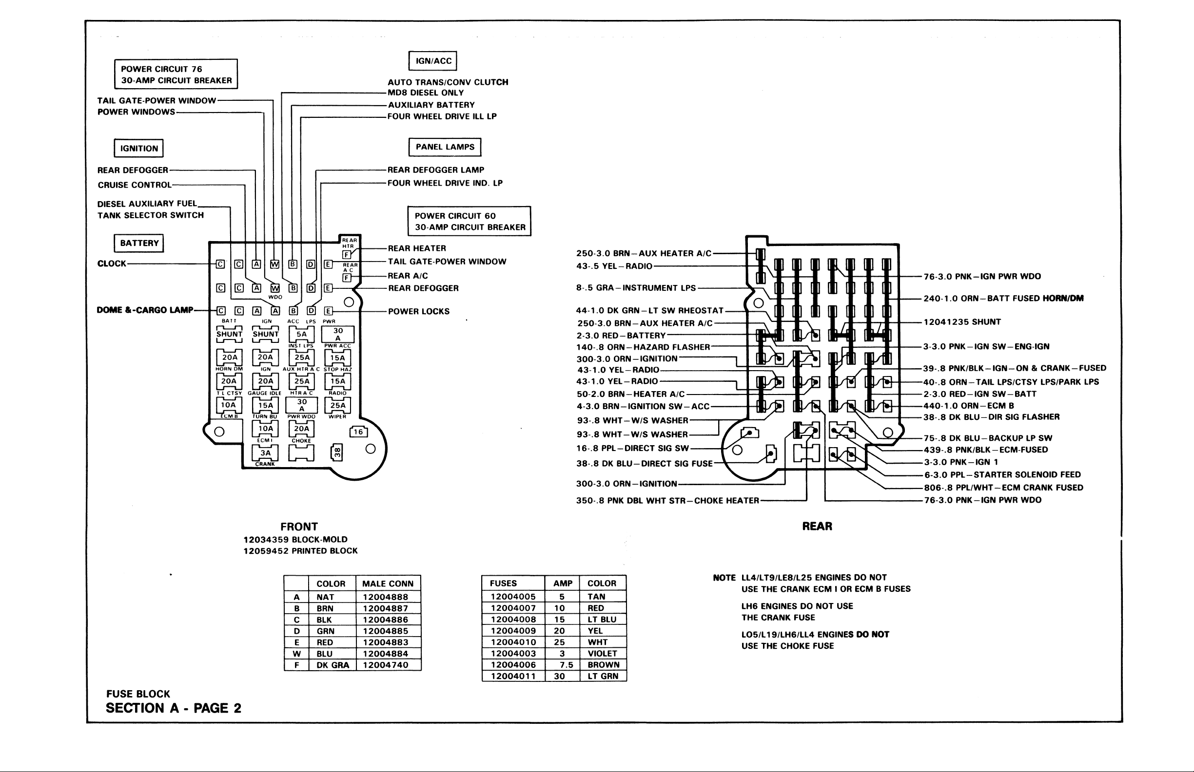
2 FUSE BLOCK DETAIL
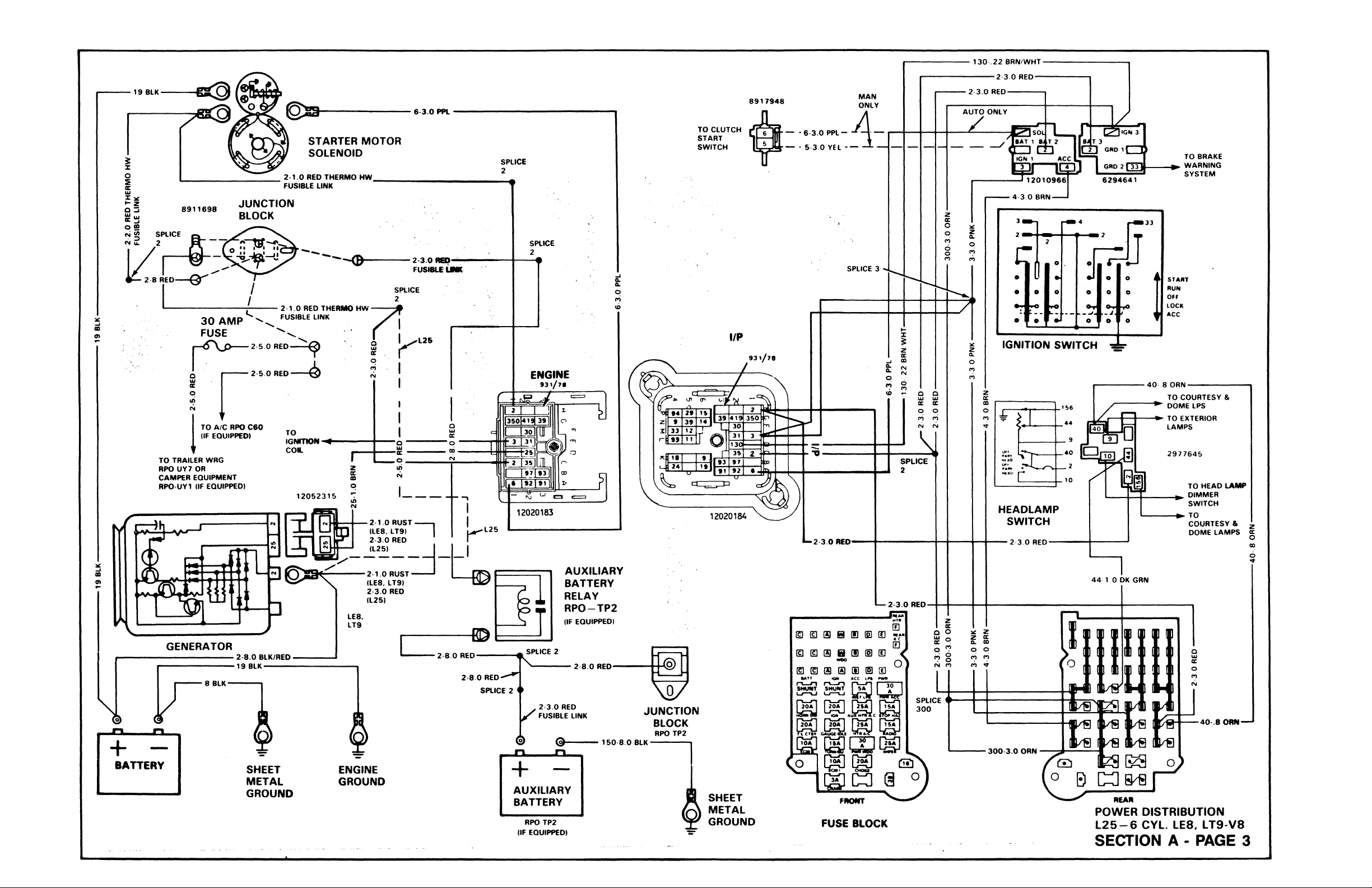
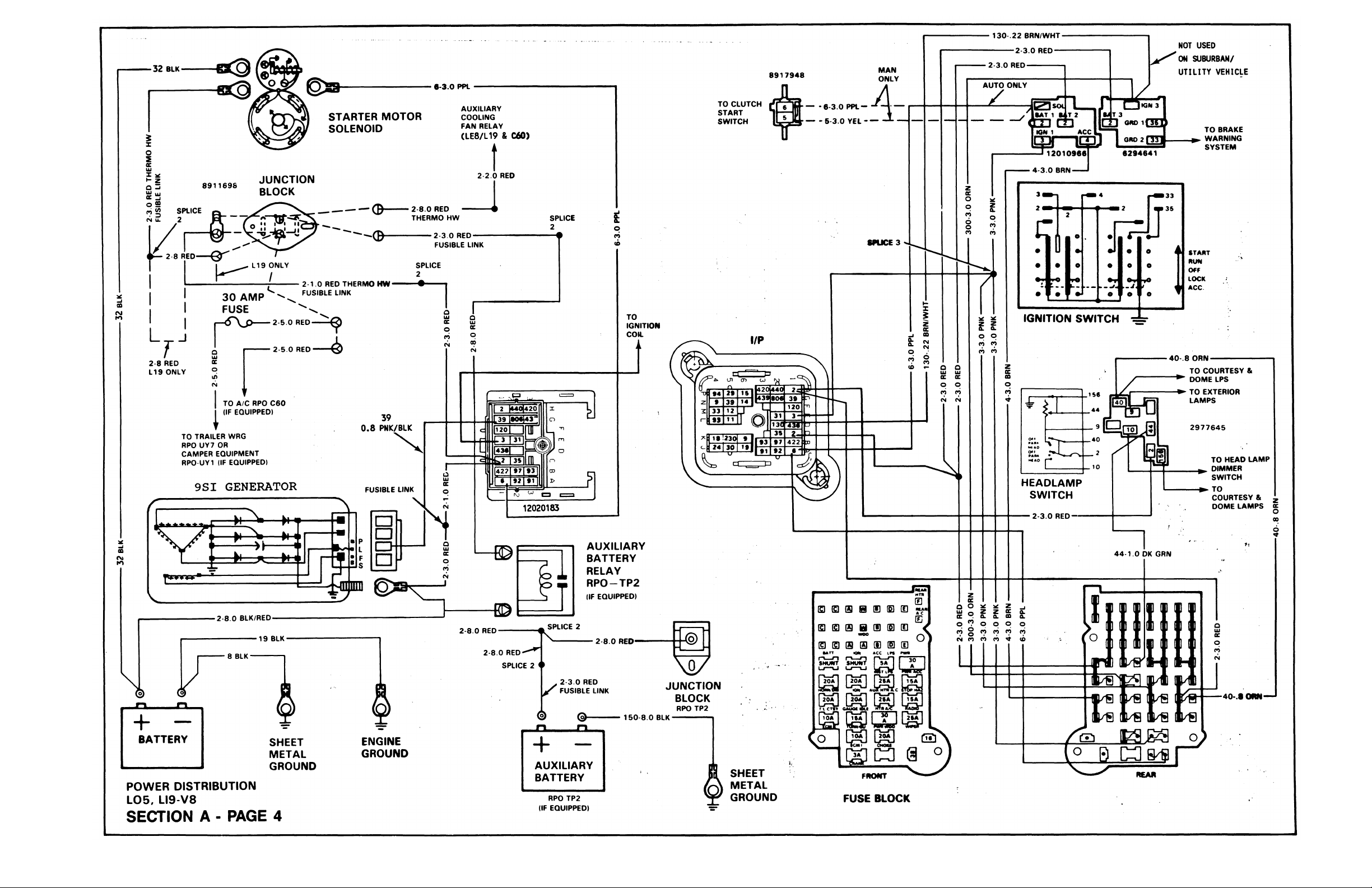
3-4 POWER DISTRIBUTION (GASOLINE)
5 POWER DISTRIBUTION (DIESEL)
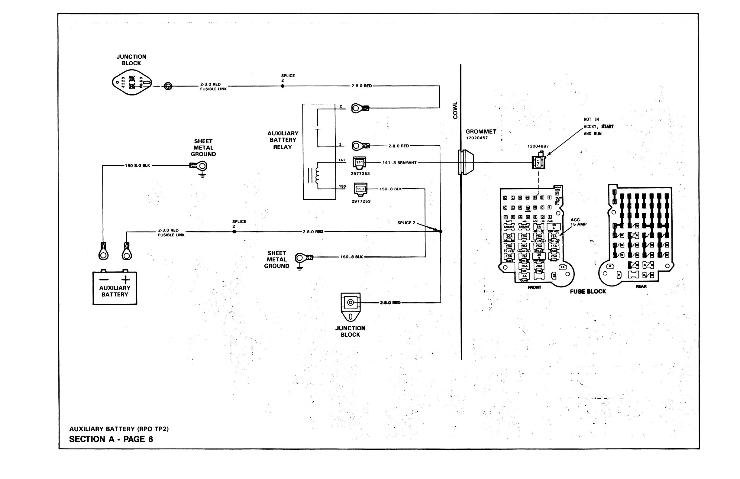
6 AUXILIARY BATTERY (TP2)
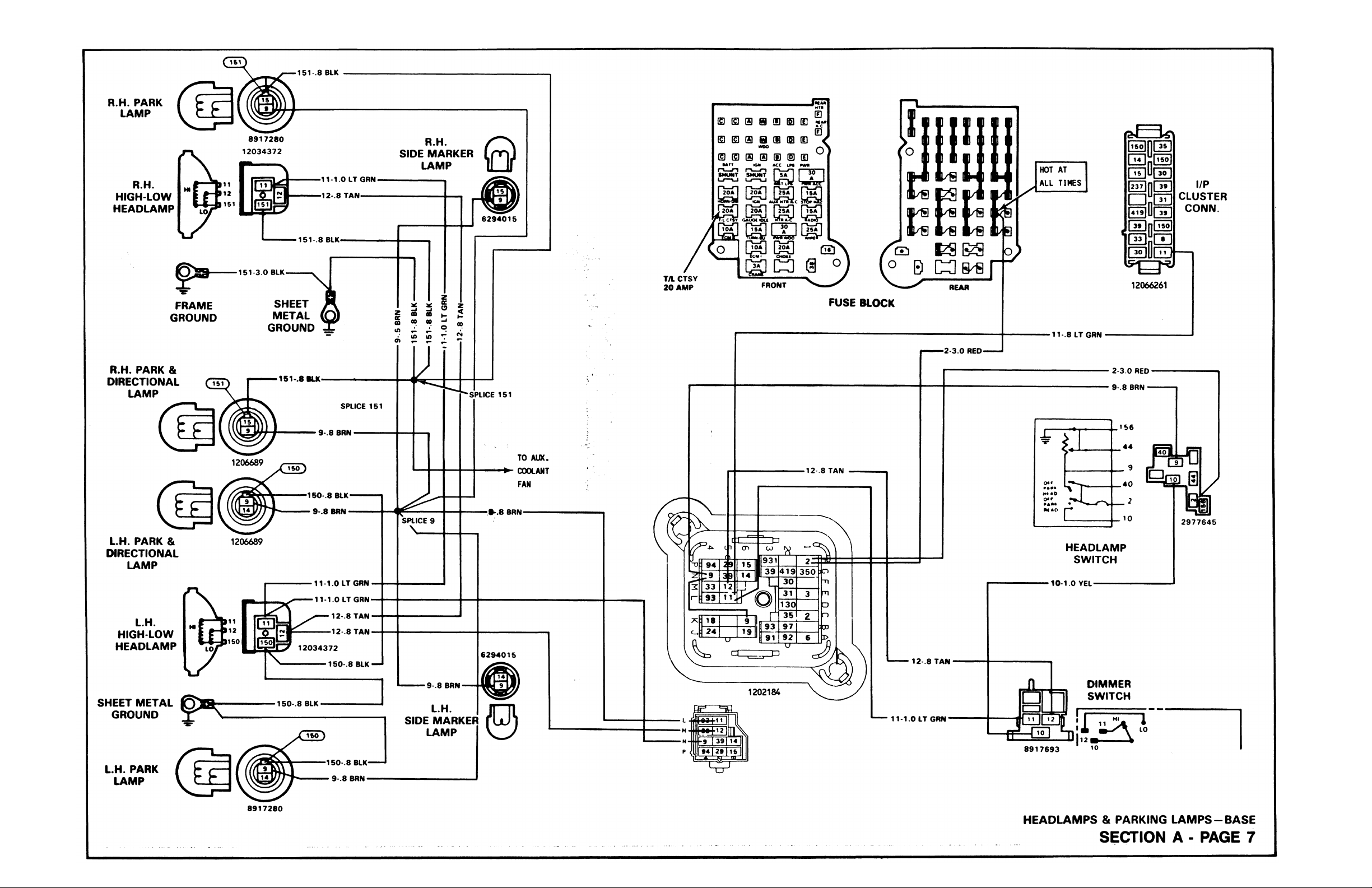
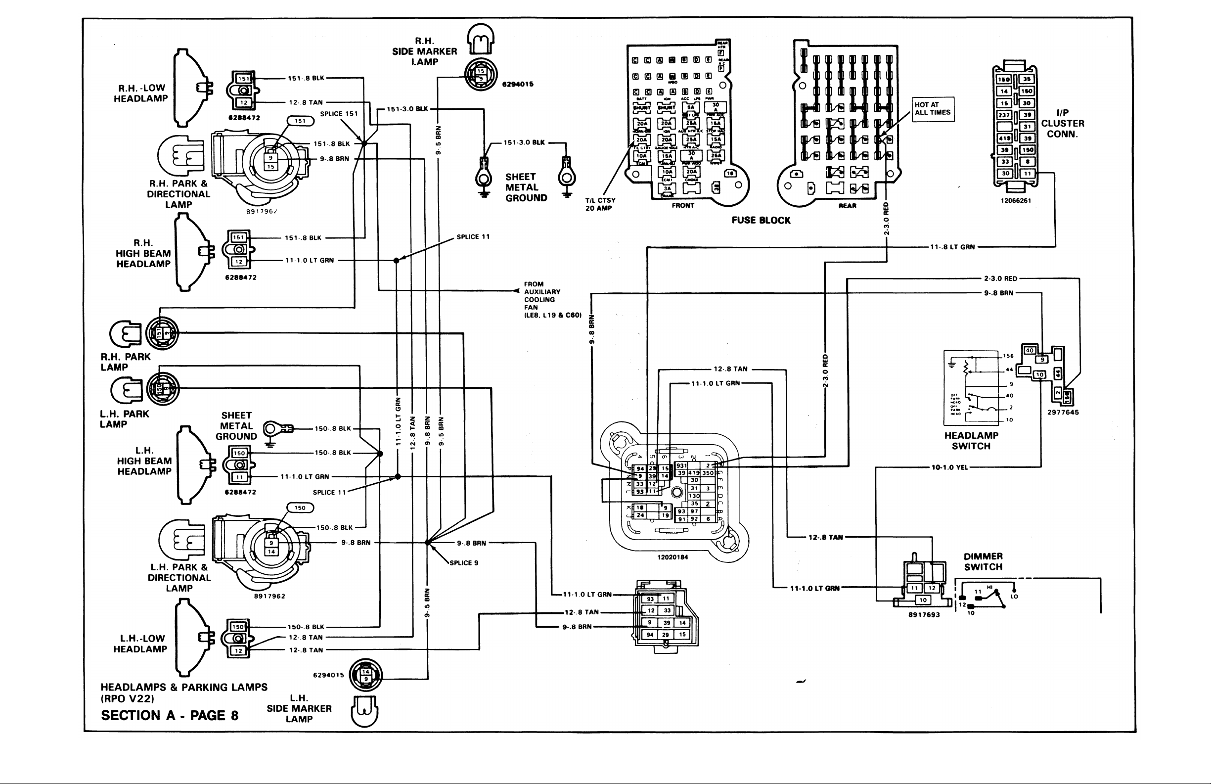
7-8 HEADLAMPS & PARKING LAMPS
9-10 MARKER LAMPS
11 ROOF MARKER LAMPS
12-14 HAZARD LAMPS
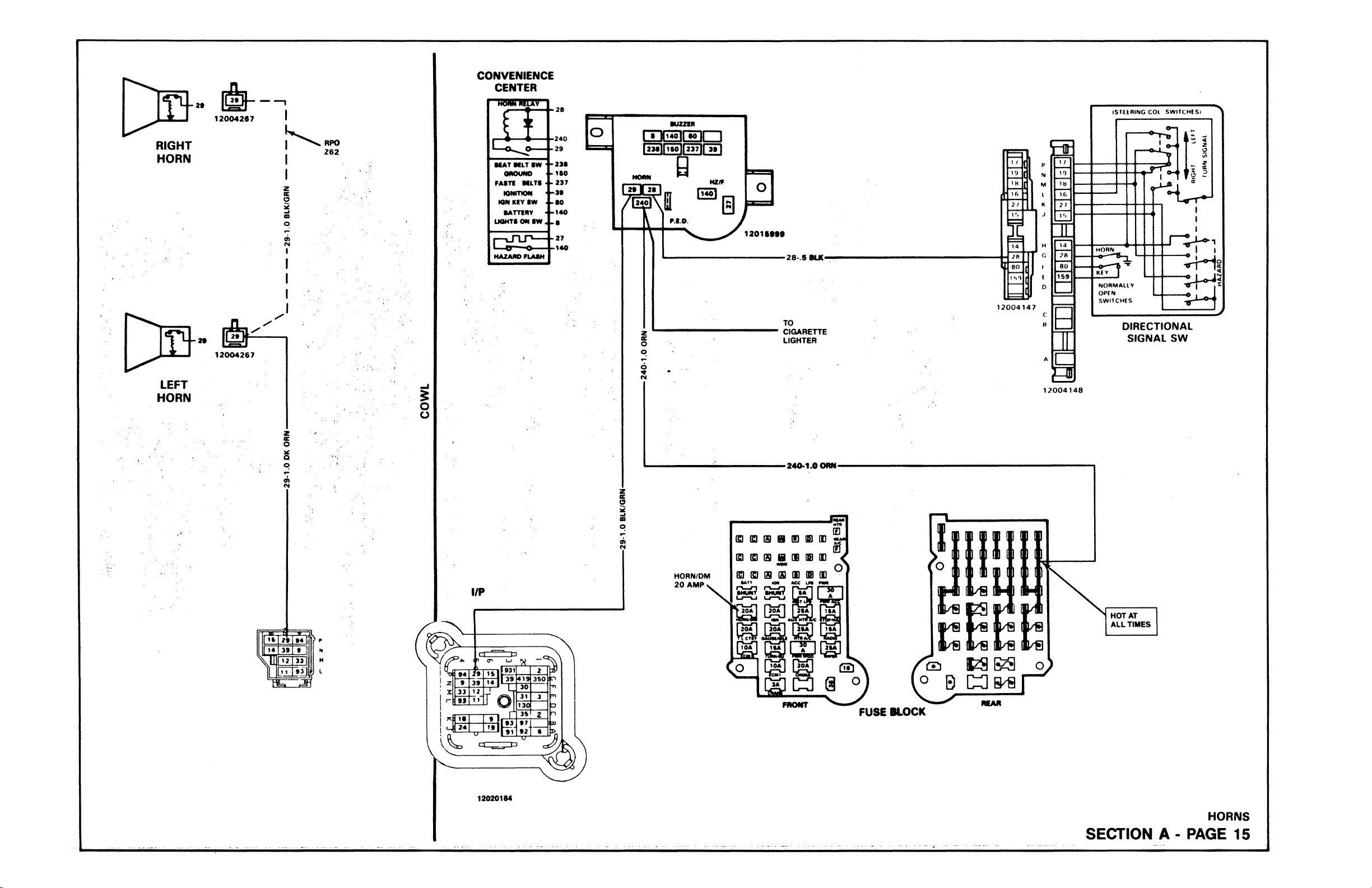
15 HORN
16-17 DIRECTIONAL LAMPS
18 START (8 CYL.) I..25, (8 CYL,) LE8, LT9
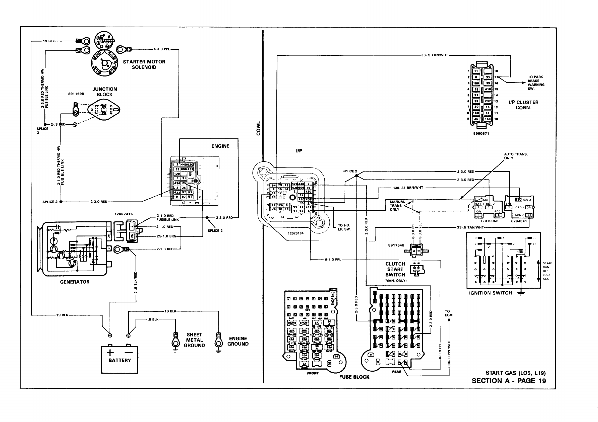
19 START (8 CYL.) LO5, L19
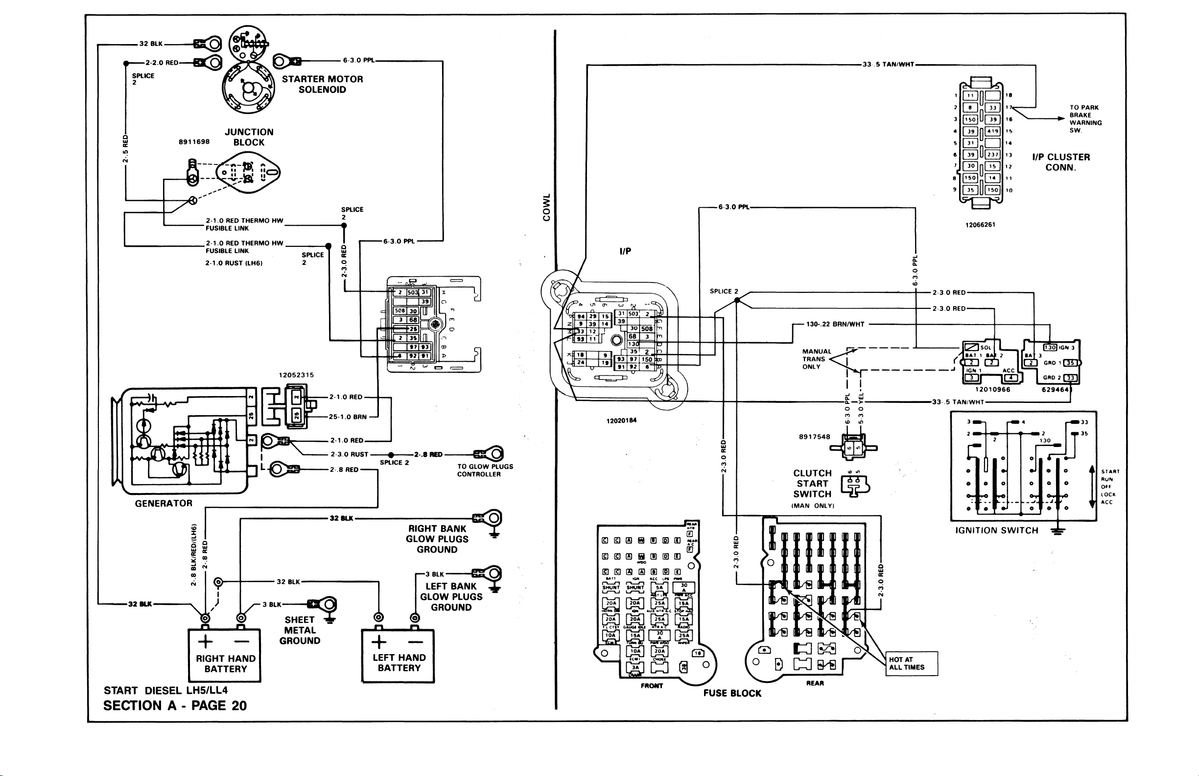
20 START (DIESEL) LL4, LH5
21 IGNITION (6 CYL.) L25
22-23 IGNITION (8 CYL.) LE8, LT9
PAGE
43 ECM CHART (DIESEL)
44-45 ELECTRONIC CONTROL MODULE (ECM)-OUTPUTS (DIESEL)
46 ELECTRONIC CONTROL MODULE (ECM)-INPUTS (DIESEL)
47 TRANSMISSION CONVERTER CLUTCH DETENT SOLENOID
48 AUTOMATIC TRANSMISSION KICKDOWN SOLENOID (M40)
49 AIR CONDITIONING (C60)
50 REAR AIR CONDITIONING (C69)
51 HEATER
52 AUXILIARY HEATER (C36)
53 INSTRUMENT PANEL LAMPS
54-55 INSTRUMENT PANEL GAGES
56-57 INDICATOR LAMPS
58 SEAT BELT WARNING BUZZER
59 BRAKE WARNING SYSTEM
60 FOUR-WHEEL DRIVE INDICATOR LAMP
DESCRIPTION
24 IGNITION (8 CYL.) LO5, LT9
25 THROTTLE BODY INJECTION
26 HOT FUEL HANDLING
27-28 GLOW PLUGS (DIESEL)
29-30 ENGINE CONTROLS (DIESEL)
31 FUEL CONTROL & IDLE AIR CONTROL (8 CYL„) LO5, L19
32 AUXILIARY COOLANT FAN
33-34 AUXILIARY FUEL TANK (NL2)/FUEL TANK SELECTOR SWITCH
35-37 EMISSION CONTROLS
38-39 ELECTRONIC CONTROL MODULE (ECM)-INPUTS (8 CYL.) LO5, L19
40-41 ELECTRONIC CONTROL MODULE (ECM)-OUTPUTS (8 CYL.) LO5, L19
42 ECM CHART (8 CYL.)
61 CRUISE CONTROL (K34)
62 DOME LAMPS
63 CARGO LAMP (UF2)
64 RADIO EQUIPMENT (UM6. UP8)
65 RADIO EQUIPMENT (U63)
66-67 POWER WINDOWS (A31)
68 POWER REAR WINDOW (A33)
69 REAR DEFOGGER (C49)
70-71 POWER DOOR LOCKS
72 WIPER/WASHER
73 PULSE WIPER/WASHER (CD4)
74-76 BACKUP LAMPS
77-80 TAIL LAMPS
81-84 LICENSE LAMPS
85 CAMPER & TRAILER WIRING
SECTION A - PAGE 1
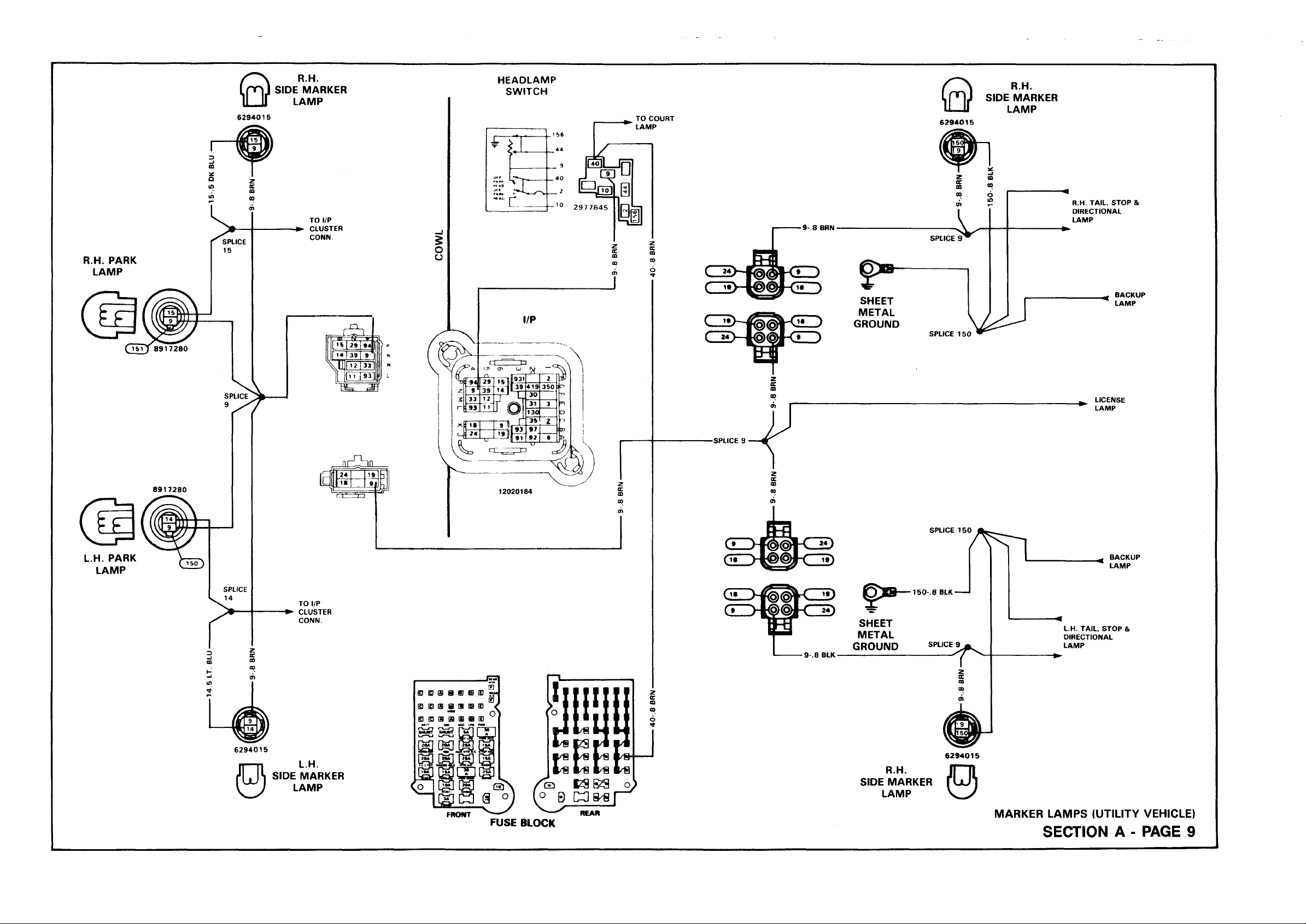
R.H. PARK
LAMP
0
6294015
R.H.
SIDE MARKER
LAMP
TO l/P
► CLUSTER
CONN.
HEADLAMP
SWITCH
9 .8 BRN
SPLICE 9
R.H.
SIDE MARKER
LAMP
R.H. TAIL. STOP &
DIRECTIONAL
LAMP
J
E 3
24
18
SHEET
BACKUP
LAMP
METAL
GROUND
19
D
9
1
SPLICE
SPLICE 150
150 .8 BLK
150
^ LICENSE
LAMP
BACKUP
LAMP
6294015
0
L.H.
SIDE MARKER
LAMP
FRONT
FUSE BLOCK
REAR
9 .8 BLK-
SHEET
METAL
GROUND
R.H.
SIDE MARKER
LAMP
SPLICE 9
L.H. TAIL. STOP &
DIRECTIONAL
LAMP
MARKER LAMPS (UTILITY VEHICLE)
SECTION A - PAGE 9
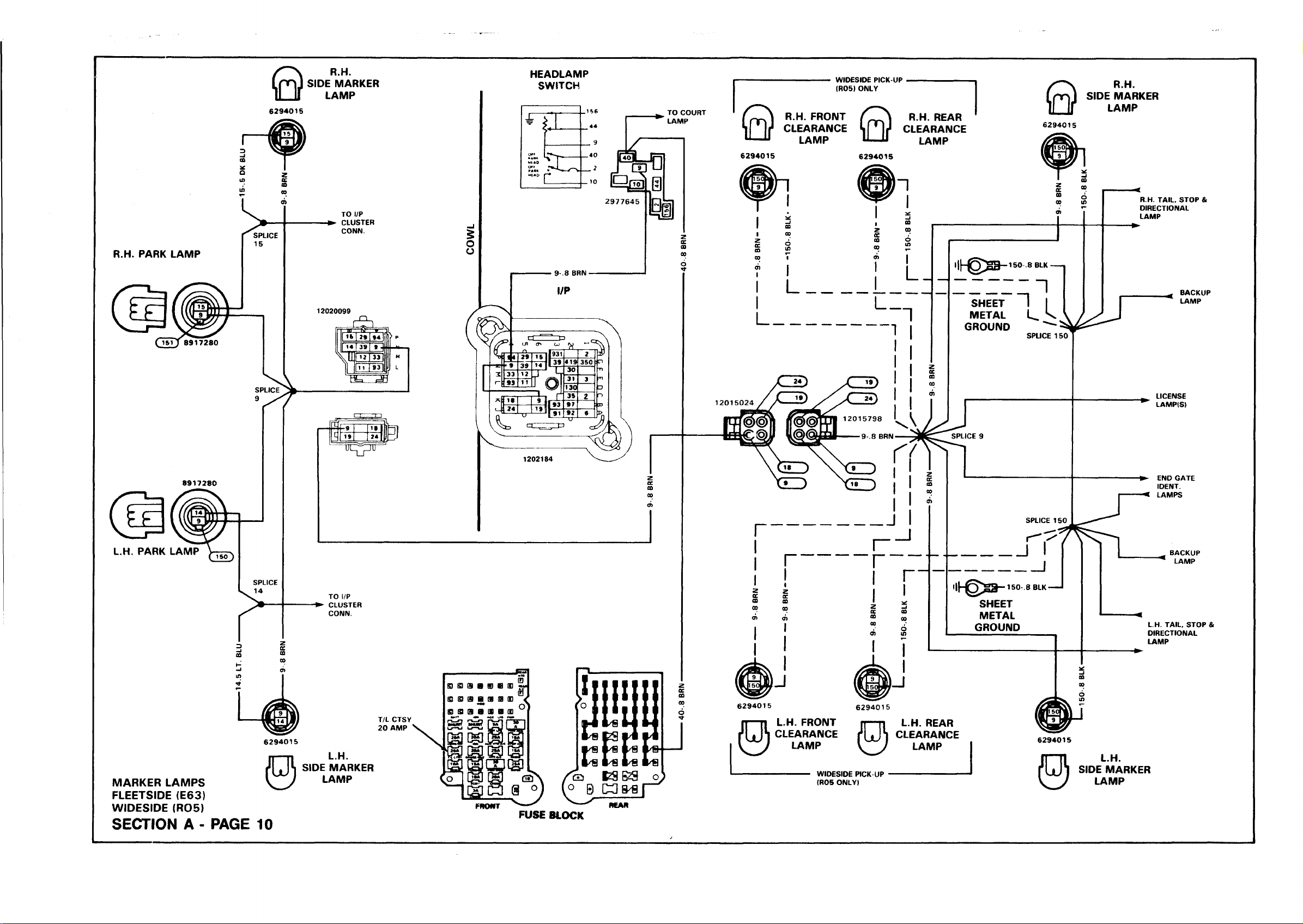
R.H. PARK LAMP
0
6294015
R.H.
SIDE MARKER
LAMP
HEADLAMP
SWITCH
R.H. FRONT /^ " T \ R.H
CLEARANCE U M i* CLE /
0
6294015
$
O
O
LAMP U— U i i
WIDESIDE PICK-UP
(R05) ONLY
6294015
. REAR
CLEARANCE
LAMP
'lh © S § -
150 .8 BLK ■
R.H.
SIDE MARKER
LAMP
R.H. TAIL. STOP &
DIRECTIONAL
LAMP
U 931
J L
1 93
J>| 91
1202184
i b 9
o l
0 >
41 9
30
31
130
35
97
92
T7
2
35 0 :
3
z
C
L
SHEET n
L
:
1201
METAL L.
GROUND
i i h g > a -
SHEET
METAL
GROUND
1
SPLICE 1!
BACKUP
LAMP
LICENSE
LAMP(S)
L.H. TAIL. STOP &
DIRECTIONAL
LAMP
6294015
MARKER LAMPS
FLEETSIDE (E63)
WIDESIDE (R05)
SECTION A - PA G E 10
0
L.H.
SIDE MARKER
LAMP
T/L CTSY
20 AMP
E3 S) GS a B e OD
S3 S) ffl S O IB (D
83 ffl 9 a IB O QD
Lr—u i-r-xj
[g ][g ]
FRONT
FUSE BLOCK
REAR
6294015
0
L.H. FRONT
CLEARANCE
LAMP
WIDESIDE PICK UP
(R05 ONLY)
L.H. REAR
CLEARANCE
LAMP
6294015
0
L.H.
SIDE MARKER
LAMP

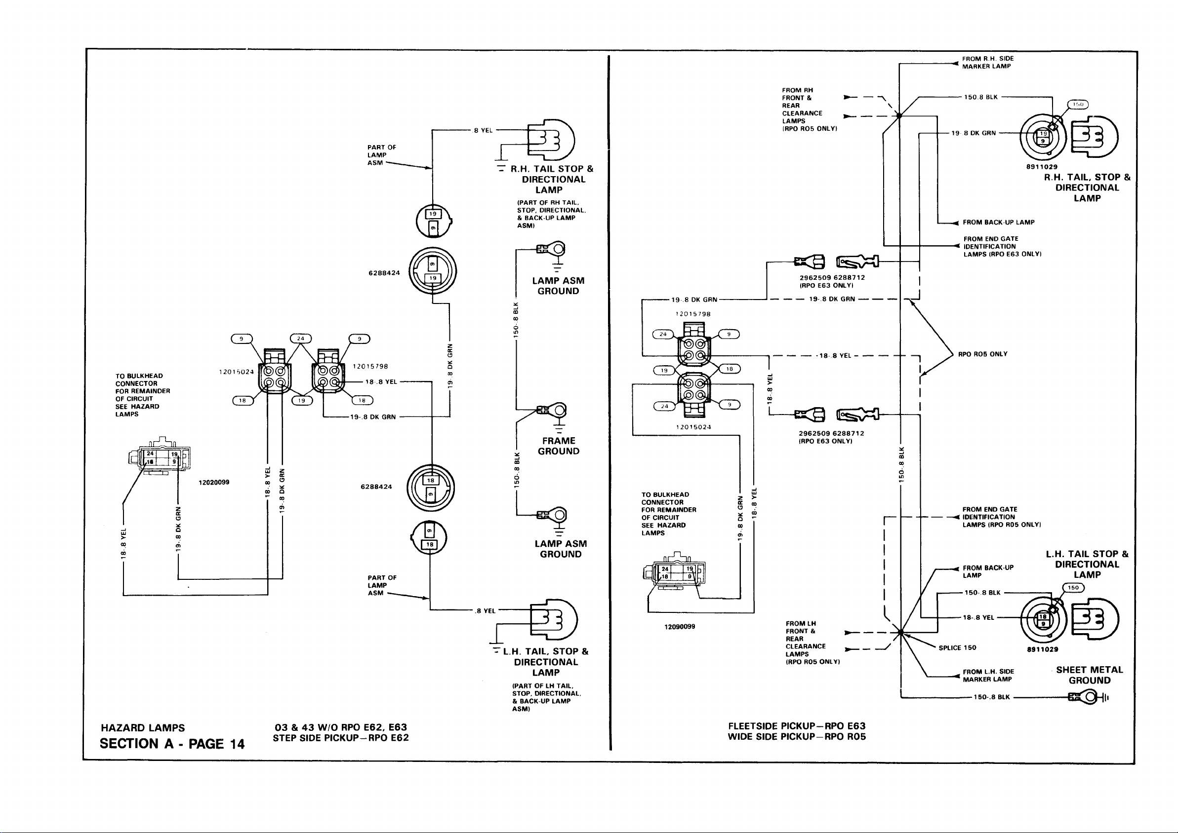
FROM R.H SIDE
MARKER LAMP
TO BULKHEAD
CONNECTOR
FOR REMAINDER
OF CIRCUIT
SEE HAZARD
LAMPS
ji d l h i i
2 4
,H
1
fr-r— i —i
FROM RH
FRONT &
REAR
CLEARANCE
LAMPS
(RPO R05 ONLY)
T R.H. TAIL STOP &
DIRECTIONAL
LAMP
(PART OF RH TAIL.
STOP, DIRECTIONAL.
& BACK UP LAMP
ASM)
6288424
LAMP ASM
GROUND
1 2 0 1 6 0 2 4
12015798
18 .8 YEL
19 8 DK GRN
FRAME
1 9
3
9
iJ
12020099
6288424
GROUND
Q)
TO BULKHEAD
CONNECTOR
FOR REMAINDER
OF CIRCUIT
SEE HAZARD
LAMPS
2962509 6288712
(RPO E63 ONLY)
19 .8 DK GRN
-18 .8 YEL -
2962509 6288712
(RPO E63 ONLY)
150 8 BLK
19 8 DK GRN
8911029
^ FROM BACK UP LAMP
FROM END GATE
-< IDENTIFICATION
LAMPS (RPO E63 ONLY)
RPO R05 ONLY
FROM END GATE
IDENTIFICATION
LAMPS (RPO R05 ONLY)
R.H. TAIL, STOP &
DIRECTIONAL
LAMP
LAMP ASM
GROUND
j i ii h a
24,
,1 8
IV
----------
1
19\
iJ
FROM BACK UP
LAMP
150 .8 BLK
L.H. TAIL STOP &
DIRECTIONAL
LAMP
HAZARD LAMPS
SECTION A - PAGE 14
03 & 43 W/O RPO E62, E63
STEP SIDE PICKUP-RPO E62
.8 YEL
I
©
~ L.H. TAIL, STOP &
DIRECTIONAL
LAMP
(PART OF LH TAIL.
STOP, DIRECTIONAL,
& BACK-UP LAMP
ASM)
12090099
FROM LH
FRONT &
REAR
CLEARANCE
LAMPS
(RPO R05 ONLY)
FLEETSIDE PICKUP-RPO E63
WIDE SIDE PICKUP—RPO R05
18-.8 YEL
SPLICE 150
FROM L.H. SIDE
MARKER LAMP
8911029
SHEET METAL
GROUND
150.8 BLK
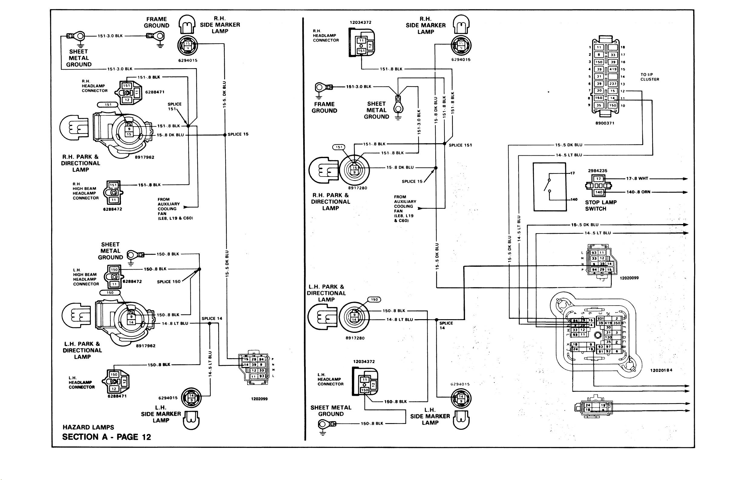
— f iS ^
SHEET
METAL
GROUND
-----
51 3.0 BLK
1
FRAME
GROUND
R.H.
SIDE MARKER
LAMP
SPLICE 15
R.H.
HEADLAMP
CONNECTOR
(5
FRAME
GROUND
12034372
m
g g y
151 3.0 BLK
METAL
GROUND
151 .8 BLK
SHEET
R.H.
SIDE MARKER
LAMP
6294015
E D n a
t z f e
ISO
39
41 9
Ha
0 D
QElnDD
S C D
IhmJ
12066261
TO l/P
CLUSTER
R.H. PARK &
DIRECTIONAL
LAMP
R.H.
HIGH BEAM
HEADLAMP
CONNECTOR
L.H
HIGH BEAM
HEADLAMP
CONNECTOR
L.H. PARK &
DIRECTIONAL
LAMP
6288472
SHEET
METAL
GROUND
151 .8 BLK
150.8 BLK
150 .8 BLK
FROM
AUXILIARY
COOLING
FAN
(LE8. L19 & C60)
150 .8 BLK
SPLICE
150.8 BLK
14 .8 LT BLU
-----
SPLICE 14
R.H. PARK &
DIRECTIONAL
LAMP
L.H. PARK &
DIRECTIONAL
LAMP
8917280
15 18 BLK
15 .8 DK BLU
SPLICE „ /
FROM
AUXILIARY
COOLING ,
FAN
(LE8, L19
& C60)
SPLICE 151
15 .5 DK BLU
-14 .5 LT BLU-
15 .5 DK BLU
14 .5 LT BLU
931
41 9
39
30
L
31
D ]
130
35
r
97
93
92'
91
12020099
2
350 :
3
2
;
<
12020184
L.H
HEADLAMP
CONNECTOR
6288471
SIDE MARKER
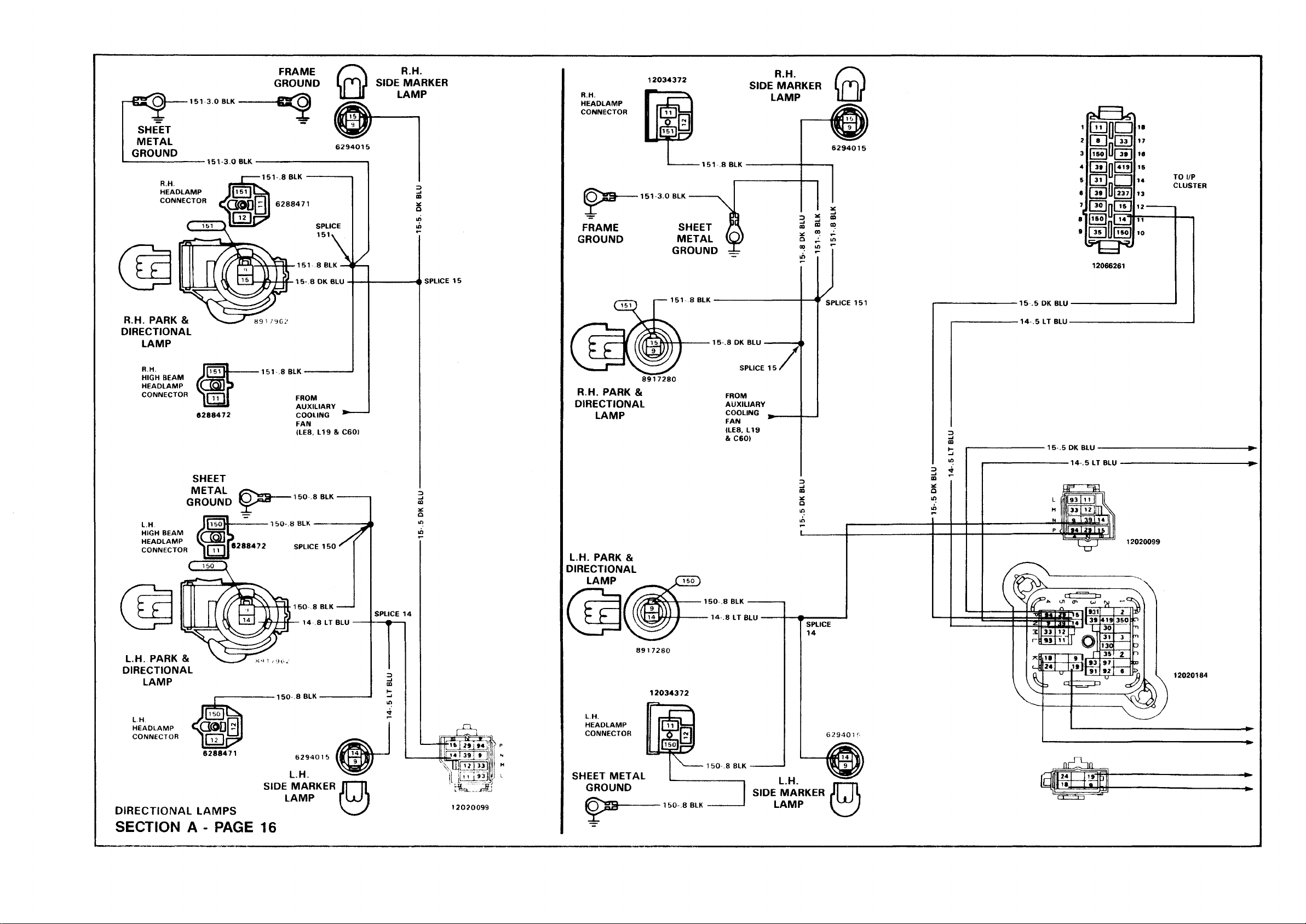
DIRECTIONAL LAMPS
SECTION A - PAGE 16
6294015
L.H.
LAMP
j * 139 yy i
\IU h » i13 i
I t * i-S:
12020099
... nr^hfi
£ 1 H
—
------------——
..
------------------------------------
..
ED G ) (5 H ffl IE E « «
(s si a a ® e e i
G3 (3 (3 GB QD SD OB
•ATT (OH ACC lf » PWA
•MOW? «Hu£? fsA
«oo O
E
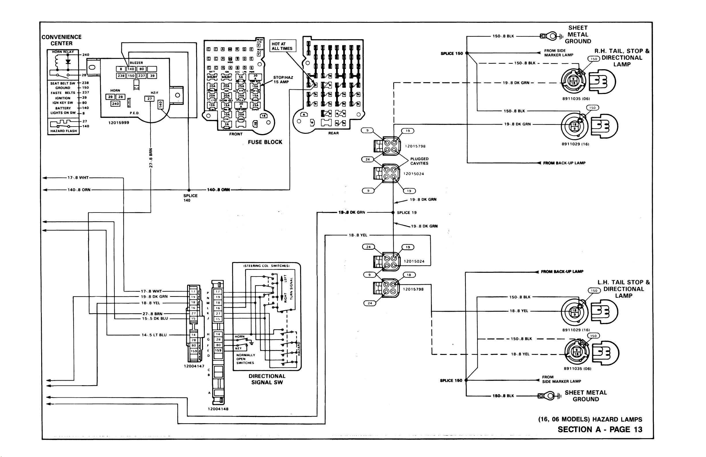
SHEET
150 .8 BLK
FUSE BLOCK
.
SPLICE 150
150 .8 BLK -
19 .8 DK GRN -
FROM SIDE
MARKER LAMP
METAL
GROUND
R.H. TAIL, STOP &
DIRECTIONAL
LAMP
r
DIRECTIONAL
FLASHER
16 .8 PPL
Iz S Bz S
C 3
REAR
-38- 8 DK BLU-
(STEERING COL SWITCHES)
19 .8 DK GRN
18 .8 YEL
150 .8 BLK
19 .8 DK GRN
8911029 (16)
FROM BACK UP LAMP
19 .8 DK GRN
SPLICE 19
.19 8 DK GRN
12015024
FROM BACK-UP LAMP
19-.8 DK GRN
18 .8 YEL
16 .8 PPL
15 .5 DK BLU
14 .5 LT BLU
----
-----
12004147
12004148
DIRECTIONAL
SIGNAL SW
12015798
L
SPLICE
150 .8 BLK
150-.8 BLK
18-.8 YEL
- 150-.8 BLK
18 .8 YEL
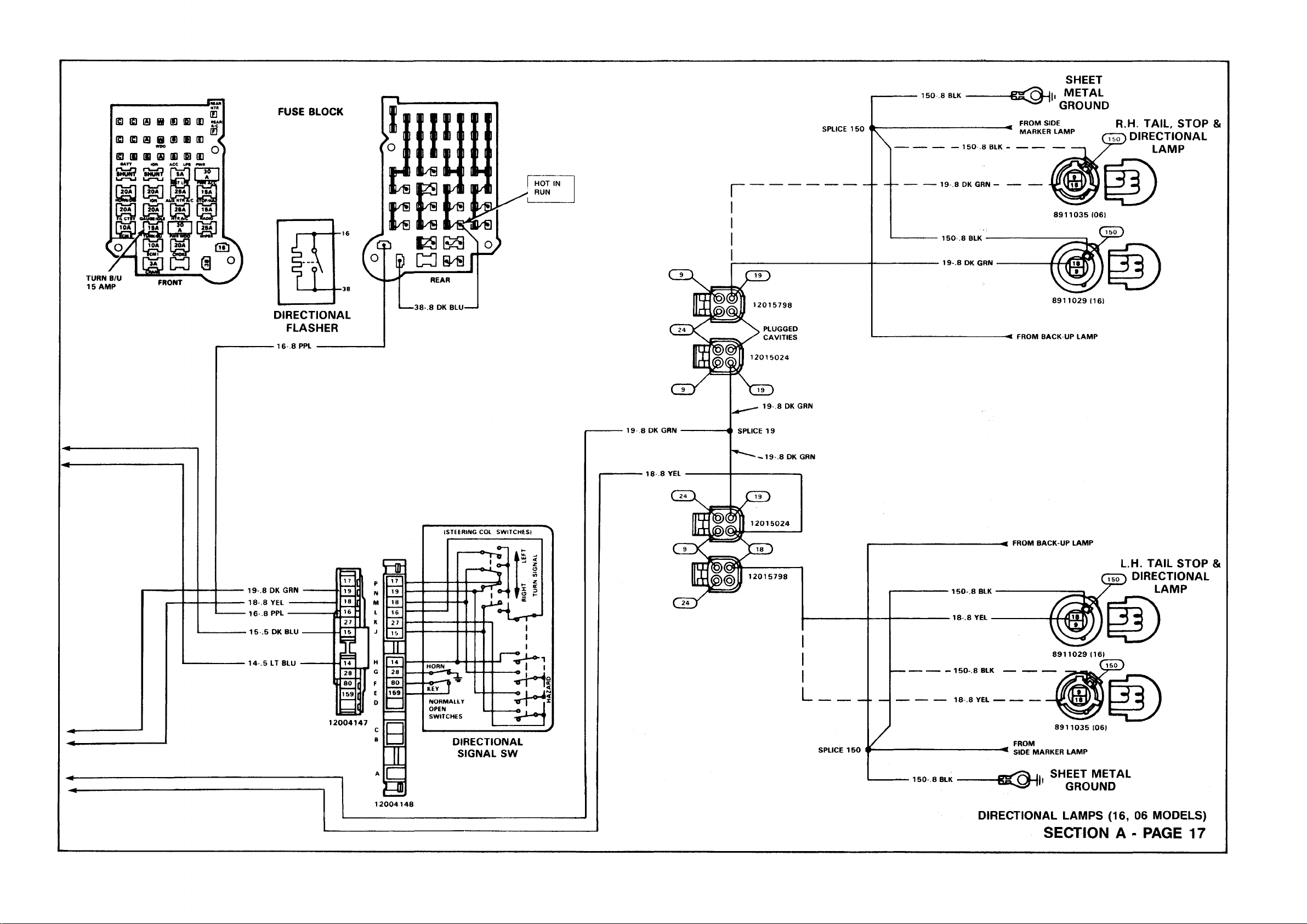
DIRECTIONAL LAMPS (16, 06 MODELS)
L.H. TAIL STOP &
DIRECTIONAL
8911035 (06)
FROM
SIDE MARKER LAMP
SHEET METAL
GROUND
SECTION A - PAGE 17
LAMP
2-2.0 RED THERMO HW
FUSIBLE LINK
2.8 BLK/RED
§1
3 0 z
30 2 <£
| > 3
O m I
C H m
2 m
19 BLK-
O
S
EC
UJ
fs
Q □
S3
o S
8911698
JUNCTION
BLOCK
0 •• ii|
■6-3.0 PPL-
STARTER MOTOR
SOLENOID
-33 .5 TAN/WHT-
d d i o
m p D
Q D f a
B u Q H l
H B n U n
17^—
IS
---
TO PARK
BRAKE
WARNING
SW.
l/P CLUSTER
CONN.
# —2 .8 RED' Q''
SPLICE I
2
r *
5
z
o
s
oc
S i
SPLICE 2
GENERATOR
2-3.0 RED-
12062316
H
Y
M
f s :
3 ( § > sb^ -
t*
2-1.0 RED
FUSIBLE LINK'
2-1.0 RED—
25-1.0 BRN-
•2-1.0 RED-
&
I 2 |440|420|
I 3 9 |806|439|
Il20| I
f
[~4M| 251
[42 2 | 97 |
3 | 3 1 |
1** 1
III
»3 l f
91
Ivw
ill
ENGINE
2 3.0 RED—
SPLICE 2
q d Ue ei
$
o
o
l/P
SPLICE 2
rLivc £
130-.22 BRN/WHT
MANUAL
TRANS
ONLY
I !
TO HD.
LP. SW.
8917548 HEmJ
O <0 «
■ 6 3 0 PPL-
•33- 5 TAN/WHT
CLUTCH ■ ? ; ■
START [ J R
SWITCH T T ^
(MAN. ONLY)
8900371
12010966
------------
AUTO TRANS.
ONLY
GRD 1 Q D j
GRD 2 P T 1
6294641
ST AR1
RUN
OFF
LOCK
ACC
-19 BLK-
«Ol
BATTERY
.8 BLK'
■19 BLK-
SHEET
METAL
GROUND
ENGINE
GROUND
03 0 3 OS H (S ID QD * ■* *
G3 GD ffl H QD 0 3 DD <
IQ BD 0 9 GS OD (0 CD
■ATT ION
r»—£3 o — «~i
SHUNT tHU MT
U—IJ lu—u
r-t_n r*—-n
woo
LM] US
TO
ECM
<0 00
I
I o
n
START GAS (L05, L19)
SECTION A - PA G E 19
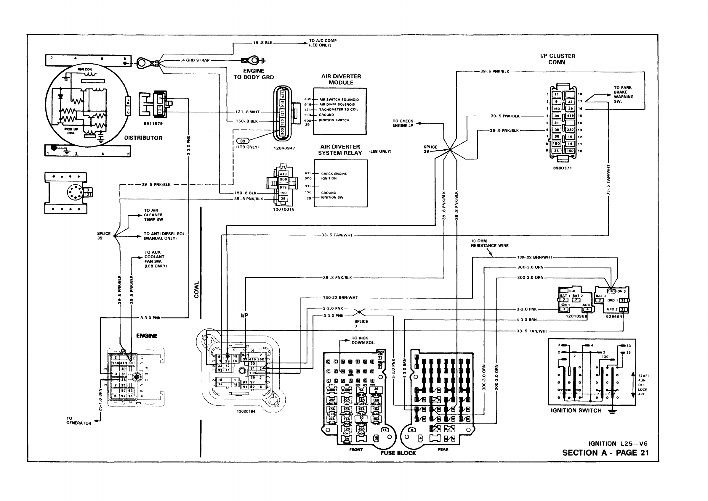
15 .8 BLK
TO A/C COMP
l/P CLUSTER
CONN.
FUSE BLOCK
IGNITION L2 5 -V 6
SECTION A - P A GE 21
ELECTRONIC
CONTROL MODULE
CONNECTORS
9 S I GE N E R ATO R
----
m-
l
I
r
-----
1— p " '♦
I
-----------
Y .
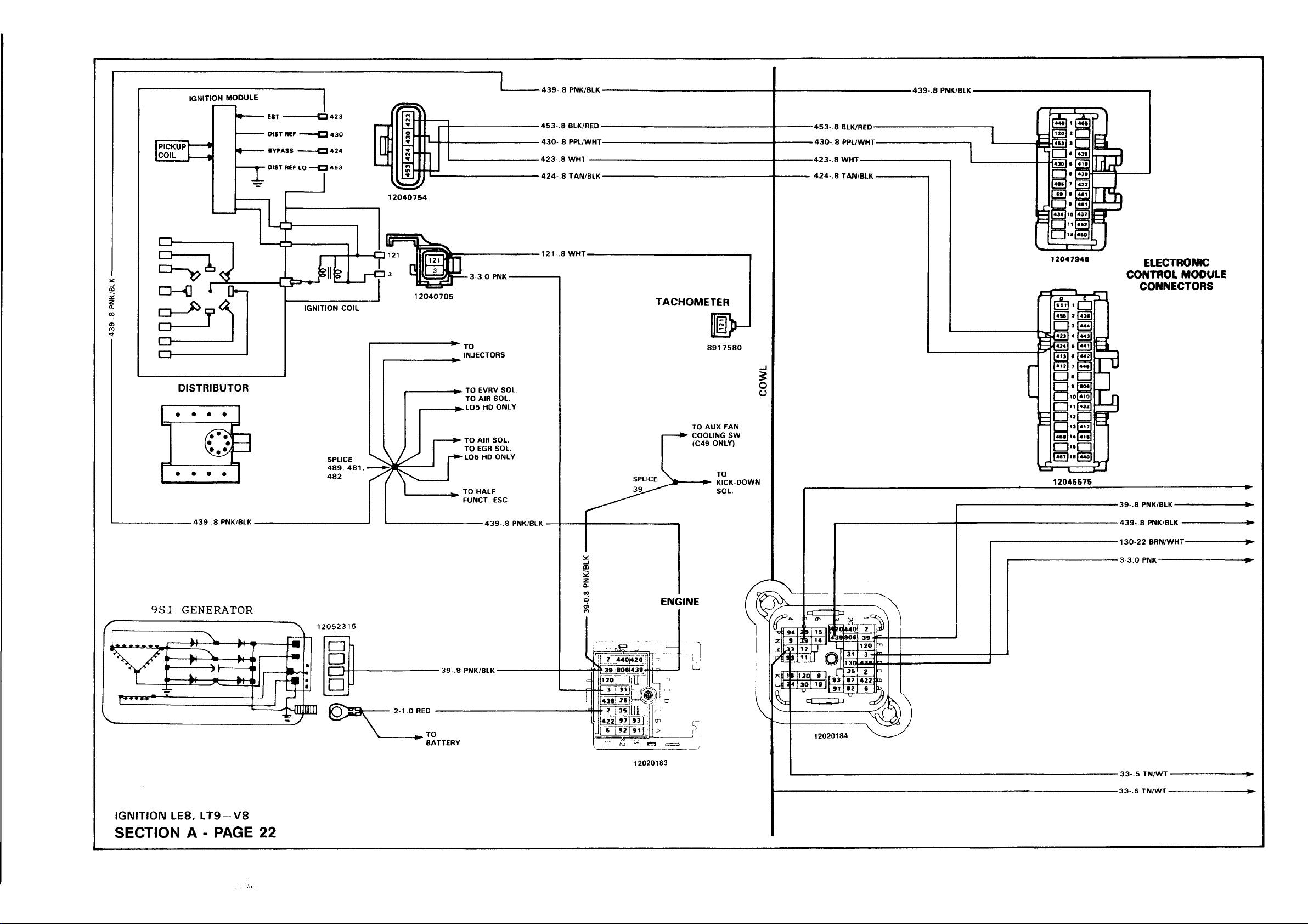
IGNITION LE8, LT 9-V 8
>
-----
h
\ |
-----—|
/F 1
SECTION A - PA GE 22
-j|
m
m
•
m
 Loading...