

Chevrolet P20 (1961), K10 (1961), C20 (1961), K20 (1961), C30 (1961) Operator's Manual
...
1961
TRUC/(
.I
OPERATORS
GUIDE
www.carburetor-manual.com
Would you like some Free Manuals?
http://carburetor-manual.com/free-shop-manual-club-t-13.html
Also visit http://freeshopmanual.com for more Free Manuals
Also Visit my website for 7 FREE Download Manuals starting
with this one.
"The ABC's of Carburetion"
Click Here Now
file:///C|/Documents%20and%20Settings/Tim/Desktop/carburetor-manual-welcome/index.htm[4/25/2009 11:42:20 AM]
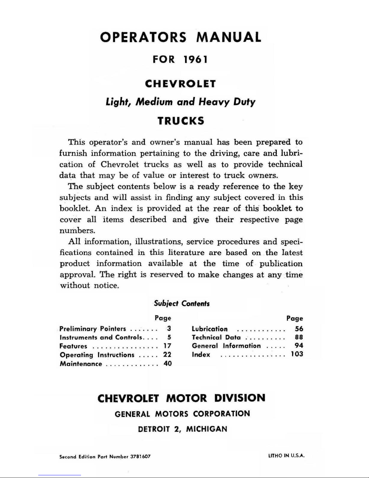
OPERATORS
MANUAL
FOR 1961
CHEVROLET
Light, Medium
and
Heavy
Duty
TRUCKS
This
operator's
and
owne
r's
manual
has
been
prepared to
furnish
information pertaining
to
the
driving,
care
and
lubri-
cation
of
Chevrolet
trucks
as
well
as
to
provide
tec
hni
cal
data
that
may
be
of
value
or
interest
to
truck
owners.
The
subject
contents
below
is a ready
reference
to
the
key
s
ubjects
and
will assist
in
finding
any
subject
covered
in
this
booklet.
An
index
is
provided
at
the
rear
of
this
booklet
to
cover
all
items described
and
give
their
respective
page
numbers.
All
inform
ation, illu strations, service procedures and speci-
fications
containe
d
in
this literature
are
based
on
the
latest
product
information
available
at
the
time
of
publication
approval. The
right
is rese
rved
to
make
changes
at
any
time
without
notice.
Subject Content.
Page
Preliminary Pointe
rs
. . . . . . 3
In struments
and
Controls.
Featur
es
17
Operating
Instructions
22
Maintenance . . . . . . . . . . .
40
Lubrication
Tec
hnic
al
Data
General
Information
Index
CHEVROLET
MOTOR
DIVISION
GENERAL
MOTORS CORPORATION
DETROIT 2,
MICHIGAN
S.cond Edition
Pc"t
Numbe r 3781607
Page
56
88
94
103
LITHO IN U,S.A.
OWNEU'S SEUVICE POLICY
Upon
delivery
of
your
new
Chevrolet
truck,
you
received
an
Owner
Service
Poli
cy
which
you
sho
uld
read
carefully.
Ke
ep this
policy
with your truck
during
the
warranty
period
as
it
serves
to introduce
the
Owner
to
any
Chevrolet
dealer.
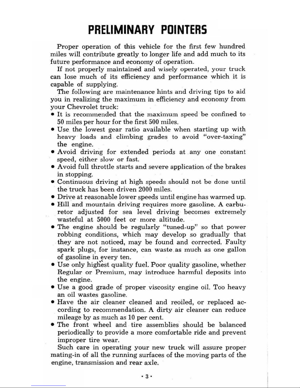
PRELIMINARY
POINTERS
Proper
operation
of
this
vehicle
for
the
first few
hundred
miles
will
contribute
greatly
to
longer
life
and add
much
to
its
future performance and
economy
of
operation.
If
not
properly
maintained
and
wisely operated ,
your
truck
can
lose
much
of
its efficiency and
performance
which
it
is
capable
of
supplying
.
The
following
are
maintenance
hints and
driving
tips
to
aid
you
in
realizing
the
maximum
in efficiency and
economy
from
your
Chevrolet
truck:
•
It
is
recommended
that
the
maximum speed
be
confined
to
50
miles
per hour
for
the
first 500 miles.
•
Use
the
lowest
gear
ratio
available
when
starting
up
with
heavy
loads
and
climbing
grades
to
avoid
"over-taxing"
the
engine.
•
Avoid
driving for
extended
periods
at
anyone
constant
speed,
either
slow
or
fas
t.
• Avoid
full
throttle
starts
and
severe
application
. of
the
brake
s
in
stopping.
•
Continuous
driving
at
high
speeds
should
not
be
done
until
the
truck
has
been
driven
2000 miles.
•
Drive
at reasonable
lower
speeds
until
engine
has
warmed up.
•
Hill
and mountain
driving
requires
more
gasoline. A carbu-
retor adjusted for sea
level
driving be
comes
extremely
wasteful at
5000
feet
or
more
altitude.
•
The
engine
should
be
regularly
"tuned-up" so that
power
robbing
conditions,
which
may
develop
so
gradually
that
they
are
not
noticed,
may
be
found
and
corrected.
Faulty
spark plugs, for instance,
can
waste .as
much
as
one
gall
on
of
gasoline
in
every
ten.
•
Use
only
hign~st
qualit
y fuel.
Poor
quality gasoline,
whether
Regular
or
Premium, may
introduce
harmful
deposits
into
the
engine
.
•
Use
a good
grade
of
proper
viscos
ity
engine
oil.
Too
heavy
an oil
wastes
gasoline.
•
Have
the
air
cleaner
cleaned
and reoiled,
or
replaced ac-
cording to recommendation. A
dirty
air
cleaner
can
reduce
mileage
by
as
much
as
10
per
cent.
•
The
front
wheel
and
tire
assemblies
should
be
balanced
periodically
to
provide a more
comfortable
ride
and
prevent
improper tire wear.
Such
care in
operating
your
new
truck
will
assure
proper
mating-in
of
all
the
running
surfaces
of
the
moving
parts
of
the
engine,
transmission and
rear
axle
.
• 3 •
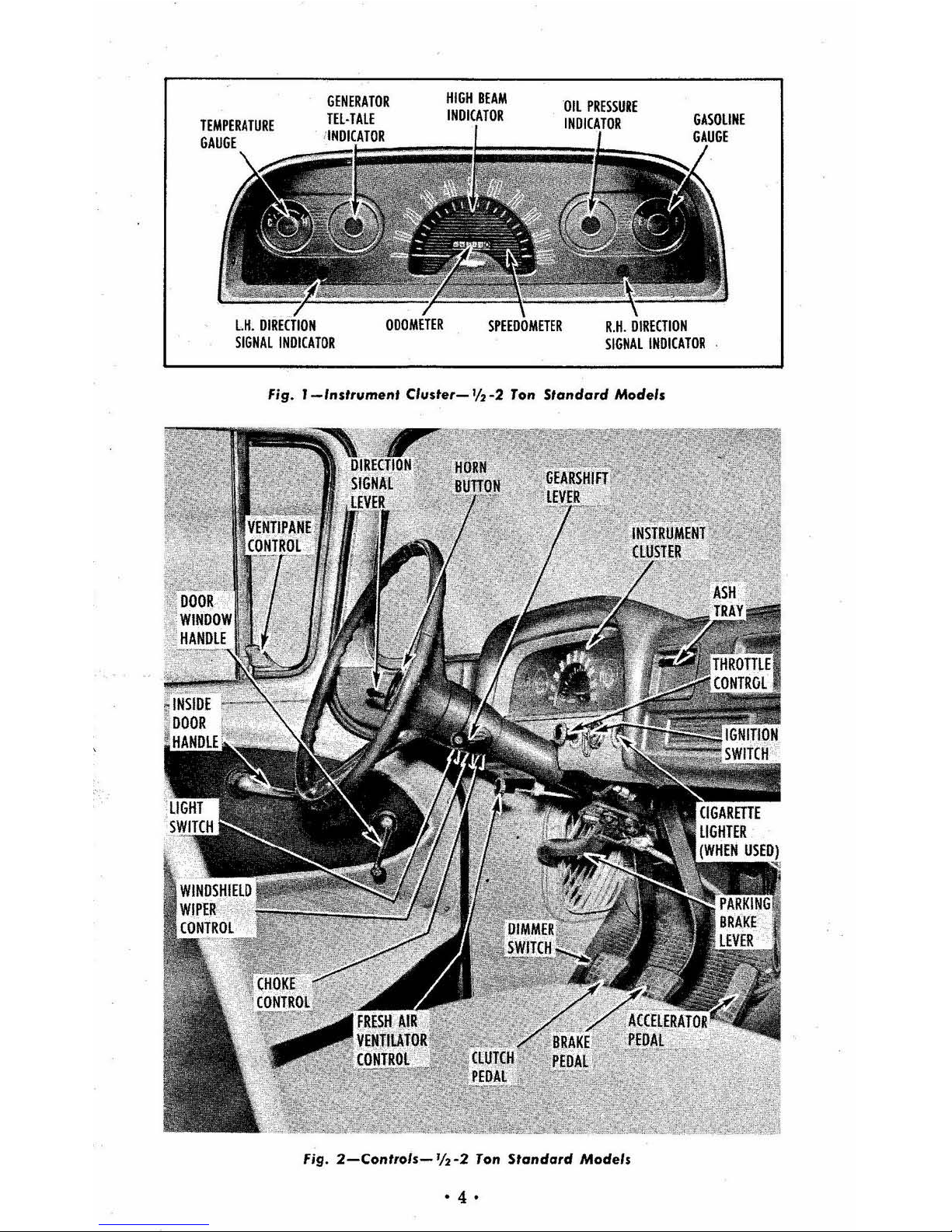
Fig.
I-/ns'rumen,
Cluster-
% -2
Ton
S'andard
Models
Fig.
2-Con,ro/s-'12-2
Ton
Standard
Models
• 4 •
INSTRUMENTS
AND
CONTROLS
The
type, location
and
operation
of
instruments
and
controls
vary
on
different
models
and
different
series
trucks.
There-
fore, regardless of past
experience
an
owner
or driver
may
have
had,
it
is
advisable
to famili
arize
yourself
with
the
instruments and contro ls and their
use
before driving this
new
truck.
As
severa
l different instrument groups and dash
panel assemblies are used,
the
paragraph concerning each
item
will desc
ribe the
operation
or
use
of
that
item
and
will
not
attempt
to
describe
location.
The location
of all
instru-
ments
and controls
will
be
shown
in various illustrations
on
the
following pages.
STANDARD
INSTRUMENTS
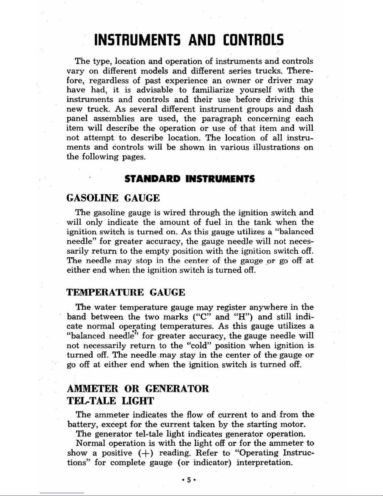
GASOLINE
GAUGE
The
gasoline
gauge
is
wired
through
the
ignition
switch
and
will only
indicate
the
amount
of.
fuel
in
the
tank
when
the
ignition
switch is
turned on.
As
this
gauge
utilizes a "balanced
needle"
for greater accuracy,
the
gauge
needle
will
not
neces-
sari
ly
return
to
the
empty
position
with
the
ignition
switch
off.
The
needle
may
stop in
the
center
of
the
gauge
.or go off
at
either
end
when
the
ignition switch is
turned
off.
TEMPERATURE
GAUGE
The
water
temperature
gauge
may
register
anyw
here
in
the
band
between
the
two
marks
("C" and
"H")
and
still indi-
cate normal operating temperatures.
As
this gauge utilizes a
"balanced
needle~'
for greater accuracy,
the
gauge
needle
will
not
necessarily return to
the
"cold" position
when
ignition is
turned
off.
The needle ,may
stay
in
the
center
of
the
gauge
or
go off
at
either
end
when
the
ignition switch is
turned
off.
AMMETER
OR
GENERATOR
TEL-TALE
LIGHT
The
ammeter
indicates
the
flow of
curren
t to
and· from
the
battery,
except
for
the
current
taken
by
the
sta
rting
motor
.
The
generator
tel-tale
light
indicates
generator
operation.
Normal
operation
is
with
the
light
off
or
for
the
ammeter
to
show
a positive
(+)
reading.
Refer
to
"Operating Instruc-
tions" for complete
gauge
(or
indicator) interpretation.
·5·
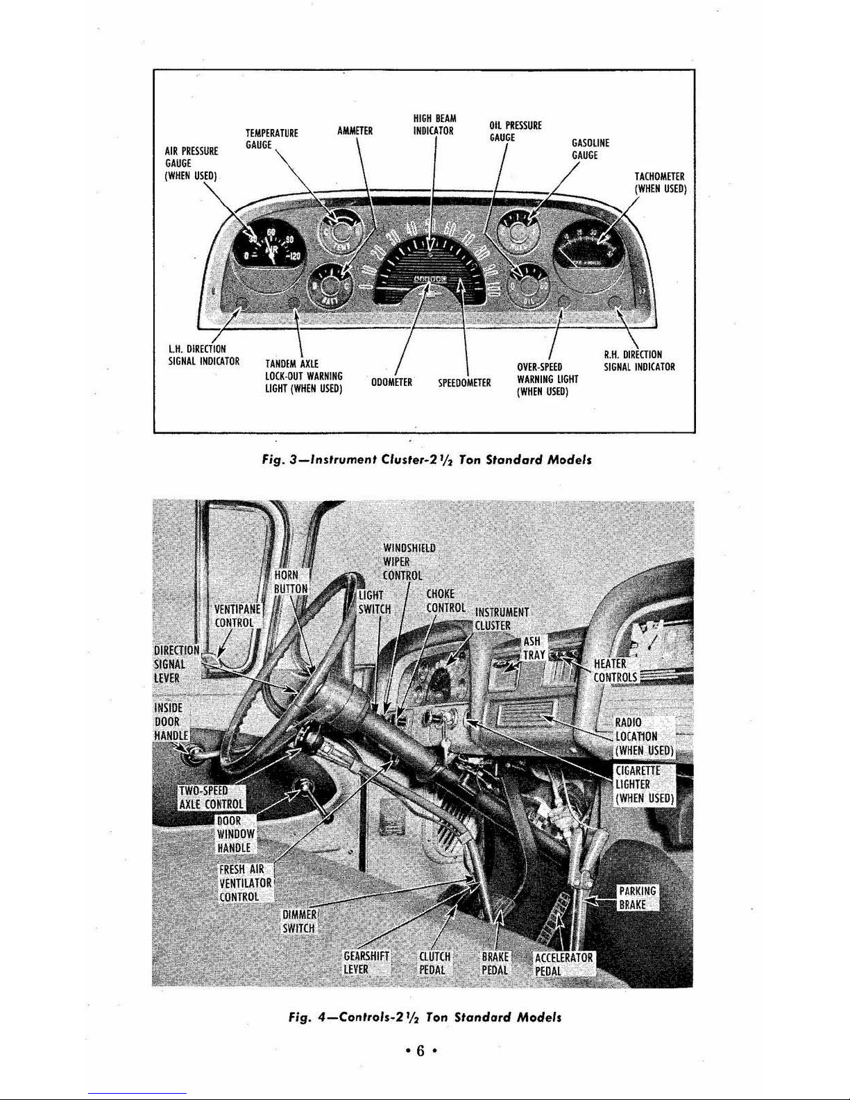
Fig.
3_lnslrumen'
(Iusf.,·2
'12
Ton
Standard
Models
Fig.
4-(on',oh.2'12
Ton
Standard
Modell
·6
•
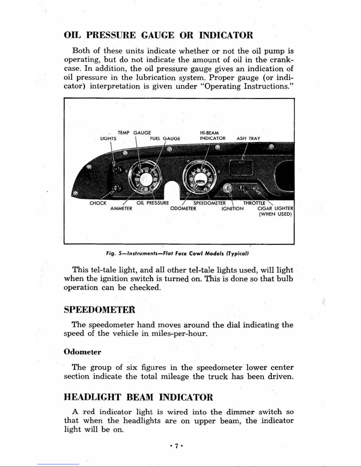
OIL PRESSURE
GAUGE
OR INDICATOR
Both
of
the
se units indica
te
whether
or
not
the
oil
pump
is
operating,
but
do
not
indicate
the
amount
of
oil
in
the
crank-
case. In addition,
the
oil pr
ess
ure
gauge
giv
es
an
indication
of
oil
pressure
in the lubri cat
ion
system. Proper
gauge
(or indi-
cator) int erpretation is giv
en
under
"Op
era
ting
Instructions,"
Fig .
5-lnstrum.nls-FIG'
Fac.
Cowl
Mod.,s
(Typico"
This tel-tale
light, and all
other
tel-tale
lights use d, will lig
ht
when
the
ignition switch is
turned
on.
Thi
s is d
one
so
that
bulb
op
eration
can
be
checked.
SPEEDOMETER
Th
e spee
domet
er ha
nd moves
around
the
dial
indicating
the
speed
of
the vehicle
in
miles-per-hour.
Odometer
The group
of
six
figur
es
in
the speedometer
lower
cent
er
secti
on
indicate the
tot
al mileage
the
truck has
been
driv
en.
HEADLIGHT
BEAM
INDICATOR
A red
indicator
light
is
wired into
the
dimmer
switch
so
th
at
when the headlights
are
on
upper beam,
the
indicator
li
ght
will
be
on.
·7·
OVER
SPEED
WARNING LIGHT
As
standard
equipment
on
seve
ral
larger
series
trucks
and
optional
equipment
on
certain others, a
red
light
warns
of
ex-
cessive
engine
speed on
overrun
on
VB
engines. As a
check
to
be
cert
ain
that
the
bu
lb
works,
this light
is
so
wired
that
it
turns on at
the
instant the ignition switch is turned on and
go
es off
after
the
engine has
started.
OPTIONAL INSTRUMENTS
AIR PRESSURE. GAUGE
This
gauge
is used
to
indicate
the
air
pressure
in
the
full
air
brake
system
or
the air
over
hydraulic
system.
Do
not
--a
ttempt
to
oper
ate
the vehicle
unle
ss
pressure
has
built
up
to
60 p
si
or
more.
Low
Pressure Indicator
A warning buzze
r,
mount
ed
und
er
the
dash
operates
when
air
pressure
in the bra
ke
system falls below
60
psi.
When
first
starting
the
vehicl
e,
the warn
ing buzzer will sound
until
pres-
sure has
built up.
Wh
en
the
desired
pressure has
been reached,
the
buz
zer
will s
hut
off.
If
the
buzzer oper
ates
under
normal
drivin
g,
bring
the vehicle to a contr
oll ed
stop
and
locate and
correct trouble
before
proceeding.
NOTE: Do not operate vehicle w hile buzz
er
is
operating as brakes
are not in
proper
operat-
ing condition.
TACHOMETER
Th
e tacho
meter
(when
installed)
indicates engine speed in
revolutions per
minute.
The sca
le reads
10, 20, 30, etc. By
add-
ing
two
zeroes
after
the
reading,
the
indicat
ed
engine spee
d
will become
1000 , 2000, 3000, etc.
Transmission shifting
range
is
indi
cated by two markers factory set at 25 & 40, w
hich
can
be
a
djustin
g a
long
the
periph
ery
of
the gage
to
indicate
the
opti
-
mum
range for
any
particular vehicle.
VACUUM GAUGE
This gauge
(when
installed)
indicates
engine vac
uum.
Proper
interpretation
of
the
gauge
readings
will
indicate engine con-
dition , and
in
many
instan
ces show
the
way
to
more
economi-
cal operation.
• 8 •
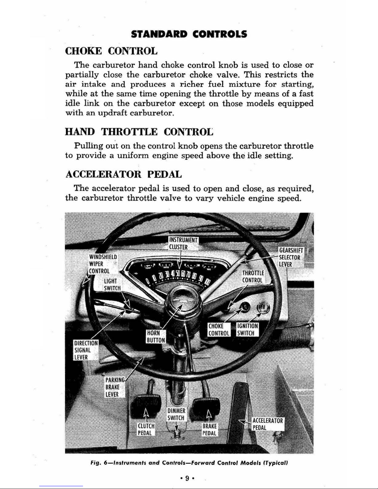
STANDARD CONTROLS
CHOKE CONTROL
The
carburetor
hand
choke
control
knob
is
used
to
close
or
partially
close
the
carburetor
choke
valve.
This
restricts
the
air
intake
and
produces a richer
fuel
mixture
for
starting,
while
at
the
same
time
opening
the
throttle by
means
of a fast
idle
link
on
the
carburetor
except
on
those models
equipped
with
an
updraft
carburetor.
HAND THROTTLE CONTROL
Pulling
out
on the
control
knob
opens
the
carburetor
throttle
to provide a
uniform
engine
speed
above
the
idle setting.
ACCELERATOR PEDAL
The
accelerator
pedal
is
used
to
open
and
close, as
required
,
the
carburetor
throttle
valve
to
vary
vehicle engine speed.
fig.
6-lnsfrumenh
Gnd
Controls-Forward
Conrrol Models (TyplcalJ
•
9'
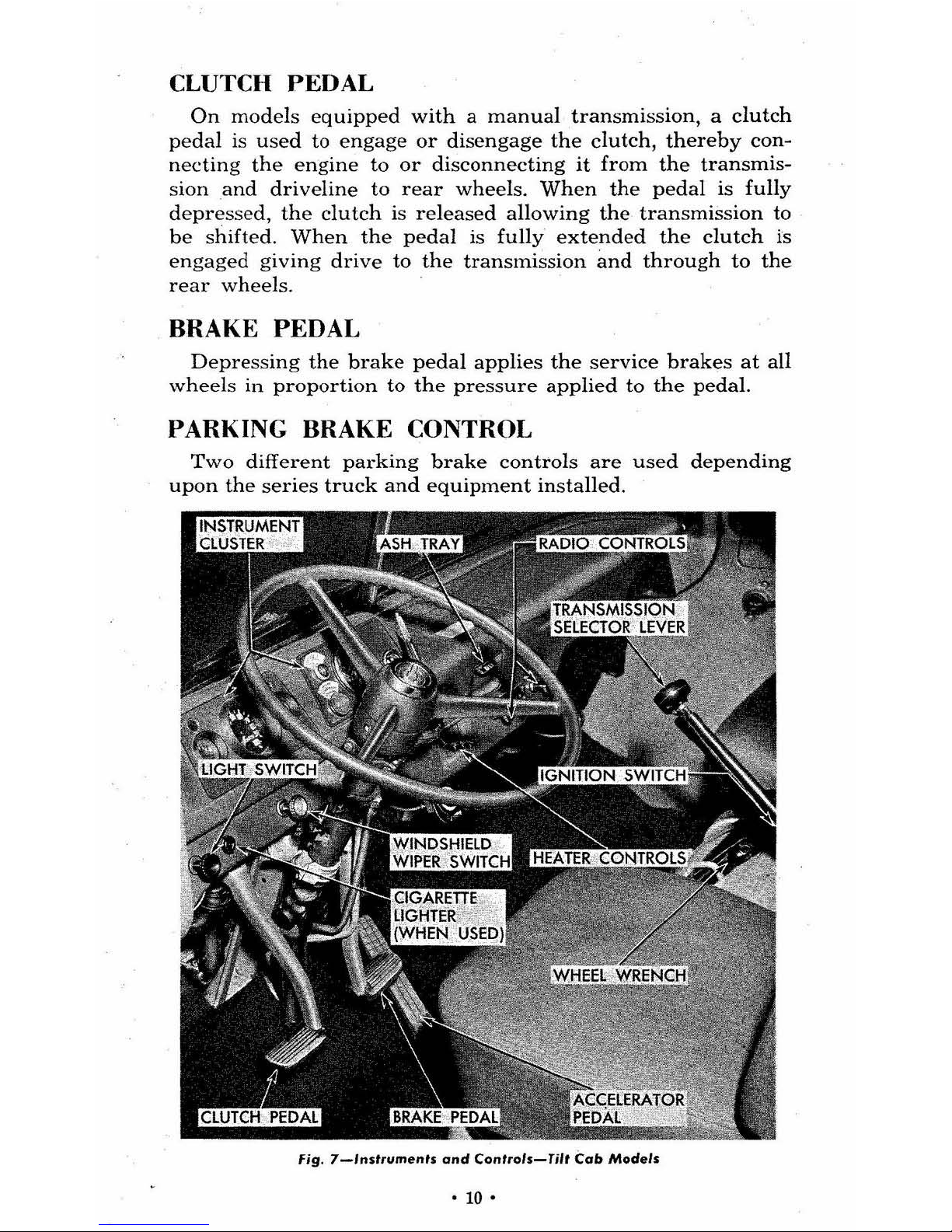
CLUTCH PEDAL
On
models
equipped
with a manual
transmission , a
clutch
pedal
is
used
to
engage
or
disengage
the
clutch,
thereby
con-
necting
the
engine
to
or
disconnecting
it from
the
transmis-
sion
and
driveline
to
rear
wheels.
When
the
pedal
is
fully
depressed,
the
clutch
is re
leased
allowing
the
transmission to
be
shifted.
When
the
pedal
is
fully
extended
the clutch
is
engaged giving
drive
to
the
transmission
and
through
to
the
re
ar
wheels.
BRAKE PEDAL
Depressing the
brake
pedal
applies
the
service
brakes
at
all
wheels
in
proportion
to
the
pressure
applied
to
the
pedal.
PARKING BRAKE CONTROL
Two
different
parking
brake
controls
are
used
depending
upon
the
series
truck
and
equipment
installed.
Fig.
7_lns'rumen's
and
Controls-Til,
Cab Models
.
10·
On
one
line
of trucks, a contr
ol l
ever exte
nding up from the
cen
ter section
of the fro
nt floor is used. By pulling st
raig
ht
back on
the lev
er, the pa
rking
brak
es
are
applied. To release
the bra
kes, s
queez.e the mova
ble
lever at the top of the contro
l
a
nd
at the same
time, push
forward.
CAUTION :
On
models
equipped
wifh
auxiliary
transmission, au
xilia ry transmission
must
be
in
gear
before applying
parking
brak
e.
The oth
er one used, is a trigger type l
eve
r mount
ed
to the
left of
the stee
ring co
lumn
und
er the instrument
panel.
To
a
pp
ly the brakes, pull back
on the l
eve
r. To release, squeeze
the "pistol
" ty
pe
tri
gger a
nd push forwa
rd.
GEA
HSHIFT LEVER
The gearshift contr
ol on
tru
cks e
quip
ped
wit
h 3-speed trans-
mi
ss
ion is loc
ated
on the s
teering column.
Thi
s co
ntr
ol is used
in the conve
ntional
HH" p
atte
rn
as explain
ed und
er "Operat-
in
g Instruction
s"
to sh
ift
the
tran
smissi
on
to the desir
ed ratio.
Th
e g
earshift
contro
l for vehicl
es with the 4- or 5-
spee
d
tr
ansmissio n is lo
cat
ed
in
the
center
sec
tion
of
the front floor
except
tilt
cab models
whi
ch
is locate
d betwee
n the fro
nt
seats
. The shifting
pattern
for
ea
ch transmission is shown on
top
of the con
tro
l lever knob.
S
ee HOperating
Ins
tru
cti
ons"
for t
he
spec
ific tran
smission
u
sed
.
Th
e c
ontro
l lev
er
for
vehi
-
cles equipped with
four
wheel
drive is m
oun
ted
next
to the
trans
mi
ssion c
ontrol lever.
This
control is used
to sel
ect
fig.
8-I
gn;,;on Switch fS·
'ar'
. r Cont
rol}
the diff
ere
nt
axle drives
.
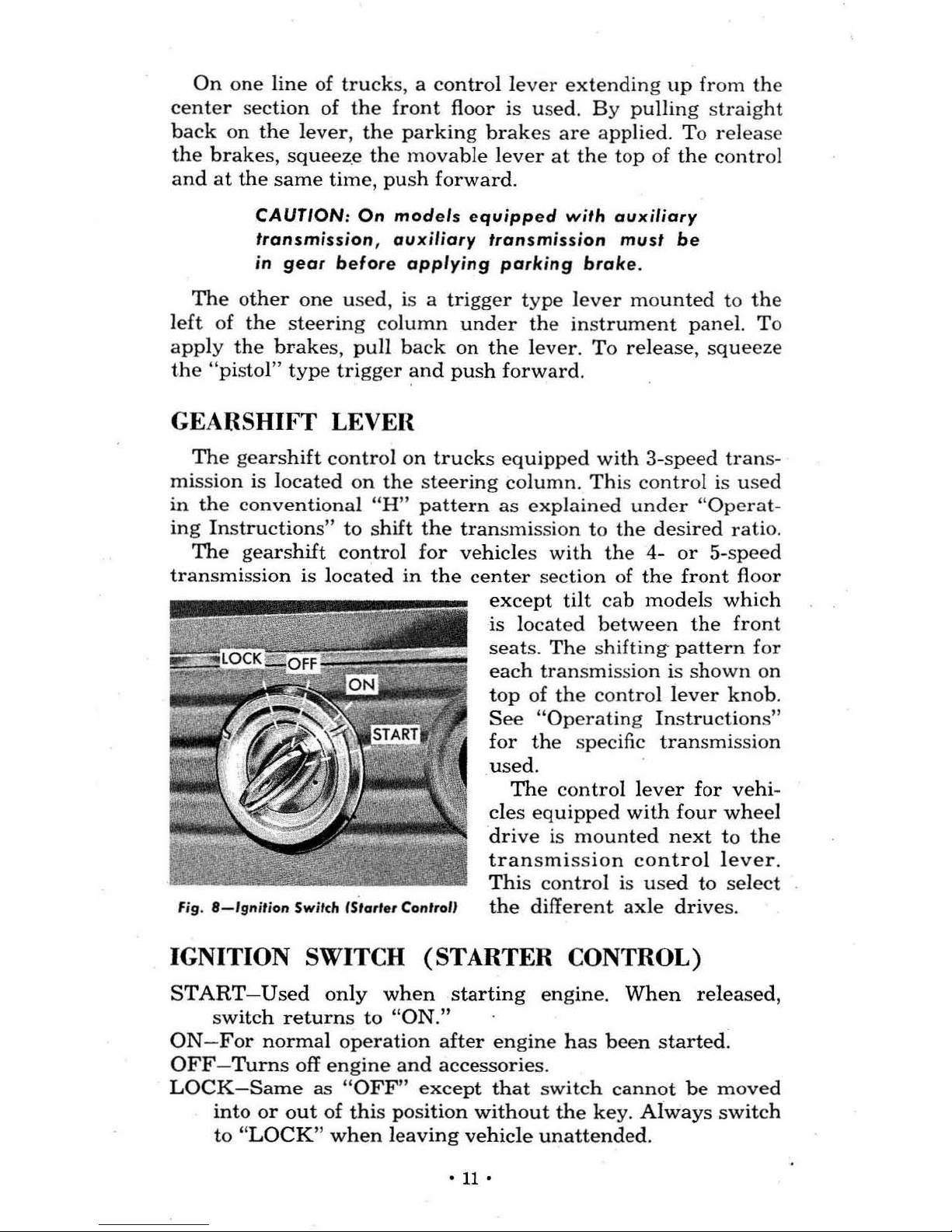
IGNITION S
WIT
CH (STARTER CONTROL)
ST
ART-Used
on
ly
when
starting
eng
ine. Wh
en
released
,
s
witch return
s to
"ON
."
ON
- For nor
ma
l operati
on
aft
er engine h
as bee
n s
tarted
.
OFF
- T
urn
s off engine and acc
ess
ori
es.
L
OCK-Same
as HOFF" except
that
switch cannot be moved
i
nto or out of
this position
without the k
ey. Always switch
to
"L
OCK" when lea
ving veh
icle
unattend
ed .
•
11
•
NOTE
: Key
cannot
be
removed from the
igni-
tion switch
when
in
"OFF" position thus
guarding
against
accidentally
leaving
switch
off
but
not
locked
. Key
must
be
removed
when
the switch is
in
"LOCK"
or "ON"
pos
i-
tion. The switch
may
then
be
moved
be-
tween
"OFF"
and
"ON" without the key .
WINDSHIELD WIPER SWITCH
Start
wiper
by
turning
knob
clockwise.
Full
counter
clock-
wise
position turns wiper off.
The
electric wiper
has
two posi-
tions-OFF
and
ON.
When
the
wipers
are
turned
off,
they
will
return
to
the
inner
end
of
the
wiper
cycle.
CAUTION:
In
icy
weather,
never
attempt
to
ope~ate
electric
wipers
if
blades
are frozen
to
the
windsh
ield. Free
the
blades
before
operation
01
wipers
.
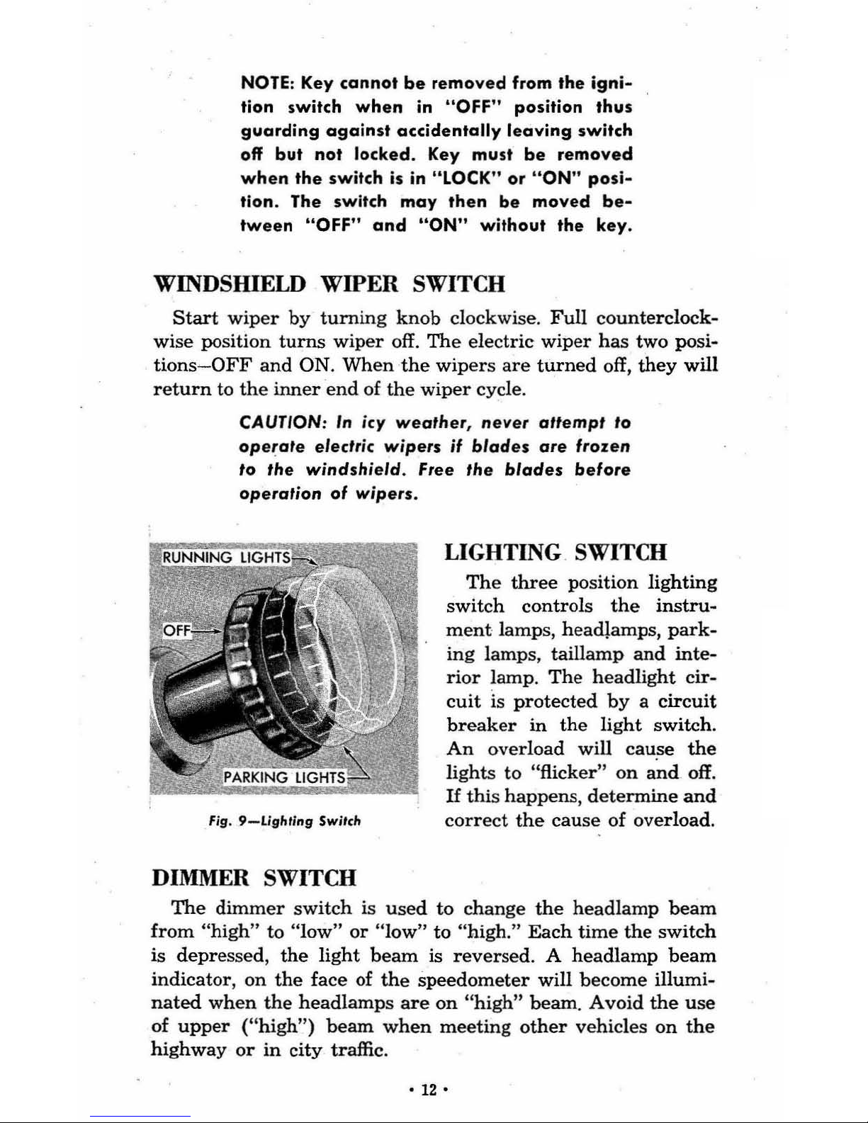
Fig.
9-Lighring
Switch
DIMMER SWITCH
LIGHTING SWITCH
The
three
position lighting
switch controls
the
instru-
ment
lamps, headlamps,
park-
ing lamps , taillamp
and
inte-
rior
lamp.
Th
e headlight cir-
cuit
is
protected
by
a circuit
br
eaker
in the
light
switch.
An
overload will cause
the
lights
to
"flicker"
on
and
off.
If
this happens, determine
and
correct
the
cause
of
over
load.
The
dimmer
switch
is
used
to change
the
headlamp
beam
from "high" to "low" or "low" to "high." Each
time
the
switch
is depressed,
the
light
beam
is reversed. A
headlamp
beam
indicator,
on
the
face of
the
speedometer
will become illumi-
nated
when
the
headl
amps
are
on
"high"
beam. Avoid
the
use
of
upper
("high")
beam
when
meeting
other
vehicles on
the
highway
or
in
city
traffic.
•
12·
HORN BUTTON
The
horn
butt
on
is
conveniently
located at
the
center
of
the
steering
wheel.
Depressing
this
button
gro
unds
out
the
horn
circuit
causing
the
horns
to operate.
COWL
VENTILATOR CONTROL KNOBS
Two knobs
are used
to
open
and
close
the
dampers
in
the
vent
ilati
ng
system.
Pull
knob(s)
out
to a
dmit
outside
air,
push
knob(s)
in
to s
hut
off
air.
WINDOW REGULATORS AND HANDLES
The door
windows
are
opened
and
closed
by
turning
the
handles from
within
the
vehicle.
DOOR VENTIPANE AND HANDLES
The
se
are
operated
directly
by a turn down
catch
handle
. A
spring
loaded
friction device
in
the
ventilator
lower
pivot
holds
the
ventilator
open
to
any
position selected.
Rain
deflectors
are used over
the
ventipane
to
prevent
ent
ry
of
water.
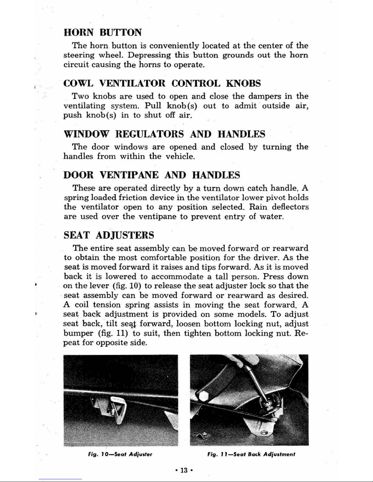
SEAT ADJUSTERS
The
entire
seat
assembly
can
be
moved
forward
or
rearward
to
obtain
the
most
comfortable
position
for
the
driv
er.
As
the
seat
is
moved
forward
it
raises
and tips forward.
As
it is
moved
back it is
lowered
to
accommodate a tall
person.
Press down
on the
lever
(fig. 10) to
relea
se
the
seat
adjuster
lock so
that
the
seat
ass
embly
can
be
moved
forward
or rearward as desired.
A coil
tension
spring
assists in m
oving
the seat forward. A
seat
back
adjustment
is
provided
on
some
models.
To
adjust
seat
back, tilt
se'lt
forward,
loo
sen
bottom
locking
nut, adjust
bumper
(fig. 11)
to
suit,
then
tighten
bott
om
locking
nut.
Re-
peat
for
opposite s
ide
.
Fig
. r
O-Seat
Ad;ust.r Fig. J
I-SuI
Back Ad;ustment
·13·
HOOD
LOCK
AND SAFETY CATCH
The
hood is of
the
"alligator
jaw"
type
and
is
held
closed
by
a lock
at
the
front.
This lock
can
be
released
by
reaching
in
above
the
upp
er
gri
lle
bar
in
line
with
the
right
end
of
emblem
and
pulling
the lever
forward
(fig. 12),
the
hood
may
then
be
lifted.
To
close
the
hood,
l
ower
it
from
a
completely
open
position with a firm
downward
movement
to
lock
it.
When
the
truck
is
in
motion,
the
cam
type
lock
Fig.
12-Hood
Lock
permits
only
downward
movement
of
the
hood
with
a
wedging
adtion
that
provides
positive
lock
ing.
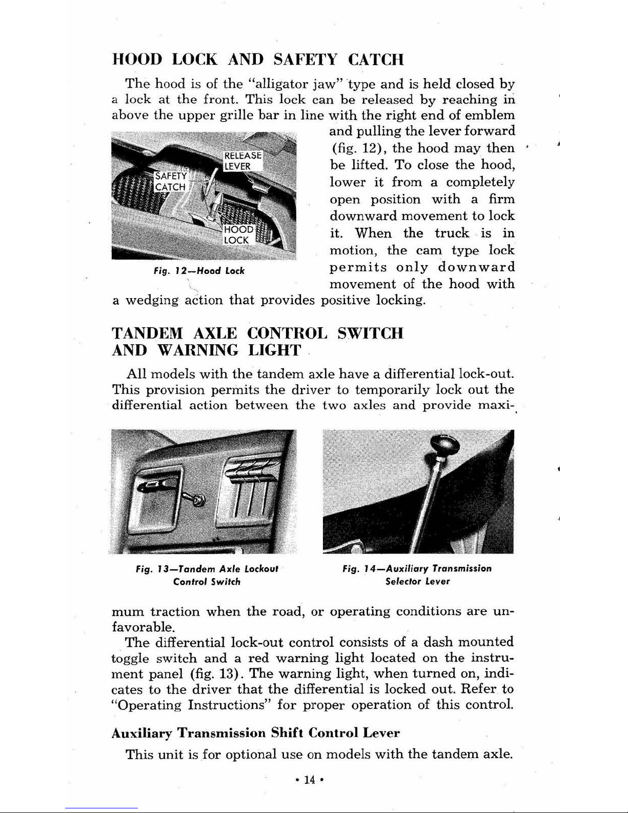
TANDEM AXLE CONTROL SWITCH
AND WARNING LIGHT
All
models
with
the
tandem axle
have a differential lock-out.
This
provision
permits
the
driv
er
to
temporarily
lock
out
the
differential
action betw
een
the
two
axles
and
provide
maxi-,
Fig.
l3-Tandem
Axle
Lockout
Control Switch
Fig .
14-Auxiljory
Transmission
Selector Lever
mum
traction
when
the
road, or
operating
conditions
are
un-
favorable.
The
differential
lock-out
control
consists
of a
dash
mounted
toggle
switch
and a red
warning
light
located
on
the
instru-
ment
panel
(fig. 13).
The
warning
light,
when
turned
on,
indi-
cates
to
the
driver
that
the
differential
is locked
out.
Refer
to
"Operating
Instructions"
for
proper
operation
of
this
control.
Auxiliary
Transnlission
Shift
Control Lever
This unit
is
for
optional
use
on
models
with
the
tandem
axle
.
•
14
•
The
control for
this
unit
is
mounted
between
the
two
front
seats
(fig. 14).
The shift
pattern
is
shown
on
the
control
lever
knob.
OPTIONAL CONTROLS
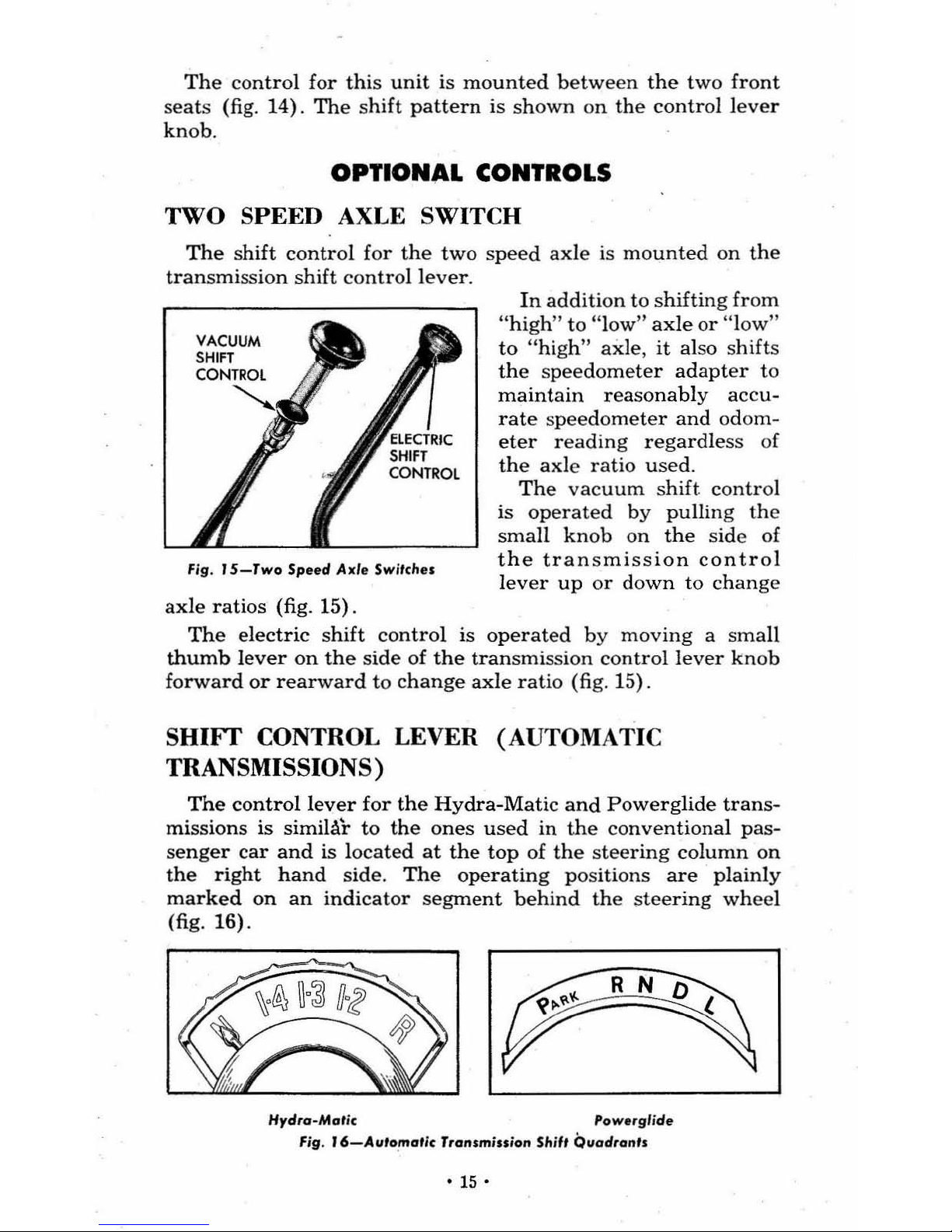
TWO SPEED AXLE SWITCH
The
shift
control
for
the
two
speed
axle
is
mounted
on
the
transmission shift
control
lever.
Fig.
15-Two
Speed Axle Swi'che,
axle
ratios
(fig.
15).
In
addition
to
shifting
from
"high" to "low"
axle
or
"low"
to
"
high
'!
axle, it also shifts
the
spee
dometer
adapter
to
maintain reasonably accu-
rate
spee
dometer and odom-
eter
reading
regardle
ss
of
the
axle
ratio used.
The
vacuum shift
control
is
operated
by
pulling
the
small
knob
on
the
side
of
the
transmission
control
lever
up
or
down
to
change
The
electric
shift
control
is
operated
by
moving
a
small
thumb
lever
on
the
side
of
the
transmission control
lever
knob
forward
or
rearward
to
change
axle
ratio
(fig. 15).
SHIFT CONTROL LEVER (AUTOMATIC
TRANSMISSIONS)
The
control
lever
for
the
Hydra-Matic
and
Powerglide
trans-
missions
is
simiI.fr to
the
ones
used
in
the conventional
pas-
senger
car
and
is
located
at
the
top
of
the
steering
column
on
the
right
hand
side. The operating
positions
are
plainly
marked
on
an
indicator
segment
behind
the
stee
ring
wheel
(fig. 16).
Hydro-MCJtic
Powe,glide
Fig
.
16-Auto
.maf;c Tronsmission Shiff Quodranls
•
15
•
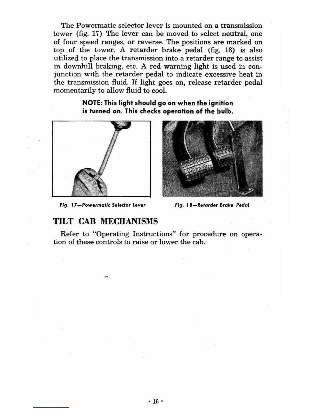
The
Powermatic selector lever
is
mounted
on a transmission
tower
(fig. 17)
The
lever
can
be
moved
to select
neutral, one
of
four
speed
ranges
, or
reverse. The positions
are
marked
on
t
op
of the tower. A
retarder
brake
pedal
(fig. 18)
is
also
utili
zed to
place
the
transmission
int
o a
retarder
range
to
assist
in
downhill
braking
, etc. A
red
warning
light
is
used
in
con-
iu
nction
with
the
retarder
pedal
to indicate excessive
heat
in
the transmission
fluid.
If
light
goes on,
release
retarder
pedal
momentarily
to
allow fluid
to
cool.
NOTE:
This
light should go on
when
the ignition
is
turned
on
.
This
checks operation
of
the bulb.
Fig. J
7-Powermoric
$eleclor lever F
ig. J a-Re'arder
Bralce Pedal
TILT
CAB
MECHANISMS
R
efer
to
"Operating
Instructions"
for
procedure
on opera
-
tion of
these
controls
to rai
se
or lower the cab.
·
16·
FEATURES
STANDARD EQUIPMENT
ASH
TRAY
A
convenient
tilt
type
ash
tray
is located
in
the
center
area
of
the
instrument
panel.
The
tray
is
opened
by
pushing
it
for-
ward
at
the
bottom
and
pulling
it
out
at
top. To
remove
the
ash
tray
for
emptying, depress
the
circular
snuffer
at
top
of
tray
and
pull
out. To
replace
, h
ook
the
lower
inner
edge
of
tray
over
retaining rod, and
push
in at top.
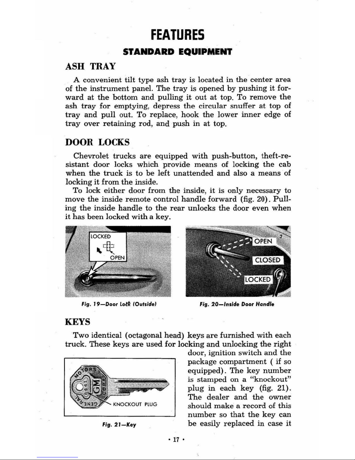
DOOR LOCKS
Chevrolet
trucks
are
equipped
with
push-button,
theft-re-
sistant
door
locks
which
provide
means
of
locking
the
cab
when
the
truck
is
to
be
left
unattended
and
also a
means
of
locking
it
from
the
inside.
To lock
either
door from
the
inside, it
is
only
necessary to
move
the
inside
remote
control
handle
forward
(fig. 20).
Pull-
ing
the
inside
handle
to
the
rear
unlocks
the
door
even
when
it
has
been
lock
ed
with
a key.
Fig
.
19-000'
LolA
lOuts/d.'
Fig.
20-lnslde
Door Handl.
KEYS
Two
identical (octagonal
head)
keys
are
furnished
with
each
truck.
These
keys
are
used
for
locking
and
unlocking
the
right
door, ignition switch and the
package
compartment
( if so
equipped). The
key
number
is
stamped
on
a "knockout"
plug
in
each
key
(fig. 21).
The
dealer
and
the
owner
should
make a record
of
this
number
so
that
the
key
can
Fig.21-K
ey
be
easily replaced in case
it
•
17
•
is l
ost, and
the
"knock
out"
plug should
be
removed
so that
unauthorized
persons cann
ot
obtain
the
key
number
and have
a
duplicate
made.
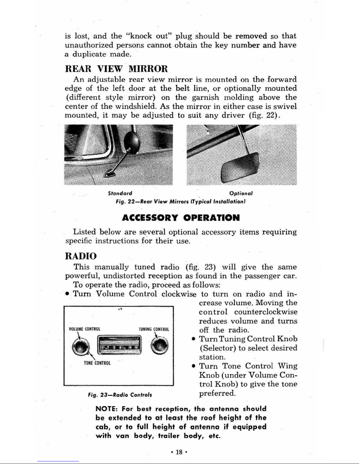
REAR VIEW MIRROR
An adjustable
rear
view mirr
or
is
mounted
on
the
forward
edge
of
the
left
door
at
the
belt line,
or
optiona
lly
mounted
(different
sty
le
mirror)
on
the
garnish
mo
lding
above
the
center
of
the wind
shield.
As
the
mirror
in
either
case
is swivel
mounted,
it
may
be
adjusted
to
suit
any
driver
(fig.
22).
Standard
Op
tion al
fig
.
22-II
.or
V
iew
Mirrors (Typical
'nstallot;on'
ACCESSORY OPERATION
Listed
below
are
severa
l o
ptional
accesso
ry
items
requirin
g
specific
instructions
for
their
use.
RADIO
This manually
tuned
radi
o (fig. 23) will
give
the
same
powerful,
unrli
storted
reception
as
found
in
the
passenger
car.
To
opera
te
the
radio,
proceed
as
follows:
•
Turn
Volume
Control
clockwise
to
turn
on
radio
and
in-
crease volum
e.
Moving the
contro
l
coun
tercl
ockwise
reduces volu
me
and
turns
'.;'
.,.
f'i
TONECOIiTROl
Fig .
23-lladio
Con trols
off
the
radio.
•
Turn Tuning
Control
Knob
(Selector)
to select
desired
station.
•
Turn
Tone
Control
Wing
Knob
(under
Volume Con
-
trol
Knob)
to
give
the
tone
preferred.
NOTE: For
best
reception,
the
antenna
should
be
extended
to
at
least
the
roof
height
of
the
cab, or
to full
height
of
antenna
if
equipped
with
van
body,
trailer
body,
etc .
• 18 •
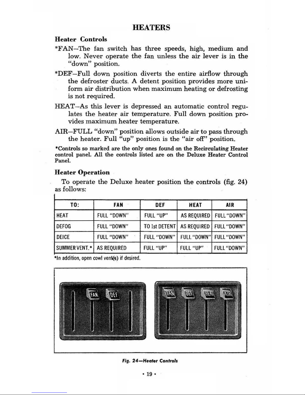
HEATERS
Heater
Con
trol
s
"
FAN
-The
fan
sw
itch
has
three
speeds, high,
medium
and
low.
Never
operate
the
fan
unless the
air
lever
is
in
the
"down" position.
"
DEF -Full
down
position
diverts the
entire
airflow
through
the
defroster
duct
s. A
detent
position provides
more
uni-
fonn
air distributi
on
when
maximum
heating or defrosting
is
not
required.
HEAT-As
this lever
is de
pre
ssed
an
automatic
control regu-
lates
the
heat
er
air
temperature.
Full
down
pos
ition
pro-
vides
maximum
heater temperature.
AIR-FULL
"down" pos ition allows
outside air to pass through
the
heater.
Full
"up" position is
the
"air off" position.
·Controls so marked are the only ones found on the Recirculating Heater
control paneL
All
the controls listed are on the
Deluxe
Heater Control
Pane
l.
Heater
Operation
To
operate
the
Del
uxe hea
ter
position
the
controls (fig. 24)
as
follows:
TO
:
FAN
OEF
HEAT
AIR
HEAT
FUll
"DOWN"
FUll "UP"
AS REQU
IRE
D
FUll "
DOWN
"
DEfOG
FUl
l "
DOWN"
TO
1st
DETENT
AS
REQUIRED
FUll "DDWN"
DEICE
FUll
"DOWN
" FUll "
DOWN
"
FUll
"DOW
N"
FUll
"DOWN"
SUMM
ER
VENT
.•
AS
REQUIRED
FUll
"UP"
FULL "UP"
FULL
"DOWN"
·'n
addi
tion, open
cowl
vent(ti)
If
desired.
Fig.
24-H.aler-
Can'r-als
·
19·
To
Operate
the
Recirculating
Heater
position
the
controls
(fig. 24) as follows:
TO:
FAN
DEF
HEAT
AS
REQUIRED
FUll
"UP"
DEFOG
FUll "
DOWN
"
TO
FI
RST
DETENT
DEICE
FUll "
DOWN"
FUll
"DOWN"
SUMMER
VENT'
AS
REQUIRED
FUll
"UP"
·In
addition,
open
cowl
vent(s)
if
desi
red
.
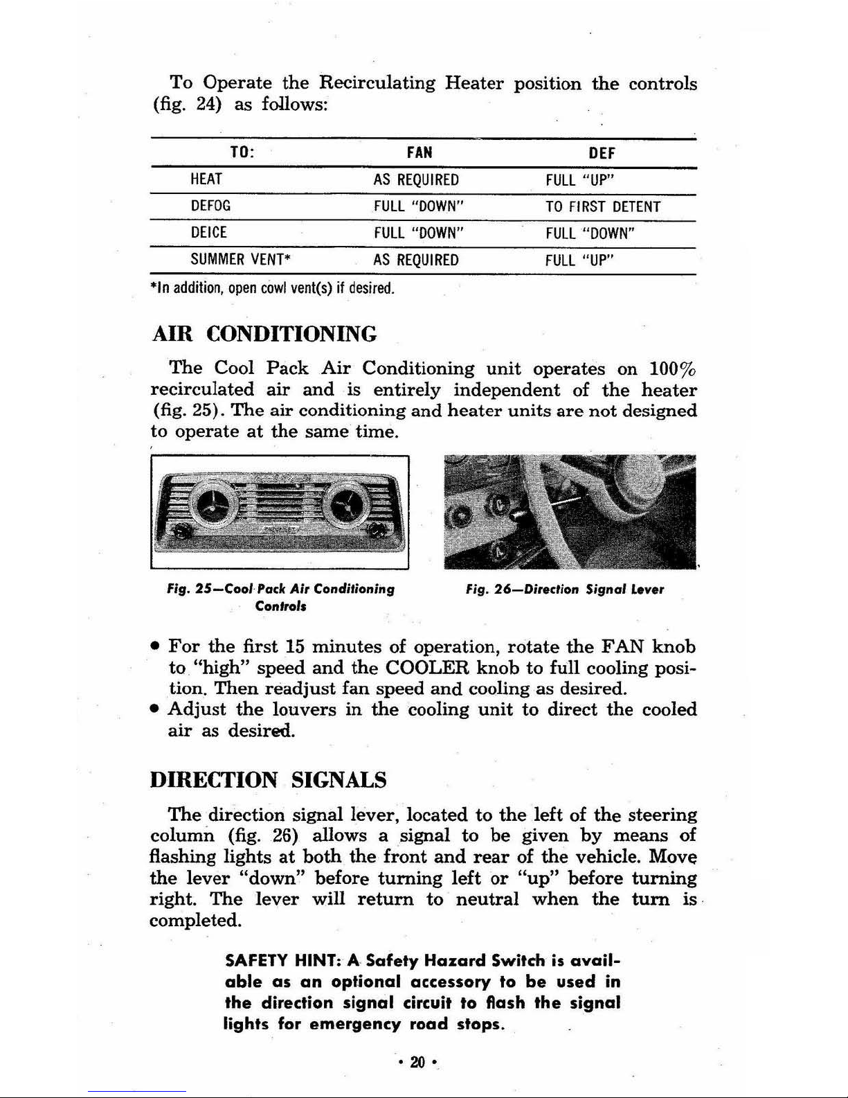
AIR CONDITIONING
The
Cool
Pack
Air
Conditioning
unit
operates
on 100%
recirculated
air
and
is
entirely
independent
of
the
heater
(fig. 25).
The
air
conditioning
and
heater
units
are
not
designed
to operate at
the
same time.
Fig.
25-CooI
-'oclc Air Conditioning
Contro' •
'J""t.
,.
~-
\ i.
b
''''
.'
~
.
.,..
"'t~
' .
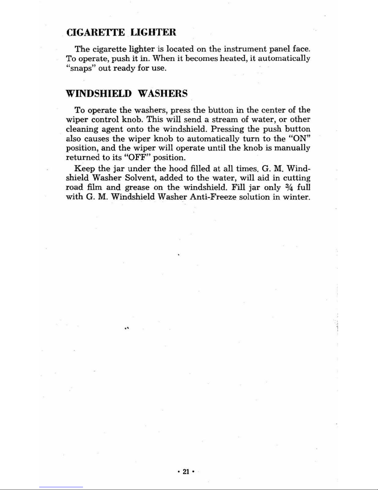
fig.
26-Di,..ction
Signa'
lever
•
For
the
first
15
minutes
of operation,
rotate
the
FAN
knob
to
"high"
speed
and
the
COOLER
knob
to full cooling posi-
tion.
Then
readjust
fan
speed
and
cooling as
desired
.
•
Adjust
the
louvers
in
the
cooling
unit
to
direct
the
cooled
air
as
desired.
DIRECTION SIGNALS
The
direction signal lever, located
to
the
left of
the
steering
column
(fig. 26) allows a signal to
be
given
by
means
of
flashing lights
at
both
the
front
and
rear
of
the
vehicle. Move
the lever
"down" before turning left or
"up"
before turning
right.
The
lever
will
return
to
neutral
when
the
turn
is
completed.
SAFETY
HINT:
A Safety Hazard Switch is
avail-
able
as
an
optional
accessory
to
be
used
in
the direction
signal
circuit to flash the
signal
lights for emergency road stops .
•
20'
CIGARETfE LIGHTER
The
cigarette
lighter
is
located
on the
instrument
panel
face.
To
operate,
push
it in.
When
it
become
s heated,
it
automatically
"snap
s"
out
ready
for use.
WINDSHIELD WASHERS
To
operate
the
washer
s,
pre
ss
the
blltt
on
in the
center
of
the
wiper
control
knob.
Thi
s will send a strea
m of
water, or
other
cl
eaning
agent
onto
the
windshield.
Pressing
the
push
butt
on
also
causes
the
wiper knob
to
automati
cally
turn
to
the
"ON
"
po
sition,
and
the
wiper
will
operate
until
the
knob
is
manuall
y
returned
to
its "OFF" position .
Ke
ep
the
jar
under
the
hood
filled
at
all
time
s. G. M.
Wind-
shield
Washer
Solvent, added
to
the
water,
will
aid
in cuttin
g
road
film
and
grease
on
the
windshield.
Fill
jar
only
% full
with
G. M.
Windshield
Washer
Anti-Fre
eze solution
in
winter.
·21
•
OPERATING
INSTRUCTIONS
PRE-STARTING
INSPECTION
The
following
inspections
are
not
necessary
each
time
the
vehicle
is
started providing
the
driver
has
recently
driven
the
vehicle
and
is
CERTAIN
that
attention
is
not
required.
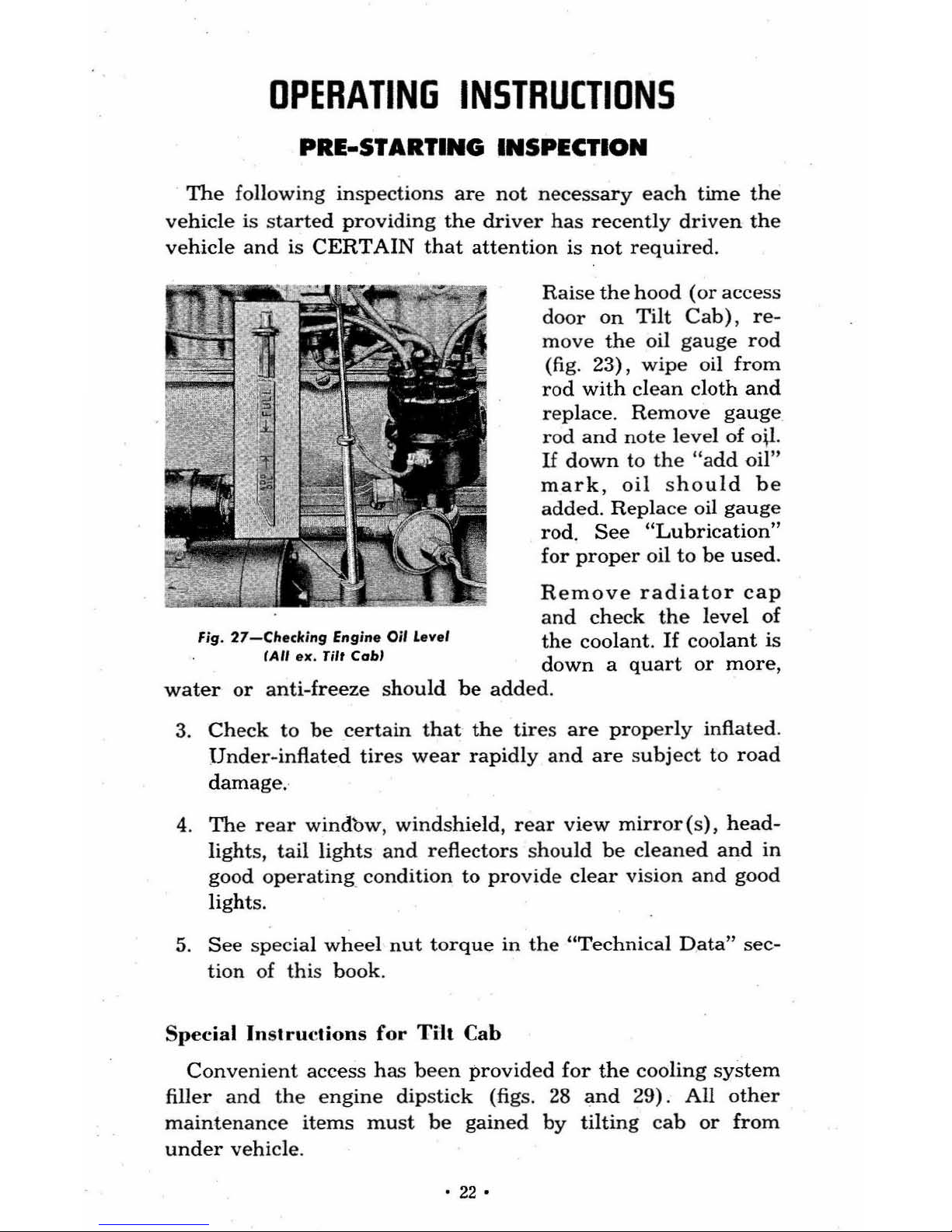
Raise
the hood
(or
access
door
On
Tilt
Cab),
re-
move
the
oil
gauge
rod
(fig. 23),
wipe
oil
from
rod
with
clean
cloth
and
replace.
Remove
gauge
rod
and
note
level
of oil.
If
down to the
lIadd
oil"
mark,
oil
sho
uld
be
added.
Replac
e oil
gauge
rod.
See
"Lubrication"
for
proper
oil
to
be
used.
Remove
radiator
cap
and
check
the
level
of
the
coolant.
If
coolant
is
Fig.
27-Cltecking
Engine
Oi'
L
eve
l
fAil
ex.
Tilt
Cahl
down
a quart or more,
water
or
anti-freeze
should
be
added
.
3.
Check
to
be
certain
that
the
tires
are
properly
inflated.
Under-inflated
tires
wear
rapidly
and
are subject
to
road
damage
.
4.
The
rear windbw, windshield, rear
view
mirror(s),
head-
light
s,
tail
lights
and
reflectors
sho
uld
be
cleaned
and
in
good operatinK condition to provide clear vision and good
lights.
5.
See
special
wheel
nut
torque
in
the
"Technical Data" sec-
tion
of
thi
s book.
Special Instruct
ions for
Tilt
Cab
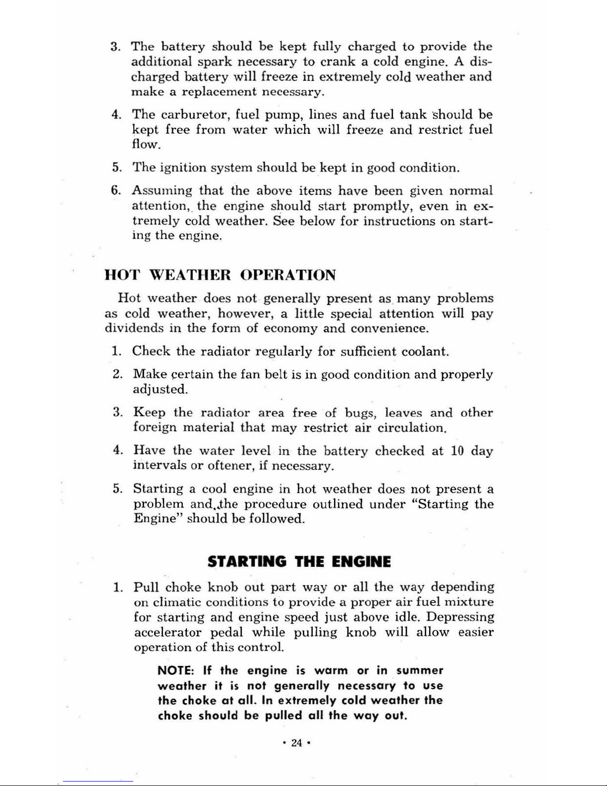
Convenient access has
been
provided for
the
cooling
system
filler
and
the
engine
dipstick
(figs.
28
and
29).
All
other
maintenan
ce
items
must
be
gained
by
tilting cab
or
from
under
vehicle.
• 22 •
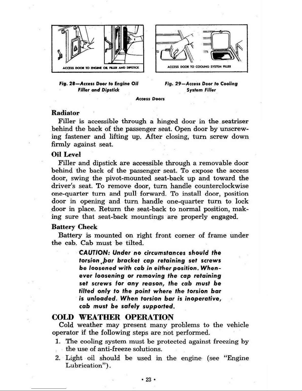
fig. 2'-'\"
...
0001' to
Engin.
Oil
fm.r
and
Dipstick
Acwu
Doors
Radiator
fig.
29-Acc.u
Door
10
Cooling
.
Sy.t.m
Filler
Filler
is accessible
through a hinged
door
in
the. seatriser
behind
the
back
of
the
passenger
seat. Open
door
by
unscrew-
ing
fastener
and
lifting up.
After
closing,
turn
screw
down
finnly
against
seat.
Oil Level
Filler
and
dipstick
are
accessible
through a removable
door
behind
the
back
of
the
passenger
seat.
To
expose
the
access
door,
swing
the
pivot-mounted
seat-back
up
and
toward
the
driver's seat.
To
remove
door, turn handle counterclockwise
one-quarter
turn
and
pull
forward. To install door, position
door
in
opening
and
turn
handle
one-quarter
turn
to
lock
door
in
place.
Return
the
seat-back
to
normal
position,
mak-
ing
sure
that
seat-back
mountings
are
properly
engaged
.
Bauery
Check
Battery
is
mounted
on
right
front
corner
of
frame
under
the
cab.
Cab
must
be
tilted
.
CAUTION: Under
no
circumslances should Ihe
torsion .par bracket
cap
retaining
set
screws
be
loosened
with
cab
in
either position,
When-
ever
loosening
or
removing
the cap retaining
set
screws
for
any
reason,
the
cab must
be
IiIled only 10 Ihe poinl where Ihe lorsion bar
is
unloaded
. When torsion bar is
inoperative,
cab
musl
be
safely
supporled.
COLD
WEATHER
OPERATION
Cold
weather
may
present
many
problems
to
the
vehicle
operator
if
the
following
steps
are
not
performed
.
1.
The
cooling
system
must
be
protected
against
freezing
by
the
use
of
anti-freeze
solutions.
2.
Light
oil
should
be
used
in
the
engine
(see
"Engine
Lubrication") .
•
23
•
3.
The
battery
shou ld
be
kept
fully
charged
to
provide
the
additional
spark
necessary
to
crank a cold
engine. A dis-
charged
battery
will
freeze
in
extreme
ly cold
weather
and
make a replacement
necessa
ry.
4.
The
carburetor,
fuel
pump
, li
nes
and
fuel tank 'shou
ld
be
kept
free
from
water whi
ch will
freeze
and res
tri
ct
fuel
flow.
5.
The
ignition
system
should
be
kept
in
good
condition.
6.
Assuming that
the
above
items
have
been
given nor
mal
attention
•. the
engine
sJ:tou
ld
start
promptly,
even
in
ex-
treme
ly cold
weather.
See
below
for
instructions
on
slar
l-
ing
the
engine.
H
OT
WEA
TH
ER OPE
RATIO
N
Hot
weather
does
not
gene
rally pr
esent as,
many
problems
as
cold
weather,
however,
a
litt
le
special attention
wi
ll
pay
dividends
in
the form
of
economy
and
convenience
.
1.
Check
the
radiator
regularly
for
sufficient
cool
ant.
2.
Make
certa
in
the
fan
belt
is in
good
condition and
properly
adjusted.
3.
Keep
the
radiator
area free
of
bugs,
leaves
and
other
foreign
material
that
may
restrict
air
circulation.
4.
Have
the
water level in
the
battery
checked
at
10
day
intervals
or
oftener,
if
necessary
.
5.
Starting
a cool
engine
in
hot
weather
does not
present
a
problem
and.~the
procedure
ou
tli
ned
under
"Starting the
Engine"
shou
ld
be
foll
owed.
STARTING THE ENGINE
1.
Pu
ll
choke
knob
out
part
way
or
all
the
way
depending
on
climatic
conditions
to
provide a proper
air
fuel
mixture
for
starting
and
engine speed just
above
id le.
Depressing
accelerator
peda
l w
hile pu
lli
ng knob
will all
ow
easier
operation
of
this
control.
NOTE:
If
the e
ngin
e is
warm
or
in
summ
er
weath
er
it
is
not
ge ne
rally
ne
cessary
to
use
the
choke at
all
. In e xtre
mely
cold
weather
the
choke should
be
pulled
all
Ihe
way
oul
.
•
24
•
2.
Make certain
the
tran
smission
gear shift
or
selec
tor
lever
is
in
neutral.
(On aut
oma
tic
transmi
ssion
mode
ls,
engin
e
will
not start
unl
ess
tran
smissio
n is
in
neutra
l "N" posi-
tion.
Pow
er
glide
mode
ls
may
also
be start
ed
in
Park "P"
position.)
Depre
ss
the clutch
pedal
,
if
so equipped, to
re-
lieve
the load on the
transmission.
3.
Pla
ce ignition
key
in switch
and
turn
key
clockwi
se
to
"
ON" po
sition.
4.
Turn
the
ignition key
clockwis
e again
st
spring
ten
sion
to
crank e
ngine.
RELEASE
KEY
AS
SOON
AS
ENGINE
STARTS
:
If
engine
does not
start
in 5 to
10
seco
nds,
re-
l
ease key
and check
to
see
if a
bove ins
tructions
have
been
pe
rformed
correctly.
5. AS'soon
as
engine start
s,
push
choke knob
in
part
way
and
a
dju
st
throttle
for smoo
th
idle.
6.
Note
oil
gauge
(or
indicator)
and
ammeter
(or
generato
r
indicator)
readin
gs.
Ammeter
should show
charge
or lig
ht
s
hould
be
off
unl
ess
engine is
idlin
g slowly.
The
charging
rat
e s
hown
on
an
ammeter
with a fu
lly ch
arged
battery
may
be
so slig
ht that
the
needle
may
appear to rema
in
cen
ter
ed
on
the
gauge and
not
move away
from
the gau
ge
center
mark. Th
e oil gau
ge should
show
some
pressure
or
indicator lig
ht
sho
uld
go
out.
On
vehicles equIpped
wit
h
oil
pressure lig
ht
be
cer
tain
lig
ht
is off be
fore continu
ing,
if
st
ill on,
stop engine
and
determine fault.
On
vehicl
es
eq
uipped
with
an
oil
pre
ssu
re
gauge,
in
unusuall
y co
ld
weath
er
the
oil
gauge
needle
may
move
all
the
way over
to
"60."
If
so,
run the
engine
just
above
idling speed
until
th
e indicat.or h
and
drop
s to
around
the center
of
the
gauge
befo
re
dri",ing
vehicle. The
choke
knob
should
be
push
ed
in
all
the
way
as
soon
as
the
engine is sufficie
ntly
warmed
up.
CAUTION:
Excessive
use
of
the
choke
. will
provide
a
fuel-air
mixture
too
rich
to
burn.
Some
of
this
unburned
fuel
will
leak
post
the
pistons
and
dilute
the
engine
oil
. This
will
cause
improper
lubrication,
excessive
engine
wear
and
poor
performance
.
7.
Check
the
temperature
gauge
while
operating ve
hicl
e.
Norma} operating
range
is
betw
ee
n "e"
and
"H"
mark
s.
Hot
weather, long hard driving, or
prol
onged idling may
cause the nee
dle
to
be
in the high
ra
nge
of
the
gauge
.
•
25
•
However,
if
the
needle
moves
clear
to
the
"H"
hot
end
of
the
gauge,
stop
the
engine
until
the cau
se
of
overheating
is
determined.
A
hot
engine
is
eas
ily flooded and
may
start hard.
If
the
carburetor
is flooded,
proceed
as
follows:
a.
Tu
rn
on
ignition.
b.
Hold
accelerator
at
wide
open thr
ottle
position.
c.
DO
NOT pull
choke
knob
out.
d.
Engage starter
by
turning key
clockwise
against
spring
tension.
e.
When
engine
starts,
release
starter,
and close
throttle
slowly.
NOTE
: Do
not
remove
the
radiator
cop
when
engine
is
excessively
hot,
do
not
put
water
in
an
overheated
engine,
and
do
not
run
en-
gine
when
indicator
is
above
"H."
OPERATING THE:
SYNCHROMESH TRANSMISSION
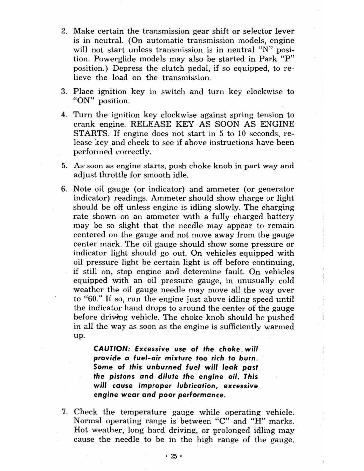
Three.Speed -The gear shi
ft
control
on
trucks
equipped with
this transmission
is
located
on
the
righ
t s
ide
of
the
stee
ring
column.
This transmission
uses
the
conventional "H"
shifting
pattern
as sh
own
in
Figure 30.
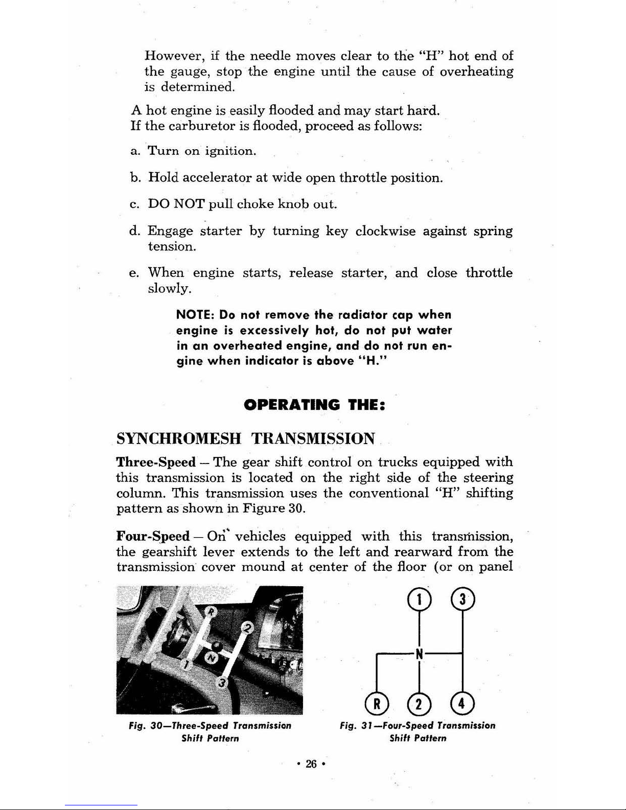
Four-S:peed
-
Ori~
vehicles
equip
ped
with
this
transmission,
the
gearshift lever
extends
to
the
left
and rearward from
the
transmission' cover
mound
at
center
of
the
floor
(or
on
panel
Fig.
30-Three-Speed
Transmission
ShUI
Paller"
•
26
•
?~
r~1
Fig.
3J-Four-Speed
Transmission
Shif,
Pallem

between
front
sea
ts
on
tilt
cab
mo
dels).
Thi
s l
ever
is used
to
s
hift
the
tran
smission
gears
to
the d
esire
d position.
Figure
31
sh
ows
the shifting pattern.
This
pattern
is
also sh
own
on the
co
ntrol lever knob.
Five-Speed -
When the vehicle
is
equipped
with
anyone
of
the
five-speed
transmi
ssions,
the shifting
pattern
is s
hown
on
the shift
control lever knob a
nd
in Figure
32. The
contro
l l
ever
is
in the same
position
as desc
rib
ed
above
under "four-speed."
NOTE: If
the
vehicle
is
equipped
with a two
speed
rear
axle,
refer
to
the
Two
Speed
Axle
instructions
later
in
this
section
.
tiJ
tfJ
r~l
~
~1
CLARK 0 .0 .
SPICER
0 .0.
NEW
PROCESS
CLARK
S
PICER
Fig.
32-Fiv
e·Spee
d Transmission Shiff PaUerns
AUTOMATIC ·'fRANSMISSION
Pow
erg
lid
e
This optional
transmi
ssion
is a completely
aut
omatic u
nit
which
repla
ces
the
standard
clutch
and
transmis
sion.
Selectiv
e
control
is
obtained
through
the
selector
lever
which
is
located
On
the
right sid
e of
the
stee
rin
g co
lum
n.
The
diff~rent
ranges
are
indicated
on a quadrant
(fig.
33).
Towing
and
Pushing
Cautions-If
your
truck
must
be
towed,
place sel
ector
lever
in
"N"
pos
iti
on.
Do
not
exceed
30
miles
per hour.
If
the transmission
is
not
opera
ting p'roperly, the
propeller
sha
ft s
hould
be disco
nnect
ed from
the rear axle,
or
the
rear
wheels shou
ld
be
raised b
efore
any
towing
is
at-
tempte
d.
Should
it
ever
be
nece
ssary
to
start
the engine
by
• 27 •
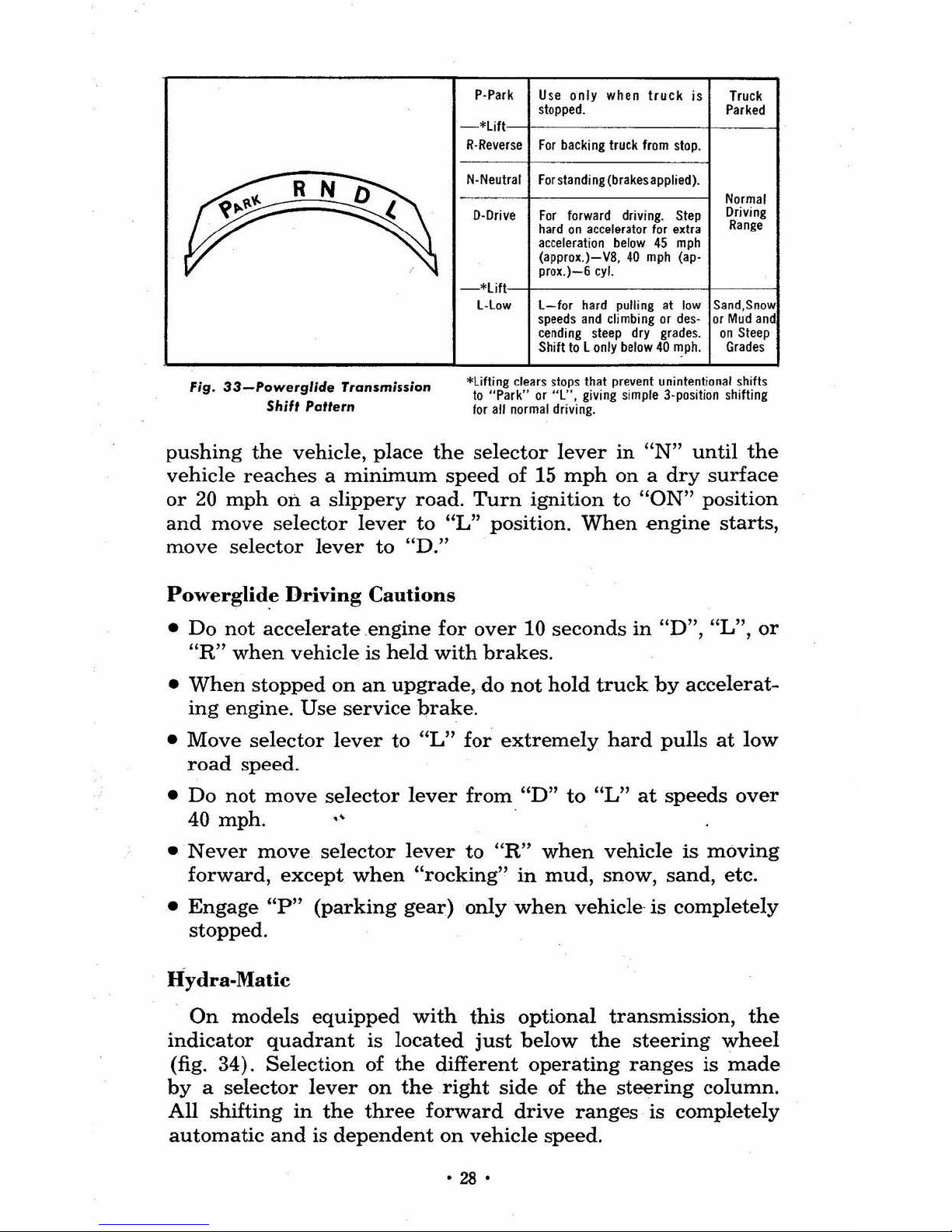
Fig.
33-Powerglide
Transmission
Shift
Partern
P·Park Use
only
wilen truck is Tru
ck
stopped. Parked
R·Reverse
For
backing truck from stop.
N·Neulral Forslanding{brakesapplied).
D·Orive For forward driving. Stell
hard
on
accelerator
for
extra
accelerati
on
below
4S
mph
{allllro~.)-V8,
40
mph (ap·
Ilrox.)-6cyl.
Normal
Driving
Range
-*lift
-t
-------t---
---I
l·low
l-for
hard pulling at
low
Sand,Snow
speeds and climbing or des·
orMudand
cending steep dry grades.
on
Steep
Sh
ift
tolonlybelow40~ph
.
Grades
*liftingclears
slops Ihat prevent unintentional shifts
to
"Park" or
"l",
giving simple 3·position shifting
lor
all
normal driving.
pushing
the
vehicle,
place
the
selector
lever
in
"N"
until
the
vehicle
reaches a minimum
speed
of 15
mph
on a dry
surface
or
20
mph
on a slippery
road.
Turn
ignition
to
"ON"
position
and
move
selector
lever
to
"L"
position.
When
engine
starts,
move
selector
lever
to
"D."
Powerglid~
Driving
Cautions
•
Do
not
accelerate.engine
for
over
10
seconds
in
uD", "L", or
"R"
when
vehicle
is
held
with
brakes.
•
When
stopped
on
an
upgrade,
do
not
hold
truck
by
accelerat-
ing
engine.
Use
service
brake.
•
Move
selector
lever
to
"L"
for
extremely
hard
pulls
at
low
road
speed.
•
Do
not
move
selector
lever
from
"D"
to
ilL"
at
speeds
over
40
mph.
•
Never
move
selector
lever
to
"R"
when
vehicle
is
moving
forward,
except
when
"rocking"
in
mud,
snow,
sand,
etc.
•
Engage
up"
(parking
gear)
only
when
vehicle
is
completely
stopped.
Hydra-Malic
On
models
equipped
with
this
optional
transmission,
the
indicator
quadrant
is
located
just
below
the
steering
wheel
(fig.
34).
Selection
of
the
different
operating
ranges
is
made
by a selector
lever
on
the
right
side
of
the
steering
column.
All
shifting
in
the
three
forward
drive
ranges
is
completely
automatic
and
is
dependent
on
vehicle
speed,
•
28
•
 Loading...