

Chesterton TwinHybrid 4400H Installation, Operation And Rebuild Instructions
INSTALLATION, OPERATION and
REBUILD INSTRUCTIONS
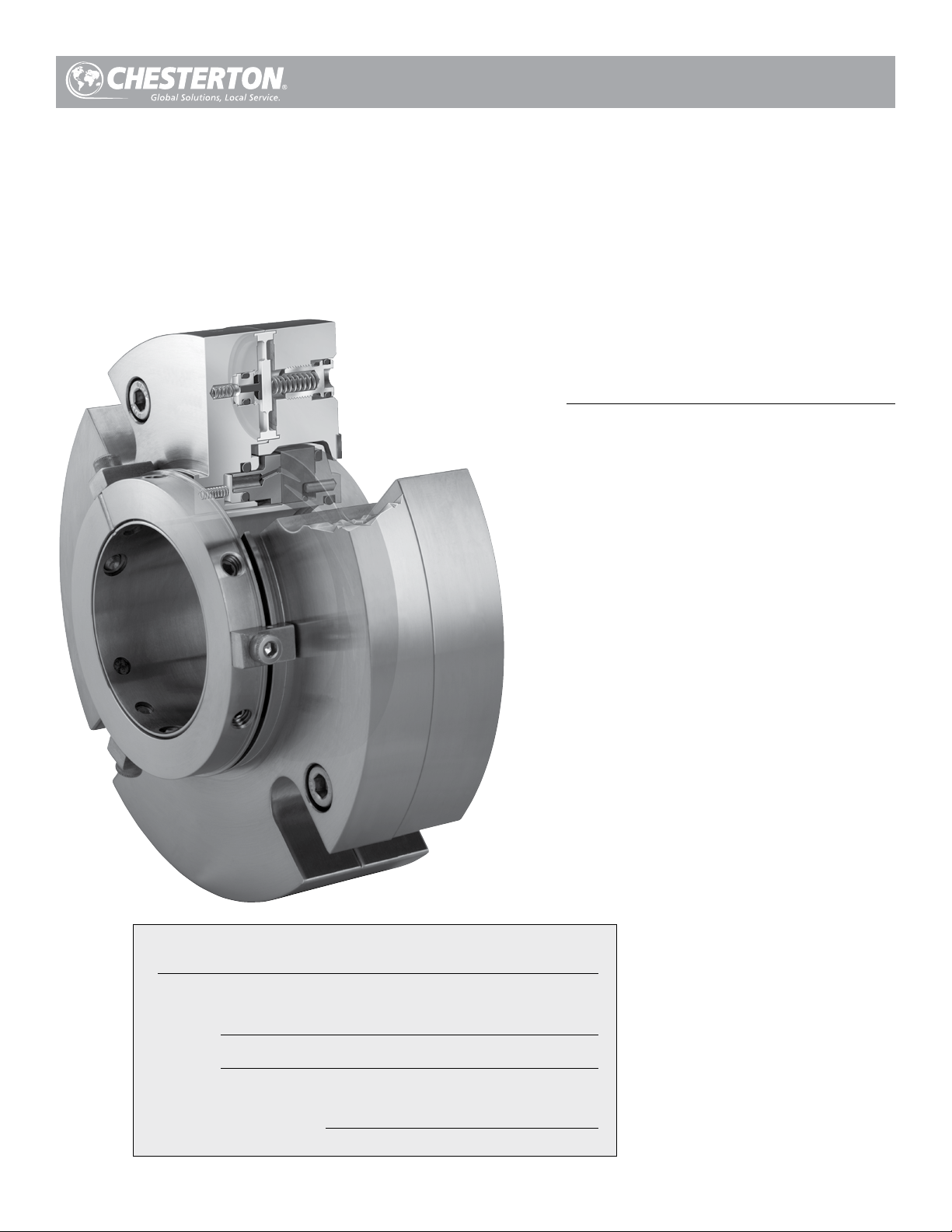
4400H TwinHybrid™
Gas Seal
Installation, Operation and Rebuild Instructions
TABLE OF CONTENTS
1.0 Cautions ................................................................... 2
2.0 Transport and Storage .......................................... 2
3.0 Description ............................................................... 2
3.1 Parts Identification ..........................................................2
3.2 Operating Parameters .....................................................3
3.3 Standard Materials .........................................................3
3.4 Intended Use ..................................................................3
3.5 Dimensional Data ..................................................... 4 - 5
Seal Data Reference
(Insert seal and equipment data here for future reference)
ITEM #
SEAL
(Example: 4400H – 50 mm SSC/CB/FKM/S)
4.0 Preparation for Installation ................................... 6
4.1 Equipment .....................................................................6
4.2 4400H TwinHybrid™ Gas Seal ........................................6
5.0 Seal Installation ....................................................... 7
6.0 Commissioning/Equipment Start-up ................. 8
7.0 Decommissioning/Equipment Shut Down ....... 8
8.0 Spare Parts .............................................................. 8
9.0 Seal Maintenance and Repair ..................... 8 - 11
9.1 4400H Trouble Shooting .................................................8
9.2 4400H TwinHybrid™ Gas Seal Rebuild Instructions .. 9 - 11
INSTALLATION DATE
1.0 CAUTIONS
These instructions are general in nature. It is assumed
that the installer is familiar with seals and certainly with
the requirements of their plant for the successful use of
mechanical seals. If in doubt, get assistance from someone
in the plant who is familiar with seals or delay the installation
until a seal representative is available. All necessary auxiliary
arrangements for successful operation (heating, cooling,
flushing) as well as safety devices must be employed. These
decisions are to be made by the user. The decision to use this
seal or any other Chesterton seal in a particular service is the
customer’s responsibility.
2.0 TRANSPORT AND STORAGE
Transport and store seals in their original packaging.
Mechanical seals contain components that may be subject to
alteration and ageing. It is therefore important to observe the
following conditions for storage:
3.0 DESCRIPTION
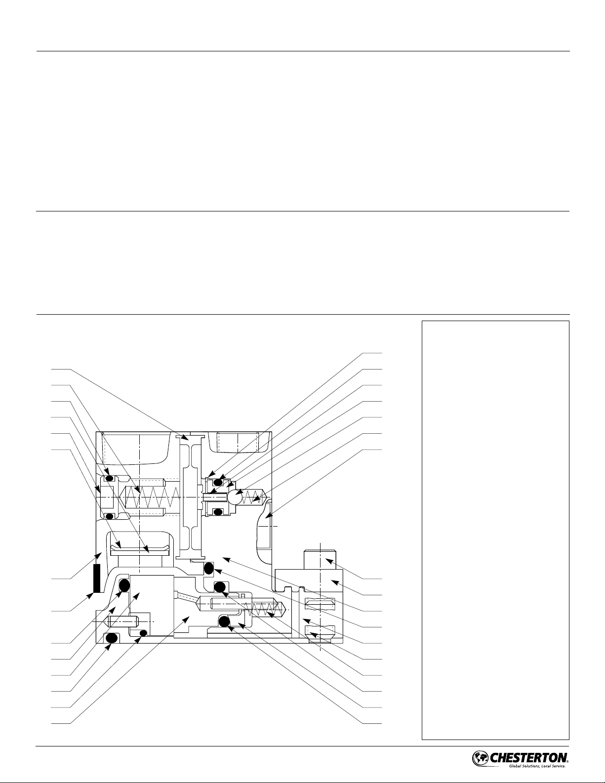
3.1 Parts Identification
Figure 1
20
19
18
35
17
36
6
3
4
1
5
2
28, 31-34, 37 (not shown in this view
7
8
)
Do not touch the mechanical seal for any reason while it is
operating. Lockout or uncouple the driver prior to personal
contact with the seal. Do not touch the mechanical seal
while it is in contact with hot or cold fluids. Ensure that all
the mechanical seal materials are compatible with the
process fluid. This will prevent possible personal injury.
• Dust free environment
• Moderately ventilated at room temperature
• Avoid exposure to direct sunlight and heat.
• For elastomers, storage conditions according to ISO 2230
should be observed.
KEY
1 – Sleeve Assembly
22
23
21
24
25
26
29
16
15
9
10
14
27
30
11
13
12
2 – Shaft O-Ring
3 – Gasket
4 – Rotary O-Ring
5 – Rotary Seal Ring
6 – Adapter
7 – Rotary Cushion O-Ring
8 – Stationary Seal Ring
9 – Gland
10 – Inter Gland O-Ring
11 – OD Stationary O-Ring
12 – ID Stationary O-Ring
13 – Pusher Plate
14 – Lock Ring
15 – Centering Clip
16 – Socket Head Cap Screw
17 – Adjusting Screw
18 – Screw O-Ring
19 – Inboard Spring
20 – Diaphragm
21 – Actuator
22 – Snap Ring
23 – Seat O-Ring
24 – Seat
25 – Ball
26 – Outboard Spring
27 – Dog Point Set Screw
28 – Cup Point Set Screw
29 – Gland Screws
30 – Spring
31 – 1/4" Pipe Plug
32 – 1/8" Pipe Plug
33 – 3/8" Pipe Plug
34 – Cap Plug
35 – Filter Disk
36 – Retaining Clip
37 – Support Gasket
2

3.0 DESCRIPTION cont.
3.2 Operating Parameters*
Speed Limits:
25 m/s (5000 fpm) Maximum
1,3 m/s (250 fpm) Minimum
Pressure Limits:
710 Torr (28" Hg) to 20 bar g (300 psig)
25 mm – 65 mm (1.000" -2.625")
510 Torr (20" Hg) to 17 bar g (250 psig)
70 mm – 90 mm (2.750" – 3.625")
Temperature Limits:
To 260°C (500°F) Maximum (elastomers)
* Consult Chesterton Mechanical Seal Application Engineering for higher
operating conditions.
3.3 Standard Materials
Faces :
Carbon Stationary Seal Ring
Sintered Silicon Carbide Rotary Seal Ring
Elestomers:
FKM, EPDM, FEPM, FFKM
Metal Parts:
316SS body
Alloy C-276 springs and drive pins
Hardened set screws (standard)
3.4 Intended Use
The mechanical seal is specifically designed for the intended
application and is to be operated within the operating
parameters as specified. For use beyond the intended
application and/or outside the operating parameters, consult
Chesterton Mechanical Seal Application Engineering to confirm
the suitability of the mechanical seal prior to putting the
mechanical seal in operation.
3
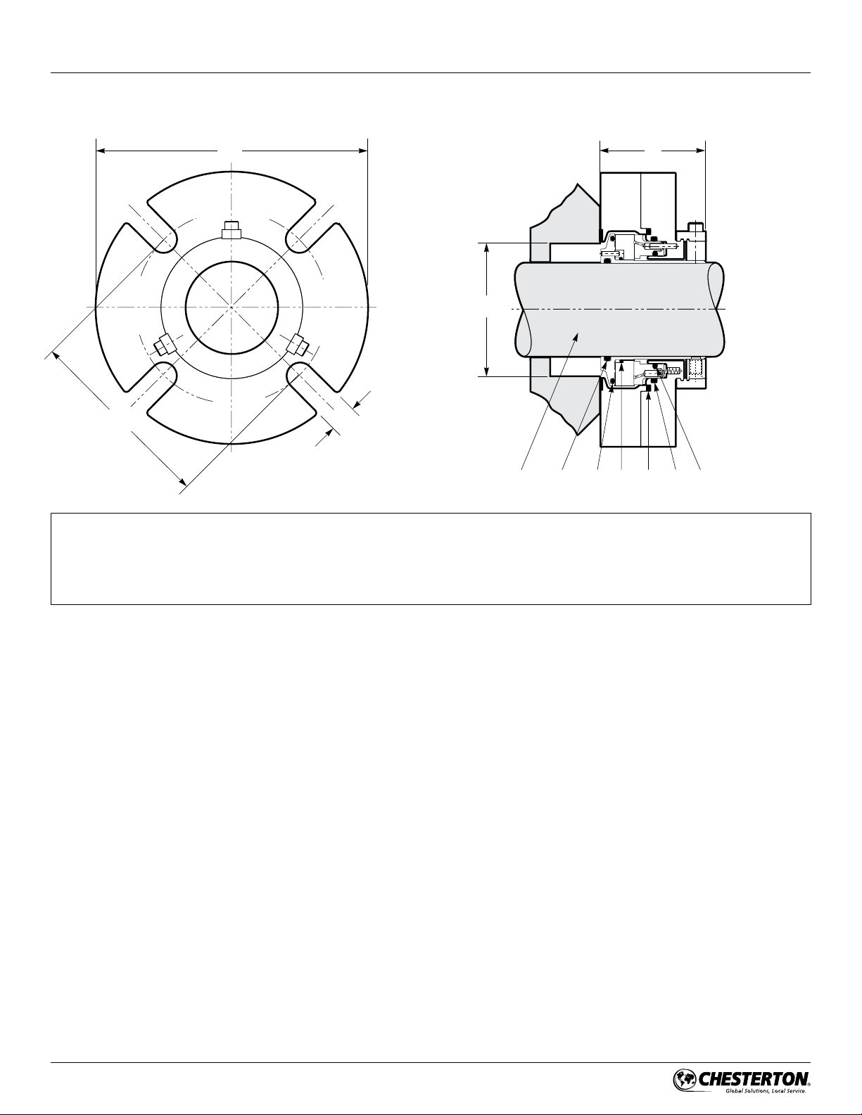
3.0 DESCRIPTION cont.
3.5 Dimensional Data (Drawings)
Figure 2
G MIN
KEY (chart)
A – Shaft Size
B – Maximum Gland Diameter
C – Stuffing Box Inside Diameter
F – Outboard Seal Length
B
C
H
TA
G – Maximum Bolt Circle by Bolt Size
H – Slot Width
T – Shaft O-Ring
U – Rotary Seal O-Ring
V – Rotary Cushion O-Ring
W – Stationary Seal O-Ring (outside diameter)
X – Stationary Seal O-Ring (inside diameter)
Y – Gland Adaqpter O-Ring
F
VU Y W
X
4
 Loading...