

Chesterton 170L Operation And Maintenance
INSTALLATION, OPERATION and
MAINTENANCE INSTRUCTIONS
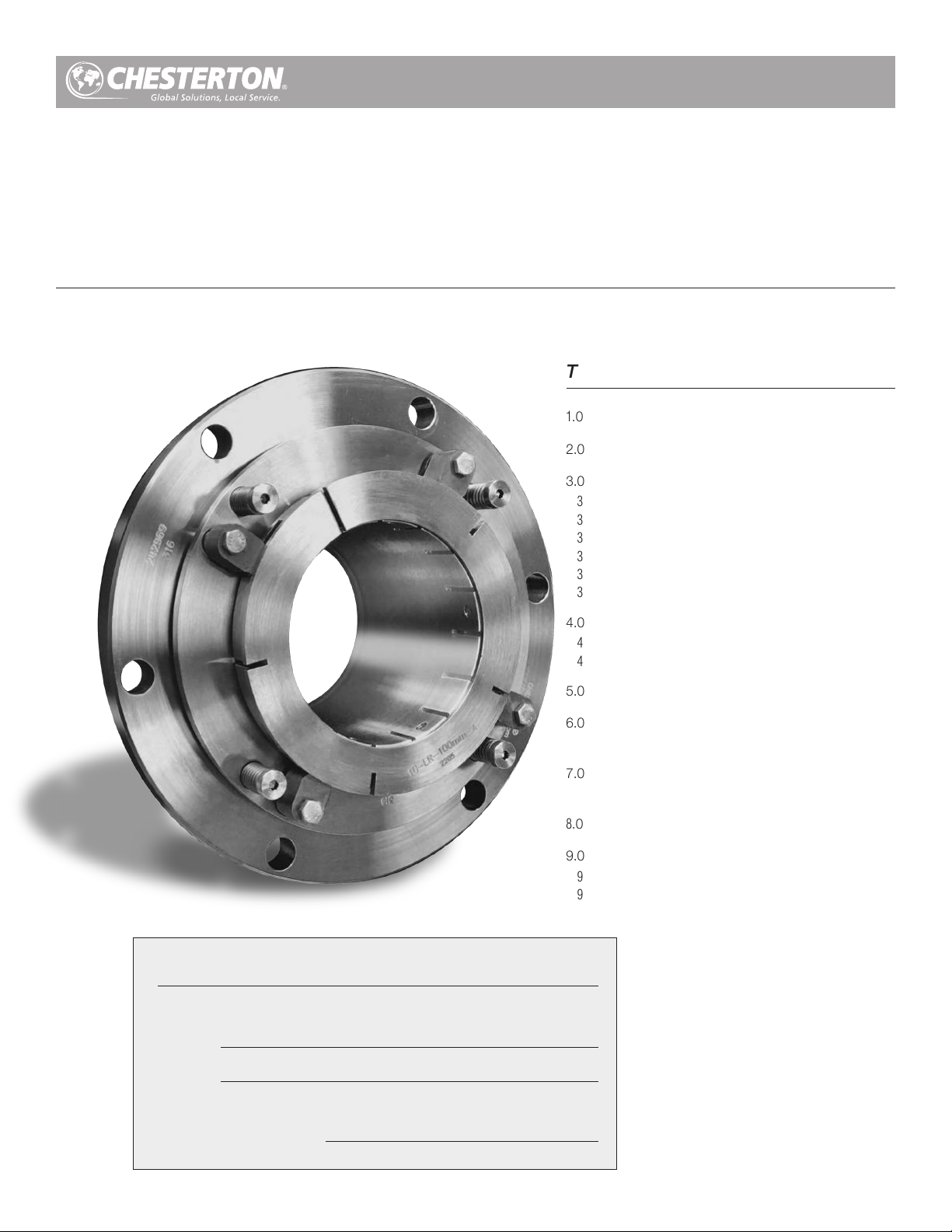
170L Slurry Cartridge
Single Seal—Wet Version
Designed to fit Weir™ AH series pump
Installation, Operation and Rebuild Instruction
TABLE OF CONTENTS
1.0 Cautions ..............................................................2
2.0 Transport and Storage .........................................2
3.0 Description...........................................................2
3.1 Parts Identification .................................................................. 2
3.2 Operating Parameters .............................................................. 3
3.3 Intended Use ........................................................................... 3
3.4 Pump Frame Size Availability Data .......................................... 4
3.5 Clamped Gland Configuration ................................................ 5
3.6 Bolted Gland Configuration ..................................................... 5
Seal Data Reference
(from Box Label)
ITEM #
4.0 Preparation for Installation ....................................6
4.1 Equipment ............................................................................... 6
4.2 Mechanical Seal ...................................................................... 7
5.0 Seal Installation .................................................... 7
6.0 Commissioning / Equipment
Start-up ................................................................................... 8
7.0 Decommissioning / Equipment
Shut Down .............................................................................. 8
8.0 Spare Parts ..........................................................8
9.0 Seal Maintenance and Repair ...............................8
9.1 Returning Seals for Repair....................................................... 8
9.2 Seal Maintenance ................................................................... 9
SEAL
(example 170L 100mm SSC/TC)
INSTALLATION D AT E
1.0 CAUTIONS
These instructions are general in nature. It is assumed
that the installer is familiar with seals and certainly with
the requirements of their plant for the successful use of
mechanical seals. If in doubt, get assistance from someone
in the plant who is familiar with seals or delay the installation
until a seal representative is available. All necessary auxiliary
arrangements for successful operation (heating, cooling,
flushing) as well as safety devices must be employed. These
decisions are to be made by the user. The decision to use this
seal or any other Chesterton seal in a particular service is the
customer’s responsibility.
2.0 TRANSPORT AND STORAGE
Transport and store seals in their original packaging.
Mechanical seals contain components that may be subject to
alteration and ageing. It is therefore important to observe the
following conditions for storage:
• Dust free environment
3.0 DESCRIPTION
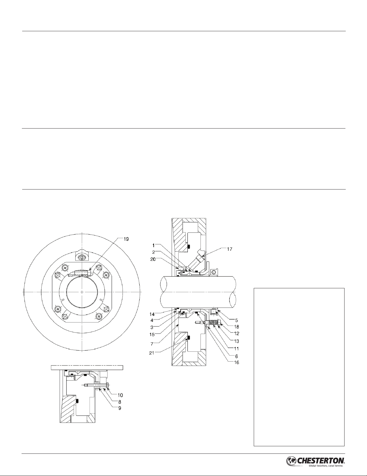
3.1 Parts Identification
3.1.1 Clamped Gland Configuration
Do not touch the mechanical seal for any reason while it is
operating. Lockout or uncouple the driver prior to personnel
contact with the seal. Do not touch the mechanical seal
while it is in contact with hot or cold fluids. Ensure that all the
mechanical seal materials are compatible with the process
fluid. This will prevent possible personal injury.
• Moderately ventilated at room temperature
• Avoid exposure to direct sunlight and heat
• For elastomers, storage conditions according to ISO 2230
should be observed
KEY
1 – Stationary Seal Ring
2 – Rotary Seal Ring
3 – Rotary Gasket
4 – Sleeve Assembly
5 – Lock Ring Assembly
6 – Pusher
7 – Gland
8 – Centering Clip
9 – Centering Clip Spacer
10 – Hex Screw
11 – Spring
12 – Shoulder Screw
13 – Washer
14 – Shaft O-Ring
15 – Rotary O-Ring
16 – Stationary O-Ring
17 – Pipe Plug
18 – Dog Point Set Screw
19 – TORX Socket Head Cap Screw
20 – SpiralTrac® (optional)
21 – Gland O-Ring
22 – Eye Bolts (not shown)
2
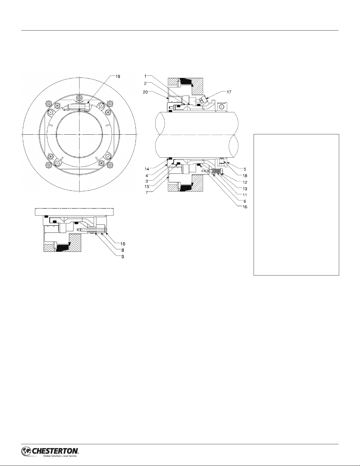
3.0 DESCRIPTION cont.
3.1 Parts Identification
3.1.2 Bolted Gland Configuration
KEY
1 – Stationary Seal Ring
2 – Rotary Seal Ring
3 – Rotary Gasket
4 – Sleeve Assembly
5 – Lock Ring Assembly
6 – Pusher
7 – Gland
8 – Centering Clip
9 – Centering Clip Spacer
10 – Hex Screw
11 – Spring
12 – Shoulder Screw
13 – Washer
14 – Shaft O-Ring
15 – Rotary O-Ring
16 – Stationary O-Ring
17 – Pipe Plug
18 – Dog Point Set Screw
19 – TORX Socket Head Cap Screw
20 – SpiralTrac® (Optional)
3
3.0 DESCRIPTION cont.
3.2 Operating Parameters*
Pressure:
60-145 mm 250 psig (17 bar g)
180-220 mm 150 psig (8 bar g)
†Seal pressure capabilities are dependent on the f luid sealed, temperature,
speed, and face combination.
Speed Limits:
60-145 mm – 20 m/s (4000 FPM)
180-220 mm – 12 m/s (2400 FPM)
Consult Seal Applications Engineering for higher applications.
Temperature Limits:
Elastomers
To 150°C (300°F) EPDM
To 205°C (400°F) FEPM, FKM
To 260°C (500°F) FFKM
Standard Materials*
All Metal Parts: 316 SS / EN 1.4401
A2205 / EN 3.017
Springs: Alloy C276 / EN 2.4819
Rotary Face: SSC, TC
Stationary Face: SSC, TC
Elastomers: EPDM, FEPM, FKM, FFKM
3.3 Intended Use
The mechanical seal is specifically designed for the intended
application and is to be operated within the operating
parameters as specified. For use beyond the intended
application and/or outside the operating parameters, consult
Chesterton to confirm the suitability of the mechanical seal
prior to putting the mechanical seal in operation.
*Other materials available upon request.
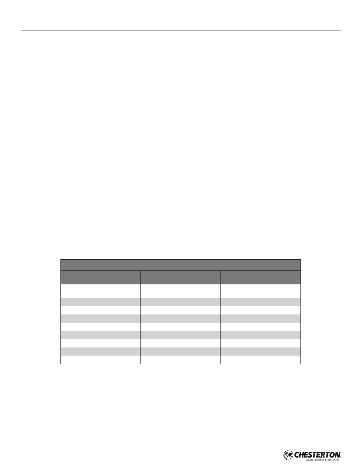
3.4 Pump Frame Size Availability Data
170L Slurry Seal Wet End - Seal Assembly Availability
Weir Pump Model / Frame
1.5/1 B-AH
2/1.5 B-AH
3/2 C-AH 60 x
4/3 C-AH 60 x
4/3 D-AH 85 x
6/4 D-AH 85 x
6/4 E-AH 100 x
8/6 E-AH 100 x
8/6 F-AH 130 x
10/8 ST-AH 180 x
Shaft Size (mm)
A
50 x
Standard
44
 Loading...