

Page 1

Introduction
Chapter 1 Introduction
Page 2
Introduction
Before reading this User‟s Manual,
you should understand the
following things.
Thanks for your purchase of Chery vehicle.
In order to operate your vehicle properly
and guarantee your rights and benefits,
please spend some time to read this
manual carefully.
This manual provides the important
instructions and hints on the daily driving
and regular maintenance and care, with the
purpose for your familiarity with the
operation of your vehicle. Only the more
understanding to your vehicle can
guarantee the safety and economy of the
vehicle driving as well as enjoy the
pleasure thereof.
Any improper operation may damage your
vehicle as well as may be deprived of your
maintenance right.
The periodical maintenance to your
vehicle will help maintain the driving
performance and used value of your
vehicle. The Chery authorized service
stations all over the country boasted
numerous repair experts to provide you
with service anytime.
The repair personnel of all authorized
service stations, who passed the
professional trainings, can properly repair
your vehicle and vehicle equipment. The
spare parts in Chery authorized service
station are of Chery genuine spare parts.
Equipment Scope
This manual defined the maximum
possible equipment scope installed in
accordance with the Eastars series
(SQR7240&SQR7200) model plan till the
print date, namely for all the standard
equipment and optional equipment in
Eastars series model, some equipment may
be supplied in the future or may be only
available in certain markets. Therefore,
some items in this manual may not apply
to your vehicle.
This vehicle model is equipped with two
types of engine (Mitsubishi and ACTECO),
and users can read it according to different
symbols.
Alarm Symbols within This
Manual
During the vehicle operation, to
reduce the damage to the vehicle
and the vehicle equipment and to
avoid the person injury, you can findthe
answers in this manual, which is included
in the explanation for the alarm symbols
with triangle. Please read carefully and
abide by the contents thereof.
The equipment marked with
asterisk (*) is only used in lot
size on certain model structures,
which is supplied as optional equipment
for some models or is only available in
certain markets.
When this symbol is present on
the vehicle, make sure to read
the related chapters of this
manual before any operations.
Environmental Protection
We must contribute our
responsibility and liability in the
working of environmental
protection. It’s the important step to
achieve such objective by operating your
vehicle properly and disposing the used
cleaning articles and lubricating materials
in accordance with the laws and
regulations. This manual displayed the
information on this aspect by means of
tree symbol.
Page 3

Introduction
New Vehicle Inspection
Before delivering the vehicle to you, the
dealer of Chery Company has already
performed the vehicle inspection in
accordance with the regulations of Chery
Automobile Co., Ltd.
The dealer of Chery Company should fill
in the vehicle delivery date in the "Vehicle
Delivery Inspection Certificate‖ column of
this manual and seal with the stamp of
dealing agency.
The dealer should verify the entire vehicle
performance and introduce the operation
knowledge of the vehicle against the
―Chery Vehicle Sale & Delivery Card‖
that to be dually signed by the salesman
and the user.
Run in of New Vehicle
Due to the manufacture and assembling
deviations, the frication resistances
between the moving components of the
new vehicle at the initial stage of
operation will be much greater than the
ones in normal condition. The run in
effects of the vehicle at the initial stage of
operation will exert great influence on the
use lifetime, working reliability and
economy of the vehicle, therefore, the use
of the new vehicle must abide by the run
in regulations strictly.
Run in Regulation within 1,000km
Full speed driving is absolutely
prohibited;
Generally, do not drive the vehicle at
the speed above 100 km/h;
Avoid driving at the top speed at
whichever gear.
Run in Regulation from 1,000km
to 1,500km
Increase to the top speed gradually or
drive at the allowable max engine
speed.
Notice during Run in Period:
For the driving of vehicles with engine
tachometer, the allowed short period top
engine speed is 6,000r/min. During the
manual gearshift, make sure to shift to the
next high gear when the engine tachometer
indicator reaches red indication area at the
latest.
Avoid the running of engine at
unnecessary high speed. The
earliest shift to high gear will help
save the fuel, reduce the working noise as
well as diminish the environmental
pollution.
The engine speed should not be excessive
low during driving. Shift to the low gear
when the engine runs toughly.
In cold state, you don’t run the engine at
top speed at neutral gear or any other drive
gear.
Page 4

Introduction
The new tires don’t have the best adhesion
at the beginning of use; therefore, the tires
also need run in. The vehicle speed should
be relatively low during the first 100km
driving and the driving should be
extremely careful.
The new brake friction lining also needs
run in, since the brake doesn't have ideal
friction force during the first 200km
driving. During this period the brake
effects are a little poor, therefore the
pressure on brake pedal may be reasonably
increased. Such condition is also
applicable each time the friction lining is
replaced with a new one.
When the new vehicle traveled for 800km,
the wheel nuts must be re-tightened to the
specified torque. Please refer to the
chapter ―Capability and Specification
Parameters‖ of this manual for correct
torque values. Also, if the wheel has been
replaced or the wheel nuts have been
loosened, then the wheel nuts should be
re-tightened in accordance with the
specified torque after traveling for 800km.
“One-To-One” Service
In order to provide you with better service
and vehicle use, the dealer of Chery
Company will appoint one service
consultant to serve you at the purchase of
your vehicle. In case of any problems
during your vehicle use, you may contact
your service consultant, who will provide
you with the best services.
Page 5
Introduction
Vehicle Delivery Inspection Evidence:
This is to certify that this vehicle has completed the
vehicle delivery inspection defined by Chery
Automobile Co., Ltd. and its quality met with the
technical specification of Chery Automobile Co., Ltd.
Vehicle Delivery Date: _____________
Dealer Stamp:
Vehicle Owner Responsible Service Station Name
Name (Unit)
Address
Principal
Tel: Tel:
Page 6
Introduction
Vehicle Delivery Date
Dealer Stamp
Model:
Body VIN No:
Engine Serial No.:
Transmission Serial No.:
Page 7
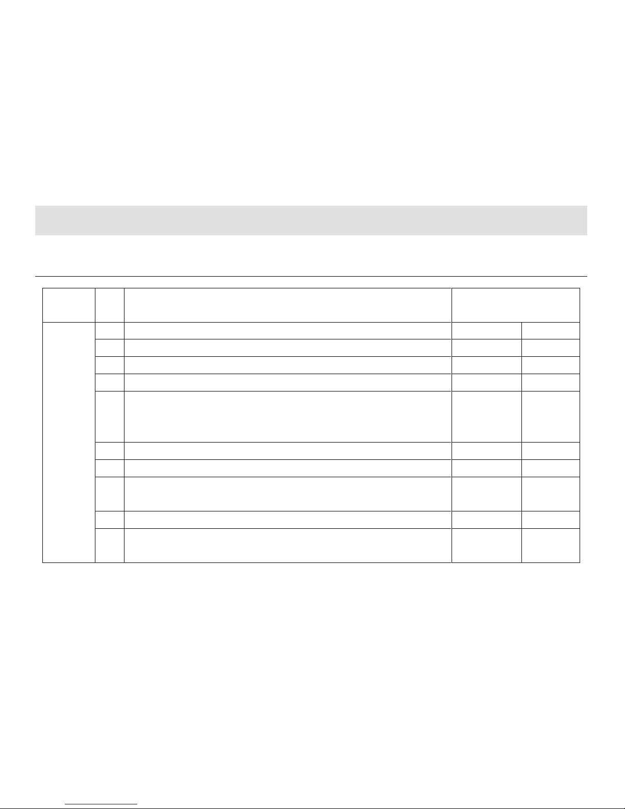
Introduction
Chery Vehicle Sale & Delivery Sheet
Category
No.
Item
Whether inspected OK and
clearly explained
Entire Vehicle Performance
1
Engine
Yes □
No □
2
Engine oil, brake liquid, steering liquid, coolant, battery liquid
Yes □
No □
3
VIN number, engine serial number, nameplate and other identifications
Yes □
No □
4
Entire vehicle locks and keys
Yes □
No □
5 Entire vehicle lamps, including head lamp, turn lamp, fog lamp, combined lamp,
compartment lamp, brake lamp, backup lamp, tail lamp, reading lamp, door
lamp, and instrument lamp
Yes □
No □
6
Windscreen glass and body paint
Yes □
No □
7
Speedometer, engine tachometer, odometer
Yes □
No □
8
Hub cap, spare tire in luggage compartment, vehicle attached tools and entire
vehicle operation manual
Yes □
No □
9
Safety belt, cigarette lighter, A/C switches and vent, glove box and sun visor
Yes □
No □
10
Glass lifter, rear view mirror, wiper, washer, horn, radio (CD player) and
antenna
Yes □
No □
Page 8

Introduction
Operation
Knowledge
1
93# gasoline fuel
Yes □
No □
2
Normal operation during run in
Yes □
No □
3
Operation of entire vehicle lamps
Yes □
No □
4
Meaning of alarm indicators
Yes □
No □
5
Correct maintenance period and mileage
Yes □
No □
6
Vehicle maintenance items in winter and summer.
Yes □
No □
7
Correct understanding of cooling system/coolant usage.
Yes □
No □
8
Correct operation of A/C
Yes □
No □
9
Notices for vehicle start
Yes □
No □
10
Correct operation of audio equipment
Yes □
No □
Salesman Signature: Date: User Signature: Date:
Page 9

Introduction
“One-To-One” Counseling Service Card
User Name: Vehicle Purchase Date:
Sales Agency: Model:
Vehicle VIN Number:
Following items should be validated by the user:
I. Related items confirmation at vehicle delivery (―√" for Yes as
―×‖ for No)
Basic vehicle operation method has been introduced and the
onsite delivery inspection is certified OK.
Quality warranty policy has been introduced.
Vehicle driving notice has been introduced.
The importance of vehicle periodical maintenance and
maintenance period/mileage has been introduced.
The importance of vehicle maintenance/repair at Chery
authorized service station has been noted.
Maintenance Manual and User’s Manual has been handed over
and the reading is reminded.
The function and operation method of service hotline of Chery
Company has been noted.
II. ―One-To-One‖ counseling service mode introduction (―√‖ for
Yes as ―×‖ for No)
Contact the service counsel instead of anyone else in case of
any problems or needs.
The service counsel appointed by the service station is the
exclusive person to communicate and contact with the user.
One user is only served by one service counsel: "One-To-One‖
User may choose other service consultant when dissatisfied
with current service consultant.
III. Major Job introduction of service counsel (―√‖ for Yes as ―×‖
for No)
Repair maintenance service reception
Complaint acceptance
Periodical maintenance reminding visits
Repair/Maintenance consultant explanation
Periodical greeting visits
Repair/maintenance reservation acceptance
Service activity reminding visits
Annual authentication reminding/acceptance
Important festival greeting
Other activities of user’s needs
IV. Establishment of ―One-To-One‖ counseling service
relationship.
Service Counsel Card
User Signature/Date: Service Counsel Signature/Date:
Form One Saved by Service stations
服务站留存
Page 10

Introduction
“One-To-One” Counseling Service Card
User Name: Vehicle Purchase Date:
Sales Agency: Model:
Vehicle VIN Number:
Following items should be validated by the user:
I. Related items confirmation at vehicle delivery (―√" for Yes as
―×‖ for No)
Basic vehicle operation method has been introduced and the
onsite delivery inspection is certified OK.
Quality warranty policy has been introduced.
Vehicle driving notices have been introduced.
The importance of vehicle periodical maintenance and
maintenance period/mileage has been introduced.
The importance of vehicle maintenance/repair at Chery
authorized service station has been noted.
Maintenance Manual and User’s Manual has been handed over
and the reading is reminded.
The function and operation method of service hotline of Chery
Company has been noted.
II. ―One-To-One‖ counseling service mode introduction (―√‖ for
Yes as ―×‖ for No)
Contact the service counsel instead of anyone else in case of
any problems or needs.
The service counsel appointed by the service station is the
exclusive person to communicate and contact with the user.
One user is only served by one service counsel: "One-To-One‖
User may choose other service counsel when dissatisfied with
current service counsel.
III. Major job introduction of service counsel (―√‖ for Yes as ―×‖
for No).
Repair maintenance service reception
Complaint acceptance
Periodical maintenance reminding visits
Repair/Maintenance counsel explanation
Periodical greeting visits
Repair/maintenance reservation acceptance
Service activity reminding visits
Annual authentication reminding/acceptance
Important festival greeting
Other activities of user’s needs
IV. Establishment of ―One-To-One‖ counseling service
relationship.
Service Counsel Card
User Signature/Date: Service Counsel Signature/Date:
Form Two Saved by Customers
客户留存
Page 11
Instrument Panel
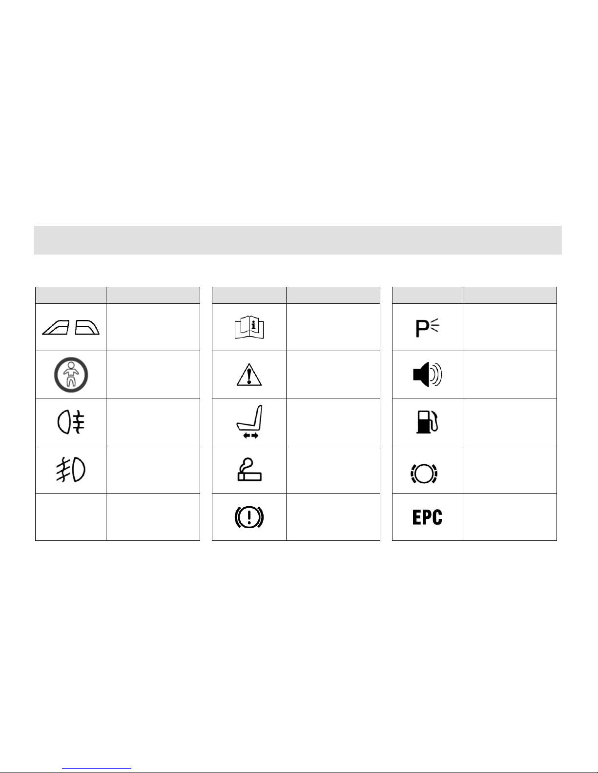
Common Vehicle Symbol Instruction
Symbol
Definition
Symbol
Definition
Symbol
Definition
Front and rear side
power window
Please refer to the
User Manual
Parking lamp
Rear window switch
prohibited
Safety warning
Sound alarm
Rear fog lamp
Power seat
Fuel
Front fog lamp
Cigarette lighter
Brake pad alarm
indicator
A/C
A/C system
Brake system
Electronic throttle
Trouble indicator
Page 12
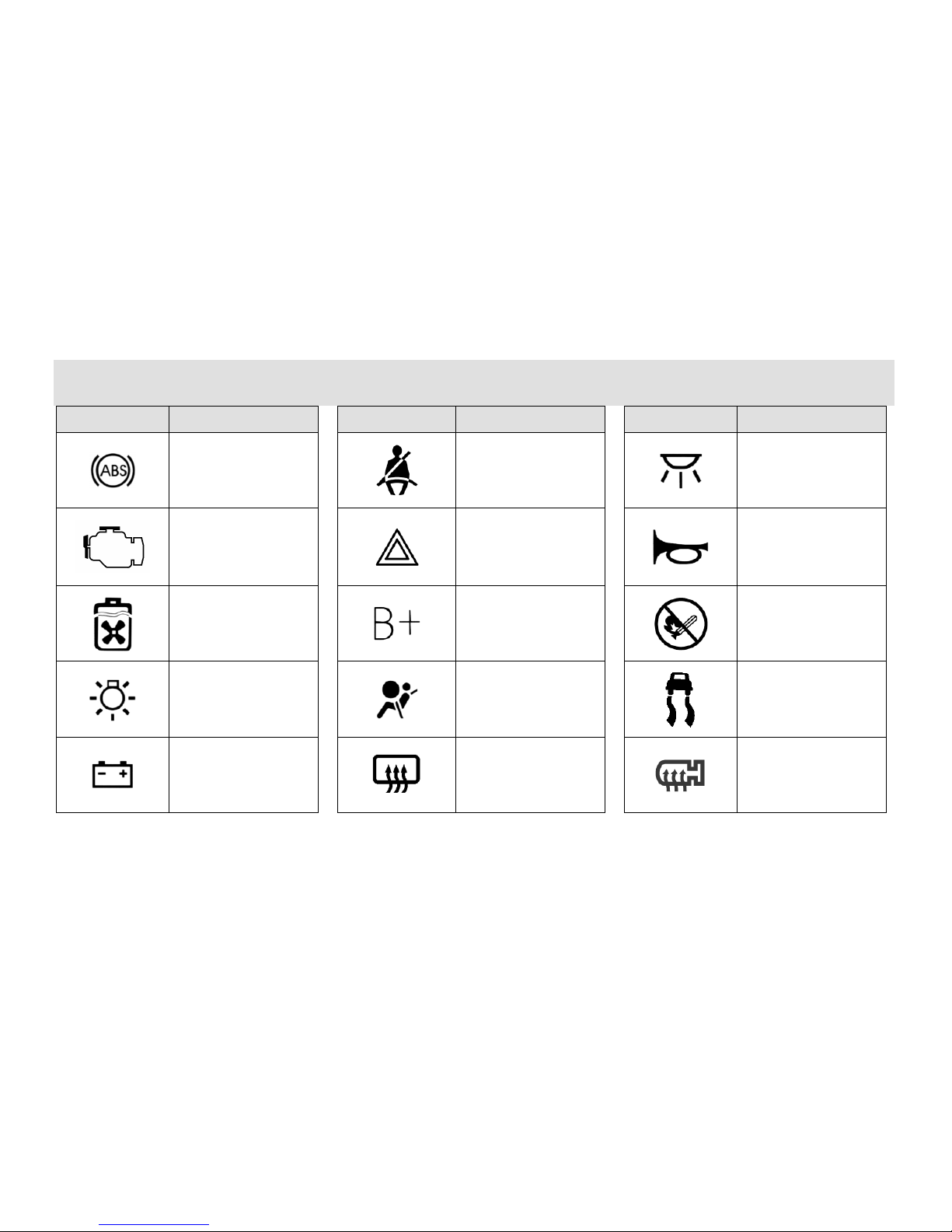
Instrument Panel
Symbol
Definition
Symbol
Definition
Symbol
Definition
ABS
Fasten the safety belt
Interior lamp
Engine
self-examination
trouble light
Danger flash alarm
lamp
Horn
Engine coolant fan
Power + pole
No fire
Head lamp switch
Air bag
Anti-sideslip
indicator lamp
Battery
Rear window heating
indicator
Rear view mirror
heating
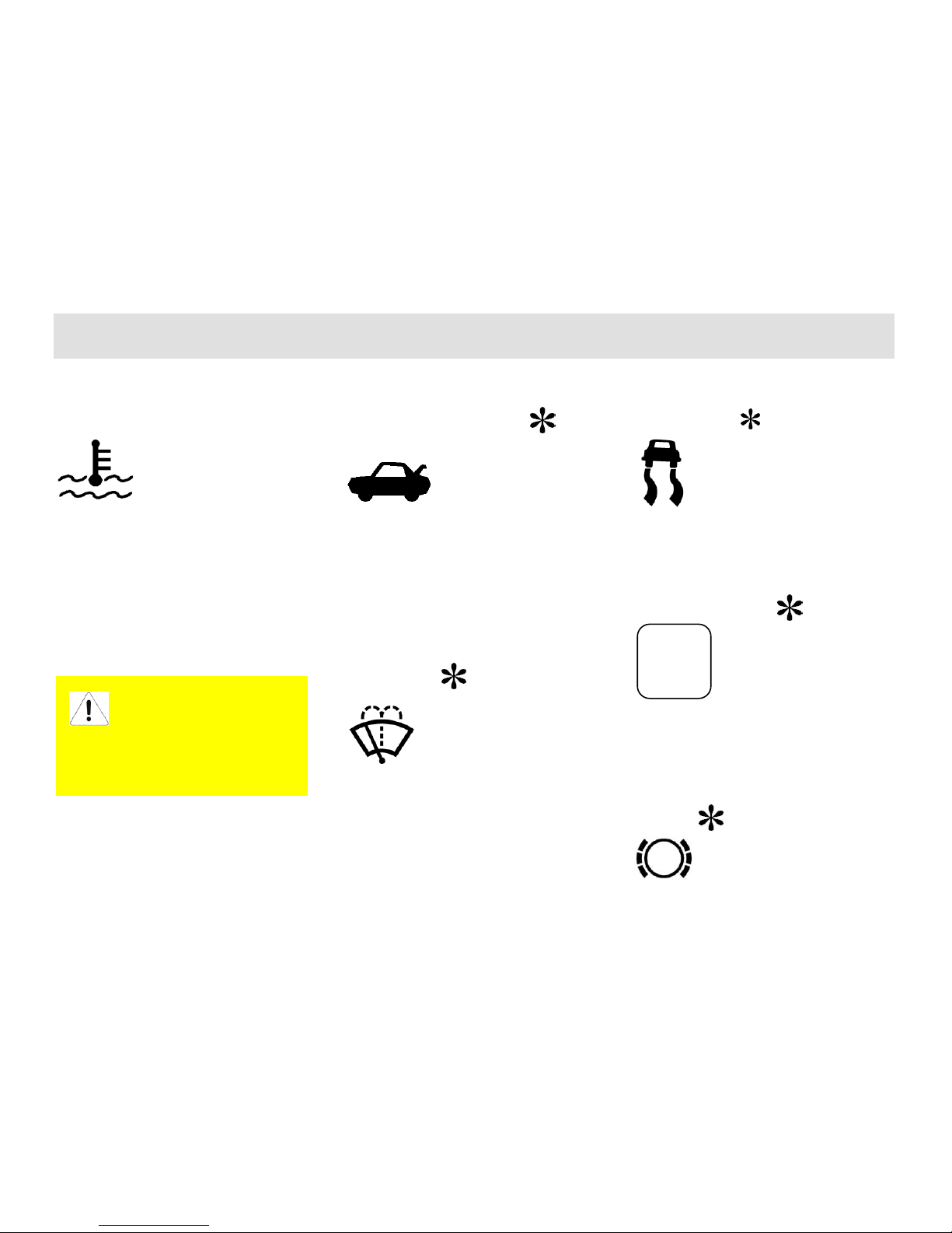
Page 13

Instrument Panel
Symbol
Definition
Symbol
Definition
Symbol
Definition
Jack
Caution---fan
Windscreen
defrosting
High beam lamp
Acidic
Vehicle maintenance
indicator
Low beam lamp
Air bag identification
Wiper switch
AT
Trouble indicator
lamp
Snowfield mode
indicator lamp
Page 14

Instrument Panel
Chapter 2 Instrument Panel
Page 15
Instrument Panel
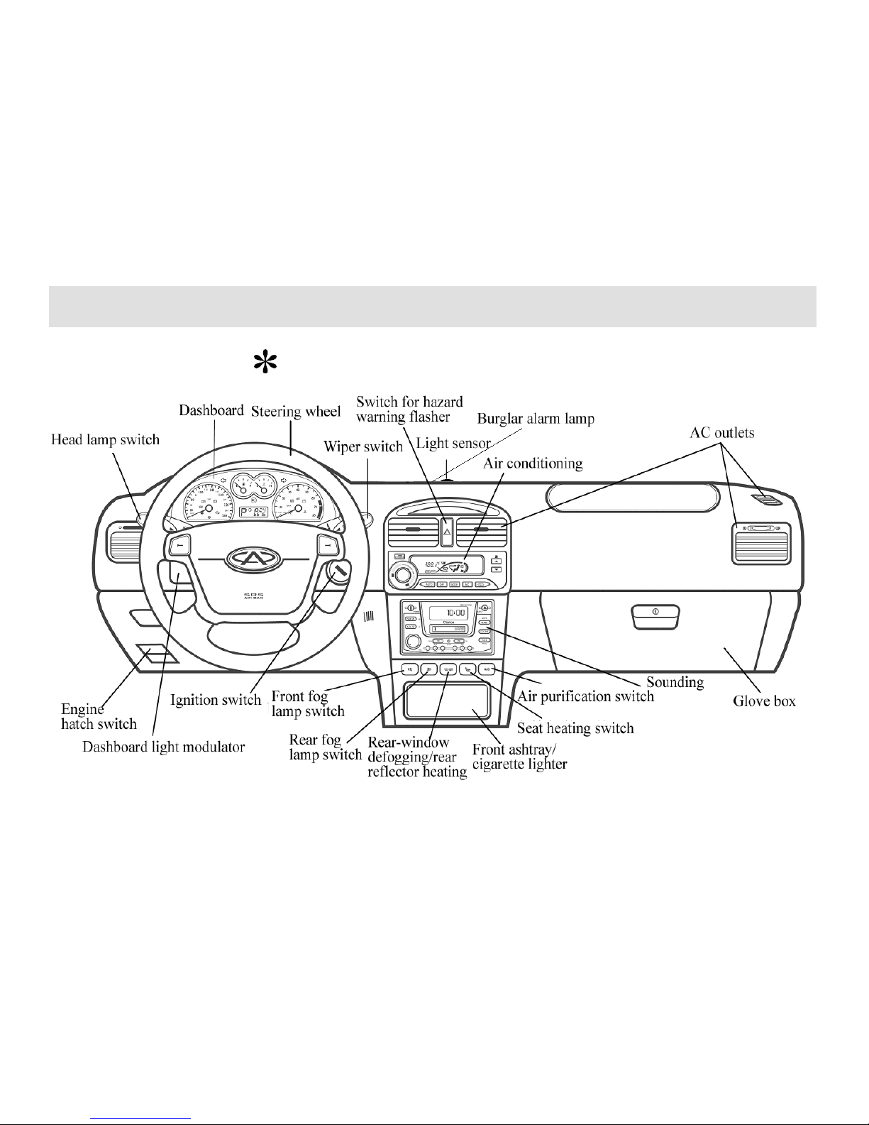
Instrument Panel ( )
Page 16

Page 17
Instrument Panel
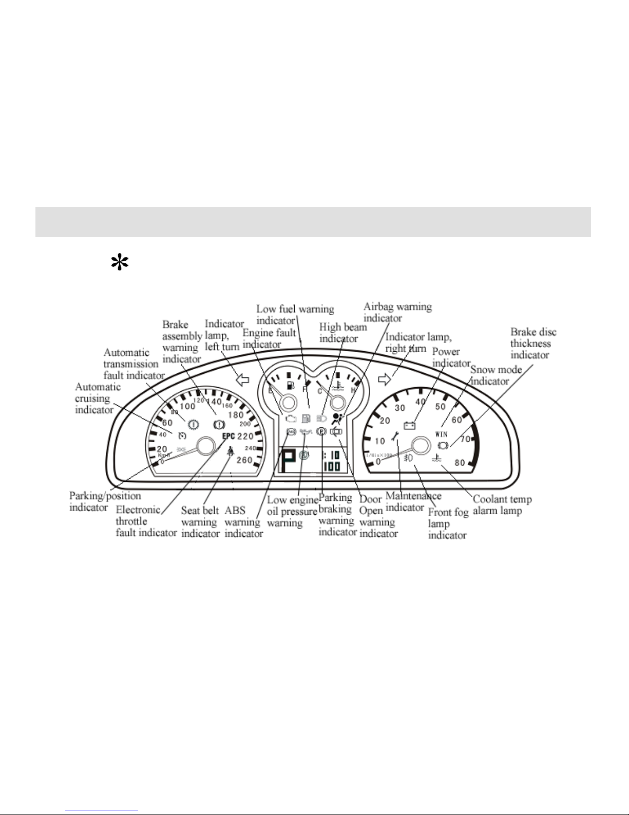
Dashboard ( )
Page 18

Page 19
Instrument Panel
Warning Device
Warning device indicates operating status
of driver’s car and whether the vehicle has
some problems that possibly result in
serious damages or injuries. If the car fails
in some system function, the warning
indicator concerned will light up or blink.
When ignition switch is turned on, the
majority warning indicators should be ON
for a short period, indicating system
self-check underway. If some warning
indicator remains OFF, please turn to
Chery chartered service station for help. If
some warning indicator keeps ON or
blinking after the engine is started, please
turn to Chery chartered service station
immediately for examination and repairs
of relevant systems.
Low fuel level warning
indicator
When oil level of fuel tank is short of 10
liters, the indicator will be immediately
ON for alarming, while fuel gauge pointer
will point to the red alarm scale mark.
When the indicator is ON, please replenish
fuel.
ABS warning indicator
When ignition switch is turned on, the
indicator will be ON for a short period,
and the ABS system will have a self-check
to determine if the system functions well.
If the indicator keeps ON or blinking after
the ignition switch is turned on or during
the journey, it suggests that the ABS
system is being impaired by fault(s).
However, the vehicle still functions in
conventional braking (without ABS),
unless otherwise the braking system alarm
lamp also lights up. In such a case, turn to
Chery chartered service station for
examination & repairs as early as possible;
but you should drive prudently, avoiding
driving at a high speed. Refer to the
Section ―Braking‖ for important points for
attention related to use of the ABS system.
Parking braking warning
indicator
The indicator functions only when ignition
switch is turned on.
The indicator will keep ON if the parking
brake lever is pulled up.
Braking system warning
indicator
When ignition switch is turned on and the
indicator is ON, it is suggested that the
brake fluid level is so low that more brake
fluid should be filled to raise the level
between MIN mark and MAX mark.
Please ask Chery chartered service station
to check the system.
Page 20
Instrument Panel
If the braking system
warning indicator lights up
during running, it is shown
that one of the dual braking loop has
a fault. In such a case, drive
prudently. Turn to Chery chartered
service station nearby immediately
for examination & repair by
professionals. In consideration of
serious degrading of braking
performance and prolonged braking
distance, a much longer distance
should be kept from the car in the
front during running. Press the
pedal hard in braking according to
the situation.
If ABS warning indicator and
braking system warning indicator
keep ON simultaneously, stop your
car immediately with safety assured.
Please put the car at Chery
chartered service station for
inspection of the braking system.
Door Open warning
indicator
When ignition switch is turned on, the
indicator will be ON if any car door fails
to be closed rightly.
Parking/position indicator
(green)
The indicator will be ON when the
position indicator lights up.
Seat belt warning indicator
When ignition switch is turned on, the
warning indicator will be ON to prompt
driver to well fasten the safety belt if the
driver doesn’t have his safety belt
fastened.
Engine fault indicator
When ignition switch is turned on, the
warning indicator will be ON to show that
electrical control system of engine is under
self-check. If the system has no faults, the
indicator shall be OFF after the engine is
started.
If during running, the indicator is ON, it is
shown that the electrical control system of
engine has a fault. Please turn to Chery
chartered service station for examination
& repair as quickly as possible.
Electric throttle fault
indicator ( )
Page 21
Instrument Panel
When ignition switch is turned on, the
warning indicator is ON, and electrical
control system of engine will make a
self-check of electric throttle. If the system
has no faults, the indicator shall be OFF
when the self-check is over. If the
indicator keeps ON, check the electric
throttle necessarily.
If during running, the indicator is ON, it is
shown that the electric throttle of engine
has a fault. Please turn to Chery chartered
service station for examination & repair as
quickly as possible.
Automatic transmission
fault indicator ( )
When automatic transmission circuit has a
fault, automatic transmission fault
indicator should be constantly ON if
ignition switch is in the position of ON, no
matter whether the vehicle is on the run.
Stop driving it and contact Chery
chartered service station immediately.
Automatic cruising
indicator ( )
When ignition switch is in the position of
ON, press down the ON button of cruising
controller, and the automatic cursing
indicator in the dashboard blinks to
suggest initiation of pre-cruising; if during
running, automatic cruising system works,
the indicator keeps constantly ON to show
that the system is at work.
Snow mode indicator
( )
When ignition switch is in the position of
ON, press down the snow mode button
near the gear shift operating rod, and the
snow mode indicator in the dashboard will
be ON. Start the engine and push the
operating rod at the position D (Drive),
and the speed variator starts at 2nd gear to
drive your car (it is suggested that the
mode be selected when starting is done
from such roads as cladded by snow with
low attachment coefficient). Then, press
down the snow mode button, and the snow
mode indicator in the dashboard is OFF;
the system exits from the snow mode.
High beam indicator
The indicator will be ON when high beam
is used or front headlight blinks.
Page 22

Page 23
Instrument Panel
Steering signal indicator
There are indicator lamp, left turn and
indicator lamp, right turn. When the
indicator lamp, left turn or right turn is
turned on, the steering signal indicator
concerned will blink (relatively slow).
When hazard warning flasher is set on, the
indicator lamp, left turn, indicator lamp,
right turn, and left –and-right turn signal
indicator will blink simultaneously.
If a turn signal indicator blinks at a two
times normal rate, it is shown that the turn
light concerned has a fault.
Airbag warning indicator
( )
When ignition switch is turned on, fault
check indicator should be OFF after
blinking six times. If the fault indicator
lasts 6 seconds and is then OFF, it is
shown that some fault code exists though
it doesn’t affect regular work of the airbag
system.
If during running, the fault indicator is ON,
it is shown that there is a fault. Send the
car to Chery chartered service station for
system check.
Low engine oil pressure
warning indicator
When ignition switch is turned on, the
indicator should blink immediately, and
should be OFF after the engine is started.
If the indicator is not OFF after the engine
is started or blinks during running, please
stop the car immediately to quench the
engine and check the engine oil level.
If the oil level is over low, replenish oil
immediately.
Please turn to Chery
chartered service station
for check if engine oil is
consumed too quickly.
Power indicator
When ignition switch is turned on, the
indicator is ON. It should be OFF after the
engine is started.
If the indicator is not OFF or is ON during
running, stop the car immediately, shut off
the engine, and check dynamo belt.
If the dynamo belt is normal, please keep
on driving to Chery chartered service
station nearest for examination & repair
immediately. However, accumulator
battery will keep continuous discharge
during running. Thereby, all unnecessary
electric appliances should be turned off,
including air conditioning system.
If dynamo belt has been damaged,
continuous driving should be suspended.
Ask professionals for examination &
repair.
Page 24

Page 25
Instrument Panel
Coolant temp warning
lamp
When ignition switch is turned on, the
indicator will be OFF after being ON for
seconds. If the indicator fails to be OFF
after several seconds or lights up during
running, stop the car immediately, shut off
the engine, cool the engine, and check
coolant level. Contact Chery chartered
service station immediately.
Beware of scalding!
When the engine is hot,
cooling system is at high
temperature and under high
pressure. Therefore, open radiator
cap only when the engine is cooled.
Keep off radiator fan!
Luggage compartment
gate open warning lamp
( )
The indicator appears at the display screen
above central air outlet of instrument panel.
When ignition switch is turned on, the
indicator will be ON if luggage
compartment gate fails to be closed
rightly.
Windscreen washing
indicator ( )
The indicator appears at the display screen
above central air outlet of instrument panel.
The indicator is ON when windshield
wiper works.
Sideslip protection
indicator ( )
The indicator appears at the display screen
above central air outlet of instrument panel.
The indicator is ON when sideslip
protection function is enabled.
TCS indicator ( )
The indicator appears at the display screen
above central air outlet of instrument panel.
The indicator is ON when tractive force
control system works.
Brake strip thickness
warning lamp ( )
TCS
Page 26

Page 27

Instrument Panel
The indicator is ON for alarming when the
brake strip is heavily worn. Drive
carefully and hurry to a service station for
brake strip replacement.
Servicing & maintenance
indicator ( )
When mileage counter reads preset
mileage accumulated (5000km), the
warning indicator will be ON to prompt
users to go to a service station for
servicing and maintenance of the entire
car.
Page 28

Page 29
Instrument Panel
Instruments
Page 30

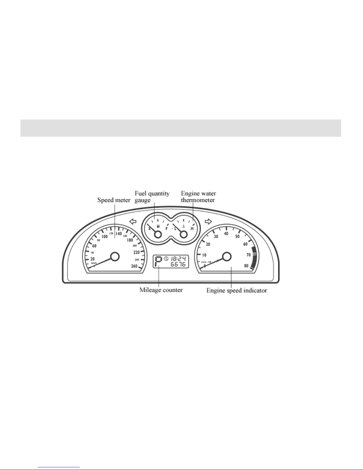
Page 31

Instrument Panel
Engine coolant temp
gauge
It displays engine coolant temperature.
Lower than L–Low temperature
range
The engine works in this range for a short
duration during warming-up process. In
this range, avoid rotation of engine at high
rate; workload of engine shouldn’t be over
high.
Please turn to Chery chartered service
station for examination & repair, if the
pointer remains in this range for long.
Between L and H–Normal
temperature range
The pointer should remain in this range in
normal running status.
The pointer may deviate from this range
when external temperature is very high
and the engine has a very workload. The
car can still run normally, if coolant
warning lamp is not ON. If coolant
warning lamp is ON for alarming, the
engine should be shut off, and the cooling
system should be checked.
Higher than H–Overheated range
When the pointer falls within the red range,
please have your car stopped in a safe way.
Turn off ignition switch and pinpoint
causes to the problem after the engine
cools off.
Beware of scalding!
Don‟t open water box
cover if the engine is still
hot. The engine can‟t be started only
when faults are well dealt with.
Note:
Installation of auxiliary front headlight in
the front of the cold air inlet under front
bumper will affect circulation of cooling
blast, disadvantageous to cooling of
engine.
The engine is easily overheated, if external
temperature is very high and the engine
works with a heavy load.
Front spoiler also directs cooling air. If it
is damaged or even ruptures due to
collision, the engine many be overheated.
Please turn to Chery chartered service
station for repair and restoration.
Page 32

Instrument Panel
Fuel quantity gauge
Fuel tank capacity: 60L
When the pointer reaches the empty oil
position (E, arrow position), there is still
10L fuel in the tank approximately.
The pointer will float to the full oil
position (F) after a car fully fuelled runs
for a distance.
The fuel that can be filled is lower than
nominal volume when the car is refueled,
due to residual oil.
Please replenish fuel when low oil level
warning indicator is ON. See ―Low fuel
level warning indicator‖.
Speed meter
It indicates current running speed of the
car.
Notice:
Speed meter is affected by tire size of the
car. Please use Chery tire of original size.
Otherwise, speed meter can’t display
vehicle speed correctly.
Mileage counter and digital
clock ( )
Gear shifting is displayed on the left of
mileage counter; overall mileage is
displayed in low right part; and time or
single-trip mileage is displayed in right
upper part.
Time is displayed in two modes, namely,
pointer type and digital type.
Switching and adjustment of time and
single-trip mileage as follows:
Switch between time and single-trip
mileage through operating tuning and reset
button on speed meter.
When mileage counter displays
single-trip mileage, press down the
tuning and reset button on speed meter
for long to set to zero.
When mileage counter displays time,
press down the running and reset
button on speed meter for long to
Page 33

Instrument Panel
adjust clock.
Engine speed indicator
It displays engine speed (Rpm).
The red area on the right of the dial
indicates maximum permissible revolution
range at working temperature of engine for
a short period after running-in.
However, it is advised that gear shift
operating rod be pushed to the next higher
gear position or move your foot away
from accelerator pedal at the latest when
the pointer reaches this area.
Notice:
To shift to a higher gear at an early time
helps save fuel and reduce running noise.
Once the engine runs unsteady, please
shift to a next lower gear immediately.
Avoid engine running at a
high rotation speed during
running-in period.
Page 34

Page 35

Audio
Chapter 3 Audio
Page 36

Audio
Note: Read carefully the instructions for audio attached, if the vehicle is not configured with the audio
system below.
Page 37

Audio
Audio Panel
1 10 11 12 13 14 17 18 15 19 16 21 20 9
4 3 2 5 22 6 7 8
Page 38

Audio
Panel description
1— Push for short for start-up; push for long for shutdown;
clockwise rotation for increase in volume; anticlockwise rotation
for decrease in volume.
2— Push the button to shift to playback of CD/MP3.
3— Push the button to shift to FM or AM.
4— Push the button to shift to playback of USB audio source.
5— LCD display.
6— Disc out.
7— AST: Auto Store.
SET: Enter into setup (push for more than 2 seconds).
8— Radio frequency/CD/MP3 audio track scanning.
9— USB interface.
10— Audio effect mode selection.
11— Low frequency scanning (radio)/fast reverse/normal playback
(CD/MP3 playback).
12— Mute.
13— High frequency scanning (radio)/fast forward/normal
playback (CD/MP3 playback).
14— Preset key 1: Push for long for radio.
RANDOM: Push for short for random playback of CD/MP3
disc.
15— Preset key 2: Push for long for radio.
16— Preset key 3: Push for long for radio.
REPEAT: Push for short for repeated playback of CD/MP3
disc.
17— Preset key 4: Push for long for radio.
:: Push for short to page up (USB/MP3 playback).
18— Preset key 5: push for long for radio.
19— Preset key 6: push for long for radio.
:: Push for short to page down (USB/MP3 playback).
20— Next/FF (USB/CD and MP3 playback).
21— Prev/FB (USB/CD and MP3 playback).
22—CD disc entrance.
Clock setup
● Push the SET button for 2 seconds at least to enter into or exit
from the menu of SET UP.
● Push the button to turn to the ―TIME‖ item.
● Push the SET button to select ―12H‖or ―24H‖.
● Push the button to pitch on the hour.
— Display example: ―16:33‖ (24H) or ―PM 04:33‖ (12H)
Page 39

Audio
— The hour option blinks.
● Push the SET key to adjust the hour.
● Push the button to select the minute.
— The minute option blinks.
● Push the SET button to adjust the minute.
— Push the button again to return to the hour option for
adjustment.
— Clock runs from the time as regulated.
● Push the SET button for 2 seconds at least to leave the menu of
SET UP.
— If the clock mode has been activated, time will be displayed
after any key is operated for 10 seconds.
Audio tuning
ON/OFF
● Push the PWR key to turn and off the audio system.
Volume
● Rotate the ON/OFF button to adjust volume.
— Please ensure that you can still hear traffic signals (air siren,
alarm whistle, etc.).
Audio/audio effect mode adjustment
● Push the SET button to enter into the audio effect mode to select
the option you want to adjust.
● Rotate the ON/OFF button to adjust setup of the audio mode
already chosen.
— BASS (low pitch) (-7, +7)
— TREBLE (high pitch) (-7, +7)
— BAL (L/R volume balance) (-7, +7)
— FRADER (F/A loudspeaker control) (-7, +7)
— LOUD (Off, Low, Middle and High) (OFF, LOW,
MID, HI)
— Enter into the audio effect mode (BASS-TRE,
JAZZ, VOCAL, POP, CLASSIC, and ROCK)
● The audio effect chosen will be displayed when the selection is
over.
● The display will return to the former operating mode
automatically after 5 seconds.
Notice: Only the audio modes, namely, ―BAL‖, ―FRADER‖ and
―LOUD‖ can be set up in an audio effect mode rather than
―BASS-TRE‖.
Page 40

Audio
Radio
Waveband
● Push the FM/AM button to select the waveband you want:
Frequency scanning (SCN)
● The frequency scanning feature enables you to listen in each
local station of current waveband for 10 seconds.
● Push the SCN button to enable/disable frequency scanning.
Automatic station search
● Push the button to tune to LF (low frequency) stations.
● Push the button to tune to HF (high frequency) stations.
● Push the or button to search for another station.
Station search sensitivity
● Switch between local and remote modes. See the ―LO/DX‖ item
of ―Equipment‖.
Manual tuning
● Switch to manual tuning (see the ―TUN‖ option of ―SET UP‖
and set it as ―MAN‖; the host will keep the mode of manual tuning
until you change it back to ―AUTO‖).
● Push the button to tune into to LF stations.
● Push the button to tune into HF stations.
Auto Store (AST)
You can store 6 most desirable stations in the waveband of FM
AST or 6 stations in the waveband of MW (AM) AST. When you
use the AST feature, the stations originally stored in the FM AST
or MW (AM) waveband will be covered.
● Push the AST button to enter into Auto Store; subsequently,
— The radio set makes a noise (―Hwa‖ sound) and then becomes
mute, and the display blinks;
— Upon completion of storage, the display will stop blinking
when you hear the same noise again.
— Stations are stored at the preset keys 1-6.
— The number of stations may be short of six sometimes.
Preset stations (1-6)
Store stations into preset keys manually.
Store 6 stations into each waveband with preset keys (1-6).
● Tune to each station you want.
● Push the preset key concerned for 2 seconds at least, and you can
hear the noise (―Hwa‖ sound) – current station will be stored into
the preset key.
Call out preset stations
● Push the preset keys (1-6) to call out the stations preset.
Switch to radio
● Push the FM/AM button to switch to the mode of radio to select
the waveband desirable.
CD/MP3 playback
CD/MP3 playback
● Push the CD button to start playback of CD/MP3 disc.
● Screen display:
Page 41

Audio
— Audio effect mode (if chosen),
— Track No. and elapsed playback time of current CD/MP3.
Track scanning
The track scanning feature enables you to hear the first 10 seconds
of each track.
● Push the SCN button to enter into track scanning.
● Push again the SCN button to exit from track scanning.
Previous/next track
● Push the or button to select the next/previous track.
For example: Push the button - T002>003; push the button -
003<T004.
● Played when pitched on.
FB/FF
● Push the or button for fast forward/backward.
● Another keystroke helps recover normal playback.
Random playback
● Push the RANDOM button to enter into the mode of random
playback.
● Another keystroke helps exit from the mode of random playback.
Repeated playback
● Push the REPEAT button to enter into the mode of repeated
current track play.
● Push the REPEAT button for long again to exit from the mode of
repeated playback.
MP3 disc list selection
● Push the D button to enter into the next list of MP3 disc.
● Push the D button to enter into the previous list of MP3
disc.
Disc ejection
● Push the button to eject the disc.
Disc maintenance
● Don’t leave your fingerprint on disc, please.
● A disc should be placed into a disc box after disc ejection to
avoid being damaged or protect against dust.
● Avoid heating or insolation of disc.
Playback in the USB mode
This audio panel keeps available a MINI USB interface. You can
have your USB memory device connected with the patch cord
furnished by manufacturer.
Document decoding description
— Support audio files: Only the files with the postfix *.mp3
(*MP3) are supported.
— Support the memory unit of 32Mbyte_4G with FLASH as
medium.
— Support mobile HD (single disc space supported only).
— Support Layer 3.
— Support the partition storage modes of FAT16 and FAT32.
— Sampling rates supported: 8K, 16K, 32K, 11.025K, 22.025K,
44.1K, 12K, 24K, and 48 KHz
— Bit rates supported: 8K, 320Kbps and VBR (MP3 PRO)
Page 42

Audio
Device attachment
● Insert a USB disk; if the connection is normal, push the USB
button to enter into the USB mode to display:
● If there is no USB disk or the USB device is pulled out, push the
USB button, and the display will be as below:
Note: It takes several to dozens of seconds of latency for
initialization of host to start MP3 due to early insertion of USB
disk according to capacity of USB disk and size of storage files.
Don’t pull out the USB disk in a hurry during the period of time.
Playback
● The following will be displayed during normal playback
— Audio effect mode (if chosen already)
— Current playback track No. and elapsed playback time.
● When all tracks in the last album are completely played, the host
will proceed automatically to the first MP3 file of the next album
in order.
Previous/next track playback
● Push the or button to select next/previous track to
display:
Page 43

Audio
Scanning playback
● Each track will be played for 10 seconds, as displayed below,
when SCN is pushed during playback.
● Return to normal playback mode when the SCN button is pushed
again.
Select previous/next album
● Push the <D > button for short to select the previous album,
and push the <D > button for short to select the next album, as
displayed below:
When a special album is pitched on, it is displayed below:
Notice:
1. Don’t pull out a USB disk forcibly when files of the USB disk
are played, because your files may be damaged in this way. You’d
better insert or pull out a USB disk when the host is shut down.
2. Don’t extend the USB connecting line provided by manufacturer
with another extension cord, because the USB protocol has high
demands for length, impedance, time delay, etc. of cables & wires.
Otherwise, the machine may fail to read the USB disk.
Setup
You can modify initialization setup to your taste:
● Push the SET button for 2 seconds at least to enter into the menu
of SETUP.
● Push the or button to select the options you desire to
modify.
● Push the SET button for option modification.
● Push the SET button for 2 seconds at least to exit from the menu
of SETUP.
The machine will exit from the mode of SETUP automatically
approximately 1 minute after your last operation.
Page 44

Page 45

Option
( or )
Option
[SET]
Usage
TIME
[OFF, 12H, 24H]
Select the clock mode required
(see ―Clock Setup‖)
RADIO
[EUROPE,
AMERECA,
LATAM, ASIA]
Select a tuner in accordance with
European, Latin, American or
Asian standards.
FM
[06, 12, 18]
Identify number of preset stations
in the mode of FM.
MW (AM)
[ON, OFF]
Select ―OFF‖ to close MW (AM).
Note: LW (ON, OFF) is displayed
only when the EUROPE option is
set up in the status of RADIO.
MW (AM)
[06, 12]
Identify number of preset stations
in the mode of MW (AM).
TUN
[AUTO, MAN]
Select automatic tuning or manual
tuning.
SRCH
[LO, DX]
Select ―LO‖ when you would like
to search for intense frequency
only in automatic tuning.
CD
[-2, -1, 0, +1, +2]
CD play volume, relative to tuner
BEEP
[-2, -1, 0, +1, +2]
Select and confirm the volume of
the ―Hwa‖ sound.
LOG
[OFF, ON]
Select ―ON‖ to assure that
automobile engine still remains
effective after one hour.
Notice: Set up initial volume by means of tuning the volume
button in the mode of SETUP. For example, the volume is higher
than reference volume when the audio is turned off, and the initial
volume is taken as reference volume when the audio is restarted.
For another instance, the volume is lower than reference volume
when the audio is turned off, and the initial volume is still as
reference volume when the audio is restarted.
Inspections prior to maintenance
When you feel that some functions of the automobile audio fail,
please read carefully the operating instructions of the manual
before sending it for repair and then make a detailed check against
the table below. This will be of help to your handling of faults.
Phenomenon
Possible causes and solutions
General conditions
The host idling, no
display
Take out the host from the instrument and inspect the
host and fuse and adapter connector of automobile.
The host working,
without noise or
with very little
noise
Volume up;
check the balance position of loudspeaker, back and
forth, right and left; check antenna and adapter
connector
The machine body
slightly heating
The machine generates heat regularly.
Radio
Bad effect of
reception
Inspect whether the antenna is well connected (whether
the cathode is earthed); inspect whether the aerial
amplifier in the vehicle is damaged; employ manual
tuning if signals for desirable stations are too weak.
USB playing
Some audio files
Please determine whether the file is a MP3 file. The
Page 46

1. It is normal for a disc not to be read or that the sound is
interrupted when a car runs on bumpy roads.
2. Please use original disc. Normal quality warranty
doesn’t cover the faults incurred due to use of pirated
software.
that can’t be played
machine supports MP3 format only.
Unsteady volume in
MP3 playback
Because MP3 songs have wide sources and are lacking
in a unified standard, it is possible that the set volumes
vary much when MP3 songs are compressed. In such a
case, tune volume yourself.
Failure in
displaying such
information as
singer/track/song
name
This system doesn’t support display of ID3
information.
Interruption of
music in playback
Possibly arising from different compressed formats of
songs
Unable to read
songs in mobile HD
Please confirm that there is only one disk partition of
HD. This system doesn’t support multiple disk
partitions.
If no less than two disk partitions have bee divided,
e.g., E disk and F disk, or more disk partitions, the
machine will be unable to read MP3 songs from the
HD. If you want to use it, please combine all disk
partitions into a single disk partition on your computer.
Unable to read
songs from a
memory device
Please confirm on your computer that the storage
partition mode of your memory is FAT16 OR FAT32.
If it is not, set the mode as the one compliant with
requirements.
Unable to read MP3
songs from
all-in-one USB
commutator
This system supports the commutator with a single
USB port only.
Sound
Sound blasting/noise may be caused by the equipment
blasting/noise
or noise when original MP3 files are recorded. Please
confirm with other (media) players whether it’s the
problem of the machine itself.
CD
―NO CD‖ displayed
and ―Hwa‖ sound
available
No CD disc placed
―CD ERROR‖
displayed and
―Hwa‖ sound
available
CD disc reversely placed, damaged or smirched; CD
disc type erroneous
Volume distortion
in playback
Disc damaged or smirched
● Please send the machine to a maintenance point for repair if
faults can’t be removed still.
Don’t disassemble the machine randomly to make a repair by
yourself.
Page 47

Air Conditioning System
Chapter 4 Air Conditioning System
Page 48

Page 49

Air Conditioning System
Air conditioning system
Air renewal
External air enters into the vehicle
through air inlet before windshield.
Please keep the air inlet beneath
windshield glass clear of snow deposit,
tree leaf, etc. to ensure regular and
effective heating and ventilation.
Foul air within the vehicle is dissipated
from the exhaust port in side lining of
baggage compartment.
Notice:
Don‟t obstruct exhaust ports when
baggage is loaded.
Page 50

Page 51

Air Conditioning System
Page 52

Page 53

Air Conditioning System
Air cleaner
Air cleaner ensures that toxic particles
(such as pollen, industrial dustfall and
road dust) contained in air are removed by
filtration before the air flows into the
vehicle.
It is suggested that fans be closed down to
avoid accumulation of wax on air cleaner
when the car passes through an automatic
car washer.
Air cleaner should be replaced according
to driving environment and customer
habits.
Air flow distribution
Air flows and directions may be adjusted
through buttons on air conditioning
control panel and control devices of side
air outlet and central air outlet.
Central air outlet and side air
outlet
To be adjusted as required
Maximum air flow
Maximum air flow can flow to pedestal
area or windshield glass when central and
side air outlets are shut off.
Page 54

Page 55

Air Conditioning System
Electric controlled automatic air conditioning system ( )
Page 56

Page 57

Air Conditioning System
1. Air conditioning display panel
Note: Some symbols for air conditioning system are displayed in the figure above. When air conditioning system runs, some symbols may
not appear. Relevant symbols only appear in relevant operating modes. Thereby, they represent current operating modes of air conditioning
system. We’ll make an introduction below.
Page 58

Page 59

Air Conditioning System
2. Internal air circulation
button
Push down or up internal air circulation
button to switch between external air
intake and internal air circulation. In the
mode of internal air circulation, the
internal circulation symbol will be
displayed.
Fan voltage is reduced by 1V (4.9~10V)
when internal air circulation is switched to;
when external air intake is switched to, fan
voltage is restored.
In high temperature weather, turn on air
conditioning and push down internal air
circulation button to rapidly cool the air
inside the vehicle. Internal air circulation
mode may be also used to keep off odor
outside.
When windshield defrosting is
selected, the button will not function; and
thus, internal air circulation mode can be
set.
3. Fan rotation speed
control button
Push down the triangle-up button to
improve rotation speed of air blower to
increase wind rate; push down the
triangle-down button to decrease rotation
speed of air blower to reduce wind rate.
Fan rotation speed can be divided into six
levels for manual adjustment, gradually
increased from minimum wind rate (Grade
1) to maximum wind rate (Grade 6).
Air conditioning control system will adjust
fan rotation speed automatically when the
mode of AUTO is chosen to keep
temperature at the set value. In the mode
of AUTO, fan rotation speed may be
adjusted manually. When wind rate is
reduced to Grade 1, please exit from the
mode of AUTO; when wind rate is
increased to Grade 6, please exit from the
mode of AUTO, too.
4. Temp control
knob/external temp
display button
This button is used to adjust air
temperature, which may be regulated in a
step-by-step way (with each step as
0.5℃).
Right-handed rotation: temperature
rise, 0.5℃ increased every cascade
rotated.
Page 60

Page 61

Air Conditioning System
Left-handed rotation: Temperature fall,
0.5℃ reduced every cascade rotated
The temperature value set will be
displayed on the AC (air conditioning)
display panel.
The standard value suggested is 22℃.
Temperature may be set between 18℃ and
32℃ with switch. LO will be indicated for
temperature lower than 18℃ and HI for
temperature higher than 32℃.
Left-handed rotation may increase cooling
capacity when the cooling system works.
In the position of ―LO‖ (lower than 18℃),
the system will be set to the status of low
temperature; in the position of ―HI‖
(higher than 32℃), the system will be set
to the status of high temperature instead of
the temperature when air conditioning is
ready.
When the knob is pushed down, the set
temperature value as displayed will be
replaced with external temperature value
for a short duration, while the external
temperature symbol will be also
displayed. The temperature value set will
be re-displayed after three seconds and
meanwhile, the external temperature
symbol will disappear. During the
period when external temperature is
displayed, rotation of the knob won’t alter
the temperature value set.
5. AUTO mode switch
When the button is pushed down, the
control system will adjust automatically
position of air mixture door, air
conditioning status, rotation speed of fan
and external air intake or internal air
circulation to regulate temperature inside
to the value set, according to the
temperature set, external temperature
signal, and variance of internal
temperature signal.
The automatic running symbol
will be displayed.
In the mode of AUTO, the initial status of
air blowing is defaulted as the mode
toward face and feet. Air blowing mode
may be changed via the MODE button.
The AUTO and MODE buttons are
mutually independent.
The defrosting function is correlated with
windshield wiper signals. That is, air
conditioning is automatically set in the
mode of defrosting (with wind rate, etc.
unaltered) when the windshield wiper is
initiated.
Operating mode of compressor is
determined by the temperature set. If the
temperature set is higher than 28℃, the
compressor won’t pull in.
The system will switch to internal
circulation automatically, when any of the
three conditions below are met:
Air conditioning system starts running
(i.e., compressor is initially started
up).
The driving speed 10Km/h lasts over
10s.
The vehicle is in a state of rest.
The system will runs according to the
operating mode or interface set by user
last time.
Page 62

Page 63

Air Conditioning System
6. Air conditioning OFF
switch
Turn off the air conditioning system.
The system will enter into the state of OFF
when the button is pushed to close down
the display. Meanwhile, actuating
mechanisms will be shut down fully.
Push the AUTO button or A/C button or
the defrosting button to automatically start
the system, when the system is in the state
of OFF. The system will enable the
operating mode or interface set by user
last time.
7. Air blowing mode switch
Change the air blowing mode once when
you push the button each time. Repeatedly
push the button to switch between the
three modes below to display the
following three symbols:
Towards feet; air output fully to foot
space.
Towards face; air output fully to the
area at the height of face.
Towards feet and face; air output
partially to foot space and partially to
face area.
8. AC cooling switch
Push down the ―A/C‖ button to start up the
cooling system; meanwhile, the ―Snow‖
symbol will be displayed.
The cooling system works only when the
following conditions are met:
Engine in running order.
Ambient temperature higher than -1℃.
Air blast switch at gear 1-4.
With the cooling system working, not only
the temperature inside could be reduced,
but also humidity of the air flowing inside
could be reduced. Thus, customers inside
will feel more comfortable, and vehicle
windows avoid fogging.
Page 64

Page 65

Air Conditioning System
To achieve the best cooling effect, all
vehicle windows should be closed when
the cooling system works.
9. Windshield glass
defrosting/defogging
switch
This switch is used for windshield
defrosting. Push down the button to
change the air intake mode into external
air intake. The cooling system will be also
started up. All air output will flow to
windshield glass and side
defrosting/defogging outlets.
The windshield defrosting symbol
will be displayed.
Cost-effective operation of air
conditioning system
Fuel consumption will be
increased because air
conditioning compressor
consumes engine power. To save energy
and reduce fuel consumption, turn off the
air conditioning system when air
conditioning is not necessary. It is
suggested that vehicle windows or doors
be opened to dissipate hot air when the car
parked has its interior space highly heated
due to insolate. This helps improve
cooling effect and reduce fuel
consumption.
Don’t open the air conditioning system
during running when windows keep open.
General description
The air conditioning system absorbs
moisture of air, which will be condensed
into water on an evaporator. Therefore, a
little amount of water may appear beneath
the vehicle when your car stays
temporarily.
Heating effect depends on coolant
temperature of engine. Thereby, the
heating system functions effectively only
when the engine is in warm-up mode.
It is suggested that air blower be placed at
low-speed gears during running to avoid
glass misting.
It is suggested that human body be
protected from direct cooling air.
Brief operating instructions
for automatic air conditioning
system in hot days
1. Push ―AUTO‖.
2. Push the ―Internal circulation button‖
to select internal air circulation mode.
3. Set the temperature to ―LO‖.
4. Re-set temperature to personal
comfort level after temperature is
reduced.
Tip:
Please keep internal air circulation when
automatic air conditioning system is used
in hot days to achieve best cooling effect
and protect against external odor.
Page 66

Page 67

Air Conditioning System
Failure recovery
Cooling system idling
Ambient temperature may be lower
than -1℃.
A fuse may blow.
Please check the fuse. Replace it when
necessary. If a failure is not caused by fuse,
turn off the AC cooling system (with the D
―AC‖ button). Turn to professionals for
inspection.
Cooling efficiency weakened
Once cooling efficiency is found abated
and wind rate reduced, please turn off the
system and turn to professionals for
inspection.
Rear window
defrosting/exterior
rear-view mirror heating
Rear window defrosting control switch is
set at central console of the instrument
panel.
Light ice and mirage on rear window
could be removed, when the defrosting
and heating button is pushed down.
Rear-window defrosting & heating device
works only when the igniting circuit is put
through. Push down the electrical heating
button to enable/disable the heating
system. When the heating system is put
through, the indicator lamp will light up to
display heating.
Notice:
Once rear window is transparent, cut
off the heating system to reduce current
consumption and save fuel.
Rear window defrosting will be
automatically over when defrosting lasts
10 minutes or ignition switch shifts to the
position of OFF. When defrosting lasts
less than 10 minutes, please push the
defrosting button again if you want to stop
rear window defrosting in a manual way.
To initiate rear window defrosting will
also enable exterior rear-view mirror
heating.
Page 68

Page 69

Air Conditioning System
Manual air conditioning system ( )
Air conditioning control panel
Page 70

Page 71

Air Conditioning System
Temperature regulation knob
Temperature regulation button is used to
control temperature of the air blown out of
ventilator scoops. The knob is rotated to
select appropriate temperature.
Blue range: Cooling
Red range: Heating
Cooling button
When ambient temperature is higher than
4℃, engine is running, wind speed
adjustment button for air blower is set at
any of the 4 gears, and air conditioning
system has a normal pressure, the
indicator lamp will be ON to start up the
air conditioning compressor for air
conditioning and cooling after the button
is pushed down. Push the cooling button
again to disenable air conditioning.
When the cooling system works, not only
the temperature inside can be reduced, but
also temperature of the air from outside
can be reduced, to make passengers more
comfortable and avoid fogging of vehicle
windows.
All vehicle windows should be closed to
achieve best cooling effect, when the
cooling system works.
Notice: Air conditioning enabled will
make engine over-heated when the car
climbs up a long slope or comes across
traffic congestion. Observe water
thermometer, and turn off the air
conditioning system if the engine is
over-heated.
Air conditioning compressor will consume
engine power when air conditioning is
used for cooling; thus, fuel consumption
will be increased.
Wind speed adjustment knob
for air blower
Wind speed adjustment knob for air
blower is used to control wind speed of air
blower (4 gears in total). Wind speed is
adjusted with air blower. To improve
comfort, air blower may be started up
during running.
Page 72

Page 73

Lamp Control
Internal/external air circulation button
To switch to external fresh air mode or internal air circulation mode is achieved through this button.
External circulation
External air into the car is used for normal ventilation, heating and cooling.
Internal circulation
Internal air is circulated inside the car. Indoor circulation mode is used in dusty environment or in the case of waiting for pass
permission (indicated by green light) in urban area, and for rapid cooling or heating of indoor air.
Notice: Internal circulation mode can be used only for a short duration, because continual use of internal circulation mode produces
stuffiness inside and hazing of vehicle windows.
Airing mode control button
This button is used to choose direction of air flow. There are five options inclusive of ―Towards head‖, ―Towards heard and feet‖,
―Towards feet‖, ―Towards feet and for defrosting‖ as well as ―Defrosting‖.
Page 74

Lamp Control
Refer to the airing mode introduction contained in the part ―automatic air conditioning‖ for details of each exact mode of air flow
direction.
Air conditioning system maintenance instructions
If air conditioning system is not used for a month or a longer period, curb idling of engine with air conditioning enabled is necessary
even in winter. The air conditioning system should be started up once every month at least and for several minutes in order to keep
approximate lubrication and tightness of air conditioning compressor to extend service life of the system.
Page 75

Lamp Control
Chapter 5 Lamp Control
Page 76

Page 77

Lamp Control
Lamp Control
Please abide by related traffic regulations
when using the following illuminating
equipment.
Headlamp Switch
OFF – Turn off the external lamp.
Gear 1 will light the parking
lamp/position lamp, the component
illuminating lamp such as instrument and
switch, and license plate lamp.
Gear 2 the front headlamp
will light (low beam or high beam).
Note:
Only when the ignition switch is turned
on, the headlamp can work. When the
engine is started or the ignition switch is
turned off, the headlamp will be off
automatically.
Headlamp High/Low
Beam Selector Switch
Under the condition that the lamp is
turned on, pull the handle towards the IP
direction to shift into the high beam lamp
after passing the force application point.
When the headlamp high beam is turned
on, the high beam indicator in the
instrument will light. Pull the handle
towards the steering wheel direction to
return to the original position so as to
resume the low beam lamp.
Flash of Front
Headlamp
When you need the flash of headlamp
during driving, you only pull the handle
towards the steering wheel direction to
the force application point and then
release the handle. Repeat such action to
flash the headlamp consecutively.
The headlamp will light
automatically.( )
Page 78

Page 79

Lamp Control
The headlamp switch with auto turn-on
system has the AUTO position; when the
ignition key is turned to the ON position,
the headlamp switch will be on the
AUTO position, and when the ambient
light is weak, the headlamp will light
automatically (if the ambient light is
relatively strong, the headlamp won’t
light).
Adjustment Switch of
Electrical Regulated
Headlamp ( )
The adjustment switch of electrical
regulated headlamp is located on the left
lower corner of the dashboard.
Such switch has four gears of 0, 1, 2, and
3. The adjustment of four gears can
adjust the light type of the electrical
regulated headlamp.
Front/Rear Fog Light
Switch
The front fog light and the rear fog light
are located on the central console of the
dashboard, under the audio control panel.
When the headlamp switch is at gear
1position, press the front fog light switch
to turn on the front fog light, but it can’t
turn on the rear fog light directly.
When the headlamp switch is on the gear
2 position, press the front and rear fog
lamp switch, the front and rear lamps can
turn on at the same time; also the rear fog
lamp can turn on only by pressing the
rear fog lamp switch.
Use fog lamps correctly
according to the traffic rules.
When the front fog light is turned on, the
front fog lamp switch inner indicator will
turn on.
The front fog light should only be used
under the conditions that severely
affected the visibility, such as fog, snow
or rain.
When the rear fog light is turned on, the
rear fog lamp switch inner indicator will
turn on.
Since the rear fog light is very dazzling,
it's allowed to be used only under the
conditions with poor visibility.
Page 80

Page 81

Lamp Control
Turn Signal Lamp
The turn signal lamp will operate only
when the ignition switch is turned on.
Left turn signal lamp – pull the handle
downwards.
Right turn signal lamp – pull the handle
upwards.
When the turn signal lamp is turned on,
the turn signal indicator will also flash.
Lane change signal lamp
Pull the handle upwards and downwards
to the force application point and the
relevant turn lamp will flash, and
meanwhile the turn signal lamp in the
dashboard will also flash.
Dashboard illumination
dimmer
During the working period of the
external lamp, use the illumination
dimmer to adjust the instrument
illumination.
Interior Front Ceiling
Lamp
Press the left switch: The left
illuminating lamp will keep illuminating.
Press it again to turn off the lamp.
Press the right switch: The right
illuminating lamp will keep illuminating.
Press it again to turn off the lamp.
Page 82

Page 83

Lamp Control
Interior Rear Ceiling
Lamp
The OFF position: The illuminating lamp
turns off.
The ON position: The illuminating lamp
will keep illuminating.
The middle position (door control
position): The interior lamp will light
when the door is opened; the interior
lamp will keep illuminating for 8s when
the door is closed so as to seat passengers
safely.
Luggage Boot
Illuminating Lamp
Such lamp will light when the luggage
boot cover is opened (This lamp is not
subject to the control of ignition switch).
Please close the luggage boot cover
securely after parking.
Also set the lamp in the OFF status, that
is, the lamp won’t light when the boot
cover is opened. Therefore, press the
trigger switch to the locking position.
The lamp can light by releasing the lamp.
Sun visor vanity mirror
The vanity mirror lamp will light once
the vanity mirror cover is opened.
Front Sill Lamp and Key
Cylinder Lamp
When the front door is opened, the key
cylinder lamp and the front sill lamp will
both light.
The front sill lamp is located on the inner
trimmer panel between the two front
doors. If the door is opened, whatever the
ignition switch is on, the sill lamp will
light in the sill area and also guide the
driver. When the door is closed the sill
lamp will be off.
The key cylinder lamp is located around
the ignition key cylinder. When each
front door is opened, the lamp will light
so as to assist the driver to insert the
ignition key, or such lamp will turn off
when the key is turned to the ―ON‖
position.
Danger Flash Alarm
Lamp Switch
This alarm lamp should be used only
under emergent conditions so as to alarm
the following vehicles that this vehicle
has trouble or danger. Press this switch to
turn on/turn off this system. The danger
flash lamp is operational when the
ignition switch is turned off.
Page 84

Page 85

Lamp Control
The indicator on the switch will flash
after the alarm lamp is turned on.
Meanwhile, if the ignition is turned on
the turn indicator lamps of the combined
instrument will also flash.
Note: When the vehicle runs in the rain,
the vehicle glass becomes cold
dramatically and the temperature around
the glass also becomes lower, so the
moisture in the air will agglomerate and
be attached to the insides of the glass to
form dew. The theory of the dew inside
the headlamp cover is the same as it.
That is, the moisture in the air increases
as the temperature becomes high. If the
temperature becomes low, the moisture
will agglomerate and form dew
commonly called fog phenomenon.
When the lamp has moisture and the high
or low beam lamps are turned on within
30 minutes, the moisture will gradually
start to disappear; after one hour, the
moisture naturally disappears, that is
normal phenomenon, otherwise, it maybe
has water insides. If so, please contact
Chery authorized service station for
check and service.
Check the headlamp
installment carefully when replacing
bulbs to make sure the correct
installment and good seal! Otherwise
the headlamp maybe has water or dust
insides!
It is strictly prohibited
flushing the engine compartment via a
water-cannon, especially lamps. As
the pressure of the water-cannon is
too high, it may cause lamps parts to
loosen or drop, vent hole and harness
connectors to become damp, and the
lamps have water or moisture insides,
which can’t dissipate for a long time.
At last, the dew forms, very serious.
Page 86

Page 87

Operation and Adjustment of Interior Devices
Chapter 6 Operation and Adjustment
of Interior Device
Page 88

Page 89

Operation and Adjustment of Interior Devices
Interior Device Operation and Adjustment
Page 90

Page 91

Operation and Adjustment of Interior Devices
Steering lock/ignition
switch
Combined-type steering lock/ignition
switch has the positions of key below:
LOCK–Ignition switch is turned off and
the steering wheel is locked.
To lock the steering wheel up, please
rotate the steering wheel when the key is
pulled out until you hear the gripping
sound of the steering wheel.
ACC–Steering system unlocked; electric
fittings are put through and the small
electric appliances as audio and indoor
lamp are operable, but ignition switch and
primary electric loop should be all
switched off.
If it is impossible or very difficult for the
key to turn from the LOCK position to
this spot, please rotate the steering wheel
slightly to unloosen the lockup mechanism
of the steering wheel.
The key to the ignition switch shouldn’t be
placed here for long to avoid electric
power exhaustion of accumulator cells.
ON–The ignition circuit is put through and
all electric loops can start working.
Warning indicator and indicator lamp light
up. This is the normal position of key in
driving and the position necessarily
selected when the vehicle is towed and
trailed.
START–Starting motor is put through to
start engine up.
Front headlamp and electrical equipment
of high power consumption are all
switched off when the locking hole is at
this position.
The device against redundant startup is
installed in ignition switch. Once engine
runs, the device will protect starter from
false startup to avoid damages to the
starter and engine flywheels.
In cause of unsuccessful startup, the
ignition key must be rotated to the position
of LOCK prior to restarting and then
rotated to this position. After startup,
loosen your hand, and the key will bounce
back to the position of ON.
Loosen your key
immediately once the
engine is started up.
The steering lock will be initiated to lock
up the steering wheel when the key is
pulled out from ignition switch.
Don‟t rotate the key to the
position of LOCK when the vehicle
moves.
Page 92

Page 93

Operation and Adjustment of Interior Devices
Steering wheel
adjustment
In order to drive your car in a safe and
comfortable way, overhang and height of
the steering wheel may be adjusted
sometimes. In this case, the arresting lever
on the shield of steering post may be
raised towards the steering wheel. Then,
the steering wheel can slide up and down
and be adjusted to any position. When the
steering wheel is adjusted into place,
loosen the arresting lever and lock up the
position of the steering wheel.
Don‟t adjust the steering
wheel in running.
Loudspeaker
Loudspeaker buttons are located at both
sides of the steering wheel, as indicated by
arrows above.
Windshield wiper and
washing system
Check whether wiper blades
are frozen on windshield
glass in cold seasons before
windshield wiper is used. If they‟re
frozen on windshield glass, they
can‟t be used unless they‟re melted.
Otherwise, wiper motor will be
easily damaged.
To operate windshield wiper will
also damage wiper motor if
windshield glass is covered with
obstacles including snow, etc.
Obstacles must be removed before
windshield wiper is operated.
Don‟t operate windshield wiper on
dry windshield glass. Otherwise,
glass may be scratched and
permanent damages are possibly
incurred to wiper blades.
Page 94

Page 95

Operation and Adjustment of Interior Devices
The following features are enabled only
when ignition switch is put through.
Interval wiping( )
If windshield wiper is not set as automatic,
―AUTO‖ indicates interval wiping; move
the control lever upwards to ―AUTO‖
from ―OFF‖ to achieve interval wiping
(the knob may be rotated to adjust time
interval during interval wiping: the wider
the pattern indicated by arrow is and the
larger the area is, the interval time will be
much longer; the narrower the pattern
indicated by arrow is and the smaller the
area is, the interval time will be much
shorter).
Automatic wiping( )
If automatic wiping is configured,
―AUTO‖ indicates automatic wiping;
windshield wiper will work automatically
in rainy weather, when the control lever is
moved upwards from ―OFF‖ to ―AUTO‖.
The windshield wiper will stop working
automatically when there is rainfall in
small amount or no rain.
Normal wiping
Move the control lever upwards from
―OFF‖ to ―LO‖ by two levels.
Wiping at a high rate
Move the control lever upwards from
―OFF‖ to ―HI‖ by three levels.
Water spray switch
Pull the switch handle to the steering
wheel and hold it on. Cleaning liquid will
be poured out from the water jet before
windshield. The water jet will stop water
injection when the handle is loosened;
however, the windshield wiper still works
for a little while thereafter.
Page 96

Page 97

Operation and Adjustment of Interior Devices
The duration for water
injection shouldn‟t exceed
10 seconds, but no
operations are allowed to be done
if no cleaning liquid is available in
accumulator tank.
Interior rear-view mirror
The regulating stem may be pulled
backwards to adjust the angle of rear-view
mirror for reducing glare in night driving.
Window visor
Cosmetic mirror available on window
visor may be opened for use; window
visor may be released from fixation clamp
and rotated to side window.
After window visor is rotated to side
window, extension board may be pulled
aside to enlarge the scope of sunshade.
Sunglass box
Push and open it.
Rear manual blind
The blind may be rolled out through the
pull handle in the middle. Then, fasten the
buckles on hangers at both sides of ceiling.
Page 98

Page 99

Operation and Adjustment of Interior Devices
Rear electric blind switch
( )
This switch is located at central console
behind the shift bar.
If a rear electric blind is mounted on a car,
push this button to close the blind, and
push the button again to open it up.
Control switch on car
door
Electric exterior rear-view
mirror ( )
Electric rear-view mirror is adjusted with
the regulating switch on driver’s side car
door. The regulating switch can’t start
working only when ignition switch is
turned on.
Rotate the regulating switch into place in
an anti-clockwise way to adjust left
exterior rear-view mirror; rotate the
regulating switch into place in a clockwise
way to adjust right exterior rear-view
mirror.
When the regulating switch is rotated into
place leftward or rightward, it may be
pushed to learn forward, backward,
leftward and rightward to adjust the
position of mirror up, down, left and right
respectively. Rotate it to the central
position when the mirror position is well
adjusted.
Folding electric exterior
rear-view mirror ( )
Rotate the regulating switch of rear-view
mirror by 180 degrees; push the switch
leftward to fold the rear-view mirror and
push it rightward to unfold the rear-view
mirror.
Page 100

 Loading...