

Page 1

Preface
ADVICE
User’s Manual clarifies the agreement between Chery
Automobile Co., Ltd. and the User on the product quality
warranty responsibility and the establishment and termination of
after-sales service rights and responsibilities. Please read this
User’s Manual carefully before using our products.
User’s Manual for Chery Riich 2 series
Sincere congratulations on y our own of one Chery Riich 2! Also, with great app reciation on your great favor on our company and our
products.
The personnel of Chery authorized service station are trained with good professional trainings, who will sincerely provide you with the top
quality service.
Chery Riich 2 features advanced technology and prominent performances. Your choice of Chery Riich 2 will prove that you have extra-hi gh
requirements on the vehicle performance and design.
Please read this manual car efully, since the informat ion contained in this manual can let y ou underst and how t o operate and maintain y our
vehicle properly so as to achieve the driving pleasure to the maximum extent.
This user’s manual applies to the Chery Riich 2.
Chery Automobile Co., Ltd.
Page 2

Preface
This manual is established based on the
detailed conditions of Riich 2 vehicles
manufactured by Chery Automobile Co.,
Ltd., which only applies to the Riich 2
vehicles manufactured by Chery
Automobile Co., Ltd.. This manual
includes the latest information up to the
date when this manual is printed. Chery
Automobile Co., Ltd. will be wholly
responsible for the modification and
exp lanation of this manual and reserved
the rights for product replacement after the
print of this manual without any prior
notice. So me pictures in t his manual are
illustrations for reference only. The real
art icle should take p recedence in cas e of
any conflict be t ween t he p ict ur es and t he
real articles.
This manual is the main evidence for
vehicl e qualit y w arranty. Please keep this
manual in your vehicle so that it’s
available whenever you need it. When you
resell this vehicle, please hand over this
manual and all the do cumentation attached
with t his vehicle t o the new owner so that
they are available whenever the new
owner needs them.
Special Statement
Please make sure to read this manual,
especially the chapter “Quality warranty
service” before using this product,
otherwise y ou may have no right t o take
the service due to your improper usage.
Chery Automobile Co., Ltd. (hereafter
referred as “Our Company” or “Chery
Company”) defined the technical
maintenance regulations of the new
vehicle run in and of maintenance at
various stages for t he products, including
the first 5,000 km maintenance. Please
make sure to abide by the above
regulations since the above defined
maintenance is vital to the safety operation
and the maintaining of good running
conditions of your vehicle.
Your claim right will be forfeited in case
of the failure of your vehicle or vehicle
parts arising from t he abuse, negligence,
improper use, the maintenance not in
accordance with the specified
mileage/period, or the warranty evidence
not s igned or s t amp ed in accord ance wit h
the requirements, or any unauthorized
refit/attachment. Therefore, any direct or
indirect warranty app lication thereof will
not be accep ted by t he Chery authorized
service station.
Any problems of Our Company’s products
during use must be overhauled by the
Chery authorized service station. During
the overhaul process, Chery authorized
service st ation is ent itled t o decide ba sed
on the conditions t o perform the repair by
means of repair or the replacement of
equivalent parts.
If you encountered anything unclear
during the careful reading of t his manual,
Chery Company and Chery authorized
service st ation will giv e you t he detailed
exp lanat ion. Also, the p recious advices of
vast users are highly welcomed.
Chery Automobile Co., Ltd. reserved all
copyrights of this manual
Wish you pleasant driving!
Page 3

Chapter 1 Summary
Before reading this User’s Manual, you
should understand following things. ..........2
Equipm ent Sc ope ........................................ 2
Alarm Symbols within This Manual .............. 2
New Vehicle Inspection ................................3
Run in of New Vehicle ..................................3
Run in Regulation within 1,000 km ................. 3
Run in Regulation from 1,000 km to 1,500 km
Notice during Run in Period
“One-To-One” Service .................................4
Vehicle Delivery Inspection Certificate ......5
Chery Vehicle Sale & Delivery Sheet
“One-To-One” Counseling Service Card
(Service Station)
The following items should be confirmed by the
use r.
“One-To-One” Counseling Service Card .10
(Customer) ..................................................10
T able of contents
...........................1
Common Vehicle Symbol Instruction ...... 11
Chapter 2 Driving ............................ 14
Start ............................................................. 15
............................................................................. 3
............................ 3
Engine Control System Self-adaptive
Function ...................................................... 17
.........7
...........................................9
..................................................................... 9
Engine RPM Limit
Engine stall ................................................. 17
Brake
Preface
The following items should be confirmed by the
user:
Pr epar at ion bef or e S t ar t ............................. 15
Saf ety Not ic e ........................................... 15
Befor e Vehicle Star t .................................. 15
Engine S tar t ............................................. 16
Caution of Vehic le Exhaust Fume ............... 16
Vent ilation Not ice ..................................... 16
Dual-Circuit Brake Syst em ........................ 18
Bra ke Liqu id leve l a lar m ........................... 18
Operation Ins tr uction of Brake System ........ 18
Brake Boos ter : ......................................... 19
................................................................... 10
.................................... 17
........................................................... 18
Page 4

Preface
Ant i-loc k Brake Sys tem ( ABS) ( ) ............ 19
Reaction of ABS ............................................... 19
Braking by taking Advantage of ABS
A B S Self-Examination
Handbrake ............................................... 21
Shift .............................................................21
Steering
Paddling ......................................................22
Three-Way Catalytic Co nverter ...............22
Drive the Vehicle Equipped with a Catalytic
Converter ................................................ 23
The following conditions should be avoided: 23
Parking ........................................................23
Chassis Protection .................................... 24
Fuel Consumption ......................................24
The fuel consumption is influenced by the
following factor s : ..................................... 24
Essentials for Fuel- Saving Driving and
Environmenta l Protect ion: ......................... 25
Radiato r Fan ..............................................25
Instruction ............................................... 25
Chapter 3 Introduction of Vehicle
Functions & Instruction of Designations
............................................................ 27
........... 20
.................................... 20
.......................................................21
I. Introduction of Vehicle Functions ..... 28
Steering wheel lock/ignition switch ............ 28
Horn ....................................................... 29
Windscreen Wiper & Cleaning S ys tem ........ 29
Intermittent Wip ing .................................. 30
Nor m al W ipi ng ........................................ 30
High Speed Wiping ................................... 30
Water S pr ay Sw itc h .................................. 30
Interior Rearview Mirror ........................... 30
Exterior rearview mirror ............................ 31
Sun Visor ................................................ 32
Control Switches on Front Left Door .......... 32
El ectrical Window (
Front left door .................................................. 32
Front Ashtray, Cigarette Lighter ................. 33
Headlamp sw itch ...................................... 34
Conversion of high beam/ dipped headlight . 34
Flic ker of Headlamp ................................. 34
Sw itches of Front & Rear Fogs .................. 34
Turning Indicator ..................................... 35
Interior Front and Middle Ceiling Lamps ..... 35
Danger Alarm Lamp S witc h ....................... 35
) ............................ 32
Page 5

Preface
Braking Lamp .......................................... 36
Revers ing Lamp ....................................... 36
Sound System .......................................... 37
A/C System ............................................. 41
Central vent hole ...................................... 43
S ide a ir out let ........................................... 43
Defros t air outlet of front windscreen .......... 43
Ceiling Air Outlet and Control .................... 44
Control Panel ........................................... 45
Ventilation & Warm Air ............................. 45
Blow e r Switch ......................................... 46
Internal/ external circulation c ontr ol lever .... 46
Airflow Distribut ion Switch ....................... 46
A/C System ............................................. 48
II. Instruction of Designation ...........51
Ins trum ent Panel ( ) ................................ 51
Warning Dev ice ........................................ 53
Low Fue l Level Alarm Lamp ..................... 53
Par king br ake alarm lamp .......................... 53
Braking s ystem alarm lamp ........................ 54
Parking/position indicator lamp .................. 54
Saf ety belt alarm lamp ............................... 54
Engine def ect alarm lamp .......................... 55
High beam ind icator lamp .......................... 55
Turning signal ind icator lamp ..................... 55
Air bag a larm lamp ( ) ........................... 55
Low engine oil pressur e alar m lamp ............ 56
Battery charge indic tor lamp ...................... 56
Coolant tempe r ature/leve l alarm lamp ......... 56
Door not close alarm lamp ......................... 57
EPC defect alarm lamp .............................. 57
Braking d isc a larm lam p (
Maintenance indicat or lamp ....................... 57
Engine coolant tem per at ur e ga uge .............. 57
Fuel gauge ............................................... 58
Speedometer ............................................ 59
LCD ....................................................... 59
Engine t achom eter .................................... 60
) ..................... 57
Ch ap ter 4 Safety ............................... 61
Door Lock & Anti-theft ............................. 62
Key ........................................................ 62
Door Lock ............................................... 62
Sliding Door ............................................ 63
Central Contro l Lock (
Back Door ............................................... 64
Release Rod of Filler Cap ......................... 64
) ......................... 64
Page 6

Preface
Open Engine Bonnet ..................................65
Remote Control System with Anti-Theft
F u nct ion ( ) ...............................................66
Door Lock & Unlock ................................ 66
Alarm ..................................................... 66
Remote Cont r ol ler Bat ter y Repl ac em ent ...... 67
Electroni c Anti-theft System ...................... 67
Seat & Safety Protection ...........................68
Seat ........................................................ 68
Correct Sitti ng Posture .............................. 68
Ad justment of Front Seats .......................... 68
Ad justment of Middle Seats ....................... 69
Adjust ment of Rear S eat s .......................... 69
Headrest .................................................. 69
Adjusting method of headrest: ....................... 69
Removing and assembling method of headrest:
Folding of Middle Seats ............................ 70
Fold ing of Rear S eats ................................ 70
Reposition of rear seats ................................... 70
Luggage Conveyance ................................ 71
Seat Safety Belt ..........................................71
Seat S af et y Belt Alarm Lamp ..................... 71
Fas t ening Seat S af et y Belt ......................... 72
Midd le 2-P oint S af et y Belt for Middle Seats 72
Maintenance of Seat Safety Belt ................. 72
Check seat safety belt ...................................... 72
Air Bag ( ) ................................................ 73
Front Ai r B ag ........................................... 73
Air Bag Alarm Lamp ................................ 74
Child Safety Seat ........................................ 74
Chapter 5 Emergency Procedures .... 77
Hazard Warning Flasher lamp ................. 78
Electronic Control Unit Support System
Duly Refuel ................................................. 78
Replace Bulbs ............................................. 79
Headlamp Unit (Including High Beam / Low
Beam / Position / Tur n Indic ator Lamps ) ..... 79
Ta ill ight Bu lb ........................................... 80
........................................................................... 70
High -Mounted Br aking Lamp Bu lb ............ 80
Lic ense P late Lamp Bulb ........................... 80
Interior Front Ceiling L am p Bu lb ............... 80
Luggage Boot Lamp Bu lb ......................... 81
Regulat e the Beam of Head lamp ................ 81
Fuse & Relay .............................................. 81
Fuse ........................................................ 81
Cartridge Fuse ......................................... 82
. 78
Page 7

Preface
Replac e F use ............................................ 82
Engine Compartment Fuse Box .................. 83
Replace Wheel ............................................84
Spar e Wheel ............................................ 84
Driver Tool .............................................. 85
Ja ck L ift Poi nt .......................................... 85
Remove Wheel ......................................... 86
Install Wheel ............................................ 86
Battery ........................................................87
Safety Recommendations .......................... 87
Removal & Installation .............................. 88
Engine Battery-Ass isted Start Method ......... 88
Connect Down-Lead ................................. 89
Start Engine ............................................. 89
Remove Down-Lead ................................. 89
Tow Truck ...................................................89
Chapter 6 Repair & Maintenance .....90
Care & Maintenance .................................91
Services Offered by Chery’s Special Service
Station .........................................................91
Items You Have to Follow
General Ma int ena nce of Vehicl e ................. 92
Maintenance Schedule ............................... 92
Daily Check: ..................................................... 92
Please check the following items while
refueling: .......................................................... 92
Monthly Check:
............................................... 92
Maintenance Items in Engine
Compartme nt ............................................. 93
Engine Oil Dipstick .................................. 94
Engin e O il Fi lle r C ap ................................ 94
Brake F luid ............................................. 95
Engine Coolant Res ervoir .......................... 95
Chec k P ow er Steering F luid Level .............. 96
Battery
Windscreen Cleaning Fluid Reser voir ......... 97
Chec k Wiper Blad e ................................... 97
Replac e Wiper Blade ................................ 98
Tire ........................................................ 98
Replace Tire ............................................ 98
T ire Chain ............................................... 99
Driving Belt ............................................. 99
Wash Ve h icle ..........................................100
..........................91
Aut om atic Vehicle Was her ........................100
Was h Vehicle Manua l ly ............................100
.................................................... 97
Check the tension of driving belt ................. 100
Use cold or slightly-warm water to wash the
vehicle only.
.................................................... 100
Page 8

Preface
Clean Headlamp ..................................... 101
Clean Rear Windsc reen ........................... 101
Ant i-Corrosion of Chass is ........................ 101
Clean Wheel .......................................... 101
Cleaning Products ................................... 101
Paint Removal Tr eat ment ......................... 101
Paintwork Pr otection ............................... 101
Leather F abric Car e ................................ 102
Clean Radiator ....................................... 102
Regulations on Regular Maintenance ....103
Maintenance Record
Safety Protection System ......................... 114
Replacement Record of Air Bag System
Replacement Record of Air Bag System 114
Replacement Record of Air Bag System 115
Replacement Record of Air Bag System
Replacement Record of Air Bag System 115
Chapter 7 Quality Warranty Service
Warranty for Complete Vehicle .............. 117
Quality Warranty Period for Special Parts
(lim ited to orig inal quality problems only): .117
Chapter 8 Capacity and Specification
Parameters
................................106
114
115
.......................................................... 116
Coverage of Warrant y .............................. 118
Items not covered by warranty .................. 118
Spar e P ar ts Warranty ................................121
Vehicle Identification Description .......... 124
VIN .......................................................125
Engine Number .......................................125
Vehicle Nameplate ...................................125
Fuel ............................................................ 125
Fuel tank c apac ity: ..................................125
Engine oil .................................................. 126
Replac e t he engine oil ..............................126
Refil l the engine oil .................................126
Vehicle Fluid ............................................. 126
T ransmission oil ......................................126
Manual transmission ..................................... 126
Pow er steering oil ....................................127
Brake f luid and clutch oil .........................127
Coolant ..................................................127
Wi ndscreen cle aning fl uid ........................127
Weig ht ....................................................... 127
Mass Parameters
....................................... 123
..................................... 129
Page 9

Preface
Wheel and Tire .........................................130
Tire pressure .......................................... 130
Tightening torque of wheel bolt ................ 130
Wheel ................................................... 130
Engine Data .............................................. 131
Vehicle Dimension .................................... 132
Dimension (mm) ............................................ 132
Page 10

Summary
Chapter 1 Summary
1
Page 11

Summary
Before reading this User’s Manual, you should understand following things.
Thanks for your purchase of Chery vehicle.
In order to operate your vehicle properly
and guarantee your rights and benefits,
please spend some time to read this
manual car efu lly.
This manual provides the important
instruct ions and hints on t he daily driving
and regular maintenan ce and care, with the
purpose for your familiarity with the
operation of your vehicle. Only the more
understanding to your vehicle can
guarantee the safety and economy of the
vehicle driving as well as enjoy the
pleasure thereof.
Any improper operation may damage your
vehicl e as well as may be de p rive of y our
claim right.
The periodical maintenance to your
vehicle will help maintain the driving
performance and used value of your
vehicle. The Chery authorized service
stations all over the country boasted
numerous repair experts to provide you
with service anytime. The repair personnel
of all authorized service stations, who
passed the professional trainings, can
properly repair your vehicle and vehicle
equipment. The spare parts in Chery
authorized service station are Chery
genuine spare parts.
Equipment Scope
This manual defined the maximum
possible equipment scope installed in
accordance wit h the ser ies Riich 2 mode l
plan till the print date, namely for all the
standard equipment and optional
equipment in series Riich 2 model, some
equip ment may be supplied in the future
or may be only available in certain
markets. Therefore, some items in this
manual may not apply to your vehicle.
Alarm Symbols within This Manual
During the veh icle op eration, p ay
attention to how to reduce the
damage to the vehicle and the
vehicle equipment, and how to avoid the
p erson injury? In this manual, t he answer
for such question is included in the
explanation for the alarm symbols with
triangle. Please read carefully and abide
by the contents thereof.
The equipment marked with
asterisk (*) is only used in lot siz e
on certain model structures, which is
supp lied as opt ional equip ment for some
models or is only available in certain
markets.
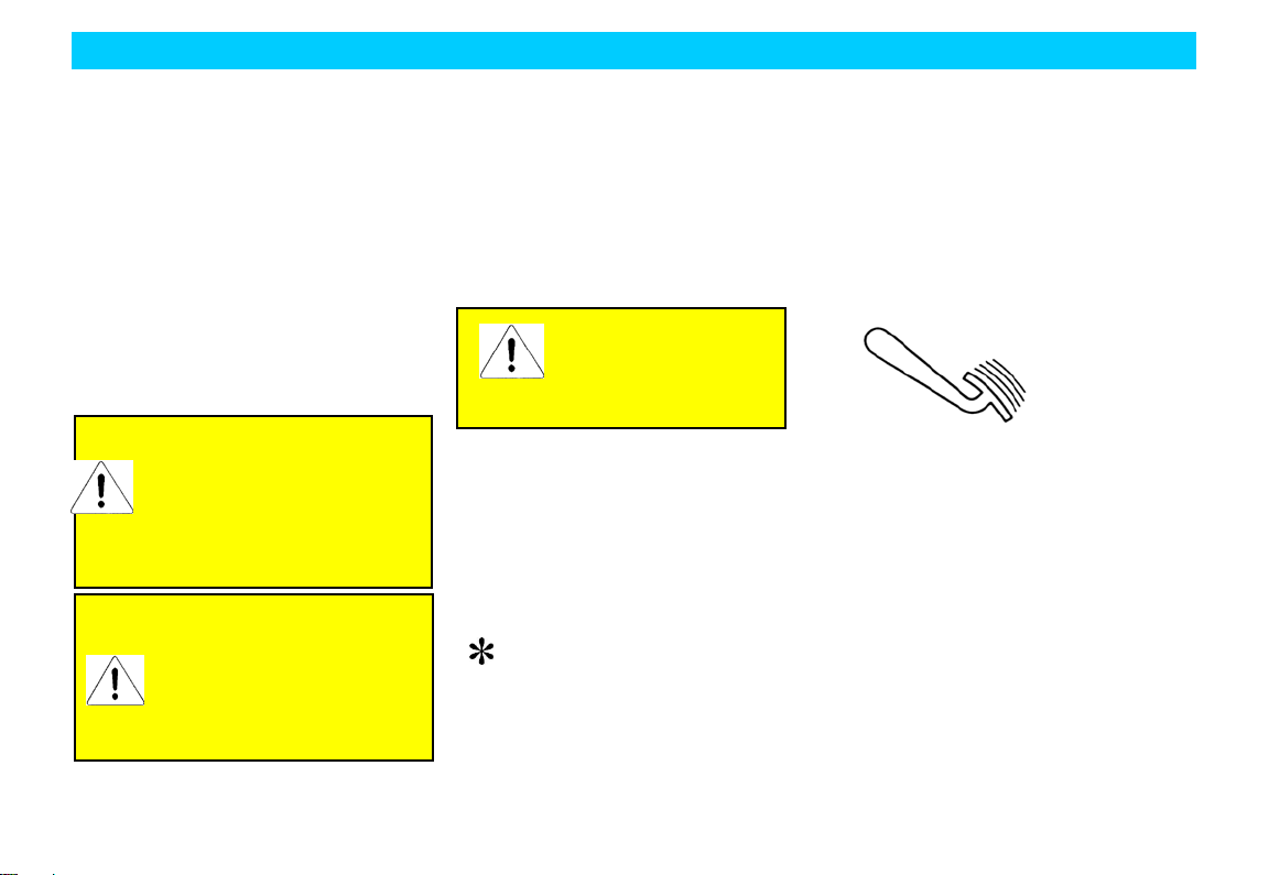
When this symbol is present on
the vehicle, make sure to read
t he relat ed ch ap t er s of t his manual before
any operation.
working of environmental protection.
It’s the important step to achieve such
objective by operating your vehicle
properly and disp osing t he used clean in g
articles and lubricating materials in
accorda n ce w it h t he law s and r e gulat ions .
This manual disp lays the information on
this aspect by means of tree symbol.
We must contribute our
res p ons ibi lity and liabi lit y in t he
2
Page 12

Summary
New Vehicle Inspection
Before deliver in g t he vehicle to y ou, the
dealer of Chery Company has already
performed the vehicle inspection in
accordance with the regulations of Chery
Aut omobile Co., Ltd. T he dealer of Chery
Company should fill in the vehicle
delivery date in the “Vehicle Delivery
Inspection Certificate” column of this
manual and seal with t he st amp of dealin g
agency.
The dealer should verify the entire vehicle
performance and introduce the operation
knowledge of the vehicle against the
“Chery Vehicle Sale & Delivery Card”
dually signed by the salesman and the
user.
Run in o f New Vehi cle
Due to the manufacture and assembling
deviations, the friction resistances between
the moving components of the new vehicle
at the initial stage of operation will be
much greater than the ones in normal
condition. The run in effects of the vehicle
at the init ial stage of op eration will exert
great influence on the use lifetime,
working reliability and economy of the
vehicle, therefore, the use of new vehicle
must abide by the run in regulations
strictly.
Run in Regulation within 1,000 km
Full speed driving is absolutely
prohibited;
Generally, do not drive the vehicle at
the speed above 100 km/h;
Avoid driving at the top speed at any
gear.
Run in Regulation from 1,000 k m to 1,500 km
Increase to t he top speed gr adually or
drive at the allowable max. engine
speed.
Notice during Run in Period
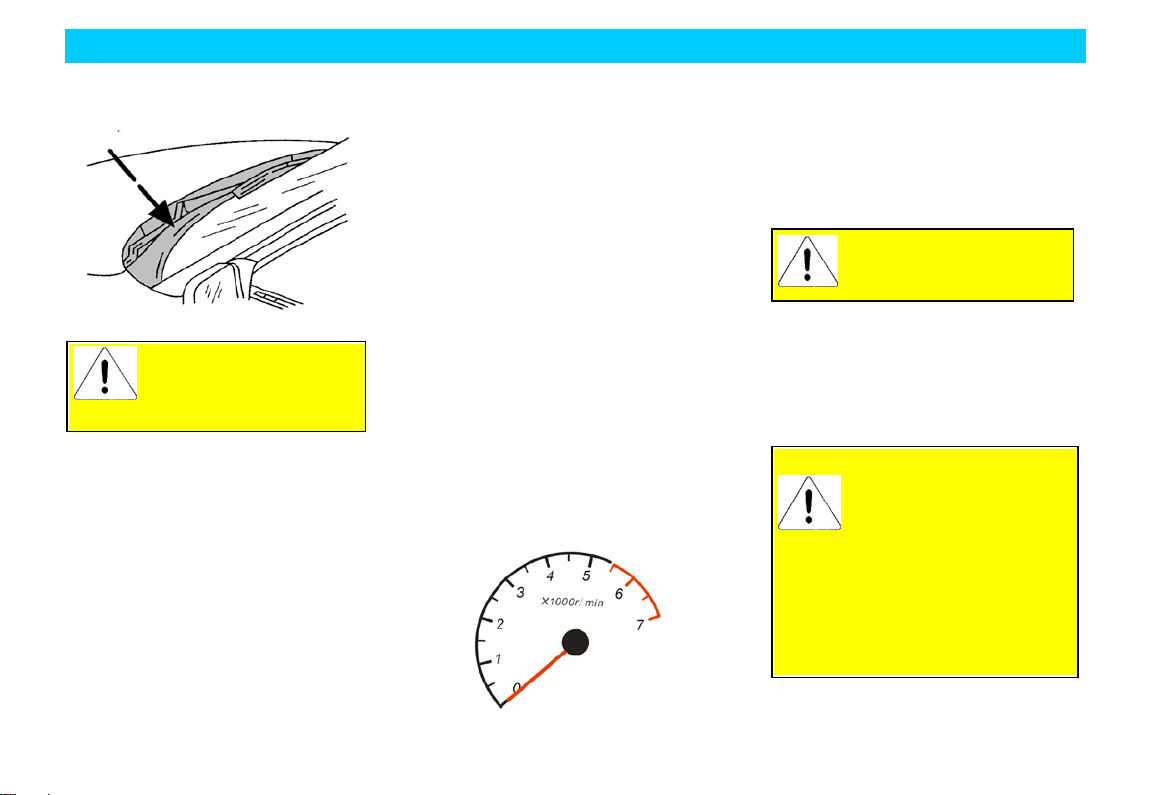
For the driving of vehicles with engine
tachometer, the allowed short period top
engine speed is 6000 r/min. During the
manual ge arshift, make sure to shift to the
next high gear when the engine tachometer
indicator reached red indication area at the
latest.
Avoid the runnin g of en gine at
unnecessary high speed. The
earlier shift to high gear will
help save the fuel, reduce the working
noise as well as diminish the
environmental pollution.
The engin e sp eed should not be exces sive
low during drivin g. Shift t o p rop er gear at
reasonable time.
In cold engine condition, do not run t he
engine at t op speed on neutral gear or any
other driving gear.
The new t ires don’t have best adhesion at
the beginning of use; therefore, the tires
also need run in. The vehicle speed should
be relatively low during first 100 km
driving and the driving should be
extremely careful.
3
Page 13

Summary
The new brake friction linin g a lso needs
run in, since the brake doesn't have ideal
friction force dur in g first 200 km drivin g.
During this period the brake effect is a
little p oor, t herefore t he pressure on brake
p edal may be reasonably increas ed. Such
condi t ion is als o ap plica ble e ach t im e it ’s
replaced with new friction lining.
When the new vehicle traveled up to
800km, the wheel nuts must be
re-tightened to the specified torque. Please
refer to the chapter “Specification and
Parameters” of this manual for correct
torque values. Also, if the wheel has been
replaced or the wheel nuts have been
loosened, then the wheel nuts should be
re-tightened in accordance with the
specified torque after 800km.
“One-To-One” Se rvi ce
In order to provide you wit h better service
and vehicle use, the dealer of Chery
Company will appoint one service counsel
to serve you at the purchase of your
vehicle. In case of any problems during
your vehicle use, you may contact your
service counsel, who will provide you
with best service.
4
Page 14
Summary
Vehicle Owner Name (Unit) Responsible Service Station Name
Ve hicle Delivery Inspection Ce rtifica te
This is to certify that this vehicle has completed the vehicle
delivery insp ection defined by Chery Automobile Co., Ltd. and its
quality meets with the technical specification of Chery Automobile
Co., Ltd.
Vehicle Delivery Date:
Dealer Stamp:
—————————————————— —————————————————————
—————————————————— —————————————————————
Address ————————————— Responsible ————————————
——————————————————————
5
Page 15
Model
Body VIN No.:
Transmi ssion No.:
Delivery Date
Summary
Dealer Stamp
Engine S e rial No.:
6
Page 16

Chery Vehicle Sale & Delivery Sheet
Entire
1
Engine
Yes □
No □
2
Engine oil, brake liquid, st eering liquid, cool ant, batt ery liquid, windscreen
Yes □
No □
3
VIN number, engine serial number, nameplate and other identifications
Yes □
No □
4
Entire vehicle locks and keys
Yes □
No □
5 Entire vehic le lamps, including head lamp, t urn lamp, fog lamp, combined
Yes □
No □
6
Windscreen glass and body paint
Yes □
No □
7
Speedometer, engine tachometer, odometer
Yes □
No □
8
Hub cap, spare tire, vehicle attached tools and entire vehicle operation
Yes □
No □
9
Safety belt, s eat, cigar ett e lighter, A/C swit ch and vent, glove box and sun
Yes □
No □
10
Glass lifter, rear view mirror, wiper, washer, horn, radio (CD player) and
Yes □
No □
Summary
Category No. Item Whether it’s inspected OK
Vehicle
Performance
cleaning liquid.
lamp, compartment lamp, brake lamp, backup lamp, tail lamp, reading
lamp, and instrument lamp.
manual
visor.
antenna
and clearly explained
7
Page 17

Summary
Operation
Knowledge
Salesman Signature: Date: User Signature: Date:
1 93# gasoline fuel Yes □ No □
2 Normal operation during run in. Yes □ No □
3 Operation of entire vehicle lamps Yes □ No □
4 Meaning of alarm indicators Yes □ No □
5 Correct maintenance period and mileage Yes □ No □
6 Vehicle maintenance items in winter and summer. Ye s □ No □
7 Correct understanding of cooling system/coolant usage. Yes □ No □
8 Correct operation of A/C Yes □ No □
9 Notices for vehicle start Ye s □ No □
10 Correct operation of audio equipment Yes □ No □
8
Page 18

Summary
Form one-Saved by service stations
“One-To-One” Counseling Servi ce Card
(Service Station)
User Name: Vehicle Purchase Date
Sales Agency: Model:
Vehicle VIN Number:
The follow in g i tems s hould be con fi r m ed by th e use r.
I. Relat ed it ems confirmat ion at vehicle delivery (“√" for Yes as
“×” for No)
□ Basic vehicle op eration method has been introduced and the
onsite delivery inspection is certified OK.
□ Quality warranty policy has been introduced.
□ Vehicle driving notice has been introduced.
□ The importance of vehicle periodical maintenance and
maintenance period/mileage has been introduced.
□ The importance of vehicle maintenance/repair at Chery
authorized service station has been noted.
□ User’s Manual has been handed over and the reading is
reminded.
□ The function and operation method of service hotline of Chery
Company has been noted.
II. “One-To-One” counselin g servi ce mod e introduction (“√” for
Yes as “×” for No)
□ Cont act the s ervice couns el inst ead of any one else in case of
any problems or needs.
□ The service counsel appointed by the service station is the
exclusive person to communicate and contact with the user.
□ One user is only served by one service counsel: “One-To-One”
□ User may choose other service counsel when he dissat isfies
with current service counsel.
III. M ajor job int roduction of service counsel (“√” for Yes as “×”
for No).
□ Repair maintenance service reception
□ Complaint acceptance
□ Periodical maintenance reminding visits
□ Repair/Maintenance counsel explanation
□ Periodical greeting visits
□ Repair/maintenance reserv ation acceptance
□ Service activity reminding visits
□ Annual authentication reminding/acceptance
□ Important festival greetings
□ Other activities of user’s needs
IV. Establishment of “One-To-One” counseling service
relationship.
Service Counsel Card
User Signature/Date: Service Counsel Signature/Date:
9
Page 19

Summary
“One-To-One” Counseling Service Card
(Customer)
User Name: Vehicle Purchase Date
Sales Agency: Model:
Vehicle VIN Number:
The follow in g i tems s hould be con fi r m ed by th e use r:
I. Relat ed items confirmation at vehicle delivery (“√" for Yes as
“×” for No)
□ Basic vehi cle oper ation method has been introduced and the
onsite delivery inspection is certified OK.
□ Quality warranty policy has been introduced.
□ Vehicle driving notice has been introduced.
□ The importance of vehicle periodical maintenance and
maintenance period/mileage has been introduced.
□ The importance of vehicle maintenance/repair at Chery
authorized service station has been noted.
□ User’s Manual has been handed over and the reading is
reminded.
□ The function and operation method of service hotline of Chery
Company has been noted.
II. “One-To-One” counselin g servi ce mod e introduction (“√” for
Yes as “×” for No)
□ Cont act the s ervice couns el inst ead of any one else in case of
any problems or needs.
□ The service counsel appointed by the service station is the
exclusive person to communicate and contact with the user.
□ One user is only served by one service counsel: “One-To-One”
□ User may choose other service counsel when dissatisfied with
current service counsel.
III. M ajor job int roduction of service counsel (“√” for Yes as “×”
for No).
□ Repair maintenance service reception
□ Complaint acceptance
□ Periodical maintenance reminding visits
□ Repair/Maintenance counsel explanation
□ Periodical greeting visits
□ Repair/maintenance reserv ation acceptance
□ Service activity reminding visits
□ Annual authentication reminding/acceptance
□ Important festival greeting
□ Other activities of user’s needs
IV. Establishment of “One-To-One” counseling service
relationship.
Ser vic e Counsel Card
User Signature/Date: Service Counsel Signature/Date:
Form two-Saved by customer
10
Page 20

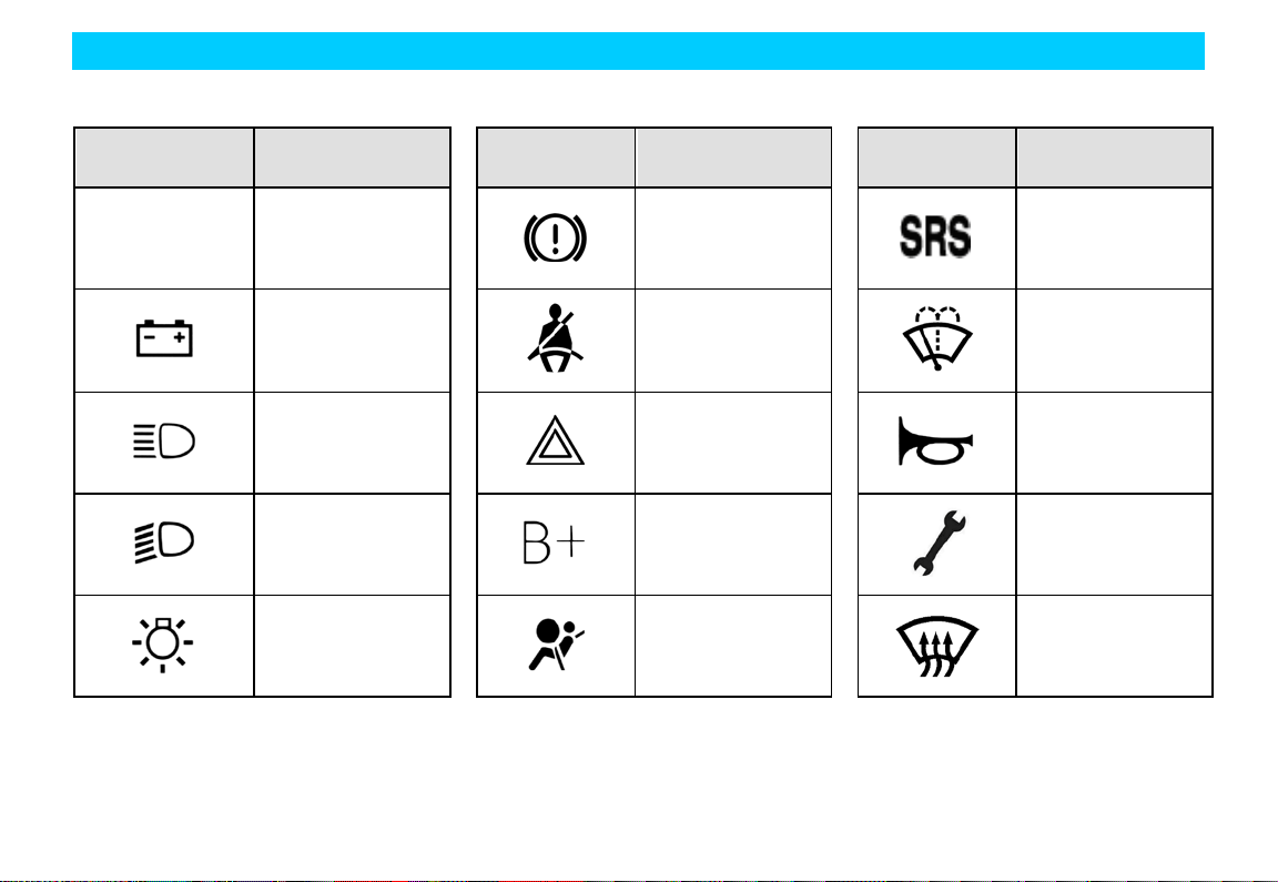
C ommon Vehi cle Sy mb ol Instruction
Window regulator
Window regulator
Engine oil pressure
Rear fog indicator
Engine trouble
Coolant temperature
indicator (red
Front fog indicator
Summary
Symbol Definition
Engine
self-examination
trouble light
switch forbidden
li ght
li ght
Symbol Definition Symbol Definition
ABS Anti-lock brake
system
switch
war ning lamp
Cigarette lighter
Position lamp
alarm lamp
indicator)
Audible alarm
11
Page 21
Summary
Battery charge
Air bag trouble
Symbol Definition Symbol Definition Symbol Definition
A/C A/C system switch
indicator lamp
High beam lamp
Low beam lamp
Head lamp switch
Brake system trouble
alarm lamp
Fasten the safety belt
Hazard flash warning
lamp
Power + pole
indicator
Air bag identification
Windscreen cleaning
Horn
Vehicle maintenance
indicator
Windscreen
defrosting
12
Page 22
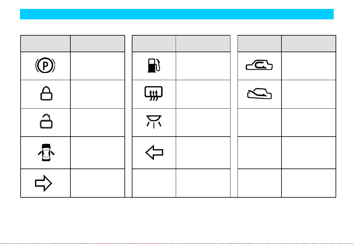
Summary
Parking brake
Rear windshield
Warning light for
Symbol Definition Symbol Definition Symbol Definition
indicator
Lockup indicator
Unlock indicator
door open
Right turn indicator
Low fuel l eve l al arm
indicator
heating indicator
Interior lamp switch
indicator
Left turn indicator
Internal air
circulation
External air
circulation
13
Page 23

Driving
Chapter 2 Driving
14
Page 24
Driving
The long period high speed
the engine and the exhaust system,
Do not start the vehicle in the
locations since the vehicle
Start
Preparation before Start
The engine start is controlled by the
engine electrical control system.
Do not step on the accelerator before start
and during start when starting the
elect ric al inj ect ion en gine. T he acce ler at or
should be used only when having difficult
in starting. Please refer to the “Engine
Start” for the details of vehicle start.
idling running of the engine
will result in the overheating of
which may result in the danger of fire or
other damages. Therefore, do not p a rk
on the ground covered with dry grass
and other dry coverings.
closed gara ge or other closed
exh aust gas is poisonous . M ake s ure t o
op en t he gara ge gate bef ore t he en gin e
start. Refer to the section “Caut ion of
Vehicle Exhaust Fume” for details.
Safety Notice
The idle speed of the en gin e is controlled
by the electrical cont rol syst em. The idle
sp eed at engine st art is quit e high to help
increas e the en gine t emper ature. The idle
speed should reduce automatically when
the engine temperature is increased. Please
deliver your vehicle to the Chery
authorized service station for overhauling
if the idle speed can’t reduce automatically.
Do not run the engine at the sp eed high er
than specified idle speed for more than
10min.
Before Vehicle Start
1. M ake sur e all p as s enger s ar e fas t ened
with safety belt. Please refer to the
chapter “Seat and Safety Protection”
for the details of safety belt and its
correct operation method.
2. Make sure the front head lamp and
other electrical fittings are turned off.
3. Make sure to lift up the handbrake.
4. M ake sur e t hat t he gear se lect or lev er
is at neutral gear.
5. Switch the ignition switch to “Ⅱ”, but
not to (Ⅲ).
If the rotation of the key needs great effort,
it may rot at e the steering around, till the
key can rotate freely. The occurrence of
such condition may have following
causes:
• Deflection of front wheel.
• T he front wheel touched with the road
curb.
• The steering wheel is rotated during
get -on and get-off (self-lock of the
steering wheel).
15
Page 25

Driving
If you smell the fume
authorized service station for
overhauling immediately. Do not
6. At the same time when the ignition
key is t urned on, make sure that the
dashboard alarm lamp lights shortly. If
not, then it needs to deliver your
vehicle to the Chery authorized service
station for overhauling.
If the driver safet y belt is fastened before
turning on the ignition key, then the safety
belt alarm lamp won’t light.
Engine Start
1. Rot ate t he ignit ion switch t o the “Ⅲ”
position but not step down the
accelerator, release the key after the
engine st art and t he key will return to
the“Ⅱ” position.
2. If t he temp erature is normal or higher,
then the engine can not be started
within 5s during the start, and then
rotat e the key to t he “B” p osit ion and
wait for 10s before retrying.
3. If t he temp erature is lower, the engine
can not be started within 15s during
start, and then rotate the key to t he “B”
position and wait for 10s before
retry ing. If the two consecutive starts
all fai l, then st ep down the accelerat or
p rop erly and then rotat e the key to the
“Ⅲ” position. After the engine start,
release the key and release the
acce lerat or p edal s low ly as t he engin e
speed increases.
4. After the engine start, run at idle speed
for several seconds, step down the
clutch, shift to the drive gear, release
the handbrake and then be ready to
drive.
5. The normal environment temperature
condition of the engine start is
-25℃-+40℃ (it m ay ha ve othe r
abnormal conditions when the
environment t emperate is out of such
scope).
Caution of Vehicle Exhaust Fume
Although the vehicle exhaust fume is little
poisonous, it contains the carbon
monoxide, of which the danger must be
cautioned. The certain contents in the
engine exhaust gas and the certain
chemi cals cont aine d or em it t ed by cer t ain
vehicle components may result in the
cancer, the defect of the newborn.
peculiar smell within the
vehicl e, please deliver your
vehicle to the Chery
continue to drive. The exhaust fume is
poisonous that may endanger the life.
The exhaust system and the vehicle
ventilation system should be checked
under the following conditions:
• When the vehicle is lifted for
overhauling.
• When the sound of exhaust system is
changed.
• When the veh icle is d amage d due to
the collision.
Ventilation Notice
When the vehicle is parked in the open
field for long period idle, the window
should be opened for at least 2.5cm. Or
open the A/C system ventilation function
to let the fresh air into the vehicle.
16
Page 26
Driving
Clean t he snow, leaf fall or
other foreign articles
Please do not st ep down the
Turn off the ignition switch, the
engine and the radiator
again du e to excessive high
Therefore, cautions
engine.
blocked in vent so as to
make sure good ventilation.
Engine Control System Self-a da pt i ve Function
If the batt ery cable is on ce removed from
the battery, after connection again, the
vehicle may present some abnormal
phenomenon during the initial period of
the driving. This is t hat the engine cont rol
system is re-learning to adapt to the engine,
which is normal.
Engine RPM Limit
The highest speed limit
In order to avoid the engine overspeed,
when the rpm exceeds the highest
regu lated sp eed, the ECU w ill cut off t he
injection pulse, and the injector stops
injection. It works again when the rpm
decreases within the range of the normal
speed.
Fuel supply is cut off at the time of sudden
deceleration
To reduce the fuel consumption and
exh aust p ollution, when t he throt tle valve
closes suddenly, if the engine rpm is
higher than the set idle speed, the ECU
will cut off the injection p ulse. When t he
rp m de creas es w it hin t he set idl e sp eed, it
resumes the fuel injection.
Engine stall
Release the accelerator pedal. Wait the
engine to lower to idle speed and then turn
off the ignition switch.
accelerator pedal before
turning off the engine.
After long p eriod high sp eed drivin g, do
not turn off the engine immediately during
parking. Run the engine at the speed
higher than idle speed for two more
minutes so as to lower the engine
temperature gradually.
temperature will still be very
high after the t urn-off of the
electrical cooling fan will still keep
running about 10min. Even the cooling
fan stops running, it may run suddenly
temperature.
should be taken when working near the
17
Page 27
Driving
In case of the failure of one
In case of the
occurrence of such condition, please
deliver your vehicle to the Chery
authorized service station for
Please refill with brake
liquid immediately to
deliver your vehicle to the Chery
authorized service station for the
Brake
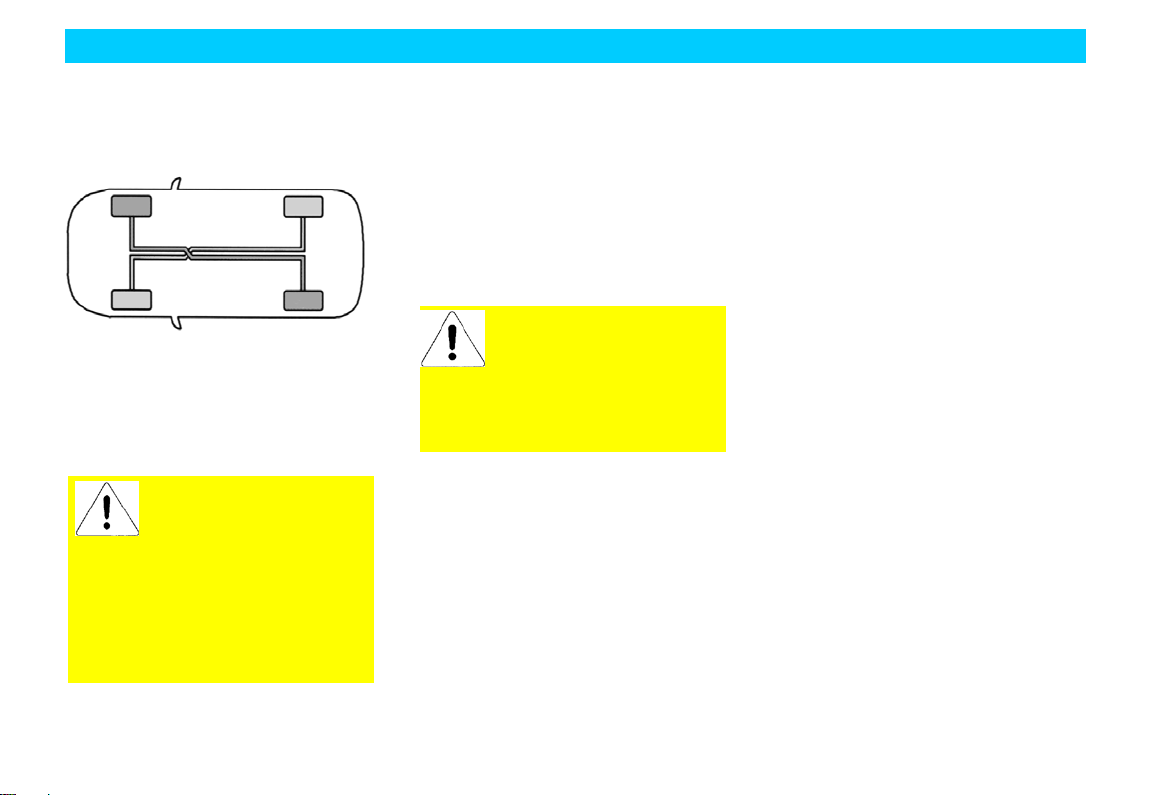
Dual-Circuit Brake System
Your vehicle is equipped with “X”
dual-circuit brake system. The other
circuit will still keep effective operation
even if one circuit has fault.
brake circuit, it will needs
more force to s tep down the
brake pedal and the st op dist ance will
be lengthened.
overhauling before you continue your
journey.
Brake Liquid level alarm
If the brake fluid level warning lamp is on,
which shows the brake fluid level has been
lower than the lowest level, and it needs to
be refilled immediately.
The brake liquid level should be checked
periodically in accordance with the
requirements.
between M AX and MIN marking and
checking of the brake system.
maintain the liquid level
Ope ration Instruction of Brake System
It’s quite normal if the brake system issues
noise occasionally. The long period
grinding or screaming noise bet ween the
met al and t he met al may indi cat e t hat t he
brake disc was severely worn out and
should be replaced. At that time, please
deliver your vehicle to the Chery
authorized service station for overhauling.
If there is consecutive shake or shock
transmitted to the steering wheel during
braking, please deliver your vehicle to
Chery authorized service station for
overhaulin g immediately.
The new brake lining can achieve best
brake eff ects only after run in. The brak e
effect s may be slight ly lowered within the
initial 200k m. Under such condition, the
brake effects can be compensated by
enhancing the prop er force on the pedal.
This essential point also applies to the new
brake lining after replacement.
The worn-out status of the brake lining
depends on the working condition and
driving method to large extent. For the
vehicl es mainly for city transp ort ation, the
working condition of the brake lining is
relatively poor due to the frequent start
and stop. Therefore, make sure to deliver
your vehicle to the Chery authorized
service st ation for the checking of brake
lining thickness or the replacement of
brake lining in accordance with the
maintenance mileage specified in the
Maintenance.
For downward slope driving, it should
shift t o low gear at p roper time so as t o
sufficiently take advantage of the brake
18
Page 28
Driving
All pedals should be
effects of the engine and reduce the load
of brake system. At that moment, the
brake pedal should be stepped down all
the time even the braking is required.
The moisture brake disc will reduce the
brake efficiency. After paddling, heavy
rain or car wash, it should step down the
brake pedal slightly to generate friction
heat between the brake disc and t he brake
lining so as to evaporate the water and
resume brake effects.
If the vehicle is equipped with front
overheats due to poor heat dissipat ion to
reduce the brake effects.
sp oiler, it should ensure the free
airflow to the front brake;
ot her wis e t he br ake s y st em may
The brake booster is subject to the control
of engine v acuum. This device
will act only when the engine
is running. Therefore, do not
turn off the engine for sliding when
driving on downward slopes.
Brake Booster:
If the brake booster can’t function because
the vehicle is trailed or it ’s due t o its ow n
fault, then it needs to enhance the stepping
force to compensate the boosting effects of
the booster.
stepped down to the end
Therefore, it’s preferable not to place the
foot cushion or other covering on the floor
around the pedal. If really needed, then
make sure that the placement of foot
cushion won’t obstruct the pedal
movement without any sliding.
and should fully return
with free movement.
Anti-lock Brake Sys tem (ABS)
)
(
The ant i-lock brake system can avoid the
lock of the wheels that can keep the
st eering performance of t he v ehicle ev en
under emergent braking so as to escape the
obstacles.
The ABS on this vehicle inte grat es EBD
system (Electric Brake force Distribution),
making the ABS performance better.
Reaction of ABS
The ant i-lock brake sy st em will func tion
only during brak in g. During braking, the
pulse movement of the brake pedal
together with the noise indicates t hat the
ABS is under working. Such pulse
movement and noise are normal. At such
moment, do not release the pedal.
19
Page 29
Driving
Though ABS can ensure t he
best brake effects,, the stop
conditions. The ABS can’t always
make sure to reduce the braking
distance, such as on sand or snow
than the one of the vehicle without
foregoing vehicle, paddlin g, e xc essive
turns.
The lighting of ABS alarm
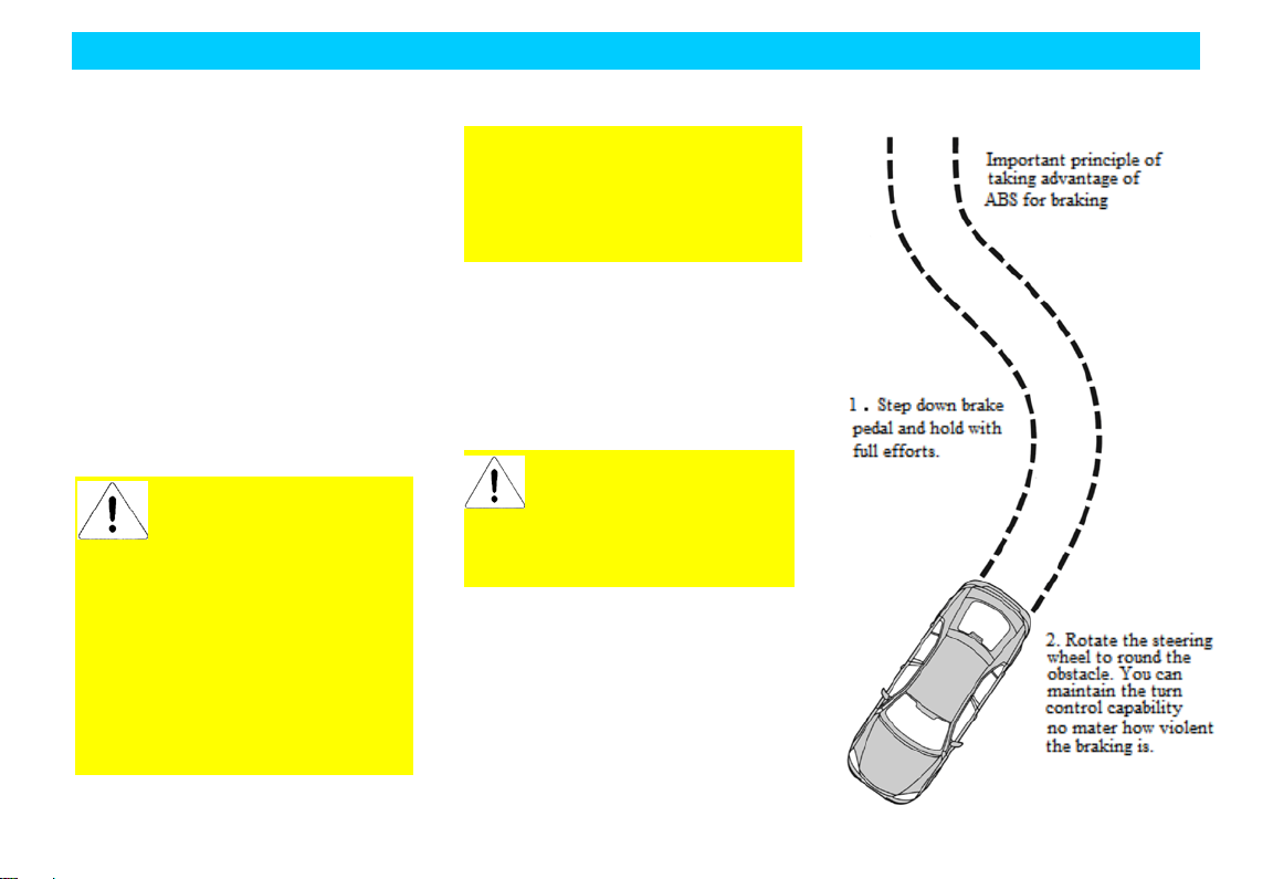
Braking by taking Advantage of ABS
The consecutive stepping down the brake
pedal with full force under emergent
condition will actuate the antilock brake
syst em immediat ely t o keep the control of
steering. If with enough space, you still
can escape the obstacles.
It’s recommended that you should get
famil iar with this brake technology first ly ;
however, any unnecessary adventures
should be avoided.
distance will have great
difference depending on the road
ground, the braking distance of the
vehicle with ABS may be much longer
ABS. Also, taking advanta ge of AB S
can’t eliminate the dangers arising
from the excess ive short dist ance wit h
fast t urn or poor road as well as avoid
t he accid ents aris in g from t he car eles s
and incorrect driving. Please drive
careful ly and decelerat e the dr iving at
ABS Self-Examination
The ABS will conduct the
self-examination after the vehicle start.
The mechanical noise can be heard durin g
this period, which is quite normal.
lamp during driving indicates
the fault in the AB S system.
Please park the vehicle and cont act
with Chery authoriz ed service st ation
timely to repair the ABS system.
20
Page 30
Driving
Handbrake
Pull up the handbrake handle after parking
so as to avoid the humping due to
temporary carelessness. The hand brake
handle is located at the middle of the front
row of seats.
handbrake handle before leaving the
vehicle.
The brake lamp will light when applied
with handbrake under the condition that
the ignition switch is turned on.
Pull up the handbrake lever when using
handbrake.
Make sure to pull up the
When releasin g the handbrake, p ull up the
handbrake lever slightly, push down the
release butt on at the end of the handle and
push downward.
The handbrake is applied on the rear
wheels. It can step down the brake pedal at
the same time t he handbrake is p ulled up
so t hat it can pull up t he handbrake much
easier.
Shift
Use/Operation Method and Notices:
• During gearshift, fully s tep dow n t he
clutch pedal and release the driver
from the engine torque and then
operate the gearshift lever for gearshift
rapidly.
• The low speed gear should be used for
downward slop es and turns . The slide
with disengaged clutch is not allowed.
• When shifting the transmission from
low gear to high gear, do not conduct
gear skip operation; otherwise the
service life of t he sy nchronizer will be
affected.
• The forced gearshift by means of
sy nchronizer to start the engine under
neutral gear and engine stall status is
strictly prohibited; otherwise the
service life of the synchronizer will be
affected.
• The flap method (namely the operation
method of one pulling and one
releasing) is strictly prohibited during
gearshift. Please always hold the
transmission lever with hand so as to
greatly reduce the slide and friction
time and the worn-out of the
synchronizer lock ring.
• Do not leave your hand on the gear
selector lever during driving;
otherwise it will result in the early
worn-out of the gearshift fork.
• In case of the detection of any
abnor mal evidenc es s uch as abnormal
noise of the transmission or the
obvious heavier operation during use,
p lease st op the vehicle for insp ection
immediately and continue the driving
once the trouble is resolved.
Steering
21
Page 31

Driving
Make sure to use unleaded
result in the permanent
Co., Ltd. will not be liable for any
with the nearest Chery authorized
service station.
In order to avoid the damage of power
steering system:
• The time when rotating the steering
wheel to the end (to left dead point
and right dead point) should not
exceed 10s during engine running.
• When the p ower st eering liqu id in the
power steering liquid reservoir is
lower than “MIN” mark, please refill
with power steering liquid
immed iately. Do not drive the vehicle
before refill.
In case of trouble of power steering
syst em or the engine stall, the vehicle will
lose the steering boosting. You still can
rotate the steering wheel with great
strength.
In case of vehicle deflection or tremble
during the driving, please check the
following items:
• Whether the tire pressure is
insufficient.
• Whether the tire is worn evenly.
• Whether the suspension components
are loosened or worn out.
• Whet her t he st eering comp onent s are
loosened or worn out.
• Whether the wheel alignment is
correct.
Paddling
If it’s must to paddle during journey, make
sure to drive slowly and carefully,
especially when having no knowledge of
the water conditions. Do not drive forward
further if the water can submerge the
wheel hub.
During paddling, the traction force and the
brake performance of the vehicle will b e
lowered and the vehicle will have the
danger of stall.
In case of the water ingress int o t he intake
pipe of the engine, it will cause the serious
damage of the engine. The deeper
paddling will result in the water ingress
into the transmission through the
t rans mis sion air ve nt , w hich will r es ult in
the damage of the transmission.
Aft er paddling, make sure t o drive slowly
and step down the brake pedal slight ly for
several times to remove the water from the
brake. The water on the brake will lower
the brake performance.
Three-W ay Cat al y t i c Converter
The catalytic converter will help reduce
the pollution of exhaust gas.
fuel. The leaded fuel will
dama ge of t he cataly t ic convert er and
the oxygen sensor. Chery Aut omobile
damages arising from the use of leaded
fuel. Su ch damages are excluded from
the warranty scop e. If y ou refill with
leaded f ue l acc identally, p leas e contact
22
Page 32

During the running of the
gasoline engine, it’s
absolutely not allowable to
pull out the sp ark wire of the ignition
Check if the engine functions
normally by means of cylinder stall
method or observe the jump spark
In case of the evidence of
lowered performance
during driving, please drive at low
The vehicles with gasoline engine are
equipp ed with narrow refill op ening that
only accom modat es t he unl ead ed gasol in e
p ump refuelling gun nozzle.
coil.
condition of t he sp ark p lug; otherwise
the three-way catalytic converter will
be damaged.
Driving
Please avo id the cond ition that will result
The three-way catalytic converter
will be getting very hot if the engine is
under continuous running, therefore,
notice to wear the p rotective glove dur in g
repair so as to avoid the scalding.
Drive the Vehicle Equipped wit h a Catalytic Co nverte r
poor engine ignition or the
sp eed to the nearest Chery authoriz ed
service station. Do not drive at large
accelerator.
in the ingress of the un-combusted or
partial un-combusted fuels into the
catalytic converter, especially when the
engine is at high temperature.
The following conditions should be avoided:
• Run out of fuel.
• Unnecessary long period start of the
engine.
• Run the engine under the condition
that one spark plug cable terminal is
removed.
• Start the vehicle with the engine still at
working temperature by means of
pulling or hauling.
• Turn off the ignition switch during
driving.
Parking
Do not park, idle or drive the vehicle on
the dry leaves or grass. Even the engine is
turned off, the exhaust wit hin short period
will continue the radiation of equivalent
heat, and therefore, it still has potential
fire danger.
23
Page 33

Driving
M ake sure to turn off the ignition switch
before le aving the vehicle. Do not run t he
engine when no one is in the vehicle. The
negligen ce of t his p oint may result in the
movement of the vehicle, which will result
in the body injury or property damage.
Chassis Protection
Your vehicle is equipped with heat
insulation plate. Do not app ly the paint on
the body of heat insulation plate, exhaust
pipe or catalytic converter or the
surrounding areas. D o not disassemble t he
heat insulation plate.
Fuel Consumption
The fuel consumption is influenced by the following factors:
Selection of Vehicle Speed or Gear
The above figur e illust rates how
the fuel consumption is
influenced by the selection of
vehicle speed and gear. Maintaining at low
gear to improve the acceleration
performance will result in the obvious
higher fuel consumption.
Stroke Distance/Engine Temperature
The frequent cold vehicle start and the
short distance journeys will result in the
obvious increasing of the fuel
consumption.
Traffic and Road Condition
The crowded traffic, upw ard slop es, multi
curved routines and rough roads will cause
detrimental influence on the fuel
consumption.
Good Driving Habits
The prediction of danger and keepin g safe
driving distance with foregoing vehicle
will not only reduce the fuel consump t ion
but also reduce the wearing and noise of
the brake.
It’s recommended to turn
off the engine during traffic j am or
long period waiting such as red
li ght , becaus e t he engin e id ling for
long time will increase the fuel
consumption.
24
Page 34

Driving
After stopping the vehicle
under hot condition and will stop
fan may still start suddenly in case of
temperature (sunshine exposure or
cautions should be taken when
Vehicle Load Status
The increasin g of vehicle load will result
in the higher fuel consumption.
Vehicle Technical Status
The low tire pressure or improper engine
and vehicle maintenance also will result in
higher fuel consumption.
Essentials for Fuel- Saving Driving and Environmental Protection:
• Fuel-saving driving and use excess
electrical loads only if needed.
• Start without the heating of the
vehicle.
• Use the accelerator smoot hly.
• Shift to the next higher gear as soon as
p oss ible s o as t o achieve lower en gin e
speed.
• Prediction of traffic condition.
• Turn off A/C and rear windscreen
heating immediately whenever
unnecessary.
• Check/adjust the tire pressure
periodically.
• Conduct vehicle maintenance
periodically, preferably conducted by
Chery authorized service station.
Rad i ator F an
The radiator fan is an electrical fan with
the working condition controlled by the
engine ECU. This switch will
automatically turn on t he fan circuit when
the coolant or the engine compartment
reached to certain temperature.
and the engine, the radiator
fan will continue runn ing for
certain period since the engine is still
running when the en gine is cooled to
cert ain temp erat ure. Even thou gh, t he
the sudden temperature increasing of
the engine compartment due to the
influence of the ambient environmental
high temperature region). Therefore,
operating in the engine compartment
so as to avoid the accident.
Instruction
If the fan isn’t running when the coolant
temperature reached the fan start
temperature, then check if the fan fuse is
burnt out. Replace the fuse if necessary.
The fan speed is independent from the
engine sp eed and the gearshift t o low gear
will not promote the cooling effects of the
fan. Therefore, it ’s unnec essary to s hift t o
25
Page 35

Driving
influence of the ambient
when operating in the engine
low gear provided that the engine runs
smoothly and the vehicle speed has no
obvious reduction on upward slopes.
and the engine, the radiator fan sill
continue running for certain period
since the engine is still under hot
condition (about 10min) and will stop
running when the engine is cooled t o
certain temperature. Even though, t he
fan may st ill start suddenly in case of
the sudden temp erature increasing of
the engin e to compart ment due to the
environmental temperature (sunshine
exp osure or high temp erature region).
Therefore, cautions should be taken
compartment so as to avoid the
accident.
After stopping the vehicle
26
Page 36

Operation & Adjustment of Inside Devices
Chapter 3 Intro duction of Vehicle Functions &
Instr uction of Designations
27
Page 37

Operation & Adjustment of Inside Devices
time.
I. Int r oducti on of
Vehicle Functions
Steering wheel lock/ignition switch
Combined steering wheel lock/ignition
switch has the following key positions:
“B”
–Ignition switch turns off and the
steering wheel is blocked.
When the key is pulled out from the
ignition switch, the steering wheel lock
acts and the steering wheel is blocked.
To lock the steering wheel, it shall turn it
after the key is pulled out till a click of
blocking is heard.
“I”–unlock the steering system. The circuit
of electric accessories is connected and
small electric appliance such as inside
lights can be operated. But the ignition
switch and main electric loop are
disconnected.
If the key could not or is difficult turn t o
the p osition from “B”, slightly t urning t he
steering wheel and then the locking system
of steering wheel may loosen.
The ignition switch key shall not be placed
at t he position t oo long t o avoid the power
of battery running out of.
“II”–Connect the ignition circuit. All
electric loops can work. Alarm lamps and
indicator lamps light. It is the normal
position of key during driving and the
position that must be selected for towing
the vehicle.
“III”
–Connect the motor and start the
engine. When the lock hole is at the
position, headlamps and electrical
equipment that consume more power will
be disconnected fully.
The ignition switch is equipped with
anti-repeatable start device inside. Once
the engine runs, the device may prevent
mis-start of engine, so that it avoids
damage from the engine and flywheel.
If the engine does not start, the key must be
turned to “B” before restart, and then
turned to the p osition. After start , release
the key and it will return to “II” position.
Once the en gin e start ed, the
key must be released. DO NOT
remain at “III” position for a long
28
Page 38

Operation & Adjustment of Inside Devices
blade whether frozen on the
efore use in cold
may result the wiper motor
windscreen, otherwise it may
Horn
Press down the button on the
steering wheel to operate the horn. The
horn can still work in case of the ignit ion
switch turn-off.
Windscreen Wiper & Cleaning System
When the black dot p oints “ON”, it means
the rear wiper is at normal operation status.
When the black dot points “OFF”, only the
front wiper works as operating the wiper
switch. The rear wiper does not work.
It must check the wiper
windscreen b
season. It must be unfrozen if so.
Ot herwise, the wip er motor will be
damaged,
Op erat ing t he wip er wit h obst acles
such as snow on the windscreen
damaged as well. Obstacles shall be
removed before operating the wip er.
DO NOT operate the wiper on a dry
scratch the glass and make
permanent damage to the blade.
The wiper is only available with the
ignition switch on. There are four positions
and “OFF” is for out of use.
29
Page 39

Inte r mi tte nt Wi pi ng
Move the control lever one position
upward to ‘INT” from “OFF”.
The wiper will automatically act once
every interval.
Normal Wipi ng
Move the control lever two positions
upward to “LO” from “OFF”.
Operation & Adjustment of Inside Devices
High Speed Wiping
Move the control lever three positions
upward to “HI” from “OFF”.
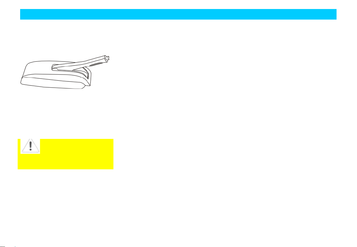
Water Spray Switch
ull the switch handle toward to the
P
steering wheel and hold in the position, the
cleaning fluid will spray out front the
injection noz zle in front of t he windscreen
and the wiper begins action synchronously.
Water spray will stop after releasing the
handle, but the wiper still acts several
times.
Spraying time shall not
exceed 10s once. DO NOT op erate
the sys tem with no cleanin g fluid in
the reservoir. Otherwise it may result
the spray motor damaged.
Inte rior Rearview Mirror
The interior rearview mirror may be turned
to required angle depending on demand.
30
Page 40

Operation & Adjustment of Inside Devices
To reduce the glare during night driving, it
may pul l t he anti-glar e handle ba ckward to
adjust the angle of rearview mirror
properly. The anti-glare handle shall be
returned to original position onward in
daytime.
Exte r i or rea rview mi r ror
Manual adjustment for exterior rearview
mirror:
The driver may press the mirror edge of
rearview mirror to adjust the gradient up ,
down, left or right. Observe the back
condition of the vehicle after the gradient
of left and right rearview mirrors is
suitable for driving.
Adjustment of electric exterior rearview
mirror:
(Electric rearview mirror is optional)
As shown in the figure:
Turn the button from the middle position to
the position of rearview mirror to be
adjusted, move the button with hand to a
proper position of rearview mirror.
Exterior rearview mirrors may be folded
onward or inward manually when the
vehicle is running in a narrow sp ace. T he
mirrors may return to original position
after the vehicle passes the narrow space.
The object in the rearview
mirror looks like smaller and further
than the practical one. DO NOT over
estimate the practical distance of the
object.
31
Page 41

Operation & Adjustment of Inside Devices
Sun Visor
The sun visor may be turned to side
window by unfastening the fasteners.
Articles such as driving license and gate
toll tickets, etc. may be kept in the back of
the sun visor.
The sun visor at the passenger side has
make-up mirror, which is available with
the sun visor turning over.
Control Switches on Front Left Door
The control switches at the driver side
includes regulators for front left and right
electric al windows and front right window
safety switch.
Electrical Window ( )
Front left door
Front right door
32
Page 42

Operation & Adjustment of Inside Devices
Even if the ignition switch turns off, the
electrical windows may work.
The control sw itches on the front left door
may regulate the left and right windows.
When the front right window safety swit ch
on the front left door is pressed, the
regulation of front right window may be
controlled by the control switch on the
front right door.
Press dow n of draw up the sw itch t o open
or close the window. Release the switch
during window glass up or down, the glass
shall remain in the current position.
Every window regulator s witch has pointtouch function, the glass may drop t o t he
bottom automatically when the regulator
swit ch is pressed for 300 milliseconds and
released.
Besides the control switch of driver side
window, the door trim panel in the driver
side is supplied with t he regulator swit ch
for front right window.
Carefully close the window
and observe to avoid injury from
squeezing.
Front Ashtray, Cigarette Lighte r
The front ashtray and cigarett e lighter are
located near to the gear lever.
To op en the front asht ray, you need to pull
its arc backward; to close it, y ou need to
push it to the original position.
Pr ess t he cigaret t e lighter with hand and it
will automatically pop in the original
p osit ion after heat ing, then y ou can pull it
out for use.
Lighting control
Please follow related traffic rules while
using the illumination equipment as below:
The cigarette lighter shall not
remain in inserted stat e for a long time
to avoid danger. It shall be taken away
if a child stays in the vehicle alone.
33
Page 43

Operation & Adjustment of Inside Devices
Headlamp switch
Position light:
Turn the headlamp switch on the
instrument p anel to position, the
small light position, the front and rear
p os ition lamp s and lic ens e plate la mp w ill
light at the same time.
Backlight adjustment:
After the small light turning on, lighting
for instrument panel, sound system, A/C
and switches, etc. will be on. T hrou gh t he
backlight adjusting switch, the brightness
of interior backlight may be regulated.
Dipped headlight:
Turn the headlamp switch on the
instrument panel to
dipped headlight position, the dipped
headlight will be on.
position, the
Con ve rs i on of high be am/ di p ped he adlight
Pull the handle downward and get across
the force bearin g p oint when the headlamp
switch is at t he dipp ed headli ght p os it ion,
namely the dipped headlight is on, it may
convert to high beam. Turn on the high
beam, t he high bea m indicator lamp on the
instrument panel
with. Pull the handle toward to the
direction of steering wheel and return to
original p osition, it may resume as dip p ed
headlight.
will light along
Flicker of Headlamp
If y ou need to flicker the headlamp during
driving, the handle shall be p ulled toward
to t he steering wheel direction at t he force
bearing point and then release the handle, it
will automatically return. Repeat the action
and the headlamp will flicker continuously.
Switches of Front & Rear Fogs
34
Page 44

Operation & Adjustment of Inside Devices
Switches of front and rear fog lamp s are
located at the control handle under the
steering wheel to the left.
When the headlamp switch is at
or position, turn the handle
(the part with black dot as shown in the
figure) will connect the front fog lamp first
and then the rear fog lamp.
To turn on the fog lamp, the headlamp
switch must be turned on first (at
or position), then the front
fog lamp can be switched on. The rear fog
lamp shall not turn on until the front one is
on).
When the front fog lamp is connected, the
indicator lamp on the instrument panel
will light.
The front fog lamp can only be used in
case of visibil ity is serious ly limited s uch
as fog, snow or rain, etc.
When the rear fog lamp is on, the indicator
lamp on the instrument panel
light.
The rear fog lamp has st ronger glare, s o it
will
is only allowed to use in very low
visibility.
Turning Indicator
The turning indicator is available only after
the ignition switch turns on.
Left turning indicator-pull the handle
downward
Right turning indicator-pull the handle
upward
When the turning indicator is on, the
turning indicator lamp on the instrument
panel will flicker.
Inte rior Front and Middle Ceili ng L a m ps
Switch at right: Ceiling lamp off.
Switch at left: Ceiling lamp on.
Switch at middle position: Ceilin g lamp on
with door opening, off with door close.
Danger Alarm Lamp Switch
35
Page 45

Operation & Adjustment of Inside Devices
The triangle shown in the figure is the
danger alarm lamp sw itch, which is in t he
central instrument panel between two air
outlets.
The sw itch is only us ed in emer gency case
for warning the following vehicles t hat the
car has faults or danger. Press the switch to
connect/ disconnect the system. The danger
alarm l amp is availabl e even if t he ign it ion
switch turns off.
After the alarm lamp is connected, the
indicator l amp on t he swit ch (yellow p art)
will flash. Left and right t urning indicators
on the combination inst rument will flicker
at the same time.
Braking Lamp
When step on the brake p anel, t he braking
lamp will be on. It will be off with the
brake pedal released.
Reversing Lamp
When turn on the ignition switch and the
vehicl e is at reverse position, the reversing
lamp will be on. The revers ing lamp will
be off when the ignition switch is turned
off or changed to other position.
36
Page 46

Sound System
Note: Please read the sound system instruction manual supplied with the vehicle if it is not equipped with the system as below.
POWER supply
Preset key 2
CD Panel ( )
①
② OUT key
③ Volume control
Operation & Adjustment of Inside Devices
④ Manual TUNE
⑤ Mute & Clock key
⑥ Preset key 1
⑦
⑧ Preset key 3
⑨ Preset key 4
⑩ Preset key 5
⑾ Preset key 6
⑿ MODE key
⒀ BAND key
⒁ Auto-scan memory key
⒂ Auto-scan key
37
Page 47

Operation & Adjustment of Inside Devices
F u nct ion I nstr uc t ion
① Power key: Press the key to switch
on/ off the power supply.
② OUT key: Press the key for CD out.
③ Volume control: Press the key to
select BASS, TREBLE, BAL,
FADER and VOL in order.
Clockwise turn the potentiometer
for increasing the right output of
VOL, BASS, TREBLE and BAL,
and front output of FADER,
counterclockwise turning is
opposite.
④ Manual TUNE: Under the radio
mode, press the key for upward/
downward t une, long t ime press t he
key for s ingle st ep tune. Under CD
mode, press “∧” or “∨” to select
songs forward or backward, “∧”
for next song (e.g. 1-2) and “∨” for
last song (e.g. 2-1). Press “∨”or
“∧” for fast onward or backward.
⑤ Mute and clock key:
− Under radio mode, press lower left key
for mute switch and LCD shows
“MUTE”;
− Under CD mode, it is pause switch,
press lower right key, convert the
display between radio and clock;
− Under clock st ate, long time press t he
key and the hour disp lay flickers, then
press the key again, the minute display
flickers, turn key ① to adjust clock.
⑥ Preset key 1:
− Under radio mode, it is presetter No.
1;
− Under CD mode, for CD play. Slightly
press the key, and LCD shown
“ SHU F” and it may p lay the songs in
the CD, p ress the key again, it shut s
down t he play function and returns t o
normal play order.
⑦ Preset key 2:
− Under radio mode, it is presetter No.2;
− Under CD mode, repeatedly play the
CD. Press the key for short time, it
will play the current song repeatedly.
LCD shows “RPT”. Press the key
again, it may cancel the repeating
function.
⑧ Preset key 3:
− Under radio mode, it is presetter No.3;
− Under CD mode, it is scan play key.
Press the key and LCD shows
“SCAN” skip to next song, play for
10s and then skip t o next song a gain.
Press t he key to stop scan when you
are hear in g want ed song, and ret urn to
normal play condition.
⑨ Preset key 4:
− Under radio mode, it is presetter No.4;
− Under CD mode, it is the selection key
for EAS (electronic anti-shock). Press
the key for 2s to cancel the ESP
function and LCD won’t show “EAS”.
Press t he key for 2s again to resume
the EAS function and LCD shows
“EAS”.
⑩ Preset key 5:
− Under radio mode, it is presetter No.5;
38
Page 48

Operation & Adjustment of Inside Devices
− Under CD mode, it is programming
memory of CD. Press the key for 2s
when playing CD, save a
programming song and the display
shows [P.XX] (the range for XX is
1-10) that flickers for 5s, press the key
again dur in g fl icker in g t o confirm the
programming song has been saved.
Rep eat t he above p roc ess to s ave next
song, ret urn to normal p lay st ate after
confirmation. When the CD songs of
which are saved is out, t he content for
programming memory will
automatically eliminate.
⑾ Preset key 6:
− Under radio mode, it is presetter No.6;
− Under CD mode, it is CD
programming play. Press the key when
playing CD, the machine will p lay
from the saved song P1 if there are
saved songs. Press the key ④ “∨”,
“∧”, convert to next saved song.
Press the key again to cancel the
p rogrammin g play funct ion and ret urn
to normal play order.
⑿ MODE key: signal selection switch,
which may convert between
radio/CD.
⒀ BAND key: Wave band conversion
switch.
⒁ Auto-scan memory key:
− Press the key 2s, the machine will scan
the whole band from high frequency to
lower and save the channels with
stronger frequency in 1-6 presetters,
and finally stop at the channel saved in
presetter No. 6;
− Under CD mode, it is the
programming elimination of CD. Press
the key 2s to clear p rogrammed songs
and LCD shows [CLR], which f lick er
for 5s. Press the key again in the
flickering period to confirm that the
p rogrammed son gs ha ve b een cleared,
and then return to normal play state. If
no any operation is taken in the period,
it returns to programming play state.
⒂ Auto-scan key:
− Slightly press the key and the radio
searches channels from high frequency
to lower automatically. When a
channel is searched, LCD flickers the
frequency of the channel for 5s, and
then automatically search other
channels.
− When a frequency is flickerin g, long
time press the preset key t o save the
channel in corresponding presetter.
Basic operation of radio
Preparation
− Slightly press the key POWER ①,
turn on the power supply and LCD
shows digits.
− Slightly press AM/FM switch to select
suitable wave len gt h. LCD shows AM
or FM.
Auto-tune
− Slightly press the key “∧”TUNE ④,
the radio search es channels from h igh
frequency to low;
39
Page 49

Operation & Adjustment of Inside Devices
− Pres s t he key “ ∨”TUNE④, the radio
searches channels from high frequency
to low and automatically block the
channel it searched, and show the
frequency of channel on the LCD.
− If the channel is not the one you
wanted, press the key again to search
for next channel.
− Press the key TUNE ④ for 2s for
manual ly s earching channel. Press and
hold the key, the radio will
continuously scan channels, release
the key at once when wanted
frequency is heard. If no any operation
is taken in 3s, it will turn to aut o-scan
state.
− If the channel is caught, press the
above two keys to adjust the frequency
exactly.
S ave or Play Channel
Save channe l
Aft er the channel is obtain ed manually or
automatically, press the preset keys (⑥-⑾)
at least 2s till the radio appears a short
silence and recovers broadcasting. In
addition, LCD shows corresponding preset
key No., which means the channel has
been saved in the preset key.
Play channel
First, select wave band (AM/FM)
according to demand, and then slightly
press the p reset key that saves channel, the
saved chann el will p lay. LCD shows the
corresponding preset key No. and saved
channel frequency. Repeat the above
operation to save or p lay ot her channels
respectively.
Disc maintenance
Please take out the disc while it is not used
and place it in the CD box t o avoid dust
and damage. DO NOT leave your
fingerprint on the disc as taking out. The
disc shall prevent heating and directly
sunshine.
40
Page 50

Operation & Adjustment of Inside Devices
A/C System
Ventilation
Outside air enters in the v ehicle throu gh
the air inlet in the lower part of the
windscr een. P leas e keep t he air inlet clean
without snow and leaves for ensuring
normal heating, ventilation and efficient
work.
41
Page 51

Operation & Adjustment of Inside Devices
42
Page 52

Operation & Adjustment of Inside Devices
1. Side defrost air outlet 2. Side air outlet 3. Defrost air outlet of front windscreen
Central vent hole
The adjusted air flows in the vehicle
through two central vent holes. The air
flow direct ion may be changed by t urning
the grille.
1. Side defrost air outlet 2. Side air outlet 3. Defrost air outlet of front windscreen 4. Central vent hole
Side ai r outlet
The adjusted air flows in the vehicle
through two side air outlets.
Defrost air outlet of front windscreen
Through the air outlet, cold air or warm air
are guided to the side windows (controlled
within exterior rearview mirror).
43
Page 53

Operation & Adjustment of Inside Devices
Ceiling Air Outlet and Control
Passengers who sit in middle and rear
seats may control the airflow dire ction of
A/C by adjusting t he ceiling air outlet and
blower switch.
(Note: the operation is only available in
the case of front blower running.)
44
Page 54

Operation & Adjustment of Inside Devices
Control Panel
1. Cold/warn adjusting switch
2. Airflow distribution switch
3. Blower switch
4. Defrost switch of rear windscreen
5. Internal/external circulation control
lever
6. A/C switch
V enti lation & Warm Air
A/C system adjusts the temperature by
mixing cold and warm air. The
temperature may be constant under any
speed.
The airflow speed is subject to the blower,
which may be started during driving if
necessary.
45
Page 55

Operation & Adjustment of Inside Devices
circulation mode continuously
may result fuggy inside the
Temperature cont rol switch
The switch is used for controlling the
temperature of air flowing out the vent.
Blue position: Cold air
Red position: Warm air
Blower Switch
The switch is used for controlling the
speed of blower (4 steps totally). The
airflow speed is adjusted by the blower.
Starting the blower during driving in order
to increase comfort.
cooling or heating the air inside vehicle.
Using the internal
vehicl e and window mist y, so the
Internal/ external circulation control lever
The lever is used for selecting fresh air
outside or air circulation inside the
vehicle.
External circulation mode (
Outside air enters in the vehicle.
Used for normal ventilation, warm air or
cooling.
Internal circulation mode (
Air inside vehicle circulates within the
vehicle. The mode is used in cases of
dusty environment, or p reventing outside
exhaust gas entering in the vehicle, rapidly
)
)
mode can be used in short time
only.
Airflow Distribution Switch
The switch is used for selecting the
airflow direction.
There are 5 steps for the switch as below:
46
Page 56

Operation & Adjustment of Inside Devices
Head position
Head and foot position
Foot posi tion
Foot posi tion, defrost
Defrost
“Head” position ( )
The air flows out from the central vent
hole and side air outlets.
“Head and foot” position (
The air flows out from central vent hole
and air outlet in the bottom of front seat.
)
“Foot” position ( )
The air mainly flows out from the air
outlets in the bottom of front seats.
“Foot, defrost” position ( )
The air flows out from the air outlets in
the bot tom of front seat, defrost air outlet
of windscreen and defrost air outlet of
front window.
47
Page 57

Operation & Adjustment of Inside Devices
the engine overh eated with it working
jam. Observe the
down the A/C if the engine is
“Defrost” position (
The air flows out from defrost air outlet of
windscreen and defrost air outlet of front
window.
)
A/C System
Ventilation, heating and cooling
components consist of a control system,
which may provide the highest comfort
under any weather condition.
The cooling unit of A /C sy st em cools t he
air down and removes moisture and dust
such as pollen, etc.
A/C switch
The switch is used for starting and
sto pping A/C compressor .
Start the engine and turn the blower switch
to proper airflow speed, switch on the A/C
swit ch for st arting the air conditioner. The
indicator lamp is on with A/C running.
Press the A/C switch button to stop the
A/C. when the blower swit ch is at “O FF”
position, the A/C compressor does not
work.
Max. Cooling
It shall open the windows shortly to
discharge the inside hot air rapidly when
the vehicle expos es in sunshine for a lon g
time in hot weather.
A/C switch: ON
Internal/ ext ernal circulation control lever :
(
Airflow distribution switch: (
Temperature control switch: Turn to the
bottom counterclockwise
(Blue)
Blower switch: Max. rotation speed
)
)
T he A/C sy stem may lead to
while the vehicle is climbing a long
slope or at traffic
water temperature gauge and shut
overheated.
Normal cooling
It is for t he normal cooling durin g longdistance journey and high speed driving.
A/C switch: ON
Internal/ ext ernal circulation control lever :
(
)
48
Page 58

Operation & Adjustment of Inside Devices
Airflow distribution switch: (
)
(
Temperature control switch: Blue
Blower switch: Any posi tion
Head and Foot Position
It is used for transition phase such as the
temperature is low outside, without
sunshine. When adjusting t he temperature
control switch between cold (blue) and
warm (red), the warm airflow enters in the
bott om of t he vehicle, cold air and normal
temperature air flow in upper space.
A/C switch: NO or OFF
Internal/ ext ernal c irculation control level :
(
Airflow distribution switch: (
Temp erat ur e contr ol swit ch: bet ween blue
(cold) and red (warm)
Blower switch: Any posi tion
)
) or
)
Ventilation
Outside air flows in the vehicle through
central vent holes and side air outlets.
A/C switch: OFF
Internal/external circu lation control lever:
(
Airflow distribution switch: (
(
Temperature control switch: Blue
Blower switch: Any posi tion
)
)
) or
Force heating
A/C switch: OFF
Internal/external circu lation control lever:
( )
Airflow distribution switch: (
Temperature control switch: clockwise
turn t o the bottom (red)
Blower switch: Max. rotation speed
DO NOT use force heating
for a long time to prevent inside
air grimy and window mist y. The
internal circulation switch shall be
turned off if the windows are
misty or wet. Force heating is
only used for rapid heating up,
and it shall return to normal
heating as soon as possible.
)
49
Page 59

Operation & Adjustment of Inside Devices
Normal heating
A/C switch: OFF
Internal/ ext ernal circulation control lever :
(
Airflow distribution switch: (
(
Temperature control switch: Red
Blower switch: Any posi tion
Defrost
A/C switch: OFF or ON
Internal/ ext ernal circulation control lever :
(
)
) or
)
)
Airflow distribution switch: ( ) or
(
)
Temperature control switch: Red
Blower switch: Any posi tion
Defrost of rear windscreen
Press the button of defrost of rear
Switching on A/C may
increase defrost efficiency. DO NOT
use (
the weather is very wet, w hich may
result temperature difference between
outer air and windscreen, raise mist
on the internal surface of windscreen
and affect view.
)or( ) as cooling if
windscreen (
the rear windscreen. Press the butt on once
more may shut down it.
Operation instruction of cooling system
The windows shall be opened before
starting A/C if the vehicle is directly under
sunshine.
Windows shall be cleaned in rainy days. It
may reduc e t he t emper at ure ins ide vehicle
by starting A/C, which is effici ent in both
rainy and hot days.
The cooling system may not cool fully due
to frequent parking and slowly driving in a
busy traffic area.
) to heat and defrost
If the A/C system does not work for at
least one month, the system must be
started under engine idling, even if in
winter, at least once each month and
running for several minutes, in order to
keep proper lubrication and airtightness of
compressor and extend the service life of
the system.
The A/C compressor does not w ork with
the blower switch off.
50
Page 60

Operation & Adjustment of Inside Devices
II. Inst ruct i on of
Designation
Instrument Panel ( )
51
Page 61

Operation & Adjustment of Inside Devices
Combination Instrument Panel( )
1. ABS defect alarm lamp
2. Parking brake indicator lamp
3. Mode & adjusting button
4. LCD
5. High beam indicator lamp
6. Indicator lamp of front fog
lamp
7. Indicator lamp of rear fog
lamp
8. M aintenance alarm lamp
9. Low fuel level alarm lamp
10. Braking disc alarm lamp
11. Low engine oil pressure
alarm lamp
12. Battery charge indicator
lamp
13. Engine defect alarm lamp
14. Coolant temperature/ level
alarm lamp
15. Position indicator lamp
16. Right turn indicator lamp
17. EPC defect alarm lamp
18. Left turn indicator lamp
19. Door not close alarm lamp
20. Air bag alarm lamp
21. Safety belt alarm lamp
22. Braking system defect
alarm lamp
52
Page 62

Operation & Adjustment of Inside Devices
Warning Device
Warning device is used for indicating the
running state of vehicle and the vehicle
whether has problems that may lead to
serious damage or injury to the driver. If
any system of the vehicle appears
functional defect, t he corresp onding alarm
lamp shall be on or flash.
Most alarm lamp s shall light shortly for
sys t emic s elf-insp ection when t he ignition
swit ch turns on. If an alarm lamp does not
light, or an alarm lamp still lights or
flas hes aft er t he en gine s t art ed, p leas e get
to Chery ’s sp ecial service st ation to have
related system checked and repaired
immediately.
Lo w Fuel Le ve l Alar m La mp
When the fuel in the fuel tank is less than
10L, the lamp lights for warning and the
fuel gau ge hand will p oint t o red warning
line.
Please refill fuel as soon as p oss ible when
the alarm lamp is on.
ABS defect alarm lamp
The lamp will light shortly when the
ignition switch turns on and the ABS
system will carry on self-inspection to
ensure the system whether can work
normally. If the lamp is constantly on or
flashes after the ignition switch t urned on
or during driving, it means ABS system
having defects, but the vehicle still has
general brakin g function (without ABS) ,
unless the braking sy stem alarm lamp
lights as well. You shall go to t he Chery’s
special service station for check and repair
as soon as possible. Carefully driving is
required to avoid high speed driving.
Import ant notes related to the use of ABS
system, please refer to the chapter of
“Braking”.
Parki ng brake alarm lamp
The lamp only functions wit h the ignit ion
switch on.
The lamp keep s lighting as t he hand brake
working.
53
Page 63

Operation & Adjustment of Inside Devices
In consideration of braking
system alarm lamp light
synchronously and constantly, the
service station to have the braking
Braking system alarm lamp
The lamp only functions wit h the ignit ion
switch on. It will light when the braking
fluid level is low.
Check the brakin g fluid level whet her too
low when the lamp is on. The braking
fluid shall be refilled immediately between
M IN mark and M AX mark if t he level is
too low. Please get to t he Chery’s sp ecial
service station to have the system checked.
If the braking system alarm
lamp lights during driving, it means
double braking loops failed. In the
case, you should drive carefully and
get t o C hery’s s p ecial s ervice s t at ion
immed iately to ha ve it check ed and
repaired by p rofessional technicians.
performance decreasing seriously and
braking distance increasing, you shall
keep longer distance with the front
vehicle during driving and increase
pedal pressure properly as braking.
If the ABS alarm lamp and braking
vehicl e s hall be st op p ed immediat ely
under the in case of ensuring safety.
Please get to the Chery’s special
system checked before your journey.
Parking/position indicator lamp
The indicator lamp lights when the
position lamp is on.
Safety belt alarm lamp
With the ignition switch on, the alarm
lamp will light to remind the driver to
fasten t he safety belt if he/ she did not t o
do so.
54
Page 64

Operation & Adjustment of Inside Devices
Engine defect alarm lamp
When the ignition switch turns on, the
alarm lamp lights and the electronic
control system of engine is under
self-inspection. T he lamp will be off after
the engine started if the system has no
defect . The engine must be checked if the
lamp keeps lighting.
If the lamp lights during drivin g, it means
the electronic control system of engine
fails . P lease ge t t o Cher y ’s special s ervic e
st ation to have it checked and rep air ed as
soon as possible.
Hig h beam i ndicat o r la mp
The lamp lights when using h i gh beam or
headlamp flashing.
Turning signal indicator lamp
It includes turn left indicator lamp and
turn right indicator lamp. Switch on the
turn left/ right indicator lamp, the
corresponding turning signal indicator
lamp will flash with (slower). When the
danger alarm lamp is lighting, left/right
turning indi cator lamp s and t urning si gna l
indicator lamps will flash at the same time.
If the flashing fr equency of t urning si gna l
indicator lamp doubles, it means the
corresponding turning indicator lamp
failed.
Air bag alarm lamp ( )
The alarm lamp light s 3-4s and off when
the ignition sw itch turns on, which means
the air bag working normally. If the lamp
keeps lighting, it means there are defects.
If the lamp lights during driving, which
means there are defects. You have to get to
Cher y ’s sp ecial s ervice s t at ion t o have t he
system checked.
55
Page 65

Operation & Adjustment of Inside Devices
when the engine is working.
Low engine oil pressure alarm lamp
The indicator lamp will flash when the
ign ition swit ch turns on and it w ill b e off
after the engine started. If t he lamp is not
off after the engine started or flashes in
driving, stop t he vehicle i mmed iately and
check t he en gin e oil leve l w it h t he engin e
stopped.
The lamp flashes for warning when the oil
pressure is lower than normal value and
the engine rotation is lower t han normal
r.p.m.
The lamp flashes and the buzzer buzzes
for warning when oil pressure is lower
than normal value and t he engine rotat ion
is higher than normal rotation.
Refill t he en gine oi l imm ediat ely if the oil
level is too low.
Please get to Chery’s sp ecial
service st ation to have it ch ecked if
the engine oil consumes too fast.
Battery charge indictor lamp
The lamp will be on when the ignition
switch turns on and off after the engine
started up.
The vehicle shall be st opp ed at once if the
lamp is not off or lights in driving. Stop
the engine and check the generator belt.
If the gener ator belt is p roper, y ou shall
drive to the nearest Chery’s special service
station to have the vehicle checked
immediately. The battery will discharge
continuously in driving, so all unnecessary
electrical appliances includ ing A/C system
shall be shut down.
If the generator belt has damaged, DO
NOT drive continuously and ask
professional personnel to repair.
Coolant temperature/level alarm lamp
The lamp shall lights for several seconds
and off after t he ignition switch t urns on.
If the lamp is not off of flashes during
driving due to the coolant temperature
overhigh or level too low w ith t he buzzer
warning, the vehicle must be stopped
immediately and shut down the engine,
check t he coolant lev el and r efill coolant
as required.
Be aware of scald! The
cooling system is under t he st ate of
high temp erature and hi gh p ressure
Therefore, make sure to open the
radiator cover after the engine is
completely cooled. Never touch
radiator fan.
56
Page 66

Operation & Adjustment of Inside Devices
Door not close alarm lamp
It is located in the upper left part of
sp eedometer on the dashboard. The lamp
will show the state of four doors and
luggage trunk door if they are not closed
properly with the ignition switch on.
EPC defect alarm lamp
The lamp lights when the ignition switch
turns on. The lamp will be automatically
off if the sy stem has no defect after the
electronic propulsion control system of
engine carries on self-inspection. The
electronic p rop ulsion control sy stem must
be che cked if the alar m lamp s till l ights
after self-inspection.
If the lamp lights during running, it means
the EPC failed. Please get to Chery’s
sp ecial service station to have the system
maintained as soon as possible.
Braking disc alarm lamp ( )
The lamp lights when braking discs are
badly worn. Please carefully drive to
Chery’s special service station to have
braking discs changed as soon as possible.
Maintenance indicator lamp
When the accumulated mileages of
odometer reaches to preset mileage
(5,000km), the lamp lights to remind the
user carrying on the maintenance for
complete vehicle in Chery’s special
service station. After the maintenance is
made, t he techn icians in t he st ation may
turn off the lamp.
Engine coolant temperature gauge
It shows the temperature of engine
coolant.
Lower than “C”–low temperature zone,
the engine will work in t he zone shortly
when starting and warming up. High speed
rotat ion of engine shall be avoided in the
zone. Meanwhile, the working load of
engine shall not be too high.
57
Page 67

Operation & Adjustment of Inside Devices
Please get to Chery’s special service
station to have it maintained if the hand
remains in the zone for a long time.
Between “C” and “H”–normal temperature
zone
The hand shall keep in the zone under
normal driving state.
The hand may departure from the range
when the environmental temperature is
very high or t he engine loads h eavily. As
long as the coolant alarm lamp does not
light, the vehicle can run normally. The
engine must be shut down and check the
coolin g sy st em if the coolant alarm la mp
lights for warning.
Higher than “H”– overheated zone
If the hand p oints the red z one, it means
the engine overheated. Please stop the
vehicle safely and turn off the ignition
switch. Look for reasons after the engine
cooling down.
NOTES:
Inst allation of au xiliary headla mp in front
of the cold air inlet in the lower p art of
front bumper will affect the flow of
cooling air and is not good for engine
cooling.
T he engin e is easy t o be ove rheat ed if t he
environmental temperature is very high
and the engines works with heavy load!
Front spoiler functions on guiding cooled
air. The engine may be over hot if the
spoiler is damaged or broken due to
collision. Please get to Chery’s special
service station to have front bumper
repaired in time.
DO NOT open the water tank
cover when the engine is still hot t o
avoid scalding. The engine will not
start until the trouble is removed.
Fuel gauge
Fuel tank capacity: 45L.
When the hand points to “E” (empty, t he
position of arrowhead) there is about 3L of
fuel remaining in the tank.
The hand will move from “F” (full) aft er
refilling the fuel tank and driving some
distance.
The availab le fil ling amount is lower than
marked capacity when refilling due to
remaining oil.
If the low fuel level alarm lamp lights,
please refill fuel as soon as possible. Refer
to “low fuel level alarm lamp”.
58
Page 68

Operation & Adjustment of Inside Devices
Speedometer
It indicates the current running speed of
the vehicle.
NOTES:
The speedometer is subject to the
dimension of t ires the vehicle used. Please
use Chery’s genuine tire with former
dimension. Otherwise the speedometer
will not show the proper speed.
LCD
The conversion method for subtotal
mileage/ momentary oil consumption/
average oil consumption/ clock is as
below:
Click (<0.3s) the clock adjusting button on
the dashboard to convert the display
bet ween subt ot al milea ge/ mom entary oil
consumption/ average oil consumption/
clock. Long time press (>1s) the button
under subt otal mileage state to clear the
subt otal mileage.
The adjusting method of clock is as below:
Click (<0.3s) the clock adjusting button on
the dashboard, the right p art of LCD may
be adjusted to clock display state. Then
long time press the button about 4s, the
hour position of clock will flash, it may be
adjusted by clicking the button. Every
clicking increases one hou r. Long time
p ressing makes it aut omatically incre ase.
After the hour position is adjusted, wait
for about 6s and the minute position will
flash, and then adjust it by clicking the
adjusting but ton. Every clicking increases
one minute, and long time pressing for
automatic increase.
After the clock is adjusted for several
seconds, it will not flash, which means the
time is adjusted well.
59
Page 69

Operation & Adjustment of Inside Devices
Engine tachometer
It shows the rotation speed of engine
(r.p.m).
The red area in the upper right side of dial
means the maximum allowable rotation
speed range in short time for run-in engine
under working temperature.
However, it suggests that the transmission
lever shall be pushed to higher gear
position when the hand reaches to the area,
or remove you foot from the a ccelerator
pedal.
NOTES:
Shifting to higher gear p osition earlier is
good for sav in g fuel and redu cing driv in g
noise.
Onc e t he en gin e oper at es unst abl e, p leas e
shift to adjacent lower gear position
immediately.
DO NOT let the engine run wit h
high speed in running-in period!
60
Page 70

Safety
Chapter 4 Safety
61
Page 71

Safety
luggage boot door when you
Door Lock & Anti-theft
Key
Two keys supplied with the vehicle is fit
for all lock holes on the vehicle, one of
them is standby key. The key code plate is
adhered on the number cover. DO NOT
keep t he p late in the vehicle for vehicle
saf et y and it sha ll be kep t in a saf e p lace.
In addition, you s hould remember the key
code and do not keep it in the vehicle to
prevent others getting the code and
copying the key.
1. D O NOT leave t he k ey
in the vehicle.
2. Lock the vehicle well.
3. Take the key with you.
Door Lock
Using the supplied key may unlock oar
lock the doors outs ide. Clo ckwise turnin g
the key opens the door and
counterclockwise turning the key closes
the door.
The doors may be locked or unlocked
internally via the safety handle above the
internal door handle. And then open the
door by pulling the internal door handle.
Please lock all doors and
leave the vehicle under no one
takes care.
62
Page 72

Safety
All doors can be locked externally by
p ressing t he safety handle and closing the
door with the exception of front left door.
Sliding Door
Aft er the front left door is unlocked, pull
the sliding door handle outward and then
p ull it backward to op en the sliding door.
Push the sliding door handle with slight
force to close the door, make sure the door
is closed well.
The door may be locked or unlocked
internally via the safety handle on the
sliding door shield (pull the safety handle
forward to unlock, pull it backward to
lock), then draw back the internal handle
of the door to open the door.
All doors can be locked externally by
p ressing t he safety handle and closing the
door with the exception of front left door.
When you leave t he vehicle, you can only
lock the front left door by key externally.
The front door may be locked and
unlocked by key externally. It may be
unlocked by using door handle inside the
vehicle.
To lock the sliding door, pull the safety
handle ba ckward and close the door when
y ou leave the v ehicle. In consider ation of
safety, it is better to use the remote
controller to lock the door.
63
Page 73

Safety
under nobody takes care.
the vehicle when you lock the
doors.
Central Control Loc k ( )
The central door lock is controlled by t he
driver side door (front left door). When the
driver side door (front left door) is locked
or unlocked by the key or safety handle,
all doors can be locked or unlock ed at t he
same time with the exception of back door.
(Note: the back door can be locked or
unlocked by key only)
Please lock the front left
door when you leave the vehicle
The temperature inside the
vehicle rises very fast after the
engine flameout in hot weather.
Even if in very short time, p eop le
or animals may hurt or even die
(including brain death) under such
high temperature, it is dangerous
especially for babies. Therefore,
DO NOT leave babies or ani mal in
Back Door
Insert the key in the lock hole and turn
clockwise t o op en the back door. Turn the
key counterclockwise to lock the back
door. Put dow n t he back door with slight
force to make it closed firmly when
locking it.
Exhaust gas is harmful. Please
stop the engine after the back door is
opened to avoid the exhaust gas
entering in the driver’s cabin.
Release Rod of Fil l er C ap
64
Page 74

Safety
t the engine
Draw back the release rod at the lower left
p art of dashboard to op en the filler cap of
fuel tank. The fuel f iller cap is locat ed in
the lower p art bet ween front left door and
left sliding door.
As shown in the figure above, open the
fuel filler cap and unscrew the fuel tank
cover to refill. A click shall be heard when
screwing the fuel tank cover.
Open Engine Bonnet
1. The handle of engine bonnet is located
in the lower left part of dashboard,
pull back the handle and the bonnet
will pop up a certain height.
2. Stand in front of the vehicle, stretch
y our hand from t he lower part of front
engine bonnet, you can touch the
engine bonnet handle, pus h the handle
up ward and draw the bonnet up, draw
back the release rod and unlock the
engine compartment cover.
3. Lift the engine compartment cover and
support it by the support rod.
4. Fall the engine bonnet down to the
p lace 20-30cm away from the bonnet
lock first when closing the engine
bonnet, and then let it freely drop in
the lock claw for close.
5. Lifting the bonnet is required after t he
engine bonnet is closed to conform it
whether matched will the lock
completely.
The engine bonnet must be
closed firmly during driving. Stop
the car immediately and close the
bonnet if it finds tha
bonnet is not closed firmly during
driving.
65
Page 75

Safety
pressed accidentally (It is not
door will be opened.
lt the unlock
radio, medical equipment, wireless
er, alarm
system).
controller if the doors, front
Remote Control System
with Anti-Theft Function
(
)
The system is used for preventing
unauthorized person to open the vehicle
doors, luggage trunk or engine bonnet.
The operational distance of the remote
controller is ap p roximate 15m. It may not
function normally when the distance
between the vehicle and the controller is
over such distance.
If the or key is
necessary to face the key to the
vehicle, such as in the pocket), the
The interfered remote control
frequency may resu
failure of the vehicle, you may use the
key directly to lock/ unlock in the
case. Other short distance wireless
emitter may also use the emission
frequency (such as amateur wireless
earphone, remote controll
Door Lock & Unlock
When press key on the remote
controller once, all doors will be locked
with the exception of back door, the
direction lamp flashes once at the same
time, and the anti-theft function is
activated. (press the lock button and hold
it to lift the left and right window glass).
When press
controller once, all doors will be unlocked
with the exception of back door, the
direction lamp flashes twice and the
anti-theft system stops work.
key on the remote
The vehicle cannot activate
the anti-theft function even if pressing
the unlock button on the remote
compartment cover and back door are
not fully closed. The activation failure
of anti-t heft sy st em has the following
evidences:
① Left/ right turn indicator lamps will
flash twice continuously.
② Anti-t heft indicator lamp will not
light.。
Alarm
The left/ right turn indicator lamps will
flash 28s consecutively when any
unauthorized person tried to open the
doors, luggage boot or engine hood.
66
Page 76

Safety
only available when all doors,
dashboard will flash consecutively.
T he anti-theft sy stem will be
engine hood and luggage boot are
properly closed. After the vehicle
body entered in normal anti-theft
mode, ① four doors are locked ②
Front anti-theft indicator on the
Remote Controller Battery Replacement
T he bat t ery s hall be rep laced if t he act ion
distance of remote controller shortens
gradually (battery type: 3V CR 2032).
Perform in accordance with steps as
below:
1. O p en t he remote cont roller unit from
the side clip with flat nose tool.
2. Pry out the battery carefully. Install a
new battery between the two terminals
with the symbol (+) facing upward.
3. In stall the remote controller unit in
reverse order.
disposed as household waste. Please
dispose used batteries in accordance with
the regulations on environmental
protection.
T he chip inside shall not be
thrown away after the key is
opened, otherwise it may lead to
the engine cannot start.
Used lithium battery cannot be
Electronic Anti-theft System
T he elect roni c ant i-t heft system of vehicle
functions aiming at the engine, which
greatly increases the integrated safety of
vehicle anti-theft.
There is a chip in every key, combinin g
with t he key, electronic anti-theft machine
and engine computer; they form an
organic anti-theft system. If any
unauthorized person cop ies a key w ith the
same figure, but no chip matching with the
anti-theft machine and engine computer,
the engine won’t start, so it reduces the
possibility of vehicle being stolen.
If you carelessly lose the key, p lease get to
Chery’s special s ervice st ation to make a
new key. The station has special electronic
equipment that may copy a new key for
you and let the lost key invalid.
67
Page 77

Safety
Seat & Safety Protection
Seat
Correct Sitting Posture
Seat, headrest, safety belt and air bag
assist to protect passengers and provide
you with multi-protection if utilized
sufficiently. Therefore, please abide by
following items:
• Adopt vertical sitting posture, the back
end should lean backward as far as
possible with the seatback inclination
no more than 25
o
.
• Properly adjust the headrest to level its
top end to the head top.
• DO NOT make the front s eat close to
the dashboard too much. Grasp the
steering wheel with slightly bended
arm during driving. The foot should
also be slightly bended so that it is
capable of stepp ing down t he p eda l t o
the bottom.
• The seat shoulder safety belt shall
cline and pass aslant through the chest
after passing through the middle of
external shoulder. DO NOT pass the
safety belt through t he neck; the waist
safety belt should cline transversely
through the hip instead of stomach.
Adjustment of Front Seats
Front seats include drive r’s s eat and front
p assenger seat. The adjust ing method is as
below:
Adjustment of seatback: As shown in the
figure above, pull the adjusting handle
upward and adjust the seatback angle
upward or downward by the strength of
your back. Release the handle after the
angle is properly adjusted and then lean
against the seatback to make sure it has
been firmly blocked in adjusted position.
68
Page 78

Safety
g seats during
Adjust ment of seat in horiz ont al direction:
as shown in the figure above, pull the
adjusting rod upward and move the seat
forward or backward with the strength of
your hip and feet. Release the rod after the
seat is been properly adjusted, and then
move the seat forward and backward to
make sure it has been firmly blocked in
adjusted position.
Adjustment of Middle Seats
The adjusting method for middle seats is
same as the method of front seats.
Adjustin
driving may lead to the vehicle out
of control and accident. Therefore,
adjust seats only w hen the vehicle
stops.
Adjustment of Rear Seats
The rear seats are not adjustable.
Headrest
The headrest can confine the movement of
head s o as t o pr otect t he cer vical v er t ebra
in cas e of rear -end col lision by following
vehicle during driving. However, it
functions only with the headrest is
adjusted to proper position.
Not es: DO NOT remove t he
headrest or adjust it to the excessive
low p osit ion so as to avoid t he neck
damage due to lack of support to the
head in co llision. T he headrest s hall
be adjusted to the proper position.
Adju sti ng me thod of headr est:
Pull upw ard or push down the headrest to
the proper position after pressing and
holding the spring clip.
The best headrest height is that its top end
is level with the head top.
69
Page 79

Safety
Release the button after adjusted properly.
Rem oving and assembling method of headr es t:
Push dow n and hold the sp ring clip at t he
external side of the headrest guiding
elem ent and pull out t he headrest from the
guid ing ele ment as removin g the headrest .
In the assembly of headrest, distinguish
the front/ rear seat headrests first (the front
one is bi gger and the re ar one is sm aller)
and then push the headrest pin into the
guid in g element, t ill t he sp ring cl ip on t he
guiding element engages with the pin
correctly.
Folding of Middle Seats
Please follow t he met hod as below to fold
the middle seats and sit on the rear seats if
you need to sit on the rear seats.
• Pull the folding handle of middle
seatback to fold the seatback and
cushion together.
• Press the folding button of middle seat,
it will automatically pop up. It will
have enou gh space for passengers
entering in rear seats.
• Rep osition method of middle seats is
reverse, turn the seats over first and
make the seats fixing on the bottom
plate, and then draw back the seatback
handle to make it popping up.
Folding of Rear Seats
If y ou have more luggage that need to be
placed in the luggage boot, please follow
the steps as below:
• Move the middle seats forward
properly to ensure enough space for
folding the rear seats.
• Op en t he luggage boot cover and p ull
the folding drawstring of rear seats
with hand to fold the seatback.
• Press t he seat folding button and turn
over t he rear seat s leanin g t o t he ba ck
of middle seats firmly.
Reposit ion of re ar seats
It only needs t o level t he seat s and erect
the seatback when the rear seats are
repositioned.
70
Page 80

Safety
seatback and passengers without
vehicle with opened back door.
opened back door.
Notes: D O NOT exceed t he
height of front seats when st acking
articles such as luggage. DO NOT
let passengers sit on the folded
seatback during driving, because
unbonded luggage on the folded
p rot ection device may collide inside
the vehicle or be thrown out of the
vehicl e in sudden brak e or accident,
which may result severe inquiry or
death.
Luggage Conveyance
The rear part of vehicle may have enough
sp ace to accommodate luggage by folding
the middle seats.
Luggage and other loaded
articles shall be placed as forward as
possible in the luggage boot. It is
extremely dangerous to drive the
Excessive exhaust gas may be
inhaled in the vehicle through the
Seat Safety Belt
Do use the seat safety belt/ child safety
seat all t he t ime. T he s eat safety belt s hall
not be shared by multi-persons. Ensure the
safety belt fastened well without loose,
distortion and failure.
Seat Safety Belt Alarm Lamp
The lamp lights when the ignition switch
is turned on to remind the passengers
fastening the safety belt. The lamp will
turn off when the driver side safety belt is
fastened.
71
Page 81

Safety
body.
is heard.
force before release. Then the
Fastening Seat Safety Belt
Smoot hly pull out the safety belt. The belt
may be blocked if excessive force is
applied or the vehicle is on a slope. The
seat safety belt shall be placed on the
middle of the e xt ernal shoulder. T he waist
belt portion shall cling to the hip instead of
stomach.
Press t he red button on the buckle and let
the safety belt to retract smoothly when
releas in g it.
Insert the lock bolt in the
buckle till a click
Otherwise, the safety belt is not
correctly fastened.
The driver and passenger
sitt ing on t he front seats are required
to fasten the safety belt securely
during driving. DO NOT wear the
clothes that are too wide and thick.
In order to achieve b est p rotect ion,
the safety belt shall be clun g to the
Make sure that each safety belt using
correct buckle.
Middle 2-Point Safety Belt for Middle Seats
The safety belt cannot adjust the length
automatically. Insert t he lock bolt into t he
buckle till a click is heard while use and
then manually adjust its length to cling the
safety belt to the hip.
Maintenance of Seat Safety Belt
Check seat safety bel t
Regularly check the safety belt whether
damaged or worn-out.
The safety belt t hat has born stretch and
exp ansion (e.g. aft er car accident) shall be
replaced immediately in Chery’s special
service station and related components
shall be checked.
If t he safety belt cannot be
p ulled out , please p ull it once with
safety belt can be pulled out
smoothly.
72
Page 82

Safety
Air Bag ( )
The combination of air bag and safety belt
can help reduce the danger of severe
injury in case of severe collision accident.
Not es:
The inflation of air bag will emit loud
noise. In addition, it will remain residue of
harmless powder similar as smok e as well.
All of these are normal phenomenon.
The Front passengers can obtain effective
p rot ection only wit h the sitting posture as
shown in the right figure above.
Fasten the safety belt and
keep proper distance with the
steering wheel at any time. Only
the use of safety belt can
guar ant ee t hat t he body is at suc h
position where the air bag can
exert the best effect.
Front Air Bag
Extremely dangerous! DO
NOT use the reverse direction child
seat on the seat equipped with front
air bag!
The seat and seatback must be correctly
positioned to coordinate in such manner
that the safety belt can achieve best
protection effects. Adopt vertical sitting
posture with the back end clingin g t o t he
seatback as close as possible and the
rearw ard inc linat ion angle of t he seat ba ck
no more than 25
seat close with the dashboard too much.
Grasp the steering wheel with slightly
bended ar m during driving, which is t he
ideal driving st atus that can reduc e injury
from driver when the air bag is swelling.
o
. DO NOT make the front
73
Page 83

Safety
Serious front al collision (frontal or within
o
leftward and rightward) will actuate
30
the front air bag. Within t he one thousand
second of the collision, the air bag will
inflate to swell and then deflate when
contacted with t he passenger’s body s o as
to buffer the forward movement of the
passenger. The air bag will not be actuated
during slight collision and rear or side
collision.
Keep the net space of the
front area of the air bag at any time.
DO NOT place anything in such
area or at the top of such area.
Air Bag Alarm Lamp
When the ign it ion switch is turned to ON,
the indicator lamp on t he dashboard will
light about 3-4s before turn-off to indicate
the system is operational.
If the indicat or lamp does not light , or t he
lamp keeps intermitted lighting or
consecutive lighting during driving, it
indicates the occurrence of trouble. In
consideration of your safety, please deliver
the vehicle to t he Chery’s special servic e
station for examining.
The manufact urer of the air ba g equipp ed
in the vehicle suggests renewing the air
bag after 10-year’s use. In the time, the
efficiency of the inflating agent and the
effectiveness of the air bag are
deteriorated.
If y ou have any doubts against t he service
life of your vehicle air bag, Chery’s
sp ecial service st ation is willin g to que ry
the related data for you.
T he air ba g sy s t em can be onl y dealt w it h
by Chery’s special service station.
Child Safety Seat
Please read carefully and follow the
instruction of and manufacturer while
installing the child safety seat.
DO NOT hold children on
the knees during driving.
74
Page 84

Safety
NOT use the reverse direction
Children younger than 12 years old or
shorter than 150cm must be securely fixed
with special child safety seat (such as baby
seat, child safety seat or heightened
cushion). The child safety seat must be
suitable and obtain the approval of the
governmental authority. Such safety seat
combined with the seat safety belt will
help provide the maximum safety to
children.
Babies lighter than 10kg or younger than 1
year old shall be placed in the baby bed on
the rear seats and constrained or fixed with
horizontally lying on the bed. The best
p rot ection met hod for babies and children
is to us e the reverse dire ction baby s afety
seat.
Extremely dangerous! DO
child seat on the seat equipped
with front air bag!
Children younger than 4 years old or
weight betw een 10-18 k g shall sit in the
child safety seat on t he rear seats.
Children between 4-12 years old or weight
between 18-36kg shall sit on the rear seats
with heightened cushion. The adjustable
assistant safety belt fixed on the cushion
can ensure the diagonal safety belt
crossing the shoulder properly. The
heightened sitting position can ensure the
adult seat safety belt guiding through the
shoulder center correctly instead of the
neck and the wais t s afet y belt cl ingin g to
the hip instead of the stomach.
75
Page 85

Safety
Each safety seat can be
According to road traffic laws,
the front seats and shall use
ridden by a child only.
children are not allowed s itt ing on
applicable safety seat.
76
Page 86

Emergency Procedures
Chapter 5 Emergency Pr ocedures
77
Page 87

Emergency Procedures
Haz ard Warning Flasher lamp
The lamp is used only in case of
emergency event so as to alarm the
vehicl es in the op p osit e and back. If y our
vehicle breaks down or approaches the
hazard, press the switch to turn on or off
the flasher lamp. The lamp can still
operate when the ignition switch turns off.
Electronic Control Unit S upport System
When the electronic control unit has
control program failure, the unit will use
the supp ort system to control the engine
and mak e the v ehicle runnin g simp ly and
entering in “limping” state. The support
system adopts special integrate circuit,
whi ch s et t he engine op er at ion parameter s
such as injection time, ignition time and
close angle, etc. as a certain constant
value.
Please send y our vehicle to
Chery’s special service station to
have it checked immediately.
Duly Ref uel
When the fuel level is e xtremely low, the
engine will operate unsteadily within a
period after the low fuel indicator lamp
lights, which serves as an additional alarm.
In t he case, p lease driv e y our vehic le to
the nearest gas station to refuel.
Please use the filling gun prop erly while
refueling.
If the fuel gauge points to the
low fuel zone or the low fuel
indicator l amp lights, Please refuel
immediately.
Fail to duly refuel will result
the engine flameout aut omatically and
lead t o difficult s tart as well as require
the emergency assistance from Chery’s
special s ervi c e st at ion. I t may dama ge
the engine as well.
Fully insert the filling gun in the fuel tank,
DO NOT lean it on the edge of fuel f iller
opening.
If the automatic filling gun is available,
the automatic shut down of the gun during
refueling means that the tank is fully
refill ed. In the case, DO NOT try to refuel
any more, otherwise there is no sw ellin g
space in the tank, and the fuel will
overflow from the tank if t he temp erature
rises.
Please tighten the tank cap after refueling.
Please follow local re gul ations and rules
concerned when the canne d s pare fuel is
carried.
For safety, it does not suggest carrying the
canned spare fuel in order to avoid fuel
overflowing from t he can and fire disast er
as it is damaged.
78
Page 88

Emergency Procedures
Replace Bulbs
Unless t he event is very urgent, t he owner
is not allowed to replace bulbs of
headlamp unit individually. If the
replacement is necessary, please turn off
lamps and shut down ignition switch
before replacing any bulb.
DO NOT directly hold the bulb glass by
hand, otherwise the fingerp rints remained
on the glass w ill be heated and volatilized
after the lamp lighting, and then deposit on
the surface of mirror to blacken the
reflector.
The same model of bulb must be used
whe n it is rep laced. Pleas e che ck t he bul b
specification before installation.
Headlamp bulb:
12V 55W
Bulbs for turn indicator, reversing, rear
fog lamps:
12V 21W
Bulbs for license plate, position, turn
indicator and high-mounted stop lamps:
12V 5W
Stop/ position lamp bulb:
12V 21W/ 5W
Front fog lamp bulb:
12V 55W
Aft er the headlamp bulb is
replaced every time, calibrate the
headla mp. Chery’s special s erv ice
station can offer you the service.
Headlamp Unit (Including High Beam / Low Beam / Position / Turn Indicator Lamps)
Replace the corresponding bulbs
according to the following steps if the
headlamp does not work due to damage.
1. Open the engine bonnet.
2. Unscrew the shields of bulbs
counterclockwise at the positions
shown in the figure.
3. Press the fasteners of bulb holder
downward with hand and make them
passing through the location slot,
detach the fastener to bot h sides and
take out the bulb, notice the alignment
mark of bulb. Pull off the wiring
harness connector on the bulb. The
bulb of position lamp is inside the
shield of high beam/ dip p ed headlight.
Pull out the bulb and harness
connector together when it is replaced.
4. Notes: The surface of new bulb shall
not be touched by hand to prevent
effect on bulb bright ness. T he lightin g
sys tem is a safet y comp onent , pleas e
make s ure ever y det ail of replacement
p rop er. G et t o Chery ’s sp ecial service
station to have it repaired if necessary.
79
Page 89

Emergency Procedures
Taillight Bulb
1. Replace the corresponding bulb
accordin g t o the following step s if the
taillight does not work due to damage.
2. Open the back door and unscrew two
nuts that fix the taillight from the
internal side of luggage boot
counterclockwise. Then unscrew two
mounting bolts on the t aillight surface
counterclockwise, p ull off t he harness
connect or of tailli ght and take out t he
taillight.
3. Counterclockwise unscrew the bulb
shield according to the position as
shown in the figure.
Pull off the wiring harness on the bulb and
press the fasteners of bulb holder and
make them passing through the location
slot, then detach the fasteners to both sides
and take out the bulb, notice the alignment
mark of bulb.
4. Notes: DO NOT touch the surface of
new bulb with hand to avoid the effect
on bulb bright ness. Li ghting system is
safety components, every detail for
replacement shall be prop er. Please get
to Chery’s special service station to
have it repaired if necessary.
The rear bumper must be removed when
replacing bulbs of rear fog lamp and
reversing lamp. Please get to Chery’s
sp ecial service st ation to have it rep aired
in time if there is bulb failure.
High-Mounted Braking Lamp Bulb
High-mounted braking lamp bulb cannot
be replaced individually. Please get to
Chery’s special s ervice st ation to have it
repaired in time.
License Plate Lamp Bulb
M ounting p osit ion: Above the rear license
plate.
1. Unscrew the self-tapping bolts for
fixin g licens e plat e lamp and remov e
it.
2. Pull out the bulb holder and remove
failed bulb.
3. Install a new bulb in the bulb holder
and fix the bulb holder.
4. Fix it with self-tapping bolts.
Inte rior Front Ceiling Lamp Bulb
Turn off interior lights.
Insert a screwdriver in the gap between the
lamp housing and l ampshade, take out the
lampshade carefully.
Replace the bulb and install the reflector.
80
Page 90

Emergency Procedures
Fuse color code
Color
Ampere
Tan
5
Brown
7.5
Red
10
Blue
15
Yellow
20
Shut down the ignition switch
and all electrical equipment before
Reinstall the lampshade in the mounting
hole on the lamp housing.
Luggage Boot Lamp Bulb
M ounting p osition: Install it in t he middle
of luggage boot.
1. Insert a screwdriver in the gap
between the lamp housing and
lampshade, take out the lampshade
carefully.
2. Replace the bulb.
3. Reinstall the lampshade in the
mounting hole on the lamp housing.
Regulate the Beam of Headlamp
The adjustment of headlamp beam
whether proper has direct relation with
driving safety. Therefore, only special
instrument is allowed to us e for regulating
the beam. Please follow law and rules
concerned during adjustment.
Fuse & Relay
replacement of fuse and relay.
Use the new fuse with the same rated
value instead of the failed one. The
p osit ion of fuse box containin g main fuse
and relay is shown in the figure.
Professional knowledge is required to
replace the relay.
Carrying several sp are fuses in the vehicle
is suggested in order to prevent
unexpected event.
Fuses with various specifications are
available in Chery’s special service
station.
The fuse burnt can be ident ified by usin g
the fuse disconnection method.
All fuses are push-on type.
Fuse
81
Page 91

Emergency Procedures
Cartri dge f u se col or code
Color
Ampere
Green
30
Pink
40
Yellow
60
may influence the vehicle
Cartridge Fuse
Replace Fuse
Your vehicle is supplied with a fuse puller.
You may find it in the engine compartment
fuse box.
Any unauthorized alteration of
vehicle’s electrical or fuel system
performance and lead to fire or safety
hazard. Therefore, it suggests that any
work related to removing fuel or
electrical system or replacing relay
shall be conducted by Chery’s special
service station.
82
Page 92

Emergency Procedures
Engine Compartment Fuse Box
The box is loc ated in the mid-rear part of engine compart ment. Loosen the engine claw and draw back the cov er p lat e w hile che cki n g or
replacing fuse to remove the fuse box cover plate (“B+” is the main power supply of fuse box).
83
Page 93

Emergency Procedures
Please follow the
precautions as bellow before
Rep l ace Wheel
lifting the vehicle.
1. Stop your vehicle at a p rop er posit ion
2. Please ensure that the vehicle is placed
3. Please make sure the front wheels
4. If the vehicle is equipped with
Spare Wheel
The sp are wheel is p laced under t he front
door of passenger side and fixed under the
floor.
and make sure it neither affect the
traffic, nor endanger your safety
during the replacement of wheel.
on a stable, level ground. A proper
wedge is required to block the wheel
for further securing your vehicle if
necessary.
facing to the right ahead.
AT, pleas e select P gear position.
Steps of replacing spa r e wheel:
When t he wheel is failed, us e the jack to
lift the vehicle at the position near to the
failed wheel. And then counterclockwise
unscrew bolts that fix the spare wheel
bracket by a sleeve in driver tools (as
shown in the figure), when the bolts are
unscrewed that can make the bracket
separating from the bolts, put down the
bracket and take out the spare wheel.
When mount ing the sp are wheel or f ailed
whe el, p lace t he whe e l in t he s p are w heel
bracket , lift the bracket by the jack so that
the mounting bolts of the bracket may be
screwed easily in clockwise direction.
When the mounting bolts are tightened (at
the same position as removal), take out the
jack and the installation is finished.
84
Page 94

Emergency Procedures
Using a jack to lift a vehicle
Driver Tool
Jack
is suitable for rep lacin g wheel only.
DO NOT op erate under the vehicle
at the time.
Driver tool is placed under the third row
seats.
The maximum working
load of jack is 800kg.
Jack Lift Point
T he jack can p us h agains t onl y the sp ecial
position in the bottom of the vehicle as
shown in the figure. The groove of jack
pushes against the convex part in the
vehicle bottom.
The position shall be close to the whe el t o
be repaired as much as possible.
Jack lift point of front wheels (blackened
area in the figure)
Jack lift point of rear wheels (blackened
area in the figure)
85
Page 95

Emergency Procedures
Remove Wheel
1. M ake sur e t he ve hicle is st opp ed on a
stable, level ground and front wheel
facing to the right ahead.
2. Turn off the ignition switch.
3. Please select P gear position for AT.
4. Let passengers get off the vehicle.
5. Use proper wheel stopper to secure the
vehicle in order to avoid rolling or
sliding if necessary.
6. Ins ert a flat screwdriver in the groove
between the steel ring and hub cap,
then carefully turn it and remove the
hub cap.
7. U s e sp ecial t ool t o uns crew t he w heel
nuts as shown in the figure below.
1. Place the jack and ensure the whole
seat located on a solid ground.
2. T he jack mus t vertically p ush agains t
the jack lift point.
3. Lift the vehicle until the wheel
departures from the ground.
4. Remove the wh eel nut s and then t ake
out the wheel.
Install Wheel
1. P ush the wheel t o t he rim bolt, tight en
the wheel nuts clockwise and make
sure the wheel nut tip facing to the
wheel.
2. Lower the vehicle and remove the
jack.
3. U se the diagonal tightening met hod to
fully tighten wheel nuts in two or
three times (tightening torque:
110±10N•M).
4. T here is a groove at the edge of hub
trim cover, align t he groove with t he
groove of hub, and then p ress the hub
cap by both hands with slight force.
5. Collect the jack and failed wheel and
fix them.
6. D o best to send the vehicle to Chery’s
special service station to check the
tightening torque of wheel nuts and
tire pressure.
7. The spare wheel may not be used for a
long time, p lease ch arge the tire wit h
pressure slightly higher than the
normal tire p ressure in order to keep
standard tire pressure of the spare
wheel.
86
Page 96

Emergency Procedures
The following measures
Battery
Safety Recommendations
must be taken when the batt ery is
delivered.
• T he batt ery acid is corrosive. Put on
gloves and safety goggles. DO NOT
let the acid or lead contact your skin or
clothes. DO NOT tilt the battery, the
acid may flow out from the vent. If the
acid splashes in your ey es, use clean
water to wash your eyes for several
minut es and t ake med ica l t reat ment at
once. If the acid sp lashes on your skin
or clothes, use alkaline water (soapy
water) to neutralize it and then use
clean water to rinse it. If you
unfortunately eat the acid, see a doctor
immediately.
• Keep children away from t he batt ery
acid.
• The battery may emit highly-explosive
gas when it is charges.
• Op en flames, sparks and smoking are
strictly prohibited. Please avoid sp arks
when wiring and electrical operation
conduct. DO NOT connect the
electrical terminals. Any s hort circuit
caus ed may cr eat e spar k and give r is e
to injury.
• T here is high vo lt age in t he ele ctronic
ign ition sy stem. DO NOT t ouch these
components when the engine is
operating or the ignition switch t urns
on.
87
Page 97

Emergency Procedures
dispose them as the common
Removal & Installation
The following countermeasures must be
taken when the battery is removed or
installed:
1. Your vehicle is equipped with 12V
60A maintenance-free lead acid
battery.
2. The battery must be replaced by
lead-acid one. DO NOT use other
kinds of batteries. The current and
capacity of new battery must be the
same as t hat of old battery or conform
to Chery’s specification. For the
proper battery specifications, please
contact Chery’s special service station.
3. After the ignition switch and all
electrical equipment turn off, please
remove the negative (-) cable first.
4. Carefully op erate in order to avoid the
metal tool touching the both electrical
terminals of bat tery at the s ame t ime
or contacting t he positive terminal and
vehicle body accidentally.
When t he bat tery is reconnect ed, conne ct
the positive cable (+) first and then the
negative cable (-).
After the battery is removed and
reconnected, the performance of vehicle
may be somewhat abnormal at the early
stage. This is the engine control system
readapting the engine. It cannot be
considered.
The used battery contains
sulphuric acid and lead. DO NOT
household waste. Please send to the
local qualified waste disp osal station.
E ngi ne Bat te ry-Assisted Start Method
If the vehicle’s batt ery runs out of power,
introduce the power of other vehicle
battery to assist the engine to start.
Connect batteries with the same nominal
voltage (12V) only. Please with jumper
wire wit h insul ating clip s and cable wit h
proper dimension. DO NOT remove the
low power battery from the electrical
system of the vehicle.
88
Page 98

Emergency Procedures
lamp and stop lamp working.
of brake and steering shall be
Connect Down-Lead
1. Properly stop the vehicle in order to
avoid them contacting each other.
2. Stop the engine and shut down all
unnecessary electrical equipment.
3. Connect the positive terminal (+) of
the low p ow er batt ery to the p ositive
terminal (+) of t he supp ort battery via
the wire A.
4. Connect one t erminal of wire B to the
negative terminal (-) of the support
batt ery, the other terminal t o the metal
part of the engine to be started.
Position the jumper wire in order to
avoid it contacting t he motion part s in
the engine compartment.
5. M ake s ure the jump er cab le will not
interfere with the motion parts of
engine.
Start Engi ne
1. T he engine of vehicle equipp ed with
the support battery operates at
properly high speed.
2. Start the engine of vehicle with the
low power battery. The vehicle shall
be started within one minute as soon
as possible.
3. Engines of two vehicles shall operate
for three minutes before the down-lead
is removed.
Remove Down-Lead
• Remove the down-l ead B ( -) first and
then down-lead A (+).
T ow Truck
There are trunk rings equipped at the front
and rear of t he vehicle in order t o fix the
tow cable.
During t owing, slowly and smoot hly drive
to avoid the tow trunk bounces. Towing
force too high may damage the vehicle.
During towing, the ignition
swit ch of vehic le to be t owed shall
be p laced at “ON ” pos ition t o make
the steering wheel, turn indicator
Because the engine extinguishes,
there is no brake boost and steering
boost . The required operating force
needs to be increased. So the power
increased correspondingly.
89
Page 99

Repair & Maintenance
Chapter 6 Repair & Maintenance
90
Page 100

Repair & Maintenance
switch turns on.
Regular maintenance is essential on your
vehicle during the course of use. Please
follow the maint enance sch edule p rovided
in the Inst ruction M anual strictly in order
to ensure t hat your vehicle is kept in best
performance and bett er running st ate and
effectively extend the service life. In
addition, it also helps you find and remove
the p ot ential hazard in time t o avoid the
occurrence of defect. The manual will
describe in detail the routine maintenance,
examination and care method as following.
Please read it carefully.
Care & M ai nten ance
The care and maintenance include two
categories. One is the routine care and
maintenance which can be carried by t he
owner himself, and the other is the regular
care and maintenance, examination and
repair, which shall be completed by
Chery’s special service station.
Pleas e s t rict ly us e t he oi l, gasoline, brak e
fluid and anti-frozen fluid, which are
recommended in the Instruction Manual.
Otherwise it may damage the vehicle.
Services Offered by Chery’s Special Service Station
Only the genuine spare parts and materials
can ensure the service life of your vehicle,
and here, please pay more attention: Chery
Aut omobile Co., Ltd. offers genuine sp are
parts to Chery’s special service stations
only. So you can only get the genuine
spare parts from Chery’s special service
station only.
Chery’s special service station is the
unique professional service station
authorized by Chery Automobile Co., Ltd.
Staffs of which have been trained
professionally by Chery Automobile Co.,
Ltd. They will do their best to offer the
most high-quality after-sales service. If
y ou dissat isfy the work of Chery’s special
service station, please directly email
Helpdesk@mychery.com,we will
to:
response to your questions very quickly.
When emailing, please do not forget to
exp licitly note the model, chassis number,
engine number, road mileage, and delivery
date of your vehicle.
I t em s You Have t o Fol low
Regularly check the level of fluids and
refill the flu ids concern ed. Check whether
the tire pressure, lamps and braking
function are normal. Check the alarm
lamps (see the Regular M aintenance
Schedule below for your reference).
Reservoirs for brake fluid, coolant and
power steering fluid are the
semi-transparent containers which are
convenient to quickly, visually check these
fluids.
There is high voltage in the
electronic ignition system. Please DO
NOT touch these parts when the
engine is operating or the ignition
91
 Loading...