

Page 1

Service Manual For
CHERY QQ6
(Body Accessories and Dimensions)
After Sales Service Department of Chery
Automobile Sales Co., Ltd
1
Page 2

TABLE OF CONTENTS
Chapter 1 Engine Hood and Luggage Compartment ........................................................................ 8
I. Removal of Engine Hood ......................................................................................................8
1. Preparation.................................................................................................................... 8
2. Precautions.................................................................................................................... 8
3. Disassembly/Reassembly of engine hood accessories ..................................................8
3.1. Removal Step ..................................................................................................... 8
3.2. Installation Step..................................................................................................8
Disassembly and adjustment of the engine hood assy....................................................... 9
Disassembly and assembly of air intake grille assy. .........................................................9
5.1. Removal Step ..................................................................................................... 9
5.2. Installation Step..................................................................................................9
Adjustment and assembly of the engine hood lock......................................................... 10
6.1. Removal Step ................................................................................................... 10
6.2. Installation of engine hood lock....................................................................... 10
7. Removal of hood lock control cable ...........................................................................10
7.1. Removal Step ................................................................................................... 10
7.2. Installation Step................................................................................................12
II. Disassembly/Reassembly of rear boot lid ..........................................................................12
1. Preparation.................................................................................................................. 12
2. Removal of Trunk Lid Ornament Plate....................................................................... 12
2.1. Removal Step ................................................................................................... 12
2.2. Installation Step................................................................................................12
3. Installation of luggage boot lock.................................................................................12
3.1. Removal Step ................................................................................................... 12
3.2. Installation Step................................................................................................13
4. Removal of license plate lamp ....................................................................................13
4.1. Removal Step ................................................................................................... 13
4.2. Installation Step................................................................................................14
Chapter 2 Disassembly/Reassembly of Interior Decorations.......................................................15
I. Disassembly/Reassembly of Seat Belt................................................................................. 15
1. Preparation.................................................................................................................. 15
2. Precautions.................................................................................................................. 15
3. Removal Step (Driver’s seat belt is taken as an example) ..........................................15
4. Installation Step...........................................................................................................17
II. Disassembly/Reassembly of Seat....................................................................................... 18
1. Front passenger seat removal step ..............................................................................18
2. Rear passenger seat removal step................................................................................18
3. Installation Step...........................................................................................................20
III. Disassembly/Reassembly of Console ...............................................................................20
1. Removal Step .............................................................................................................. 20
2. Installation Step...........................................................................................................21
2
Page 3

IV. Disassembly/Reassembly of Carpet ..................................................................................22
1. Removal Step .............................................................................................................. 22
2. Installation Step...........................................................................................................22
V. Removal of Cushion Pad.................................................................................................... 23
1. Removal Step .............................................................................................................. 23
2. Installation Step...........................................................................................................24
Chapter 3 Removal and Maintenance of Door............................................................................. 25
I. Disassembly/Reassembly and Maitenance of Front Door...................................................25
1. System Composition Diagram ....................................................................................25
2. Preparation.................................................................................................................. 26
3. Precautions.................................................................................................................. 26
4. Disassembly/Reassembly Step....................................................................................26
5. Installation and Adjustment Step ................................................................................33
II. Disassembly/Reassembly and Maintenance of Rear Door.................................................34
1. Preparation.................................................................................................................. 34
2. Precautions.................................................................................................................. 34
3. Removal Step .............................................................................................................. 34
4. Installation and Adjustment Step ................................................................................40
Chapter 4 Disassembly/Reassembly and Maintenance of Front/Rear Bumper............................41
Disassembly/Reassembly and Maintenance of Front Bumper................................................41
1. System Composition Diagram ....................................................................................41
2. Preparation.................................................................................................................. 41
3. Precautions.................................................................................................................. 41
4. Removal Step .............................................................................................................. 42
5. Installation and Maintenance ......................................................................................44
Disassembly/Reassembly and Maintenance of Rear Bumper................................................. 45
1. System Composition Diagram ....................................................................................45
2. Preparation.................................................................................................................. 45
3. Precautions.................................................................................................................. 45
4. Removal Step .............................................................................................................. 46
5. Installation Step...........................................................................................................47
Chapter 5 Disassembly/Reassembly and Maintenance of Headlamp and Fog Lamp.................. 48
1. System Composition Diagram ....................................................................................48
2. Preparation.................................................................................................................. 49
3. Precautions.................................................................................................................. 49
4. Removal Step of Headlamp ........................................................................................ 49
5. Removal of Fog Lamp ................................................................................................52
6. Installation and Adjustment of Headlamp................................................................... 53
6.1. headlamp Installation Step............................................................................... 53
6.2. Introduction to headlamp function ................................................................... 53
6.2.1. Front view .............................................................................................53
6.2.2. Back view..............................................................................................53
6.3. Adjustment of headlamp light.......................................................................... 53
7. Tail Lamp Removal Step.............................................................................................55
3
Page 4

Chapter 6 Disassembly/Reassembly of Ceiling ...........................................................................56
1. Preparation..........................................................................................................................56
2. Precautions.......................................................................................................................... 56
3. Disassembly/Reassembly of Sun Visor............................................................................... 56
3.1. Removal Step ........................................................................................................... 56
3.2. Installation Step........................................................................................................56
4. Disassembly/Reassembly of Roof Hand-Hold....................................................................57
4.1. Removal Step ........................................................................................................... 57
4.2. Installation Step........................................................................................................57
5. Disassembly/Reassembly of Front Ceiling Lamp............................................................... 57
5.1. Removal Step ........................................................................................................... 57
5.2. Installation Step........................................................................................................58
6. Disassembly/Reassembly of A Pillar Trim.......................................................................... 58
6.1. Removal Step ........................................................................................................... 58
6.2. Installation Step........................................................................................................58
7. Disassembly/Reassembly of B Pillar Trim .........................................................................58
7.1. Removal Step ........................................................................................................... 58
7.2. Installation Step........................................................................................................59
8. Disassembly/Reassembly of C Pillar Trim .........................................................................59
8.1. Removal Step ........................................................................................................... 59
8.2. Installation Step........................................................................................................59
9. Disassembly/Reassembly of Ceiling...................................................................................59
9.1. Removal Step ........................................................................................................... 59
9.2. Installation Step........................................................................................................60
Chapter 7 Disassembly/Reassembly of Instrument Panel............................................................ 61
I. Removal of Instrument Panel Accessories ..........................................................................61
1. Preparation.................................................................................................................. 61
2. Disassembly/Reassembly of Central Console Panel, Audio Unit, Emergency Switch,
A/C Control Switch, Ashtray ..........................................................................................61
2.1. Removal Step ................................................................................................... 61
2.2. Installation Step................................................................................................62
3. Disassembly/Reassembly of Front Ashtray ................................................................62
3.1. Removal Step ................................................................................................... 62
3.2. Installation Step................................................................................................63
4. Disassembly/Reassembly of Glove Case....................................................................63
4.1. Removal Step ................................................................................................... 63
4.2. Installation Step................................................................................................63
5. combination instrument Disassembly/Reassembly of..............................................63
5.1. Removal Step ................................................................................................... 63
5.2. Installation Step................................................................................................64
6. Disassembly/Reassembly of Combination Switch, Wiper Switch, Ignition Switch,
Heliax Cable ...................................................................................................................64
II. Removal of Instrument Panel.......................................................................................... 65
1. Disassembly/Reassembly of Instrument Panel ........................................................65
4
Page 5

1.1. Removal Step ................................................................................................... 65
1.2. Installation Step................................................................................................67
2. Removal of Instrument Panel cross beam.............................................................68
2.1. Removal Step ................................................................................................... 68
2.2. Installation Step................................................................................................70
Chapter 8 Air Conditioning (A/C) System ..................................................................................71
I. System Composition............................................................................................................ 71
II. Removal of Evaporator Assy.............................................................................................. 71
1. Preparation.................................................................................................................. 71
2. Disassembly/Reassembly Step....................................................................................71
3. Installation of Evaporator Assy................................................................................... 73
4. Disassembly/Reassembly of Evaporator Interior ........................................................73
4.1. Removal Step ................................................................................................... 73
4.2. Installation Step................................................................................................78
III. Troubleshooting ................................................................................................................78
Chapter 9 Body Dimension..........................................................................................................80
I. Chassis Control Point .......................................................................................................... 80
II. Body Assembly Dimension ................................................................................................ 83
1. Front View ..................................................................................................................83
2. Rear View....................................................................................................................86
3. Left View ....................................................................................................................90
4. Top View ...................................................................................................................104
III. Dimension of Engine Compartment ............................................................................... 110
Windscreen Dimension......................................................................................................... 111
V. Dimension of Opening of Each Part................................................................................. 112
Chapter 10 Wire Harness ........................................................................................................... 113
Section 1 Battery Negative Electrode Harness .................................................................. 113
I. Schematic Diagram of Harness .................................................................................113
II. Main Connectors Description................................................................................... 113
III. Disassembly/Reassembly of Battery Harness......................................................... 113
(I). Preparation...................................................................................................... 113
(II). Precautions..................................................................................................... 113
(III). Removal Procedure ...................................................................................... 113
Section 2 Engine Compartment Harness .........................................................................115
I. Schematic Diagram of Harness .................................................................................115
II. Main Connectors Description................................................................................... 116
III. Disassembly/Reassembly of Engine Compartment Harness................................117
(I). Preparation...................................................................................................... 117
(II). Precautions: ................................................................................................... 117
(III). Removal Procedure ...................................................................................... 117
Section 3 Electronic Injector Harness................................................................................ 125
I. Schematic Diagram of Harness .................................................................................125
II. Main Connectors Description...................................................................................126
III. Disassembly/Reassembly of Engine Harness ......................................................... 127
5
Page 6

(I). Preparation...................................................................................................... 127
(II). Precautions.....................................................................................................127
(III). Removal Procedure ......................................................................................127
Section 4 Interior Harness................................................................................................133
I. Schematic Diagram of Harness .................................................................................133
II. Main Connectors Description...................................................................................134
III. Disassembly/Reassembly of Interior Floor Harness ............................................... 135
(I). Preparation...................................................................................................... 135
(II). Precautions.....................................................................................................135
(III). Removal Procedure ......................................................................................135
Section 5 Instrument Harness Assy.................................................................................. 142
I. Schematic Diagram of Harness .................................................................................142
II. Definition of Main Connectors.................................................................................143
III. Disassembly/Reassembly of Instrument Harness ................................................150
(I). Preparation...................................................................................................... 150
(II). Precautions.....................................................................................................150
(III). Removal Procedure ......................................................................................150
Section 6 Evaporator Harness............................................................................................ 152
I. Schematic Diagram of Harness .................................................................................152
II. Definition of Main Connectors.................................................................................152
III. Disassembly/Reassembly of Evaporator Harness ...................................................153
(I). Preparation...................................................................................................... 153
(II). Precautions.....................................................................................................153
(III). Removal Procedure ......................................................................................153
Section 7 Front Left Door Harness.................................................................................... 155
I. Schematic Diagram of Harness .................................................................................155
II. Main Connectors Description...................................................................................156
III. Disassembly/Reassembly of Front Left Door Inner Harness.................................. 157
(I). Preparation...................................................................................................... 157
(二) , Precautions ..................................................................................................157
(III). Removal Procedure ......................................................................................157
Section 8 Front Right Door Harness.................................................................................. 159
I. Schematic Diagram of Harness .................................................................................159
II. Main Connectors Description...................................................................................160
III. Disassembly/Reassembly of Front Right Door Inner Harness................................160
1. Removal Step .................................................................................................... 160
2. Installation Step.................................................................................................160
Section 9 Rear Door Harness............................................................................................. 161
I. Schematic Diagram of Harness .................................................................................161
II. Main Connectors Description...................................................................................162
III. Disassembly/Reassembly of Rear Left Door Inner Harness ...................................163
(I). Preparation...................................................................................................... 163
(II). Precautions.....................................................................................................163
(III). Removal Procedure ......................................................................................163
6
Page 7

IV. Disassembly/Reassembly of Rear Right Door Inner Harness.................................164
Section 10 Back Door Harness ..........................................................................................165
I. Schematic Diagram of Harness .................................................................................165
II. Main Connectors Description...................................................................................166
III. Disassembly/Reassembly of Back Door Inner Harness .......................................... 167
(I). Preparation...................................................................................................... 167
(II). Precautions.....................................................................................................167
(III). Removal Procedure ......................................................................................167
Section 11 Defroster Harness............................................................................................. 170
I. Schematic Diagram of Defroster Positive Harness.................................................... 170
II. Schematic Diagram of Defroster Negative Harness................................................. 170
III. Main Connectors Description .................................................................................170
IV. Disassembly/Reassembly of Rear Defroster Harness ............................................. 171
(I). Preparation...................................................................................................... 171
(II). Precautions.....................................................................................................171
(III). Removal Procedure ......................................................................................171
7
Page 8
Chapter 1 Engine Hood and Luggage Compartment
I. Removal of Engine Hood
1. Preparation
Tool: flat head screwdriver, pliers, wrench
2. Precautions
2.1. During the removal, pay more attention to
the application of appropriate strength.
No rude operation.
2.2. During the removal/reassembly of trim,
especially pay more attention to the protection
of surface ornaments so that any ornament may
not be damaged.
3. Disassembly/Reassembly of engine
hood accessories
3.1. Removal Step
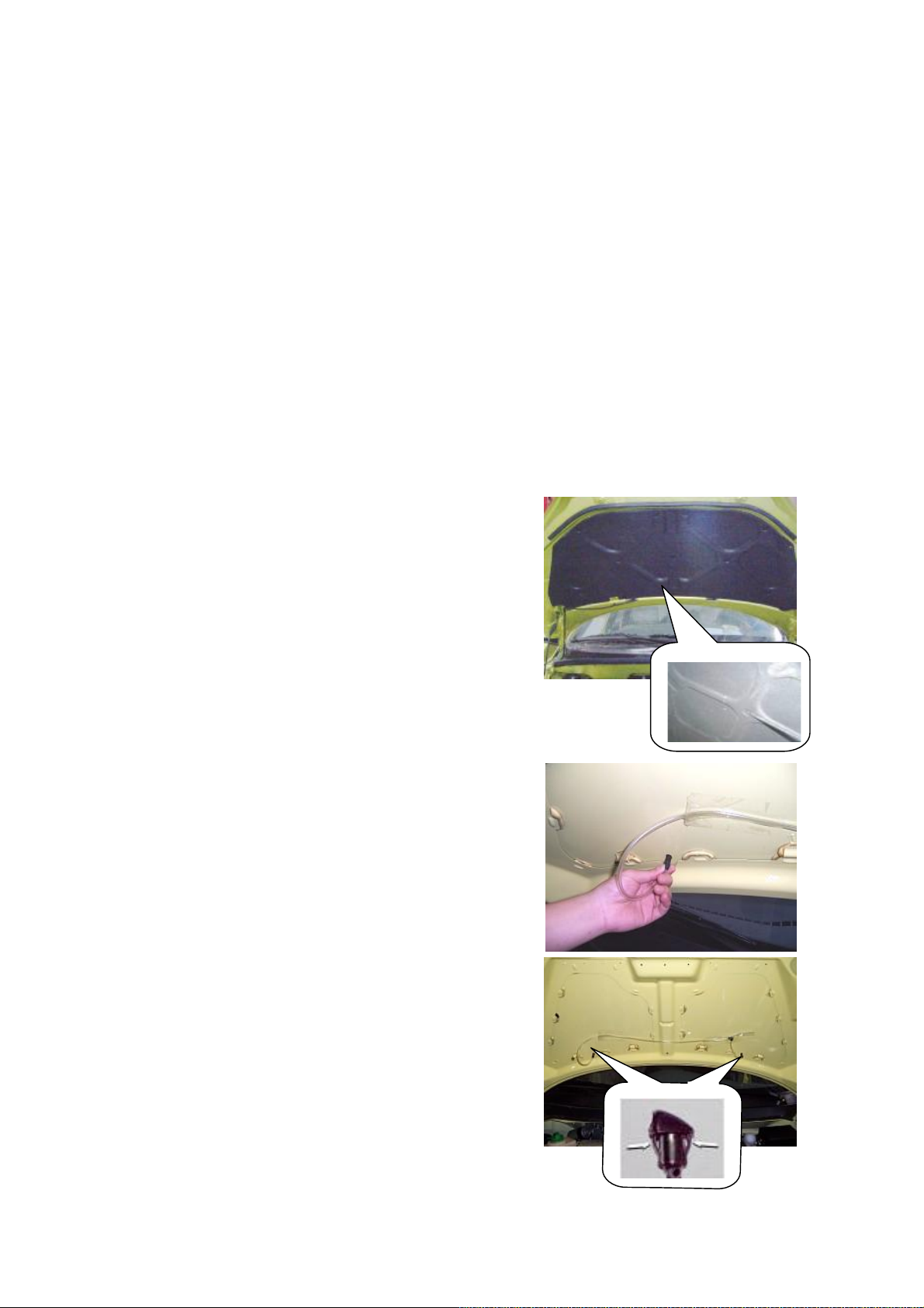
3.1.1. Remove the clip from the heat insulation
washers (19 pcs in total) with a flat head
screwdriver, and detach the heat shield from the
engine compartment.
3.1.2. Pull off the washing liquid hose.
3.1.3. Detach two water spray nozzle clips from
the bottom of engine hood, push the nozzle
from the bottom of engine hood, and take out
the nozzle from the outside.
3.2. Installation Step
The installing steps are reverse to those for
removal.
8
Page 9
4. Disassembly and adjustment of the
engine hood assy.
Preparation of tool(s): 13# wrench
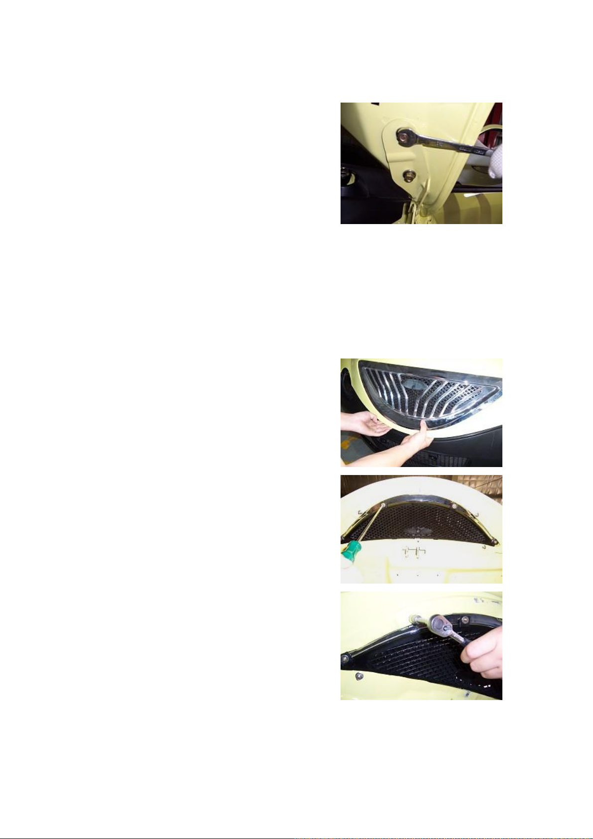
4.1. Take off four adjusting bolts from engine
hood. And remove the engine hood.
At the same time, unscrew four adjusting bolts
to adjust the front/rear position and right/left
position of the engine hood.
4.2. Installation of engine hood assy.:
The installing steps are reverse to those for
removal.
Installation torque is 30±1Nm
5. Disassembly and assembly of air
intake grille assy.
Preparation of tool(s): cross screwdriver, socket
wrench
5.1. Removal Step
5.1.1. Open the engine hood by hand.
5.1.2. Use a cross screwdriver to remove the fix
screw from the intake grille.
5.1.3. Utilize a socket wrench to remove the
fixing bolts from the intake grille.
5.1.4. Detach the intake grille.
5.2. Installation Step
The installing steps are reverse to those for
removal.
Installation torque is 5±1Nm
9
Page 10
6. Adjustment and assembly of the
engine hood lock
Preparation of tool(s): 10# wrench
6.1. Removal Step
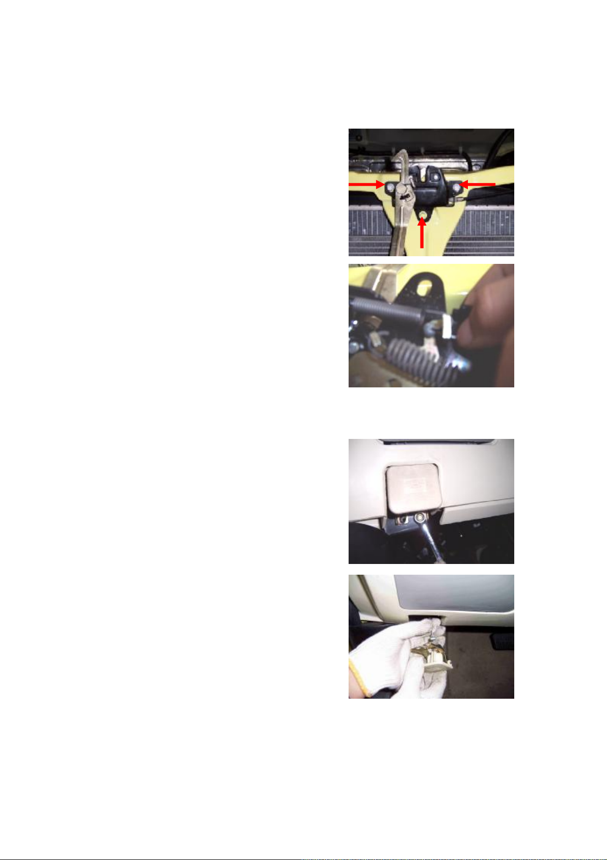
6.1.1. Unscrew three centering bolts from the
engine hood, and then remove the engine hood
lock.
Also unscrew these three bolts to adjust the
position of engine hood lock.
Torque: 9±1 Nm
6.1.2. Remove the lock cable of front engine
hood from engine hood lock assy.
6.2. Installation of engine hood lock
The installing steps are reverse to those for
removal.
Installation torque is 9±1Nm
7. Removal of hood lock control cable
Preparation of tool(s): 8# wrench, 10# wrench,
flat head screwdriver
7.1. Removal Step
7.1.1. Open the engine hood inside the driver’s
cab, and remove two fixing bolts from the
handle.
Installation torque is 9±1Nm
7.1.2. Remove the front hood cable from the
hood.
10
Page 11
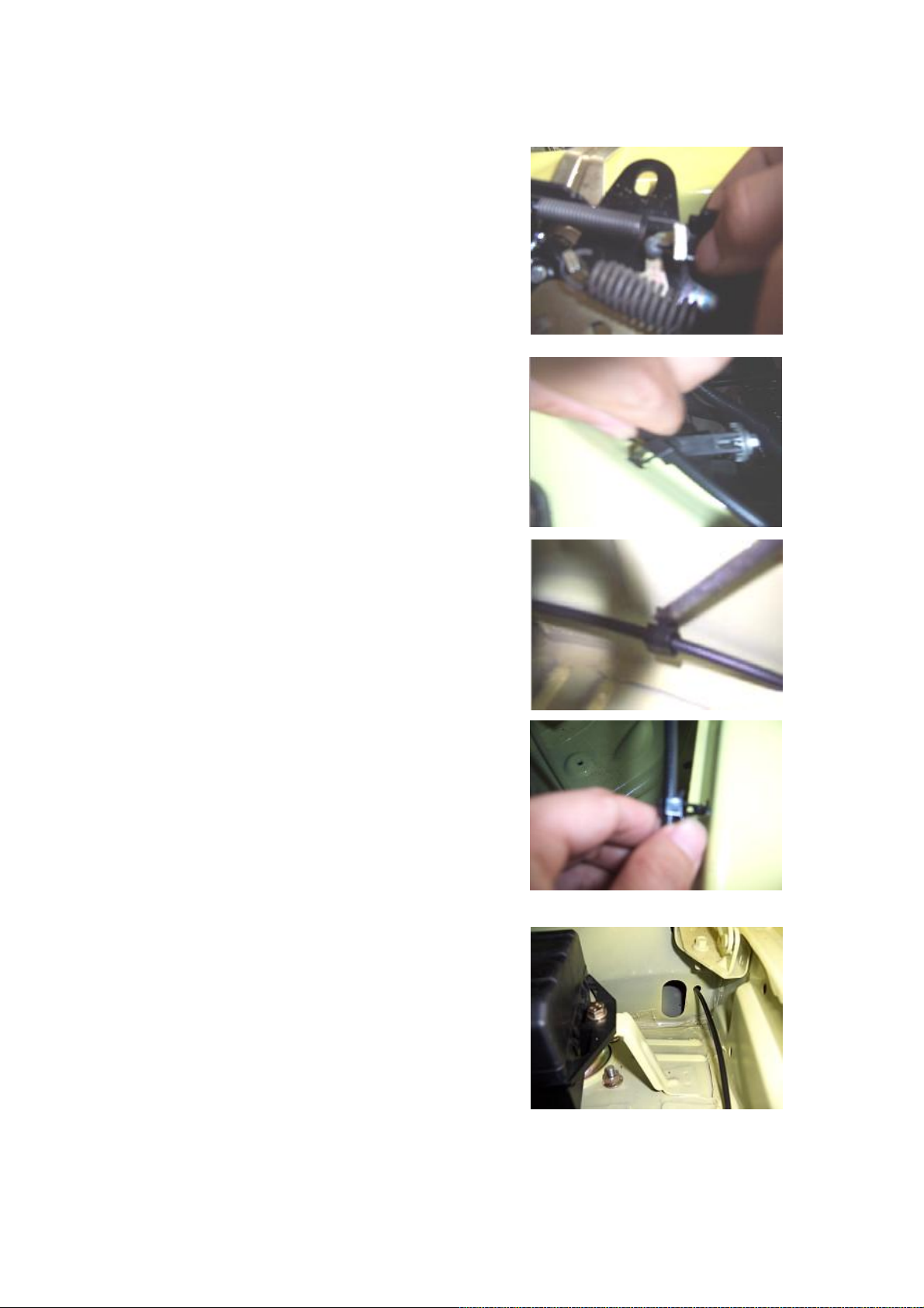
7.1.3. Remove the hood lock and detach the
engine hood lock control cable from the hood
lock assy..
7.1.4. Remove three clips used to fix the control
cable by hand or with a flat head screwdriver.
7.1.5. Draw out the control cable from the
engine compartment.
11
Page 12
7.2. Installation Step
Preparation of tool(s): 10# wrench
The installing steps are reverse to those for
removal.
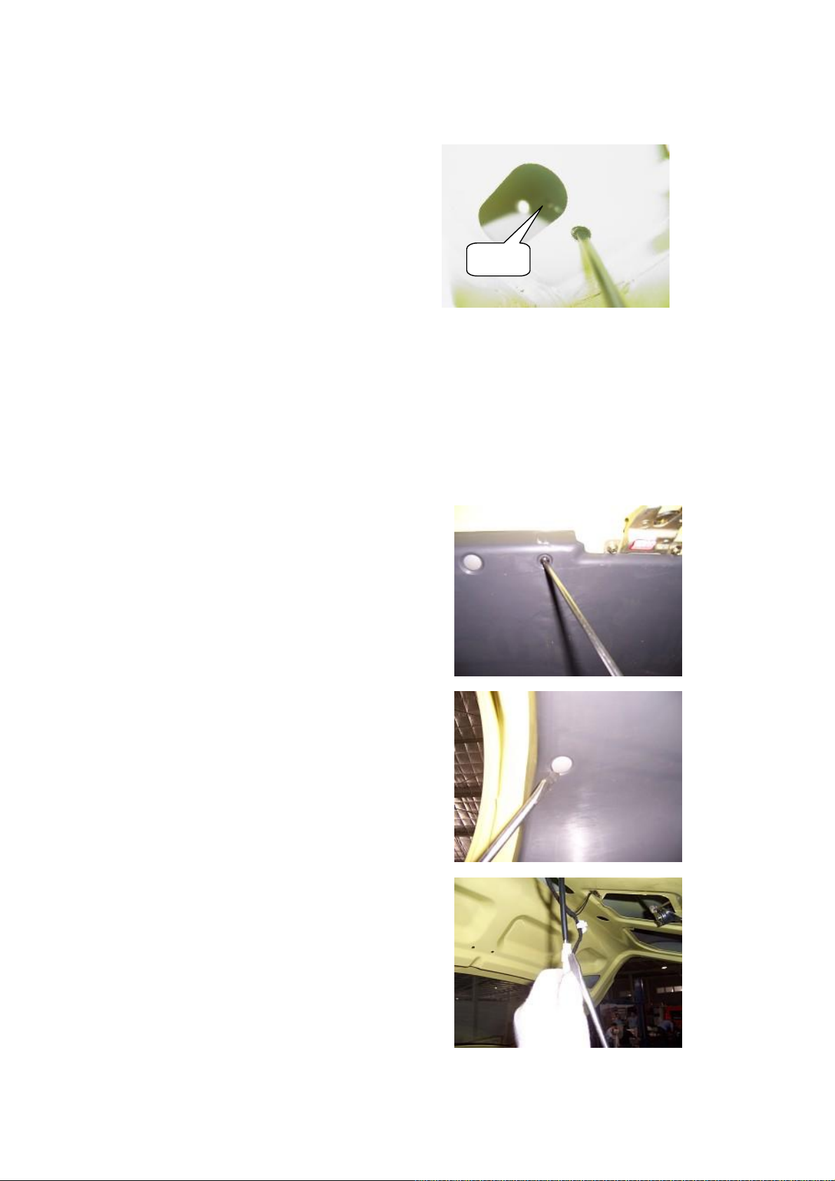
CAUTION: In case of installation, the groove
on control cable shall be inserted into the pull
groove; the control cable penerates into driver’s
cab through the engine compartment, and shall
passes through a small hole and then enters into
the cab, as shown in the figure.
II. Disassembly/Reassembly of
rear boot lid
1. Preparation
Tools: Flat head and cross screwdriver, socket
wrench, open-end wrench
Materials: clip
2. Removal of Trunk Lid Ornament
Plate
Small hole
2.1. Removal Step
2.1.1. Remove the screws from the fixed
luggage boot internal guard plate with a cross
screwdriver.
2.1.2. Remove the disposable clips from the
fixed luggage boot internal guard plate with a
flat head screwdriver, and then remove the
luggage boot internal guard plate.
2.2. Installation Step
The installing steps are reverse to those for
removal.
3. Installation of luggage boot lock
3.1. Removal Step
3.1.1. Detach the connectors of the luggage
boot lock body motor.
12
Page 13

3.1.2. Detach two locating bolts from the
luggage boot lock (the installation torque is 9±1
Nm)
3.1.3. Remove the luggage boot lock core.
3.1.4. Remove two fixing bolts from the trunk
(i.e. luggage boot) lock body with a socket
wrench.
3.1.5. Take off the trunk lock body.
3.2. Installation Step
The installing steps are reverse to those for
removal.
Precautions on installation of luggage boot
lock: check whether the lock column is
deformed, whether the riveted connections are
in its proper positions, and whether the lock
tongue can open or close flexibly, smoothly.
4. Removal of license plate lamp
Preparation of tool(s): cross screwdriver,
open-end wrench.
4.1. Removal Step
4.1.1. Remove the trunk internal ornament plate
(see Removal of trunk lid ornament plate)
4.1.2. Remove two fixing bolts from the license
plate lamp with an open-end wrench.
13
Page 14
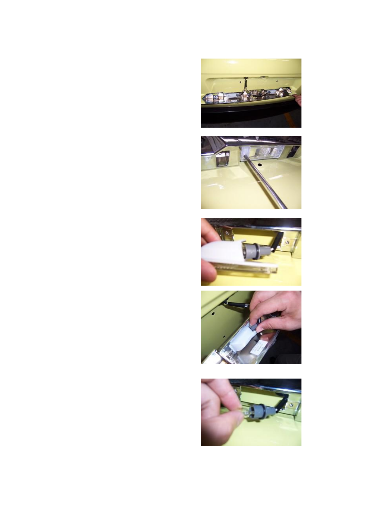
4.1.3. Disconnet the connecting plugs from the
right and left license plate lamps and then take
off the license plate lamp assy.
4.1.4. Remove two fix screws from the license
plate lamp with a cross screwdriver.
4.1.5. Take off the license plate lamp
4.1.6. Take off the bulb from the license plate
lamp.
4.2. Installation Step
The installing steps are reverse to those for
removal.
14
Page 15
Chapter 2 Disassembly/Reassembly of Interior Decorations
I. Disassembly/Reassembly of
Seat Belt
1. Preparation
Tools: flat head screwdriver, wrench, sleeve.
Parts: disposable clips.
2. Precautions
Keep the seat belt clean, avoid the oil stain, and
check whether the seat belt is damaged.
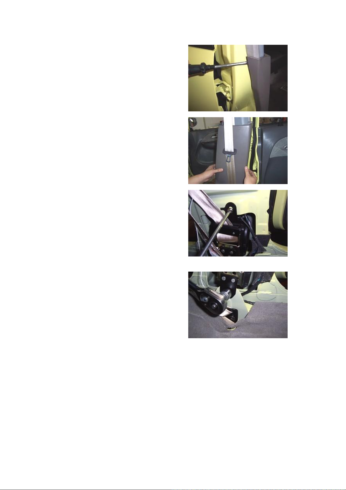
3. Removal Step (Driver’s seat belt is
taken as an example)
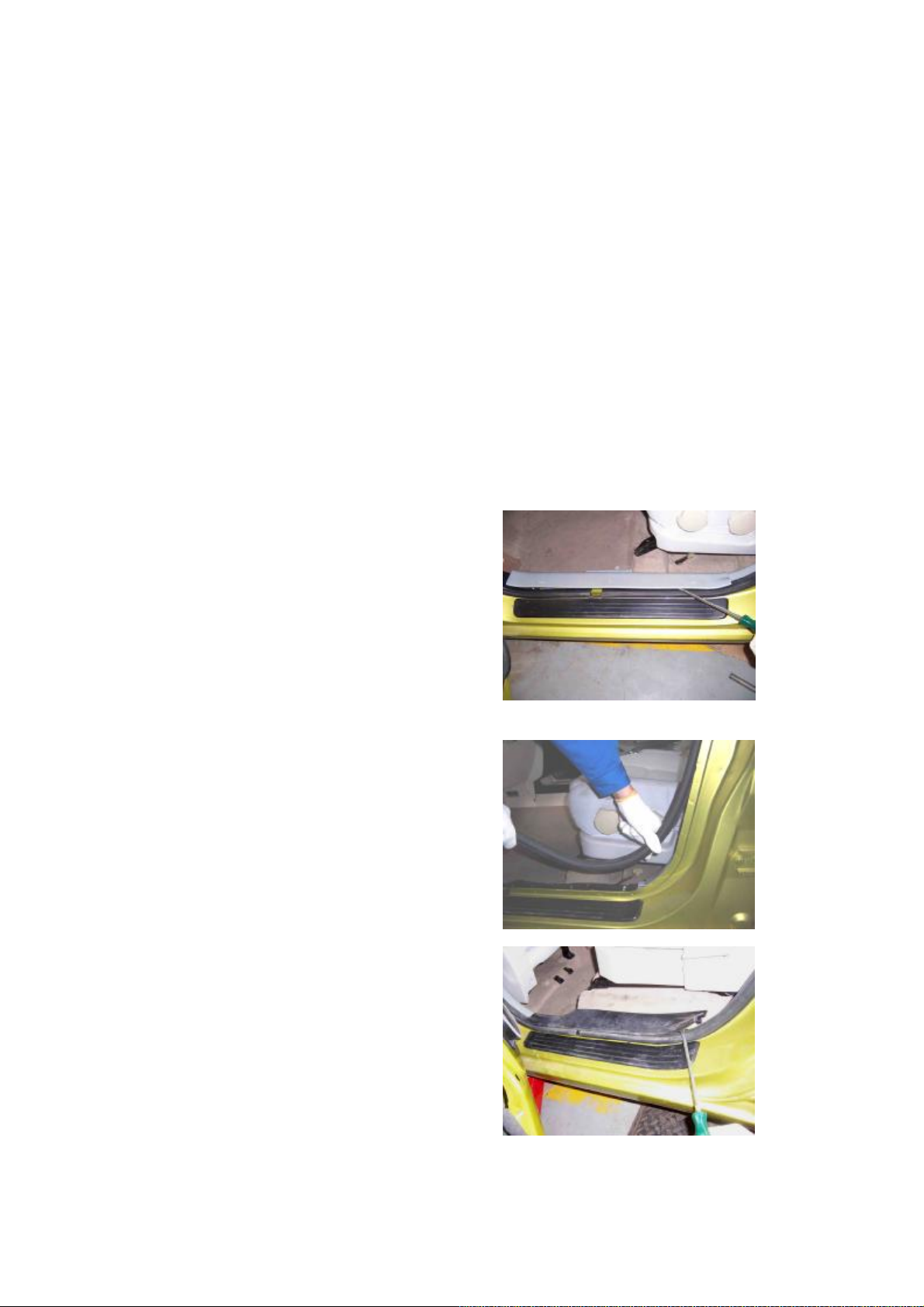
Prize the front threshold pressing plate
carefully with a flat head screwdriver.
3.2. Remove the weatherproof rubber strip of
the front door opening.
3.3. Remove the rear scuff plate.
15
Page 16
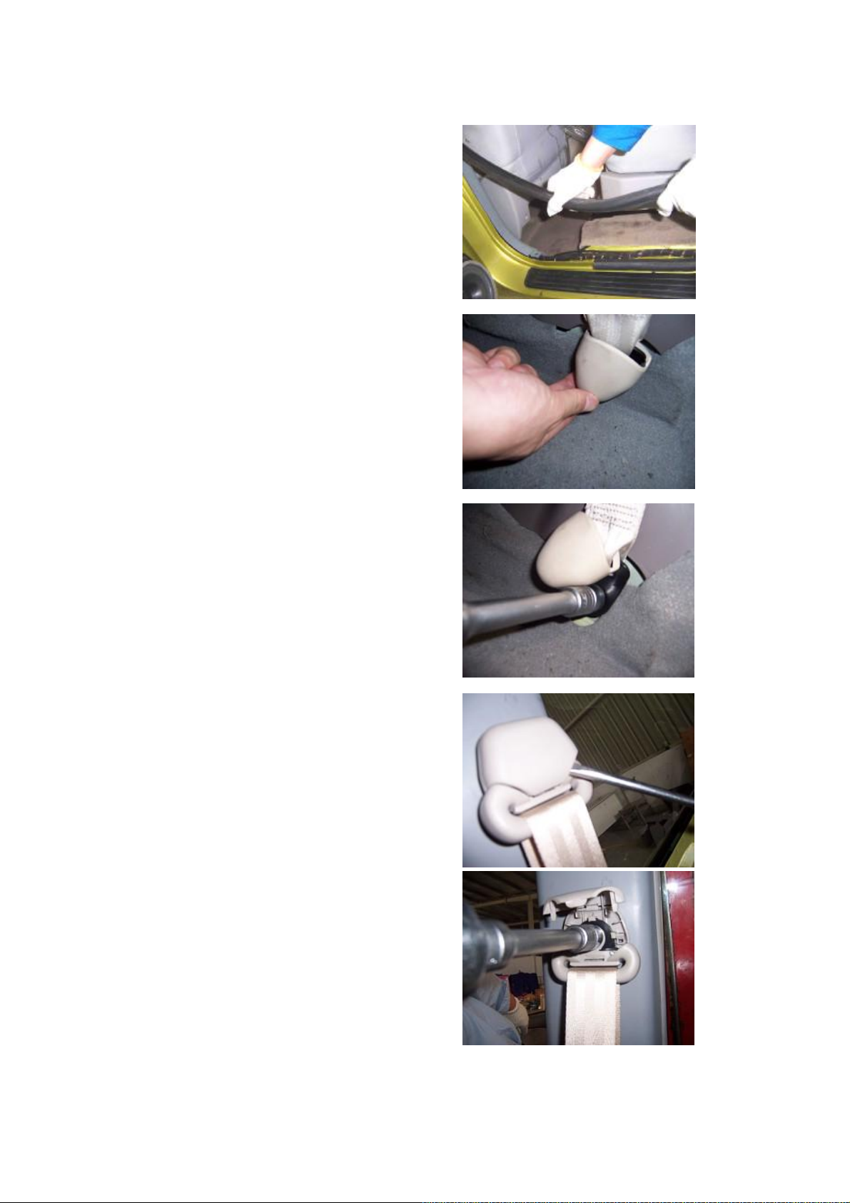
3.4. Remove the weatherproof rubber strip of
the rear door opening.
3.5. Remove the seat belt lower ornament
cover.
3.6. Unscrew the fixing nuts with a 17# sleeve,
and detach the B pillar lower trim.
Installation torque is 50±5Nm
3.7. Unclench the ornament cover on the seat
belt regulator with a flat head screwdriver.
CAUTION: Pay attention to the breakage of
clip inside the regulator.
3.8. Loosen the fixing nuts with a 17# sleeve,
and then take off the seat belt.
Installation torque is 50±5Nm
16
Page 17
fit clearance of lower trim shall be even and
3.9. Unclench the B pillar trim with a
right-angled screwdriver.
3.10. Take off the B pillar trim.
3.11. Remove the fix screws from the seat belt
with a cross screwdriver.
3.12. Loosen the fixing nuts with a 17# sleeve,
and then take off the seat belt.
4. Installation Step
The installing steps are reverse to those for
removal.
Note:
4.1. Keep the seat belt clean, avoid the oil stain,
and check whether the seat belt is damaged.
4.2. The pillar trim shall securely fit with the
body, without any loose symptoms; and the
trim shall fit well with the ceiling and rubber
strip.
4.3. The seat belt adjusting slide baffle on the B
pillar upper trim shall move freely, without any
influence on the adjustment of seat belt, and the
below 1mm;
4.4. The fit clearance between B pillar low trim
and front/rear scuff plate shall be even and less
than 1mm;
17
Page 18
II. Disassembly/Reassembly of
Seat
Tool: 16# sleeve
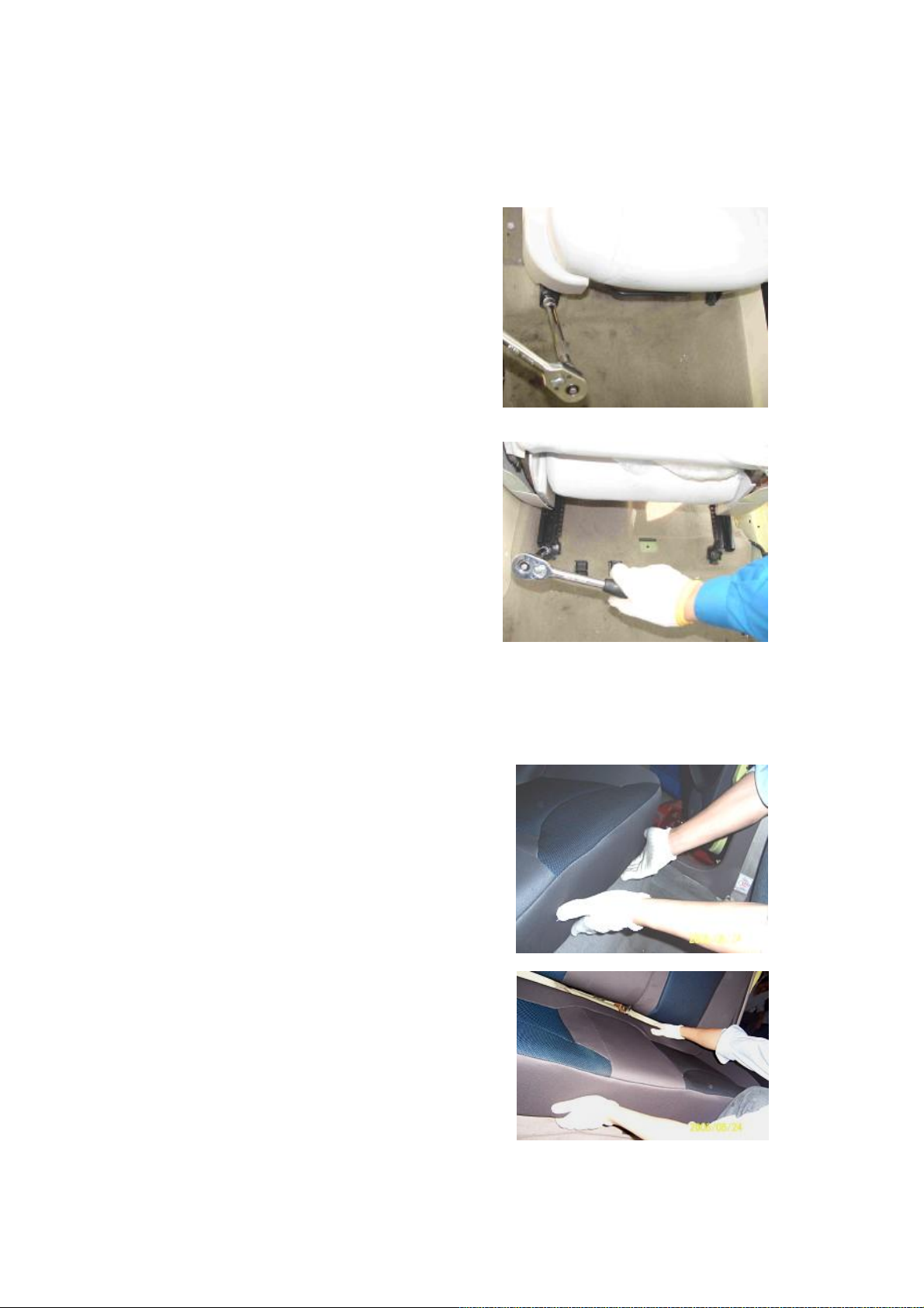
1. Front passenger seat removal step
1.1. Pull the moveable handle under the left
seat to move the left seat backwards and reveal
the fixing bolts under the seat.
1.2. Remove two fixing bolts before the seat.
by sleeve
1.3. Turn the moveable handle and pull
forwards the seat, and expose two fixing bolts
on the rear of seat.
1.4 Disassemble two fixing bolts at the back
of seat with sleeve.
1.5 Pull off the inserter under seat and take
away the seat.
2. Rear passenger seat removal step
2.1 Lift up the rear passenger seat cushion by
hand, and then take out the cushion from the
clips of chassis and body.
2.2. Directly take out the seat cushion by both
hands.
18
Page 19
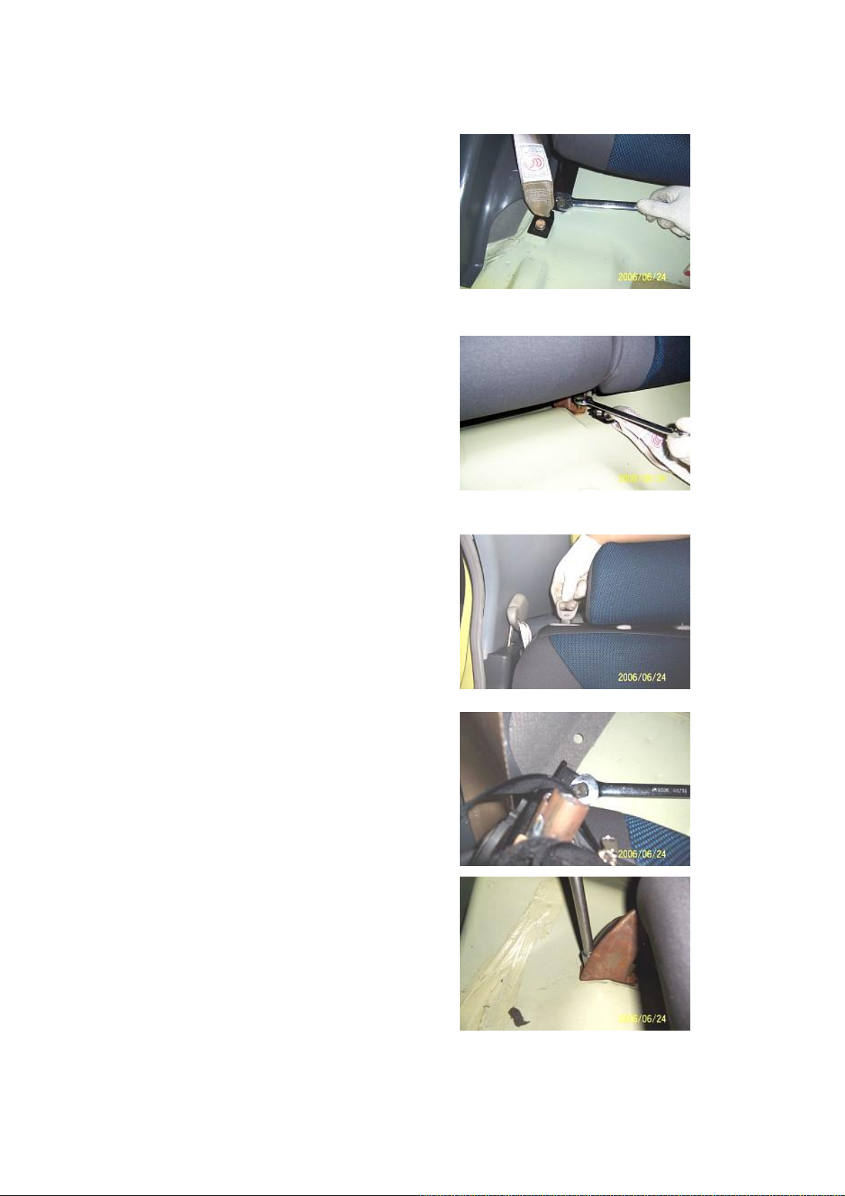
2.3. Loosen the front fixing bolts at the right
side of rear right seat with an open-end wrench.
2.4. Loosen the front fixing bolts at the left
side of rear right seat with an open-end wrench.
2.5. Pull up the ring-pull of rear right seat,
and lay down the seat forwards.
2.6. Loosen the rear fixing bolts at the right side
of rear right seat with an open-end wrench.
2.7. Loosen the rear fixing bolts at the left side
of rear right seat with an open-end wrench, and
then remove the rear right seat.
19
Page 20
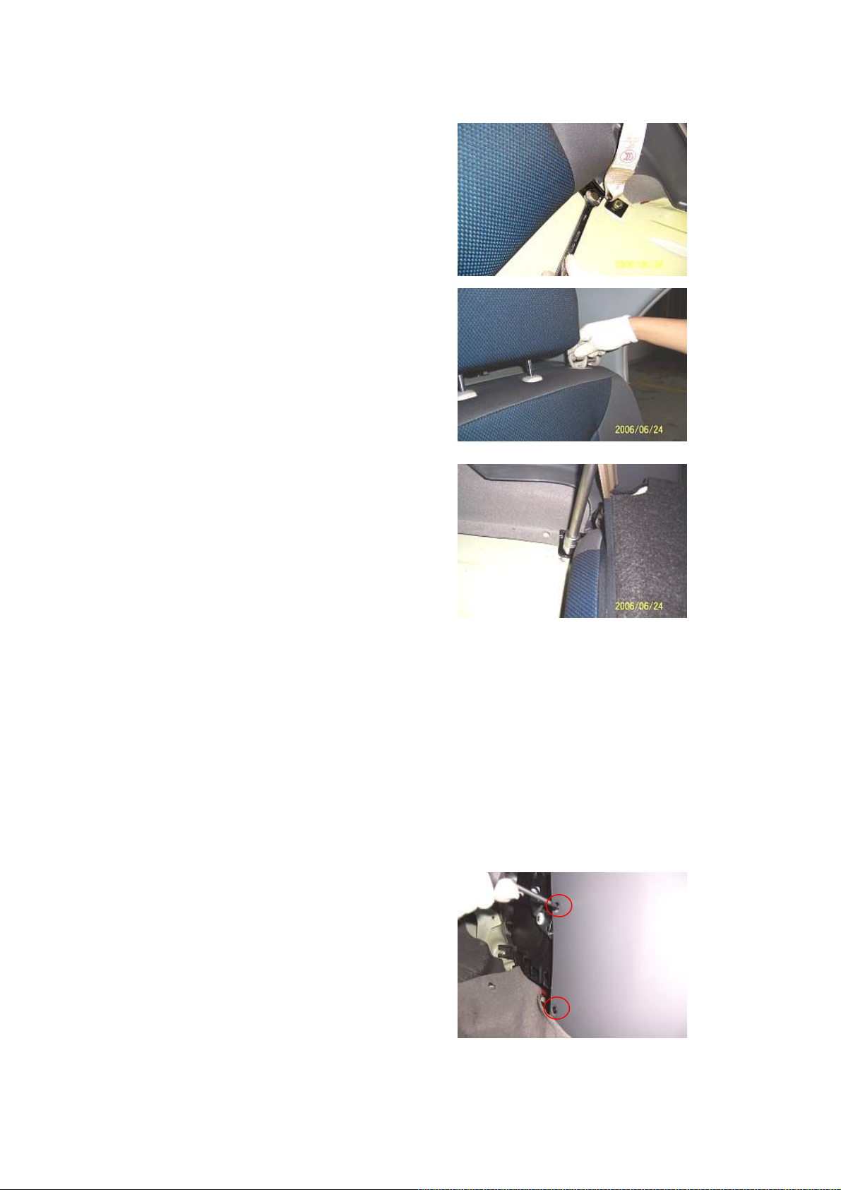
2.8. Loosen the front fixing bolts of rear right
seat with a open-end wrench.
2.9. Pull up the ring-pull of rear left seat, and
lay down the seat forwards.
3.0. Loosen the rear fixing bolt of rear left seat
with a sleeve, and then remove the rear left
seat.
3. Installation Step
The installing steps are reverse to those for
removal.
Installation torque is 25±3Nm
III. Disassembly/Reassembly of
Console
Tool: cross head screwdriver
1. Removal Step
1.1. Remove each two bolts at left and right
sides with a cross screwdriver, these bolts of
which are used to joint the console and front
lower guard plate.
(The tightening torque is 2±0.5N.m)
20
Page 21
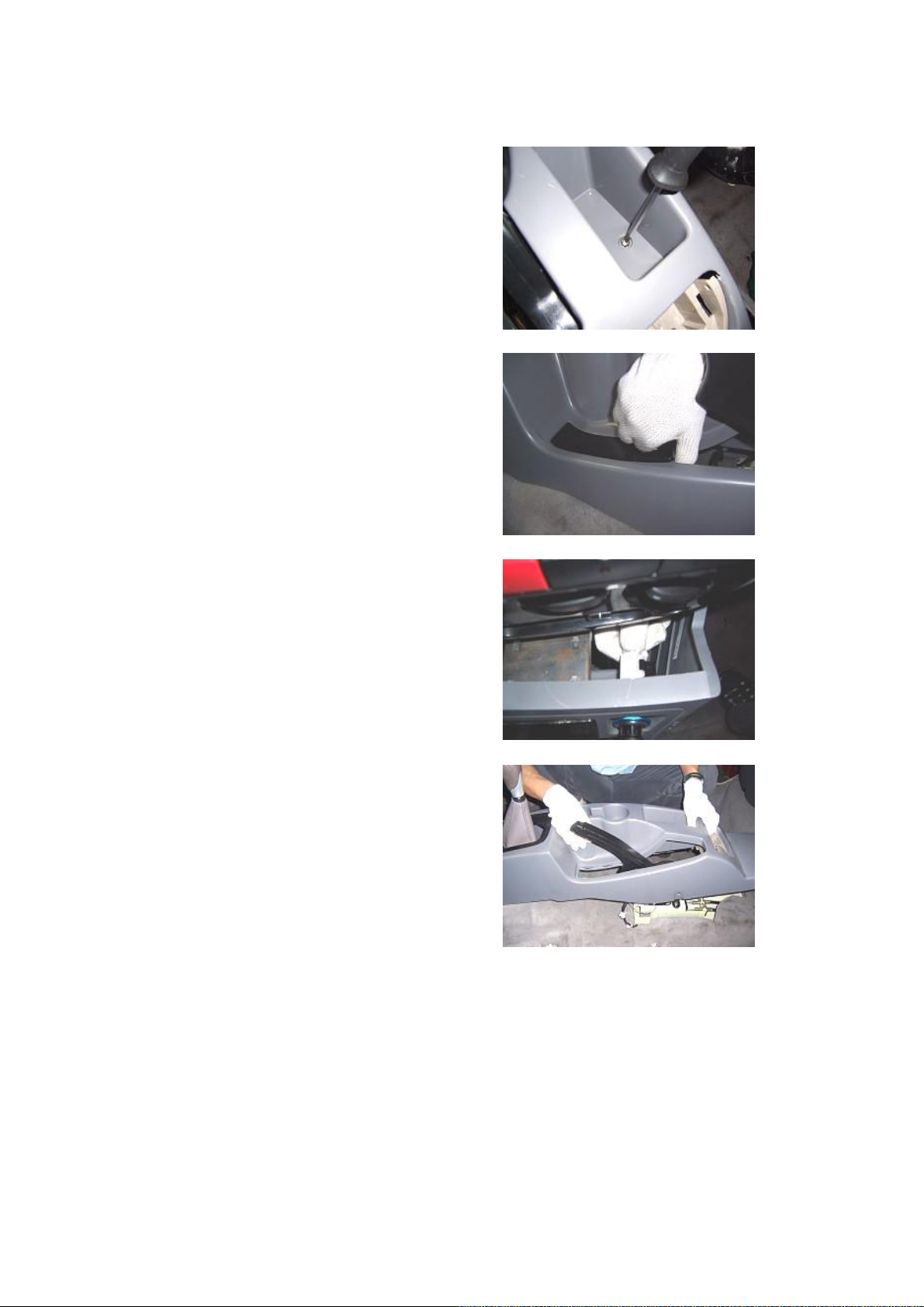
1.2. Remove the bolts used to joint the console
and body lower guard plate with a cross
screwdriver.
(The tightening torque is 2±0.5N.m)
1.3. Detach the console hand brake ornament
plate by hand.
1.4. Pull out the cigarette lighter plug on the
console by hand.
1.5. Take off the console.
2. Installation Step
The installing steps are reverse to those for
removal.
21
Page 22

IV. Disassembly/Reassembly of
Carpet
Tool: flat head screwdriver, cross head
screwdriver; sleeve
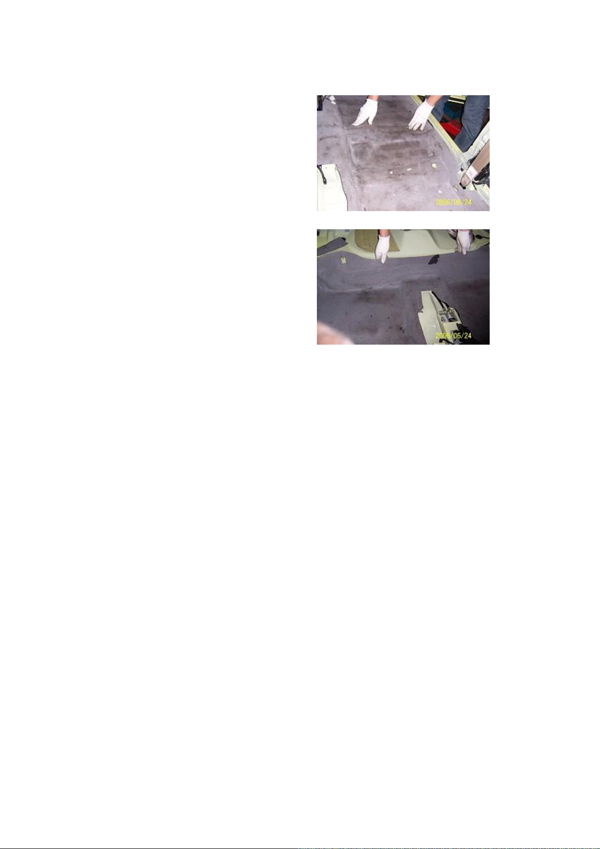
1. Removal Step
1.1. Remove the seat. (See Disassembly of
Seat)
1.2. Remove the scuff plate, lower trims of B
and C pillars.
(See Disassembly of B and C Pillars)
1.3. Remove the A pillar lower trim.
1.4. Remove the armrest box and console. (See
Disassembly of Armrest Box and Console)
1.5. Prize the cover on the driver pedal with flat
head screwdriver.
1.6. Remove two fixing nuts from the driver’s
pedal with a socket wrench, and then take off
the pedal.
Installation torque: 7±1N.m
1.7 Take off the carpet after Pull off the carpet
connectors
2. Installation Step
2.1. Place the carpet into the vehicle, tightedly
press the carpet near the central passage, and
expose the corresponding hole from the carpet
hole, and lay the carpet reliably.
2.2. Lay the left central rear part of carpet
according to the shape of the vehicle bottom,
and reveal the installation holes of front left
seat and lay the carpet reliably.
22
Page 23
2.3. Lay the right central rear part of carpet
according to the shape of the vehicle bottom,
and reveal the installation holes of front right
rear seat and lay the carpet reliably.
2.4. Lay well the rear part of carpet according
to the shape of vehicle bottom.
V. Removal of Cushion Pad
1. Removal Step
1.1. Disassemble the carpet (See disassembly of
carpet)
1.2. Take off all cushion pads.
23
Page 24

2. Installation Step
2.1. The installing steps are reverse to those for
removal.
2.2. Precautions on reassembly of cushion pad:
2.2.1. Take out the connector harness from the
seat and rear oxygen sensors when the cushion
pad is laid.
2.2.2. Make the shock absorber lower surface
joint tightly with plate work.
24
Page 25
Chapter 3 Removal and Maintenance of Door
I. Disassembly/Reassembly and Maitenance of Front Door
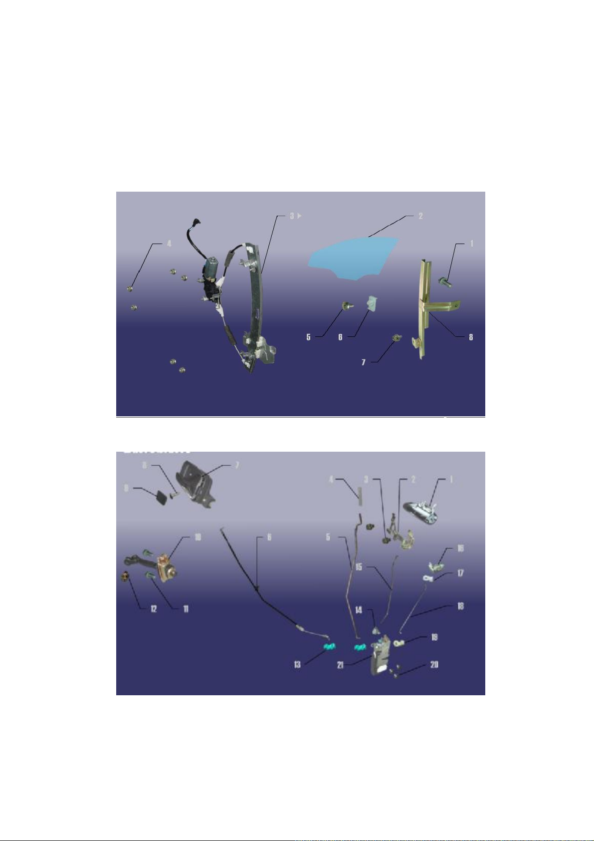
1. System Composition Diagram
25
Page 26
2. Preparation
Tools: right-angled screwdriver, cross
screwdriver, 7#, 10# and 13# sleeves, plier.
3. Precautions
3.1 Please wear necessary labor protection
supplies to avoid accidents.
3.2 Power off accumulator to avoid damage the
electrical units.
3.3 Use the correct method to disassemble and
assemble the glass to avoid damage.
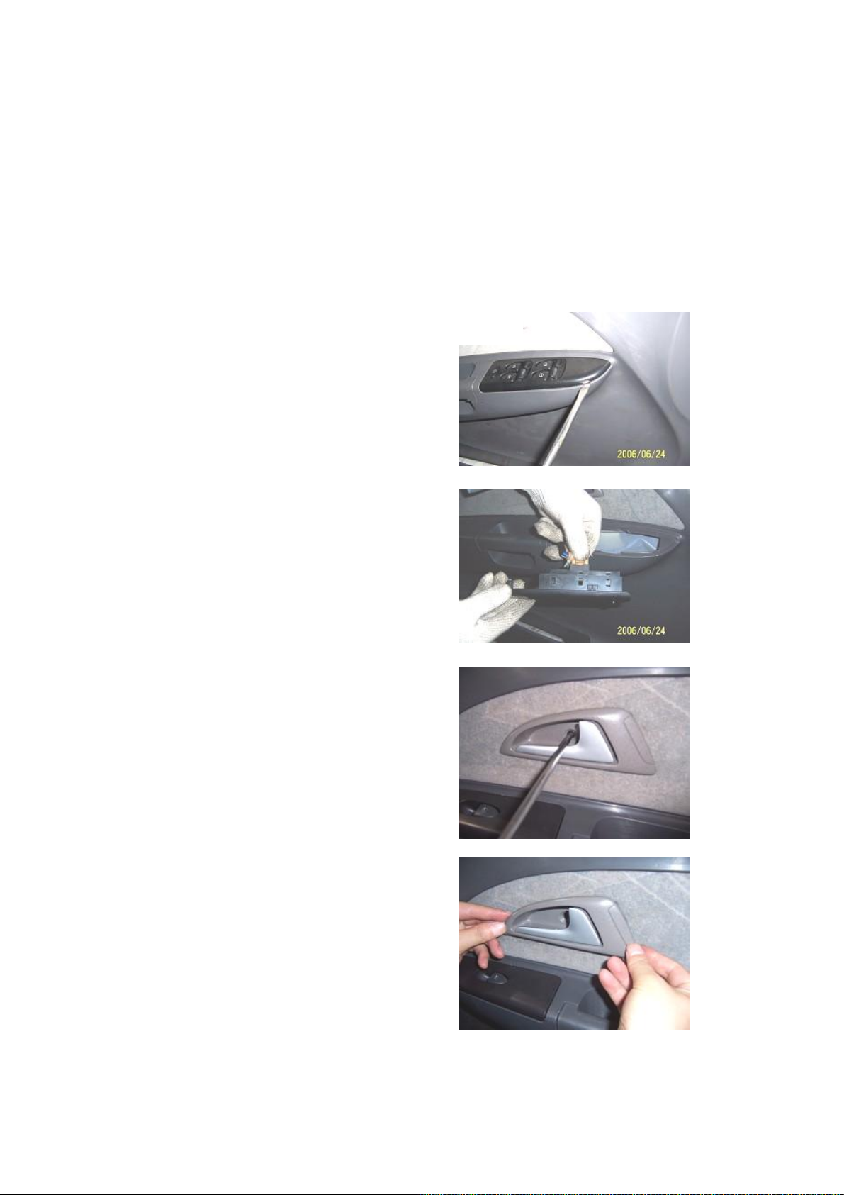
4. Disassembly/Reassembly Step
4.1. Unclench the protecting cover of glass
drive switch on the door inner guard plate with
a right-angled screwdriver.
4.2. Pull out the connector from the glass drive
switch by hand..
4.3. Unscrew the fix screws of front door inner
handle with a cross screwdriver.
4.4. Take off the inner handle frame by both
hands.
26
Page 27
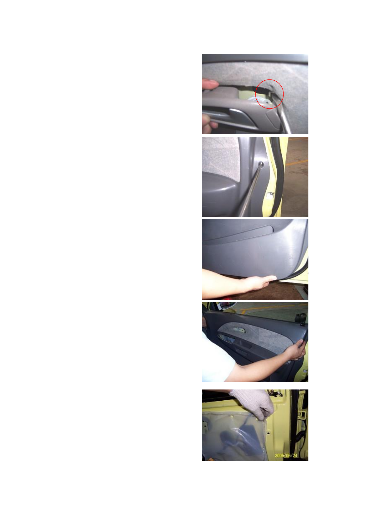
4.5. Separate the inner bar from the inner
handle with a right-angled screwdriver.
4.6. Remove the fix screws from the front door
inner guard plate with a cross screwdriver.
4.7. Lift up the door inner guard plate from the
lower to upper by both hands.
4.8. Directly take out the door inner guard plate
by both hands.
4.9. Tear down front door water-proof plastic
clothing.
27
Page 28
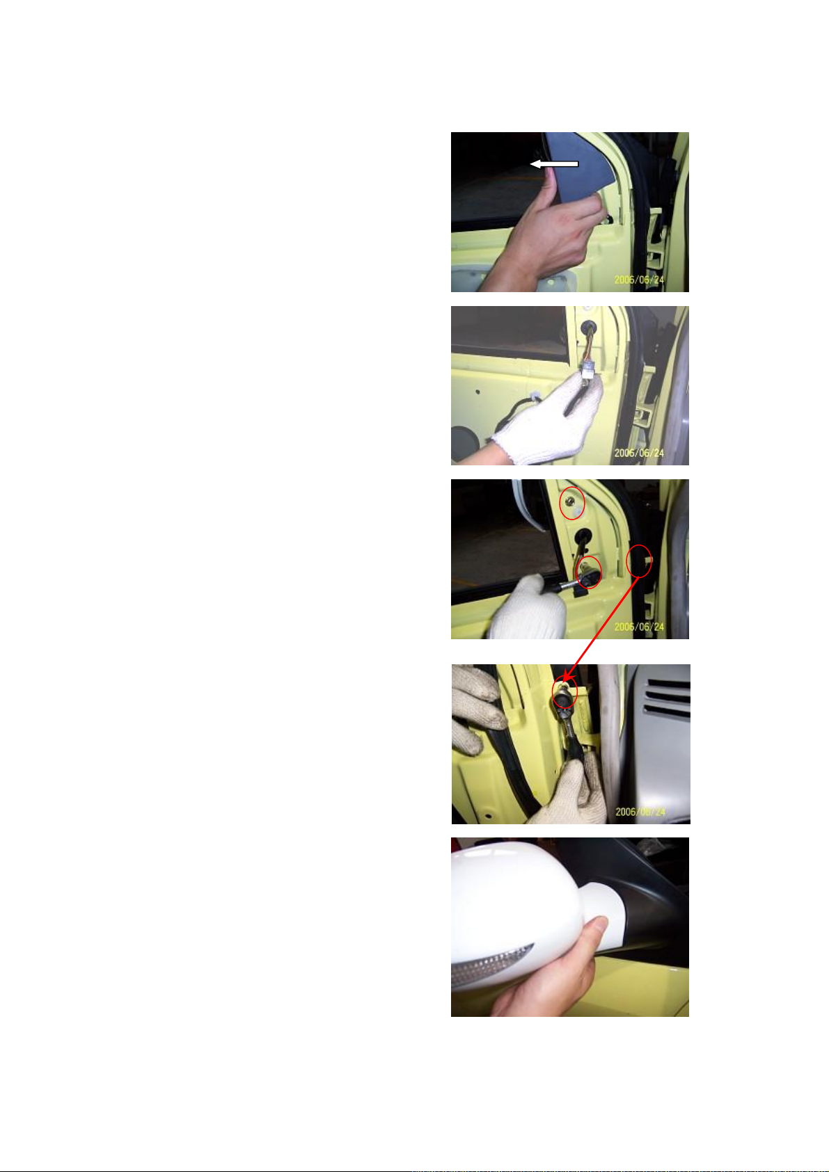
4.10. Take off the interior set square of the
exterior rear-view mirror by hand.
4.11. Pull out the connector of the exterior
rear-view mirror by hand.
4.12. Remove three fix screws from the exterior
rear-view mirror with a sleeve.
4.13 Remove three fix screws from the exterior
rear-view mirror with a sleeve.
4.14 Take off the exterior rear-view mirror assy
by hand.
28
Page 29
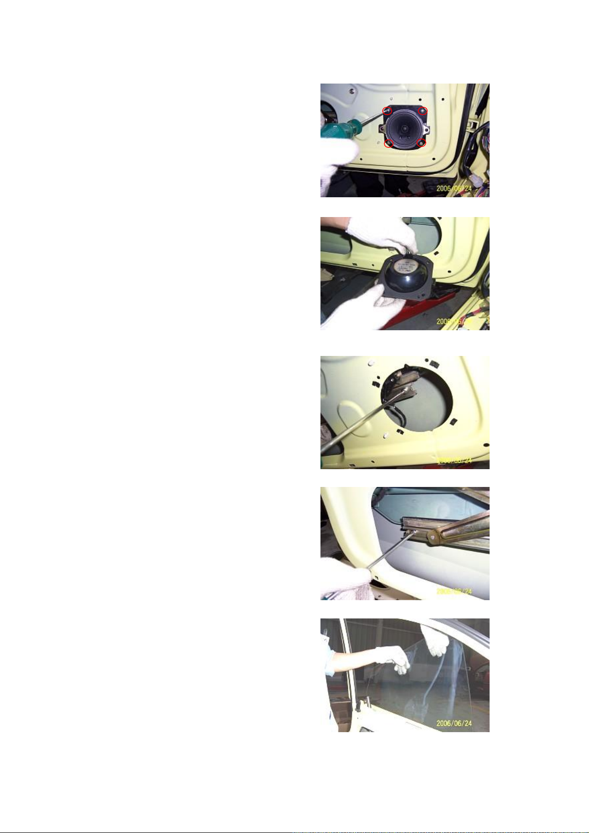
4.15. Unscrew four fixing screws from front
door sound box by cross head screwdriver.
Take out sound box assy.
4.16 Pull out the connector of the front door
sound box.
4.17 Reinsert the glass drive switch into the
harness, and descend the front door glass down
to its lowest position.
4.18. Loose two fixing screws on the glass by
cross head screwdriver.
And take out the glass assembly.
Torque: 4.5±0.5 N.m.
4.19 When the glass assy is being taken, erect
the glass assy so as to easily take off it.
29
Page 30
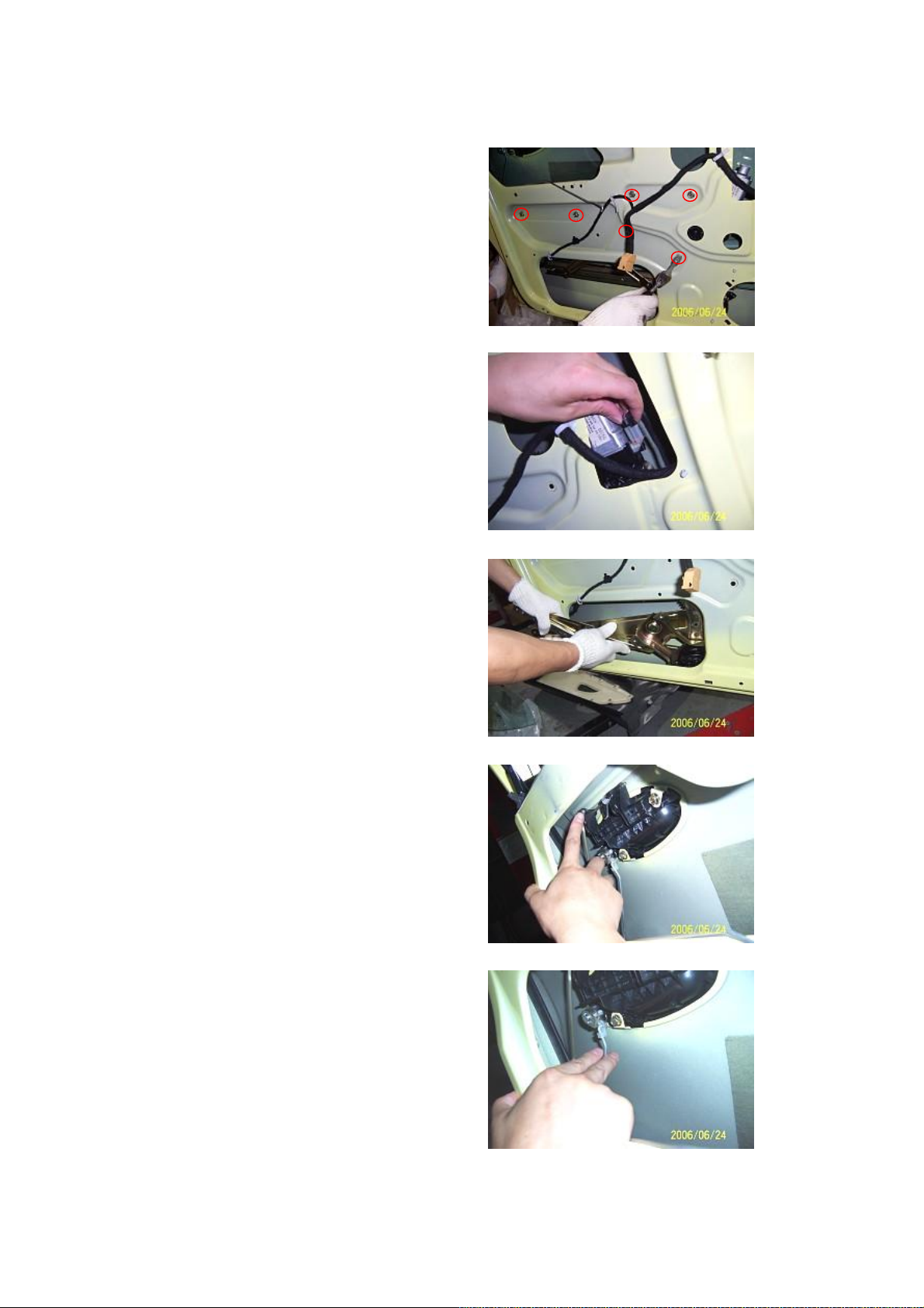
4.20 Remove six fixing bolts from the window
glass regulator with a 10# sleeve.
Torque: 9±1 N·m.
4.21 Pull out the connector of window glass
regulator by hand.
4.22 Take off the window glass regulator assy.
4.23 Separate the upper fixing clips of front
door lock core rod from the lock by hand.
4.24 Separate the lower fixing clips of front
door lock core rod from the lock by hand.
30
Page 31

4.25 Loosen the fix screws of front door
exterior handle with a sleeve.
4.26. Take out lock core and handle assy.
4.27 Remove three fix screws from the front
door lock core with a cross screwdriver.
Installation torque: 9±1 Nm
4.28 Pull out the fastener connector and then
take off the fastener.
4.29 Loosen two upper fixing bolts of front
door hinge from the door with a 13# wrench.
Torque: 36±4N.m.
31
Page 32

4.30 Loosen two lower fixing bolts of front
door hinge from the door with a 13# wrench.
Torque: 36±4N.m.
4.31 Remove the fixing bolts of door limiter
from the door with a 10# sleeve.
Torque: 10±1 N.m
4.32 Remove the fixing bolts of door limiter
from the body with a 10# sleeve, and then take
off the door limiter.
Torque: 10±1 N.m
4.33 Pull out the door harness, and then take off
the door body.
32
Page 33

5. Installation and Adjustment Step
5.1. The installing steps are reverse to those for
removal.
5.2. Adjustment of door
5.2.1. After the installation of door, check the
horizontial and vertical clearances and the
closing force of door. If the clearance is
incorrect and the closing force is big, timely
adjust the clearnace and force. See Body
Dimension for the adjustment of door
clearance.
5.2.2. The door clearance is adjusted by
regulating the fixing bolts of hinge at the body.
5.2.3. The closing force of door can be slightly
adjusted by regulating the position of front door
lock column.
Torque: 9±1Nm.
5.3. Adjustment of door glass regulator system.
5.3.1. Check the window regulator system after
this system is assembled. The duration of
window glass lifting from the lowest position to
the highest position shall be approximate 7 s.
If the time is too long, check the regulator in
time.
5.3.2 Check window regulator motor.
5.3.3. Check whether there is oil or dust in the
glass run channel which may result that the
resistance is overhigh when the window glass is
rising.
CAUTION: DO NOT apply any lubricating
grease on the glass run channel or glass so as to
avoid the adhesion of dust.
5.3.4. Check whether the installation of glass
guide is deviated from its proper position,
which may result that the glass is clamped due
to the nonuniform arc scale when the glass is
rising. The position of glass guide can be
adjusted by the guide fixing bolts.
33
Page 34

II. Disassembly/Reassembly and
Maintenance of Rear Door
1. Preparation
Flat head screwdriver, cross head screwdriver,
No.7, 10, 13 sleeves and pliers.
2. Precautions
2.1 Please wear necessary labor protection
supplies to avoid accidents.
2.2 Power off accumulator to avoid damage the
electrical units.
2.3 Use the correct method to disassemble and
assemble the glass to avoid damage.
3. Removal Step
3.1. Prize two rear door glass slot protecting
boards with flat head screwdriver.
(See front door disassembly to disassemble
weather strip)
3.2. Unscew the fix screws of rear door inner
handle with a cross screwdriver.
3.3. Take off the inner handle frame by both
hands.
3.4. Separate the inner bar from the inner
handle with a right-angled screwdriver.
34
Page 35

3.5. Unclench the protecting cover of glass
drive switch from the door inner guard plate
with a right-angled screwdriver.
3.6. Pull out the connector of glass drive switch
by hand.
3.7. Remove the fix screws from the front door
inner guard plate with a cross screwdriver.
3.8. Directly take off the door inner guard plate
by both hands.
3.9. Tear down front door water proof plastic
clothing.
35
Page 36

3.10. Unscrew four fixing screws from front
door sound box with cross head screwdriver.
Take out sound box assembly.
3.11. Pull out the connector of front door sound
box.
3.12. Reinsert the glass drive switch into the
harness, and then descend the front door
window glass down to its lowest position.
3.13 Loosen two fixing screws on the glass
with cross head screwdriver.
And take out the glass assembly.
Torque: 4.5±0.5 N.m.
3.14. When the glass assy is being taken, erect
the glass assy so as to easily take off it.
36
Page 37

3.15. Remove six fixing bolts from the window
glass regulator with a 10# sleeve.
Torque: 7±1 N·m.
3.16. Pull out the connector of window glass
regulator by hand.
3.17. Take off the window glass regulator assy.
3.18. Push aside the fixed mounting of lock
core rod from the door with a right-angled
screwdriver.
3.19. Separate the fixing clips of lock core rod
from the lock by hand.
37
Page 38

3.20. Take off the lock core rod by hand.
3.21. Separate the upper fixing clips of front
door lock core rod from the lock by hand.
3.22. Separate the lower fixing clips of front
door lock core rod from the lock by hand.
3.23. Loosen the fix screws of front door
exterior handle with a cross screwdriver.
3.24. Take out lock core and handle assy.
38
Page 39

3.25. Remove three fix screws from the front
door lock with a cross screwdriver.
3.26. Pull out the fastener connector, and then
take off the fastener.
3.27. Remove the fixing bolt from the door
limiter with a 10# sleeve.
Torque: 10±1 N.m
3.28. Remove the other fixing bolt from the
door limiter with a 10# sleeve, and then take off
the door limiter.
Torque: 10±1 N.m
3.29. Loosen two upper fixing bolts of front
door hinge from the door with a 13# wrench.
Torque: 36±4N.m.
39
Page 40

3.30. Loosen two lower fixing bolts of front
door hinge from the door with a 13# wrench.
Torque: 36±4N.m.
3.31 Pull out the door harness, and then take off
the door body.
4. Installation and Adjustment Step
4.1. The installing steps are reverse to those for
removal.
4.2. Adjustment of door
4.1.1 Rear door clearance can not be adjusted
by hinge adjustment. If the door clearance is
improper, correct the body only to ensure the
clearance.
(See Body Dimension)
4.1.2 Please refer to Front Door Adjustment.
40
Page 41

Chapter 4 Disassembly/Reassembly and Maintenance of
Front/Rear Bumper
I. Disassembly/Reassembly and Maintenance of Front Bumper
1. System Composition Diagram
Front/Rear Bumper
2. Preparation
No.7 and No10 sleeve, cross head screwdriver and flat head screwdriver.
3. Precautions
3.1. Please wear necessary labor protection supplies to avoid accidents.
3.2. To prevent scratch the bumper surface paint.
3.3. Carry out the disassembly and assembly at low temperature environment, do not use big force,
otherwise the bumper will be broken.
41
Page 42

4. Removal Step
4.1 Open the front engine hood by hand.
4.2 Loosen the fixing bolts of front bumper
from the right and left sides of radiator cross
beam with a 10# sleeve. (The left side is taken
as an example)
Torque: 11N·m
4.3 Loosen the fixing bolts of front bumper
from the intermediate part of radiator cross
beam with a 10# sleeve.
Torque: 11N·m
4.4 Loosen two fixing bolts under the bumper
from the mud guard with a 7# sleeve.
Installation torque: 2±0.5 Nm
4.5. Unscrew mudguard fixing bolt beside the
bumper with No.7 sleeve.
Installation torque: 2±0.5N.m
42
Page 43

4.6 Remove the fixing bolts of mud guard from
the side of bumper with a cross screwdriver.
4.7 Pull out the bumper from the fixed
mounting at the fender by hand.
4.8. Pull out fog lamp plug by hand, and take
out bumper assy.
4.9 Remove three screws applied to joint the
fog lamp and bumper with a cross screwdriver.
4.10 Remove the bumper body assy.
43
Page 44

4.11 Loosen three fixing bolts and a fixing nut
used to secure the front bumper stiffening beam
with a 13# sleeve.
Torque: 25±3N.m
4.12 Loosen intake grille fixing screws from
both sides of bumper with a cross screwdriver.
5. Installation and Maintenance
5.1. The installing steps are reverse to those for
removal.
44
Page 45

II. Disassembly/Reassembly and Maintenance of Rear Bumper
1. System Composition Diagram
Front/Rear Bumper
2. Preparation
Tools: cross screwdriver, 7# sleeve.
3. Precautions
3.1. Please wear necessary labor protection supplies to avoid accidents.
3.2. To prevent scratch the bumper surface paint.
3.3. When the rear bumper is disassembled/reassembled in the low temperature environment, the
force applied can’t be big so as to avoid the breakage of the bumper.
45
Page 46

4. Removal Step
4.1. Open the luggage boot lid, and loosen two
fixing clips from the rear bumper with a cross
screwdriver. See right figure.
4.2. Loosen the fix screws and clips of rear
bumper and rear mud guard with a 7# sleeve.
Torque: 7N·m
4.3. Loosen the fix screws at the left side of
rear mud guard and rear bumper with a 7#
sleeve.
4.4. Loosen the fix screws at the right side of
rear mud guard and rear bumper with a 7#
sleeve.
4.5. Push out the fixing clips of rear bumper
from the rear mud guard by hand.
46
Page 47

4.6 Pull out the bumper from the fixed
mounting at the fender by hand.
4.7. Take off rear bumper assy.
5. Installation Step
The installing steps are reverse to those for
removal.
47
Page 48

Chapter 5 Disassembly/Reassembly and Maintenance of
Headlamp and Fog Lamp
1. System Composition Diagram
Lamp
48
Page 49

2. Preparation
No.10 sleeve and No.7 open end wrench, cross
head screwdriver and flat head screwdriver.
3. Precautions
3.1 Please wear necessary labor protection
supplies to avoid accidents.
3.2 To prevent scratch the bumper surface
paint.
3.3. In case of disassembly/reassembly in the
low temperature environment, the force applied
can’t be big so as to avoid the breakage of the
bumper. Disconnect the control switch of
corresponding lamps, and remove the wire
connected to the battery.
3.4. When the headlamp is being removed, pay
more attention to its clips on the bumper. The
big force may damage the clips.
3.5 Pay attention to not scratch the headlamp
surface when disassemble and place.
4. Removal Step of Headlamp
4.1. Disassemble front bumper assy first. (See
disassembly/assembly of bumper)
4.2. Loosen headlamp two fixing bolts on
engine hood cross beam with No.10 sleeve.
Torque: 3.5±0.5N·m
49
Page 50

4.3. Remove the fixing bolts under the
headlamp with a cross screwdriver.
Torque: 1.8±0.2N·m
4.4. Pull out the plug from the headlamp, and
then take off the headlamp assy.
4.5. Open the lamp holder clips by hand.
4.6. Pull out two harness connectors by hand.
4.7. Remove two fix screws with a cross
screwdriver.
50
Page 51

4.8. Hold the bulb seat by hand, and take off the
bulb from the headlamp.
CAUTION: In case that the bulb is replaced,
DO NOT contact the bulb by hand, otherwise
the fingerprint remained on the bulb is heated
and volatilzes after the lamp lights, and then
deposits on the mirror surface, which may
result that the reflector darkens.
4.9. Screw off headlamp high beam seat cover.
4.10. Pull out two harness connectors by hand.
4.11. Remove two fix screws with a cross
screwdriver.
51
Page 52

4.12. Hold the bulb seat by hand, and take off
the bulb from the headlamp.
CAUTION: In case that the bulb is replaced,
DO NOT contact the bulb by hand, otherwise
the fingerprint remained on the bulb is heated
and volatilzes after the lamp lights, and then
deposits on the mirror surface, which may
result that the reflector darkens.
5. Removal of Fog Lamp
5.1. Remove the bumper assy. Refer to
Disassembly of Bumper.
5.2. Pull out the plug of fog lamp.
5.3. Unscrew three fixing nuts from the fog
lamp with a cross screwdriver.
5.4 Take off the fog lamp assy.
52
Page 53

6. Installation and Adjustment of
Headlamp
6.1. headlamp Installation Step
The installing steps of headlamp are
reverse to those for removal.
6.2. Introduction to headlamp function
6.2.1. Front view
See right figure:
1 Low beam light
2 Position light
3 High beam
4 Turn light
6.2.2. Back view
See right figure:
1 Low beam light
holder
2 Headlamp’s plug
3 High beam light
holder
4 High beam up/down
adjusting nut
5 High beam left/right adjusting nut
6 Low beam up/down adjusting nut
7 Low beam left/right adjusting nut
6.3. Adjustment of headlamp light
7
1
1
6
2
5
2
4
3
3
4
Headlamp uses half closed light combination type. So it is easy to be maintained; it is halogen
light with less mechanism and high luminous intensity, which will prolong bulb life.
The correctness of headlamp adjustment will influence the driving safety. So it needs special
device to adjust the beam. Pay attention to law regulations and verify the following items before
adjustment:
a. Tire pressure should be conformity with standard;
b. Car is unload (except for spare tire and equipped tools, and include driver weigh for
sedan);
c. Park the car on horizontal road or workplace;
d. The lens surface of headlamp should be clean;
e. Check the power supplies if is working correctly, and the bulb installed correctly.
53
Page 54

Adjust the governing mechanism equipped on
the lamps to implement the adjustment
rightward and leftward, upward and downward
of the lamp beam, according to the required
values in national standards. The coarse and
fine adjustment upward and downward is
integrated into one entity, which is located at
the upper edge of housing while the rightward
and leftward adjustment mechanism is located
at the central lower edge of the housing.
It needs take off headlamp cover to adjust right
headlamp. The left headlamp and right
headlamp adjusting mechanisms are arranged
symmetrically, with the same adjustment
method is the same.
6.3.3. The beam of headlamp can be adjusted
with the light adjusting nut or electric adjusting
pushbutton (if equipped).
6.3.3.1. Insert a cross screwdriver into the
corresponding adjustment hole to adjust the
beam.
6.3.3.2. Height of CHERY S21’s standard
headlamp reference center:
Low beam: 717 mm; High beam: 755 mm.
6.3.3.3. The headlamp light beam shall be
adjusted according to the data specified in the
national stardards:
When checking the dip beam (i.e. low beam)
headlamp position, project the headlamp on a
screen 10 m away, the dark and bright changing
line angle or central height shall be 0.7H – 0.9
H (H is the height of the headlamp reference
center, the same below) for passenger cars, it
shall be 0.6H – 0.8 H for other motor vehicles
(excluding transportation tractor combinations).
The horizontal deviation to the left of the
dipped headlamp for motor vehicles (except the
vehicle with only one headlamp) shall not
exceed 10 mm and the right deviation shall not
exceed 350 mm.
(From national standard)
6.3.3.5. Please input the standard data obtained
into the headlamp beam regulator for the
convenience to use in the furture.
54
Page 55

7. Tail Lamp Removal Step
7.1. Remove the fix screws from the tail lamp
with a cross screwdriver.
7.2. Open the trunk, and lift up the carpet of
trunk.
7.3. Remove the upper seat fixing nuts from tail
lamp with a fix wrench.
7.4. Remove the lower seat fixing nuts from tail
lamp with a fix wrench.
7.5. Pull out the tail lamp harness connector,
and the take off the tail lamp assy.
55
Page 56

Chapter 6 Disassembly/Reassembly of Ceiling
1. Preparation
Tools: socket wrench, cross screwdriver, flat
head screwdriver
2. Precautions
2.1. During the disassembly/reassembly, pay
more attention to the application of appropriate
force, without crude operation.
2.2. During the disassembly/reassembly of
interior ornaments, especially pay more
attention to the protection of surface ornaments
so as to avoid the damage of the ornaments.
3. Disassembly/Reassembly of
Sun Visor
3.1. Removal Step
3.1.1. Loosen two fixing screws on left front
sun visor with a cross head screwdriver
Torque: 3±1Nm
3.1.2. Take off the front left sun visor.
3.2. Installation Step
The installing steps are reverse to those for
removal.
3.3. Refer to Disassembly/Reassembly of Front
Left Sun Visor for the disassembly/reassembly
of front right sun visor.
56
Page 57

4. Disassembly/Reassembly of
Roof Hand-Hold
4.1. Removal Step
4.1.1. Remove the right/left fix screws with a
cross screwdriver.
Torque: 9±3Nm
4.1.2. Take off the hand-hold.
4.2. Installation Step
The installing steps are reverse to those for
removal.
4.3 Refer to Disassembly/Reassembly of Front
Right Hand-Hold for other hand-holds.
5. Disassembly/Reassembly of
Front Ceiling Lamp
5.1. Removal Step
5.1.1. Remove the front ceiling lamp cover with
a flat head screwdriver.
Note: do not scratch part surface.
5.1.2. Loosen the front ceiling lamp fixing bolt.
Torque: 1.5±0.5Nm
57
Page 58

5.1.3. Pull out the harness connector, and then
take off the front ceiling lamp assy.
5.2. Installation Step
The installing steps are reverse to those for
removal.
6. Disassembly/Reassembly of A
Pillar Trim
6.1. Removal Step
6.1.1. Prize A pillar protective board with a flat
head screwdriver.
6.1.2. Take off the A pillar trim.
6.2. Installation Step
The installing steps are reverse to those for
removal.
7. Disassembly/Reassembly of B
Pillar Trim
7.1. Removal Step
7.1.1 Remove B pillar lower protective board
(refer to Disassembly/Assembly of Seat Belt)
58
Page 59

7.1.2. Remove the B pillar upper trim with a
flat head screwdriver.
Note: protect the trim part surface from
scratching.
7.2. Installation Step
The installing steps are reverse to those for
removal.
8. Disassembly/Reassembly of C
Pillar Trim
8.1. Removal Step
8.1.1. Refer to Disassembly/Reassembly of
Rear Passenger Seat and Seat Belt.
8.1.2. Remove the C pillar upper trim with a
flat head screwdriver.
8.1.3. Remove the C pillar lower trim with a
flat head screwdriver.
8.2. Installation Step
The installing steps are reverse to those for
removal.
9. Disassembly/Reassembly of
Ceiling
9.1. Removal Step
9.1.1 Remove the left and right sun
visors.(Refer to Disassembly/Reassembly of
Sun Visor)
9.1.2. Remove the front ceiling lamp. (Refer to
Disassembly/Reassembly of Front Ceiling
Lamp)
9.1.3 Remove all the roof hand-hold.(Refer to
Disassembly/Reassembly of Roof Hand-Hold)
59
Page 60

9.1.4. Remove the A/B/C pillar trim. (Refer to
Disassembly/Reassembly of A/B/C Pillart
Trim)
9.1.5. Remove the ceiling clips (5 pcs in total)
with a flat head screwdriver.
9.1.6. Remove the wheatherproof rubber strip
of four door opening by hand.
9.1.7. Open the trunk, and then remove the
ceiling. It is convenient to take off the ceiling
from the trunk and not easy to damage the
ceiling.
9.2. Installation Step
The installing steps are reverse to those for
removal.
60
Page 61

Chapter 7 Disassembly/Reassembly of Instrument Panel
I. Removal of Instrument Panel Accessories
1. Preparation
Tool: socket spanner, cross head screwdriver, flat head screwdriver
Note: disconnect accumulator cathode before disassemble electrical parts
2. Disassembly/Reassembly of Central Console Panel, Audio Unit, Emergency
Switch, A/C Control Switch, Ashtray
2.1. Removal Step
2.1.1. Remove the central console panel by
hand.
2.1.2. Remove four fix screws used to joint the
audio unit and instrument panel body with a
cross screwdriver.
Torque: 9±3 Nm
2.1.3. Remove two fix screws applied to joint
the emergency switch and instrument panel
body with a cross screwdriver.
Torque: 1.5±0.5Nm
2.1.4. take off the emergency switch and pull
out the wire harness.
2.1.5. take off the audio and pull out the wire
harness.
61
Page 62

2.1.6. Remove four fix screws used to joint the
A/C control switch and instrument panel body
with a cross screwdriver.
Torque: 3.5±0.5 Nm
2.1.7. Remove the fix screws (at the bottom of
ashtray) from the console, take off the cigarette
lighter connecting wire, and remove the console
assy.
2.1.8. Remove the A/C control switch cable and
harness, and then take off the A/C control
switch.
Bolts under
the astray
2.2. Installation Step
The installing steps are reverse to those for
removal.
3. Disassembly/Reassembly of Front
Ashtray
3.1. Removal Step
3.1.1. Draw out the front ashtray.
62
Page 63

3.1.2. Remove one fix screw from the bottom
of front ashtray guide run with a cross
screwdriver.
Torque: 10±1 Nm
3.1.3. Remove two fix screws from the front of
front ashtray guide run with a cross
screwdriver.
Torque: 3±1 Nm
3.1.4. Take off the front ashtray guide run.
3.2. Installation Step
Bolts under
the astray
The installing steps are reverse to those for
removal.
4. Disassembly/Reassembly of Glove
Case
4.1. Removal Step
4.1.1. Unclench the long clip core at the right
lower part of glove case with a screwdriver, and
take off the clips.
4.1.2. Swing and take off the glove case.
4.2. Installation Step
The installing steps are reverse to those for
removal.
5. combination instrument
Disassembly/Reassembly of
5.1. Removal Step
5.1.1. Remove the central console panel, and
then remove the combination instrument
ornament frame.
63
Page 64

5.1.2. Remove four fix screws from the
combination instrument with a cross
screwdriver.
Torque: 2±0.3Nm
5.1.3. Disconnec to the combination instrument
harness connector, and then take off the
combination instrument.
5.2. Installation Step
The installing steps are reverse to those for
removal.
6. Disassembly/Reassembly of
Combination Switch, Wiper Switch,
Ignition Switch, Heliax Cable
Please refer to Disassembly/Reassembly of
Steering Column in the Service Manual of
Chassis.
64
Page 65

II. Removal of Instrument
Panel
1. Disassembly/Reassembly of
Instrument Panel
1.1. Removal Step
1.1.1. Remove the steering wheel and
combination switch (see Remova of Steering
Wheel).
1.1.2 Remove glove box (Refer to Removal of
glove box)
1.1.3. Remove the console panel, audio unit,
emergency switch, A/C control switch, ashtray,
console (refer to Disassembly/Reassembly and
Removal of Console Panel, Audio Unit,
Emergency Switch, A/C Control Switch,
Ashtray).
1.1.4 Disassemble combined instrument (Refer
to Disassembly of Combined Instrument )
1.1.5. Remove the right/left A pillar upper and
lower trims.
1.1.6. Remove the weatherproof rubber strips
from the left front and right front door
openings.
65
Page 66

1.1.7. Remove the left and right air outlet
covers and exterior rear-view mirror regulating
switch with a flat head screwdriver.
1.1.10. Take off the ornament cover, and
remove two fix screws from the right and left
front parts of upper instrument panel body and
seven fix screws from the lower instrument
panel body with a cross screwdriver, and then
take off the upper instrument panel assy
together with the right and left air outlets.
Torque: 3±0.5 Nm
1.1.11. Remove the right and left four cross
beams from the instrument panel and the fixing
bolts from the both sides of vehicle body with a
10# sleeve.
Torque: 23±2 Nm
66
Page 67

1.1.12. Remove two cross beams from the
instrument panel and the fixing bolts from the
soleplate with a 10# sleeve.
Torque: 10±1 Nm
1.1.13. Obliquely place the instrument panel
and instrument panel cross beam, remove the
fixing bolts from the left, middle and right sides
of instrument panel with a 10# sleeve, and take
off the bond strap.
Torque: 4±0.5 Nm
1.1.12. Detach any related harness connector.
1.1.13. Lift out the instrument panel and
instrument panel cross beam by two operators.
1.2. Installation Step
The installing steps are reverse to those for
removal.
Note:
1.2.1. The instrument panel dual-vent and A/C
vent shall be fit well, without the improper
installation and air leakage. The instrument
panel air duct and instrument panel cross beam,
evaporator and other parts shall NOT interfere
and affect the installation of instrument panel,
which may result the improper installation of
instrument panel and its accessories.
1.2.2. The instrument panel and front
windscreen shall NOT interfere and affect the
installation of instrument panel and front
windscreen, and the clearance between front
windscreens shall be uniform.
1.2.3. The clearance between the instrument
panel and both sides of body shall be uniform
and can meet the assembly of weatherproof
rubber strip of door opening.
67
Page 68

1.2.4. The glove case switch shall be flexible,
without the interference, clamped or locking
untightened symptom.
2. Removal of Instrument Panel cross
beam
2.1. Removal Step
2.1.1. Disassemble instrument panel assembly
(Refer to Disassembly of Instrument Panel)
2.1.2. Remove seven fix screws from the air
duct as shown in the figure, and then take off
the air duct.
68
Page 69

2.1.3. Remove the four fix screws from both
sides of instrument panel and cross beam with a
cross screwdriver.
Torque: 3±1 Nm
2.1.4. Take off the cross beam and air duct.
2.1.5. Remove two screws used to fasten the air
duct from the cross beam with a cross
screwdriver.
Torque: 3±1 Nm
69
Page 70

2.1.6. Take off the air duct, and detach the
harness as required.
2.2. Installation Step
Refer to Removal Step and install it in reverse
order.
70
Page 71

Chapter 8 Air Conditioning (A/C) System
Dry Fluid Reservoir Assy
I. System Composition
Air adjustment and distributing system: HVAC air mixing and distributor part, inside/outside
circulation air inlet, air outlet, outside circulation air filter.
Control system: control panel assy, wire drawing, micro-motor, fan, resistor, high/low voltage switch
Heating system: heater, hot water pipe, engine cooling water system.
Cooling system: compressor, condenser, reservoir dryer, expansion valve, evaporator, and pipe.
Condenser Assy
Condenser Assy
A/C Compressor Assy
4 Pipes Assy
II. Removal of Evaporator Assy
1. Preparation
Tool: cross head screwdriver, carp pliers, socket
spanner
Auxiliary material: refrigerant, antifreeze,
sponge rubber strip
HVAC Assy
Control Panel Assy
2. Disassembly/Reassembly Step
2.1 Recycling the refrigerant by refrigerant
recycling machine
Note:
(1) DO NOT dispose the coolant in a sealed
location or near fire.
71
Page 72

(2) Do not splash the refrigerant into eyes and
skin.
2.2. Disassemble instrument panel assy and
front cross beam. Pull out the related electrical
connectors.
2.3. Loose fixing bolts on high/low pressure
pipe with spanner.
Torque: 5±1 Nm
2.4. Loosen two fixing bolts used to connect the
high/low pressure pipe to the expansion valve,
and pull outwards the high/low pressure pipe.
Torque: 8±1 Nm
2.5. Loosen three fixing bolts of evaporator and
front side.
Torque: 3.5±0.5 Nm
2.6. Remove the inlet/outlet pipe snap rings
from the evaporator radiator with a plier, and
pull out the water pipe.
CAUTION: The coolant may flow out from the
water pipe, and pay attention to the recovery of
coolant.
2.7. Loosen six fixing bolts of evaporator assy
fixed on the paintwork from the engine
compartment, and the fixed position is as
shown in the right figure.
Installation torque: 5±0.5 Nm
2.8. Take out evaporator and AC cable assy
from cab
72
Page 73

3. Installation of Evaporator Assy
The installing steps are reverse to those for
removal.
4. Disassembly/Reassembly of
Evaporator Interior
Preparation of tool(s): cross screwdriver, socket
wrench
4.1. Removal Step
4.1.1. Refer to the Removal of Evaporator Assy,
and take off the evaporator assy.
4.1.2. Remove the harness and connector from
the evaporator.
4.1.3. Remove three screws from the
intermediate part of the evaporator, and
partition the evaporator into two parts.
4.1.4. Remove the air direction regulating
mechanism from the distributor with a cross
screwdriver (as shown in the figure).
Torque: 1.5±0.5 Nm
73
Page 74

74
Page 75

4.1.5. Remove eight housing connection screws
from the distributor with a cross screwdriver (as
shown in the figure).
Torque: 1.5±0.5 Nm
4.1.6. Detach the distributor. In this case, take
off the air baffle from the interior.
4.1.7Remove four fix screws from the air inlet
with a cross screwdriver, and take off the air
inlet.
Torque: 1.5±0.5 Nm
4.1.8 Remove the fixing screws from the
inner-outer recirculating air control mechanism
with a cross screwdriver, and then take off the
inner-outer recirculating air control mechanism.
Torque: 1.5±0.5 Nm
75
Page 76

4.1.9. Remove nine housing connection screws
from the other side of the evaporator with a
cross screwdriver (as shown in the figure).
Torque: 1.5±0.5 Nm
4.1.10. Remove four screws from two fixed
iron sheets of A/C heater pipe with a cross
screwdriver.
4.1.11. Remove two clips from the evaporator
with a flat head screwdriver.
4.1.12. Separate the upper part of the housing
from the lower part by both hands.
76
Page 77

4.1.13. Take off the evaporator and expansion
valve from the lower housing.
4.1.14. Remove the fixing nuts from the fan
impeller with a 10# sleeve, and take off the fan
impeller.
Torque: 5±0.5 Nm
4.1.15. Remove the fix screws from two fan
motors with a cross screwdriver.
Torque: 5±0.5 Nm
4.1.16. Pull out the fan motor by hand.
77
Page 78

4.2. Installation Step
The installing steps are reverse to those for
removal.
Carry out checks for system evacuating, keep
pressure, antifreeze leakage.
Check if the radiator is blocked. If the radiator
is blocked, utilize the compressed air to clean
it.
III. Troubleshooting
Types of pressure deviation Possible causes Method for troubleshooting
1. The pressure at the high pressure side
remains unchanged or just slightly rises
(compared with the value when the
engine stalls); the pressure at the low
pressure side is within or under the
range as shown; the air conditioner is
under refrigeration.
2. The pressure at the high pressure side is
normal; the pressure at the low pressure
side is within the range as shown; the
air conditioner is under refrigeration.
The pressure at the high pressure side is
higher than the specified value; the pressure
at the low pressure side falls rapidly to within
or under the range as shown; the air
conditioner is under refrigeration.
Initially, the pressures at the high and low
pressure sides are normal, but after a period
of time, the pressure at the high pressure side
is higher than the specified value and the
pressure at the low pressure side is within or
Lack of refrigerant or
the expansion valve
fails
The blockage or
throttling occur
somewhere in the
refrigerant pipelines
The expansion valve
fails
The expansion valve
fails
There exists vapor in
the refrigerant pipelines
Evacuate the refrigerant
● If the volume of the refrigerant is normal
1. Replace the expansion valve
2. Refill the refrigerant to the system
3. Test the pressure again
● If the volume of the refrigerant is short
1. Check if there is leaking, if there is
fix it
2. Refill the refrigerant to the system
3. Test the pressure again
Touch the pipelines to feel the temperature
change
● If there exists temperature differences on
several parts of a certain component
1. Utilize the compressed air and nitrogen
gas to dredge the pipeline and replace the
expansion valve
2. Replace the parts blocked
● If no trouble found
1. Dredge the pipelines with compressed
air and nitrogen
2. Test the pressure again
Check for dirt or rust in the expansion valve
and replace it when necessary
● Dredge the pipelines with compressed
air and nitrogen
78
Page 79

under the range as shown; the air conditioner
is under refrigeration.
The pressure at the high pressure side is
higher than the specified value or is too high;
the pressure at the low pressure side is too
high; the air conditioner is under
refrigeration; the compressor makes
exceptional sounds (especially when just
starts the engine).
When turning off the engine, the pressure at
the high pressure side slightly rises while the
pressure at the low pressure side slightly
falls; the air conditioner is under
refrigeration.
High pressure side is correct, low pressure
side is too low, AC refrigerating correct,
sometimes the evaporator has ice(even the
refrigerant quantity is correct)
1. High/low pressure sides are correct, AC
refrigerating deficiency.
2. High/low pressure sides are correct, the
sound of compressor is abnormal (especially
when the engine is started), AC refrigerating
good
The reservoir can not be used
The refrigerant in the
refrigerant pipelines is
excessive
The expansion valve
fails or the compressor
is disabled
The compressor is
disabled
The expansion valve
fails or the compressor
is disabled
The transmission oil in
the air conditioner
pipelines is excessive
• Perforated
• The sealed position is
damaged
• Thread of fasten part
is damaged, outside air
entering to system
Evacuate the refrigerant
● If the volume of the refrigerant is normal
1. Replace the expansion valve
2. Refill the refrigerant to the system
3. Test the pressure again
● If the refrigerant is obviously excessive
1. Refill the coolant into the system
2.Test the pressure again
Note: If the system is still off normal after
retesting the pressure, install the expansion
valve replaced again and dredge the
pipelines with compressed air and nitrogen,
and then further replace the compressor and
the fluid reservoir and drying chamber.
Dredge the pipelines with compressed air
and nitrogen
Replace the compressor and the fluid
reservoir and drying chamber
Replace the expansion valve
Note: If the system is still off normal after
retesting the pressure, install the expansion
valve replaced again and dredge the
pipelines with compressed air and nitrogen,
and then further replace the compressor and
the fluid reservoir and drying chamber.
Evacuate the refrigerant
● Dredge the pipelines with compressed
air and nitrogen
Note: Adjust the volume of the lubricant
when replacing such component of the air
conditioner system as the compressor
Replace it
79
Page 80

I. Chassis Control Point
Unit: mm
1. Front
Chapter 9 Body Dimension
80
Page 81

2. Rear
81
Page 82

3. Size of Control Point
Name
S/N
Name
Coordinate
Size of Hole
Coordinate
Size of Hole
S/N
Rear Left Trailing Arm Hole Rear Right Trailing Arm Hole Rear Bumper Installation Hole
Bumper Spring Hole
Bumper Hole
Engine Suspension Installation Hole
Rear Bumper Block Hole
Rear Crossbearer Installation Hole
Sub-frame Installation Hole
Bumper Spring Hole
Engine Suspension Installation Hole
Radiator Upper Crossbea m
Mid-bearer Installation Hole
Paintwork Process Hole
82
Page 83

II. Body Assembly Dimension
1. Front View
83
Page 84

1.1 Clearance between high beam lamp and engine hood at AA-AA: 5±1 mm
Engine Hood Outer Plate
Uniformity:1.0
High Beam Lamp
1.2 Clearance between high beam lamp and front bumper at AB-AB: 3±1mm
High Beam Lamp
Uniformity:1.0
Front Bumper
84
Page 85

a) Clearance between low beam lamp and front fender at X-X: 2±1mm
Low Beam Lamp
Fender
Uniformity:1.0
1.4 Clearance between low beam lamp and front bumper at Y-Y: 8±1mm
Low Beam Lamp
Front Bumper
Uniformity:1.0
85
Page 86

2. Rear View
86
Page 87

a) Clearance between tail lamp and back door at AC-AC: 4±1mm
Back Door inner panel
Tail Lamp
Uniformity: 1.0
Back Door outer panel
87
Page 88

2.2 Fit clearance between tail lamp and rear bumper at AD-AD: 3±1mm
Tail Lamp
Uniformity:0.5
Uniformity:0.5
Rear Bumper
88
Page 89

2.3 Fit clearance between license plate lamp trim board and back door outer panel
Rear Bumper
at AE-AE: 6±1mm
Back Door Lock
License Plate Lamp Ornament Plate
Back Door outer panel
2.4 Fit dimension of back door and body at Q-Q:
Back Door inner panel
Back Door outer panel
Uniformity: 1.0
Uniformity:1.0
89
Page 90

3. Left View
90
Page 91

3.1 Clearance between side outer plate and fender at A-A: 2.5±0.5mm
c
Front Fender
Side Outer Plate
Uniformity: 0.5
3.2 Clearance between front fender and front door outer panel at B-B: 5.5±0.5mm
Front Part of Front Door inner panel
Front Door outer panel
Uniformity: 1.0
Uniformity: 0.5
91
Page 92

Uniformity:
0.5
Front
Door outer panel
3.3 Clearance between the front door outer panel and rear door outer panel at C-C:
4.5±0.75mm
Rear Part of Front Door inner panel
Front Door outer panel
Uniformity:1.0
Front Part of Rear Door inner panel
Rear Door outer panel
3.4 Clearance between the A pillar and small quarter window glass at D-D: 3±1mm
Rear Part of Front Door inner panel
Uniformity: 0.5
Uniformity: 1.0
Side Outer Plate
92
Page 93

3.5 Installation dimension of top cap and top cap trim at E-E: 0.75±0.75mm
Uniformity: 0.5
Installation dimension of side outer plate and top cap trim: 4.75±0.75mm
Installation dimension of side outer plate and rear door window frame: 4.5±0.75mm
Top Cap Trim
Top Cap
Side Outer Plate
Uniformity: 1.0
Rear Window Frame
93
Page 94

3.6 Clearances of rear windscreen and side outer plate at F-F are: 5.5±0.5 mm;
Back Door Outer
Panel
4±1mm, respectively.
Rear Windscreen
Rear Windscreen Fixing Glue
Uniformity: 1.0
Uniformity: 1.0
Back Door Inner Panel
Side Outer Plate
94
Page 95

3.7 Clearance between rear door outer panel and side outer plate at G-G:
4.5±0.75mm
Rear Part of Rear
Door Inner Panel
Side Outer Plate
Rear Door Outer Panel
Uniformity: 0.5
Uniformity: 1.0
3.8 Installation clearances of back door outer panel and side outer plate at H-H are: 3.75±0.75 mm;
1.75±0.75 mm, respectively.
Back Door Outer Panel
Uniformity: 1.0
Back Door Inner Panel
Uniformity: 0.5
Side Outer Plate
95
Page 96

3.9 The clearances of tail lamp and side outer plate at I-I are: 3±1mm;
0.25±0.25mm, respectively.
Tail Lamp
Side Outer Plate
Uniformity: 0.5
Uniformity: 0.5
96
Page 97

3.10 The installation clearances of side outer plate and rear bumper at J-J are:
1.25±0.75mm; 0.25±0.25mm, respectively.
Uniformity: 0.5
Uniformity: 0.5
Side Outer Plate
Rear Bumper
97
Page 98

3.11 Installation dimension of top cap and top cap trim at R-R: 0.75±0.75mm
Uniformity: 1.0
Side Outer Plate
Front Door Window Frame
Installation dimension of side outer plate and top cap trim: 4.75±0.75mm
Installation dimension of side outer plate and front door window frame:
2.5±0.5mm; 4.5±0.75mm, respectively
Top Cap
Top Cap Trim
Uniformity: 1.0
3.12 Clearance between the upper part of front left door and the upper part of front
right door at S-S: 4.5±0.75mm
Upper Part of Front Left Door
Uniformity: 1.0
Upper Part of Rear Left Door
Uniformity: 0.5
98
Page 99

3.13 The fit clearances of rear door outer trim board and side outer plate at T1-T1 are:
Rear Door Outer Trim
Board
Side Outer Plate
4.75±0.25mm; 9.5±0.5mm, respectively.
Uniformity: 0.5
Uniformity: 1.0
3.14 The fit dimensions of front door outer quarter window and front door window
frame at T2-T2 are: 5±1mm; 5±1mm, respectively.
Uniformity: 0.5
Uniformity: 0.5
T2-T2
Scale: 1:1
99
Page 100

3.15 The clearance between the fender and bumper at U-U: 0.5±0.5mm
Fender
Uniformity: 0.5
Uniformity: 0.5
Front Bumper
3.16 The fit clearances of rear door outer panel and side skirt outer plate at V-V are:
6±0.5mm; 1.75±0.75mm, respectively.
Uniformity: 1.0
Uniformity: 1.0
100
 Loading...