

Page 1

Foreword
1
Sevice Munual for CHERY QQ6
You are sincerely congratulated to be an owner of CHERY QQ6! Thank you for your belief for Chery Automobile Co., Ltd and your choice
for Chery products!
You will receive the high quality services from Chery Authorized Sales and Service Station whose employees have been trained well and
specially.
State-of-art technology offers CHERY QQ6 the excellent performance. Selecting CHERY QQ6 shows that you have very high
requireements on the performance and style of a vehicle.
Prior to using this car, please carefully read this service manual because the information hereto enables you to know how to properly
manipulate and maintain this vehicle, and get the maximum enjoyable driving experience.
This Service Manual is applied to the CHERY QQ6 only.
Chery Automobile Co., LTD
ADVICE
This Service Manual clearly defines the agreement between CHERY Automobile Co., Ltd. and
its customers on the product quality assurance, and the establishment and termination of rights
and bligations on after-sales service. Please carefully read this Service Manual before using the
parts manufactured by the CHERY Company.
Page 2

Foreword
2
This manualis compiled in accordance
with the structural features of QQ6
manufactured by CHERY Automobile Co.,
Ltd.. This manual is applied to the QQ6.
This manual covers the latest information
until it is printed. Chery Automobile Co.,
Ltd. is fully responsible for the revision
and explanation of this manual and
reserves the right of changing products
without further notice. Some pictures in
the manual are the schemes only for
references, and in the case of
unconformity between objects and
pictures, the objects will dominate.
This manual is the principal evidence, on
which you can get the automobile quality
guarantee and it should be placed in your
vehicle so that it is available whenever it is
needed. In the event that you want to sell
your vehicle, please hand over the manual
and complete set of documents together
with the vehicle to the new owner so that
the new owner for their use at necessary
moment.
Important Declaration
Before operating the products, please
carefully read the Manual, which your
rights for enjoy services of warranty from
our corporation are lost due to the
violation of the operational provisions.
CHERY Autombile Co., Ltd (hereinafter
refer to as ―the Company‖ or ―CHERY
Company‖) has established the technical
maintenance specifications of different
phases and the running-in of new vehicle,
including the maintenance on initial 5,000
km. The maintenance an care specified
above are crucial for your vehicle safety
and maintaining fine running conditions,
so please abide by without violation.
In the event that your vehicle or its parts
fail in the function due to misuse,
negligence, improper operation, and
maintenance that not in line with the
prescribed interval of mileage/running
hour, or signing the name or sealing on the
maintenance evidence as required, or
refitting /adding equipment on the vehicle
without approval, you will lose the right of
claiming, and any direct or indirect
application for services of warranty will be
refused by the Chery authorized sales and
service station.
In case that abnormality occurs to your
vehicle during the operation, it must be
overhauled and maintained by the Chery
authorized sales and service station, and
during the overhauling and maintenance
the Chery authorized sales and service
station has the right to decide whether to
maintain the vehicle through the method
of repairing or replacing identical part or
component depending on condition of the
vehicle.
If you are confused during reading the
manual, Chery company and Chery
authorized sales and service station will
explain to you in detail, and at the same
time precious opinions are welcome from
our customers.
WISH YOU A HAPPY DRIVING!
The copyright of this manual belongs to
the CHERY Automobile Co., Ltd.
Page 3

Content
3
Chapter 1 Brief Introduction错误!未定义书
签。
Safety and Environmental Protection ........... 错误!未定义书签。
Check of A New Vehicle .............................. 错误!未定义书签。
Run-in of A New Vehicle .............................. 错误!未定义书签。
Description of Common Symbols on Vehicle错误!未定义书签。
Instrumental Panel ........................................ 错误!未定义书签。
Warning Device ............................................ 错误!未定义书签。
Instruments ................................................... 错误!未定义书签。
Audio............................................................ 错误!未定义书签。
Panel Description ......................................... 错误!未定义书签。
Performance ................................................. 错误!未定义书签。
Know-How Before Use ................................ 错误!未定义书签。
Operating Method ........................................ 错误!未定义书签。
Operating Method of Accessaries ................. 错误!未定义书签。
Troubleshooting ........................................... 错误!未定义书签。
Error Display ................................................ 错误!未定义书签。
Specifications ............................................... 错误!未定义书签。
Audio System Refit ...................................... 错误!未定义书签。
A/C System .................................................. 错误!未定义书签。
Ventilation .................................................... 错误!未定义书签。
Electronic Control Automatic A/C System ... 错误!未定义书签。
Troubleshooting ........................................... 错误!未定义书签。
Rear Windscree Defroster/Exterior Rear-View Mirror Heater错误!
未定义书签。
Light Control ................................................ 错误!未定义书签。
Headlamp Switch ......................................... 错误!未定义书签。
Headlamp Dimmer ....................................... 错误!未定义书签。
Headlamp Flasher ......................................... 错误!未定义书签。
Front / Rear Fog Lamp Switch ..................... 错误!未定义书签。
Turn Signal Lamp ......................................... 错误!未定义书签。
Lane Change Singal Light ............................ 错误!未定义书签。
Instrument Light Dimmer ............................. 错误!未定义书签。
Interior Front Ceiling Light .......................... 错误!未定义书签。
Interior Rear Ceiling Light ........................... 错误!未定义书签。
Luggage Compartment Light ....................... 错误!未定义书签。
Sun Visor & Cosmetic Mirror Light ............. 错误!未定义书签。
Front Doorsill & Key Hole Lights ................ 错误!未定义书签。
Hazard Flasher Indicator Switch .................. 错误!未定义书签。
Operation & Adjustment of Interior Devices 错误!未定义书签。
Steering Wheel Lock & Ignition Switch....... 错误!未定义书签。
Adjust the Steering Wheel ............................ 错误!未定义书签。
Horn ............................................................. 错误!未定义书签。
Windscreen Wiper and Washer System ........ 错误!未定义书签。
Interior Rear-View Mirror ............................ 错误!未定义书签。
Sun Visor ...................................................... 错误!未定义书签。
Control Switches On Doors .......................... 错误!未定义书签。
Switches on the Central Console .................. 错误!未定义书签。
Rear Cup Holder........................................... 错误!未定义书签。
Page 4

Content
4
External Power Interface .............................. 错误!未定义书签。
Door Lock and Theft Prevention .................. 错误!未定义书签。
Vehicle Keys ................................................ 错误!未定义书签。
Centrol Door Lock System ........................... 错误!未定义书签。
Rear Door Child Lock .................................. 错误!未定义书签。
Luggage Compartment Door Open .............. 错误!未定义书签。
Filler Cap Release Rod ................................. 错误!未定义书签。
Engine Hood Open ....................................... 错误!未定义书签。
Wireless Remote Control System with Anti-theft Function ( ) 错
误!未定义书签。
Seat and Safety Protection ............................ 错误!未定义书签。
Seat ............................................................... 错误!未定义书签。
Seat Belt ....................................................... 错误!未定义书签。
Airbag .......................................................... 错误!未定义书签。
Child Safety Seat .......................................... 错误!未定义书签。
Driving ......................................................... 错误!未定义书签。
Starting ......................................................... 错误!未定义书签。
Caution the Vehicle’s Exhaust Fume ............ 错误!未定义书签。
Engine Control Unit Selfadapting Function . 错误!未定义书签。
Engine Speed Limiter ................................... 错误!未定义书签。
Engine Shutdown ......................................... 错误!未定义书签。
Brake ............................................................ 错误!未定义书签。
Steering ........................................................ 错误!未定义书签。
A/T Transmission Operation ( ) ............... 错误!未定义书签。
Wading ......................................................... 错误!未定义书签。
Three-way Catalytic Converter .................... 错误!未定义书签。
Parking ......................................................... 错误!未定义书签。
Fuel Consumption ........................................ 错误!未定义书签。
Radiator Fan ................................................. 错误!未定义书签。
Emergency Assistance .................................. 错误!未定义书签。
Hazard warning flasher ................................ 错误!未定义书签。
Refuel in time ............................................... 错误!未定义书签。
Bulb Replacement ........................................ 错误!未定义书签。
Fuse and Relay ............................................. 错误!未定义书签。
Tire Replacement ......................................... 错误!未定义书签。
Battery .......................................................... 错误!未定义书签。
Engine’s battery-assisted start method.......... 错误!未定义书签。
Breakdown trailer ......................................... 错误!未定义书签。
Maitenance and Care .................................... 错误!未定义书签。
Items you must follow ................................ .. 错误!未定义书签。
Maintenance Items of the Engine Compartment错误!未定义书签。
Tire ............................................................... 错误!未定义书签。
Train Belts .................................................... 错误!未定义书签。
Vehicle washing ........................................... 错误!未定义书签。
Maintenance ................................................. 错误!未定义书签。
Regular Maintenance Specifications ............ 错误!未定义书签。
First 5,000 KM Maintenance Card ............... 错误!未定义书签。
Maintenance Record ..................................... 错误!未定义书签。
Warranty Service .......................................... 错误!未定义书签。
Page 5

Content
5
Capacity and Specification Parameters 错误!未定义书签。
Vehicle Identification Direction ................... 错误!未定义书签。
Fuel .............................................................. 错误!未定义书签。
Ening Oil ...................................................... 错误!未定义书签。
Automobile oil/fluid ..................................... 错误!未定义书签。
Vehicle ........................................................ 错误!未定义书签。
Wheel and Tire ............................................. 错误!未定义书签。
Engine Data .................................................. 错误!未定义书签。
Train Belts .................................................... 错误!未定义书签。
Vehicle Dimension ....................................... 错误!未定义书签。
Vehicle Parameters ....................................... 错误!未定义书签。
Emergency Maintenace Guide...................... 错误!未定义书签。
Introductioni ................................................. 错误!未定义书签。
Full use of your CHERY Authorized Service Station错误!未定义
书签。
First aid ........................................................ 错误!未定义书签。
Page 6

Brief Introduction
6
Chapter 1 Brief
Introduction
Page 7

Brief Introduction
7
Prior to reading this
instruction manual, you
should learn about the
following:
Thank you for your purchasing a
Chery vehicle. To help you use your
car properly and ensure your benefit,
please take time to read this manual
carefully.
This manual contains some
important information for daily
operation and normal maintenance.
It is designed to assist you to be
familiar with operation of your car.
Thorough familiarity with your
vehicle will provide you enhanced
security, lower cost and enjoyable
driving experience.
Any improper operation might cause
your vehicle damage, and you might
lose your right to claim.
Regular maintenance will keep your
vehicle in good condition and play a
significant role in maintaining and the
resale value of your vehicle. And many
skillful auto repair technicians from Chery
Authorized Service Stations nationwide
can provide you high quality repair or
maintenance service. Chery Authorized
Service Stations are also the reliable
sources for providing genuine spare parts
from the original manufacturer.
SCOPE OF EQUIPMENT
This manual specifies the utmost scope of
would-be installed equipment for A5
series vehicles until printing this manual,
i.e., all of the standard and optional
installation for a A5 model. Some
equipment may be only supplied in the
future or to certain market, hence, some
items in this manual may be inapplicable
to your vehicle.
Warning Symbols In
This Manual
When using a vehicle, how to
minimize the damage to vehicle and its
equipment as well as prevent from
passenger’s injury? In this manual, the
answers are contained in the explanations
marked with triangle warning symbol.
Please read it carefully and abide by
relating contents.
Equipment marked with asterisk
Page 8

Brief Introduction
8
only are used for certain models, or only
supplied for options for some kind of
models, or only supplied in certain market.
If you see this symbol in your
vehicle, prior to any operations,
you must read the relating chapters in this
manual.
Safety and environmental
protection
We must shoulder our
obligatory responsibilities and obligations
in the effort of environmental protection.
It is an important procedure to properly
use a vehicle and dispose wasted cleaning
articles as well as lubricants in accordance
with relating regulations so as to achieve
this goal. In this manual, arboraceous
symbol is used to highlight the
above-mentioned information.
Inspection of a New
Vehicle
Prior to hand over the vehicle to you, the
dealer of Chery Automobile has already
carried out inspection in accordance with
the provision specified by Chery Company.
The dealer should fill in the date of vehicle
delivery in the ―Vehicle Delivery and
Inspection Record‖, and stamp his official
seal of specific dealer.
The dealer will check the performance of
an entire car in accordance with ―Vehicle
Sales and Delivery Card of Chery
Automobile", and introduce common
knowledge of using the vehicle, then the
sales clerk and user sign their names to
complete the purchase.
Running-In of a New
Vehicle
Owing to machining and assembling
errors, the frictional resistance between the
moving parts of a new vehicle will be
much larger than normal condition at the
initial stage. The running-in effect of the
initial stage has considerable influences on
the vehicle’s service life, operational
reliability, and economy. So the using of a
new vehicle must strictly comply with
specifications on running-in.
Specification of Running in
Within 1,000 Km:
Full speed is absolutely
impermissible;
Page 9

Brief Introduction
9
In general, it shall not exceed 100km
/ h;
Each gear shall avoid running at full
throttle.
Specification of Running in
within the Range of 1,000 - 1,500
KM:
It can gradually increase to the
maximum speed or run at the
maximum allowable speed of the
engine.
Attentions Should be Paid after
the Period of Running In:
When driving a vehicle with speed meter,
the allowable maximum transient speed is
6000 r/min. When manually shift the
gear, if the cursor of speedometer reaches
the red indication area, it must switch into
the adjacent high gear.
Unnecessary high speed of engine should
be avoided. Change up as soon as possible
is favorable for fuel saving, work noise
decrease as well as environmental
pollution reduction.
However, engine speed should not be too
slow when cruise, only when the engine is
overloaded should it is necessary to shift
down.
When a vehicle is cold, no matter whether
it is on neutral position or driving on
certain gear, the engine should not work at
maximum speed.
When using a new tire, at the beginning it
has no optimal adhesive force. Hence,
running-in for first-life tire is also quite
necessary. Under such circumstance, when
driving during the first 100 km, it ought to
be relatively slow, and the driver should be
extraordinarily cautious.
Running-in for the new friction lining of
brake is also quite necessary. When
driving during the first 200 km, ideal
friction of the brake is not available. In
this phase, if the braking is comparatively
poor, the driver can conduct properly
larger pedal pressure. This action is also
applicable to the newly replaced brake
friction lining.
After 800 km of cruise, the wheel nut of a
new vehicle must be again screwed down
to specified torque. Refer to the chapter
"Specification Parameters" in this manual
for proper torque value. Similarly, if a
Page 10

Brief Introduction
10
wheel is replaced or a wheel nut has ever
been loosened, after 800 km of cruise, the
wheel nut should be again screwed down
according to specified torque value.
One-to-One Service
To provide better vehicle services as well
as application, a Chery vehicle dealer will
appoint one service consultant for you
when you purchase a car. If you have any
problems during the process of driving,
please contact your consultant, who will
provide you with high quality services.
Page 11

Brief Introduction
11
Registration
number:
Vehicle Delivery and Inspection Record:
This vehicle's delivery inspection has been
finished in accordance with the provision
specified by Chery Company Limited, and the
quality conforms to the technical specification
of Chery Company. And the certification is
presented herein.
Date of vehicle delivery:_________________
Seal of Dealer:
Owner Service Station
_________________ ________________
Name(unit)
_________________ _________________
Address
_________________ _________________
Manager of the service station
________________
Telephone __________ Telephone ____________
Page 12

Brief Introduction
12
Date of Vehicle Delivery:
Seal of dealer
Vehicle Model
Body VIN number
Engine No.
Transmission No
Page 13

Brief Introduction
13
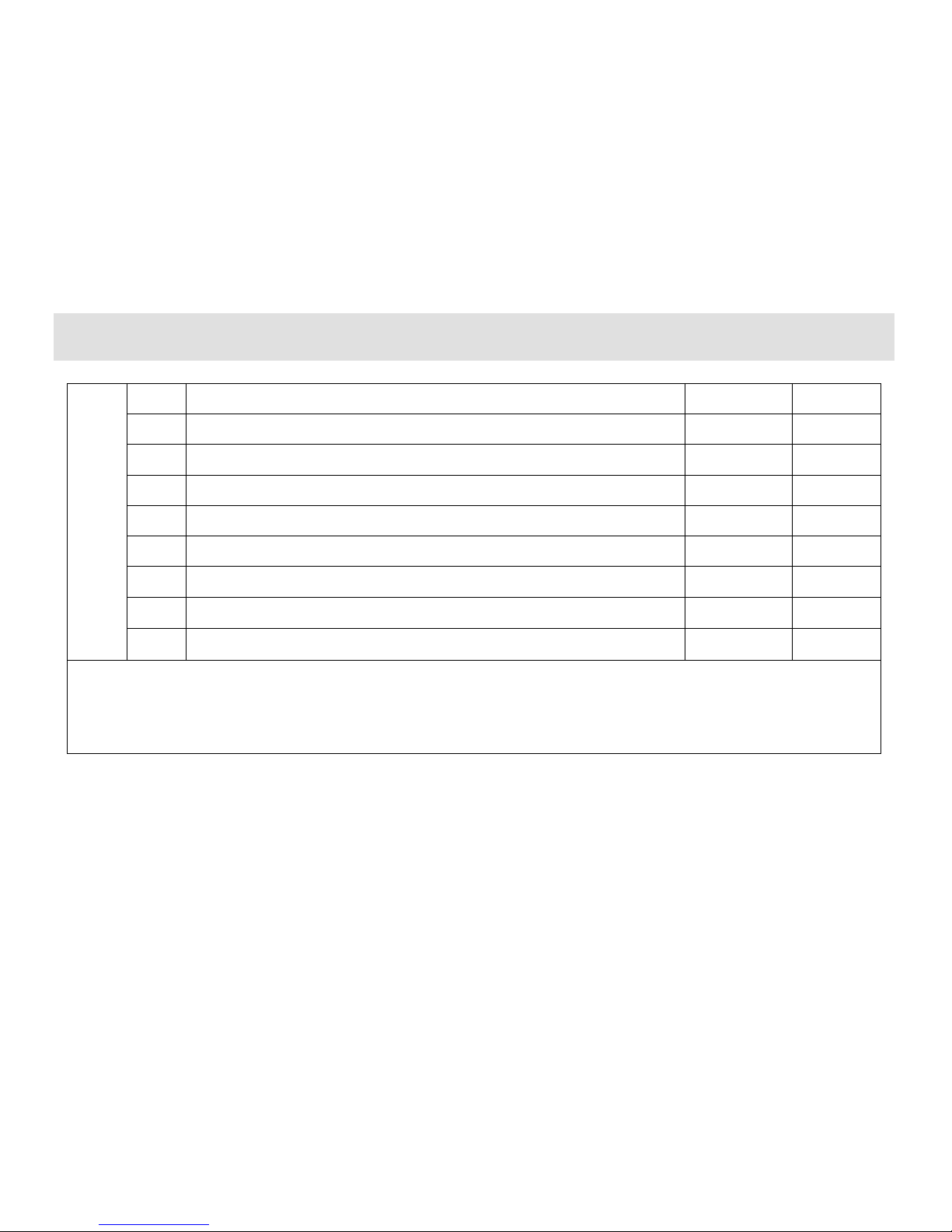
Vehicle Sales and Devlivery Card of CHERY
Category
S/N
Item
Whether inspected and
clarified or not
Performance of Complete Vehicle
1
Engine
Yes □
No □
2
Engine oil, brake fluid, steering fluid, coolant, electrolyte, windshield washer fluid
Yes □
No □
3
Identifications such as VIN number, engine number, nameplate, etc.
Yes □
No □
4
Locks and keys of the complete vehicle
Yes □
No □
5
Lighting system of the entire vehicle includes headlamp, directional signals, fog lamp,
combination light, interior light, stop lamp, reverse light, taillight, reading light, door lamp
and instrument light.
Yes □
No □
6
Windshield glass and body finish
Yes □
No □
7
Speedometer, tachometer, and odometer.
Yes □
No □
8
Wheel house, spare tyre in luggage boot, tool box and service manual for complete vehicle.
Yes □
No □
9
Seat belt, seat, cigarette lighter, A/C switch and duct, glove box and sun visor.
Yes □
No □
10
Window regulator, rearview mirror, wiper, washer, horn/speaker, radio (CD) and antenna
Yes □
No □
Page 14

Brief Introduction
14
o
f
A
p
p
li
c
at
i
o
n
1
93# gasoline for fuel
Yes □
Page 15
Brief Introduction
15
2
Proper use in running-in period
Yes □
No □
3
Operation of complete set of vehicle lights
Yes □
No □
4
Meanings of warning light.
Yes □
No □
5
Proper maintenance time and mileage
Yes □
No □
6
Items of vehicle maintenance in winter/summer
Yes □
No □
7
Proper understanding on cooling system and use of coolant
Yes □
No □
8
Proper operation of air conditioner
Yes □
No □
9
Precautions while starting the vehicle
Yes □
No □
Proper operation of audio devices
Yes □
No □
Signature of seller: Date: Signature of owner: Date:
Page 16

Brief Introduction
16
“One-to-One” Consulting Service Card
Owner’s name: Date of Purchase:
Dealer of Sale Service: Model:
VIN No.
The following items shall be confirmed by the owner.
I. Confirmation of matters of concern when delivery (―√‖ for yes
and ―×‖ for no)
□ Basic methods of application has been introduced, vehicle has
been inspected face to face when delivery
□ Warranty service regulation has been clarified
□ Notices of driving have been clarified
□The significance of regular maintenance as well as maintenance
time/ mileage intervals has been clarified
□The significance of accepting maintenance /service in Chery
Authorized Service Station has been acknowledged.
□ "Maintenance Manual" and "Instruction Manual" have been
delivered, and reminded the owner to read carefully
□ Usage and function of Chery Company's customer service hot
line have been acknowledged
II. Introduction of ―one-to-one‖ consulting service mode ("√" for
yes and"×" for no)
□Always contact your service consultant if the owner has any
problem or requirement, while not someone else
□The service consultant is the only person who is designated by
the service station to communicate with the owner
□ "one-to-one ": only one service consultant shoulders the
responsibility of one owner
□ If not satisfied, owner can select another service consultant
III. Introduction of service consultant's main work ( "√" for yes
and "×" for no)
□ Service and reception of repair and maintenance requirement □
Accept complaints
□ Regular maintenance reminding and return visit □Consulting and
solutions for repair/maintenance
□Regular greeting return visit □Repair/maintenance
reservation accepting
□ Service activities reminding and return visit □ Annual review
reminding/accepting
□Significant festivals greeting □Miscellaneous items handling of
owner's requirement
IV. Establishment of ―one-to-one" consulting service relation
Business card of service
consultant
Signature of owner / date: Signature of service consultant/ date:
First sheet Reserved by Service Station
Page 17

Brief Introduction
17
Page 18

Brief Introduction
18
“One-to-One” Consulting Service Card
Owner’s name: Date of Purchase:
Dealer of Sale Service: Model:
VIN No.
The following items shall be confirmed by the owner.
I. Confirmation of matters of concern when delivery (―√‖ for yes
and ―×‖ for no)
□ Basic methods of application has been introduced, vehicle has
been inspected face to face when delivery
□ Warranty service regulation has been clarified
□ Notices of driving have been clarified
□The significance of regular maintenance as well as maintenance
time/ mileage intervals has been clarified
□The significance of accepting maintenance /service in Chery
Authorized Service Station has been acknowledged.
□ "Maintenance Manual" and "Instruction Manual" have been
delivered, and reminded the owner to read carefully
□ Usage and function of Chery Company's customer service hot
line have been acknowledged
II. Introduction of ―one-to-one‖ consulting service mode ("√" for
yes and"×" for no)
□Always contact your service consultant if the owner has any
problem or requirement, while not someone else
□The service consultant is the only person who is designated by
the service station to communicate with the owner
□ "one-to-one ": only one service consultant shoulders the
responsibility of one owner
□ If not satisfied, owner can select another service consultant
III. Introduction of service consultant's main work ( "√" for yes
and "×" for no)
□ Service and reception of repair and maintenance requirement □
Accept complaints
□ Regular maintenance reminding and return visit □Consulting and
solutions for repair/maintenance
□Regular greeting return visit □Repair/maintenance
reservation accepting
□ Service activities reminding and return visit □ Annual review
reminding/accepting
□Significant festivals greeting □Miscellaneous items handling of
owner's requirement
IV. Establishment of ―one-to-one" consulting service relation
Business card of service
consultant
Signature of owner / date: Signature of service consultant/ date:
Second sheet Reserved by
Page 19
Operation & Adjustment of Interior Devices
19
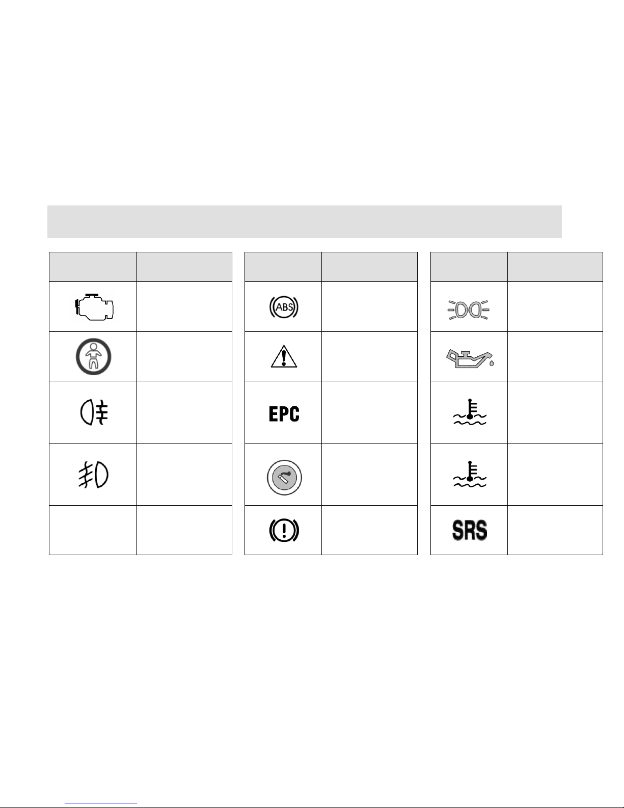
Description of Common Symbols on Vehicle
Symbol
Definition
Symbol
Definition
Symbol
Definition
CHECK ENGINE
Antilock braking
system
Position light
Glass Drive Switch
Prohibitted
Safety warning
Engine oil pressure
warning light
Rear Fog Lamp
Throttle fault
indicator lamp
Coolant temperature
overhigh warning
light (red)
Front Fog Lamp
Cigarette Lighter
Coolant temperature
normal indicator
(green)
A/C
Air Conditioning
System
Brake system
warning light
Identification of air
bag
Page 20
Operation & Adjustment of Interior Devices
20
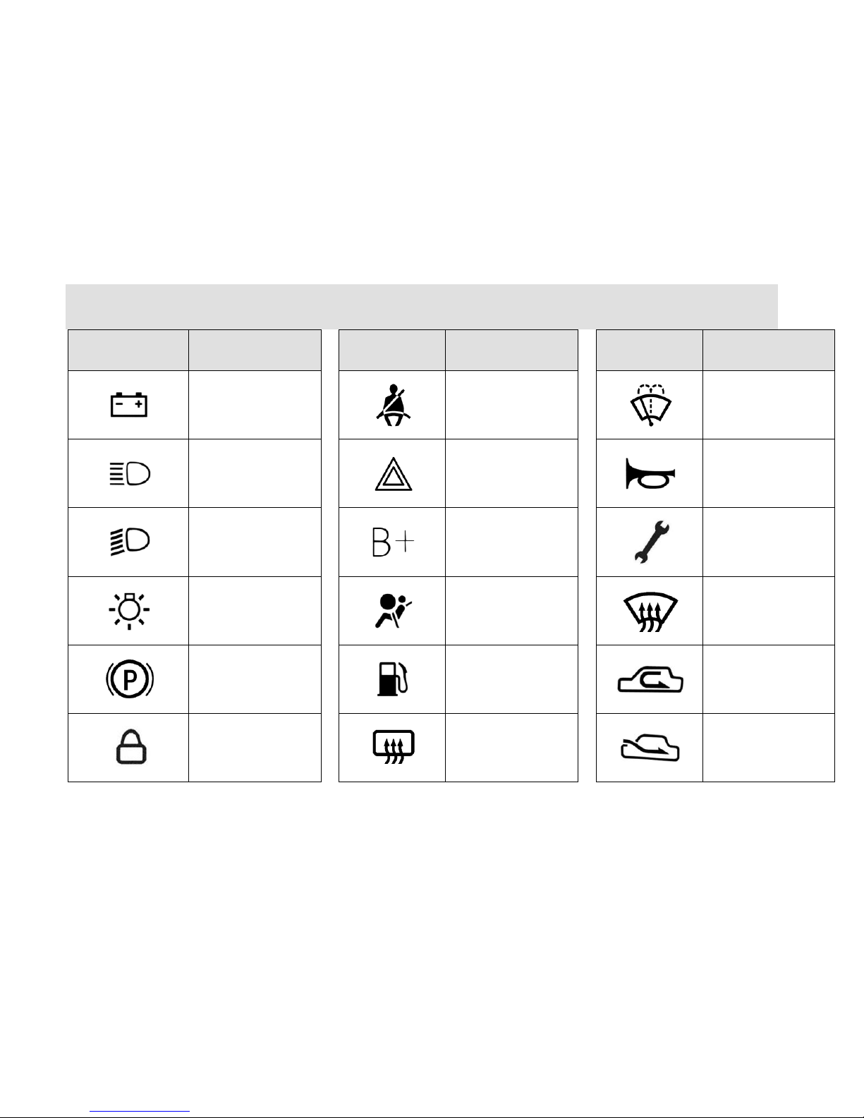
Symbol
Definition
Symbol
Definition
Symbol
Definition
Battery
Seat belt ready
Windshield washing
High beam
Hazard warning
flasher
Horn
Low beam
Battery positive
Vehicle maintenance
indicator
Headlamp switch
Air bag fault
indicator light
Windshield
defrosting/defogging
Parking brake
indicator light
Fuel level low
Inner circulating air
Lockup indicator
Rear windshield
heating indicator
Outer circulating air
Page 21
Operation & Adjustment of Interior Devices
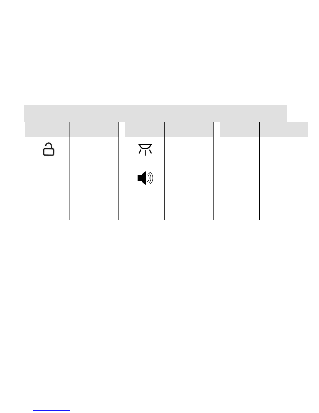
21
Symbol
Definition
Symbol
Definition
Symbol
Definition
Unlock indicator
Indicator for interior
lamp switch
Warning light for
door and trunk lid
open
Audible alarm
Right turn signal
lamp indicator
Left turn signal
lamp indicator
Page 22

Operation & Adjustment of Interior Devices
22
Chapter 2 Operation & Adjustment of Interior Devices
Page 23
23
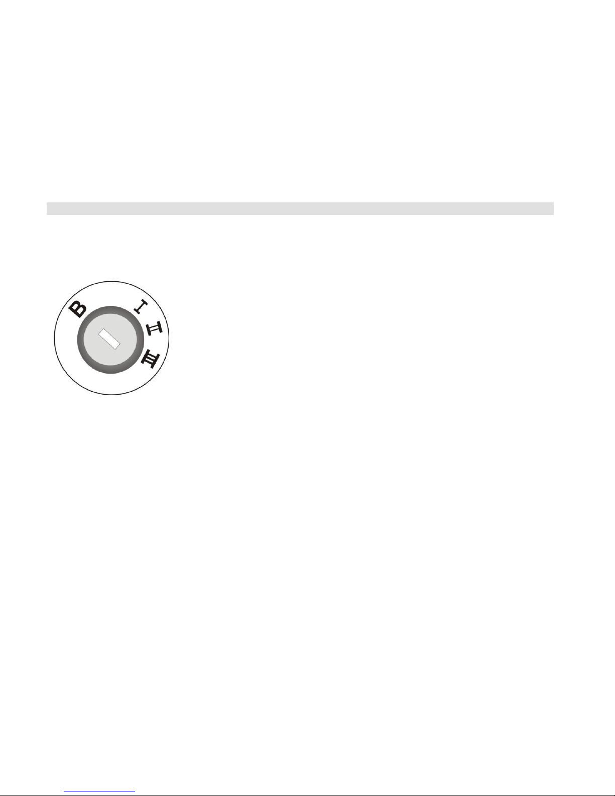
Steering Wheel Lock &
Ignition Switch
The built-up type steering wheel
lock/ignition switch includes the
following key positions:
B--the ignition switch is turned off, and
the steering wheel is locked.
When the key is drawn out from the
ignition switch, the steering wheel lock
will be activated to lock up the steering
wheel.
To lock the steering wheel, after
removing the lock, the steering wheel
shall be turned slightly until you hear
the engage sound of steering wheel
locking.
I -- Steering system unlocked. The
circuits of electrical accessories are
switched on to operate the audio,
cigarette lighter, wiper and other
electric appliances. But the ignition
switch and primary electrical circuits
power off.
If it fails or is difficult to turn the key
from the LOCK position to this
position, you can slightly turn the
steering wheel to the left and right, and
then the steering wheel locking
mechanism will be able to release.
The key of ignition switch shall not be
placed this position for a long time to
avoid using up the power of battery.
II – Switch on the ignition circuit to
enable all electrical circuits to work.
Both warning lamp and indicator light.
This is the proper position of key
during driving, and also is the position
that must be selected when the vehicle
is trailed.
III – To switch on the starting motor,
and start up the engine.
When the locking hole is in this
position, the wiper, audio and other
electrical apparatuses with large
electric power consumption all be
switched off to ensure the vehicle starts
up.
There is a restart proofing equipment
inside the ignition switch. Once the
engine operates, this equipment can
prevent the starter from false startup to
Page 24
24
avoid damaging the engine and the
engine flywheel.
If failing to start, the ignition key must
be turned back to the B position prior
to restart, and then be turned to this
position. After the completion of
startup, release the key and then it will
rebound to the II position.
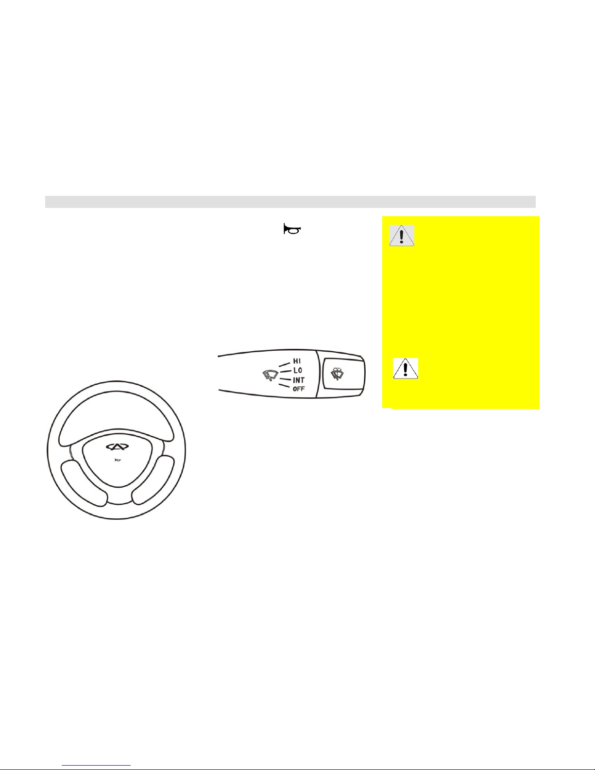
Horn
Press down the button on the
steering wheel to operate the horn. You
also can operate the horn even when
the ignition switch is in the OFF state.
Windshield Wiper &
Washer System
The following functions are available
only when the ignition switch is turned
on. There are four operational positions
in total which shall be in OFF position
in case that the wiper is out of service.
Once the engine starts up,
the key shall be released
immediately. DO NOT stay
on the III position for a long
time.
In the cold seasons, you shall
check whether the wiper
blade is frozen on the
windscreen prior to the use of wiper. If
the blade is frozen on the windscreen,
the wiper can be used only after the
ice-out of blade. Otherwise, it may
damage the motor of wiper.
It also may damage the motor of wiper
if you operate the wiper when there are
some obstructers on the windscreen,
such as snow cover.
Please clear the obstructers before you
operate the wiper.
DO NOT operate the wiper on the dry
windscreen, otherwise it may scratch
the glass and result in the permanent
damage to the wiper blade.
Page 25
25
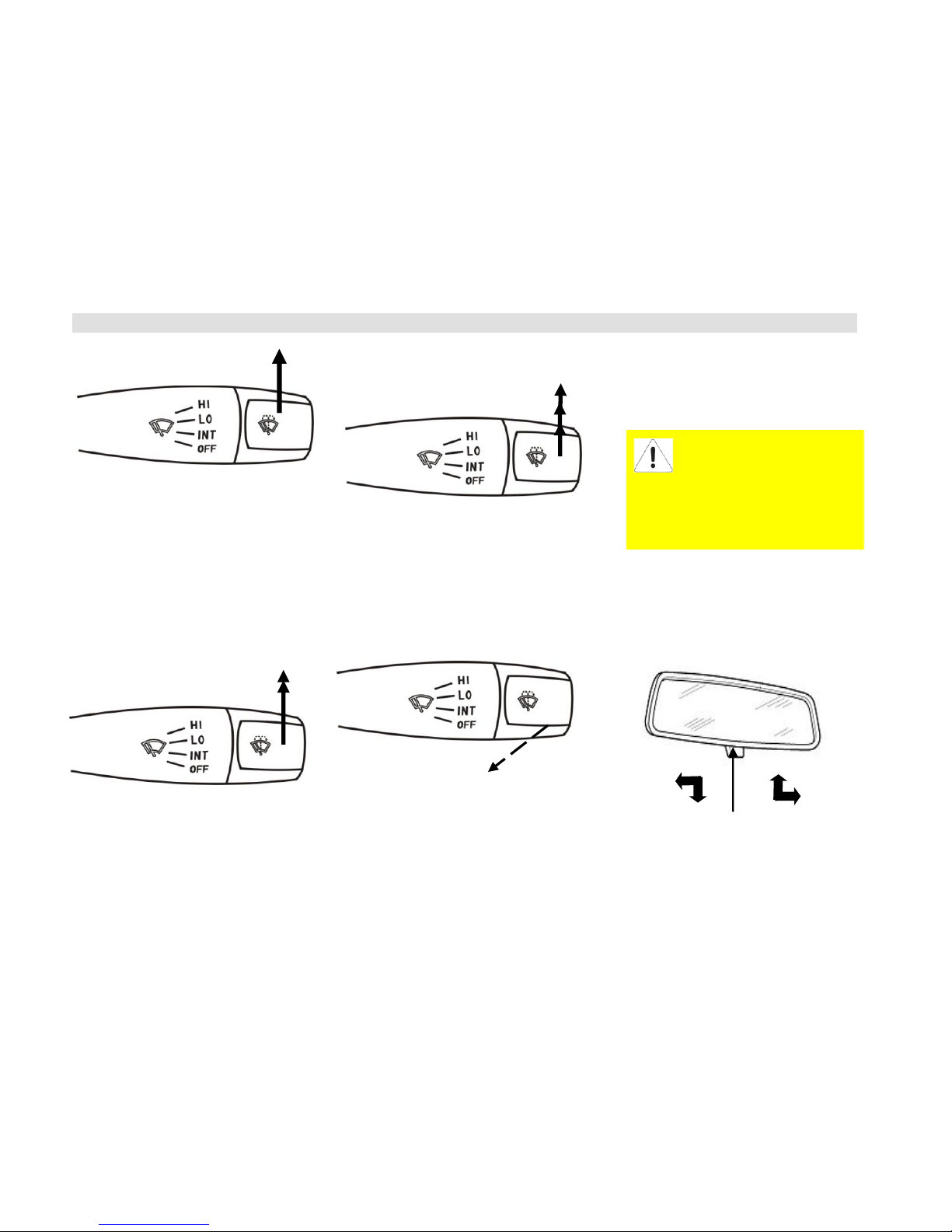
INT (Intermittent Wipe)
Shift the control lever upward to INT
position from OFF position.
The wiper controller will operate
automatically once at every period of
time.
Regular Wipe
Shift the control lever upward past one
position to LO position from OFF
position.
HI (High-Speed Wipe)
Shift the control lever dupward past
two positions to HI position from OFF
position.
Water-Spraying Switch
Pull the switch lever towards the
steering wheel and hold it at this
position, then cleaning liquid will spurt
from the nozzles in front of the
windshield and at the same time the
wipers operate.
Interior Rearview
Mirror
You can turn the doctor bar rightwards
The operation of water-jet
must not be more than 10
seconds, and the operation
cannot be done if cleaning liquid is
not available in the reservoir of
cleaning liquid, otherwise the
water-jet motor may be damaged.
Turn
Left
Turn
Right
Anti-glare doctor bar
Page 26

26
or leftwards to adjust the angle of the
Page 27
Driving
27
rear-view mirror if you want to reduce
the glare when driving at night. When
the doctor bar is turned leftwards, the
rear-view mirror turns downwards a
certain angle; when the bar is turned
rightwards, the mirror turns upwards a
certain angle.
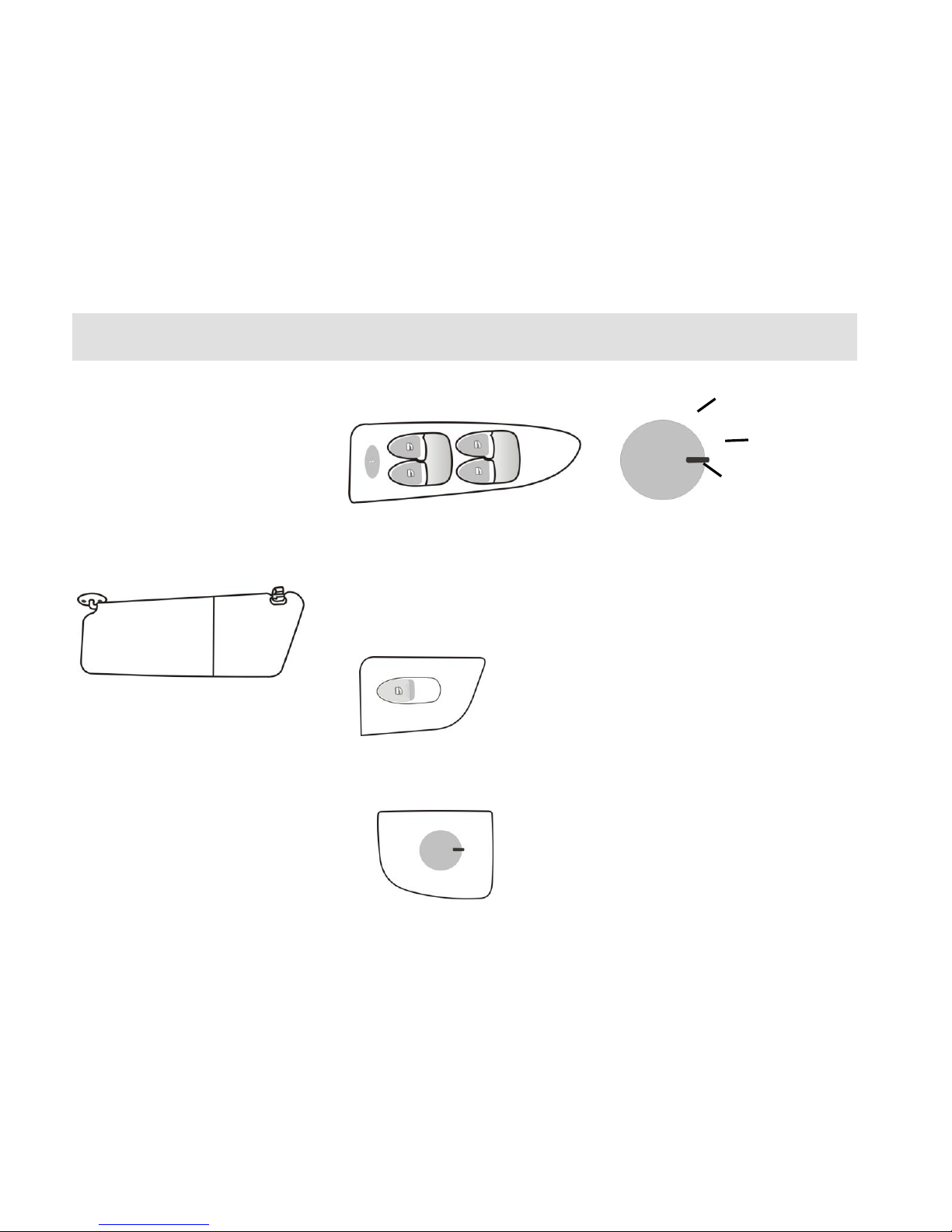
Sun Visor
The sun visor can be unfastened by
loosening the retaining clip and turned
to the side window.
The car running certificate, toll and
invoice etc. can be placed behind the
sun visor.
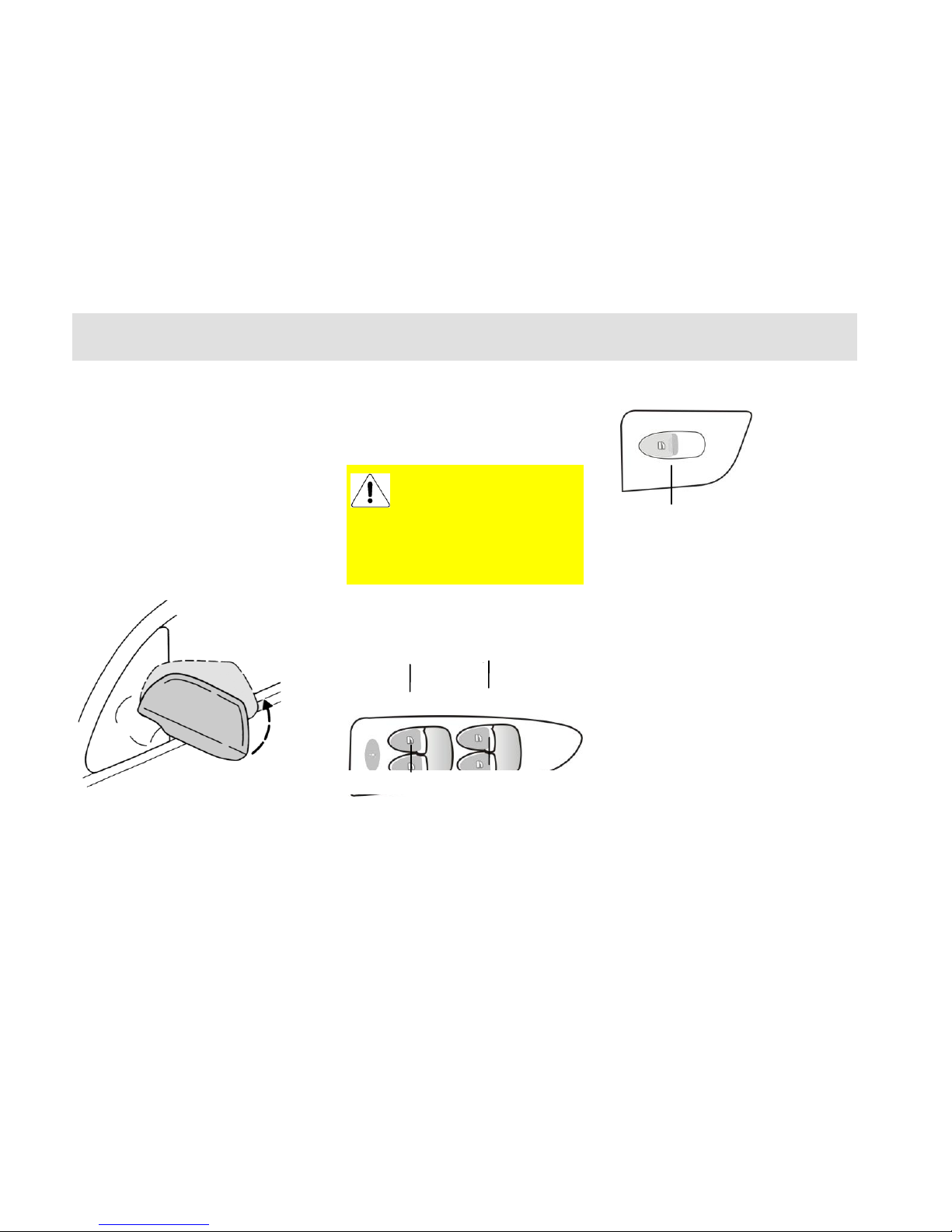
Control Switches on
Doors
The driver-side control switches
are left front, right front, left rear and
right rear electric window switches
and rear window safety switches
respectively.
Electric window switch of rear seat
Electric Exterior Rear-View
Mirror
The electric rear-view mirror can be
adjusted using the regulating switch at
the driver-side The control switch can
operate only when the ignition switch
is in ON position.
When the control switch is turned
counterclockwise to the proper position,
the left outdoor rearview mirror can be
adjusted; when the control switch is
turned clockwise to the proper position,
the right outdoor rearview mirror can
be adjusted.
Left rear-view mirror
adjusting position
Left rear-view mirror
adjusting position
Central
Position
Page 28
Driving
28
When the control switch is turned left
or right to the proper position, push the
switch foreword, backward, leftward
and rightward respectively to adjust the
position of mirror surface upward,
downward, leftward and rightward. The
switch should be turned to the central
position once more after the proper
adjustment.
If necessary, for example the car is in
narrow space, the outdoor rearview
mirror can be folded inside by hand.
The rearview mirror can be resumed to
its original position by unfolding it
outward to the proper position.
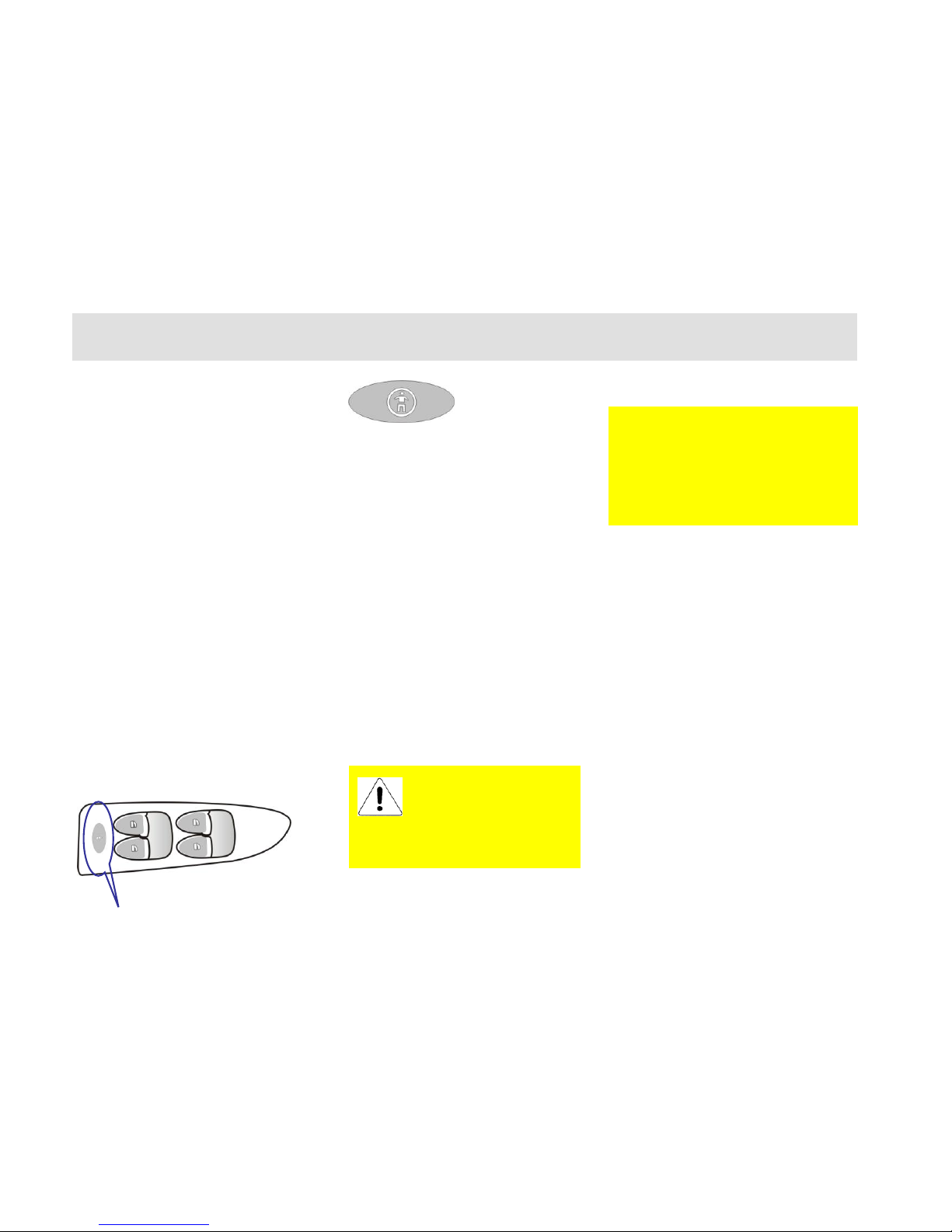
Electric Window
Left front door
Rear Door
The electric window can be operated
only when the ignition switch is at ON
position.
Each window can be operated by its
control switch which fitted on each
door trim panel.
The window can be opened or closed
by press-down or lift its control switch.
During the ascending or descending of
window glass, if the switch is released,
the window glass will stay at the
current position.
The image in the convex
rear-view mirror is
seemingly smaller and
farther than the actual object.
Attention that the actual distance
away from the object shall not be
over-estimated.
Right Rear Window Switch
Right Front Window Switch
Left Rear Window Switch
Left Front Window
Rear Electric Window Switch
Page 29
Driving
29
The window lift control switch has
delay function, that is, it can still
operate within 60 seconds after pulling
out the key.
Each window lift control switch has the
function of light touch, that is to say,
the window glass can automatically
lower to the bottom if the switch is
pressed for one second.
The control switches of other three
windows are available on the door trim
panel at the driver’s side besides the
control switch of the window at the
driver’s side.
Rear Window Safety
Switch
There is a safety switch button on the
door trim panel at the side door. If
press down the button, the switches of
the electric windows on the right front
door and two back doors are controlled.
In this case, the corresponding rear
window switches can be controlled
only through the driver-side rear
window switch. It is recommended to
do so when there is a person with
qualified civil capacity or no civil
disposition capacity children in the rear
seat.
NOTICE:
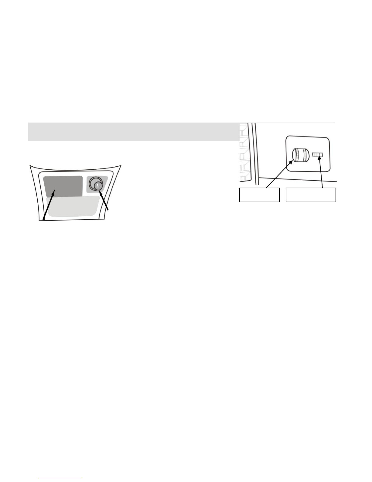
Front Ashtray,
Cigarette Lighter
The front ashtray is located at the front
of the shift lever. Pull outwards the
ashtray by hand and then use it. To
empty the ashtray, draw out the insert
first
The cigarette lighter is located at the
right side of ashtray. Press the cigar
lighter inwards and wait until it
automatically rebound, then the cigar
lighter can be used. Even if the ignition
The cigar lighter cannot
be inserted for a long
time to prevent danger
from happening. If a baby solely
stays in the car, the cigar lighter
should be taken away.
Take car to close the windows! It is to
be noted that you shall observe the
surroundings to avoid the occurrence of
injury accident generated due to
squeeze!
Page 30
Driving
30
switch is off, the cigar lighter can also
be used.
Lighting
Control
While operating the following lighting
equipment, please abide by relevant
traffic regulations.
Headlamp Switch
OFF – Turn off the exterior lamps.
Side Light:
Turn the headlamp switch on the
instrumental panel to the 1st position (i.e.
width lamp position), and, in this case,
front/rear postion lamp and the license plate
lamp light at the same time.
Backlight adjustment:
After the width lamp turns on, the
nightlighting of instrument, audio, A/C,
switch and etc light; and the brightness
of interior backlight can be adjusted by
Headlamp Switch
Backlight Regulating
Switch
Cigar
Lighter
Front Ashtray
Page 31

Driving
31
operating the backlight regualting
switch.
Low beam:
Turn the headlamp switch on the
instrumental panel to the 2nd position (i.e.
low beam position), and then the low beam
lights.
Headlamp High\low
Beam Conversion
When the headlamp swithc is in the
low beam position, i.e., in case that the
low beam turns on, pull downwards the
handle, and pass through the force
point and then convert into the high
beam. The high beam indicator lamp
in the dashboard is also light on
together with the headlamp high beam.
Move the handle towards the steering
wheel to its original position to return
low beam lamp.
Flashing OF Headlamp
During driving, if it is necessary to
flash the headlamp, just move the
handle towards the steering wheel to
the resistant point, and then release the
handle to make it auto return. Repeat
this operation to flash the headlamp
continuously.
Front/Rear Fog Lamp
Switch
The front and rear fog lamps switch is
located on the control handle at the
lower left side of steering wheel.
When the headlamp switch is in the 1st
or 2nd position, turn the handle (section
with a black round point as shown in
the figure), turn on the front fog lamp,
and then turn the handle to turn on the
rear fog lamp.
Page 32

Driving
32
Remind that the headlamp switch shall
be turned on (at 1st or 2nd position) first
in order to turn on the fog lamp. Turn
on the front fog lamp, and then turn on
the rear fog lamp.
When the front fog light is connected,
its indicator lamp in the
instrument light will light on.
Only when it is in foggy, snowy and
rainy weather that badly limit the
visibility can the front fog light be
used.
When the rear fog light is light on, its
indicator lamp in the instrument
light will light.
It is allowed to use rear fog light under
the condition of much lower visibility
due to its strong dazzle function.
Turning Signal Lamp
Only with the ignition switch on can
the turn signal light works.
Left turn signal light --- Move the
handle downwards.
Right turn signal light --- Move the
handle upwards.
When the turn signal light is connected,
its turn signal indicator light in the
dashboard will flash together with.
Interior front ceiling lamp
Switch is in the right position: ceiling
lamp extinguishes.
Switch is in the left position: ceiling
normally lights.
Switch in in the central position:
ceiling lamp lights when any door
opens while extinguishes when the
door closes.
Trunk Lamp
If the trunk opened, the light will turn
Page 33

Driving
33
on (but it is not under the control of the
ignition switch). After parking, please
notice to cover the trunk properly.
Hazard Warning
Flasher Switch
The triangle shape as shown in the
figure is the hazard warning flasher
switch. This switch is located on the
central instrument console, and the
position between the audio panel and
A/C control panel.
The hazard warning flasher switch is
applied only in case of a emergency to
give an alarm to the vehicles which
follow your vehicle and tell them that
your vehicle has trouble or hazard. The
system can by turn on/off immediately
press-down the switch. With the
ignition switch at OFF position, this
hazard flasher warning lamp can also
be operated.
After the warning flasher turns on, the
indicator light (yellow area) on the
switch flashes. The right and left turn
signal lights on the combination
instrument also flash at the same time.
Braking Lamp
Step down the brake pedal to light on
braking lamp; if release it, the lamp
will turn off immediately.
Backup Lamp
After turning on the ignition switch and
shifting to the Backup position, the
backup lamp lights while extinguishes
after turning off the ignition switch or
shifting to other gear positions.
前排烟灰缸
Page 34

Driving
34
Chapter 3 Driving
Page 35

Driving
35
DRIVING
Start-up
Preparatory work before
start-up
The start-up of engine is controlled by
the electric control system of the
engine.
To start up the electronic injection
engine, do not step on the gas pedal
before and during starting. You step on
the gas pedal only when it is a poor
start. For the details about the start of a
vehicle, see the Section ―Start-up of
engine‖ of this chapter.
Safety considerations
The idling speed of an engine is
controlled by the electric control
system. The idling speed is high when
the engine starts, which is
advantageous to increase the
temperature of the engine. After the
temperature of the engine rise, the
idling speed shall decrease
automatically. If the idling speed fails
to decrease automatically, you shall get
to the Chery Authorized Service
Station to make your vehicle repaired.
Do not make the engine operate at the
speed, which is more than the specific
idling speed, for above 10 minutes.
Before the vehicle starts:
1. Confirm that all passengers fasten
their safety belt. For the safety
belt and its instruction, see the
Chapter ―Seat and Safety
Protection‖
2. Confirm that the front headlamp
and other electrical accessories
power off.
3. Confirm that the handbrake is
pulled up.
4. Confirm that the selector lever is
in NEUTRAL position.
The long-time high-speed idling
of an engine may create
over-high temperature of the
engine and exhaust system, which has
the risk of firing and other damages.
Therefore, DO NOT make your vehicle
stop, travel at idle speed or run on the
ground where there are hay or other dry
coverings. The exhaust system may
make the temperature of the engine
compartment and exhaust pipe rise up,
which it may cause a fire.
DO NOT start up your vehicle
on the airproof garage or other
enclosed locations. The exhaust
gas from a vehicle is noxious. The door
of garage must be opened before the
engine starts. For the details, see the
section ―Caution against the exhaust
fume from a vehicle‖ in this chapter.
Page 36

Driving
36
5. Turn the ignition switch to the
―Ⅱ‖ position other than the (III).
If it needs great effort to turn the key,
you can turn the steering wheel
leftwards and rightwards until the key
can be turned freely. This may be
conducted by the following several
reasons:
The front wheel deflects.
The front wheel touches the curb.
The steering wheel is turned when
you go abroad or get down. (The
steering wheel self-locks).
6. Turn on the ignition key, and, at
the same time, confirm that the
instrument panel warning lamp
lights for a short time. If the lamp
doesn’t light, it is required to get
to the Chery Authorized Service
Station to make your vehicle
required.
Start the engine
1. Turn the ignition switch to the
―Ⅲ‖ position, DO NOT step on
the accelerator pedal, and release
the key immediately after the
engine starts. In this case, the key
returns back to the ―II‖ position.
2. If the temperature is more than
-12C and it is difficult to start
the engine within 5 seconds for
the first start, then you shall turn
the key to the OFF position and
wait for 10 seconds to have a
retry.
3. If the temperature is less than
-12C and it is difficult to start
the engine within 5 seconds for
the first start, then you shall turn
the key to the OFF position and
wait for 10 seconds to have a
retry. If the engine fails to start
twice continuously, you can step
on the gas pedal to the extreme
and keep this position, and then
turn the key to the START
position. After the engine starts,
release the key, and then release
the accelerator pedal slowly as
the engine speed increases.
4. After the engine starts, it operates
for several seconds at the idling
speed, and then you step on the
foot brake, release the handbrake
and shift to a drive gear to
If the driver’s safety belt is already
fastened tightly before the ignition key
turns on, the safety belt warning lamp
doesn’t light.
Page 37

Driving
37
prepare for driving.
5. The ambient temperature range
applicable to normally start an
engine is -25℃ - 40℃ (when the
ambient temperature is out of this
range, other abnormal conditions
may appear).
Beware of the car’s
exhaust fume
Though the car’s exhaust fume is
colorless and odorless, it contains
carbon monoxide, the poison of which
you must beware of. Some integrants in
the engine’s exhaust gas and chemicals
contained in or emitted by some
automotive parts may be carcinogenic,
cause neonate defects or other genital
system impairments.
In the following cases, check the
exhaust system and the body
ventilation system of the car.
Lifts the car for overhaul.
The sounds of the exhaust system
change.
The car is damaged by collision.
Remember to ventilate
Open the car’s windows for more than
2.5cm when parking and idling the car
long in an open area, or, turn on
ventilation function of A/C system to
enable fresh air to enter the car.
In case foreign smell of exhaust fume
is smelt inside the car,
immediately request a
Chery Authorized Service
Station to overhaul the car and do not
continue to drive. The exhaust fume is
noxious and may endanger life.
Clear snow, fallen leaves
and other foreign
material blocking at the
air inlet to improve the ventilation
capacity of the car.
Air vent
Page 38

Driving
38
Self-adapting function
of the engine’s control
system
If the battery cable has been ever
removed, some abnormal phenomena
may occur in the initial running stage
of the car after reconnection. This is
because the engine’s control system is
re-studying to adapt the engine, which
are normal phenomena.
Revolution limitation to
the engine
To protect the engine, engine
revolution is limited by an electronic
unit-ECU.
Shut down the engine
Release the accelerator pedal, wait until
the engine revolution falls to idle speed,
and then turn off the ignition switch.
Do not shut down the engine
immediately when parking after a long
time high speed running; leave the
engine continue to run for 2 minutes at
a revolution higher than the idle speed,
so that the engine temperature can fall
gradually.
Note:
Brake
Do not apply the
accelerator pedal before
shutting down the engine.
The engine temperature will remain
high after the ignition switch is turned
off and the engine stops, so, leave the
electronic cooling fan of the radiator
continue to run for about 10 minutes.
Even if the cooling fan stops running, it
may run again suddenly because of
high temperature. Therefore, take
special care when working by the
engine.
Page 39

Driving
39
Dual-circuit brake system
You car is equipped with a diagonal
dual-circuit brake system. In case one
of the two circuits fails, the other
circuit still can maintain effective
operation.
Brake fluid
If the brake system alarm lamp does
not extinguish when releasing the hand
brake, it indicates that the brake fluid
level is too low.
Check the brake fluid level height
regularly as required.
Working instructions for
the brake system
It is normal for the brake system to
make some noises occasionally.
However, in case it makes sounds like
grinding between metals or screams,
the brake linings may be seriously
worn and need to be replaced. Then,
send the car to a Chery Authorized
Service Station for overhaul.
Send the car to a Chery Authorized
Service Station for overhaul, in case
there is a steady chatter or vibration
being transferred to the steering wheel
when braking.
The new brake lining must go through
a running-in before reaching its optimal
braking effect. The braking effect will
fall a little in the initial 200 kilometers,
under which case, apply a larger force
to the brake pedal properly to
compensate the braking effect. This gist
also applies to the new brake lining
replaced.
The wear status of the brake lining
depends greatly on the operating mode
and driving method. For a vehicle
mainly used in urban traffic, the
working conditions of its brake linings
is very hard, therefore, be sure to send
the car to a Chery Authorized Service
Station for inspection of the thickness
of the brake linings or for replacement
of the linings at the specified
In case one of the two brake
circuits fails, you need to
apply a larger force to the
brake pedal and the stopping distance
will also be longer. In such case,
send your car to a Chery Authorized
Service Station for overhaul before
proceeding to your journey.
Immediately add brake
fluid to maintain the liquid
level at MAX mark and
send the car to a Chery Authorized
Service Station for inspection of the
brake system.
Page 40

Driving
40
maintenance mileage.
When running downhill, shift to a
lower gear timely to make full use of
the engine’s brake action so as to
reduce the load of the brake system.
At this time, do not keep stepping on
the brake pedal even if braking is
needed.
The damp brake disc may reduce the
brake efficiency. After paddling,
rainstorm or car washing, apply the
brake pedal lightly to make the brake
disc and brake lining rub to generate
heat, which will evaporate the water
and recover the braking effect.
Brake booster:
The brake booster is
controlled by the engine vacuum.
This device will operate only when
the engine works, so, never slide
when the engine is engine flameout
during downhill running.
In case the brake booster is unable to
work because of the car’s being towed
or sole failure, apply a larger force on
the pedal to compensate the booster’s
effect.
Therefore, it is desirable that no foot
pad or other coverings are laid on the
floor around the pedal. If really
required, ensure that the foot pad laid
will neither hamper the movement of
the pedal nor slide itself.
ABS Antilock brake system
(ABS)( )
ABS can avoid lock of wheel. It
can even enable the car maintain
steering behavior during emergency
brake, which allows you to avoid the
barriers.
If the front spoiler is added on
the car, ensure that the airflow to the
front brake is unblocked; otherwise, the
brake system may overheat due to poor
heat emission, thus reducing braking
effect.
Each pedal could be stepped
to extreme and can return completely
and move freely.
Page 41

Driving
41
Actions of ABS
ABS does not work during the normal
braking; it works only when the wheel
is to be locked. When braking, the
brake pedal’s fluctuation accompanied
by noises indicates that ABS is working;
such fluctuation and noises are normal.
At this time, do not release the brake
pedal.
Use ABS to brake
Keep applying the brake pedal with full
force during an emergence may initiate
ABS immediately, which enables you
to keep control over steering and avoid
the barriers where enough space is
available.
We recommend you firstly get familiar
with this brake technique, however,
avoid taking any unnecessary risk.
Self-inspection of ABS
ABS will perform self-inspection after
the car starts. Some mechanical noises
can be heard during this course, which
is normal.
Though ABS can ensure
the optimal braking effect,
the stopping distances
may vary greatly with road surface
status. ABS can not always ensure
reduction of stopping distance. For
example, on sands or snow, the
stopping distance of a car with ABS
may be longer than that of a car
without ABS. Also, you can not use
ABS to eliminate the dangers
caused by extreme close to a car
before, paddling, sharp turning or
bad road surfaces as well as to
prevent the accidents due to mistake
and incorrect driving. Please drive
with care and slow down when
turning.
In case the ABS alarm lamp
is found light during
running, it indicates that a
failure occurs in ABS system; then,
stop the car and contact a Chery
Authorized Service Station.
Page 42

Driving
42
Hand brake
After parking, tighten the hand brake
upwards to prevent the car from sliding
due to lapse of attention.
When applying hand brake with the
ignition switch turned on, the brake
alarm lamp will light.
Pull up the hand lever to use the hand
brake.
To release the hand brake, pull up the
hand lever slightly, press down the
release button at the end of the handle
and simply push it down.
The hand brake applies action on the
rear wheel. Applying the brake pedal
while pulling up the hand brake can
facilitate the hand brake’s pulling up.
Gearshift
Methods and attentions for
use/operation:
When shifting gear, completely
apply the clutch pedal and rapidly
control the gearshift lever to shift
gear after the driver has detached
Pull up the hand brake
handle before leaving the
car.
Use the important
principle of ABS
brake
1. Apply the brake
pedal with full force
and then hold
2. Turn the steering wheel to
round the barrier. No matter how
fierce the braking is, you can
maintain control performance
when turning.
Page 43

Driving
43
the engine torque.
Apply a slow speed gear when
running downhill and turning;
sliding with the clutch
disengaged is not allowable.
When shifting the transmission
from a lower gear to a higher gear,
do not step over gear; otherwise,
the synchronizer’s service life
may be affected.
Utilizing the synchronizer to
forcibly shift gear to start the
engine under NEUTRAL and
flameout state is forbidden;
otherwise, the synchronizer’s
service life may be affected.
When shifting gear, the flapping
method (i.e. one push and one
release) is forbidden and you
should keep pressing the gearshift
lever, thus greatly reducing
sliding and rubbing time of the
synchronizer’s lock ring and
reducing friction.
Do not put your hand on the
gearshift lever when driving;
otherwise, it will cause excessive
wear of the shift fork.
Immediately stop the car to
inspect when abnormal sound in
transmission is heard and such
abnormal phenomena as obvious
resistance during operation etc.
are found. Continue to drive only
after the failure is removed.
Steering
In order to avoid damage to the power
steering system:
When the engine is running, do
not turn the steering wheel to its
extreme position (turn to its left
or right dead point) for more than
10 seconds.
Refill power steering fluid at once
when its liquid level is blow MIN
mark in its reservoir. Do not drive
the car before refilling.
In case of failure in the power steering
system or engine shutting down, the car
will lose the steering booster force.
Then, you still can turn the steering
wheel, but a larger force is required.
Check the following items if the car
wanders or swings:
If any tire is under-inflation
Page 44

Driving
44
If the wear status of the tires is
even
If any suspension component is
loose or worn
If any steering component is loose
or worn
If wheel alignment is correct
Wading
If the car has to wade during journey,
be sure to drive carefully and slowly,
especially when you do not learn the
water situation. Do not continue to
drive ahead if the water can submerge
the wheel hubs.
When paddling, both traction and brake
performance of the car will fall and the
car also may be in danger of flameout.
If water enters the intake pipe of the
engine, it will cause serious damage to
the engine. In case of a deeply paddling,
the water can enter into the
transmission from the air vent, which
may damage the transmission.
After paddling, be sure to drive slowly
and slightly apply the brake pedal for
several times to remove the water from
the brake. The water on the brake will
make brake performance fall.
3-way catalytic
converter
The catalytic converter helps to reduce
the exhaust gas pollution.
The gasoline engine car is equipped
with narrow-necked filler, which can
only accommodate the compressor gun
Be sure to use the unleaded
fuel. The leady fuel can cause
permanent damage to the
catalytic converter and the oxygen
sensor. Chery Automobile Corporation
Limited will not be responsible for any
damage due to use of leady fuel. The
damages of this kind are beyond the
scope of maintenance guarantee.
Please contact the nearest Chery
Authorized Service Station
immediately if you have added the
leady fuel by accident.
Unleaded gasoline
Page 45

Driving
45
for unleaded gasoline.
Drive a car equipped with
the catalytic converter
Avoid any case that may cause
unburned or partly unburned fuel to
enter the catalyst, especially when the
engine is at a high temperature.
Avoid the following cases:
Fuel is exhausted.
Unnecessary and long starting of
the engine.
Let the engine run with one of the
spark-plug cable joints removed.
Start the car whose engine is still
at the working temperature by
pushing or towing.
Turn off the ignition switch
during running.
Parking
Do not park, idle or drive the car on dry
leaves or hay. Potential fire hazard still
exists even if the engine is flameout,
because the exhaust gas will still emit
considerable heat in a short time.
Be sure to turn off the ignition switch
before leaving the car. Do not leave the
engine run with nobody inside the car.
If you neglect this point, your car may
move by chance, which may cause
It is absolutely unallowable to
pull out the ignition cable of
the ignition coil to check if the
working status of the engine is normal
or to observe the spark jump status of
the spark plug by means of cylinder
flameout; otherwise, the 3-way
catalytic converter may be damaged.
During driving, drive the
car at a lower speed to the
nearest Chery Authorized
Service Station in case of poor
ignition or performance fall of the car.
Be sure not to drive at a high speed.
Note:
If the engine is working all
the times, the 3-way catalytic
converter will become very
hot. Therefore, remember to
wear protective glove during
maintenance to avoid scald.
Page 46

Driving
46
personnel injury or property damage.
Chassis protection
You car is equipped with heat shield.
Do not apply any painting dressing on
the body of the heat shield, exhaust
pipe or catalytic converter or its
vicinity area. Do not remove the heat
shield.
Fuel consumption
Fuel consumption is
affected by the following
factors:
Driving speed and gear
selection
Stroke distance/engine
temperature
Frequent cold start and short distance
driving may obviously make the fuel
consumption rise.
Traffic and road status
Traffic jam, uphill, excessive curves
and rough road surface will all have
adverse influences on the fuel
consumption.
Good driving habit
Foreseeing the dangerous condition and
keeping a safe running distance with
the vehicle before can reduce not only
the fuel consumption but also wear and
noise of the brake.
Load condition of the car
Increasing the load of the car may
cause higher fuel consumption.
Technical condition of the car
Under pressure of the tire or improper
maintenance for the engine and the car
will also cause higher fuel
Fuel consumption
Speed
The above chart indicates
how the fuel consumption is affected
by the driving speed and the gear
selection. Maintaining at a lower gear
to improve acceleration performance
may cause obviously higher fuel
consumption.
When the car is in a traffic jam
at a level crossing or waiting for the green
light long, engine flameout is
recommended, because too long idling of
the engine may increase fuel consumption.
Page 47

Driving
47
consumption.
Essentials for fuel-saving
driving and environmental
protection:
Run under fuel-saving mode and
use additional electric load only
when necessary.
Start without pre-warming the car.
Apply the gas pedal smoothly.
Quickly shift to the next higher
gear to obtain a lower engine
revolution.
Foresee the traffic status.
Immediately turn off A/C and rear
windshield heating functions
when unnecessary.
Regularly check/adjust the tire
pressure.
Regularly perform maintenance
for the car, which should be
implemented by a Chery
Authorized Service Station
preferably.
Radiator fan
The radiator fan is an electric one and
its working condition is controlled by
ECU of the engine. The switch will
automatically turn on the fan circuit
when the coolant or the engine
compartment reaches a certain
temperature.
Descriptions:
If the fan fails to run after the
temperature of the coolant reaches the
start-up temperature of the fan, check
the fuse of the fan for blowing out, if
necessary, replace the fuse.
The revolution of the fan has no
relation to that of the engine and
After parking and shutting
down the engine, the
radiator fan will continue to
run for a period of time (about 10
minutes) because the engine is still
under a thermal state and it will stop
running until cooled to a certain
temperature. Even so, the fan still can
start suddenly due to temperature rise
in the engine compartment caused by
the temperature of outside
surroundings (under insolation or in a
high temperature region). Therefore,
be careful when working in the
engine compartment to avoid
occurrence of any accident!
Page 48

Driving
48
shifting to a lower gear can not
increase the cooling effect of the fan.
Therefore, need not to shift to a lower
gear when the engine runs smoothly
and its speed does not fall obviously
when climbing.
Page 49

Instrument Panel
49
Chapter 4 Instrument
Panel
Page 50

Instrument Panel
50
Instrument
Panel
Combination
Instrument
Wiper Switch
Horn Switch
Engine Hood
Pull-up Switch
Steering
Wheel
A/C Vent
A/C Vent
A/C System
Audio System
Exterior
Rear-view
Mirror Knob
Turn Signal &
Position Lamps
Switch
Nightlight
Adjusting
Switch
Glove Box
Wind Direction
Adjusting Knob
Page 51

Instrument Panel
51
Combination Instrument
Panel ( )
1
2
3
4
5
7
20
20
22
16
17
18
19
15
14 9 10
11
12
13
7. Airbag Warning Light
8. Brake System Warning Light
9. Engine Oil Low Warning Light
10. Fuel Low Level Warning Light
11. Coolant Temperature/Level
Warning Light
12. Electronic Throttle Fault
13. Right Turn Signal Lamp
Indicator
14. Maintenance Indicator
15 Front Passenger Side Air Bag
Switch Indicator
16. Parking Position Indicator
17. Front Fog Lamp
18. High Beam Indicator
19. Parking Brake Indicator
20. LCD Display
21. Clock Adjusting Button
22. Rear Fog Lamp
1. Left Turn Signal Lamp Indicator
2. Door Open Warning Light
3. Battery Charging Indicator
4. Seat Belt Warning Light
5. Engine Fault Warning Light
6. ABS Warning Light
Page 52

Instrument Panel
52
Warning devices
The warning devices are used to show
driver the traveling condition of the
vehicle and whether the vehicle has
gotten problems which can cause serious
damage and harm to the vehicle. If some
one system has trouble, its corresponding
warning light will light or flash.
When the ignition switch turns on, a
majority of warning lights will light for a
short time to perform the system
self-checking. If a certain warning light
does not light, or it still lights or flashes
continuously after the engine has started,
please drive your vehicle to the CHERY
Authorized Service Station to make the
related system repaired.
Low fuel indicator lamp
When the level of fuel in the fuel tank is
below 10 liters, this lamp lights and give
an alarm, and the pointer of the fuel
gauge will point to the red alarm line.
When the indicator lamp lights, please
refuel as soon as possible.
ABS Warning light
In case that the ignition switch turns on,
this warning light will light for a short
time and the ABS system will perform
self-checking at the same time and
determine whether the system is in good
condition. If this warning light
continuously light or flash after the
ignition switch turns on or during the
traveling of vehicle, it indicates that this
ABS system has trouble. However, the
vehicle still has the general braking
ability (without ABS) unless the brake
system warning light also lights. In this
case, please drive your vehicle to the
CHERY Authorized Service Station to
make it repaired A.S.A.P. However, you
should drive carefully and don’t drive at
high speed. Please refer to ―Brake‖ for
the precautions on the use of ABS
system.
8
6
Page 53

Instrument Panel
53
Parking brake warning light
This warning light works only after the
ignition switch turns on.
After the hand brake is pulled up, this
warning light will keep lighting.
Brake system warning light
This warning light works only after the
ignition switch turns on. In case that the
brake system fails to operate or the brake
fluid level is low, this warning light will
light.
When this warning light turns on, check
whether the brake fluid level is low. If
the brake fluid level is low, immediately
refill the brake fluid up to the level
between the MIN and MAX marks, and
please get to the CHERY Authorized
Service Station to make this system
inspected.
Parking/Position indicator
lamp
When the position lamp turns on, this
indicator lamp lights.
Seat belt warning lamp
In case that the ignition switch turns on,
the warning lamp will light to remind the
driver to fasten his/her seat belt if he/she
doesn’t fasten the seat belt.
Engine fault warning lamp
If the brake system warning light lights
during driving, it indicates
there is something wrong
with one of dual-brake circuits. In this
case, carefully drive your vehicle to the
nearest CHERY Authorized Service
Station to make this system examined
and repaired by the professionals.
Considering the serious decrease of
braking performance and the extension
of braking distance, you shall keep
longer distance from the previous
vehicle during driving, and shall
increase the pressure applied on pedal
as required.
If both the ABS warning light and the
brake system warning light are ON
simultaneously and persistently, stop
the vehicle immediately under the
condition of safety warranty. Prior to
continuing your journey, please drive
your vehicle to the CHERY Authorized
Service Station to make the brake
system examined.
Page 54

Instrument Panel
54
When the ignition key is ON, this
warning light flashes and the engine’s
electric control system is in the
self-checking state. If there is no trouble
in this system, then the warning light
extinguishes after the engine starts up,
and if the warning light flashes at all
times, the engine must be checked.
If the warning light flashes during
driving, it indicates there is something
wrong with the electric control system of
the engine, please get to the nearest
CHERY Authorized Service Station as
soon as possible to make your car
examined and repaired.
High beam indicator light
When the high beam indicator light lights
or the headlamp flashes, this warning
light will light.
Turn signal indicator light
There are a left turn signal indicator light
and a right turn signal indicator light.
When the left/right turn signal lamp turns
on, the corresponding turn signal
indicator light also flashes slowly at the
same time. When the hazard flasher
warning light is ON, the left/right turn
signal lamp and the left /right turn signal
indicator light will flash at the same time.
If the flashing rate of the turn signal
indicator light is quicken to the twice of
original value, it indicates there is some
wrong with the corresponding turn lamp.
Airbag warning light ( )
When the ignition switch is ON, the fault
indicator shall light for 3 – 4 s and then
extinguish. It indicates that the airbag
system works normally. If the fault
indicator lights continuously, it indicates
there are trouble codes.
If this warning light flashes during
driving, it indicates there are some
troubles in this system. In the case, drive
the vehicle to the CHERY Authorized
Service Station to make this system
examined.
Page 55

Instrument Panel
55
Front passenger side airbag
switch indicator light ( )
There is a front passenger side air bag
switch at the side of front passenger side
instrument panel, with the ON/OFF
position which can be selected by
inserting and turning the ignition switch.
In case that OFF is selected, the indicator
light of PAB (Passenger Airbag) on the
instrument panel lights, and the front
passenger side air bag fails to operate.
And in case that ON is selected, the
indicator light extinguishes.
Low engine oil pressure
indicator lamp
When the ignition switch is ON, this
indicator lamp flashes, and then
extinguishes after the engine starts up. If
this lamp still light persistently after the
engine starts up or if it flashes during
driving, please stop your car immediately,
shut down the engine and check the
engine oil level.
In case that the engine oil pressure is
below 0.3 Bar and the speed of engine is
less than 300 rpm, the indicator lamp
flashes to give an alarm to the driver.
In case that the engine oil pressure is
below 0.3 Bar and the speed of engine is
greater than 300 rpm, the indicator lamp
flashes, and the buzzer gives an alarm at
the same time.
If the engine oil level is considerably low,
immediately refill the engine oil.
Generator warning light
The warning light shall light when the
ignition switch turns on, and extinguish
after the engine starts.
If this warning light does not extinguish
or if it lights during driving, please stop
your vehicle immediately, shut down the
engine, and then check the generator belt.
If the generator belt is in good condition,
please immediately drive your vehicle to
the nearest CHERY Authorized Service
Station to make your vehicle examined
and repaired. But in consideration of the
fact that the battery will discharge
continuously during driving, all the
unnecessary electrical equipment shall be
turned off, including A/C system.
If the generator belt has been damaged,
you should not drive further, and the
If the engine oil is used out
quickly, please get to the
CHERY Authorized Service
Station to make your vehicle
examined.
Page 56

Instrument Panel
56
vehicle must be overhauled by
professionals.
Coolant temperature/level
warning light
After the ignition key is ON, this light
shall light for several seconds, and then
extinguishes. If the lamp still light after
several seconds or if the light flashes due
to the over-high temperature or low level
of the coolant, and the buzzer gives an
alarm at the same time during driving,
stop your car immediately, shut down the
engine and check the coolant level, and
refill the coolant as required.
Door/Trunk lid OEPN
warning light
This warning light is located at the center
of the clock display on the center of
instrument panel. When the ignition
switch turns on, this light will indicate
the condition of four doors and trunk lid
if not properly close.
Electronic throttle fault
warning light
This warning light shall light when the
ignition switch turns on, and the engine’s
electric control system shall
automatically check the electronic
throttle. If this system has no trouble, the
warning light will extinguish after the
completion of self-checking, and if this
warning light flashes at all times, the
eletronic throttle must be checked.
If the warning light flashes during
driving, it indicates there is something
wrong with the engine’s electronic
throttle, please get to the nearest CHERY
Authorized Service Station as soon as
possible to make your car examined and
repaired.
Brake lining warning light
When the brake lining is seriously worn,
this warning light will light to give an
alarm. In this case, please drive your
vehicle carefully and get to the Service
Station to make brake lining replaced
A.S.A.P.
Be care not to be scalded!
If the engine is hot, the
cooling system is in high
temperature, high-pressure state.
Thus, take care to open the radiator
cap only after the engine cools down.
Never touch the radiator fan!
Page 57

Instrument Panel
57
Maintenance indicator light
When the mileage reading on the
odometer reaches the preset value (5,000
km), this warning light will light to
remind the owner to get to the Service
Station for maintenance of the complete
vehicle. After the completion of
maintenance, the technician of the
Service Station will turn off this indicator
light.
Engine coolant thermometer
It is designated to display the
temperature of engine coolant.
<C – Low temperature zone
During the warming up process, the
engine will operate within this zone for a
short period of time. It shall be avoided
that the engine operates at high speed in
this temperature zone. Meanwhile, the
working load of the engine can’t be too
heavy
If the needle of thermometer stays in this
zone for a long time, please drive your
vehicle to the CHERY Authorized
Service Station to make your car
examined and repaired.
C to H – Normal temperature
zone
In the case of normal driving, the needle
of the thermometer shall stay within this
zone.
The needle may drift out of this zone
when the outside temperature is very
high and the engine load is very heavy.
You still can drive the vehicle so long as
the coolant warning light does not flash.
If the coolant warning light flashes, shut
down the engine and then check the
cooling system.
>H - Overheat Zone
If the needle of the thermometer goes
into this red zone, it indicates that the
Page 58

Instrument Panel
58
engine is overheated. In this case, please
securely stop your car immediately, turn
off the ignition key and find the cause of
problem after the engine cools down.
Description:
Installing the auxiliary front headlamp on
the front of cold air inlet located under
the front bumper will make influence on
the circulation of the cooling airflow,
which has some disadvantages to cool
the engine.
If the outside temperature is very high,
the engine is easily overheated when the
engine operates under heavy load!
The front spoiler is also used for
directing the cooling air. It may cause the
engine overheating if the spoiler is
damaged or even broken due to impact.
In this case, please get to the CHERY
Authorized Service Station in time to
have the front bumper repaired.
Fuel gauge
Capacity of Fuel Tank: 48 Liters
When the needle of fuel gauge gets to the
―E (Empty)‖ position (indicated by the
arrow as shown in the figure.), it
indicates that there are still about 5 liters
of fuel left in the fuel tank.
The needle of fuel gauge leaves the ―F
(Full)‖ position only after the vehicle is
fully refueled and then travels a stretch of
distance.
When refueling the fuel tank again, the
refillable fuel quantity may slightly lower
than the rated capability because some
fuels remain in the tank.
If the low fuel warning light is ON,
please refuel A.S.A.P. See ―Low fuel
warning light‖.
Speedometer
It indicates the current driving speed of
Please DO NOT open the
radiator cap when the engine
is still overheated. Restart the
engine only after troubleshooting.
Page 59

Instrument Panel
59
vehicle.
NOTICE:
The speedometer is subject to the
influence of size of the vehicle’s tires.
Please utilize the CHERY’s authorized
tire with the same size of original tire,
otherwise the speedometer may not
display the propre speed of the vehicle.
LCD display ( )
In the left area of LCD display, the gear
position is displayed. This area is applied
to display the current gear position of the
vehicle with automatic transmission. And
the vehicle with manual transmission
only has no the function.
The intermediate area of LCD display is
used to display the vehicle’s total
mileage.
The right area of LCD display is
applicable to display the one-way
mileage/instantaneous fuel
consumption/average fuel
consumption/clock display (which can be
switched).
The method to switch
the one-way
mileage/instantaneous
fuel
consumption/average
fuel consumption/clock
display is as follows:
Press the clock adjustment button on the
vehicle instrument (<0.3 s) to switch the
display of the one-way
mileage/instantaneous fuel
consumption/average fuel
consumption/clock display. In the
one-way mileage mode, press the button
for a long time (>1 s) to clear the
one-way mileage.
Page 60

Instrument Panel
60
The method to adjust the
clock display is as
follows:
Press the clock adjustment button on the
vehicle instrument to adjust the right area
of LCD display to the clock display
mode. In this case, press the clock
adjustment button and keep it for
approximate 4 s. And the HOUR digit of
the digital clock will frequently flash.
Press the clock adjustment button to
adjust the hour digit of the clock, with
one hour increament every one press.
Pressing the button for a long time will
automatically increase the value of
HOUR digit; after the completion of
HOUR digit adjustmenet, about 6 s later,
the MIN digit of the digital clock will
automatically flash. In this case, press the
clock adjustment button to adjust the
MIN digit of the clock, with one minute
increament every one press. And pressing
this button for a long time will
automatically increase the value of MIN
digit.
After the completion of time adjustment
of the clock, several seconds later, the
digital clock doesn’t flash any more. It
indicates that the time of clock is
corrected.
Tachometer
It is used to display the engine speed
(rpm).
The red area in the upper right side of the
dial represents the highest allowable
speed range that the engine can get in a
short period of time under the operating
temperature of the engine after its
running-in.
However, it is recommended to push the
shift control rod into the next higher gear
or remove your leg from the accelerator
pedal when the needle reaches this zone.
NOTICE:
Entering into the next higher gear early is
favorable to save fuel and decrease the
driving noise.
Once you find the engine operates
unsteadily, please immediately shift the
control rod into the next lower gear.
During the running-in period,
DO NOT let the engine
operate at high speed!
Page 61

Ventilation and A/C System
Chapter 5 Ventilation and Air Conditioning (A/C)
System
Page 62

Ventilation and A/C System
Air Conditioner System
VENTILATION
The outside air enters the vehicle via
the air intake in the front of
windscreen. Please keep the air intake
located under the window glass free of
snow cover, tree leaves, and other
foreign materials to ensure that the
heating and ventilating parts can
normally and effectively operate.
Page 63

Ventilation and A/C System
63
.
Windscreen Vent
Side Defroster Vent
Side Defroster Vent
Floor Vent
Instrument Panel Vent
Page 64

Ventilation and A/C System
Central vent
The conditioned air flows into the
interior of vehicle via two central vents.
The direction of airflow can be changed
by turning the grille.
Side vent
The conditioned air flows into the
interior of vehicle via two side vents.
Front windscreen defroster vent
The cold or hot air is guided to the side
windows via this vents (controlled in
the range of exterior rear-view mirror)
1. Front Window Defroster Vent 2. Side Vent 3. Central Vent
2
1
2 1 3
Page 65

Ventilation and A/C System
Control Panel
1. Temperature control knob
2.Air flow distribution knob
3.Blower knob
4.Inner/Outer air circulation control
lever
5. A/CSwitch
Ventilation and warm air
The A/C system mixes the cold air
with hot air to adjust the
temperature which is kept constant
at any speed of vehicle.
The velocity of air flow depends on
the blower. Turn on the blower
during driving, if necessary.
1 2 3
5
4
Page 66

Ventilation and A/C System
Temperature control knob
The temperature control knob is used to
control the temeprature of air which flows
out via the vent.
Blue position: cold air
Red position: heating
Blower knob
The blower knob is used to control the
speed of blower (4 positions in total). The
velocity of wind is adjusted by the blower.
To improve the comfortability, turn on the
blower during drviing.
Inner/Outer air circulation
control lever
It is applied to select the exterior fresh air
or interiro circulating air.
Outer circulation mode ( )
The exterior air enters into the interior of
vehicle.
It is applicable for the normal ventilation,
heating and cooling.
Inner circulation mode ( )
The interior air circulates within the
interior of vehicle. In the dusty
environment, or to avoid that the exterior
waste gas enters into the interior of vehicle,
and to rapidly cool or heat the interior air,
this mode applies..
!NOTICE:
The continuous use of the inner
circulation mode will make the interior
sultry and the window glass frosting. So,
the inner circulation mode is in service
only for a short time.
Page 67

Ventilation and A/C System
Air flow distribution knob
This knob is ued to select the direction of
air flow.
This knob has the following five
positions:
Head
Head and foot
Foot
Foot defrosting
Defrosting
“Head” position ( )
The air flows out from the central and
side vents.
“Head and foot” position ( )
The air flows out from the central vents
and the lower discharge ports of the front
seats..
“Foot” position ( )
The air mainly flows out from the lower
discharge ports of front seats.
“Foot defrosting” position ( )
The air flows out from the lower
discharge ports of front seats, windscreen
defroster vents and front window
defroster vents
“Defrosting” position ( )
The air flows out via the windscreen
Page 68

Ventilation and A/C System
defroster vents and front window
defroster vents.
A/C system
A control system consists of ventilation,
heating and cooling parts. This system
can proovide a maximum comfortability
no matter what the weather is.
The refrigeration unit of the A/C system
cools the air and removes the moisture
and dust, such as flower powder, etc.
A/C switch
This switch is used to turn on/off the
compressor of the A/C system.
Start the engine, turn the blower knob to
the appropriate wind velocity, and then
turn on the A/C switch to activate the air
conditioner. After the air conditioner
turns on, the indicator lights. Press the
A/C switch again to turn off the air
conditioner. When the blower knob is
in ‖OFF‖ position, the compressor of
A/C system doesn’t work.
! NOTICE:
When the vehicle climbs a long slop or
the traffic is busy, turning on the air
conditioner will make the engine hot.
Observe the water temperature gauge, and
turn off the air conditioner if the engine is
overheat.
Forced cooling
In the hot weather, if the vehicle is
exposed to the sunshine for a long time,
open the window for a short time to make
the interior hot air discharge rapidly.
A/C switch: ON
Inner/Outer circulation control lever:
( )
Air flow distribution knob: ( )
Temperature control knob: Turn it to the
end in the anticlockwise direction
(Blue)
Blower knob: Max Speed
Page 69

Ventilation and A/C System
It is normal cooling when the vehicle
travels for a long distance and travels at
high speed.
A/C switch: ON
Inner/Outer circulation control lever:
( )
Air flow distribution knob: ( ) or
( )
Temperature control knob: Blue
Blower knob: Optional
Head and foot
It is used to the transition period, such as
exterior temperature low, no sunshine.
When adjusting the temperature control
knob between the cold (blue) and hot
(red), the hot air flows into the lower area
of the vehicle while the cold and normal
air flows into the upper space of the
interior.
A/C SWITCH: ON or OFF
Inner/Outer circulation control lever:
( )
Air flow distribution knob: ( )
Temperature control knob:
Betweenn the blue (cold) and red (hot).
Blower knob: Optional
Ventilation
The exterior air flows into the interior of
vehicle via the central and side vents
A/C SWITCH: OFF
Inner/Outer circulation control lever:
( )
Air flow distribution knob: ( ) or
( )
Temperature control knob: Blue
Blower knob: Optional
Page 70

Ventilation and A/C System
Forced heating
A/C SWITCH: OFF
Inner/Outer circulation control lever:
( )
Air flow distribution knob: ( )
Temperature control knob: Turn it to the
end in the clockwise direction
Blower knob: Max Speed
!NOTICE:
DO NOT use the ―foced heating‖ for a
long time so as to avoid that the interior
air deteriorates and the window frosts. If
the window frosts or becomes wet, turn
off the inner circulation switch. The
―forced heating‖ is applied only to rapidly
increase temperature, and then returns
back to the ―normal heating‖ ASAP.
Normal heating
A/C SWITCH: OFF
Inner/Outer circulation control lever:
( )
Air flow distribution knob: ( ) or
( )
Temperature control knob: Red
Blower knob: Optional
Defrosting
A/C SWITCH: OFF or ON
Inner/Outer circulation control lever:
( )
Air flow distribution knob: ( ) or
( )
Temperature control knob: Red
Blower knob: Optional
Page 71

Ventilation and A/C System
! NOTICE:
Turning on the air conditioner can
improve the defrosting efficiency. In case
of cooling, if it is a very rainy weather,
DO NOT use ( ) or ( ) position,
otherwise it may result the difference of
temperature between the exterior air and
windscreen to make the internal surface
of windscreen frosting and affect the eye
reach.
Defrosting
A/C SWITCH: ON (pressed down), the
working indicator lights.
Inner/Outer circulation control lever:
Outer circulation ( )
Air flow distribution knob: ( )
Temperature control knob: in the red area
Blower knob: Appropriate position
NOTICE: (1) Rinsing the inner
surface of window glass with the cleaning
agent is an effective method to avoid the
frosting. Dip the agent with the absorbent
cotton or soft cloth, and apply it on the
internal side of front/rear windscreen
(including the windscreen at the rear-view
mirror). After drying, utilize the soft dry
colth to clean the fiber remained on the
windscreens during applying.
(2) In case of cooling, if it is a very rainy
weather, DO NOT use ( ) or ( )
position, otherwise it may result the
difference of temperature between the
exterior air and windscreen to make the
internal surface of windscreen frosting
and affect the eye reach.
Operation prompt on cooling
system
If the vehicle is directly under sunshine,
open the window before the air conditioner
turns on.
In the rainy day, clean the window, and turn
on the air conditioner to redcue the interior
temeprature which is effective in both rainy
and high temperature weather.
When driving in a busy traffic area, the
frequently parking and driving at low speed
may make the cooling system not fully
work.
If the A/C system hasn’t
been used for a month or
Page 72

Ventilation and A/C System
more, operate the engine
at the idle speed and turn
on the air conditioner
even in winter, at least
once every month. with
duration of several
minutes so as to keep the
appropriate lubrication
and sealability of engine
and extend the service
life of the system.
After the blower knob is in OFF position,
the compressor of the A/C system doesn’t
operate.
Page 73

Door Lock & Theft Prevention
Chapter 6 Door Lock & Theft Prevention
Page 74

Door Lock & Theft Prevention
Door Lock &
Theft
Prevention
Key
The two keys equipped are applicable
for all lock holes on the vehicle, one of
which is used as a spare key. The key
code plate is attached to the cover of
number plate. For the sake of the safety
of vehicle, DO NOT leave the key code
plate in the interior of your vehicle.
The code plate shall be placed in a
safety location, and its code is recorded.
Please DO NOT pleace the code record
into the interior to avoid that the
unauthorized person gets the code and
then duplicate the key.
1. DO NOT leave the key in
the vehicle.
2. Lock your vehicle.
3. Carry the key with you.
Door lock
Unlock or lock the front doors with the
key attached with the vehicle when you
stands in the extrior of vehicle. Turn
the key in the anticlockwise direction
to open the door while turn the key in
the clockwise direction to close the
dooro.
The door lock pushbutton located at the
edge of window can be used to lock or
unlock the door when you are sitting
in the interior of vehicle.
Apart from the left front door, all doors
can be locked at the exterior by
applying such the operation as pressing
the door lock pushbutton and then
Before leaving the vehicle,
please lock all doors and
luggage boot lid in case of
unattended condition..
Unlock
Lock
Page 75

Door Lock & Theft Prevention
closing the door.
When leaving your vehicle, lock the
left front door from the exterior of the
vehicle with the key only.
The front door can be locked/unlocked
by using the key from the exterior. The
door also can be unlocked by using
door handle from the interior of the
vehicle.
To lock the rear doors, turn forwards
the safety switch and close the doors
while you leave your vehicle. However,
for the safety consideration, it is the
best to lock the door with a remote
controller while you leave your vehicle.
Central door lock ( )
The central door lock is controlled by
the driver-side door (left front door).
When the driver-side door (left front
door) is unlocked or locked with a key
or door lock pushbutton, all doors can
be unlocked or locked at the same time.
Child lock
Any rear door of a vehicle is equipped
with a child lock which can prevent the
rear passenger(s), especially child from
opening the rear door at the interior by
accident with a door inner handle on
the door.
Press downwards the metal lock tongue
under any rear door lock. In this case,
Before leaving the vehicle,
please lock left front door in
case of unattended
condition..
Unlock
Lock
Child Lock
Page 76

Door Lock & Theft Prevention
this door can’t be opened when you are
sitting in the interior, and the door
inner handle is also secured to the
fastening position, i.e., the child lock is
locked up, the door can’t be opened
with the door inner handle.
Pull upwards the rear door child lock
switch and then activate the child lock.
In this case, the rear door can be
opened from the exterior of vehicle
only. Pull downwards the rear door
child lock switch, and then deactivate
the child lock function.
The unlocking position of the child
lock is shown in the figure above. Pull
upwards the child lock control lever,
and then activate the child lock. The
child locks are secured to the two rear
doors only.
Open the trunk lid
Insert the key into the key hole, and
turn the key in the clockwise direction
to open the trunk lid (i.e., luggage boot
lid). Lay down and forcefully push the
trunk lid to reliably close and lock the
lid
Fuel filler cap release
lever
In the hot whether, the
interior temperature raises
quickly after the engine stop
operating. If the human being or
animals is in the high-temperature
environment, although the time is very
short, they also may be injured and
even die (including the brain die). The
infant is especially dangerous. Thus,
you shall check your vehicle before
locking the doors, and do not leave the
infant or animal in your vehicle.
The exhaust gas is harmful.
Please shut down the engine
to avoid the entrance of
exhaust gas into the driver’s cab when
the trunk boot lid opens.
Page 77

Door Lock & Theft Prevention
Pull up the release lever at the left side
of driver’s seat to open fuel tank refiller
cap.
As shown in the figure above, the tank
cap screwed off can be put on the fuel
filler cap.
Open the engine hood
1. The pull handle of engine hood is
located at the lower left of
instrument panel. Pull backwards
the lever to make the engine hood
bounce a little.
2. Get to front of the vehicle and
insert your hand through the
lower front of the engine hood
and touch the pull bar of the
engine hood, push upwards the
pull bar, and pull upwards engine
hood at the same time. Pull up the
release handle to unlock the
engine hood lock.
3. Lift up the engine hood, and then
support it with the support bar.
4. While closing the engine hood,
lower it to a position 20-30 cm
away from the engine hood lock,
and then fall the hood down into
the latch. In this case, the engine
hood closes.
5. After the engine hood closes, the
Page 78

Door Lock & Theft Prevention
engine hood must be lift upwards
to determine whether the engine
hood lock is fully engaged.
Remote keyless system
with anti-theft function
( )
The purpose of this system is to
prevent an unauthorized person from
unlocking the doors, trunk lid and
engine hood.
The remote controller covers approx. 6
m. If the distance between the vehicle
and the remote controller is beyond this
value, the remote controller cannot
operate properly.
Locking and unlocking of a
door
When pressing the LOCK button
on the remote controller once, all doors
are locked, and the turn signal lamp
flashes once at the same time. And then
the theft prevention is activated.
When pressing the UNLOCK button
on the remote controller once, all
doors are unlocked, and the turn signal
lamp continuously flashes twice at the
same time, and then the anti-theft
system is disactivated.
WARNING:
If any unauthorized person has an
attempt to forcedly open the door, trunk
boot or engine hood, the left/right turn
signal lamp will continuously flash for
During driving, the engine
hood must be reliably locked.
If it is found that the engine
hood is not fully closed during driving,
you shall stop your vehicle
immediately and properly close the
engine hood.
If the or button
on the remote controller is
pressed down by accident (it is
unnecessary to make the key directly
face to the vehicle. For example, the
key is in your pocket), the door will
open..
If the frequency of your
remote controller is
disturbed, you cannot
unlock the locks, and then you can
lock/unlock them directly by using
the key. Other short-range radio
transmitters (such as amateur radio
station, medical equipment, radio
earphone, other remote controllers,
alarm system etc.) may also use the
working frequency of your remote
controller,
If any door, engine hood and
trunk boot lid are fully
closed, pressinig down the
LOCK button on the remote controller
can’t get the anti-theft state.
No access to the anti-theft system is
accompanied by the following
instances:
① The left and right turn signal lamps
flash twice in succession.
c The anti-theft indicator lamp doesn’t
light.
Page 79

Door Lock & Theft Prevention
28 s.
Replace the battery of
remote controller
If the coverage of remote controller
reduces gradually, replace the battery
(battery type: 3V CR 2032).
The battery is replaced according to the
following procedures:
1. Open the remote controller unit
from the side fastener with a flat
head tools.
2. Carefully unclench and take off
the battery. Install a new battery
on the position between two
contacts with the symbol (+)
facing upward.
3. Reinstall the remote controller
unit in the reverse order of
removal.
The lithium battery can’t be
disposed as the common domestic
wastes. Please dispose the used battery
in accordance with the regulations on
environmental protection.
Electronic anti-theft system
The electronic anti-theft system is
directly engine-oriented, which
considerably improves the complete
safety of vehicle theft prevention.
The chip, built in each key, integrates
the key, electronic anti-theft equipment
and engine computer into one entity,
which forms an active theft preventive
system. If one person has made one key
matching with the vehicle key in the
shape without the permission of the
owner while this key has no chip
containing information the same as the
anti-theft equipment and engine
computer, the engine cannot be started
by using this key, which reduce
probability of the vehicle loss.
In the event that you have lost your
The anti-theft system can
enter into the anti-theft state
only while all the doors,
engine hood and trunk lid fully close.
After the body is in the normal
anti-theft mode, ① four doors are
locked; ② the anti-theft indicator
light in the front of instrument panel
continuously flash.
After the key is opened, the
chip in it cannot be thrown
away; otherwise the engine
cannot be started.
Page 80

Door Lock & Theft Prevention
vehicle key by accident, you shall go to
the CHERY Authorized Service Station
A.S.A.P. to make a new key matchable
with your vehicle key. The Service
Station has the special electronic
equipment which can be used to make
a new key for your vehicle and
invalidate your lost key.
Page 81

Seat and Safety Protection
Chapter 7 Seat and Safety Protection
Page 82

Seat and Safety Protection
Seat and Safety Protection
Front Seat
Rear Seat
Page 83

Seat and Safety Protection
Seat and Safety
Protection
Seat
Correct sitting posture
The seats, head restraints, seat belts and
airbags all are helpful to protect the
passengers. If you make the best of them,
they would provide you with much more
protection. Thus, please stand to the
following:
Use the erect sitting posture. The
lower part of back is backward as
soon as possible, and the inclination
of the back of seat shall not be
more than 25 degrees.
Properly adjust the head restraint to
make the top of head restraint flush
with the upper part of your head.
DO NOT make the front seat close
excessively to the instrument panel.
The driver shall hold the steering
wheel with the slightly-bent arms
when driving, and his/her legs also
shall bend slightly so that he/she
can step on the pedal to its extreme.
The shoulder belt shall go through
the center of your outside shoulder,
hug closely and cross slantways
through your chest. Do not make
the belt cross through your neck.
The waist belt shall hug closely and
cross through your hip other than
your stomach.
Adjustement of driver-side
seat
Page 84

Seat and Safety Protection
There are an adjusting knob and an
adjusting handle at the outside of
driver-side seat cushion, and its specific
functions are as follows:
Knob: suitable for adjusting the lifting of
seat cushion.
Turn the knob by hand in the
clockwise direction to lift up the
cushion while turn the knob in the
anticlockwise direction to fall down
the cushion.
Handle: applicable to adjust the
inclination angle of seat backrest.
Pull upwards the handle to change
the inclination angle of seat
backrest. Adjust the backrest to the
your desired angle, and then place
down the handle seat to secure the
seat backrest.
Adjustment of front
passenger-side seat
Adjust the inclination angle of
front seat backrest
Please enable your body to contact the
seat backrest, and then pull the
adjusting handle of right backrest of the
seat. Change the inclination angle of your
body to adjust the backrest to your
desired angle. (The adjusting handle of
driver’s seat backrest is located at the left
side of seat.)
Adjust the forward and
backward sliding of seat
As shown in the figure below, pull
upwards the adjusting lever located at the
outside front edge of seat to move the
If the seat is adjusted during
driving, it may result that
the vehicle is out of control.
So, the seat can be adjusted only when
the vehicle stops.
Knob
Handle
Page 85

Seat and Safety Protection
seat forwards and backwards. After the
seat is adjusted to its proper position,
release the adjusting lever, and then
swing forwards and backwards the seat
to confirm whether the seat is fastened to
the slide rail.
Head restraint
The head restraint can restrict your head
movement to protect your cervical
vertebrae if your vehicle is impacted by
the other vehicle during driving.
However, the head restraint can be able
to protect you only when it is adjusted to
a correct position.
Front head restraint
There are some height-adjustable head
restraints installed on the backrests of
front seats. The occupant shall adjust the
head restraints of seats to the proper
height according to her/his body height
so that the head restraints can effectively
protect you.
Method to adjust the head
restraint:
Press and keep the spring clamp, and pull
upwards or push downwards the head
restraint to its proper position;
The optimal height of a head restraint is
to make its top flush with the top of your
head.
Method to
disassembly/reassemble the head
restraint:
When the head restraint is disassembled,
press the spring clamp located at the
outside of head restraint’s guide member
by hand, and, at the same time, pull out
the head restraint from the guide member;
Seat Adjusting
Lever
Spring clamp
Page 86

Seat and Safety Protection
when the head restraint is reassembled,
the head restraint of front/rear seat shall
be differentiated firstly (the head restraint
of front seat is big while the head
restraint of rear seat is small), and then
push the pin of head restraint into the
guide member until the spring clamp on
the guide member engages with the pin
properly.
Rear head restraint
The adjustment method of rear head
restraint is the same as that of front head
restraint.
Rear seat
Fold the rear seat
Pull upwards the ―ring-pull‖ shown in
the figure, and then fold the rear backrest
in the direction of arrow as shown in the
figure.
Return the rear seat
Lift up the seat backrest in the direction
as shown in the figure. DO NOT apply
too big force so as to avoid the damage
of angle regulator of seat backrest.
CAUTION: DO NOT
remove the head restraint
or adjust it too low for fear that your
neck is injured due to the shortage
of supporting your head when an
impact accident occurs. The head
restrain shall be adjusted to its
proper position.
Page 87

Seat and Safety Protection
Deliver the luggage
Fold the rear seat to make the rear
of vehicle have space enough to
store the luggage.
Seat belt
The seat belts/child safety seats must be
applied at any moment. DO NOT share
one seat belt with two or more persons at
the same time. Make sure that the belt is
fastened well, without looseness,
distortion, and barrier.
Seat belt warning light
The warning light shall light when the
The luggage and other
loaded goods shall be places
in the front part of boot as
soon as possible. It is very dangerous
that the vehicle is running under the
condition of the tail door open. In the
case, the excessive exhaust gas will be
inhaled into the vehicle through the tail
door opened.
If the goods must be placed in
your vehicle, please reliably
secure it to avoid its moving.
CAUTION: In case that the
luggage and other goods are
piled up, its height shall not exceed the
height of front seat.
DO NOT sit on the back of folded seat
during the vehicle is travelling. When
the vehicle suddenly stops or a traffic
accident occurs, the luggage unbound
on the back of folded seat or the
passenger without any protection device
may impact all-round in the interior or
is thrawn out to the exterior. It may
result serious injury or death.
The driver and passanger
sitting in the front seats shall
wear the seat belts when
driving. Avoid to put on too loose
chothes. To get the best protection
effect, the seat belt shall be tightly
contact your body.
Page 88

Seat and Safety Protection
ignition switch turns on. The light will
keep lighting to remind that the
passengers shall wear their seat belts.
This light extinguishes after wearing the
driver-side seat belt.
Fasten the seat belt
Pull out the belt smoothly and steadily.
The belt may be locked if the pulling
force is too large or the vehicle is in a
slope. The seat belt shall be placed on the
center of your outside shoulder. The
waist part of the belt shall adhere to your
hip tightly other than your stomach.
To release the seat belt, press the red
button on the belt buckle and smoothly
retract the belt.
Make sure that each seat belt is equipped
with a proper belt buckle.
Two-point seat belt at the
center of rear seat
The length of this seat belt can’t be
adjusted automatically. During the use of
the belt, insert the tongue plate into the
clamp until you hear the click sound, and
then manually adjust its length to make
the belt tightly contact your hip.
Maintenance of seat belt
Seat belt check
Insert the tongue plate into
the belt buckle until you can
hear the click sound.
Otherwise the seat belt is improperly
locked.
If it is difficult to pull out the
belt, please pull it once by
force and then release it. To
do so, the seat belt can be smoothly
pulled out.
Page 89

Seat and Safety Protection
Regularly check whether the seat belt is
damaged or worn or not.
The belt stretched (e.g. after a traffic
accident) shall be replaced immediately
by the CHERY Authorized Service
Station and the relevant parts shall be
checked.
Clean the seat belt
Use the interior cleaning agent or fresh
warm water to clean the seat belt and
make it dry naturally. DO NOT employ
the manual heating method to dry the
belt.
Airbag ( )
Employ the airbag together with the
safety belt to help reduce the possibility
of the serious injured in the major impact
accidents.
CAUTION:
Please DO NOT try to repair
or lubricate the retractor for
seat belt or the belt buckle
mechanism. Please do not amend the
safety belt by any means, otherwise
any problem caused hereto is without
warranty provided by CHERY
Automobile Co., Ltd.
Please DO NOT use the
chemical cleaning agent,
boiling water, bleaching
agent or coloring agent to clean the
seat belt. Please DO NOT make the
water penetrate into the retractor
mechanism of the seat belt.
The airbag will give out some loud
sounds when air charging. In addition,
there are also some harmless smoke-like
powder residues. The both are the normal
phenomena.
Page 90

Seat and Safety Protection
The passenger in the front seat can be
effectively protected only when he/she
take an erect sitting posture A.S.A.P.
Front airbag
The seat and backrest shall be positioned
correctly to work together with the airbag
to get the best protection effect. Use the
erect sitting posture and make the lower
part of your back adhere to the seat
backrest tightly as soon as possible,
which the caster angle of the backrest
shall not be more than 25 degrees. Please
do not make the front seat close to the
instrument panel excessively. You shall
grasp the steering wheel with slightly
bent arms during driving. This is an ideal
drive posture, which helps to reduce the
possibility of the driver injured when the
airbag swells up
The severe frontal impact (on the front of
axle center or within the range of left and
right 25 degrees departure from the
center) will create the explosion of airbag.
Within the one several thousandth of a
second after an impact occurs, the airbag
charges and swells up. It will discharge
and damp the frontward movement of a
passenger when it touches the body of
the passenger. For the slight impact,
rollover and rear/side impact, the front
Fasten the belt at any
moment and keep a proper
distance away from the
steering wheel. Only using the safety
belt can ensure that your body is in the
position that the airbag is able to exert
its optimal effect
Very Dangerous! Take care
not to apply the rear-facing
child seat on the seat
equipped with the front airbag!
Page 91

Seat and Safety Protection
airbag will not explode.
Airbag warning light
When the ignition switch is turned to the
ON position, the indicator light on the
instrument panel lights and then
extinguishes after approximate 3 -4 s to
indicate that this system can be operated.
If the indicator light doesn’t light, or if it
keeps intermittent or continuous lighting
during driving, it indicates that a trouble
occurs. For the sake of your safety,
please get to the CHERY Authorized
Service Station to check your vehicle
It is recommended by the manufacturer
of airbag installed on the vehicle that the
airbag shall be replaced after the use of
10 years. Up to that time, both the
efficiency of aerating agent and the
performance of airbag have deteriorated.
If you do not know the service life of
your vehicle/airbag, you can contact the
CHERY Authorized Service Station to
inquire the relevant detailed data.
Child safety seat
Please carefully read and follow the
manufacturer’s instructions before the
child safety seat is installed.
Keep the clearance space at
any moment in the front
area of the airbag. DO
NOT place any obstruction in this
area or its upper.
The steering wheel,
steering column and
airbag system are repaired
only by the technicians who have
taken the special training. The
unexpected explosion of airbag may
result in the injury of occupants.
The airbag system shall be handled only
by the CHERY Authorized Service
Station.
Please DO NOT hold the
child on your lap during the
vehicle is travelling.
Very Dangerous! Take care
not to apply the rear-facing
child seat for the seat
equipped with the front airbag!
When the front seat has to use a child
safety seat, for the vehicle with the
PAB lockup function, the PAB switch
shall be turned to OFF position so as to
make the front passenger side airbag
out of service. (Refer to Operation &
Adjustment of Interior Devices of this
manual.)
Page 92

Seat and Safety Protection
For the child whose age is less than 12
years or whose height is below 150 cm, a
special child safety seat (such as infant
seat, child safety seat or heightened
cushion and etc.) must be applied and
carefully secured.
The child safety seat must be applicable
and approved by the government.
This kind of safety seat is used together
with the seat belt to help us provide the
utmost safety for our children.
The infant whose weight is less
than 10 kg or whose age is below
one year shall be placed in the
infant bed of rear seat so as to make
the infant take a horizontal position
in the bed and to constraint or
secure the infant. The best
protection method for the infant is
to use the rear-facing infant safety
seat on the rear seat.
The little child whose age is below
4 years and whose weight is
between 10 to 18 kg shall sit in the
child safety seat on the rear seat of
the vehicle.
The 4 to 12 years old or 18 to 36 kg
child shall sit on the rear seat with
the heightened cushion. The
adjustable auxiliary safety belt
fixed on the heightened cushion can
Drive Direction
Drive Direction
Drive Direction
Page 93

Seat and Safety Protection
be able to ensure that the diagonal
belt crosses the shoulder properly.
The heightened seat position can
ensure that the adult seat belt is
correctly led to go across the center
of shoulder other than the neck, and
the waist safety belt tightly contact
he lap other than the stomach.
Any a safety seat is limited to
a infant.
Based on the provisions of
road traffic safety laws, it is absolutely
prohibited that children sit on the front
seat. The safety seats applicable shall
be available for children.
Drive Direction
Page 94

Page 95

Audio System
95
Chapter 8 Audio System
Page 96

Audio System
96
NOTICE: If this vehicle is equipped with the audio systems which are NOT indicated below, please
carefully read the audio instrucation manual accompanied with the vehicle.
CD Panel ( )
Page 97

Audio System
97
Panel Description
1. USB sound module (switch sound module) button
2. FM/AM(Radio FM/AM band switch) button
3. CD(CD play selection) button
4. CD entrance
5. LCD display
6. Exit button
7. AST (Automatic Storage) button
SET (press it for above 2 s to set) button
8. SCN (Radio frequency/CD play track scan) button
9. USB data interface
10. Search next (CD play)
11. Search previous (CD play)
12. Preset button 3 (Radio)
REPEAT button
13. Preset button 6 (Radio) /DISC select the previous disc (CD Cartridge)
14. Preset button 2 (Radio)
15. Preset button 5 (Radio)
16. Preset button 4 (Radio) /DISC select the next disc (CD Cartridge)
17. Preset button 1 (Radio) / RANDOM button
18. High frequency search (radio)/Fast forward/Play (CD play
19. MUTE button
20. Low frequency search (radio)/Fast Backward/Play (CD play)
21. SEL (Sound Effect Mode Selection) button
22. Power Switch/Volume (Knob) Button
Page 98

Page 99

Emergency Assistance
99
Method of Operation
Basic Operation
NOTICE:
Please refer to the front view in the Section ―Description‖ to read this chapter.
WARNING:
Please decrease the volume of sound prior to turn off the ignition key or the main power supply. This machine can memory the
finial setting value of volume prior to shut down the machine. If the volume is very high prior to shut down the machine, the
sudden high volume may hurt your ear or damage your machine when you startup the machine again.
Turn ON or OFF power supply
NOTICE:
If the engine of the vehicle doesn’t start up, you shall take care of the long time operation of this machine, because the vehicle will
fail to start up if the battery wears out, what’s more, the service light of the battery may shorten due to the long time operation of
this machine.
Page 100

Emergency Assistance
100
Press the POWER button to turn on/off the machine.
Select the mode
1. Press the FM/AM button to select the required band.
2. Press the CD button to select the CD play mode.
3. Press the USB button to select the USB sound module play mode (after connecting the ).
Adjust the volume
Turn the knob in the clockwise direction to increase the volume; and turn the knob in the anticlockwise direction to decrease the
volume.
-Please ensure that you still can hear the traffic signals (whistle, alarm,……).
NOTICE:
This machine can automatically adjust the volume after POWER ON:
1. When the volume exceeds 12, automatically adjust the volume to 11 after the next power ON of the machine.
2. When the volume is below 12, keep the volume constant after the next power ON of the machine.
3. When the volume is 0, automatically adjust the volume to 12 after the next power ON of the machine.
 Loading...