

Page 1

Foreword
1
User’s Munual for CHER Y QQ3
You are sincerely congratulated to be an owner of CHERY QQ3! Thank you for your belief for Chery Automobile Co., Ltd and your choice
for Chery products!
You will receive the high qu alit y services from Chery A uthorized Sales and Service Station whos e emp loy ees have been trained wel l and
specially.
State-of-art technology offers CHERY QQ3 the excellent performance. Selecting CHERY QQ3 shows that you have very high
requireements on the performance and style of a vehicle.
Prior to using this car, p lease carefully read this User’s M anual because the information hereto enables y ou to know how t o properly
manipulate and maintain this vehicle, and get the maximum enjoy able driving experience.
This User’s Manual is applied to the CHERY QQ3 only.
Chery Automobile Co., LTD
ADVICE
This User’s Manual clearly defines the agreement between CHERY Automobile Co., Ltd. and its
customers on the product quality assurance, and the establishment and termination of rights and
bligations on aft er-sales ser vice. P leas e careful ly read t his User’s Manual before using the parts
manufactured by the CHERY Company.
Page 2

Foreword
2
This manualis compiled in accordance
with the structural features of QQ3
manufactured by CHERY Automobile Co.,
Ltd.. This manual is applied to the QQ 3.
This manual covers the latest information
until it is p rinted. Chery Aut omobile Co.,
Ltd. is fully responsible for the revision
and explanation of this manual and
reserves the right of changing products
without further notice. Some pictures in
the manual are the schemes only for
references, and in the case of
unconformity between objects and
pictures, the objects will dominate.
This manual is the principal evidence, on
which you can get t he automobile quality
guarantee and initial maintenan ce free of
charge, and it should be placed in your
vehicle so that it is available whenever it is
needed. In the event t hat y ou want to s ell
y our vehicle, please hand over the manual
and complete set of documents together
with t he vehicle to the new owner so t hat
the new owner for their use at necessary
moment.
Im portant Declaration
Before operating the products, please
carefully read the Manual, which your
right s for enjoy services of warranty from
our corporation are lost due to the
violation of the operational provisions.
CHERY Autombile Co., Ltd (hereinafter
refer to as “the Company” or “CHERY
Company ”) has established the technical
maintenance specifications of different
p hases and the running-in of new veh icle,
including the maintenance on in itial 5,000
km. The maintenance an care specified
above are crucial for your vehicle safety
and maintaining fine running conditions,
so please abide by without violation.
In the event that y our vehicle or its p arts
fail in the function due to misuse,
negligence, improper operation, and
maintenance that not in line with the
prescribed interval of mileage/running
hour, or signing the name or sealing on the
maintenance evidence as required, or
refitting /addin g equip ment on the vehicle
without approval, you will lose the right of
claiming, and any direct or indirect
application for services of warranty will be
refused by t he Chery aut horized sales and
service station.
In case that abnormality occurs to your
vehicle during the operation, it must be
overhauled and maintained by the Chery
authorized sales and service station, and
during the overhauling and maintenance
the Chery authorized sales and service
station has t he right to decide whether to
maintain the vehicle t hrough the method
of repairing or rep lacin g identical part or
component dep ending on condition of t he
vehicle.
If you are confused during reading the
manual, Chery company and Chery
authorized sales and service station will
exp lain to y ou in detail, and at the same
time precious op inions are welcome from
our customers.
W ISH YO U A HAPP Y DR I VI NG!
The copyright of this manual belongs to
the CHERY Automobile Co., Ltd.
Page 3

Brief Introduction
3
Chapter 1 Brief
Introduction
Page 4

Brief Introduction
4
Prior to reading this
instruction manual, you
should learn about the
following:
Thank you for your purchasing a
Chery vehic le. To help you us e your
car properly and ensur e your benefit,
please take t ime to read this m anual
carefully.
This manual contains some
important information for daily
operation and normal maintenance.
It is designed to assist you to be
familiar with operation of your car.
Thorough familiarity with your
vehicle will provide you enhanced
security, lower cost and enjoyable
driving experienc e.
Any improper operation might cause
your vehicle damage, and you might
lose your right to c laim.
Regular maintenance will keep your
vehicle in good condition and play a
significant role in maintaining and the
resale value of your vehicle. And many
skillful auto repair technicians from Chery
Authorized Service Stations nationwide
can provide you high quality repair or
maintenance service. Chery Authorized
Service Stations are also the reliable
sources for p roviding genuine sp are p arts
from the original manufacturer.
SC O PE O F EQ UIPMEN T
This manual specifies t he utmost scop e of
would-be installed equipment for
QQ3
series vehicles until printing this manual,
i.e., all of the standard and optional
installation for
QQ3 model. Some
equipment may be only supplied in the
future or to certain market, hence, some
items in t his manua l may be inapp licable
to your vehicl e.
Warning Symbols In
T hi s Manual
When using a vehicle, how to
minimize the damage to vehicle and its
equipment as well as prevent from
passenger’s injury? In this manual, the
ans wer s ar e cont ained in t he e xp lanat ion s
marked with triangle warning symbol.
Please read it carefully and abide by
relating contents.
Equipment marked with asterisk
only are used for certain mod els,
or only supp lied for options for some kind
Page 5

Brief Introduction
5
of models, or only supplied in certain
market.
If y ou see this symbol in your
vehicle, prior to any operations,
y ou must read the relating chap ters in t his
manual.
Safety and environmental protection
We must shoulder our
obligatory responsibilities and
obligations in the effort of
environmental protection. It is an
important procedure to properly use a
vehicle and dispose wasted cleaning
articles as well as lubricants in accordance
with relating regulations so as to achieve
this goal. In this manual, arboraceous
symbol is used to highlight the
above-mentioned information.
Inspection of a New
Vehicle
Prior to hand over the v ehicle to y ou, t he
dealer of Chery Automobile has already
carried out insp ection in accordance with
the provision specified by Chery Company.
The dealer should fill in the date of vehicle
delivery in the “Vehicle Delivery and
Insp ection Record”, and stamp his official
seal of specific dealer.
T he dealer w il l ch eck t he p erf ormanc e of
an ent ire car in accor dance wit h “Vehicle
Sales and Delivery Card of Chery
Automobile", and introduce common
knowledge of using the vehicle, then the
sales clerk and user sign their names to
complete the purchase.
Running-In of a New
Vehicle
Owing to machining and assembling
errors, the frictional resistance between the
moving parts of a new vehicle will be
much larger than normal condition at t he
initial stage. The running-in effe ct of the
initial stage has considerable influences on
the vehicle’s service life, operational
reliability, and economy. So the using of a
new vehicle must strictly comply with
specifications on running-in.
Specification of Running in
Within 1,000 Km :
Full speed is absolutely
impermissible;
Page 6

Brief Introduction
6
In general, it shall not exceed 100km
/ h;
Each ge ar shall avoid runnin g at ful l
throttle.
Specification of Running in
within the Range of 1,000 - 1,500
KM:
It can gradually increase to the
maximum speed or run at the
maximum allowable speed of the
engine.
Attentions Should be Paid after
the Period of Running In:
When driving a veh icle with sp eed meter,
t he allow able ma xi mum t rans ient speed is
6000 r/min. When manually shift the
gear, if the cursor of sp eedometer reaches
the red indication area, it must switch into
the adjacent high gear.
Unnecessary high sp eed of engine should
be avoided. Change up as soon as possible
is favorable for fuel saving, work noise
decrease as well as environmental
pollution reduction.
However, engine sp eed should not be too
slow when cruise, only when the engine is
overloaded should it is necessary to shift
down.
When a vehicl e is cold, no matter whether
it is on neutral position or driving on
certain gear, the engine should not work at
maximum speed.
When using a new tire, at t he beginning it
has no optimal adhesive force. Hence,
running-in for first-life tire is also quite
necessary. Under such circumstance, when
driving during the first 100 km, it ought to
be relatively slow, and the driver should be
extraordinarily cautious.
Running-in for the new friction lining of
brake is also quite necessary. When
driving during the first 200 km, ideal
friction of the brake is not available. In
this phase, if the braking is co mp aratively
poor, the driver can conduct properly
larger pedal pressure. This action is also
applicable to the newly replaced brake
friction lining.
Aft er 800 km of cruise, the wheel nut of a
new vehicle must be a gain screwed down
to specified torque. Refer to the chapter
"Sp ecificat ion Parameters" in this manual
for proper torque value. Similarly, if a
Page 7

Brief Introduction
7
whe el is r ep lac ed or a w heel nut ha s ever
been loosened, after 800 km of cruise, the
wheel nut should be again screwed down
according to specified torque value.
One-to-On e Service
To provide bett er vehicle services as wel l
as app licat ion, a Cher y vehi cle de aler w il l
appoint one service consultant for you
when y ou purchase a car. If y ou have any
problems during the process of driving,
please contact your consultant, who will
provide you with high quality services.
Page 8
Brief Introduction
8
Registration
number:
Veh i cl e D el i v ery a n d I n specti on R ec o r d :
This vehicle's delivery inspection has been
finished in accordance with the provision
specified by Chery Company Limited, and the
quality conforms to the technical specification
of Chery Company. And the certification is
presented her ein.
Date of ve hic le delivery:
_________________
Se al of Dealer:
Owner Service Station
_________________ ________________
Name(unit)
_________________ _________________
Address
_________________ _________________
Manager of the service station
________________
Telephone __________ Telephone ____________
Page 9
Brief Introduction
9
Date of Vehicle Delivery:
Seal of dealer
Vehicle Model
Body VIN num ber
En gine No.
Trans m issi on No
Page 10

Brief Introduction
10
Vehicle Sales and Devl iver y Card o f CHERY
Category S/N Item
Whether inspected and
clarified or not
Performance of Complete Vehicle
1 Engine Yes □ No □
2 Engine oil, brake fluid, steering fluid, coolant, electrolyte, windshield washer fluid Yes □ No □
3 Identifications such as VIN number, engine number, nameplate, etc. Yes □ No □
4 Locks and keys of the complete vehicle Yes □ No □
5
Lighting system of the entire vehicle includes headlamp, directional signals, fog lamp,
combination li ght, interior light, s top lamp, reverse light , tailli ght , readin g light, door lamp
and instrument light.
Yes □ No □
6 Windshield glass and body finish Yes □ No □
7 Speedometer, tachometer, and odometer. Yes □ No □
8
Wheel house, spare tyre in luggage boot, tool box and User’s Manual for complete vehicle.
Yes □ No □
9 Seat belt, seat, cigarette lighter, A/C switch and duct, glove box and sun visor. Yes □ No □
10
Window regulator, rearview mirror, wiper, washer, horn/speaker, radio (CD) and antenna
Yes □ No □
Page 11

Brief Introduction
11
Common Sense of Application
1
93# gasoline for fuel
Yes □
□
2
Proper use in running-in period
Yes □ No □
3 Operation of complete set of vehicle lights Yes □ No □
4 Meanings of warning light. Yes □ No □
5 Proper maintenance time and mileage Yes □ No □
6 Items of vehicle maintenance in winter/summer Yes □ No □
7 Proper understanding on cooling system and use of coolant Yes □ No □
8 Proper operation of air conditioner Yes □ No □
9 Precautions while starting the vehicle Yes □ No □
10 Proper operation of audio devices Yes □ No □
Signature of seller: Date: Signature of owner: Date:
Page 12

Brief Introduction
12
“One-to-One” C onsul t i ng Servi ce Card
Owner’s name: Date of Purchase:
Dealer of Sale Service: Model:
VIN No.
The following items s hall be confirmed by the ow ner.
I. Confirmation of matters of concern when delivery (“√” for yes
and “×” for no)
□ Basic methods of application has been introduced, vehicle has
been inspected face to face when delivery
□ Warranty service regulation has been clarified
□ Notices of driving have been clarified
□The significance of regular maintenance as well as maintenance
time/ mileage intervals has been clarified
□The significance of accepting maintenance /service in Chery
Authorized Service Station has been acknowledged.
□ "Maintenance Manual" and "Instruction Manual" have been
delivered, and reminded the owner to read carefully
□ Usage and function of Chery Company's customer service hot
line have been acknowledged
II. Int roduction of “ one-to-one” consulting service mode ("√" for
yes and"×" for no)
□Always contact your service consultant if the owner has any
problem or requirement, while not someone else
□The service consultant is the only person who is designated by
the service station to communicate with the owner
□ "one-to-one ": only one service consultant shoulders the
responsibility of one owner
□ If not satisfied, owner can select another service consultant
III. Introduction of service consult ant's main work ( "√" for yes
and "×" for no)
□
Service and recep tion of rep air and maintenan ce requirement □
Accept complaints
□ Regular maintenance reminding and return visit □Consulting and
solutions for repair/maintenance
□Regular greeting return visit □Repair/maintenance
reservation accepting
□ Service activities reminding and return visit □ Annual review
reminding/accepting
□Sign ificant festivals gre eting □ M iscellaneous items h andling of
owner's requirement
IV. Establishment of “one-to-one" consulting service relation
Business c ard of ser vice
consultant
Signature of owner / date: Signature of service consultant/ date:
First sheet Reserved by Service Station
Page 13

Brief Introduction
13
“One-to-One” C onsul t i ng Servi ce Card
Owner’s name: Date of Purchase:
Dealer of Sale Service: Model:
VIN No.
The following items s hall be confirmed by the ow ner.
I. Confirmation of matters of concern when delivery (“√” for yes
and “×” for no)
□ Basic methods of application has been introduced, vehicle has
been inspected face to face when delivery
□ Warranty service regulation has been clarified
□ Notices of driving have been clarified
□The significance of regular maintenance as well as maintenance
time/ mileage intervals has been clarified
□The significance of accep ting maint enance /servi ce in Chery
Authorized Service Station has been acknowledged.
□ "M aint enance Manual" and "Instruction Manual" have been
delivered, and reminded the owner to read carefully
□ Usage and function of Chery Company's customer service hot
line have been acknowledged
II. Int roduction of “ one-to-one” consulting service mode ("√" for
yes and"×" for no)
□Always contact your service consultant if the owner has any
problem or requirement, while not someone else
□The service consultant is the only person who is designated by
the service station to communicate with the owner
□ "one-to-one ": only one service consultant shoulders the
responsibility of one owner
□ If not satisfied, owner can select another service consultant
III. Introduction of service consult ant's main work ( "√" for yes
and "×" for no)
□
Service and recep tion of rep air and maint enance r equ ir em ent □
Accept complaints
□ Regular maintenance reminding and return visit □Consulting and
solutions for repair/maintenance
□Regular greeting return visit □Repair/maintenance
reservation accepting
□ Service activities reminding and return visit □ Annual review
reminding/accepting
□Sign ificant festivals gre eting □ M iscellaneous items h andling of
owner's requirement
I V. Establishment of “one-to-one" consulting service relation
Business c ard of ser vice
consultant
Signature of owner / date: Signature of service consultant/ date:
Second sheet Reserved by
Page 14
Notices Before Drive
5
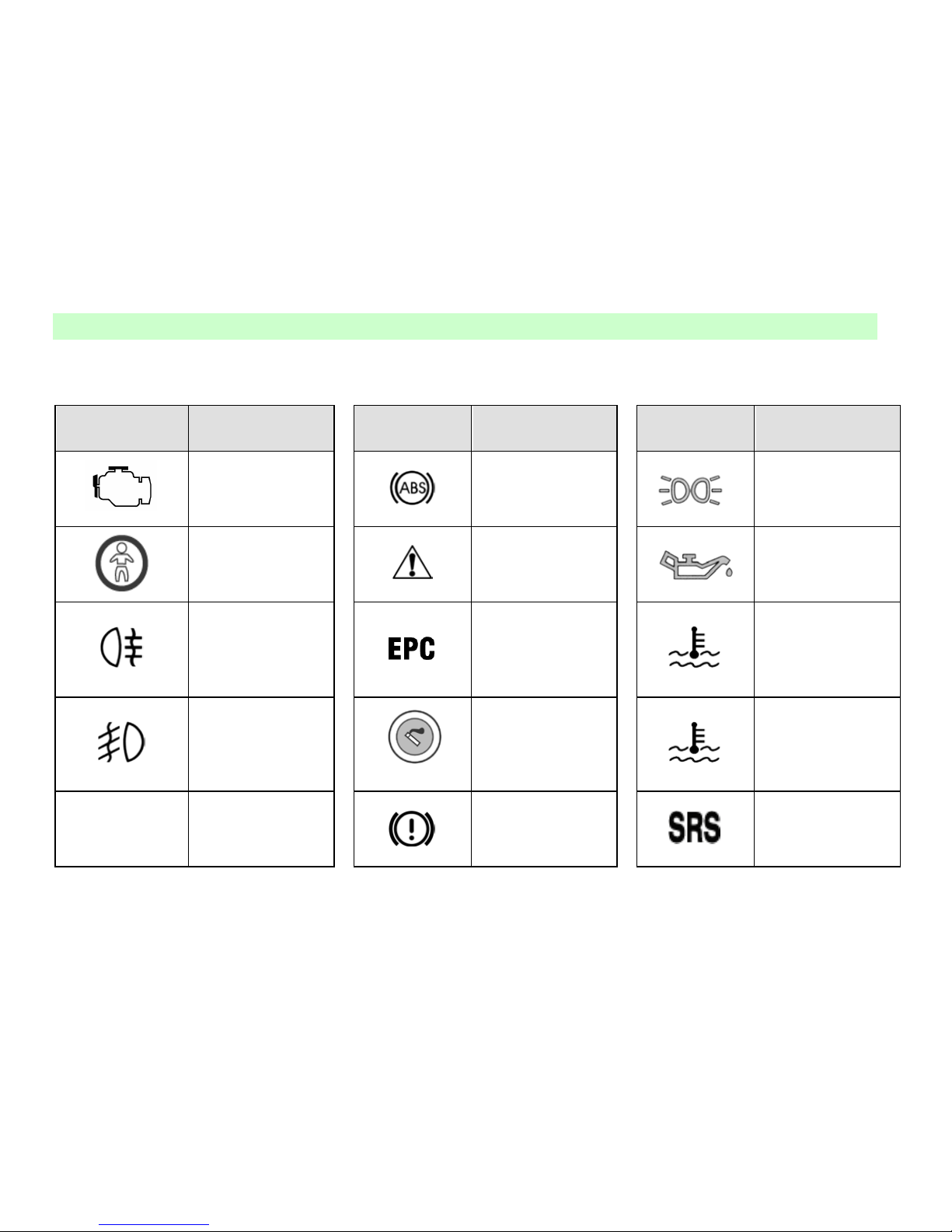
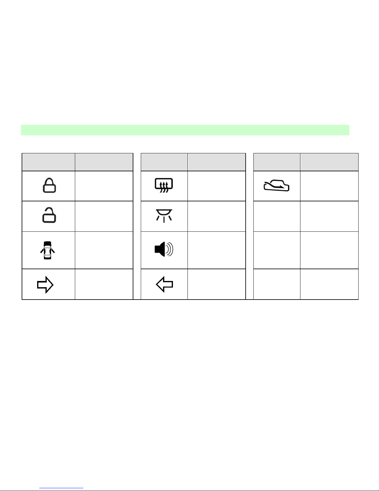
Desc r iption of Common Symbols on Vehicle
Symbol Definition
Symbol Definition Symbol Definition
CHECK ENGINE
Antilock braking
system
Position light
Glass Drive Switch
Prohibitted
Safety warning
Engine oil pressure
warning li ght
Rear Fog Lamp
Throttle fault
indicator lamp
Coolant temperature
overhigh warning
light (red)
Front Fog Lamp
Cigarette Lighter
Coolant temperature
normal indicator
(green)
A/C
Air Conditioning
System
Brake system
warning li ght
Identification of air
bag
Page 15
Notices Before Drive
6
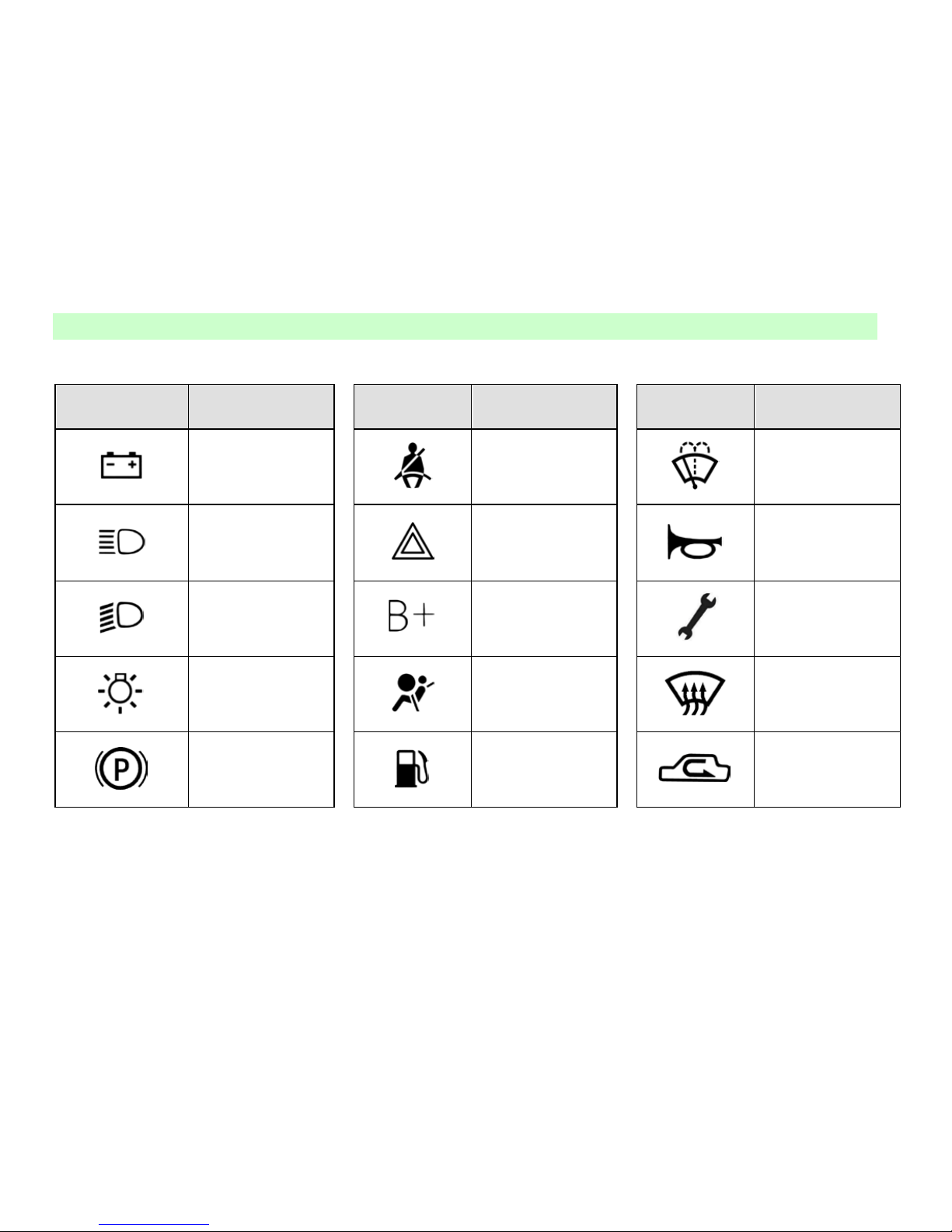
Symbol Definition Symbol Definition Symbol Definition
Battery
Seat belt ready
Windshield washing
High beam
Hazard warning
flasher
Horn
Low beam
Batter y positive
Vehicle maintenance
indicator
Headlamp switch
Air bag fault
indicator light
Windshield
defrosting/defogging
Parking brake
indicator light
Fuel level low
Inner circulating air
Page 16
Notices Before Drive
7
Symbol Definition Symbol Definition Symbol Definition
Lockup indicator
Rear windshield
heating indicat or
Outer circulating air
Unlock indicator
Indicator for interior
lamp switch
Warning light for
door and trunk lid
open
Audible alarm
Right turn signal
lamp indicator
Left turn signal
lamp indicator
Page 17

Notices Before Drive
8
Notices Before Drive
Page 18

Notices Before Drive
9
Page 19

Notices Before Drive
10
Operations in the phase o f
test-drive
Some simple protective measures should be
fo llowed durin g t he initial running-in period
which can improve
drivability and
economy of the vehicle
and prolo ng i ts
service lif e.
Do not run engin e in hi gh s p eed at
idle;
Do not overload engine
possibly
while us ing
transmission drive;
Avoid using emergency brake
unless there is an emergency;
Avoid st epping down accelerator at
neutral during start;
The engine requires a period of
time for warming-up after start
Avoid drawing other cars;
Avoid any ri gor operations such as
emer gent st art, sudde n accelerat ion
and long-time high speed running
which will not only do harm to t he
engine, but also increase fuel and
oil consumption and even damage
engine compone nt s . A nd esp ecially
try to avoid stepping down
accelerator p edal to the end under
bottom gear.
Befor e entering the car
Inspect if windows, outside
rearview mirror and lamps is clean
or damaged;
Inspect if tire pressure is normal;
Inspect
if all vehicle lights are
normal;
Watch if there is any obstacles
behind the car;
Inspect
if fuel pipes leak
Inspect
if engine oil level and
other fluid level are within
standard range.
Before d ri ving
Make sure that you have known the
condition and equipments of the
vehicle, and how to operate them
safely.
Adjust the position of the seat;
Adjust the angle of interior and
outside mir r ors on the car.
Insure that all p as s engers ha ve t ied
up their seat belt.
When turning t he ign it ion switch to
position II, you should inspect
whether the alarm lights have
gone
out after automatic detection.
!Notice
Please inspe ct if windo ws,
rear windshield, all
lamps, signal
transmission system and
warning indicator are
normal. Do not put
a nything o n rea r luggage
Page 20
Notices Before Drive
11
rack, or it will limit the
back line of sight and
hurt the passengers by
the move me nt o f lugga ge
while emergent stopping
or shocking.
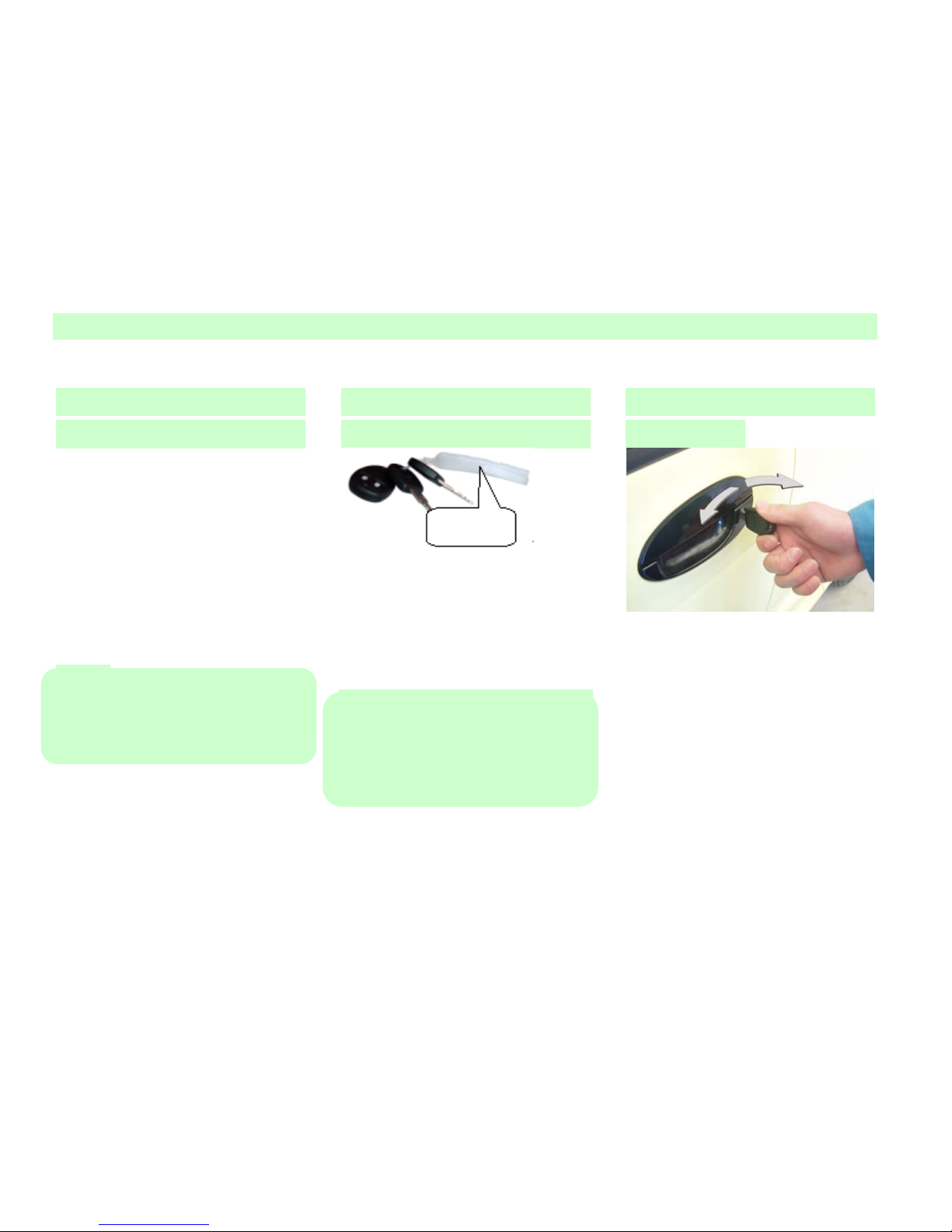
Keys
Equip two keys adapted to all
lockholes on the car, and one of the m
is a spare key. Key code ca rd of the
key i s pasted on the number cap. Do
not leave code card in the car for car’s
safety. Put it at a safe place an d
remember key code. Do not record key
code i n the car to pre ven t anyone who
got this code to copy the key without
permission.
!Notice
Do not leave the key in the car.
1. Lock the car.
2. Take the key with you.
Locks
You can open and lock the front door
from outside with the equipped key.
Rotate the key counterclockwise to
open
t he door an d clockwise to clo se it.
!Notice
Before leavin g y our car, ensure all of the
doors and rear compartment lid have been
locked when there is no one to take
charge it.
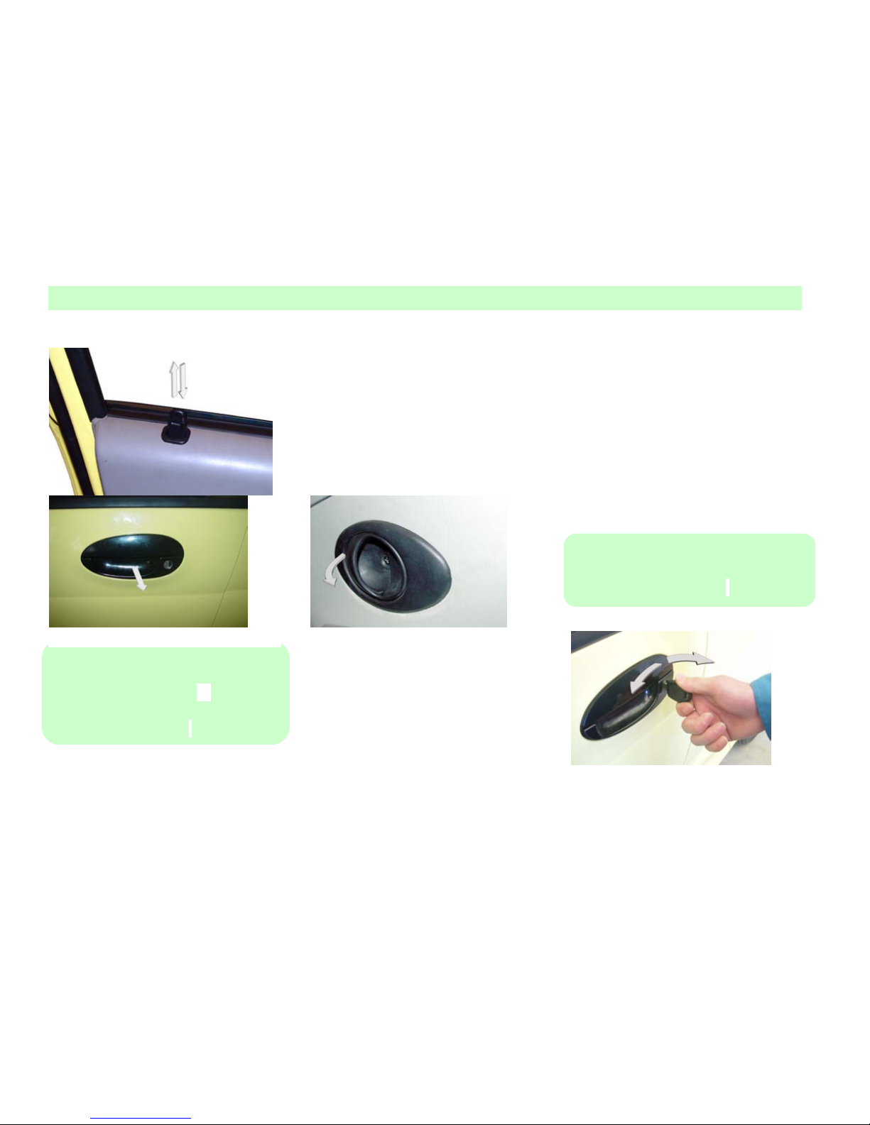
You can lock or open the door with the
lock button on the side of the windows.
Excep t t he left -front door, you can lock
all of the doors from out side by p ress ing
the lock button and closing the door.
When you leave the car, you can only
lock the left front door from outside with
the key.
Lock
Unlock
Key No.
Page 21
Notices Before Drive
12
When opening the door from outside, you
can pull the outer handle.
When opening the door from inside, y ou
can pull the inner handle.
!Notice
Do not leave children or animals alone in
the car. 1.To prevent asp hyxiation
especially in hot seasons.
2.They may move the car unexpectedly.
Ce ntr al Control Lock
Central control lock is controlled by
the driver side door (left-front door).
When locking or opening the driver
door (left-front door) with key or
pressing the lock button, all the doors
can be locked or opened
simultaneously.
!Notice
Before leavin g t he car, lock the left-front
door when there is no one to take charge.
Lock
Unlock
Page 22
Notices Before Drive
13
Children Security Lock
On each of the back door there is a
children security lock which can
prevent the passengers at the back,
especially the children to open the door
from inside unexpectedly by pulling
th e inn er ha n d le.
Press dow n the metal lo ck p in under the
lock of each back door, then the door can
not be opened from inside and the handle
is also locked, t hat is, w hen the children
security lock has been locked, the inner
handle can not open the door.
!Notice
Children at the backseat may open the
back door unexpectedly.
1. M ove t he children security loc k p in
to the locking position.
2. Do not p ull t he inner handle of the
door when the children security lock
has been locked so as to prevent any
damage to the handle.
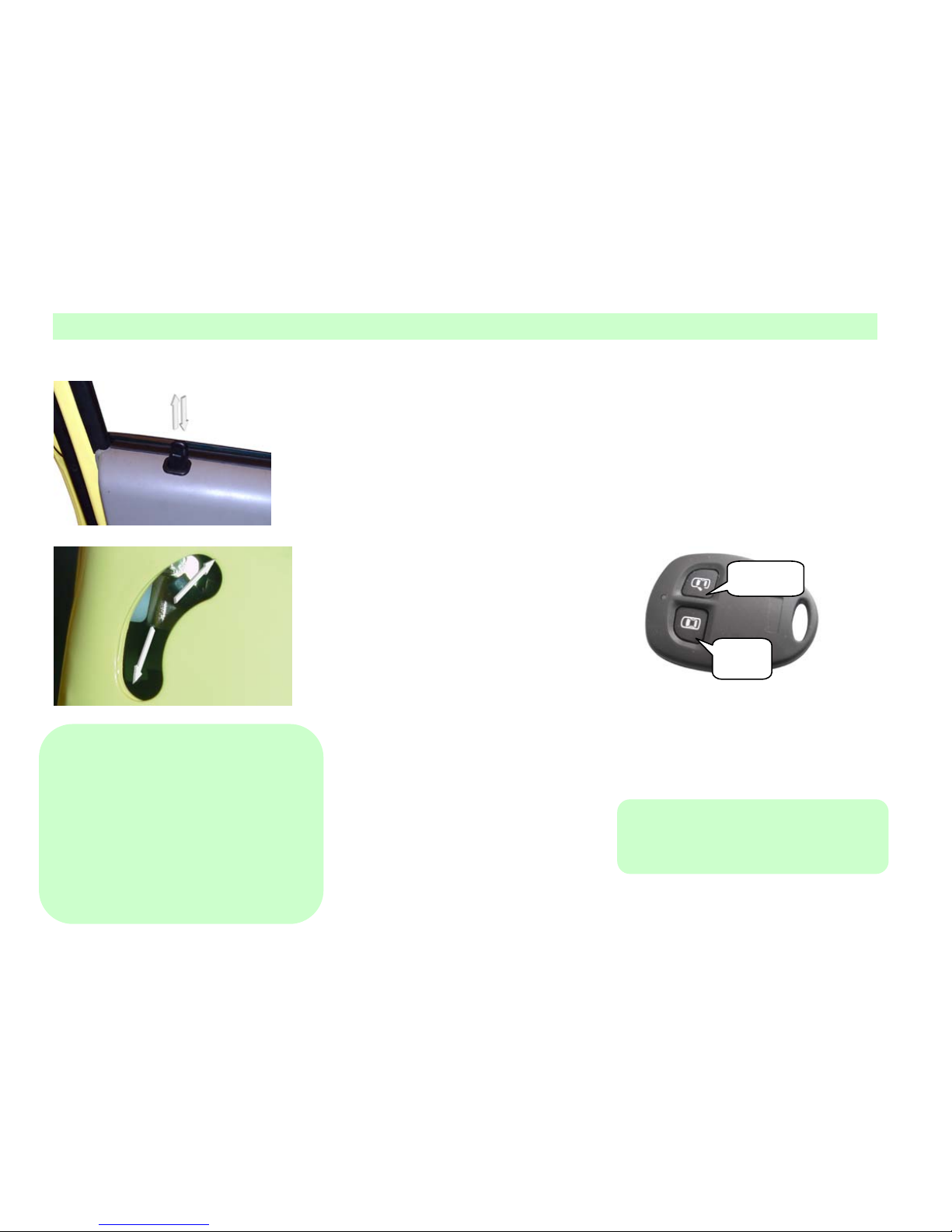
Burglarproof No-Key
Entering Sys t e m
No-Key Ente ring S ystem can open the
door in a distance of 6 meters through
a se nsor. The LBD on the sensor lights
up to indicate the sensor in operation.
1、LOCK button: Lock all doors. When
danger signal light has glittered 3 times,
the burglarproof system is in
operation.
2、UNLOCK button: Open all doors.
When danger signal light glittered
twice, the burglarproof system is
closed.
!Notice
The effective range of the sensor will
change with environment.
Lock
Unlock
Page 23
Notices Before Drive
14
Activating door Lock and
Burglarproof Mode
Close all the windows;
Turn igniti on key to B, and pull
out the key;
Let all passengers get off the car.
Close all doors and hoods and
trunk lid.
Press down the LOCK button on
the sensor so as to lock all of the
doors. Those cars equipped with
powe r wi ndow
lifting system will
automatically raise all windows,
and at the same time hazard
warning lamp glitters 3 times and
the burglarproof mode is started.
If the i gni tion switch is set on II,
the burglarproof mode does not
work but the function of locki ng
still work normally.
!Notice
If you use key to lock the door, the
burglarproof mode can not be activated.
Pleas e us e s ens or if y ou want t o act ivat e
that mode.
Relief of Door Lock and
Burglarproof Mode
Press UNLOCK button on the sensor
to unlock all doors and hazard
warning lamp glitters twice at the same
time, burglarproof mode is exited.
Normal status: If there is not
interruption and fault, haz ard-warning
lamp will glitter twice, and the interval
between each glitter is 0.5 sec.
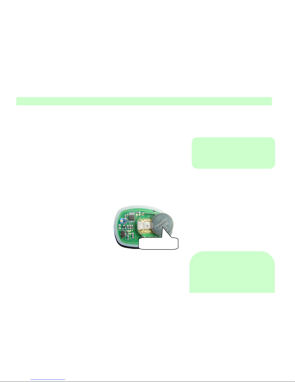
Replace Sensor Battery:
Sensor indicator lamp does not glitter,
which means that battery needs to be
replaced, but sensor can still be used for a
period of time.
Replace a Panasonic CR2032 b att ery (or
other equivalent 3V battery ) in following
process:
Insert a screwdriver into the gap
between the sensor cover and
separate the 2 covers of the sensor.
Insert a screwdriver into the gap
between the sensor covers and
separate them.
Pull the sensor power supply out of
the cover and disconnect the
attachments carefully and p ut it at a
clean place.
Install new battery, make sure that
the polarity is correctly placed
(cathode facing bottom)
Install the att achments and p ut the
sensor power supply into the cover.
Close the two covers of sensor.
Check whether the sensor can work
properly.
!Notice
T he w ast e Li-bat tery will do harm to t he
Accumu
Battery
Page 24
Notices Before Drive
15
environment:
Do not drop the waste battery as
li vin g ga r ba ge ;
Dispose the waste battery according
to the local reclaim regulations.
Sensor might be damaged
Do not reverse the polarity of the
sensor
Prevent falling
Do not lay anything heavy on the
sensor
Do not let the sensor touch water or
be exposed to straight sunlight
If the sensor get wet, clean it with a
soft piece of cloth
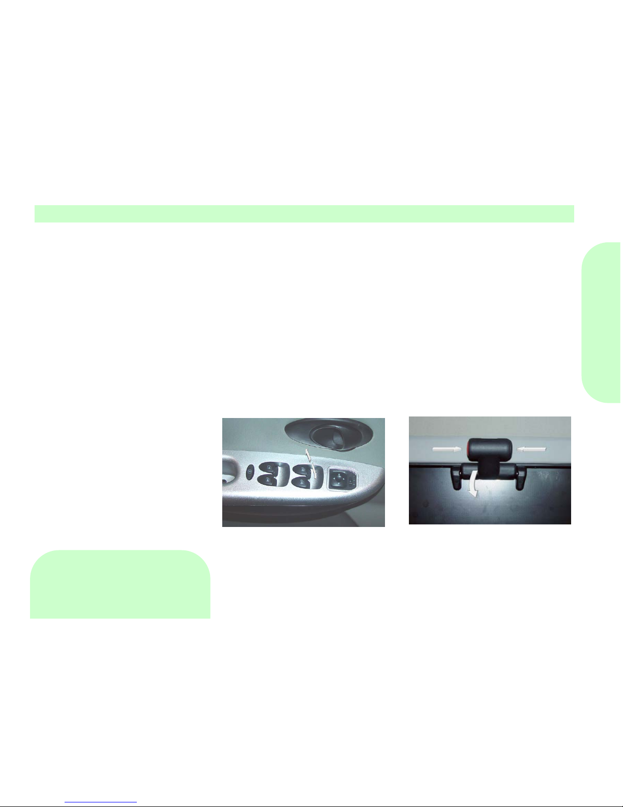
Po wer W i ndo w Sw itch
When t he ign ition sw itch is set to “II”,
we can operate power window through
power window switch on the inner handle.
Press down the top of switch, window
glass will fall. while pulling up the top of
swit ch, window glass will rise. Loose the
switch when window glass reache s t o an
ideal position.
!Notice
Pull off the ignition key when
leavin g t he car s o as t o p revent any
unnecessary hurt to the children
caused by t heir operation when left
alone.
Do not sp read hands, head or any
other thing out of the window.
The unexpected close of the window
will cause serious damage, so do
not let the children play with the
electric window switch.
Manual Sunshade-Roof
Op erate with your hands to tilt sun shade
roof up.
Before doing this, check whether roof
antenna is at a proper position.
Pull forward to open it.
Press the button and raise
sunshade
roof
to an ideal position.
Press the button again and pull down
sunshade roof handle to close the
suns hade roof.
!Notice
Page 25

Notices Before Drive
16
The s un shading t op can not op en when
there is sundries on it.
Clean the top before open it.
Eliminate the water drops, snow,
ice and sands before opening the
sun shading top.
Do not place anyt hing heave on the
sun shading top or around. Please
clos e t he sun s hading when leaving
the car alone.
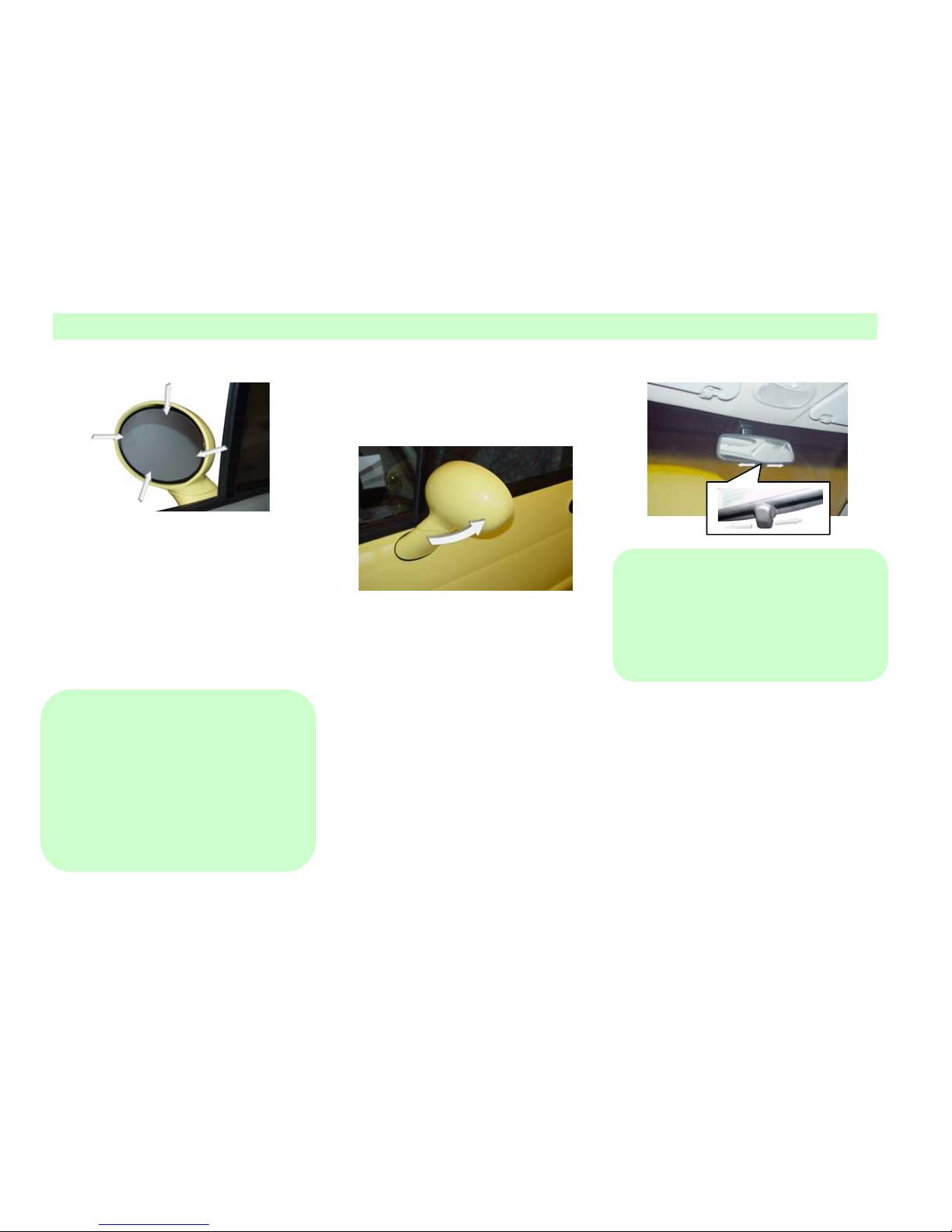
Outer Rearview Mirror
Adjust the outer rearview mirror to see
both sides of the road clearly and confirm
the p osition of the things y ou s aw. Move
the outer rearview mirror to an ideal
position (for the movable lens) or use
adjustment button (for the joystick)
directly so as to adjust t he angle of the
mirror.
Page 26
Notices Before Drive
17
The outer rearview mirror at the
passenger side is a convex, so things you
see in it will be closer than what it is
actually. Use this mirror you can watch
much wide of the road behind you. When
entering a narrow roadway or washing
your cars, you can push back the mirror
which will properly collapse to the body.
!Notice
The around line of sight might be
weakened which will increase the
p oss ibilit y of accidents . P leas e adjus t t he
angle of the rearview mirror and check
whether there is any damage on the
mirror. Use defroster, atomizer and
blower to eliminate the ice and frost.
The outer rearview mirror shows thing
closer, so use inner rearview mirror to
clear t he rear line of si ght. Do not block
the rearview range from the driver seat.
Inner Rearvie w M i rror
The inner rearv iew mirror can be moved
up and down as well as left and r ight so
as to get the best line of sight.
There are 2 p ositions for the inner rear
view mirror which are daytime and night.
During daytime the high speed joystick
should be moved to day t ime p osit ion. At
night the joyst ick should be adjusted to
“Night ” position to weaken the beam of
the headlight of the cars behind.
!Notice
To maintain the rearview range of the
driver, choose daytime and high speed for
the best line of sight . If y ou choose night
p osition, it will decrease the definition of
the rearview mirror.
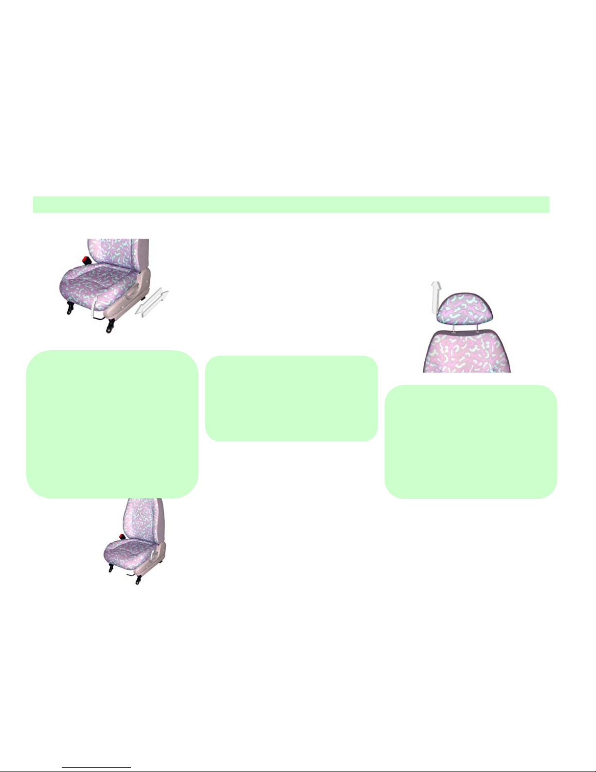
Front Seat Slipping
Adjustment
Draw up the control joystick under the
front s eat and slip it to an ideal pos ition,
then loose the joystick.
Page 27
Notices Before Drive
18
!Notice
Do not adjust the driver seat during
driving so as to prevent the car to be out
of control.
The looseness of the seat belt will
reduce its prot ection function.
Adjust t he front seats before tying
the seat belt.
Do
not
leave
anyt hing under the seat which will
disturb the seat adjustment organ.
Front Seat Til t A djustment
Pull up the joy stick at the side of the s eat
to adjust the backrest to an ideal angle,
and then loose the joystick.
!Notice
Do not adjust t he backrest w hen driving.
Do not tilt the seat too much to prevent
the seat belt slide. Adjust the backrest to a
vertical angle for max protection
functions.
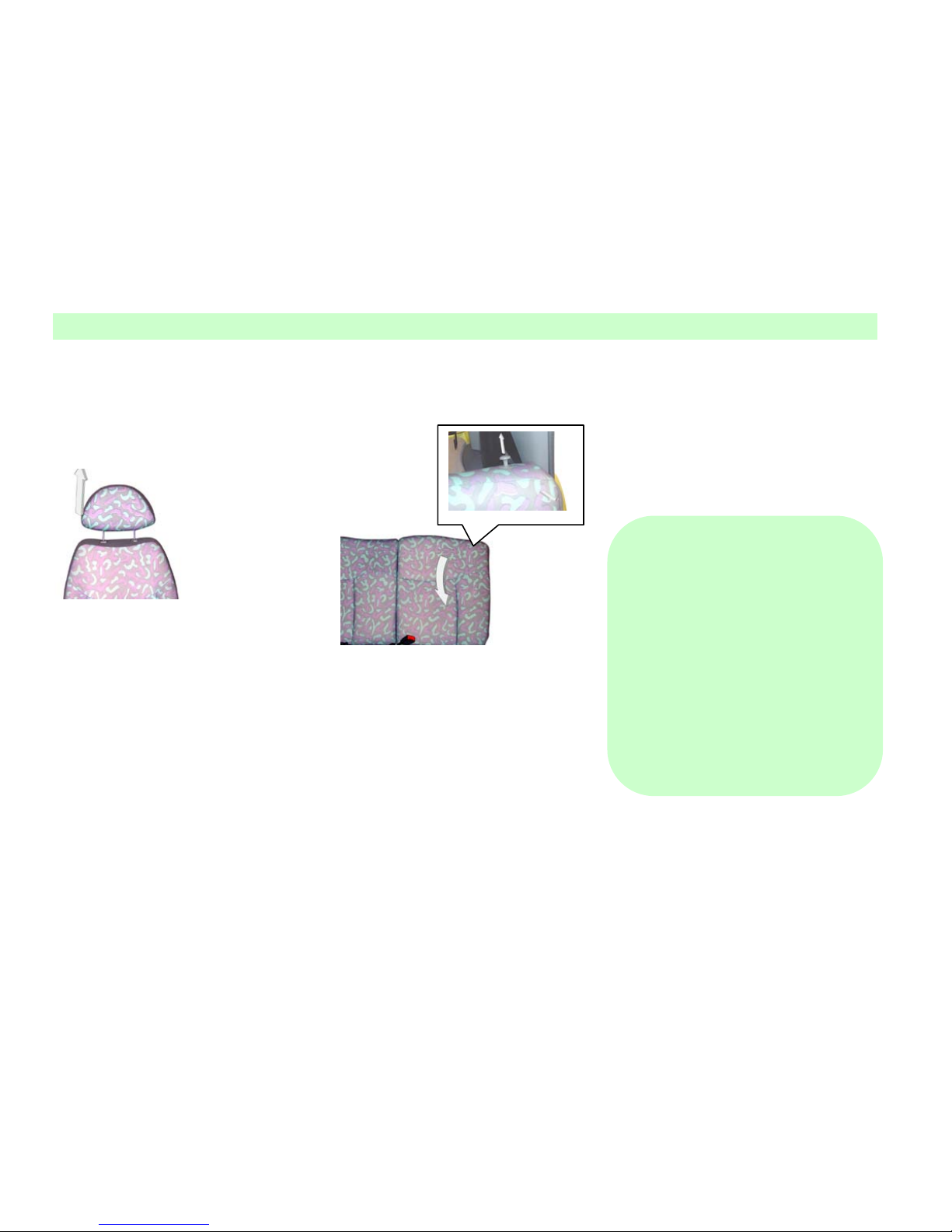
Headrest
The headrest is des igned t o decrease t he
danger of hurting the cervix. You can
adjust its altitude by p ulling up or p ress
down it.
!Notice
The headrest is to p revent any hurt. Do
not drive before adjusting it. Adjust its
altitude so that the back of the head can
touch the middle part of the headrest.
After the adjust ment , fix the p osition of
the headrest. Please make sure the
headrest has been adjusted and fixed to
the right position before drive.
Disassembly the headrest:
Pull the headrest up t o the highest
position.
Insert a small screwdriver into the
Page 28
Notices Before Drive
19
notch of the left guide bushing.
Touch the head of the stop perch
with the screwdriver and pull the
headrest out from the bushing.
F olding Backs eat Backrest
Fold down the backrest to increase the
space of the trunk.
Folding process:
Lift the seat cushion to vertical.
Pull up t he lock but ton on t he seat
backrest, loose the backrest, and
fold in the direction of front and
down.
If you want the seat backrest get
back to the vertical position, just
pull up the backrest and pull the
backre st to the pro per position.
If y ou want the cushion back t o the
original position, just put it to a
prop er position and pull and press
to the lock position.
!Notice
Do not p ile any goods on the b ack
seat because it m ay cause dama ge
when the goods moving.
Not ice when the backs eat get back
to the vertical position:
1. Checks whether the seat backrest
and seat cushion have been locked at
a firm position by pushing or
pulling.
2. Ensure that the seatbelt is not
tw isted or stuck in the seat backrest,
and place it at a proper position.
Page 29

Notices Before Drive
20
Seat Belt Precaution
Measure
To protect the passenger, the entire
passenger must correctly use seatbelt
during dr ivin g. One seatbelt for only one
p erson, and those children under 6 y ears
old are not suitable to use seatbelt, and
y ou should assembly proper child seat or
assistant cushion for your child.
!Notice
Passengers may get hurt in a collision or
emergent st op , so they must use seatbelt
at anytime. Do not use one belt by several
people. Do not put anything hard or
fragile in the pocket or clothes clinging to
t he s eat belt . M isus age of t he s eatbe lt will
cause serious damage. Do not change the
seatbelt or attach any equipment which
will affect the employment of the seatbelt.
The worn seatbelt cannot be used any
more which will probably affect the
safety of the people.
When us ing a seatbelt, p lease use it and
maintain the belt and child protection
system with correct method in order to
decreas e t he damage to the p eople in a
collision or emergent stop.
!Notice
M isusage of the seatbelt may cause
damage or even death to people. The
seatbelt should be firm and the seat
backrest should be adjusted to vertical.
Do not lean on the backrest w hen driving
the car. D o not us e it if t he belt tw isted.
Do not tie the belt cross down t he arm
which should be at the middle of the
shoulder, and also do not w rap it around
the head or neck. Tie it clinging t o the
buttocks but not waist. If the seatbelt tied
too loosely, it will increase the rate of
hurt to people because the body will slide
under a loose belt. The loose button of
the seat belt should face outside. Insert
the pin of the belt into the appointed
connection lock. Do not p ut anything at
the shield board hatch of the seatbelt to
prevent it from getting stuck. If it gets
stuck, the only way is to entangle the
entire belt int o the reel and then p ull the
ideal length out according to the need.
Maintenance of the Seat
Belt
The s eat belt s houl d be maint ain ed cl ean
and dry, avoiding any pollution by
polishing composition, oil, chemical,
especially by t he acid of t he accumulator.
Please wash with litmusless soap . D o not
blanch or dye the belt which will
p robably do harm to the belt . Prevent the
seat belt from any sharp-edged things.
Check the belt re gularly for any dama ge
and replace thos e worn ones in time. The
over strained belt should be replaced after
an accident. Chery suggests replacing all
the components of the seatbelt after a
collision. But after a slight collision, if
the Chery Service Station does not check
out any damage, and all the components
can work normally, there is no need to
replace. If there is any damage or false
with the seat belt and its components
which has not been used in an accident,
they also need to be tested and replaced if
necessary.
Page 30

Notices Before Drive
21
!Notice
The worn seat belt may
c ause serious damage, s o che ck the
seat belt components regularly.
After a c ollis ion, you mus t take all
the seat belt components to the
Chery Service Station for a check
and replace them according to the
need. If t he belt has been damaged
or polluted, it must be replaced.
After a serious collision, the seat
belt components must be replaced
no matter there is evident damage
or not. If the s eat belt is not suitable,
it will arouse much more serious
damage. Do not c hange seatbelt at
will.
For pregnant woman
Suggest the p regnant woman to refer to
the doctors for the usage before using the
seatbelt.
!Notice
In order to avoid any damage to the
pregnant woman and the infant during the
travel, please use “three points on the
cross” connected seatbelt if p ossible and
tie it as low as possible to cross the entire
pregnant position (refer to the doctor).
Children Protection
System
Be sure to use p roper children protection
system when bringing any infants or
children.
The children p rotection system should be
assembled on the seat according to the
height and weight of the child.
Status shows that proper children
protection system will be safer if it is
assembled on the back seat rather than
the front seat.
!Notice
Infants and children should be kept in the
children protection system. Do not
assemble the backward children
prot ection system on the front seat with
air bag.
If the children protection system is
assembled on the front seat, child will
probably be seriously hurt when the air
bag char ged and inflated.
Please assemble the children protection
system on the back seat as possible as
you can. If it must be ass embled on the
front passenger seat, the seat should be
adjusted back as possible.
!Notice
Assemble the children protection
syst em according t o the instruction
provided by the manufacturer.
Tie is firmly or remove it when
there is no use.
Do not hold your child in arm when
riding on the car.
If the children protection system is too
small for your child, just let him or her sit
on the back seat and tie up the seat belt. If
the child sit at the p osition wit h crossed
seat belt, and the belt is close to his or her
face or neck, y ou should mov e the child
to the middle, that is lean to the inner part
of the belt, and p ut y our child at a place
without crossed seat belt if possible.
Page 31

Notices Before Drive
22
T hre e point s eat bel t
There is three p oints seat belt with brake
limit on every Chery car. Although the
spring-plugged seat belt is cooperated
well, the body is permitted to move freely
during a smooth running.
There is a sens itive reel on t he seat belt
which is used to lock the seat belt in
violent acceleration and deceleration.
Please do not test the lock of the seat belt
by rush forward forcibly. This kind of
seat belt does not need to adjust the
length which will automatically adjust
according to the movement of the
p assenger. But it w ill automatically lock
to limit the movement of t he body of the
passenger in a sudden collision or
impulsion.
Usin g the Seat Belt
Pull the seat belt out from the reel and tie
it to the body ensuring the belt is not
tw isted, and insert t he metal p in ( 1) into
the buckle loop (2).
!Notice
If it gets stuck, the only way is to
entangle the entire belt into the reel and
then pull the ideal length out according to
the need.
If you want to offload the seat belt, just
p ress the red button on the ouch, the belt
will retract automatically.
Connecting Seat Belt
Connecting seat belt is assembled in the
middle of t he b ack seat. Ins ert t he met al
pin into the ouch until locked. If you
want t o draw out the seat belt, just press
the metal pin on t he seat belt at p rop er
angle and strain the belt. If y ou want to
shorten the belt, just p ull the metal p in
out at the free end of the belt, and st rain
the loose part with a clincher.
Put the connecting seat belt to the
buttocks.
Press the red button on the ouch to
offload the seat belt. “CENTRE” is
marked on the ouch and metal p in of the
back seat center connecting seat belt.
Please check this mark before use the
belt.
①
②
Page 32

Notices Before Drive
23
!Notice
M is using t he s eat belt may caus e s erious
damage. Put the connecting belt on the
butt ocks comfortably rather than on the
stomach or the waist. T he worn or over
strained seat belt will probably cause
serious damage. Do not insert the metal
pin into an improper ouch forcibly. When
straining the backseat seat belt, ensure the
metal pin has been inserted into a p rop er
ouch to obtain the max protection
function.
Air Bag
SRS can provide additional protection for
the driver and pas s enger at t he fr ont s eat
in an acc ident to prevent t heir head and
chest from injury.
When serious collision in face or in the
front range of 30
, the air bag will
charge and expand, and sound of
explosion will be heard with a little
smoke which is harmless.
There is no security system can p rovide
entire protection in a serious collision.
You cannot judge whether the air bag has
exp anded or not only with naked ey es. In
some accidents which the air bag did not
expand, the excess damage proved that
the car had absorbed a great deal of
bounce energy, so there is no need for air
bag. In other serious collision accidences,
suc h as coll is ion at t he ch as sis, t he body
may not be damaged in large scale but
also will cause the air bag explode.
!Notice
Pleas e t ie up t he seat be lt for the s ake of
y our safety. SRS can only be used as the
assistant equipment of the seat belt. Make
bold to disassemble air bag components
might cause damage to people. Do not
modify the original components of the air
bag. It will be very dangerous and cause
damage to p eop le if y ou dispose the air
bag without permission. The disposal and
replacement must be carried out by Chery
Service Station. Do not lie anything on
the st eering wheel and instrument p anel
to avoid limitation of its protection
function.
Page 33

Notices Before Drive
24
The air bag will not operate under the
following circumstances:
Tracing t ail, side bu mping, side turn and
without enough bumping intensity.
Cab air bag
The driver air bag is assembled at the
cent ral f l an ge of the s t eerin g wheel. The
air bag will ch arge and exp and in several
seconds after collision and form a safe air
cushion for the driver. The air bag can
exp and wit h enough p ow er and sp eed, so
it is very imp ortant to adjust the driver
seat and backrest properly. Adjust the
position of the seat that the hands can
easily touch t he steering wheel o nly in a
small angle.
!Notice
Do not repair the steering wheel; turn
shaft and air bag without authorization
which only can be carried out by Chery
Service Station.
Front passenger air bag
In some cars, t he air bag is ass embled at
the side of the passenger or on the t op of
the toolbox. T his air bag is so bi g that it
can charge and expand with enough
power. If the front passenger sit in
improp er position or does not tie t he seat
belt correctly, he or she will p robably be
seriously injured by t he air bag. So the
p assenger should move t he s eat back and
sit behind as possible.
!Notice
Children will probably be seriously
injured by the air bag in an accident. If
you assemble the children protection
system at the front seat, it will be bumped
by the air bag. So make sure to ass emble
the children protection system at the back
seat.
You should assemble the children
p rotection sys tem at t he back seat. If t he
system is too small for your child, just let
him sit at the back seat and tie up the seat
belt.
!Notice
Do not repair the instrument panel
without authorization which only can be
carried out by Chery Service Station.
Trunk C over
Insert the key into the key less entry and
turn it clockwise to op en t he trunk cover.
Put down or push down the cover and
close and lock it.
!Notice
The exhaust gas is harmful. After opening
the trunk cover, turn off the engine to
avoid the gas coming into the cab.
Page 34

Notices Before Drive
25
Trunk cover unlock
joystick
Pull up the trunk cover unlock joy stick at
the left side under the driver seat to open
the trunk cover.
!Notice
It w ill cause accident if y ou drive the car
with the trunk cover open which will
block your line of sight.So1. Do not
op erate the Trunk cover unlock joy st ick;
2. Do not drive with the trunk cover open.
Fuel fill door unlock
joystick
The fuel fill door lies on the right back
board of the car.
The fuel fill door unlock joys tick lies on
the left side under the driver seat.
Notice when filling the fuel:
1. Shut down the engine.
2. Pull up the fuel fill door unlock
joystick to open the fuel fill door.
3. Turn in counterclockwise to open the
fill cap.
4. Turn the cap clockwise after filling and
screw down, then close the fuel fill door.
Page 35

Notices Before Drive
26
!Notice
The fuel steam is flammable. Shut down
the engine and do not s moke or produce
fire and sparkle to avoid fire.
Do not use plumbic gasoline to the
non-plumbic gas cars to avoid any
damage to the engine and exhaust system.
Gasoline will damage t he painting. If the
gasoline spatters on to the painting, wash
it with cold water immediately. The
gasoline in the fuel tank might be
compressed. You can screw loose the fuel
tank cap slowly. In cold weather, the fuel
fill door may not be op ened easily; y ou
can open it by pushing or knocking it.
Eng ine Cop ing
1. Pull the unlock handle at t he left s ide
under the instrument panel to open the
engine coping lock.
2. Push upward of the claw to lift the
engine coping.
Page 36

Notices Before Drive
27
3. Insert one end of the knighthead into
the hole beside the en gine room to brace
the coping.
4. Press t he knight head int o the clamp to
avoid vibration before closing the coping.
5. Lay down the coping and let it fall
from about 30cm (1 inch) height. Close
the coping and shake the edge of it to
ensure it has been locked.
!Notice
Opening the engine coping in traveling
will cause accident which would block
the front line of sight. Pull the edge of the
coping to check whether it has been
completely closed before driving. Do not
operate the engine coping unlock handle
during driving. Do not drive with the
coping lifted. If the coping is op en, the
car still can be st arted. So before loose
the coping unlock ouch, pull off the
ign ition key and set t he transmission at
1-sp eed or back-up and p ull the parking
brake. Wh en t he en gin e is runn ing, open
the engine coping and the running
components bare at this time, do not wear
loose clothes or let hands and hair to
touch the running components to avoid
any unnecessary damage.
Page 37

Notices Before Drive
28
Page 38

Notices Before Drive
29
Page 39

Start and Operation
30
Start and Operation
Page 40

Start and Operation
31
Page 41

Start and Operation
32
F uel S uggestion
Use non-plumbic gasoline with high
quality for commercial purpose. The
quality of gasoline decisively affects t he
dynamic, drive performance and life of
t he engin e. And the additive is import ant
to the fuel. Please use non-plumbic
gasoline with additive of high quality. If
the octane rating is too low, it will cause
engine explosion. Chery will not be
responsible for any loss caused by
misusage of the fuel. Please use fuel with
high quality.
! CAUTION:
DO NOT apply the leaded gasoline to the
vehicle powered by the unleaded gasoline,
ot her wis e it may da ma ge t he engine and
exhaus t sy stem, and any damage caus ed
herein is without warranty. To prevent the
unintended leaded gasoline refilling, the
leaded gasoline pipe can’t be inserted into
the unleaded gasoline filler port.
Operation at overseas
If y ou drive Chery cars in other count ry,
make sure to:
Obey the laws and security
regulation.
Affirm whether there is p rop er fuel
provided.
When using oil tank and oil storage
containers (especially those
unp rofessional fillin g equipments ) to fill,
the st orage pump and the tube must be
earthed properly for the sake of safety.
When the fuel flows under a certain
pressure, a large deal of static will
p roduced if the filling tube is not earthed
(especially p lastic pipe)
Be advised to use earthed filling
equipments and tube. The container
should be earthed in unprofessional
filling operation.
I gnition Switch
There are 4 positions at the ignition
switch on the right of the turning pole: B,
I, II and III.
B pos ition
Pull out the key to lock the pole.
Turn the steering wheel till it locked.
To conveniently turn the key when
opening the lock, you can turn the
steering wheel counterclockwise to let the
key turning to “I” position.
I position
Can not lock the steering wheel but can
shut down the engine.
Operate normally at this position just like
operating radio and cigarette lighter.
lI position
Can start ignit ion sy stem and accessories
of the app liances.
Page 42

Start and Operation
33
III position
Can start motor to drive the engine.
Loose the key after starting the engine,
the key will back to “II” position
automatically
!Notice
Do not place the key to “I” or “II”
posit ion when the engine is not running
to avoid electric loss of the accumulator.
Do not p ull off or turn the key in driving
to avoid the car out of control.
Befor e starting t he engine
Make sure there is no obstacles
around the car.
The maintenance projects in this
manual should be implemented
regularly, for example:
1、Check the position of the fuel;
2、Check whether the windows and lights
are clean
3、Wat ch the app earance of the tire and
check the air pressure
4、Adjust the position of the seat and
headrest.
5、Adjust the angle of the inner and outer
view mirror.
6、Tie the seat belt.
Turn t he ignition switch to “II” position
to check the p erformance of t he warning
lights.
Start the engine
1. Turn the ignition switch to the III
position, DO NOT step on the accelerator
pedal, and immediately loosen the key
after the st artup of t he engine and then
the key returns
to the II position.
2. If the temp erature is above -12℃ and
the engine fails to start up within 5 s
when the engine starts up in the first time,
turn the key to the B position, and ret ry
after waiting for 10 s.
3. If the temp erature is below -12℃ and
the engine fails to start up within 15 s
when the engine starts up in the first time,
turn the key to the B position, and ret ry
Neutr a l Pos ition
Page 43

Start and Operation
34
after waiting for 10 s.
If the engine fails to start up in the
continuous two times, step on the
acce lerat or p edal t o its end and keep it in
the position, turn the key to the III
p os ition, and then loosen the key after the
startup of the engine, subsequently, with
the speedup of the engine, slowly release
the accelerator pedal.
4. For the vehicle equipped with the AMT
transmission, let the engine oper at e at t he
idle speed for several seconds after
st artup, st ep on the foot brake, loosen t he
hand brake, shift t o t he driving gear, and
then drive the vehicle.
5. For the vehicle equipped with the
manual transmission, let the engine
operate at the idle speed for several
seconds after startup, step on t he clutch,
shift t o the driving gear, release the hand
brake, and then drive the vehicle.
! CAUTION:
Before the gear shifting, please pull up
the hand brake or step on the foot brake,
otherwise, when shifting the gear, the
vehicle may move to cause the damage or
injury.
6. The ambient t emperature condition is
-25℃-40℃ for the normal startup and
operation of the engine (when the
ambient temperature is not within this
range, it may result in the difficulty to
start up the engine. This is a normal
case).
Warming-up
In cold weather, let the engine run in idle
for 30 min. after starting and t hen drive a
distance with middle speed.
!Notice
The exhaust system will be damaged
under high temperature. So the idle
running can not exceed 5 min. If the
engine failed start , just step slowly down
the accelerate panel and maintain, then
start the engine.
Operation of the Man ual
Transmission
Step down the clutch completely and
move the shift joystick, and loose the
clutch after shift.
!Notice
Do not shift in driving. When the car
stop s completely, back-up shift can be
used to avoid any damage to the
transmission. Do not lay your foot on the
clutch panel to avoid any damage to t he
clutch.
Page 44

Start and Operation
35
Operation procedure to start a
engine with AMT transmission
(
)
Keep t he transmission gear position on
the N gear, 1st or 2
nd
Turn the key to the position “III”, and
DO NOT st ep on t he acceler at or peda l t o
st ar t t he engin e. After the en gine s tart s,
release the key. If the engine fails to start,
repeat the procedure above.
gear before the
engine st arts. DO NOT step on the brake
to start the engin e when the transmission
is placed in N gear position, otherwise the
engine fails to start.
! CAUTION: The starter can’t
operate for above 10 s every time,
otherwise, it may damage the st arter. If
the engine still fails to s tart, wait for 15 s
and then have a try (for the vehicle
equipped with the automatic transmission,
turn the ignition switch, wait for 10 s and
then have a try)
Operation procedure of AMT
transmi ssion (
)
R = Reverse
N = Neutral
Manual gearshift mode
+ = Upshift
- = Downshift
1. Shift to the R position only
aft er the select or lever is in the
N position. And there is a
inst rument alarm s ound to give
a prompt;
Neutral
Position
Page 45

Start and Operation
36
2. To ent er the autom atic gears hift
mode, press the AUTO key to
enter the mode, and press the
AUT O key again to enter the
manual gears hift mode;
3. I n the cas e of manual gears hift
mode, push the selector lever
towards the + direction, and
then increase the transmission
up to adjacent upper gear
position; and push the lever
towards the – direction, and
then reduce the transmission
down to the adjacent lower
gear position;
4. In the case of manual mode,
the upshift can be conducted
under any speed of the vehic le;
and the downshift can be
implemented only when the
speed drop is in allowable
range.
! C AUT ION : In the case of emergency
braking, the automatic gear position
drop function can be carried out either
in the AUTO mode or in the MANUAL
mode, without the manual gear drop
operation
Start the vehicle in case of
manual transmission
After the engine starts, shift to the
proper gear position, release the brake,
and slightly step on the accelerator pedal
to make t he vehicle gr adual ly enter int o
the travel state. If it is difficult to shift the
gear, slowly step on the accelerator pedal,
and shift to the proper gear position
again.
! CAUTION: : When the vehicle
st arts on a slope, the hand brake must be
pulled before the vehicle starts. Slightly
st ep on t he acc eler at or p edal, rel ease t he
hand brake at t he same tim e, and ensure
that the engine bonnet is fully closed,
otherwise, it is difficult to start the
vehicle.
Start the vehicle in case
of AMT transmission
(
)
After the engin e starts, shift to the
proper gear position. Regardless of the
AUTO or Manual mode, t he vehi c le can
start only after manually shifting to the 1
st
gear p osition. In case of the idl e sp eed,
shift to the 2
nd
gear or below. After
shifting to the proper gear position,
release the brake, st ep on the accelerator
pedal and then enable the vehicle to enter
the travel state. If the accelerator pedal
isn’t stepped on, although the proper gear
position is shifted, the vehicle can’t travel
yet.
Dr iv i ng Start
Put int o gear after start ing t he engine and
loose the brake and step down the
accelerate panel slight ly t o st art the car
gradually. If there is any difficulties in
Page 46

Start and Operation
37
putting into gear, accelerate a little and
shift again.
!Notice:
If y ou want t o st art on a bra e, you must
pull the p arking brake and step slightly
down the accelerator panel, loosing the
parking brake at t he same time. Do not
start the car with the hood open.
Brake
The conventional brake is designed to
satisfy the performance under all kinds of
circumstances (including fully loaded).
Your car is equipped with diagonal
crossed brake system. The front wheel is
equipped with disc brake, and the rear
wheel is equipped with drum brake.
If the first brake oil path failed, the car
can still brake with the second oil path.
When this happens, y ou need to step on
the brake pedal with more strength. The
brake distance will be prolonged. Please
go to t he Chery Service Stat ion to check
the brake system before continuing with
your drive.
If the brake pedal is lower than before,
you need to adjust the rear drum brake. If
this happens, please test your car forward
and backward and test the brake in all
directions to find out the reason.
If the pedal does not get back or the
distance is t oo long, p lease cont act wit h
Chery Service Station, because this
probably is a signal for the fault in brake.
!Notice
The brake might invalidate if it is
overheated. So 1、Use engine brake under
low gear when driving down a
declivity2 、 Do not use the brake
continuously.
If the components of the brake are humid,
the brake will not function for a while. So
take a look at behind for any ot her cars
and step slightly on the brake pedal to
check whether the function has lost. Then
keep the distance with other cars for
enough space, and step slightly on the
brake pedal until it get back to work.
When crossing water (which is deep
enough t o wet t he comp onents ) or after a
washing, repeat the above process to
avoid any accident. The brake friction
piece and the brake cushion might be
worn, so do not lay your feet on the brake
pedal during driving.
ABS
ABS is a kind of advanced
electric brake system which can
prevent the car from slid ing during
a brake .
ABS is to prevent the wheel from locking
in an emergent brake or on a smooth road,
and to keep t he swerving and st ability of
the car.
This system use sensor to detect the
differences amon g each w he el s p eed and
begin to function when the wheel is going
Page 47

Start and Operation
38
to lock. The syst em det ected the w heel
sp eed before lockin g and control relative
brake with electric signal.
When opening the ignition switch, the
ABS alarm light glitters for automatic
check and shut down in 4-5 seconds. If
the alarm light does not shut down or
light up during dr ivin g, it indicates there
is trouble with the ABS. The car can st ill
brake regularly without ABS. Please
contact wit h Chery Service Station if this
happens.
Brake with ABS
Do not fear the vibration of the brake
pedal. Step down the brake pedal and
maintain until st arting t he ABS no matter
how the road status is.
ABS adjusts the brake pressure of each
wheel for best p erformance and does not
loose direction stability or steering
control at the same time.
When the ABS is operating, there might
be slight vibration with some noise. This
kind of vibration and noise display the
ABS is working normally.
In an emergency, st ep down brake p edal
and clutch p edal at the same time, and t he
ABS immediat ely takes effect s o as y ou
can fully control the steering.
We su ggest y ou t o familiarize w it h t hes e
performances to avoid unnecessary
danger.
ABS Self-check
After st arting the engine, ABS begins to
self-check.
ABS self-checks is to ch eck for sy stem
fault. You can hear a slight mechanical
noise which is normal.
!Notice
Brake distance will differ according to
the road and running condition, so 1.
keep a safe distance with the front car. 2.
drive slowly on humid or smoot h roads.
ABS can not prevent any accident caused
by careless or false operations, so 1. drive
carefully.2. decelerate when steering.3.
Step on the brake pedal forcibly and
maintain. When the ABS alarm light
enlightened, it shows there is fault with
ABS, so 1. Stop and cont act with Chery
Service Station.2. check by the experts
before continue to drive.
Manual Brake
The manual brake takes effect on t he rear
wheel. Pull it up and the rear wheel
automatically locked.
Manual brake joystick is between the
front seats.
Pull up the manual brake joy st ick to lock
the rear wheel. Pull slightly in the
direction (1) and press the button (2) on
the top of the joystick and lay it down
along (3), then the manual brake is
released.
Loose the manual brake completely
before driving.
If you want to adjust the manual brake,
please refer to the Chery Service Station.
Page 48

Start and Operation
39
Stopping the car
Step down the brake pedal and
strain the manual brake.
When stopping on a horizontal road,
set the joystick to neutral gear
posit ion. When stopping on a brae
(driving down), set the gear joystick
to back up. When st opp ing on the
brae (driving up), set the joystick to
1 speed position.
Close all the windows and
clearstory.
Turn the ignition key to “B”, and
pull off the key.
Lock all the doors and trunks.
Ensure the car has stopped
completely.
!Notice
The exhaus t components are so hot t hat
may cause fire. Do not stop on flammable
things, such as grass or straw. The car
might move when st opp ing, so1. Pull up
the manual brake. 2. Choose the hard
road to stop. 3. Do not back steering
wheel to the straight direction when
stopping on the mountain.4. If you did
not loose the manual brake, it will do
harm to the rear brake. Loose the manual
brake completely before driving. The
flammable things will self-ignite if it
touches the hot exhaust components on
the bottom of the car, so do not stop or
drive the car near the flammable things.
The manual brake will be frozen if
crossing the w at er (w hich is deep enough
to make the comp onents humid) or after
washing. If it froze, you should 1. Pull up
the manual brake, and set the gear
joystick to 1-speed or back up; 2. Lock
the rear wheel to ensure the car cannot
move; 3. Loose the manual brake.
S uggestio n on
Economized operation
The economy of fuel depends on your
operation. The w ay y ou drive, the p lace
and the time you dr ive w ill influence the
distance that 1 L fuel can drive.
For best fuel economy:
Start smoothly and accelerate
slowly.
Adjust the engine properly.
Do not leave the engine runn ing in
idle.
Use air conditioner if it is really
needed (if there is the equipment).
Decelerate when driving on an
accidented road.
Keep the air pressure in the tire
with standard for the best fuel
1
2
3
Page 49

Start and Operation
40
economy and prolong the life of the
tire.
Keep certain distance with other
cars to avoid emergency brake so as
to dep ress the wear and t ear of the
brake patch and improve the fuel
economy(because there is no need
for additional fuel to accelerate).
Do not load unnecessary goods to
add the weight.
Do not leave your feet on the pedal
which will cause unnecess ary w orn
or even damage the brake and
increase the consume of fuel.
Keep the condition when the car
left the factory.
Notice the exhaust gas of the engine
(carbon monoxide)
Do not inhale the exhaust gas of the
engine which is harmful, or you
will examinate or even die with
excessive gas.
Whenever you suspect that there is
exhaust gas entering the car, go to the
Chery Service Station immediately for a
check. If you have to drive under this
condition, please open all the windows
completely.
To prevent the gas from entering the car,
please check the exhaust system and body
regularly.
Lift the car and check when
replacing the oil.
Notice the change of the sound of
exhaust system.
Do not let the exhaust system,
chassis or the tail be damaged or
corroded.
Notice at the same time:
Do not start the engine in a narrow
place such as garage or other closed
places.
When the engine maintain running
for a long time in an open
circumstance, you should set the
conditioner to outer circulate mode
and let the fresh air into the car, and
set the blower to high speed
position.
Do not stay in a car with engine
running idle for a long time, neither
leave the children in it.
Avoid the tail door open during a
driving because the exhaust gas
might get into the car. If the tail
door has to be opened, please close
all the windows. Set the conditioner
to outer circulate mode and let the
fresh air into the car, and set the
blower to high speed position.
D ri v i ng in danger:
When driving on watery, snowy, icy,
muddy, sandy or similar kind of
dangerous roads, you should follow these
Page 50

Start and Operation
41
advices:
Start and Operation
Drive carefully for the brake
distance will be prolonged.
Avoid brake or steering.
Step slightly on the brake pedal
until it stops during a brake.
If the car get stuck in snow, mud or
sand, acceler ate wit h 2-speed gear
to avoid sliding of the front wheel.
Spread some rocks and stones
under the front w heel when the car
getting stuck in snow or mud, or
use tire chain or other antiskid t o
increase the adhesive power.
Page 51

Instruments and control devices
42
Instruments and control devices
Page 52

Instruments and control devices
43
Page 53

Instruments and control devices
44
Page 54

Instruments and control devices
45
1.Steering switch
2.Horn button
3.Cluster gauge
4.Ignition switch
5.Wiper switch
6.Temperature cont rol switch
7.Center ventilation opening
8.Hazard warning switch
9.Anti-theft indicator light
10.Blower motor switch
11.Side ventilation opening
12.Front windshield defroster ventilation opening
13.Glove box
14.Rear window defroster switch
15.Radio/cassette
16.Airflow distribution switch
17.Ashtray
18.Package box
19.Cogarette lighter
20.Interior and outer circulation control lever
21.Accelerator pedal
22.A/C switch
23.Brake pedal
24.Clutch pedal
25.Engine hood inner opener handle
26.Headlight regulator switch
Page 55

Instruments and control devices
46
Speedometer
Speedometer indicates automobile
running speed (km/h)
Vehicle speed warning
buzzer
While vehicle sp eed exceeds 120 km/h ,
the vehicle speed warning buzzer will
sound ( within specified market)
Odometer
The upper counter of odometer records
total mileage, while the lower counter
records travel mileage. The last digit of
the lower counter represents a unit of 100
meters (or l/10 kilometer).
Coolant temperature
gauge
When ignition switch is set in" Ⅱ
"position, coolant temperature gauge
indicates engine coolant temperature.
!Notice
When indicator stays in red area,
engine is likely to be
overheated ,engine should be
stopped as soon as possible to cool
down.
F uel ga uge
Fuel gauge indicates the liquid level of
fuel tank. Fuel gauge indicates no fuel
level after ignition switch is shut. After
ign it ion switch is t urned on, if additional
fuel is added, fuel gauge pointer will
move to new position slowly. During
braking, accelerating and turning, fuel
gauge p ointer will wiggl e, which results
from the shock of the fuel in fuel tank.
Fuel tank capacity: 35Litre.
H: Cool
C: Hot
F:Full
E:Empty
Page 56

Instruments and control devices
47
Fuel le vel warning light
Fuel will run out soon when the light
goes on.
The lamp will light up when the
remainin g fuel in tank drop s to 5.5 lit ers .
Once the warning l i ght is on, fuel should
be added as soon as possible.
!Notice
The catalytic converter and fuel system
may function improperly if fuel is
exhausted, therefore, fuel should be
added in time if the warning light is on.
Engine malfunction
indicato r light
With ignit ion switch is t urned on, engine
malfunction indicator light will light up
for about 4 seconds until it goes out.
If indicator light is on, during normal
operation, it indicates a fault. The electric
control fuel injection system will
switched to emergency mode to keep
driving, driver should contact CHERY
AUTO authorized service station
immediately for trouble shooting.
!Notice
If engine malfunction indicator light stays
on, it indicates a failure. Driver should
contact CHERY AUTO authorized
service station for troubleshooting.
Engine oil pressure
warn ing light
With ignition switch is turned on, the
li ght w ill li ght up and go out aft er engine
is started.
If the light goes on during driving, engine
oil level should be checked. The specified
engine oil should be added to normal
level if it is because of the lack of
engine oil. If oil level is ok, contact
CHERY AUTO authorized service
station.
Page 57

Instruments and control devices
48
!Notice
If engine oil p ressure warning l ight st ay s
on, it indicates a failure. If it happens
during drivin g, st op t he vehi cle t o ch eck
for the lack of engine oil as soon as
possible. Add engine oil if necessary. If
there is no problem with engine oil, go t o
the nearest CHERY AUTO authorized
service station for inspection.
Brake system warning
light
With ign it ion switch on, the light should
light up after hand brake is app lied. The
light should goes out after the hand brake
is released.
The hand brake should be releas ed fully
before moving. If the light still re mains
on after the hand brake is released, it
indicates a lack of brake flu id. Take the
following steps:
Park the vehicle at roadside.
Check the brake fluid level; add the
brake fluid specified by CHERY
AUTO CORPORATION to the
MAX mark if necessary.
If brake is ok and brake system is
functional, go to the nearest
CHERY AUTO authorized service
station immediately at safe speed
for further inspection.
If a leakage of brake fluid is found,
t he w arning light remains on or the
brake functions imp rop erly, tow t he
vehicle to CHERY AUTO
authorized service station for
inspection and service.
!Notice
With ign it ion switch t urned on and hand
brake applied, there may be failure in
brake system if the brake system warning
light isn't on. Lamp bulb should be
checked for malfunction. If the bulb is ok,
check the brake system; if brake fluid
warning light remains on, it indicates a
low brake fluid level and brake
performance may be affected. If the
above happens during a driving, the
vehicle should be slowed down and
stopped for the following inspections
1.Check brake fluid reservoir and add
specified brake flu id if t he liqu id lev el is
low.2.Check brake for function.3.If brake
functions normally, drive the vehicle to
service center slowly for inspection.4.If
warning light stays on while brake is
normal or a brake fluid leaka ge is found,
tow the vehicle to CHERY AUTO
authorized service station. If brake fluid
level is too low, the braking distance,
brake force and pedal ran ge will be
increased.
Page 58

Instruments and control devices
49
ABS warning light
With ign ition switch is turned on, ABS
indicator light will light up for about 4
seconds before it goes out.
With ignition switch turned on, if the
ABS light is not lit or remains on, contact
the nearest CHERY authorized service
station.
If ABS light is lit up during driving, there
is a fault in ABS syst em With A BS not
working, if the brake system functions
properly, go to the nearest CHERY
AUTO authorized service station for
inspection.
Gene ra tor warning li ght
It indicates a discharge of vehicle battery.
With ignition switch turned on, the light
will light up and go es out after engine is
started. If the light goes on during driving,
the following steps should be taken:
·Park the vehicle at roadside.
·Check generator belt for s lackness or
cracks.
·If generator belt is normal, there may be
failure in charging system. Isolate the
problem and correct it as soon as possible
and to the nearest CHERY AUTO
authorized service station for a system
inspection immediately.
!Notice
If the generator belt is too loose, the
generator sup erheating may be caused
and subsequent damage may happen to
the generator. Therefore, the generator
belt should be inspected regularly.
S afety belt warning l ight
With ignition switch in "II" position,
safety belt warning light will come on
unless driver fastens safety belt.
Page 59

Instruments and control devices
50
Airbag warning light
With ignition switch is turned on, if
airbag warning light comes on and goes
out after about 4 seconds, airbag sy st em
is normal.
If airbag warning light does not
illuminate or remains on after about 4
seconds, or continuously blinks or
remains on with vehicle running, airbag
system malfunction is indicated. Airbag
syst em will not be t riggered when airba g
protection is needed in an accident. Go to
the nearest CHERY AUTO authorized
service station for inspection.
Turn signal ind icator
lamp/ hazard warning
flas h e r in dica t o r
When turn signal light switch or hazard
warning lamp switch is turned on,
indicator light’s blinking indicates the
working condition of outer signal lamp or
hazard warning lamp. A smaller
frequency of blinkin g indicates a fault in
turn signal indicator light bulb.
!Notice
If bul b is blow n, rep lace it immed iat ely
for avoiding accident. If green arrow does
not illuminate when turn s ignal swit ch is
switched on, check for blown fuse or
bulb.
Headlight high beam
indicato r light
When high beam switch is turned on,
indicator light will come on.
Page 60

Instruments and control devices
51
Foglight/rear foglight
switch
First position with front foglights on.
Second position with front and rear
foglights on or only with rear foglights
on.
With switch in second position, t he
operation indicator light on switch will
illuminate.
With ignition switch on,front foglights
will op erat e only when parking lights are
turned on. They may work with high
beams or low beams simultaneously. Rear
fogli ght can only be op erative with front
foglights simultaneously.
Rear foglights are allowed to ap p ly only
when there is a very low visibility (with a
visibility distance less than 50 meters) for
their stronger dazzle.
!Notice
Do not light up after engine is stopped, or
battery will be discharged. Headlamp
lower beam asymmetry is designed to
increase sight scope. In left driving
countries, there must be a black cover on
the headlight glass zone with 1 5 angle.
Transmission warning light
(for the vehicle with AMT
transmission)
The light ON after the ignition switch
turns on, and then off after about 4 s.
If the light fails to light after t he ignition
switch turns on, or if the light doesn’t
extinguish after it lights, please cont act
the nearest special CHERY service
station. If the light ON during the vehicle
is traveling, it shows that the ABS has
fault. If there is no ABS function while
the vehicle’s br ake sy stem still w orks as
before, p lease get to the neares t special
CHERY service st ation ASAP t o have it
examined.
Page 61

Instruments and control devices
52
Transmission oil
temperature warning light
(for the vehicle with AMT
transmission)
The light ON after the ignition switch
turns on, and then extinguishes after
about 4 s.
If the light fails to light after t he ignition
switch turns on, or if the light doesn’t
extinguish after it lights, please cont act
the nearest special CHERY service
station. If the light ON during the vehicle
is traveling, it shows that the ABS has
fault. If there is no ABS function while
the vehicle’s brake system still works as
before please get to the nearest special
CHERY service station A.S.A.P. t o have
it examined.
Position display (for the vehicle
w i th AMT transmi ssio n)
After the ignition switch turns
on , t he position of gear se lec tor
le ver will be disp layed o n the
center display of instrument
panel.
All position displays are shown in the
following figures:
R position:
N position:
Man ual m ode:
In the case of manual mode,
the ge ar positio n se lected by a
dr iver will be d ispla yed in t he
display with the form of digital.
In the fo llowing figure, the 2
nd
gear is taken as an example.
AUTO m ode:
In the case of AUTO mode, the
current gear position will be
displayed in the display with
the form of digital. In the
following figure, the 2
nd
gear is
taken as an example.
Page 62

Instruments and control devices
53
Digital instrument ( )
This instrument has two keystrokes: “SEL”
and “T RIP” ; the “TRIP” is a trip com puter and
traveling t ime s wit c hov er/r e set button , an d t he
“ SEL” is a funct ion select button. Th e profile
of this instrument is shown below:
Speedometer
The speedometer displays the running speed of
a vehi c le (u nit: k m/ h ) , w ith the range of 0–199
km/h, which is displayed in the form of
dig itals, and the divisio n of displa y: 1 km/h.
Odometer
With the digital display, the odometer has a
ove rall m il eage count er ( OD O) whi ch can re cord
the max. mileage of 999,999 km; and two trip
meters (TRIP A/TRIP B) which can record the
max. mi l eage of 9,999.9 km.
Water temperatur e indicator
When the ignition switch is placed on the
position “Ⅱ”, the water temperature
indicator will indicate the temperature
of the engine coolant. The
column-shaped display includes 10
scales and 10 divisions.
Speedometer Display
Two trip meters (TRIP
A/T R IP B
) and
travelling time display
Overall
mileage
display
H : Hot
C: C old
Page 63

Instruments and control devices
54
! CAUTION:
When the pointer get s to the red area, t he
engine may he overheat, and you shall
immediately stop your vehicle to cool the
engine. In this case, if you drive your
vehicle continuously, it may damage the
engine.
Fuel gauge
The fuel gauge indicates the level of fuel
remained in the fuel tank. The gauge
will not display the fuel level after the
ignition switch closed. If refuelling into
the tank, the reading of fuel gauge will
slowly change to the new level of fuel.
In case of braking, accelerating or
turning, the pointer of fuel gauge will
waggle. This is caused by the vibration
of fuel in the tank.
● Capacity of fuel tank: 35L.
Fuel alarm indicator lamp
In case that t his indi cator lamp lights , it
indicates that the fuel will be used up
soon. When the fuel remained in the tank
reduces down to 5.5 L, this indicator
lamp lights. Refuel as soon as possible
once the alarm indi cator lamp lights.
En gine trouble indicator lamp
The engine trouble ind icator lamp lights
when the ignition switch is turned on, and
extinguishes after the engine starts up.
If the indicator lamp lights when the
engine operates normally, it shows that
there is a certain trouble. In this case,
sw itch the electronic inj ection sy stem to
the emergency running program, and then
drive the vehicle continuously, however,
immediately contact the Chery
Authorized Servi ce Stat ion to remove the
trouble.
If the engine trouble indicator lamp lights
in a short time and then extinguishes, it is
a normal phenomenon and doesn’t show
that the system has any trouble..
!CAUTION
In case that the engine trouble indicator
lamp lights for a lon g time, it indi cat es
that the engine has some one trouble, and
you shall contact the Chery Authorized
Servi ce St at ion and remove the trouble in
time.
F: Full
E: Empt y
Page 64

Instruments and control devices
55
Engine oil pressure alarm
indicator lamp
The indicator lamp lights when the
ignition switch is turned on, and
extinguishes after the engine starts up.
If the indicator lamp lights when the
vehicle is traveling, check the level of
engine oil. If the en gine is short of oil,
refill the specified engine oil to the
normal level of oi l; and if t he oil le v el is
normal, please take care to contact the
Chery Authorized Service Station.
!CAUTION
In cas e t hat the engin e oil p r ess ure alar m
indicator lamp lights for a long time, it
indicates that the engine has some one
trouble, please immediately stop your
vehicle t o check whet her there is s hort of
engine oil when the vehicle is traveling,
and, if necessary, refill the oil; if the
engine oil is normal, please get to the
nearest Chery Authoriz ed Service Stat ion
to have your vehicle checked.
If the engine oil press ure alarm indicator
lamp light s w hen t he vehi cle is t r avelin g,
stop y our vehicle to have it checked. In
this case, the continuous travel may
damage the engine, without the warranty.
Brake system alarm indicator
lamp
Pull up the hand brake after the ignition
switch is turned on, and then the indicator
lamp lights, and extinguishes after the
hand brake is released.
Before driving, completely release the
hand brake. If the indicator lamp still
lights after the completely releasing of
hand brake, it shows that there is short of
brake fluid. In this case, you shall:
● park your vehicle on the roadside;
● check the level of brake fluid, and, if
necessary, refill the brake fluid
sp ecified by t he CHERY comp any to
the MAX mark;
● immediately drive your vehicle at the
safety speed to the nearest Chery
Authorized Service Station to have it
checked if the brakes are normal and
the brake system is confirmed very
safe;
● drag your vehicle to the nearest
Chery A uthoriz ed Service Station to
have it checked and repaired if you
find any one of the following
troubles: brake fluid leakage, the
alarm indicator lamp lights for a
long t ime, or the brake fails t o work
normally.
!CAUTION
The brake system alarm indicator lamp
doesn’t light after the ignition switch is
turned on and the hand brake is pulled up,
it show s that the brake system may be in
trouble. Check whether the bulb has some
troubles. If the bulb is working normal,
check the brake syst em; if the brake fluid
alarm indicator lamp lights for a long
time, it indicates that the level of brake
fluid is low, which may make influence
on the braking p erformance. In t his cas e,
if you are driving y our vehicle, you s hall
gradually decelerate till stop your vehicle,
and carry out the following checks:
1. check t he br ak e flu id r eservoir, and if
Page 65

Instruments and control devices
56
the fluid level is low, refill t he specified
brake fluid. 2. check whether the brake
works normally or not. 3. slowly drive
your vehicle to the Maintenance Center to
have it checked if the brakes work
normally. 4. drag your vehicle to the
Chery Authorized Service Station if the
alarm indicator lamp lights for a long
time and any brake works abnormally or
the brake fluid is found leakage.
The too low brake fluid level may
lengthen the braking distance, and also
increase the brake force and p edal travel.
ABS alarm indicator lamp (for
the models equipped with the
ABS)
The indicator lamp light s after turning on
the ignition switch, and, waiting for
approx. 4 s, then extinguishes.
If the indicator lamp doesn’t light after
turning on the ignition switch, or the
lamp doesn’t extinguish after it lights,
please cont act the nearest Chery
Authorized Service Station.
If this indicator lamp lights when the
vehicl e is t ravelin g, it illus trates that t he
ABS has trouble(s). Without the ABS
function, the vehicle’s brake sy stem still
works as usual. However, in this case,
you shall get to the nearest Chery
Authorized Service Station t o have your
vehicle checked.
Ge nerator alarm indicator lamp
This alarm ind icator lamp indic ates that
the battery is discharging.
The indicator lamp lights when the
ignition switch is turned on, and
extinguishes after the engine starts up.
If the indicator lamp lights when the
vehicle is traveling, you shall
● park your vehicle on the roadside;
● check whether t he belt of generator is
slack or broken
● find out the t rouble ASAP and remove
it if the belt is in good condition and the
charging sy stem may be in trouble, and
immediately get to the nearest Chery
Authorized Service Station to have the
charging system checked.
!CAUTION
The too loose generator belt may result
that the engine is overheat. It may
damage the engine. So, regularly check
the generator belt.
Se at be lt alarm indicator lamp
In cas e t hat t he i gnition s wit ch is p laced
to the position “Ⅱ”, unless the driver has
p ut on t he seat belt, t he seat belt alarm
indicator lamp will light.
Page 66

Instruments and control devices
57
Airbag alarm indicator lamp ( for
the m ode l s e qu ippe d wit h t he ai r
bag)
The indicator lamp lights after turning on the
igniti on switch, and, waiting for approx. 4 s , then
extinguishes. It illustrates that the airbag system is
normal.
If the indicator lamp doesn’t light or the lamp
doesn’t extinguish after it lights for 4 s, or blinks
continuously and even lights for a long time when
the ve hicl e i s traveling, it indicates that the airbag
system has trouble(s). In the case o f troubl e, the
airbag system fails to be activated, please
im mediately cont act t he ne ares t C hery Authorized
Service Station to have it checked. If the airbag
sys tem can’t be r epaired in t im e, it can’t play its
proper role aft er the serious compact occurs. Any
dam age or i nj ur e caused h er ein i s exc lus i ve in t he
warranty.
Transmission trouble alarm
indicator lamp (for the models
with the AMT transmission
)
The indicator lamp light s after turning on
the ignition switch, and, waiting for
approx. 4 s, then extinguishes.
If the indicator lamp doesn’t light after
turning on the ignition switch, or the
lamp doesn’t extinguish after it lights,
please cont act the nearest Chery
Authorized Service Station.
Transmission oil temperature &
trouble alarm in dicat or lamp (for
the models with the AMT
transmission
)
T he indicator lamp light s after turning
on the ignition switch, and, waiting for
approx. 4 s, then extinguishes.
If the indicator lamp doesn’t light after
turning on the ignition switch, or the
lamp doesn’t extinguish after it lights,
please cont act the nearest Chery
Authorized Service Station.
Ge ars hift display (for the models
with the AMT transmission
)
The position of gear selection lever will
be dis p layed on the disp lay loc at ed at the
center of the instrument panel after
turning on the ignition switch. It will
display the p osition of each gearshift in
the column-shaped form.
Page 67

Instruments and control devices
58
Man ual m ode:
In the manual gear shift mode, the
gearshift selected by the driver will be
displayed on the display in the
column-shaped form.
Autom ati c mode:
Press the “AUTO” button to enter the
automatic gear shift mode. In this case,
the “AUTO” indicator in the instrument
p anel will li ght , and the curr ent gearshift
will be displayed on the display in the
column-shaped form.
Turn signal i ndicator lamp/hazard
alarm flash indicator lamp
When turn on the turn lamp switch or
haz ard alarm lamp s w it ch, t heir indicator
lamp flash, which indicates that the
ext ernal t urn signal la mp or haz ard alarm
lamp is working. The high flash
frequency shows that the turn signal lamp
bulb has trouble.
!CAUTION
If the bulb is burnt out, immediately
replace it to avoid the occurrence of
accident. If t he gre en arrow doesn’t light
when the turn signa l is sent out , please
check whether the fuse and bulb are burnt
out.
High beam indicator lamp
Turn on the high beam, this indicator
lamp will light.
Front/Rear fog lam p switch
The 1
st
T h e 2
gear is used to t urn on the front fog
lamp.
nd
When the switch is placed to the 2
gea r i s use d to t urn on t he f ront an d
rear fog lamps, or t urn on the rear fog lamp
only.
nd
Aft er the ignition switch is turned on, the front
fog lamp will work only after the position
lamp is turned on, and can work together with
the high beam or low beam. The rear fog lamp
can work only with t he front fog lamp at the
same time .
gear
po sit ion, th e indicator lam p on t h e swit ch will
light.
Since the glare of the rear fog lamp is
st rong, the rear fog lamp is allowed to be
used only in the case of low visibility
Gears hi ft di s play
Page 68

Instruments and control devices
59
(below 50 m).
How to ope rat e t hes e ins t ru me nts
●TRIP A, TRI P B and Traveling Time
switchover, display and reset
The function of “TRIP” button is to select
the display mode of “TRIP” and
“Traveling Time”. Its sp ecific op erat ion
procedure is as follows:
1. T he init ial dis play is T RIP A. If the
TRIP A is 1,357.9 km, the T RIP disp lay
shows:
2. Press the “TRIP” button once, the
TRIP A is switched to the TRIP B. In this
case, if the TRIP B is 2,468.0 km, the
TRIP display shows:
3. Press the “TRIP” button again, the
TRIP B changes to the Traveling Time. In
this case, if the traveling time is: 1h 35m,
it will be displayed as:
4. In case of TRIP A, TRIP B or
Traveling Time, press the button for
above 2 s to reset.
——Description:
(1) These two TRIPs can be
independently applied. For instance, the
TRIP A can be used to record the total
mileage each a tank of fuel, and the TRIP
B to record the mileage each outgoing
travel.
(2) The Travelin g T ime is des ignated to
disp lay the time count ed from the start up
of engine. For example, in accordance
with the op eration p rocedure above, the
display is turned to “Traveling Time”
mode during the vehicle is driving. In this
case, if the time is dis play ed as 3-25, it
illustrates that the vehicle has traveled
continuously for 3 hours and 25 minutes.
Apart from the manual reset, this timer
also begins t o count from 0-00 when the
engine restarts.
● Temporary adjustme nt of brightness
of the display
In case that the instrument lights, press
the “SEL” key t o adjust the bright ness of
the disp lay. The bright ness adjust ment is
divided into 10 levels each a cycle. The
bright ness level increments if y ou press
the key once. When the brightness
reaches its maximum value, press the key
Page 69

Instruments and control devices
60
once, and then the brightness level w ill
return back to the minimum value.
● Clock’s integral point calibration
In cas e t hat t he clock di splayed is w it hin
the integral point to or past 2 minutes,
p res s t he “TRIP” and “SEL” butt ons at
the same time to calibrate the integral
point of the clock. For instance: When the
time displayed is 14:59 but the actual
time is just 15: 00, this calibration
operation can immediately calibrate the
clock to 15:00.
● Setting
The following functions can be
implemented only after entering the
setting status.
● Enter the setting status
Pr ess t he ke y “SEL” for 2 s to ent er the
setting status. In this case, the “SET”
mark on the odometer flashes, which
indicat es t hat the instrument has ent ered
into the setting status.
● Exit from the setting status
In case of set ting status , if press the key
“SEL” for 2 s or 15 s and do not carry out
any other operation, t he inst rument exits
from the setting status and the mark
“SET” extinguishes.
1. Clock initialization
In case that the mark “SET” flashes,
simultaneously press the “SEL” and
“T RIP” buttons once for a short t ime t o
enter the clock initialization mode. In this
case, the Hour digital flashes. Press t he
“TRIP” button to adjust the value of Hour
digital, with the increment every a p ress.
If press the “TRIP” button and keep it,
the Hour digital increases automatically
till the Hour digital is right; if it is
unnecessary to adjust the Hour value,
direct ly press t he “SEL” button to enter
the Minute adjustment status. In this case,
the Min digital flashes. Press the “TRIP”
butt on to adjust the value of M in digit al,
with the increment every a press. If press
the “TRIP” button and keep it, the Min
digital increases automatically till the
Min digital is right.
After the completion of adjustment,
simultaneously press the “SEL” and
“TRIP” buttons for a short time to
complete the clock setting.
1. Daytime display brightness setting
Press the “SEL” button to enter the
setting status. The SET code is dis played
as follows:
It means that in the case of “Daytime
Display Brightness” setting status, the left
two digitals represent the daytime
brightness setting status mark while the
right t hree digitals represent the set value
which can be selected from 1 to 100 and
the initial value is max. 100. Press the
“TRIP” button once to decrease the value
by 10. For instance: To adjust the
bright ness t o 85, its op eration procedure
is as follows: Press the “TRIP” button t ill
the value displayed is 90, and then release
the button and p ress t he “TRIP” button
five times to get the brightness of 85.
2. Nighttime display brightness
adjustment
Press the “SEL” button to enter the
setting status. The SET code is dis played
as follows:
Page 70

Instruments and control devices
61
It means that in the case of “Nighttime
Display Brightness” setting status, the left
two digitals represent the nighttime
brightness setting status mark while the
right t hree digitals represent the set value
which can be selected from 1 to 100 and
the initial value is min. 001. Press the
“TRIP” button once to increase the value
by 1, and p ress the “T RIP” button and
keep it, the value will automatically
increase by 10. For instance: To adjust
the brightness to 35, its operation
procedure is as follows: Press the “TRIP”
butt on till the va lue disp layed is 30, and
then release the button and press the
“TRIP” button five times to get the
brightness of 35.
3. Nighttime display brightnes s control
priority setting
Select any one of the following cases: the
brightness adjustment knob has priority
over the sett ing or vice versa. The initial
default is that the bright ness adjustment
knob control has the priority.
Press the “SEL” button to enter the
“Nighttime Display Brightness Control
Priority” setting. And it is displayed as:
In this case, it presents the brightness
adjustment knob control priority status.
Pr ess t he “TRIP” button once. And it is
displayed as:
In this case, it presents the instrument
internal setting priority status.
4. Ser vic e mil eage set t in g
Press the “SEL” button to enter the
“Servi ce M ilea ge ” setting. It is dis p lay ed
as:
The left one digital presents that the
instrument is in the Service Mileage
sett ing st atus while t he right four digitals
present the set value of mileage which
can be selected from 100 to 9,900 km. Its
initial v alue is 0000 which me ans that it
is not set yet. Press the “TRIP” button
once to increase the value by 100, and
press the “TRIP” button and keep it , the
mile a ge valu e will automatically increase
by 1,000. For examp le: To s et the s ervice
mileage to 7,500 km, its operation
procedure is as follows: Press the “TRIP”
button till the value displayed is 7,000
and then release the button, and press the
“T RIP” button five times to get the
service mileage of 7,500 km.
When the vehicle travels 7,400 km, 7,450
km and 7, 500 km respectively, the
odometer will display respectively as
follows:
Page 71

Instruments and control devices
62
It s hows that the mileages rema ined from
the service mileage set are 100 km, 50
km and 0 km respectively. Each reminder
is accompanied by t he beep sound, with
the duration of 10 s.
● Status or initial value of the
instruments re-powered after power off
Both t he positive input of power supply
and the positive input of ignition switch
POWER OFF, and the relevant data of
the instruments will be lost after
re-pow ered on. The related initial values
of common instruments can be rest ored
as follows:
⒈ Clock display: 00:00
⒉ Traveling time: 00-00
⒊ Service mileage: 0, it is required to
reset.
⒋ Brightness value: Daytime----100;
Nighttime----1.
⒌ Brightness control mode: The default
mode is knob-operated control.
Turn signa l l ig ht switch
Turn signal light s may work only when
ign it ion switch is t urned on. A right t urn
will be signaled when turn signal light
switch is moved up. A left turn will be
signaled when turn s ignal li ght swit ch is
moved down. T urn signal li ght s will go
out after turn and t urn switch returns to
normal position.
When driveway shift is made ,move
switch not completely (without finishing
full travel) and hold on it. Turn signal
light switch will return to its normal
position after released.
Headlight high beam
switch
With headlight low beam on, headlight
high beam will be turned on when control
lever is pushed towards dashboard and
high beam indicator light will light up
simultaneously.
Headlight low beam w ill be lit up w hen
control lever is pushed back to ori ginal
position.
!Notice
Here, headlight switch must stay
"
" position all the time.
Page 72

Instruments and control devices
63
Passing light switch
Headlight high beam will come on if
control lever is turned towards steering
wheel, then control lever may be released.
Control lever will return to normal
position after released. Headlight high
beam will remain on when control lever
is hold on by driver.
Windshield wiper switch
With ignition switch turned on,
windshield wiper may be op erated when
control lever is turned upward.
OFF=stop.
INT=int ermittent wiping (with a interval
of 4 seconds)
LOW= continuous wiping, low speed
HIGH= continuous wiping, high speed
F uz zy f unct i on
If driver turn control lever to INT
p osition lightly and rele ase it, wip er will
op er at e once. Wip er will work once after
control lever return to normal position
automatically.
!Notice
If wiper blades are worn, which will
cause a improp er wiping affecting front
sight, wiper blades should be replaced.
With no water, wiper's operation will
scrape glass resulting in premature
deterioration of wiper blades and
disturbing driver’s visual field. Wip er is
not s uggest ed to app ly w hen w ater is not
available.
Windshield washer
switch
With ignit ion switch on, liquid in washer
will be injected to windshield if control
lever is turned t owards st eering wheel. If
control lever is turned less than 0.5
second, liqu id in w as her w i ll b e injected
to windshield at first, then windshield
wip er will op erate s everal cy cles. Wiper
will s t op aut omat ically a ft er cont rol lever
is released.
Page 73

Instruments and control devices
64
!Notice
For windshield should not be wiped when
there is no water in washer tank, so front
sight will be aff ected. Therefore, 1.Stop
vehicle to add washing liquid if it is
necessary to clean windshield during
running.2.Check washing liquid level
before a travel. In cold weather,
windshield may freeze, which will disturb
driver's sight. Windshield should be
heated before it is ap p lied. D o not ap p ly
wip er if there is no w ater in washer tank.
Do not apply washer more than
overheating may damage 10 seconds in
case washer motor. In cold weather,
washing liquid may expand, which may
damage washing fluid tank and result in a
washer failure. Hence, it is sufficient to
fill w ashing tank with w ashing fluid to
3/4 of its capacity. Turning control lever
in the reverse direct ion of steering w heel
may op erat e lugga ge compartment cover
wiper and washer.
First position (Rest position)=Wiper
operative
Second position (Arm turning
position)=Wiper and washer operative
simultaneously When control lever is
moved to first p os it ion, wip er will work;
when control lever is moved to second
posit ion, washing liquid will be injected
to rear window.
!Notice
With no water, rear window wiper's
operation may scrape glass, which will
result in a premature deterioration of
wiper blades and disturb driver's front
visual field. Therefore, do not ap p ly rear
window wiper when there is no water
available.
Adjustment Switch of
Headinglight Beam
Turn on headlight low beam and adjust
headli ght be am s cope f or m aki n g a cl ear
view of front road.
0=Off
1=Front and rear foglight power switch
2=Headlight switch
Night light control switch is design to
regulate the intensity of instrument
cluster lighting.
Page 74

Instruments and control devices
65
Hazard warning flashlight
switch
When hazard warning flashlight switch
on dashboard is p ressed, hazard-warning
flashlight will be turned on and all turn
signa l light will li ght up simult aneous ly.
Aft er once more a p ress, all light s go out
at the same time. Hazard warning
flashlight may be operated no matter
whether ignition switch is turned on.
App ly hazard warning flashl i ght t o warn
other drivers and try to avoid stopping on
driveway when a emergent parking or
traffic handicapping is avoidless.
Rear window defroster
switch
With ignition swit ch in"Ⅱ"position, rear
window may be defogged or defrosted by
pressing rear window defroster switch.
When rear windshield defroster is
operative, the indicator light on rear
window defroster switch will come on.
Rear windshield defroster may be turned
off by pressing switch once more.
!Notice
For rear windshield defrosting heating
element is attached to the inner surface of
rear windshield, defrost ing function will
be out of work if heating element is
damaged. Hereby, sharp tools or cleaning
solution with corrosive ingredient
contained is not allowed to used for
cleaning the inner surface of rear window.
Defroster will consume a great deal of
power, which may cause battery
discharging. Hereby, defroster is not
suggested to apply before engine is
st arted. Rear windshield defroster should
be shut once cleaning is finished. In snow
weather, the snow on rear windshield
should be cleaned first , then rear window
defroster switch may be turned on.
Page 75

Instruments and control devices
66
Digital clock
Aft er ignition sw itch is turned on, digital
clock will indicate time. There is a button
on digital clock which is designed to
adjus t t ime w hen ne cess ary: Press button
and hold on for 4 seconds, the hour
number on clock will blink frequently.
Accordingly, every button press will
increase an hour of the time on digital
clock. After hour time adjustment is
finished, wait for 5 seconds and the
minute number on digital clock will blink
automatically, Accordingly, every button
press will increase one minute of the time
display on digital clock. When time
display does not blink after time
adjustment is finished and wait for
several seconds , all time adjustment is
finished.
!Notice
Clock should be readjusted if b att ery is
ever disconnected or fuse is replaced.
Cigar ette light er
With ignition switch in "I” or"Ⅱ"position,
cigarette lighter will work once butt on
is pressed.
Cigarette lighter will be ejected
automatically when it gets hot.
!Notice
Cigaret t e light er heat ing pipe w ill get hot
during functioning, which may cause a
burning. Do not touch cigarette lighter
heating pipe. children are forbidden to
toy with cigarette lighter .Do not p ress
cigarette lighter when it gets extremely
hot. Do not mistake cigarette lighter
socket as a recept acle, which may cause
damage or electrical failure.
Front ashtray
Pulling it backwards may open front
ashtray. Push it back in place after usage.
If ashtray needs to be emptied, op en
ashtray completely and depress metal
boat, then pull out ashtray.
Page 76

Instruments and control devices
67
Horn button
Horn will blow if steering wheel (without
airbag) center or the left/right side of
steering wheel (with driver's airbag) is
pressed. Horn may blow whatever
posit ion ignition switch is. Try t o avoid
using horn.
Cup holder
Cup holder is located on front console
and designed to hold cup.
!Notice
With vehicle running, the liquid in cup
may sp ill out. So do not use cup holder
while driving.
I nt e r ior ligh t
There is three positions for interior light.
"on" position:Interior light will remain on
despite door is open or not.
“DOOR Position”:(Between "ON"
position and "OFF" position "):Interior
light will illuminate when vehicle door is
opened.
“OFF' Position:Interior light will not
illuminate even if door is open.
Glove box
Glove box may be opened by
pulling its handle.Glove bow can
be closed by pushing glove case
smoothly.
Page 77

Instruments and control devices
68
!Notice
If accident or emer gent braking hap pens
during running with glove box cover
open, personal injury may be caused,
therefore, glove box cover should be shut
during driving.
S un vis or
Sun visor may be rotate up and down,
also sideways to protect driver and
passengers from highlighting.
Makeup mirror
M akeup mirror is located in the back of
right sun visor.
Access ory handle
Accessory handle is locat ed on the upp er
part of front passenger door and designed
to supply convenience for passengers.
!Notice
Driver's vision may be disturbed if
something is hung on a ccessory handle,
therefore, do not hang anything on
accessory handle.
Page 78

Ventilation and A/C system
69
Ventilation and A/C system
Page 79

Ventilation and A/C system
70
Page 80

Ventilation and A/C system
71
Control panel
1.Temperature control switch
2.Airflow distribution switch
3.Blower motor switch
4.Internal and ext ernal circulat ion control
lever
5.A/C switch
V e nt ilati on an d h eati ng
A/C system regulates temperature by cold
and hot air and temp erature could remain
constant at any speed. Blower decides
airflow sp eed. Blower may be turned on
during running if necessary.
Page 81

Ventilation and A/C system
72
Ce nte r ve ntilat io n opening
Air, after being conditioned, is directed
into vehicle by two center ventilation
openings. Setting grids can change
airflow direction
Side ventilation opening
Conditioned air is directed into vehicle by
two side ventilation openings.
Front wind shield defroster
ventilation opening
Cold and warm air is directed to Side
window by front windshield defroster
ventilation openings (controlled within
the scope of outer back view mirror)
1、Front windshield defroster ventilation opening2、Side ventilation opening3、Center ventilation opening
Page 82

Ventilation and A/C system
73
Temperature control
switch
Temperature control switch is used to
control the air t emperature of ventilation
opening.
Blue position: Cold
Red position: Hot
Blower motor switch
Blower motor switch is used to control
blower motor speed (four positions in all).
Blower regulates wind speed. Blower
may be turned on to improve comfort
during driving.
Internal and external
circulation control lev er
It is used to select exterior fresh air or
interior circulating air.
Outer circulation mode ( )
Allow outer air get into vehicle.
Used for normal ventil ation, heating and
cooling.
Internal circulation mode ( )
It is used when a internal circulation is
needed for the air in vehicle. T his mode
is used to prevent outside waste gas from
getting into vehicle especially in dusty
environment, it is also ap p lied when fast
cooling or heating of interior air is
requested.
!Notice
Continuous application of internal
circulation mode will cause interior
mugginess and fog on glass, So internal
circulation mode could not be engaged
for a little while.
Page 83

Ventilation and A/C system
74
Airflow d istribution
switch
Airflow distribution switch is used to
select airflow direction. There are five
positions for switch:
Head
Head and foot
Foot
Foot/defrost
Defrost
" head" position(
)
Air flows out from center ventilation
opening and side ventilation opening.
" head and foot" position( )
Air flows out from center ventilation
opening and front bottom exhaust
opening.
" foot" position ( )
Air mostly flows from front bottom
exhaust opening.
" foot / defrost" position(
)
Air flows out from front bot tom e xhaust
opening, windshield defrosting
ventilation opening and front windshield
defrosting ventilation opening.
" defrost" position(
)
Air flows out from windshield defrosting
ventilation openings and front windshield
defrosting ventilation openings.
Page 84

Ventilation and A/C system
75
A/C s ystem
Ventilation, heating and cooling system
parts compose a control system which
could (in any cold condition ant at any
outdoors temperature) supply maximal
comfort .A/C system cooling element
cools down air and removes moisture and
dust such as pollen.
A/C switch
It is used to turn on or off A/C.
After engine is started, turn blower
switch to desirable speed and engage A/
C swit ch to activate A /C. When A/C is
turned on, indicator light will come on.
A/C could be shut if A/C switch button is
p ressed once more. Whe n blow er s w it ch
is set in " OFF " (turned off) position,
A/C compressor will not be engaged.
Notice
When vehicle is ridin g on a long s lope or
in heavy traffic, A/C application will
cause en gine overheat ing. Monit or water
temperature gauge and shut off A/C if
engine is overheated.
Maximum co oling
In torrid weather, vehicle window should
be opened for a little while to let out
indoor hot air quickly if vehicle is
exposed to sunlight for a long time.
A/C switch: On
Internal and outer circulation control
lever:(
)
Airflow distribution switch:(
)
Temperature control switch: turn anti
clockwise fully
(Blue)
Blower motor switch: Full speed
Nor mal c ool i ng
Cooling for long distance travel and
express travel.
A/C switch: On
Internal and external circulation
switch:(
)
Airflow distribution switch: (
) Or
(
)
Temperature cont rol switch: Blue
Blower motor switch: Random
Page 85

Ventilation and A/C system
76
Head and foot
It is design for t ransition stage such as at
outer low temp erat ure with no sunlight.
When temperature control switch is set
between cool (blue) and hot (red), hot air
is di rect ed t o low er s p ace of vehi cle and
cool air and natural air is directed to
upper room.
A/C switch: On or off
Internal and external circulation control
lever: (
)
Airflow distribution switch:( )
Temperature cont rol switch: Between
blue (cool) and red (hot)
Blower motor switch: Random
Ventilation
Conditioned air from outside is directed
into vehicle by center ventilation opening
and side ventilation openings.
A/C switch: Off
Internal and external circulation control
lever:(
)
Airflow distribution switch:
(
)or( )
Temperature control switch: Blue
Blower motor switch: Random
C ompulsive heat i ng
A/C switch: Off
Internal and external circulation control
lever:(
)
Airflow distribution switch:(
)
Temperature cont rol switch: Turn
clockwise fully
Blower motor switch: full speed
Notice
Do not apply compulsive heating for a
long term in case air in vehic le wil l get
foul and fog co mes on window. Turn off
internal circulation switch if there is fog
on window or moisture in vehicle.
"compulsive heating "is designed only
for quick warming up ,then return to
"normal heating".
Page 86

Ventilation and A/C system
77
Normal heating
A/C switch: Off
Internal and outer circulation control
lever:(
)
Airflow distribution
switch:(
)or( )
Temperature control switch: Red
Blower motor switch: Random
Defrost
A/C switch: Off or on
Internal and outer circulation control
lever:( )
Airflow distribution switch:( )
or( )
Temperature control switch: Red
Blower motor switch: Random
Notice
A/C application may increase defrost ing
efficiency. If weather is extremely moist,
do not set A/C in (
)or( )position
during cooling., For temperature
difference between outer air and
windshield may be caused and fog, which
will dist urb sight , may form on the inner
surface of windshield.
C l ues t o the Operatio n of
Cooling System
If vehicle is in direct sunlight, open
window before A/C is started. Window
should be cleaned in rainy day, while
engaging A/C could lower indoor
temperature, which is effective in both
rainy day and hot weather.
When driving in region with heavy traffic,
cooling system may be cooled
insufficiently for frequent parking and
crawling. If A /C sy st em is off for one or
more than a month, even in winter,
engine must be idled for sever al minutes
with A /C on at least once ea ch month to
keep compressor lubricated and sealed
properly prolonging system service life.
A/C compressor does not work if blower
switch is turned off.
Page 87

Ventilation and A/C system
78
Page 88

Audio system
79
Audio system
Note: If vehicle is equipped with system other than the following audio system , read carefully vehicle audio system instruction manual.
Page 89

Audio system
80
Page 90

Audio system
81
F unctio n of Baoling Audio Panel (optional)
1.Volume key
2.Power on /off key
3.Mode Select Key
4.Band Select Key
5.Clock Key
6.Automatic Storage Key
7.Memory Key
8.Skip Forward Key
9.Skip Backwards Key
10.Cassette Holder
11.Tune Key
12.Eject Key
13.LCD Display
Page 91

Audio system
82
Introduction to General
Buttons Function
1.Power Supply On/Off Key(POWR)
One press on (2) key turns power on;
once more press on (2) key turns off
p ower (Note: when power is engaged for
t he fir st t ime, Radio/Cassette Player will
be in in itial Op erating Mode due to the
Power On Reset of main control chip).
2.Mode Select Key (MODE)
If (3) key is pressed repeatedly,
functional mode selection will be
performed in the following order. VOL
(Volume)-BAS (Bass)-TRE
(Tremble)-BL (R.A.L.)-FA (F.A.R)-VOL
(Volume)
In any mode, pressing on “+” or "-'”key
will regulate corresponding function level.
Volume Mode (VOL)
Pressing on “+ “ or “-“ ke y will re gulat e
corresponding volume
level can be freely
regulated within the range from 0 to 63.
Bass Mode (BAS)-
Pressing on “+” or "-" k ey may r e gulate
the content for bass and bass level can be
freely regulated within
the range
between - 7 and 7.
Tremble Mode (TRE)
Pressing key “+” or “-" key may regulate
the content of
t remble and t remble level
can be freely regul ated within the range
between - 7 ~ 7.
Balanced Mode (BA)
Pressing key"+" or " -" key may regulate
R.A.L. sound channel volume and
volume level can be freely regulated
within the range between 15L and 15R.
3. Band Selection Key (BD)
Pressing key (4) repeatedly will cycle
radio bands in the following order:
FMl→FM2→FM3→FM4→AN→AM2
After band selection is fin ished, repress
key "
"or" " to manually or
automatically select radio station. After
radio station is selected, press key (3) and
key "+"or"-" to regulate volume level.
4.Clock Key (CLK)
Pressing key (5) could switch over
between the display of radio frequency
and clock: If "CLK" key is pressed when
radio is in work, clock will return to
Frequency Display Mode after clock
display for 5 seconds; Pressing this key
and key "
"or" " simult aneous ly may
adjust hour and minute.
5. Automatic Preset M emory Key (AS)
If key (6) is pressed for less than 2
seconds, pre-selected stored radio stations
in Memory Keys (1~ 6) will be displayed
in turn; Pressing the key for more than 2
seconds , character " ATP " will appear on
display, meanwhile, radio player enter
into Automatic Scanning Mode and 6
stations will be stored. Then radio will
enter into Cycling Play Mode until any of
keys (1~ 6) is pressed to s elec t one
station.
6.Memory Key (1~ 6)
Memory Key (1~ 6) may be used to store
30 stations (18 FM, 12 AM). If station
needs to be selected manually, you may
press the key"
"or " "to key, then
p ress any one of the key (1~ 6), y ou will
store the selected stations into the
location of program which the key is
pressed for.
Page 92

Audio system
83
7.tuning Key( " "、" ")
Press the key "
" or " "
transitorily, stations may be scanned
manually step by step ( AM:9KHZ 、
FM:50HZ) until desirable stations are
found. Press t he key "
" or " " more
than 1 second; automatic scanning will be
enabled until desirable stations are found.
If the key "
" or " "is pressed during
aut omat ic s canning, aud io frequency w ill
return to previous frequency.
Radio receiving operation
1.Turn on the radio, press power key (2).
When cha ra ct ers appear on display, radio
is in the state of receiving signa l.
2.Press band key (4), select band FMl、
FM2、FM 3、AMl、AM 2.
3.tuning key (11) p ress key"
" or " "
to scan stations forward or backward
manually. Press key more than 1 second;
you may start automatic scanning until
desirable stations are found.
4.Store stations manually. Select
desirable s tat ion, and select Memory Key
(1 ~ 6), t hen p ress t he key for 2 second,
the selected station will be stored in the
key, six keys may memorize any
stations of FMl, FM2, FM 3, AMI and
AM2.
5.Sound effect regulation. Press key "
MODE " to display character " VOL " on
screen, pressing the key " + " or " - "
within 5 seconds may change volume. If
the key" + " or " - “ is pressed in 5
seconds, display will return to main
display state. The control mode of
BASTRE、 BL 、 FA are the same as
volume .
6.Automatic scanning storage (6). Press
key for 2 second and a signal will be
received for confirmin g memory function
and display scanning. Six stations with
st rong signa l will be stored. Press key or
anyone of t he keys 1 ~ 6 transitorily, the
function will be ceased, if you cannot
find desirable six stations, these stations
will disappear.
7.Stereo. When stereo st ation is received,
ST 9 (indicating st ereo) will b e dis p layed
automatically.
8.Scan m emory stations. Press preset key
1~ 6,you will find stored stations.
Play
P lay Operation
1.The procedure for start-up is t he s ame
as receiving.
2.Ins ert t he t ap e wit h its op ening facing
right, and push it into cassette holder,
when the marks (TAPE and “
” or
“ ”) indicating play and direction
disp lay on screen, radio is in normal play
state.
3.Volume regulation is the same as radio.
4.Selecting songs. Press Fast Forward
Key (8) or Fast Backward key (9) you
may select desirable program quickly.
5.Reverse Playing Direction.
Pressing Fast Forward Key and Fast
Backward on the same time may have
Page 93

Audio system
84
tape play reversely.
6.Switch between receiving and playing
1. Push tape into cassette holder and
receiving mode will change to playing
mode.
2. Press Eje ct K ey (12) and tape will be
ejected; playing mode will be switched
over to receiving mode. Press Fast
Forward or Fast Backward Key ( after
fast forw ard、Fast Backw ard is finished,
radio will return t o p lay ing mode from
receiving mode).
!notice:
In any case, no broken wire is allowed t o
be bare without insulation. A p roper
adapt er may be used to connect circuit if
necessary, or circuit overload, short
circuit, even fire, may be caused.
furthermore, main parts may also be
damaged. According to customers'
different requirements, audio sy stem
configurations are not same. Our
corporation provides common/electronic
tuning radio; Single disk/multi-disk CD
player; Antennas with or without
amp lifier et c; therefore, it is suggested to
install or refit aud io system by CHERY
AUTO authorized service station. If other
type of radio and CD player is adopted, it
must meet type and technology
requirements which is specified in
CHERY AUTO accessory catalogue and
ensure its correct inst allation. According
to CHRRY AUTO accessory catalogue
and vehicle type, customer may also
adopt other type of speaker、connector、
ant enna e and anti-interference unit. If the
accessory out of CHERY AUTO
sp ecificat ions is applied, t here will be a
failure in system. During antenna
installation and replacement, antennae
socket must be well
sealed.
Page 94

Audio system
85
VDO Audio P anel Functio n (optional)
Page 95

Audio system
86
1.Preset key1
RANDOM:CD Random Play Start/St op
2.Preset key2
3.Preset key3
REPEAT: CD Repeat Play Start/Stop
4.SOURCE: Sound source
5.SOUND Short press: sound effect mode
SELECT: Long press: sound set mode
6.MUTE: M ut e
7.Volume
8.Power switch
9.Display
10.BAND: Band
SCAN: Radio frequency scan/CD play
track scan
High track, low track search (play)
Forward/backward track (CD box)
Music search system
11.AST: Automatic storage
12.Preset key6
DISC-: Forward disk selection
13.Preset key5
14.Preset key4
DISC+: Backward disk selection
15.
Fast Forward
16.
Fast Backward
17.
Tape eject Short press: Reverse
tape
Long press: Tape eject
18.Tape
Page 96

Audio system
87
Audio
On/off
Pr ess P OWER key t o sw it ch o n or
off volume
Volume may be regulated by
rotating the knob.
Warning: It is should be ensured that
traffic signal (whistle, siren) could be
heard.
M ute
Press M UTE key to activate or
disable mute state. Audio effect
Whether or not jazz music, popular
music , verbal program , classical or
rock music is preferred,
SOUND(audio effect) key will
meet your requirement.
A short press on SOUND key
select s a manuf act ory preset audio
effect:
-BASS-TREB: Tremble and bass effect
may be set by yourself
-JAZZ: Jazz music
-VOCAL: verbal program
-POP: Popular music
-CLASSIC : Classical music
-ROCK: Rock music Audio setting
·Press SOUND key for more than 2
seconds and enter into audio setting mode
·Press SOUND key or SELECT key to
select desirable audio effect mode.
-BASS (Bass, In BASS-TREB mode)
-TREBLE (Tremble, In BASS-TREB
mode)
-BALANCE: R.A.L. volume
Balance-FADER (Front and rear horn
control)
-L0uDNEss(OFF, LOW, M ID, HIGH, in
BASS~TREB mode)
·Selected sound effect mode may be
regulated by rotating volume
knob .Display will return to previous
Operating Mode after 5 seconds.
Sound source
Press SOURCE key to select desirable
sound source:
-Radio
-Tape-Disk (If connected)
Radio
Band
Press BAND key to select desirable band
FMl
FM2 FM3 FMAST FMA
z MW(AM)l M W(AM)2 MW
Notice:
If MW(AM) or LW band is not preferred,
it could be canceled. If there are more
preset stations than you preferred,
corresponding cancel operation may be
performed.
Automatic Channel Search
Search for rad io stat ion by s earch t uning
automatically.
Page 97

Audio system
88
Press
key to tune to low frequency
station or high frequency stations. If
another radio station is desirable, press
the same key.
Search sensitivity (Only FM)
-Search sensitivity may be regulated.
Refer to " SRCH " items in "settings".
F r equency sc anning
Frequency scanning funct ion enables y ou
to enjoy the local st ation of every present
band for 10 seconds.
-Frequency scanning function may be
activated /disabled by pressing SCAN
key for at least 2 seconds. Manual
tuning (if desirable station frequency is
available)
-To enter manual tuning mode: Go to "
TU N " op t ion in "s ettings "and set it in "
MAN "---radio manual tuning mode.
Sys tem will remain in t his mode before
its setting is cha n ged back t o " A U T O "
mode.
Preset station
Store stations in preset key manually
Store 6 stations at each wave band with
preset key (1 to 6)
-Tune to the desirable station.
-Press and hold on preset key for more
than 2 seconds and present station will be
stored in preset key.
When FM station is stored, associated
RDS information and AF mode (on/off)
will be stored together.
E nj oy preset s tation
-Press desirable preset key ( 1 to 6) and
p res et st at ion can be lis t ened. Automatic
station storage (automatic storage)
The 6 clearest FM stations in FM AST
band or 6 stations in MW (AM ) AST
band may be stored automatically. When
automatic station storage function is
applied, stations formerly stored in FM
AST or MW (AM) AST band will be
covered.
-Press AST key to enter into automatic
storage, then
-Radio will “beep”, then gets mute.
-After storage, another “beep” will be
heard.
-Begin to enjoy the stations in preset key
1
-Somet im es les s t han 6 st ations could be
found.
Tape play
-Push tap e int o Cassette Holder with tap e
opening facing right. Tape play is started
-If there is tap e in Cassette Holder, press
SOURCE key to select tape as sound
source. Tape play is started
Reverse the side.
-Press
to reverse faces side.
-Once one side is finished, tape sides will
be reversed automatically to continue
play.
Fast Forward/Fast Backward
Page 98

Audio system
89
Press
key to activate/disable Fast
Backward:
Press
key to activate/disable Fast
Backward:
-Here Radio /Cass ett e Play er is swit ched
to radio mode. When tape is finished,
tape play will be continued. Music search
system
-Previous/next track select t he number of
tracks t o the track which is meant to skip
from present track.
-Press
key to select previous track.
-Press key to select next track.
-Radio/Cass ett e Player will remain mut e
until desirable track is reached. Only the
track with a interval of more than 3
seconds can be identified.
Tape eject
-Press
key to eject tape.
Tape maintenance
-Only 60 minute or 90 minute high
quality tape may be used on
Radio/Casset te Player and put tap e back
into Radio/Cassette Player after using,
which is meant to prevent dust and
contamination from getting in and
prevent tape from twisting.
-Do not exp ose tape to heating, sunlight
or moisture.
-Clean tape head with cleaning tape
regularly (one or twice each month).
C D b ox
CD p lay (CD box if connected)
-VDO CD box connection is available.
-CDC 401 A or CDCl001 A.
-Press SOURCE key to select disc box
(CD changer)
As sound source:
-Press DISC+ or DISC- key to select
desirable disk.
-Once one disk is finished, next disk will
continue playing automatically. If there is
an empty disk position, it will be s kipped
automatically. Previous/next track
-Press
key or key to select
desirable track.
-Start playing from the selected track.
Fast Forward/Fast Backward
-Press
key or key to Fast
Backward or Fast Forward
-Normal play will be resumed after key is
released.
Track scanning
This function enables you to browse
every track for a couple of seconds.
-Press SCAN key to activate/disable track
scanning function.
Random play
-Press RANDOM key for more than 2
seconds to activate/exit random play.
Repeat play
-Press RANDOM key for more than 2
seconds to activate/exit random play.
Disk eject
-Press
key to eject disk.
Page 99

Audio system
90
Clock sett ing
-Press and hold on SETUP key for at
least 2 seconds to enter SETUF menu
-Press
key to enter into " TIM E "
item.
-Press SETUP key t o select " 12H" or "
24H "
-Press
key to select hour item
-Example of Display:"0000'(24 hour
format) or” AM 12:00''(12 hour format)
-Hour item begins to blink.
-Press SETUP key to adjust hour item
-Press
key to select minute item
-Minute item begins to blink.
-Press SETUP key to adjust minute item
-Clock begins to operate from the
adjusted time.
-Press and hold on SETUP key for at
least 2 seconds to exit from SETUF menu
-If clock mode is activated, display unit
will indicate time aft er 10 seconds from
any key operation.
Setting
The initial setting of Radio/Cassette
Player may be changed by user's appetite.
-Press SETUP key to enter SETUP
-Press
key key to select the
option which is meant to change.
-Press SETUP key to change setting.
-Press and hold on SETUP key for at
least 2 seconds to exit from SETUP menu
after about one minute from user's last
operation, Radio/Cassette Player w ill exit
from SETUP mode automatically.
Page 100

Audio system
91
Option Item Usage
or [Setting]
RADIO
[EUROPE,LATAM
AMERICA,ASIA]
Select tuning unit according to standards for Europe,Latin America,America
FM [6,12,18] Select the number of presented platforms in FMA mode
MW (AM) [ON,OFF] Apply ' OFF ' to turn off MW(AM)when radio is not at work
MW (AM) [6,12] Select the number of presetted stations in MW(AM) mode
TUN [AUTO,MAN] Select automatic or manu al tuning
SRCH [LO,DX] Select ' LO ' if only clear frequency station is preferred when in automatic tuning mode.
TAPE [+2,-1,0,+1,+2] Tape play volume, related to tuning unit
CDC [-2,-1,0,+1,+2] CD box play volume, related to tuning unit
BEEP [-2,-1,0,+1,+2] Select the volume to confirm “beep”
TIM E [OFF,12H,24H] Select desirable clock mode
 Loading...