

Page 1

CLUTCH
CLUTCH INTRODUCTION… … … … … … … … … … … … … … … … … … F-2
CLUTCH STRUCTURE … … ……………… … … … … … … … … … …F-2
OPERATING PRINCIPLE OF CLUTCH … … … … … … … … … … … …F-2
CLUTCH CABLE ASSEMBLY STRUCTURE … … … … … … … … … …F-3
ASSEMBLY AND ADJUSTMENT OF CLUTCH CABLE … … … … … … … …F-4
CLUTCH DISASSEMBLY …… … … … … … … … … … … … … … … … …F-5
CLUTCH OVERHAUL ………… … … … … … … … … … … … … … … … …F-6
CLUTCH INSTALLATION… … … … … … … … … … … … … … … … … …F-7
TROUBLE DIAGNOSIS………… … … … … … … … … … … … … … … … …F-8
F-1
PDF created with pdfFactory Pro trial version www.pdffactory.com
Page 2
CLUTCH INTRODUCTION
CLUTCH STRUCTURE
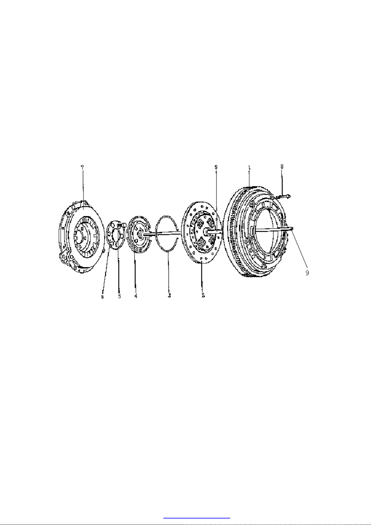
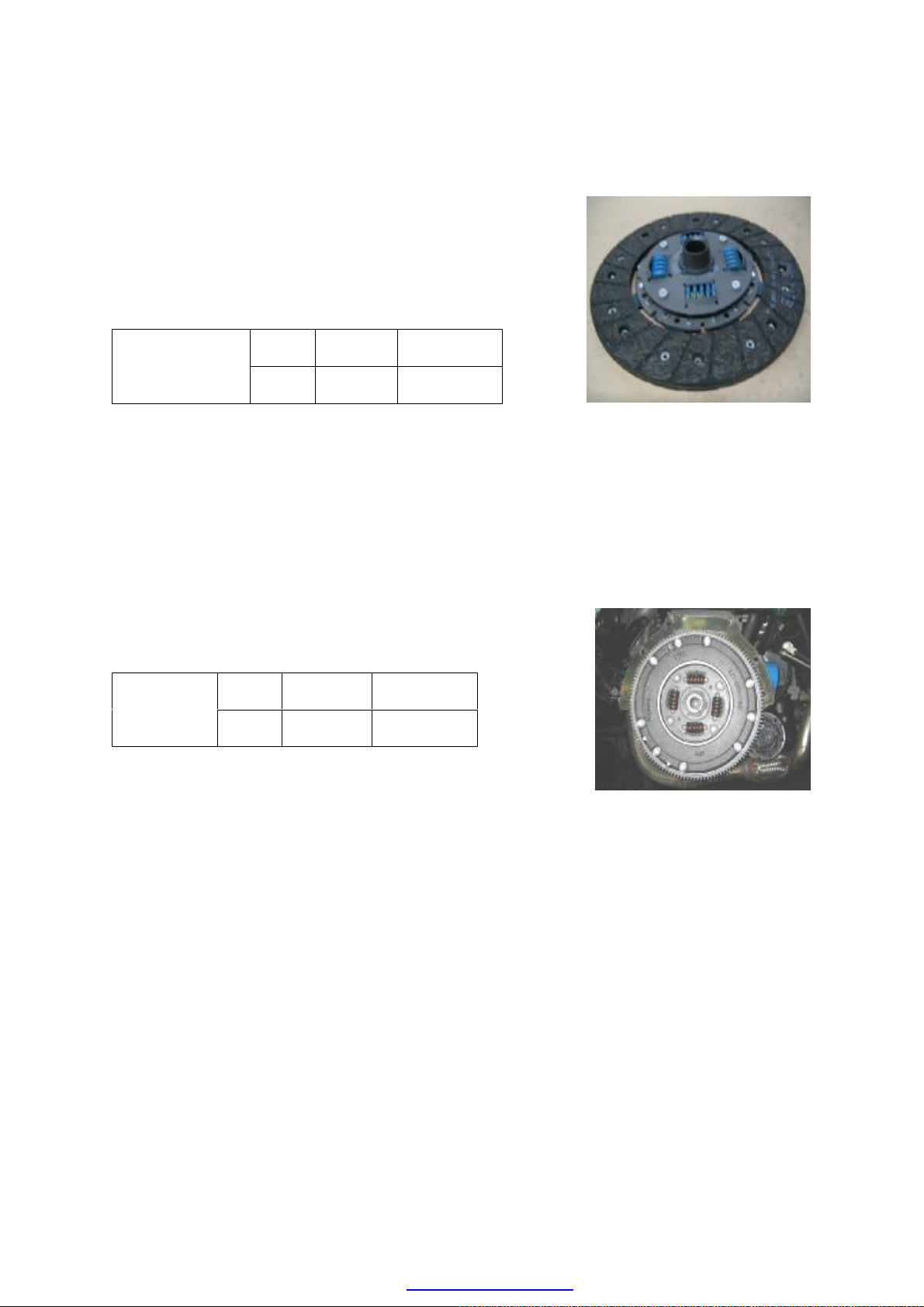
·As picture below, the clutch is dry diaphragm with single leaf. It consists of clutch driven
disk (2), release disk (4), intermediate disk (6), pressure plate (7) and flywheel (1).
·There are diaphragm springs in the pressure plate (7), which are fixed in the crankshaft by
intermediate disk (6) and bolt (5). Driven disk (2) is pressed on the flywheel (1) by
pressure plate (7), and bolt (8) is used to fix pressure plate (7) and flywheel (1) together;
the clutch pusher (9) is used to push separator disk (4) and then the separator disk (4) to
push the small end of diaphragm springs on pressure plate (7).
1.Flywheel 2.Driven Disk 3.Snap Ring 4.Release Disk 5.Bolt(M10)(110±5N.m)
6.Intermediate Disk 7.Pressure Plate 8.Bolt (23~25N.m) 9.Clutch Pusher
OPERATING PRINCIPLE OF CLUTCH
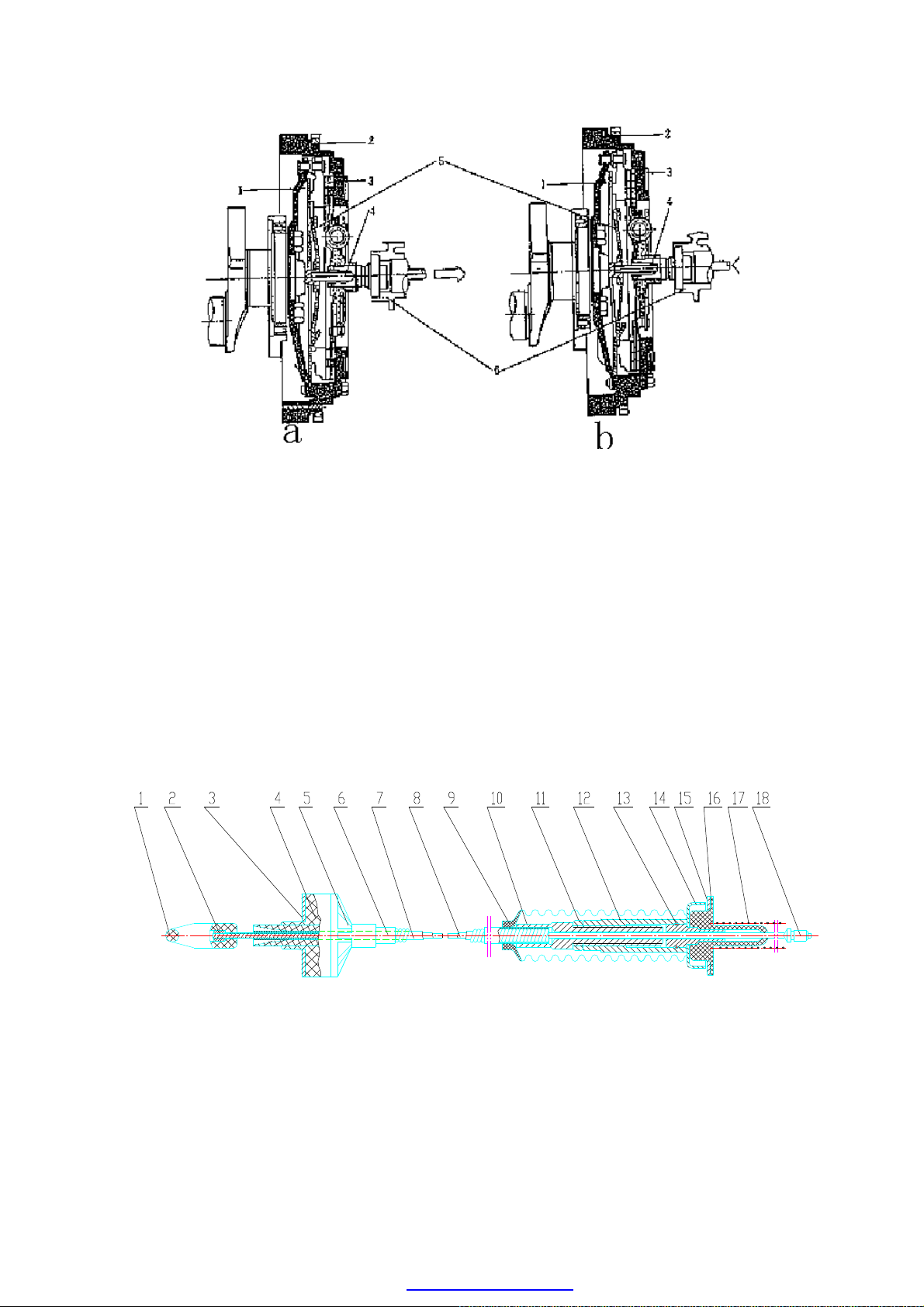
·As picture below, Picture a presents the connection status of clutch. When clutch pedal is
not treaded, the driven disk (3) is pressed on flywheel (2) by diaphragm spring (1). Driven
disk (3) and flywheel (2) are revolving synchronously, and the torque is transmitted to the
transmission-axle (6) by Separator disk (5) through driven disk (3).
·Picture b presents the disconnection state of clutch. When the clutch is treaded, pusher (4)
pushes separator disk (5) which presses the small end of diaphragm spring (1) to move the
big end of diaphragm spring (1) away from driven disk (3), so the pressure is disengaged
between driven disk (3) and flywheel (2) and the clearance is generated to cut off the
motive power of engine and pass the transmission.
F-2
PDF created with pdfFactory Pro trial version www.pdffactory.com
Page 3
in 6.Jacket
st Cover 10.Adjust Rod 11.Jam Nut 12.Adjust Bushing
a. Clutch Connection State b. Clutch Disconnection State
1.Diaphragm Spring 2.Flywheel 3.Driven Disk 4.Pusher
5.Seperator Disk 6.Transmission Axle
CLUTCH CABLE ASSEMBLY STRUCTURE
1.Clip 2.Cable Latch 3.Washer 4.Cable Cushion 5.Jacket Tie-
7.Inner Pipe 8.Cable 9.Du
13.Clip Ring 14.Retainer 15.Washer 16.Rubber Cushion 17.Gasket 18. Butt End
F-3
PDF created with pdfFactory Pro trial version www.pdffactory.com
Page 4

ASSEMBLY AND ADJUSTMENT OF CLUTCH CABLE
estern
Move direction of release
disk after driven disk wear
When driven disk wear down,
unscrew the nuts and adjust the
2~3mm free
travel
·Put dust cap up and screw jam nut (11) and
adjustment bushing (12) to the upper end
(make the adjustment travel L minimum)
so as to facilitate the assembly of clutch
cable.
·Coat a little lubricant on the assembly
fitting surface of clutch cable.
·Put clip (1) across the guiding cylinder of
clutch pedal on the front brattice to
connect the clutch pedal. Make sure that
washer (3) and end face of guiding
cylinder of clutch pedal are spliced.
·Make butt end (18) fixed by bracket after
across the slot in release arm of
transmission and rubber cushion through
the upper face of transmission.
·After the assembly, uplift the segregation
arm of transmission by hand and adjust the
adjustment bushing (12) down at the same
time, so the 2~3mm clearance for
segregation arm of transmission is
available; then tread the clutch pedal for 10
times to ensure the fitness of assembly and
readjust the adjustment bushing to
guarantee that the 2~3mm clearance for
segregation arm of transmission is
available (Remarks:For new clutch, the
adjustment travel L of driven disk cable
shall not be less than 18mm. See Pic.2).
·Carry out the driving examination for the
whole automobile. Clutch and gear shifting
operation shall be normal.
·Screw jam nut (11) down to close with
adjustment bushing (12), and then put
down dust cover (9).
L (adjustment travel)
Jam nut
Adjust
bushing
down
bushing to a proper position
Rubber cushion
Bracket
Transmission
release pusher
Picture 2 Sketch Map of W
Clutch Adjustment
F-4
PDF created with pdfFactory Pro trial version www.pdffactory.com
Page 5
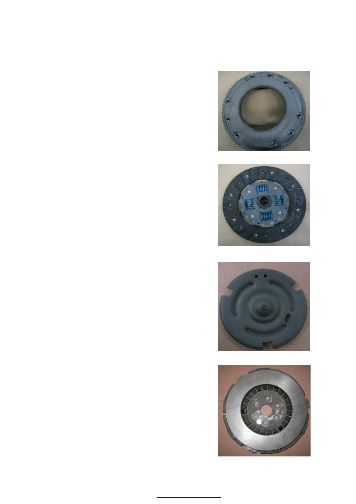
CLUTCH DISASSEMBLY
·Disassemble the transmission.
·Unscrew 9 fixed bolts in flywheel
cornerwise and dismount the flywheel.
·Remove clutch plate.
·Pry out snap ring of release disk by
screwdriver and remove the release disk.
·Unscrew 6 connection bolts in clutch
pressure plate and output end of
crankshaft, and remove the clutch pressure
plate.
F-5
PDF created with pdfFactory Pro trial version www.pdffactory.com
Page 6
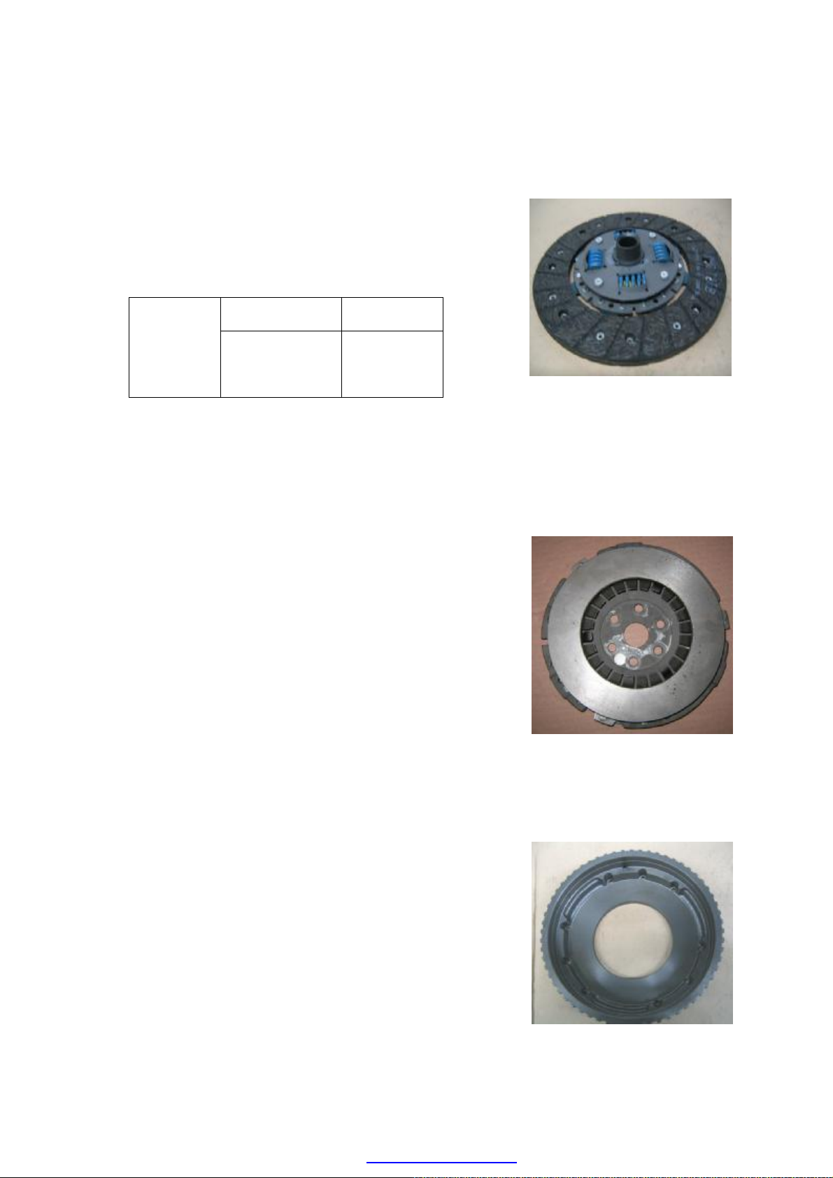
CLUTCH OVERHAUL
· Clutch friction disk: measure the dent depth of
rivet head, i.e. the distance between the rivet head
and the friction disk surface. In case it is found that
the depth reaches the using limit for any hole, the
friction disk shall be changed.
Standard value Maintenance
Rivet head
1.5mm
0.5mm
Dent depth
0.06in
0.02in
·Measure the clutch disc runout using a dial indicator.
If the runout is excessive, replace the clutch disc.
Runout 0.8mm max
Clutch pressure plate:
·Examine whether the diaphragm spring has
abnormal wear or damage.
·Examine whether the pressure plate has wear or hot
point.
·In case of any abnormality, the pressure plate shall
be changed. The pressure plate shall not be
disassembled into two parts: diaphragm spring and
pressure plate.
·Measure the clutch pressure plate runout using a dial
indicator. If the runout is excessive, replace the
clutch disc.
Runout 0.25mm max
Flywheel:
·Examine whether the connection surface of friction
disk exists abnormal wear or hot point; the change
or maintenance shall be conducted if necessary.
·Measure the flatness of the flywheel with a straight
edge and a feeler gauge. If not as specified, replace
the clutch cover.
Maximum clearance 0.05mm
Service limit 0.15mm
F-6
PDF created with pdfFactory Pro trial version www.pdffactory.com
Page 7
CLUTCH INSTALLATION
Before the assembly, flywheel surfaces and pressure
plate shall be clear and dry.
——Assemble the pressure plate on the crankshaft
and screw up bolts in accordance with
prescribed moment.
Pressure plate
assembly bolt
Torque
—— Assemble release disk and fit on snap ring.
—— Assemble clutch disk.
—— Assemble flywheel.
——Screw up flywheel bolt uniformly according to
the diagonal line.
——Coat a thin layer of grease on the input axle
and then assemble the transmission with
engine.
N•m Kg-m 1b-ft
57-65 5.7-6.5 41.5-47.0
Flywheel
bolt
Torque
Remarks:
When put the input axle of transmission into the
clutch friction disk, the flywheel shall be revolved
until the input axle of transmission and spline
meshed.
N•m Kg-m 1b-ft
18-28 1.8-2.8 13.5-20.0
F-7
PDF created with pdfFactory Pro trial version www.pdffactory.com
Page 8

Trouble
symptom
Slip of clutch
Uncompleted
segregation of
clutch
Vibration of
clutch
Clutch noise
Non-separation of
clutch
TROUBLE DIAGNOSIS
Cause Treatment method
•Free travel (free play) of clutch pedal is wrong.
•Abrasion or oil stain for clutch friction disk.
•Distortion for friction disk 、 pressure plate or
flywheel surface.
•Diaphragm springs become weaker.
•Free travel of clutch pedal is wrong.
•Diaphragm springs become weaker or abrasion for
stabber fingertip.
•Rust for input axle spline.
•Mutilation or abrasion for input axle spline of
transmission.
•Excessive nodding action for clutch friction disk
assembly.
•Abrasion or oil stain for clutch friction disk.
•Brighten of clutch friction disk (to become
glassiness).
•Oil stain for clutch friction disk.
•Bad skid of segregation bearing on the bearing
sleeve of transmission.
•Shimmy of clutch friction disk assembly or bad
connection of friction disk.
•Vibration reduction torsion springs of clutch
friction disk assembly become weaker.
•Loose of rivet of clutch friction disk.
•Distortion of pressure plate or flywheel surface.
•Loose of the binding bolt of flywheel or loose of
binding bolt of pressure plate assembly.
•Abrasion or mutilation for segregation bearing.
•Abrasion for front bearing of input axle.
•Abnormal noise for clutch friction disk.
•Crack for clutch friction disk.
•Abnormal noise for pressure plate and diaphragm
spring.
•Clutch friction disk has fat liquor.
•Serious wear of clutch friction disk.
•Rivet head is displayed in surface of disk.
•Torsion springs become weaker
Adjust free travel
Change friction disk
Change frication disk,
pressure plate or flywheel
Change clutch pressure plate
Adjust free travel
Change pressure plate
Lubricate
Change the input shaft
Change friction disk
Change friction disk
Repair or change friction
disk
Change friction disk
Lubricate
Change friction disk
Change friction disk
Change friction disk
Change pressure plate or
flywheel
Screw down
Change segregation bearing
Change input shaft bearing
Change friction disk
Change friction disk
Change pressure plate
Change friction disk
Change friction disk
Change friction disk
Change friction disk
F-8
PDF created with pdfFactory Pro trial version www.pdffactory.com
Page 9

COOLING SYSTEM
DESCRIPTION OF COOLING SYSTEM … … …… …… … …… …… … …… …C-2
COMPONENTS OF 480 ENGINE COOLING SYSTEM … … ……………………C-2
WORKING PRINCIPLE OF COOLING SYSTEM … … …… …… … …………C-2
PARAMETERS OF COOLING SYSTEM … … …… …… … …… …… … …… C-3
ENGINE COOLANT … … …… …… … …… …… … …… …… … …………… …C-3
COOLANT DISCHARGE … … …… …… … …… …… … ………………………C-3
COOLING SYSTEM CLEANING … … …… …… … …… …… … ……… …C-3
COOLANT FILLING … … …… …… … …… …… … …… …… … ……………C-4
COOLING SYSTEM CHECKUP …… …… ……… ……… ……… …… …… …C-5
COOLING SYSTEM MAINTENANCE WARNING … … …… …… … ……… …C-5
WARNING … … ………… ………… ………… ………… …… …… … …… …C-5
WATER PUMP … … …… …… … …… …… … …… … … … ………………………C-6
STRUCTURE … … …… …… … …… …… … …… …… … …… …… … …C-6
DISASSEMBLY/ASSEMBLY … … …… …… … …… …… … …… …… … …C-6
THERMOSTAT … … …… …… … …… …… … …… …… … …… …… … …… …C-7
DISASSEMBLY/ASSEMBLY … … …… …… … …… …… … …… …… … …C-7
WATER TEMPERATURE SENSOR … … …… …… … …… …… … ………… …C-9
DISASSEMBLY/ASSEMBLY … … …… …… … …… …… … …… …… … …C-9
CHECKING … … …… …… … …… …… … …… …… … …… …… … …… C-9
COOLING FAN … … …… …… … …… …… … …… …… … …… …… … …… C-9
DISASSEMBLY/ASSEMBLY … … …… …… … …… …… … …… …… … …C-9
GUIDELINE FOR DISASSEMBLY … … …… …… … …… …… … ……… …C-10
EXPANSION RESERVOIR … … …… …… … …… …… … …… …… … …… …C-11
DISASSEMBLY/ASSEMBLY … … …… …… … …… …… … …… …… … …C-11
ASSEMBLY OF RADIATOR …… …… …… … ……… …… … …… …… … …… C-12
DISASSEMBLY/ASSEMBLY … … …… …… … …… …… … …… …… … …C-12
C-1
PDF created with pdfFactory Pro trial version www.pdffactory.com
Page 10

COOLING SYSTEM
Hose
Thermostat Chassis and
Hose Hose Hose Hose
Radiato
DESCRIPTION OF COOLING SYSTEM
COMPONENTS OF 480 ENGINE COOLING SYSTEM
Engine cooling system is used to cool engine to
prevent the engine from overheating, ensuring the
normal operation of engine. It is composed of the
timing belt-driven water pump, transverse radiator,
water tank, water pipe, thermostat, temperature control
switch of electrically-driven fan and water temperature
sensor.
WORKING PRINCIPLE OF COOLING SYSTEM
When the temperature of engine coolant is
relatively low, the thermostat shall turn it off, and the
coolant shall circulate and flow among the cylinder
block, water pump and warm air exchanger. This kind
of circulation is called small circulation.
When the temperature of engine coolant is
relatively high, the thermostat shall turn it on, the
coolant shall flow into the radiator, the electrically
-driven fan shall operate to lower down the temperature
of coolant. And then the coolant shall flow back to the
engine cylinder block. This kind of circulation is called
big circulation. As the big circulation operates, the
small circulation shall also play its role.
Warm Air/Heat Exchanger
Engine
Water Pump Inlet
Water Temperature Sensor
Cooling Water Pipe Assembly
Hose Assembly
Electrically-Driven Fan
Pressure Cap
Thermostat Assembly
Hose Assembly
Thermo-Switch
Expansion Tank
As the engine works under normal work
temperature the engine coolant shall expand. Under this
circumstance, the overflow valve installed on the
thermostat chassis shall turn it on, the coolant shall
flow into the expansion water tank through the
overflow pipe; and as the system cools down, the
coolant shall flow back to the water pump inlet from
the expansion reservoir.
The operation of electrically-driven fan is
controlled by the thermo-switch installed on the right
water chamber of radiator. When the contact points of
thermo-switch meet together, the electrically-driven fan
shall run. The water temperature sensor is fitted on the
back of cylinder head lying at the side of exhaust pipe.
C-2
PDF created with pdfFactory Pro trial version www.pdffactory.com
Page 11
PARAMETER OF COOLING SYSTEM
Cooling system Parameter
Total system capacity(L) 8
Coolant capacity
Fan
Water pump
Radiator
Thermostat
Thermo-switch
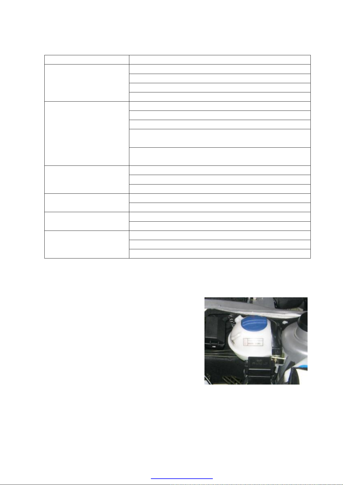
Coolant Discharge:
――To demount the pressure cap of expansion
reservoir;
Engine capacity(L) 3.3
Radiator capacity(L) 2.1
Expansion reservoir capacity(L) 0.4
Diameter: 280mm
Number of blades: 6
Operating voltage: 9-15V
Rotating speed Ι gear: high-speed engine 2000±200
Rotating speed II gear: high-speed engine 2800±200
Diameter of impeller: ф72mm
Transmission rate: 1.053:1
Opening pressure of the pressure cap: 160kPa
Front face area: 0.202m²
Heat abstraction area: 8.93m²
Opening temperature: 85º-89º
Full opening temperature: 99º-102º
Switch-on temperature gear95 Cº gear 102 CºⅠⅡ
Switch-off temperature gear≤84 Cº gear≤91 CºⅠⅡ
Operating voltage: 12V
ENGINE COOLANT
low-speed engine 1800±200
low-speed engine 2600±200
――To install a vessel under the radiator, demount
the radiator outlet hose under the radiator and
discharge the coolant.
Cooling System Cleaning:
――To discharge coolant, mount the radiator outlet
hose;
――To inject clean water up to the position of the
largest water surface of the expansion reservoir
from the expansion reservoir filler, and then close
the pressure cap;
――To start up engine to make it operate at idle speed,
C-3
PDF created with pdfFactory Pro trial version www.pdffactory.com
Page 12
preheat up to normal operating temperature, shut
――To check whether the pipeline is well connected
e cap; fill up coolant into the
expansion reservoir filler slowly. Since the
expansion reservoir is at the highest position in the
herefore, as the coolant level
rises, the air in the system shall be discharged into
and shall be discharged out
of the expansion reservoir by injecting coolant
――To continuously inject coolant up to the highest
nd then close the filler to prevent
――To start up the engine to make it operate at idle
speed and preheat up to normal operating
ns to run,
observe water thermometer and check if the engine
is at overheating condition. If the coolant level in
down and cool down;
――To discharge coolant;
――To repeat the abovC-mentioned steps until the
discharged water is the same as the clean water;
――To clean the cooling system according to the
following methods if the coolant is not correctly
used and replaced to meet the requirements in the
former utilization:
a. To discharge coolant;
b. To demount the radiator inlet hose, insert the main
water hose into the radiator filler until the outlet
water becomes clean;
c. In order to flush out the engine, you should connect
the main water hose with the water outlet of the
thermostat to clean the engine until the discharged
water flowing from the water pump inlet becomes
clean;
d. To repeat cleaning operations if the radiator is very
dirty, and connect the main water hose with the
radiator water outlet until the water flowing from
the radiator water outlet becomes clean.
Coolant Filling:
and fastened before injecting coolant;
――To open the pressur
cooling system. T
the expansion reservoir
slowly.
coolant level. A
coolant from spilling.
temperature. And until the fan begi
C-4
PDF created with pdfFactory Pro trial version www.pdffactory.com
Page 13

the expansion reservoir descends quickly, coolant
should be injected up to the highest position to cut
down the air circulation in the system.
if
――To open the pressure cap to check the coolant level, and
vel, start up the engine and
preheat it. Put the engine under idle speed
circumstance until the cooling fan runs, and check
if coolant leakage exists at various pipe joints. Shut
down the engine and wait for engine cooling. And
vel in the expansion
――To try best to prevent the coolant spilling from
――To shut the engine down to have it fully cooled(
possible, leave the engine alone for one night.);
inject coolant up to the highest position.
Cooling System Checkup:
――To check the coolant le
then check if the coolant le
reservoir is at normal condition.
scalding operator during checkup.
――To timely check if water flows into the engine oil
pan (the lubricating oil shall become milk white
after water flows) when no pipe leakage is found
and the expansion reservoir is short of coolant, and
timely stop water from flowing in when finding it.
COOLING SYSTEM MAINTENANCE WARNING
Warning:
·To try best not to move radiator cap or loose the radiator discharging plug when the engine
is under operation or the engine and radiator are at a very high temperature. Scorching
coolant may spill out, hurting the people and damaging the engine and cooling system.
·To shut down the engine until it cools down, and then carefully demount the radiator cap.
Meanwhile, wrap a large thick cloth onto the radiator cap, rotate it slowly to the position
of the first clip along the counter-clockwise direction and then release the pressure slowly.
·To use a cloth to push down the radiator cap, rotate and remove the radiator cap after the
operator ensures all the intensity of pressure has been released.
C-5
PDF created with pdfFactory Pro trial version www.pdffactory.com
Page 14
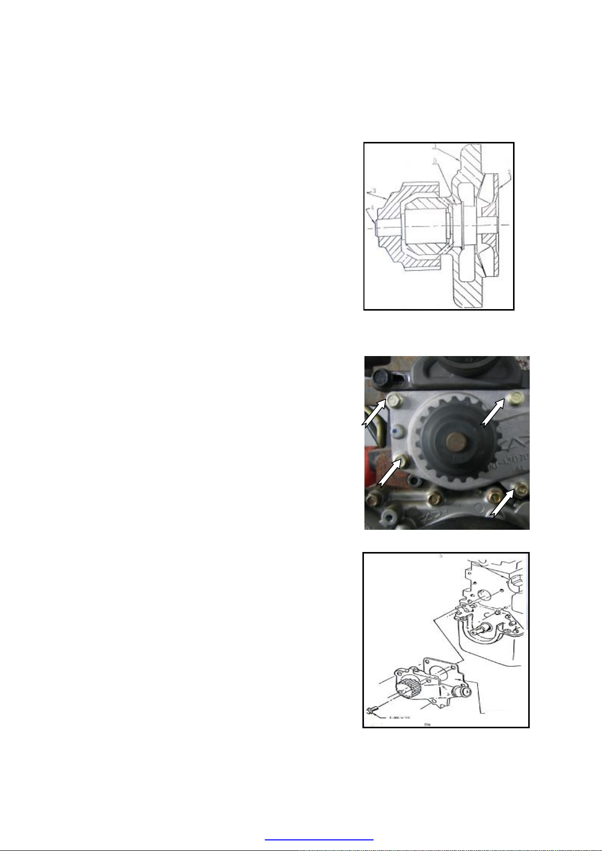
WATER PUMP
Structure:
To discharge engine coolant (refer to the coolant
4 bolts out of the front side of
To install the water pump assembly in the cylinder
block and screw up 4 fixing bolts by hand, and
The water pump impeller installed in the cylinder
Note: Because water pump assembly can not be
seal ring or bearing
Tightening Torque
Gasket
1—Water pump housing
2—Water pump impeller
3—Water pump gear
4—Water pump shaft bearing
5—Water pump seal (ceramics-lead)
Disassembly:
——To disconnect the negative terminal of battery;
——
discharge process);
——To disconnect poly V-belt and power pump belt;
——To demount timing shield;
——To unscrew and take
cylinder block.
——To demount the water pump assembly;
——To demount the water pump gasket.
Assembly:
——To install the new gasket on the water pump;
——
then screw up to 7.0—10.0Nm;
——
block should be able to rotate freely;
——To refill engine coolant;
——To check leakage occurrences of engine coolant.
repaired, it should be replaced when
is worn and torn.
C-6
PDF created with pdfFactory Pro trial version www.pdffactory.com
Page 15
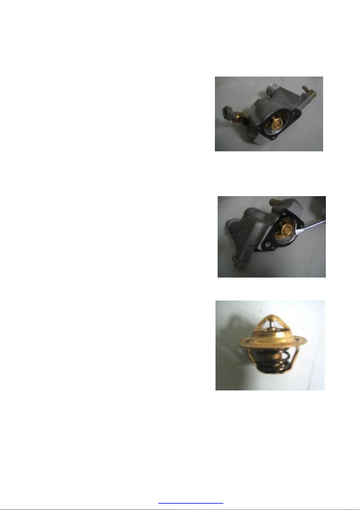
THERMOSTAT
To unscrew 3 M6×40 bolts and then demount the
To demount thermostat chassis and thermostat
To pry out the spring clamps by using chisel or
Disassembly:
——
bolts;
——
assembly.
——
screwdriver.
——To take the thermostat out;
——To clean up the thermostat;
C-7
PDF created with pdfFactory Pro trial version www.pdffactory.com
Page 16
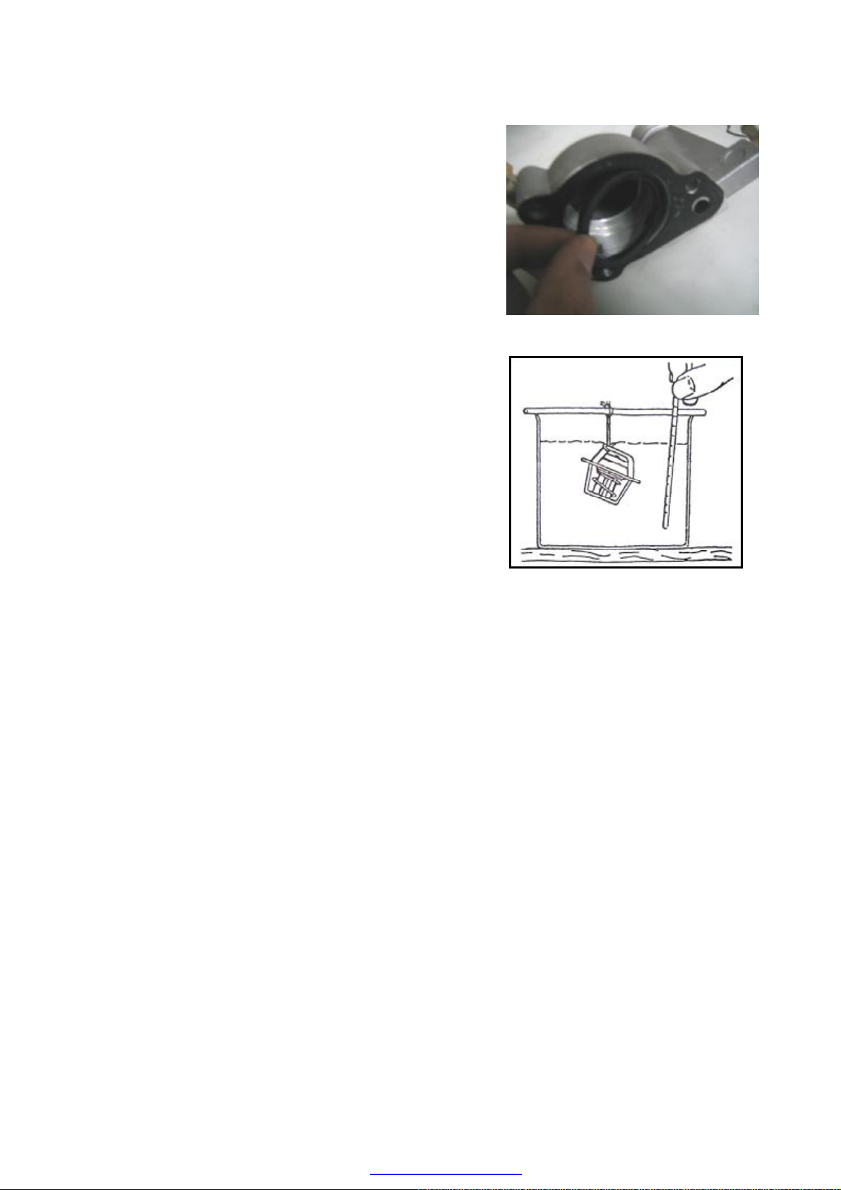
——To take the seal ring
out, and replace it if it being
To demount the gasket from the thermostat chassis.
To measure the thermostat opening temperature
worn and torn.
——
(To replace with new gasket if it is worn and
torn, and allow no repeated use.)
——
under hot water.
Assembly:
——To clamp the thermostat and then put the gasket
into the thermostat aperture.
——To install thermostat (the side with spring facing
outward).
——To embed spring clamp to ensure the clip within
the thermostat chassis slot;
——To mount new gasket onto thermostat chassis;
——To mount the thermostat chassis and thermostat
assembly into the aperture at the rear side of engine
cylinder head, and screw up the bolt by hand to
9—12N.m.
C-8
PDF created with pdfFactory Pro trial version www.pdffactory.com
Page 17
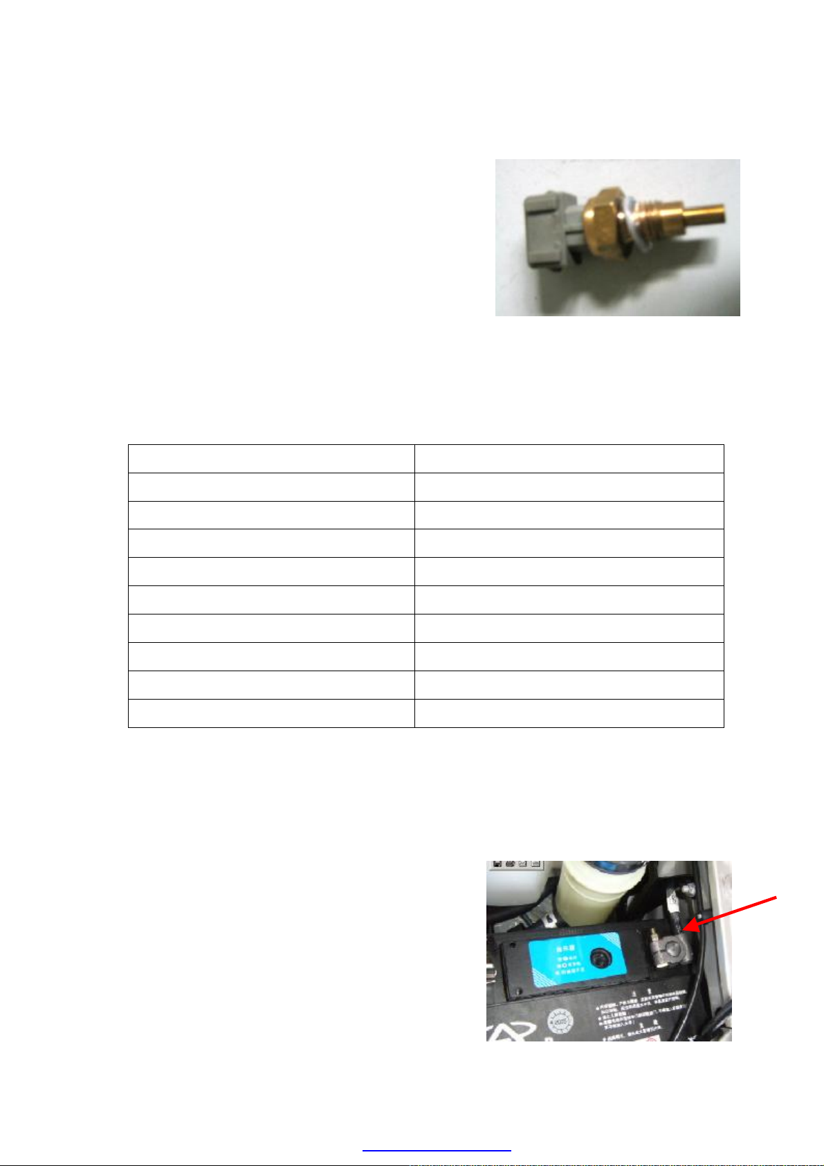
WATER TEMPERATURE SENSOR
Disassembly:
——To demount water temperature sensor (at the
exhaust pipe flank and under the lifting eye).
Assembly:
——To apply Letai 243 glue on the screw thread,
screw up the bolt to 7.0—10.0Nm before
installation.
Checking:
Water temperature sensor is a negative temperature coefficient sensor, which is composed of
a thermal resistor. The resistance value of the resistor shall decrease as the engine temperature
rises. The variation is detailed in the following table:
Temperature (°C) Resistance Value (Ω)
-20 29,125
-10 16,660
0 9,790
+20 3,748
+25 3,000
+60 747
+80 377
+100 204
+120 117
COOLING FAN
Disassembly:
——To disconnect the negative terminal of battery;
C-9
PDF created with pdfFactory Pro trial version www.pdffactory.com
Page 18
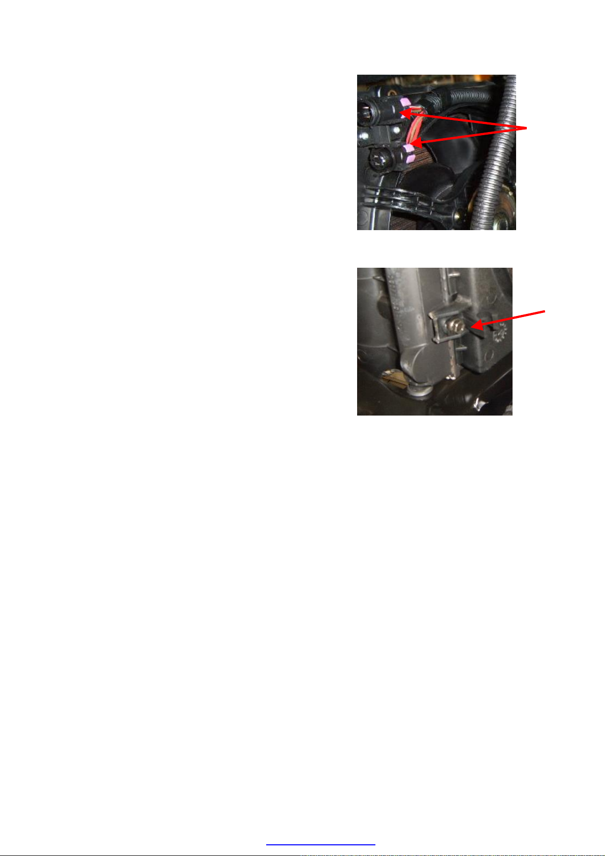
——To demount the matching plug of the cooling fan.
tapping screw from
p the engine and check if the cooling fan
During the disassembly process, you should pay
more attention not to pull A/C pipe to a large extent,
——To remove the fastening self-
the cooling fan.
——To take the cooling fan out.
Assembly:
——To assemble the cooling fan according to the
disassembly order (the tightening torque of
self-tapping screw is 1.8~2.2Nm)
——To start u
is under normal operation.
Guideline For Disassembly:
——
otherwise the A/C pipe shall crack and deform.
C-10
PDF created with pdfFactory Pro trial version www.pdffactory.com
Page 19
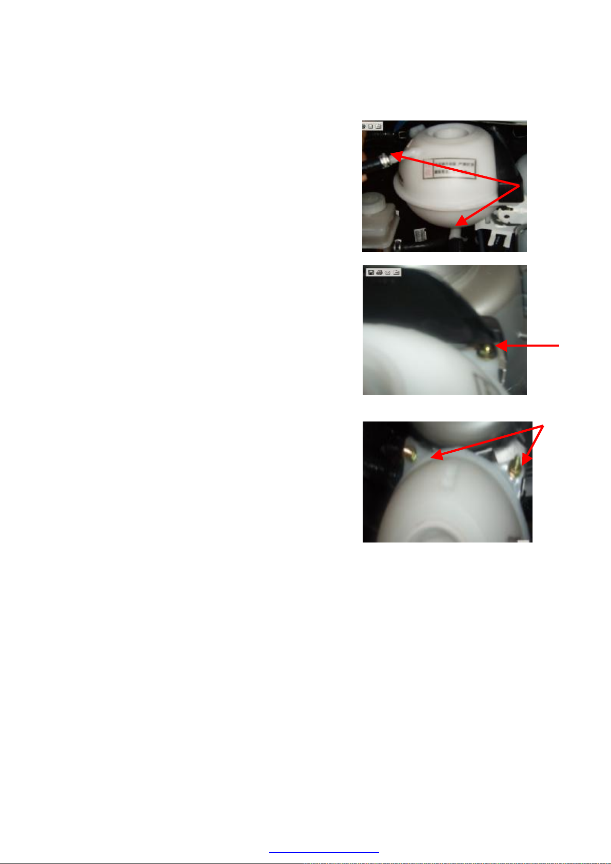
EXPANSION RESERVOIR
Disassembly:
——To demount the water pipe connecting with the
expansion reservoir.
——To pry out the protecting hood of expansion
reservoir by using a screw drive.
——To demount the fastening bolts of the expansion
reservoir by using M10 sleeve.
——To pull out the plug of liquid level sensor.
——To take the expansion reservoir out.
C-11
PDF created with pdfFactory Pro trial version www.pdffactory.com
Page 20
To demount the left and right wind boards by M10
Assembly:
——To assemble the expansion reservoir according to
the order opposite to the disassembly order(the
tightening torque of self-tapping screw is
4.0~5.0Nm).
——To refill coolant.
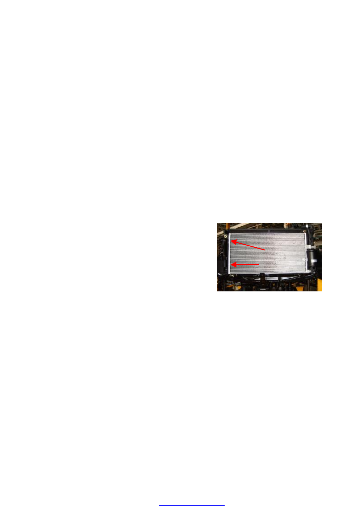
ASSEMBLY OF RADIATOR
Disassembly:
——To discharge coolant (refer to the coolant discharge
process)
——To demount the cooling fan (refer to the
disassembly process of the cooling fan).
——
sleeve.
——To take out the radiator.
C-12
PDF created with pdfFactory Pro trial version www.pdffactory.com
Page 21
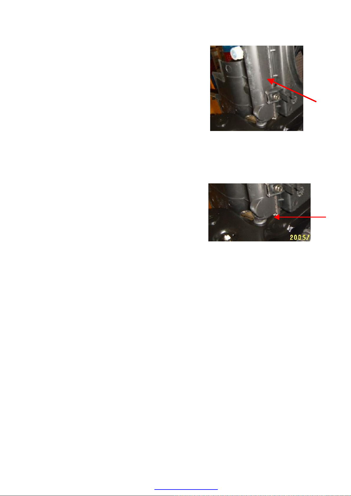
——To take out the radiator
Assembly:
——To assemble the radiator according to the order
opposite of the disassembly order.
——To install the 2 wind boards onto the radiator by
using self-tapping screws with their tightening
torque of 6~7Nm.
——To install the radiator onto the front transom and
put it straightly towards the positioning hole.
——To install the left and right tensioned plates of the
radiator, and tighten the bolts of the plates with
tightening torque of 5±1Nm.
C-13
PDF created with pdfFactory Pro trial version www.pdffactory.com
Page 22

ENGINE ELECTRONIC SYSTEM
INPUT / OUTPUT COMPONENTS OF CONTROL SYSTEM … …… … … … …E-2
WORKING MODULE TABLE OF FUEL INJECTION / IGNITION SYSTEM …E-3
WORKING PRINCIPLE … …… … … … …… …… … … … …… …… … …E-4
ELECTRICAL CONTROL UNIT …… …… … … … …… …… … …………E-5
WORKING PRINCIPLE OF ELECTRONIC FUEL INJECTION CONTROL AND
ACTUATORS …………………………………………………………………………E-7
BASIC PRINCIPLE OF MALFUNCTION DIAGNOSIS FOR ELECTRONIC FUEL
INJECTION SYSTEM ………………………………………………………………E-21
DETAILED TABLE OF MALFUNTION DIAGNOSTIC CODE …………………E-24
PROCEDURES FOR FAULT DIAGNOSIS ACCORDING TO THE SYMPTOMS OF
THE ENGINE …… …… …… … …… …… …… …… …… …… …… ……E-62
SAFETY PRECAUTIONS OF SYSTEM MAINTENANCE ………………………E-88
SAFETY PRE CAUT IONS IN DI AGOSIS AND M AINTENANCE OF T HE
GASOLINE INJECTION ELECTRONIC CONTROL SYSTEM …………………E-88
SAFETY MEASURES ……………………………………………………………E-89
E-1
PDF created with pdfFactory Pro trial version www.pdffactory.com
Page 23

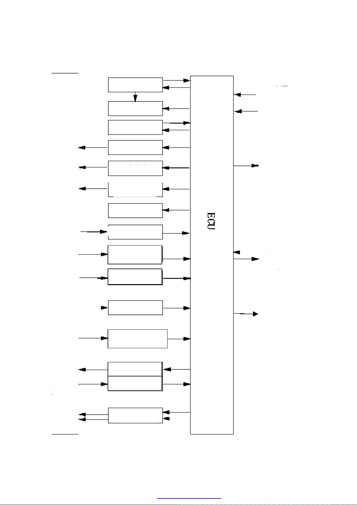
INPUT / OUTPUT COMPONENTS OF CONTROL SYSTEM
19
18
Diagnostic
connector
1 Engine ECU 11 Fuel injector
2 Air pressure / temperature sensor 12 Oxygen sensor (heater)
3 Engine speed sensor for top dead center 13 Fuel pump
4 Throttle valve position sensor 14 Carbon canister solenoid valve
5 Knock sensor 15 Two step speed fan controller
6 Coolant temperature sensor 16 Compressor relay control
7
Oxygen sensor (λ signal)
17 Idling speed step motor
8 Air condition request 18 Diagnostic connection
9 Ignition coil and spark plugs 19 Relay
10 Instrument panel
E-2
PDF created with pdfFactory Pro trial version www.pdffactory.com
Page 24
WORKING MODULE TABLE FOR FUEL INJECTION / IGNITION
Fuel pump
A/C relay
Fuel injector
Carbon canister
Throttle valve
position sensor
Air pressure /
Power supply
Cooling temperature
SYSTEM
Power supply relay
(Power supply +12V)
Power supply
(15/54)
Idling speed step motor
Malfunction
indicator
Ignition coil
ENGINE
Engine
solenoid valve
Coolant temperature sensor
Line K
temperature sensor
Knock sensor
·
overheat alarm light
·Decoder alarm light
TDC/rotate speed sensor
Oxygen sensor heater
Heated Oxygen sensor heater
·R.P.M. meter
Fan relay
E-3
PDF created with pdfFactory Pro trial version www.pdffactory.com
Page 25

WORKING PRINCIPLE
This system is capable of controlling the actual tested air-fuel ratio under all engine speeds to
stay close to the equivalent proportion of the chemical reaction, so as to protect the catalyst
package and subsequently reduce the discharge of pollution. The oxygen sensor analyses the
oxygen content of the discharge gas using real-time principle and makes it possible for the
ECU to control the amount of injecting fuel to correct the air-fuel ratio. The fuel with a
pressure of about 3.5 bars is directly injected into the air intake manifold near the throttle
valve.
The fuel injectors of all cylinders are utilizing a sequential phase angle control method
according to the intake sequence and the opening time of the air intake valves; the injection
destinations are stored in the ECU map, and can vary autonomously according to the engine
speeds and intake air pressures. The application of sensors in the system is a basic strategy
used to correct the engine under all operating conditions. The system is implementing an
induction type of electrical discharge ignition, where the power source module in the ECU
controls the ignition timing. The ignition advance angle is calculated according to the engine
compression ratio and intake air volume. The idling speed is maintained at stable condition
through controlling the opening of the branch-connection pipe by a step motor and also
through the changing of the ignition points.
Other than capable of obtaining the input signals and controlling the output components, the
system has also equipped with various other functions. These functions include the following:
- When self-diagnose that the sensor is faulty, adopt the restoration strategic control.
- Restoration of the self-regulating mixed concentration engine and variances in spare parts.
- Exchange data with the diagnostic tester.
The idling speed of the engine and the amount of CO in the air discharged must not be
manually adjusted.
E-4
PDF created with pdfFactory Pro trial version www.pdffactory.com
Page 26

ELECTRONIC CONTROL UNIT
The ECU is located on the left of engine firewall. The ECU handles various signals from the
sensors and controls the actuator so as to achieve the best possible operating condition. Many
extra functions are added as compared with the previous model. While by the usage of a
custom-made circuit board that can achieve many special functions, the integrated functions
are enhanced so that the structure has considerably reduced in size and become much more
compact.
The hard wares in the ECU are as follows:
-16 bit CPU single chip
- 8KB RAM (2KB IRAM + 6KB ERAM)
- 2MB FLASH EPROM (12V programming voltage)
- 2KB SERIAL EEPROM
- 16 CHANNELS 10 MODULES/NO. (A/D) CONVERTER
- 4PWM OUTPUT
- CAN MODULE (CAN2.0B)
The ECU software structure is divided into two parts for data processing:
-The “Application” part obtained the measurement of engineering parameter through sensors
to calculate the control parameters of the fuel injectors, ignition coils and idling speed step
motor for controlling the engine starting.
-The “Basic” part is collecting the data from the sensors and converts it into engineering data.
After that it controls the actuator through the calculated parameter generated by the
“application” software, and manages the self-diagnostic programs of the various sensors and
actuators. In addition, it can also communicate with the externally connected diagnostic
tester through the use of “K” serial cable.
The operating system is capable of ensuring the accurate management of the matters related
with time (such as the management of definite and delay timing) and angles (related to the
engine rotation sequence). This type of management is integrated in the software and
calculated according to the precise priority to ensure the optimization management of the
engine even at its high-speed condition. This type of “modular structure” design allows the
possibility of achieving all kinds of flexibility control and in the mean time not tampering the
overall characteristic of the system.
The following data are transmitted into the ECU:
- Battery voltage
- Absolute pressure sensor in the air intake manifold
- Top dead center
- Throttle valve opening angle position
- Air intake temperature
E-5
PDF created with pdfFactory Pro trial version www.pdffactory.com
Page 27

- Engine coolant temperature
- Air conditioning operation
- Signal from oxygen sensor
- Knock sensor for the accelerator meter on top of the engine crankshaft housing
The air intake efficiency is obtained by calculating through the processing of absolute
pressure, air intake temperature, engine speed, throttle valve position and other signals, and
help to determine the air intake quantity of the cylinder. The inbuilt power supply module in
the ECU is controlling the following functions:
- To control the injected fuel quantity through the control of opening timing of the fuel
injector
- Idling speed step motor
- Ignition coils of the 4 high voltage outputs
- Check valve for recirculation the gaseous fuel on top of the air intake manifold (carbon
canister)
- Temporary turnoff of the air condition compressor
- Dual speed cooling fan for the engine
- Overheating alarm light in the coolant of the engine
- Malfunction alarm light
Other than these major functions, ECU also controls:
- All the self-diagnostic strategy related to input sensors and output actuators
- Wrong signals restoration strategy works on basically effective input signals
E-6
PDF created with pdfFactory Pro trial version www.pdffactory.com
Page 28
WORKING PRINCIPLE OF ELECTRONIC FUEL INJECTION
Manif
old absolute
pressure and intake air
temperature sensor
CONTROL AND ACTUATORS
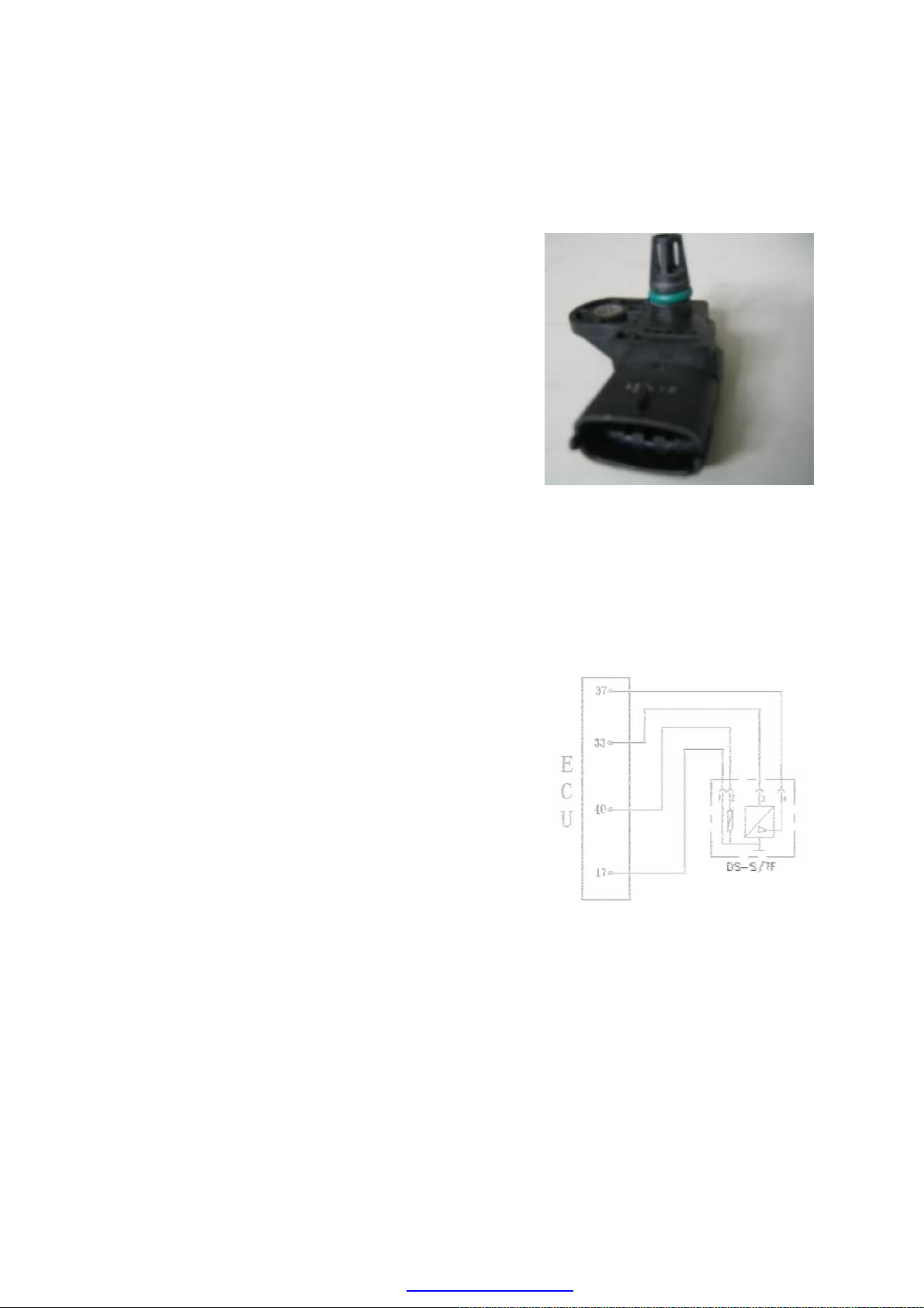
※ Intake Pressure and Intake Air Temperature
Sensor
Purpose: detects manifold absolute pressure from
0.1~0.2bar and intake air temperature, provides engine
with load information.
Composition and principle: this sensor is composed
of two different sensors (i.e. manifold absolute
pressure sensor and intake temperature sensor), and is
installed above pressurizer.
Pressure-sensitive element inside intake pressure
sensor detects pressure signal on intake manifold for
injection pulse width control of EFI system. This
sensor also serves as the substitute of load signal
sensor.
Intake air temperature sensing element is a resistor
of negative temperature coefficient (NTC), which is
similar to water temperature sensor with resistance
value decreasing with the increasing of intake air
temperature. And engine ECU monitors the variation
of intake air temperature via a comparison circuit
inside.
TMAP
Failure diagnosis: The electronic device next to
intake pressure sensor detects sensor circuit troubles
such as open circuit, short circuit and sensor damages,
etc. In case ECU detects any sensor output signal that
goes beyond output characteristic curve, the sensor is
diagnosed as failed by ECU. For example: when
intake pressure is higher than upper limit or lower than
lower limit, ECU detects sensor failure (in case that
intake pressure is lower than lower limit when starting,
ECU is able to recognize the starting condition), and
the engine fault indicating lamp goes on. Under this
condition the engine works in failure mode.
Installation: to be installed on pressurizer.
Circuit diagram of manifold absolute
pressure and intake air temperature sensor
Pins:
1# is grounded (connecting ECU 17#);
2# outputs temperature signal
(connecting ECU 40#);
3# connects with standard 5V power
source (connecting ECU 33#);
4# outputs pressure signal (connecting
ECU 37#).
E-7
PDF created with pdfFactory Pro trial version www.pdffactory.com
Page 29
Troubleshooting: mainly check if there is short circuit
1 Seal ring
5 Ca
sing
Failure diagnosis:
or open circuit on the connection between 4 lines on
sensor and ECU.
If there is short circuit, open circuit or grounding
between sensor wire harnesses.
Sectional view of intake pressure and
intake air temperature sensor
2Stainless steel bushing 6 Pressure bracket
3 PCB 7 Welded joint
4 Sensing element 8 Bonded joint
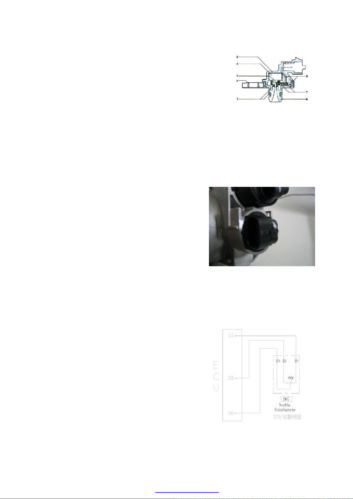
※Throttle Position Sensor
Purpose: this sensor is designed to provide ECU with
information of throttle angle. As per such information,
ECU obtains engine load information and operating
mode information (for instance: start-up, idle speed,
reverse, part load and full load) as well as acceleration
and deceleration information. This sensor is three-wire
style, and the throttle opening can be detected by ECU
via monitoring voltage variation.
Composition and principle: Consisting of two
compass sliding contact resistors and two sliding
contact arms, throttle position sensor is an angle
sensor that outputs linear signals. The axes of contact
arms are on the same axial line with throttle axis, with
5V power supply voltage US being applied to both
ends of each contact resistor. When throttle turns,
contact arms turn along with it and move on sliding
contact resisters, educing potential of contacts UP as
output voltage. This sensor is actually an angle
potentiometer.
Throttle Position Sensor
ECU monitors throttle angle, and
detects sensor failure when output signal exceeds
upper or lower limit, in which case engine will work in
failure mode, and fault indicating lamp will go on.
Installation: allowable tightening torque for fastening
screw is 1.5Nm-2.5Nm.
E-8
PDF created with pdfFactory Pro trial version www.pdffactory.com
Circuit diagram of throttle position sensor
Page 30
Pins:
1 sensor signal ground (ECU17#)
2 5V power (ECU32#)
3 sensor signal (ECU16#)
Troubleshooting: mainly check if there is short circuit
or open circuit on the connection between 3 lines on
sensor and ECU.
Check to see if there is short circuit, open circuit or
grounding between sensor wire harnesses.
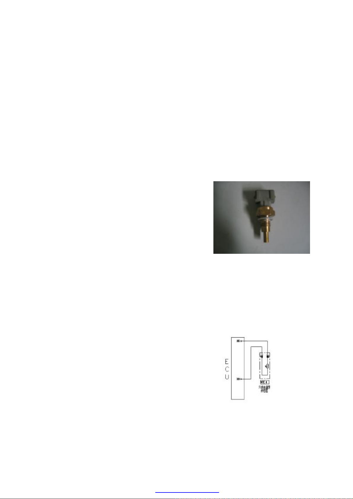
※Coolant Temperature Sensor TF-W
Purpose: this sensor is designed to provide coolant
temperature information. To provide engine ECU with
water temperature signal used for control of ignition
timing and fuel injection pulse width in startup, idle
speed and normal operation.
Composition and principle: this sensor is a
thermistor of negative temperature coefficient (NTC)
with resistance value decreasing with the increasing of
coolant temperature except linear relation. The said
thermistor is installed in a heat-conducting sleeve.
ECU monitors water temperature variation by
converting resistance value of thermistor into a
changing voltage through a bleeder circuit (inner
structure of ECU).
Failure diagnosis: When coolant temperature is
higher than allowed upper limit or lower than lower
limit, failure mark of the knock sensor is set, engine
fault indicating lamp goes on and engine works in
failure mode. In this case ECU controls ignition and
fuel injection according to set water temperature for
failure mode, at the same time the fan is running at
high-speed mode.
Coolant Temperature Sensor
Limiting data: 2.5±5%KΩ
Installation hint: tightening torque is 15Nm in
maximum.
E-9
PDF created with pdfFactory Pro trial version www.pdffactory.com
Circuit diagram of Coolant
temperature sensor
Page 31

Hints: the vehicle is equipped with 2 water
Failure diagnosis:
1.K
nock
ing
iezoelectric
connection
temperature sensors, one is single-pin water
temperature sensor, providing the water temperature
gauge with water temperature signal; the other is
double-pin, providing the engine ECU with water
temperature signal.
Pins: this sensor has 3 pins, which can interchange for
use.
1 coolant temperature sensor signal (ECU 39#)
2 sensor signal ground (ECU 35#)
3 another line connects water temperature signal of
gauge.
Troubleshooting: mainly check if there is short circuit
or open circuit on the connection between 3 lines,
ECU and gauge on sensor.
If there is short circuit, open circuit or grounding
between sensor wire harnesses.
Line grounding or defect grounding is liable to cause
engine water temperature gauge to indicate excessive
temperature.
※Knock Sensor KS
Purpose: this sensor is designed to provide ECU with
engine knocking information so as to carry out
knocking control.
Composition and principle: knock sensor is a sort of
vibration acceleration sensor, which is fixed on engine
cylinder block. ECU controls engine ignition via
signals detected by pressure-sensing element.
ECU monitors on various sensors,
actuators, power amplification circuits and sensing
circuits. In case any of the following situations occurs,
failure mark of the knock sensor is set.
Knock sensor failure
Knocking control data processing circuit failure
block
2.Casing
3.P
ceramics
4.Contactor
5.Electric
KS with cable
Cylinder-detecting signal is unreliable
After failure mark of knock sensor being set, knocking
closed-loop control is shut down, reducing a safety
angle from the ignition advance angle stored in ECU.
When error frequency cuts down to below setting
E-10
PDF created with pdfFactory Pro trial version www.pdffactory.com
Circuit diagram of knock sensor
Page 32

value, failure mark restores.
Ox y g e n Se n s or
Circuit diagram
of Oxygen sensor
Installation hint: tightening torque is 20±5Nm.
Pins:
1 Knock sensor signal 1 (ECU19#)
2 Knock sensor signal 2 (ECU20#)
Troubleshooting: mainly check if there is short circuit
or open circuit on the connection between 2 lines on
sensor and corresponding ECU pins.
If gasket is added during installation; if tightening
torque is proper.
If there is stitching defect between sensor and cylinder,
or there is foreign matter between them.
※Oxygen Sensor
Purpose: this sensor is designed to provide the
information that if there is surplus oxygen after full
combustion of fuel, which is injected into engine
cylinder in the intake air. ECU, when applying this
information, can carry out fuel quantitative
closed-loop control so as to achieve utmost conversion
and purification of the three major toxic elements (HC,
CO and NOX) in the engine exhaust with the
application of three-way catalytic converter.
Composition and principle: the sensing element of
oxygen sensor is a porous ceramic pipe, the outer side
of pipe wall is surrounded by engine exhaust, while
inner side vents to atmosphere. According to inside
and outside oxygen concentration difference, sensor
figures out indirectly fuel injection pulse width, and
then transfers the information to ECU, and the ECU
controls the injection again.
The working voltage of oxygen sensor fluctuates
between 0.1-0.9V, 5-8 variations in 10 seconds is
required; if lower than such frequency value, it shows
that the sensor is aged, and needs replacement. The
said sensor is unrepairable.
Failure diagnosis: ECU monitors on various sensors,
actuators, power amplification circuits and sensing
circuits. In case any of the following situations occurs,
failure mark of the oxygen sensor is set.
Accumulator voltage is unreliable
E-11
PDF created with pdfFactory Pro trial version www.pdffactory.com
Page 33

Manifold absolute pressure signal is unreliable
Interior structure
of
oxygen sensor
Engine coolant temperature signal is unreliable.
Injector driver stage failure
After oxygen sensor failure mark is set, fuel
quantification closed-loop control is shut down, and
the primitive fuel injection time stored in ECU is used
to carry out fuel quantification.
Installation hints: the tightening torque of oxygen
sensor is 50-60Nm, a layer of rust preventive oil shall
be applied on oxygen sensor after replacing so as to
prevent from incapable removal in case of rust.
Troubleshooting: mainly check if the plug connection
of several wires on the sensor is in good condition, and
if there is short circuit or open circuit.
Generally, sensor damage is caused by plumbum and
phosphorus poisoning, so pay attention to fuel quality,
meanwhile excessive consumption of engine oil is
Oxygen sensor has a cable, the other end of which is
electric connection. The outside of sensor is wrapped
with asbestos fireproof covering.
There are 4 pins on the joint:
1# connecting with heating control (ECU1#);
2# connecting with heating power and main relay;
氧传感器内部构造图
3# connecting with sensor ground (ECU36#);
4# connecting with signal (+) (ECU18#).
※ Electronic Control Unit ECU
Purpose: ECU is the core of electronic engine control
system. Sensors sent various signals to ECU for
electric control, and then ECU controls operations of
fuel injector and ignition coil, etc. after internal
calculation, thus controlling working of engine.
Normal operation voltage: 9-16V
Composition: it has shielded casing and printed
circuit board, which integrates lots of electronic
control units for the control of EFI system.
E-12
ECU
PDF created with pdfFactory Pro trial version www.pdffactory.com
Page 34

Installation: to be fixed by the support of bracket
under pilot trench of front windshield. Pay attention to
waterproofing.
Functions:
Multipoint sequential injection
Controlling ignition
Idle speed control
Independent knocking control on cylinder-by-cylinder
basis (knock sensor KS-1);
Providing sensors with power supply: 5V/100mA
Adopting cylinder-detecting signal (Phase sensor PG1)
λclosed-loop control with self-adaptation
Controlling carbon canister control valve
Air conditioning switch
Engine-fault indicating lamp
Fuel quantitative correction
Engine speed signal output (TN signal)
Speed signal input
Failure self-diagnosis with flash code function
Accepting engine load signal
Troubleshooting: due to the fact that ECU (electric
control unit) has low failure rate, so generally it is not
advisable to replace ECU for troubleshooting on any
problem. Failure of components such as periphery
circuit and sensors shall be checked and solved firstly.
Do not replace ECU until all periphery components
are confirmed to be fault-free.
Description of pins of ECU:
Pin Connection point Type Pin Connection point Type
1 Heated oxygen sensor Output 42 A/C temperature sensor Input
2 Ignition coil 2 Output 43
3 Ignition ground wire Ground 44
4 45
5 Ignition coil 1 Output 46 Carbon canister Valve Output
Non-sustained power
supply
Non-sustained power
supply
Input
Input
E-13
PDF created with pdfFactory Pro trial version www.pdffactory.com
Page 35

6
7
8
9 50 Control of low speed fan Output
10 51 Electronic ground 2 Ground
11 52
12 Sustained power supply Input 53 Electronic ground 1 Ground
13 Ignition switch Input 54
14 The main relay Output 55
15 Engine rotary sensor A Input 56
16 Throttle position sensor Input 57 A/C compressor switch Input
17 Sensor ground 1 Ground 58
18 Oxygen sensor Input 59 Speed signal Input
19 Knock sensor A Input 60
20 Knock sensor B Input 61 Power ground 1 Ground
22 63
23 64
24 65
25 66
26 67
27
28 69 Fuel pump relay Output
29 Inspection light Output 70 A/C compressor relay Output
30 71 Diagnostic K wire I/O
31 72
32 5V power supply 2 Output 73
33 5V power supply 1 Output 74
34 Engine rotary sensor B Input 75 A/C switch Input
35 Sensor ground 3 Ground 76 Blaster switch Input
36
37
38 79 Phase angle sensor Input
39
40
41
Fuel injector 4 (the 2nd
cylinder)
Fuel injector 2 (the 3rd
cylinder)
Output of engine speed
signal
Fuel injector 1 (1
cylinder)
Sensor ground connector
2
Air intake pressure
sensor
Temperature sensor of
engine coolant
Temperature sensor of
air intake
Output 47
Output 48
Output 49
Output 68 Control of high speed fan Output
Ground 77 Headlight switch Input
Input 78
Input 80
Input 81
Fuel injector 3 (the 4th
cylinder)
Non-sustained power
supply
Phase angle sensor D of
step motor
Phase angle sensor A of
step motor
Phase angle sensor B of
step motor
Phase angle sensor C of
step motor
Power ground connector
2
Output
Input
Output
Output
Output
Output
Ground
E-14
PDF created with pdfFactory Pro trial version www.pdffactory.com
Page 36

Circuit diagram of the electrical fuel
※Electrical fuel pump
Function: Supply the fuel from the fuel tank to the
engine at required pressure and flow (vary from
individual system).
Structure and working principle: The electrical fuel
pump is comprised of direct current motor, vane pump
and end cover (integrated with non-return valve, release
valve and anti-electromagnetic interference elements).
The pump and the motor are mounted on the same shaft
and sealed in the same house. The pump and motor are
surrounded by the gasoline for cooling and lubrication.
The battery supplies power to the electrical fuel pump
through the fuel pump relay and the pump relay
switches on the circuit of the electrical fuel pump only
during start-up and operation of the engine. If the
engine stops running due to malfunction, the fuel pump
will stop operation automatically. The maximum
pressure at exit of the electrical fuel pump is
determined by the release valve within the range of
450-650 kPa. However the pressure of the whole fuel
system fluctuates along with fluctuation of the air
intake manifold pressure. The difference between the
system pressure and the air intake manifold pressure,
which normally is 350kPa, is determined by the fuel
pressure regulator.
Electrical fuel pump
Note: The temperature of fuel has a large impact on
performance of the fuel pump. When running under
high temperature for a long time, if the fuel temperature
is higher than a certain temperature, the pressure of the
fuel pump will be decreased rapidly. So please check
carefully whether the performance of the fuel pump
under high temperature is good if the engine fails to hot
start.
Pins: The electrical fuel pump has two pins connecting
to the fuel pump relay. Beside these 2 pins there are
marks of “+” and “-” on the shell of the fuel pump
respectively, which represent the positive and negative
grid.
The 70# pin of ECU controls the fuel pump relay.
E-15
PDF created with pdfFactory Pro trial version www.pdffactory.com
Page 37

Troubleshooting: The common malfunctions of the
fuel pump are representation of insufficient fuel
pressure, not pumping fuel and so on. It shall be
verified firstly in troubleshooting that the fuel pressure
is within rated range and the pipeline is leaked. In
addition both the positive and negative pressure of the
fuel tank will have impacts on the fuel system.
※Solenoid fuel injector
Function: The fuel injector supplies atomized fuel to
the engine through injecting the fuel within the required
time according to the demand from the ECU.
Structure and working principle: The ECU sends the
electrical pulse to the fuel injector coil for generate a
magnetic force. If the magnetic force is increased
enough to overcome the composite force of the release
spring pressure force, the gravity force of needle valve,
and the friction force, the needle valve will begin to
rise and the fuel injection will start. The maximum lift
range of the needle valve is no more than 0.1mm.
When the fuel injection pulse ends, the pressure force
of the release spring will make the needle valve close
again.
Notes on installation: Only the specific connector can
be used in the fixed fuel injector and shall not be
mixed.
For the convenience of installation it is recommended
that the upper O ring connected to the fuel distributor
pipe shall be coated with silica-free clean oil. Pay
attention not to make oil contaminate the inside of the
fuel injector and the injection hole.
Place the fuel injector in the fuel injector base in
vertical direction and fasten the injector on the base by
the clasp.
Note: As for the car not being used for a long time, it is
possible that such car can not start properly because the
coagulation of fuel in the fuel injector. Under such
circumstance verify carefully that the fuel injector is
coagulated.
Fault diagnosis: The electrical injection system of A15
RHD car can conduct fault diagnosis on the driving
stage of the fuel injector in stead of conducting fault
diagnosis on its self. If the driving stage of the fuel
injector is short or overloaded to the battery power
E-16
PDF created with pdfFactory Pro trial version www.pdffactory.com
Page 38

Idle actuator
with step motor
C
onnected
to the
Circuit diagram of the solenoid fuel injector
supply, short to ground or open, the malfunction flag
bit is set. The closed loop control of the oxygen sensor
and its memory precontrol are disabled, but the last
data stored in its memory is valid. After the
malfunction is fixed, the malfunction flag bit will be
reset.
Working pressure: 350 kPa
Resistance of the fuel injector: 11-16Ω
Pins: Each fuel injector has two pins. Of which the
one marked by “+” is connected to the 87# pin of
output terminal of the fuel pump relay; the other is
connected to the 27#, 6#, 7#, or 47# pin of the ECU
respectively.
Troubleshooting: The common malfunctions of the
fuel injector such as unsmooth fuel injection and
defective atomization are normally resulted due to long
term use of the engine. So the fuel injector shall be
cleaned periodically. The circuit short or open in the
internal coil of the fuel injector also will result
malfunction of the fuel injection system. Verify that the
system circuits are short or open.
87# pin of the
main relay
※ Idle actuator with step motor DLA
Function: The idle actuator with step motor is also
equipped with a bypass air intake duct. If the throttle is
closed air can enter the engine through such bypass
duct. The ECU can adjust the sectional area of the
bypass duct through this step motor, control the air
intake flow and in turn control the quantity of fuel
injection based on the air flow. The increase or
decrease of the engine rotary speed can be achieved
through increasing or decreasing the sectional area of
the bypass duct under idle speed, through which the
closed loop control of engine rotary speed under idle
speed is achieved eventually.
E-17
PDF created with pdfFactory Pro trial version www.pdffactory.com
Page 39

External appearance of
The step
motor
Circuit of the stepper of the idle
Structure and working principle: The step motor is a
micro-motor, which is comprised of steel stators
installed in a circle and a rotor. Each steel stator has a
coil. The rotor is permanent magnet and the center of
the magnet is a nut. All the coils of stators are always
on. If the current direction of any coil is changed, the
rotor will turn by an angle. If all coils of stators change
their currents directions in a proper order, a rotating
magnetic field will be generated and result in the
permanent magnet rotor rotating in designed direction.
Fault diagnosis: The ECU can detect the circuit short
and circuit open in the two coils of the idle step motor.
Upon the occurrence of such malfunction the engine
malfunction alarm light will be lit and the engine will
enter the malfunction operation mode.
Pins:
Pin A is connected to the 29# pin of ECU;
Pin B is connected to the 4# pin of ECU;
of the idle actuator
Pin C is connected to the 26# pin of ECU;
Pin D is connected to the 21# pin of ECU.
Troubleshooting: Verify that the four circuits between
the step motor and the ECU are short or open. Verify
that the step motor is jammed. Verify that there is
circuit short or circuit open inside the step motor.
※ Ignition coil ZSK-ROV
Function: The ignition coil transforms the low voltage
of the primary winding into the high voltage of the
secondary winding. The spark plug generates the spark
through discharging and ignites the combustion gas
mixed with air and fuel.
Structure and working principle: The ignition coil is
comprised of the primary winding, the secondary
winding, the iron core, the shell and so on. If the
battery voltage applies on the primary winding, the
primary winding is charged. After the ECU cut off the
circuit of the primary winding the charging will be
stopped and the high voltage will be inducted in the
secondary winding.
Fault diagnosis: Because the ECU is not able to
conduct diagnosing for the ignition coil, there is no
diagnostic trouble code for the malfunction of the
ignition coil. Whether the ignition coil functions
properly can be judged only by inspecting the ignition
E-18
PDF created with pdfFactory Pro trial version www.pdffactory.com
Page 40

Circuit diagram of the igni
tion coil
87# main relay
coil resistance. The ignition coil produces quite a lot
heat under normal operation and the over temperature
of ignition coil will result in such malfunctions as
increase of the ignition coil’ s resistance, unstable
operation of the engine and engine stall.
Primary winding: 0.47 ohms
Secondary winding: 8 ohms
Pins:
1# pin of the primary winding is connected to the 5#
pin of ECU;
2# pin of the primary winding is connected to the 2#
pin of ECU;
3# and 4# pins are jointly connected to the positive grid
of power supply.
High voltage side: 1#, 2#, 3# and 4# pins are
connected respectively to the spark plug of the cylinder
with the same number through the distributor circuit.
Troubleshooting: Verify that there is circuit short or
circuit open in the coils.
Ignition coil with double spark
Verify that there is electrical leakage and crack on the
shell.
Verify that the electricity for ignition is not sufficient
due to coil ageing.
※Carbon canister control valve
Function: It is used to control the purge airflow of the
carbon canister. The carbon canister control valve is
controlled by the ECU through the pulse length and
frequency (i.e. duty ratio) based on the engine load.
The excessive accumulation of fuel vapor in the carbon
canister will result in fuel spill and environment
pollution, so the function of the solenoid valve of the
carbon canister is to open the valve at an appropriate
time so that the excessive fuel vapor can enter the air
intake pipe and participate in the combustion.
Structure and working principle: The carbon canister
is comprised of magnetic coil, armature, valve and
other elements. There is a filter screen at its inlet. The
airflow passing the carbon canister control valve is not
only relative to the duty ratio of the pulse which is sent
by the ECU to the carbon canister control valve, but
also relative to the pressure difference between the exit
and inlet of the carbon canister control valve. If there is
no pulse, the carbon canister control valve is closed.
E-19
PDF created with pdfFactory Pro trial version www.pdffactory.com
Page 41

Carbon canister control valve
Circuit diagram of the solenoid valve
of the charcoal canister
TEV
-2
The ECU can indirectly control the purge airflow
through controlling the charging time of the carbon
canister solenoid valve based on the signals provided
by various sensors of the engine.
Fault diagnosis: The ECU doesn’t have the function of
self-diagnosis for the carbon canister control valve, but
has the function of self-diagnosis for the driving stage
of control valve of carbon canister. If the driving state
of the control valve of carbon canister is short or
overloaded to the battery voltage, short to ground or
open, the basic memory of the closed loop control of
fuel quantity will be closed, the memory of idling air
demand quantity will be closed and the memory data at
that time is valid. The common malfunctions of engine
are unstable idling or excessive high idle speed under
the malfunction of the solenoid valve of carbon
canister.
Carbon canister control valve
Pins:
1# pin is connected to the 87# pin on output terminal of
the main relay;
2# pin is connected to the 46# pin of ECU.
Troubleshooting: The blockage and crack of the
carbon canister will result in the increase of air intake.
※ Steel fuel distribution pipe assembly
Function: Store and distribute the fuel and provide a
relative stable pressure for the fuel injection system so
as to achieve the uniform fuel supply pressure and
quantity for each cylinder and stable operation of
engine.
Structure: The fuel distribution pipe assembly is
comprised of fuel distribution pipe (KVS-S) and fuel
injector (EV).
Installation requirement: The connection of fuel pipe
and rubber hose shall be fastened by clamp. The model
of the selected clamp shall match to the rubber hose to
ensure the seal connection between the fuel pipe and
the rubber hose.
Fault diagnosis: There is seldom possibility for the
malfunction occurrence in the main fuel supply pipe.
Most of the malfunctions, which result in the leakage of
the fuel system, are caused by poor assembly, so proper
note shall be paid during installation that any used
O-oil seal shall not be used again and appropriate
lubricant is allowed to be painted during assembly.
E-20
PDF created with pdfFactory Pro trial version www.pdffactory.com
Page 42

BASIC PRINCIPLE OF FAULT DIAGNOSIS FOR ELECTRONIC
FUEL INJECTION SYSTEM
·RECORD OF MALFUNCTION INFORMATION
The electronic control unit consistently monitors the operations of sensors, actuators,
related circuits, malfunction alarm lights, voltage of battery and so on, even the
operation of the electronic control unit itself, as well as carries out the examination on
reliabilities of the signals output by the sensors, driving signals of actuators, and
internal signals (such as oxygen closed loop control, knock control, idle speed control,
battery voltage control and etc.). Once it is found that there is a malfunction in some
chain or some signal is not reliable, the electronic control unit will set the record of
malfunction information in the RAM of malfunction memory. The record of
malfunction information is stored as diagnostic trouble code and displayed in the
same order as the occurrence of the malfunctions.
Based on their frequency of occurrence, the malfunctions can be classified as “steady
state malfunction” and “random malfunction” (such as the malfunctions caused by
temporary circuit open of wiring harness or defective contact of connectors).
·MALFUNCTION STATUS
If the duration period of the identified malfunction exceeds its setting stabilizing time
at the first time, ECU will regard this malfunction as a stable malfunction and store it
in the memory of “steady state malfunctions”. If the malfunction disappears within its
setting stabilizing time, it will be stored as “random malfunction” or “non existence”.
If this malfunction is identified again, it will still be regarded as “random
malfunction”, but the “existence” of historic malfunction will not influence normal
operation of the engine.
·MALFUNCTION TYPES
Short to positive grid of power supply;
Short to ground;
Circuit open (if there is pull up resistance or pull down resistance in input stage, the
ECU will regard the malfunction of circuit open on input terminal as the malfunction
that the input terminal is short to power supply or to ground.);
Unreliable signals.
·FOUR TYPES OF MALFUNCTIONS
Maximum malfunction, the signal exceeds the upper limit of the rated range.
Minimum malfunction, the signal exceeds the lower limit of the rated range.
Signal malfunction, no signal.
E-21
PDF created with pdfFactory Pro trial version www.pdffactory.com
Page 43

Illogical malfunction, there is signal but the signal is not logical.
·LIMP DRIVE
If some detected important malfunctions last longer than the setting stabilizing time,
ECU will take proper software measures, for example, disable some control functions
including the oxygen sensor closed loop control and the like, replace some unreliable
data with the setting values and etc.. Therefore even the working condition of the
engine is quite bad at that time, but the car still can be driven. The objective of such
measures is to drive home or drive to service station limpingly so as to avoid the
embarrassment that the car has to be broken down on highway or in field. As soon as
the detected malfunction disappears, the normal data will be reused.
·MALFUNCTION ALARM
Some cars equipped with M7.9.7 system have the malfunction alarm light. If some
important components such as ECU, the air intake manifold absolute pressure sensor,
the throttle position sensor, the coolant temperature sensor, the knock sensor, the
oxygen sensor, the phase angle sensor, the fuel injector, two drive stages of idle
actuator with step motor, the carbon canister control valve, the cooling fan relay have
malfunctions, when the corresponding malfunction flag bit is set, ECU will send
alarm through the malfunction alarm light until this malfunction flag bit is reset.
·MALFUNCTION READOUT
The malfunction information record can be called from the electronic control unit
through the diagnostic tester, or be read through the flashing code. If the malfunction
is related to the function of fuel air mixing ratio regulator, the corresponding
malfunction information record can be read at least 4 minutes after the engine starts
running.
ISO 9141-2 Standard diagnostic connector
Connection to the diagnostic tester
This system adopts the “K” line communication protocol, and utilizes the ISO 9141-2
standard diagnostic connector (shown in the above figure). This standard diagnostic
connector is fixed on the wiring harness of the engine. The 4#, 7#, and 16# pins of the
standard connector are connected to the engine management system (EMS), the 4#
pin is connected to the ground wire of the car, the 7# pin is connected to the 71# pin
of ECU (i.e. the “K” line of engine data), the 16# pin is connected to the positive grid
of the battery.
E-22
PDF created with pdfFactory Pro trial version www.pdffactory.com
Page 44

The detailed procedures are:
Turn on the ignition switch, but not start up the engine, ground the 7# pin of ECU by
K wire for more than 2.5 seconds, then open the ground connection, after that the
coding light starts flashing.
After the K wire is grounded for more than 2.5 seconds the output of flashing code is
the value of P-CODE. For example, the flashing method of P0203 is: consecutive
flashes of 10 times-pause-consecutive flashes of 2 times-pause,-consecutive flashes of
10 times-pause-consecutive flashes of 3 times.
·CLEARING MALFUNCTION INFORMATION RECORD
After the malfunction is fixed, the malfunction information record in the memory
shall be cleared. Such malfunction information, which appeared at the time of ignition
but failed to be maintained to the end of stabilizing period, will not be recorded. If the
value Hz of frequency counter reaches 0, the malfunction information records in the
malfunction memory will be cleared automatically. The malfunction information
record will be cleared upon the demand of “clearing the malfunction memory”
through the diagnostic tester. The malfunction information records in the external
RAM can be cleared by disconnecting the connector of ECU or removing the wire of
the battery.
·TROUBLESHOOTING:
WE ONLY CAN KNOW THE ROUGH POSITion of the malfunction whose
malfunction information record is obtained through the above measures, and it doesn’t
mean that we have found out that malfunction exactly. Because any malfunction is
possibly caused by the damage of electric components (such as sensors, actuators or
ECU and the like), the circuit open, or the circuit short to ground or positive stud of
battery, even the mechanical malfunctions.
The malfunction is intrinsic and its appearance is various symptoms. After the
symptom is detected the diagnostic tester or the flashing code shall be used to search
the malfunction information record, and excluding corresponding malfunction based
on the malfunction information. And then carry out the troubleshooting based on the
symptom of the engine.
E-23
PDF created with pdfFactory Pro trial version www.pdffactory.com
Page 45

DETAILED TABLE OF DIAGNOSTIC TROUBLE CODES
Diagnostic trouble code: P0107 “Undervoltage in circuit of air intake pressure
sensor”
Item
No.
1
2
3
5
6
Operation procedure
Connect the diagnostic tester and adaptor,
and turn the ignition switch to “ON”
position.
Observe the “air intake pressure” in data
flow and verify that it is maintained at
101kPa (the exact value is determined by
the atmospheric pressure at that time).
Disconnect the connector of the air intake
pressure sensor on the wiring harness and
inspect with multimeter to verify that the
voltage between the 3# and 1# pins of the
connector is about 5V.
Verify that the circuits between the 17#,
33# and 37# pins of ECU and the 1#, 3#,
and 4# pins of the sensor connector are
short to ground.
Start up the engine, run at idle speed. Step
on the accelerator pedal slowly until the
nearly full opening, observe the “air intake
pressure” displayed on the diagnostic
tester and verify that the value is stable
without significant change; if step on the
accelerator pedal quickly until nearly full
opening, whether the value exceeds 90kPa
instantaneously.
Start up the engine, run at idle speed.
Observe the value of “Coolant
temperature” on the diagnostic tester to
verify that the indicated value is increased
along with the temperature increase of the
engine coolant.
Inspection
results
Follow-up
procedure
Proceed to next
step.
Yes Proceed to Step 5
No
Proceed to next
step.
Yes Proceed to Step 5
No
Proceed to next
step.
Repair or replace
Yes
the wiring
harness. 4
No
Yes
No
Yes
No
Proceed to next
step.
Refer to diagnosis
help.
Replace the
sensor.
Refer to diagnosis
help.
Replace the
sensor.
E-24
PDF created with pdfFactory Pro trial version www.pdffactory.com
Page 46

Diagnostic trouble code: P0118“Over temperature indicated by engine coolant
temperature sensor”
Item
No.
1
2
3
4
5
6
Operation procedure
Connect the diagnostic tester and
adaptor, and turn the ignition switch to
“ON” position.
Observe the “coolant temperature” in
data flow to verify that it matches to the
engine temperature (the exact value is
determined by the engine temperature at
that time).
Note: If the indicated value is
maintained at -40 at that time, there ℃
may be some open malfunction occurs
in the circuit.
Disconnect the connector of the coolant
temperature sensor on the wiring
harness, inspect with multimeter to
verify that the resistance between 1#
and 2# pins of the sensor matches to the
temperature (see the related part of this
maintenance manual for reference).
Disconnect the connector of the coolant
temperature sensor on the wiring
harness, inspect with multimeter to
verify that the voltage between 1# and
2# pins of this connector is about 5V.
Check whether the circuits between 39#
and 35# pins of ECU and the 1# and 2#
pins of the sensor connector are short to
ground.
Start up the engine, run at idle speed.
Observe the value of “Coolant
temperature” on the diagnostic tester to
verify that the indicated value is
increased along with the temperature
increase of the engine coolant.
Inspection
results
Follow-up procedure
Proceed to next step.
Yes Proceed to Step 6
No Proceed to next step.
Yes Proceed to next step.
No Replace the sensor.
Yes Proceed to Step 6
No Proceed to next step.
Yes
Repair or replace the
wiring harness.
No Proceed to next step.
Yes
Refer to diagnosis
help.
No Replace the sensor.
E-25
PDF created with pdfFactory Pro trial version www.pdffactory.com
Page 47

Diagnostic trouble code: P0122 “Undervoltage in circuit for throttle position
sensor”
Item
No.
1
2
3
4
5
6
Operation procedure
Connect the diagnostic tester and adaptor,
and turn the ignition switch to “ON”
position.
Observe the item of “throttle absolute
opening” in the data flow to verify that the
value is maintained within 4%-10% (the
exact value varies from individual auto
model.)
Step on the accelerator pedal slowly until
full opening, observe the “absolute
opening of throttle” in data flow and verify
that the value is increased to 85%-95%
with the increasing of the accelerator pedal
opening (the exact value varies from
individual auto model).
Repeat the step 3, observe the “absolute
opening of throttle” in data flow to verify
that there is jump during the change of the
value.
Disconnect the connector of the throttle
position sensor on the wiring harness to
verify that the circuits between 17#, 32#,
and 16# pins of ECU and 1#, 2#, and 3#
pins of the sensor connector are short to
ground.
Inspect with multimeter to verify that the
voltage between 1# and 2# pins of this
connector is about 5V.
Inspection
results
Yes
Follow-up
procedure
Proceed to next
step.
Proceed to next
step.
No Proceed to Step5
Yes
Proceed to next
step.
No Proceed to Step 5
Yes Replace the sensor.
No
Yes
No
Proceed to next
step.
Repair and replace
the wiring harness.
Proceed to next
step.
Yes Replace the sensor.
No
Refer to diagnosis
help.
E-26
PDF created with pdfFactory Pro trial version www.pdffactory.com
Page 48

Diagnostic trouble code: P0123 “Overvoltage in circuit for throttle position
sensor”
Item
No.
1
2
3
4
5
6
Operation procedure
Connect the diagnostic tester and adaptor,
and turn the ignition switch to “ON”
position.
Observe the item of “throttle absolute
opening” in the data flow to verify that
the value is maintained within 4%-10%
(the exact value varies from individual
auto model.)
Step on the accelerator pedal slowly until
full opening, observe the “absolute
opening of throttle” in data flow and
verify that the value is increased to
85%-95% with the increasing of the
accelerator pedal opening (the exact value
varies from individual auto model).
Repeat the step 3, observe the “absolute
opening of throttle” in data flow to verify
that there is jump during the change of
the value.
Disconnect the connector of the throttle
position sensor on the wiring harness to
verify that the circuits between 17#, 32#,
and 16# pins of ECU and 1#, 2#, and 3#
pins of the sensor connector are open or
short to power supply.
Inspect with multimeter to verify that the
voltage between 1# and 2# pins of this
connector is about 5V.
Inspection
results
Yes
Follow-up
procedure
Proceed to next
step.
Proceed to next
step.
No Proceed to Step5
Yes
Proceed to next
step.
No Proceed to Step5
Yes Replace the sensor.
No
Yes
No
Proceed to next
step.
Repair and replace
the wiring harness.
Proceed to next
step.
Yes Replace the sensor.
No
Refer to diagnosis
help.
E-27
PDF created with pdfFactory Pro trial version www.pdffactory.com
Page 49

Diagnostic trouble code: P0130 “Malfunction in signal circuit of upstream
oxygen sensor”
(Note: The following diagnostic procedures are applicable only under the
circumstances that the trouble code of P0135 does not appear simultaneously, in case
that such trouble code appears at the same time, overhaul shall be carried out based on
the following procedures after dealing with the malfunction of P0135 firstly.)
Item
No.
1
2
3
4
Operation procedure
Connect the diagnostic tester and adaptor,
and turn the ignition switch to “ON”
position.
Start up the engine, run at idle speed until
the temperature of coolant reaches the
normal value. Observe the value of
“Oxygen sensor voltage” on the diagnostic
tester to verify that the indicated value is
changed quickly within the range of
100mV – 900mV.
Verify that the circuits between 36# and
18# pins of ECU and A# (corresponding to
grey connecting wire of the oxygen sensor)
and B# (corresponding to black connecting
wire of the oxygen sensor) pins of the
sensor connector are short to ground.
A. Verify that there is quite serious leakage
in the air intake system;
B. Verify that there is blockage in the fuel
injector;
C. Verify that the clearance of spark plug is
excessive large;
D. Verify that the resistance of distributor
circuit is excessive large;
E. Verify that the air intake valve conduit is
worn out;
And etc.
Inspection
results
Yes
No
Yes
No
Yes
No
Follow-up
procedure
Proceed to next
step.
Refer to diagnosis
help.
Proceed to next
step.
Repair and replace
the wiring harness.
Proceed to next
step.
Carry out service
based on the
diagnostic results.
Refer to diagnosis
help.
E-28
PDF created with pdfFactory Pro trial version www.pdffactory.com
Page 50

Diagnostic trouble code: P0132 “Overvoltage of circuit for upstream oxygen
sensor”
(Note: the following diagnostic procedures are applicable only under the
circumstances that the trouble code of P0135 does not appear simultaneously, in case
that such trouble code appears at the same time overhaul shall be carried out based on
the following procedures after dealing with the malfunction of P0135 firstly.)
Item
No.
1
2
3
Operation procedure
Connect the diagnostic tester and adaptor,
and turn the ignition switch to “ON”
position.
Start up the engine, run at idle speed until
the temperature of coolant reaches the
normal value. Observe the value of
“Oxygen sensor voltage” on the
diagnostic tester to verify that the
indicated value is changed quickly within
the range of 100mV – 900mV.
Verify that the circuits between 36# and
18# pins of ECU and A# (corresponding
to grey connecting wire of the oxygen
sensor) and B# (corresponding to black
connecting wire of the oxygen sensor)
pins of the sensor connector are short to
power supply.
Inspection
results
Yes
No
Yes
No
Follow-up
procedure
Proceed to next
step.
Refer to diagnosis
help.
Proceed to next
step.
Repair and replace
the wiring harness.
Refer to diagnosis
help.
E-29
PDF created with pdfFactory Pro trial version www.pdffactory.com
Page 51

Diagnostic trouble code: P0134 “Signal malfunction of upstream oxygen sensor”
(Note: The following diagnostic procedures are applicable only under the
circumstances that the trouble code of P0135 does not appear simultaneously, in case
that such trouble code appears at the same time, overhaul shall be carried out based on
the following procedures after dealing with the malfunction of P0135 firstly.)
Item
No.
1
2
3
Operation procedure
Connect the diagnostic tester and adaptor,
and turn the ignition switch to “ON”
position.
Start up the engine, run at idle speed until
the temperature of coolant reaches the
normal value. Observe the value of
“Oxygen sensor voltage” on the diagnostic
tester to verify that the indicated value is
changed quickly within the range of
100mV – 900mV.
Verify that the circuits between 36# and
18# pins of ECU and A# (corresponding to
the grey connecting wire of oxygen sensor)
and B# (corresponding to the black
connecting wire of oxygen sensor) pins of
the sensor connector are open.
Inspection
results
Yes
No
Yes
No
Follow-up
procedure
Proceed to next
step.
Refer to diagnosis
help.
Proceed to next
step.
Repair and replace
the wiring
harness.
Refer to diagnosis
help.
E-30
PDF created with pdfFactory Pro trial version www.pdffactory.com
Page 52

Diagnostic trouble code: P0135 “Malfunction in heating circuit of upstream
oxygen sensor”
Item
No.
1
2
3
4
5
Operation procedure
Connect the diagnostic tester and adaptor,
and turn the ignition switch to “ON”
position.
Disconnect the connector of the oxygen
sensor on the wiring harness and inspect
with multimeter to verify that the voltage
between C# (corresponding to the white
connecting wire of the oxygen sensor)
and D# (corresponding to the white
connecting wire of the oxygen sensor)
pins of this connector is about 12V.
Inspect with multimeter to verify that the
resistance between C# (white) and D#
(white) pins of the oxygen sensor is
within 1~6Ω under 20.℃
Verify that the 8A fuse in heating circuit
of the oxygen sensor is burn out.
Verify that the circuits between 1# pin of
ECU, 87# pin of the main relay and C#
(corresponding to white connecting wire
of the oxygen sensor) and D#
(corresponding to white connecting wire
of the oxygen sensor) are open or short to
ground or power supply.
Inspection
results
Yes
Follow-up
procedure
Proceed to next
step.
Proceed to next
step.
No Proceed to Step4
Yes
Proceed to next
step.
No Replace the sensor.
Yes Replace the fuse.
No
Yes
No
Proceed to next
step.
Repair and replace
the wiring harness.
Refer to diagnosis
help.
E-31
PDF created with pdfFactory Pro trial version www.pdffactory.com
Page 53

Diagnostic trouble code: P0171 “Self adapting of closed loop control for air fuel
ratio exceeding the upper limit”
(Note: the following diagnostic procedures are applicable only under the
circumstances that the trouble codes of intake air pressure sensor, carbon canister
control valve, oxygen sensor and so on do not appear simultaneously, in case that such
trouble codes appear at same time, overhaul shall be carried out based on the
following procedures after dealing with other malfunctions firstly.)
Item
No.
1
2
3
4
5
Operation procedure
Connect the diagnostic tester and adaptor,
and turn the ignition switch to “ON”
position.
Start up the engine, run at idle speed until
the temperature of coolant reaches the
normal value.
Under the full load working condition,
observe the value of “Oxygen sensor
voltage” on the diagnostic tester to verify
that the indicated value is maintained at
100 mV without significant change for
long time under certain working
conditions.
Connect the fuel pressure gauge to the
feeding pipe of fuel supply system to
observe whether the fuel pressure is
maintained at 350kPa under full load
working condition.
Verify that the circuits between 36# and
18# pins of ECU and A# (corresponding to
the grey connecting wire of oxygen sensor)
and B# (corresponding to the black
connecting wire of oxygen sensor) pins of
the sensor connector are short to ground.
A. Verify that there is quite serious leakage
in the air intake system;
B. Verify that there is blockage in the fuel
injector;
C. Verify that the clearance of spark plug is
excessive large;
D. Verify that the resistance of distributor
circuit is excessive large;
E. Verify that the valve clearance is
excessive large; and etc.
Inspection
results
Yes
No
Yes
No
Yes
No
Yes
Follow-up
procedure
Proceed to next
step.
Proceed to next
step.
Refer to diagnosis
help.
Proceed to next
step.
Check and repair
the fuel system.
Repair and replace
the wiring harness.
Proceed to next
step.
Carry out service
based on the
diagnostic results.
E-32
PDF created with pdfFactory Pro trial version www.pdffactory.com
Page 54

Diagnostic trouble code: P0172 “Self adapting of closed loop control for air fuel
ratio exceeding the lower limit”
(Note: The following diagnostic procedures are applicable only under the
circumstances that the trouble codes of intake air pressure sensor, carbon canister
control valve, oxygen sensor and so on do not appear simultaneously, in case that such
trouble codes appear at same time, overhaul shall be carried out based on the
following procedures after dealing with other malfunctions firstly.)
Item
No.
1
2
3
4
5
Operation procedure
Connect the diagnostic tester and adaptor,
and turn the ignition switch to “ON”
position.
Start up the engine, run at idle speed until
the temperature of coolant reaches the
normal value.
Under the full load working condition
observe the value of “Oxygen sensor
voltage” to verify that the indicated value
is maintained at 900 mV without
significant change for long time under
certain working conditions.
Connect the fuel pressure gauge to the
feeding pipe of fuel supply system to
observe whether the fuel pressure is
maintained at 350kPa under full load
working condition.
Verify that the circuits between 36# and
18# pins of ECU and A# (corresponding
to the grey connecting wire of oxygen
sensor) and B# (corresponding to the
black connecting wire of oxygen sensor)
are short to power supply.
A. Verify that there is leakage in the fuel
injector;
B. Whether there is air leakage in
exhaust pipe;
C. Whether the ignition timing is correct;
D. Whether the air intake valve conduit
is worn out;
E. Whether the valve clearance is
excessive small;
And etc.
Inspection
results
Yes
No
Yes
No
Yes
No
Yes
No
Follow-up
procedure
Proceed to next
step.
Proceed to next
step.
Refer to diagnosis
help.
Proceed to next
step.
Check and repair
the fuel system.
Repair and replace
the wiring harness.
Proceed to next
step.
Carry out service
based on the
diagnostic results.
Refer to diagnosis
help.
E-33
PDF created with pdfFactory Pro trial version www.pdffactory.com
Page 55

Diagnostic trouble code: P0201 “Circuit malfunction of the 1 cylinder fuel
injector”
Item
No.
1
2
3
4
5
6
Operation procedure
Connect the diagnostic tester and adaptor,
and turn the ignition switch to “ON”
position.
Disconnect the connector of the 1
cylinder fuel injector on the wiring
harness, and inspect with multimeter to
verify that the voltage between 1# pin of
this connector and the negative grid of
power supply is about 12V.
Verify that the circuit between 1# pin of
the connector of the 1 cylinder fuel
injector and the main relay is open, or
short to ground.
Inspect with multimeter to verify that the
resistance between 1# and 2# pins of the
1 cylinder fuel injector is within 11~16Ω
under 20.℃
Inspect with multimeter to verify that the
voltage between the connector of the 1
cylinder fuel injector (2# pin) and the
negative grid of power supply is about
3.7V.
Verify that the circuit between the
connector of the 1 cylinder fuel injector
(2# pin) and 27# pin of ECU is open or
short to ground or power supply.
Inspection
results
Follow-up procedure
Proceed to next step.
Yes Proceed to Step 4
No Proceed to next step.
Yes
Repair or replace the
wiring harness.
No Proceed to next step.
Yes Proceed to next step.
No
Yes
Replace the fuel
injector.
Refer to diagnosis
help.
No Proceed to next step.
Yes
No
Repair and replace
the wiring harness.
Refer to diagnosis
help.
E-34
PDF created with pdfFactory Pro trial version www.pdffactory.com
Page 56

Diagnostic trouble code: P0202 “Circuit malfunction of the double cylinder fuel
injector”
Item
No.
1
2
3
4
5
6
Operation procedure
Connect the diagnostic tester and adaptor,
and turn the ignition switch to “ON”
position.
Disconnect the connector of the double
cylinder fuel injector on the wiring
harness, and inspect with multimeter to
verify that the voltage between 1# pin of
this connector and the negative grid of
power supply is about 12V.
Verify that the circuit between 1# pin of
the connector of the double cylinder fuel
injector and the main relay is open, or
short to ground.
Inspect with multimeter to verify that the
resistance between 1# and 2# pins of the
double cylinder fuel injector is within
11~16Ω under 20.℃
Inspect with multimeter to verify that the
voltage between the connector of the
double cylinder fuel injector (2# pin) and
the negative grid of power supply is about
3.7V.
Verify that the circuit between the
connector of the double cylinder fuel
injector (2# pin) and 6# pin of ECU is
open or short to ground or power supply.
Inspection
results
Follow-up
procedure
Proceed to next
step.
Yes Proceed to Step 4
No
Yes
No
Yes
No
Yes
No
Yes
No
Proceed to next
step.
Repair and replace
the wiring harness.
Proceed to next
step.
Proceed to next
step.
Replace the fuel
injector.
Refer to diagnosis
help.
Proceed to next
step.
Repair or replace
the wiring harness.
Refer to diagnosis
help.
E-35
PDF created with pdfFactory Pro trial version www.pdffactory.com
Page 57

Diagnostic trouble code: P0203 “Circuit malfunction of the triple cylinder fuel
injector”
Item
No.
Operation procedure
Connect the diagnostic tester and adaptor,
1
and turn the ignition switch to “ON”
position.
Disconnect the connector of the triple
cylinder fuel injector on the wiring
harness, and inspect with multimeter to
2
verify that the voltage between 1# pin of
this connector and the negative grid of
power supply is about 12V.
Verify that the circuit between 1# pin of
the connector of the triple cylinder fuel
3
injector and the main relay is open or
short to ground.
Inspect with multimeter to verify that the
resistance between 1# and 2# pins of the
4
triple cylinder fuel injector is within
11~16Ω under 20.℃
Inspect with multimeter to verify that the
voltage between the connector of the
5
triple cylinder fuel injector (2# pin) and
the negative grid of power supply is about
3.7V.
Verify that the circuit between the
connector of the triple cylinder fuel
6
injector (2# pin) and 7# pin of ECU is
open or short to ground or power supply.
Inspection
results
Follow-up
procedure
Proceed to next
step.
Yes Proceed to Step 4
No
Yes
No
Yes
No
Yes
No
Yes
No
Proceed to next
step.
Repair or replace
the wiring harness.
Proceed to next
step.
Proceed to next
step.
Replace the fuel
injector.
Refer to diagnosis
help.
Proceed to next
step.
Repair or replace
the wiring harness.
Refer to diagnosis
help.
E-36
PDF created with pdfFactory Pro trial version www.pdffactory.com
Page 58

voltage between the connector of the 4
Diagnostic trouble code: P0204 “Circuit malfunction of the 4 cylinder fuel
injector”
Item
No.
Operation procedure
Connect the diagnostic tester and adaptor,
1
and turn the ignition switch to “ON”
position.
Disconnect the connector of the 4
cylinder fuel injector on the wiring
harness, and inspect with multimeter to
2
verify that the voltage between 1# pin of
this connector and the negative grid of
power supply is about 12V.
Verify that the circuit between 1# pin of
the connector of the 4 cylinder fuel
3
injector and the main relay is open or
short to ground.
Inspect with multimeter to verify that the
resistance between 1# and 2# pins of the
4
4 cylinder fuel injector is within 11~16Ω
under 20.℃
Inspect with multimeter to verify that the
5
cylinder fuel injector (2# pin) and the
negative grid of power supply is about
3.7V.
Verify that the circuit between the
connector of the 4 cylinder fuel injector
6
(2# pin) and 47# pin of ECU is open or
short to ground or power supply.
Inspection
results
Follow-up
procedure
Proceed to next
step.
Yes Proceed to Step 4
No
Yes
No
Yes
No
Yes
No
Yes
No
Proceed to next
step.
Repair or replace
the wiring harness.
Proceed to next
step.
Proceed to next
step.
Replace the fuel
injector.
Refer to diagnosis
help.
Proceed to next
step.
Repair or replace
the wiring harness.
Refer to diagnosis
help.
E-37
PDF created with pdfFactory Pro trial version www.pdffactory.com
Page 59

Diagnostic trouble code: P0230 “Malfunction in control circuit of fuel pump”
Item
No.
1
2
3
4
5
Operation procedure
Connect the diagnostic tester and adaptor,
and turn the ignition switch to “OFF”
position.
Pull out the relay of fuel pump, turn the
ignition switch to “ON” position, and
verify that the voltage between the power
supply terminal of fuel pump relay (i.e.
30# and 86# pin of the relay) and the
negative grid of power supply is about
12V.
Verify that the power supply circuit of the
relay is open or short to ground.
Inspect with multimeter to verify that the
voltage between the control terminal of
fuel pump relay (i.e. 85# pin of the relay)
and the negative grid of power supply is
about 3.7V.
Verify that the circuit between the control
terminal of the relay (i.e. 85# pin of the
relay) and 69# pin of ECU is open or short
to power supply or ground.
Inspection
results
Follow-up
procedure
Proceed to next
step.
Yes Proceed to Step4
No
Yes
Proceed to next
step.
Repair or replace
the wiring harness.
No Proceed to Step2
Yes
No
Yes
No
Replace the fuel
pump relay.
Proceed to next
step.
Repair or replace
the wiring harness.
Refer to diagnosis
help.
E-38
PDF created with pdfFactory Pro trial version www.pdffactory.com
Page 60

Diagnostic trouble code: P0325 “Malfunction in circuit of knock sensor”
Item
No.
1
2
3
4
Operation procedure
Connect the diagnostic tester and adaptor,
and turn the ignition switch to “OFF”
position.
Disconnect the connector of knock sensor
on the wiring harness, inspect with
multimeter to verify that the resistance
between 1# pin and 2# pin of this sensor
is higher than 1MΩ.
Verify that the circuits between 1# and 2#
pin of the knock sensor connector and
19# and 20# pins of ECU are open, or are
short to ground or power supply.
Replace the knock sensor complying with
the operation instructions, trial run and
make the rotary speed of engine exceed
2200 rpm. Verify that the diagnostic code
of P0325 appears again.
Inspection
results
Yes
Follow-up
procedure
Proceed to next
step.
Proceed to next
step.
No Replace the sensor.
Yes
No
Yes
Repair or replace
the wiring harness.
Proceed to next
step.
Refer to diagnosis
help.
Verify that it is a
No
random
malfunction.
E-39
PDF created with pdfFactory Pro trial version www.pdffactory.com
Page 61

Diagnostic trouble code: P0335 “Signal malfunction of crankshaft position
sensor”
Item
No.
1
2
3
4
Operation procedure
Connect the diagnostic tester and
adaptor, and turn the ignition switch to
“OFF” position.
Disconnect the connector of rotary
sensor on the wiring harness, inspect
with multimeter to verify that the
resistance between 2# pin and 3# pin of
this rotary sensor is about 770~950Ω
under 20.℃
Verify that the circuits between 2# and
3# pin of the rotary sensor connector
and 34# and 15# pins of ECU are open,
or are short to ground or power supply.
Verify that the signal panel of flywheel
is in good condition.
Inspection
results
Follow-up procedure
Proceed to next step.
Yes Proceed to next step.
No Replace the sensor.
Yes
Repair or replace the
wiring harness.
No Proceed to next step.
Yes
No
Refer to diagnosis
help.
Replace the signal
panel.
E-40
PDF created with pdfFactory Pro trial version www.pdffactory.com
Page 62

Diagnostic trouble code: P0336 “Malfunction of improper signal of crankshaft
position sensor”
Item
No.
1
2
3
4
Operation procedure
Connect the diagnostic tester and
adaptor, and turn the ignition switch to
“OFF” position.
Disconnect the connector of rotary
sensor on the wiring harness, inspect
with multimeter to verify that the
resistance between 2# pin and 3# pin of
this rotary sensor is about 770~950Ω
under 20.℃
Verify that the circuits between 2# and
3# pin of the rotary sensor connector and
34# and 15# pins of ECU are open, or are
short to ground or power supply.
Verify that the signal panel of flywheel is
in good condition.
Inspection
results
Follow-up procedure
Proceed to next step.
Yes Proceed to next step.
No Replace the sensor.
Yes
Repair and replace
the wiring harness.
No Proceed to next step.
Yes
No
Refer to diagnosis
help.
Replace the signal
panel.
E-41
PDF created with pdfFactory Pro trial version www.pdffactory.com
Page 63

Diagnostic trouble code: P0340 “Malfunction of phase angle sensor signal”
Item
No.
1
2
4
6
Operation procedure
Connect the diagnostic tester and adaptor,
and turn the ignition switch to “ON”
position.
Disconnect the connector of phase angle
sensor on the wiring harness, inspect with
multimeter to verify that the voltage
between 1# pin and 3# pin of this phase
angle sensor connector is about 12V.
Verify that the circuit between 3# pin of
phase angle sensor and 87# pin of the main
relay is open or short to ground;
Verify that 1# pin of phase angle sensor is
grounded properly.
Verify that the voltage between 2# pin of
the phase angle sensor connector and the
negative grid of power supply is about 9.9V.
Verify that the circuit between 2# pin of the
phase angle sensor connector and 79# pin of
ECU is open, or is short to ground or power
supply.
Verify that the signal panel of camshaft is in
good condition.
Inspection
results
Follow-up
procedure
Proceed to next
step.
Yes Proceed to Step 4
No
Proceed to next
step.
Repair or replace
Yes
the wiring
harness. 3
No
Proceed to next
step.
Yes Proceed to Step 6
No
Proceed to next
step.
Repair or replace
Yes
the wiring
harness. 5
No
Yes
No
Proceed to next
step.
Refer to diagnosis
help.
Replace the signal
panel.
E-42
PDF created with pdfFactory Pro trial version www.pdffactory.com
Page 64

Diagnostic trouble code: P0443 “Malfunction in control circuit of drive stage of
carbon canister control valve”
Item
No.
1
2
3
4
5
6
Operation procedure
Connect the diagnostic tester and adaptor, and
turn the ignition switch to “ON” position.
Disconnect the connector of carbon canister
control valve on the wiring harness, inspect
with multimeter to verify that the voltage
between 1# pin of this connector and the
negative grid of power supply is about 12V.
Verify that the power supply circuit of carbon
canister control valve is open or short to
ground.
Inspect with multimeter to verify that the
resistance between 1# and 2# pins of carbon
canister control valve is within 22-30Ω under
20.℃
Inspect with multimeter to verify that the
voltage between 1# pin of carbon canister
control valve connector and the negative grid
of power supply is about 3.7V.
Verify that the circuit between 2# pin of
carbon canister control valve connector and
46# pin of ECU is open.
Inspection
results
Yes
No
Yes
No
Yes
No
Yes
No
Yes
No
Follow-up
procedure
Proceed to next
step.
Proceed to Step
4
Proceed to next
step.
Repair or
replace the
wiring harness.
Proceed to Step
2
Proceed to next
step.
Replace the
control valve.
Refer to
diagnosis help.
Proceed to next
step.
Repair or
replace the
wiring harness.
Refer to
diagnosis help.
E-43
PDF created with pdfFactory Pro trial version www.pdffactory.com
Page 65

Diagnostic trouble code: P0444 “Undervoltage in control circuit of drive stage of
carbon canister control valve”
Item
No.
1
2
4
5
6
Operation procedure
Connect the diagnostic tester and
adaptor, and turn the ignition switch to
“ON” position.
Disconnect the connector of carbon
canister control valve on the wiring
harness, inspect with multimeter to
verify that the voltage between 1# pin
of this connector and the negative grid
of power supply is about 12V.
Verify that the power supply circuit of
carbon canister control valve is open
or short to ground.
Inspect with multimeter to verify that
the resistance between 1# and 2# pins
of carbon canister control valve is
within 22-30Ω under 20.℃
Inspect with multimeter to verify that
the voltage between 1# pin of carbon
canister control valve connector and
the negative grid of power supply is
about 3.7V.
Verify that the circuit between 2# pin
of carbon canister control valve
connector and 46# pin of ECU is short
to ground.
Inspection
results
Follow-up procedure
Proceed to next step.
Yes Proceed to Step 4
No Proceed to next step.
Yes
Repair or replace the
wiring harness. 3
No Proceed to Step 2
Yes Proceed to next step.
No
Yes
Replace the control
valve.
Refer to diagnosis
help.
No Proceed to next step.
Yes
No
Repair or replace the
wiring harness.
Refer to diagnosis
help.
E-44
PDF created with pdfFactory Pro trial version www.pdffactory.com
Page 66

Diagnostic trouble code: P0445 “Overvoltage in control circuit of drive stage of
carbon canister control valve”
Item
No.
1
2
4
5
6
Operation procedure
Connect the diagnostic tester and
adaptor, and turn the ignition switch to
“ON” position.
Disconnect the connector of carbon
canister control valve on the wiring
harness, inspect with multimeter to
verify that the voltage between 1# pin
of this connector and the negative grid
of power supply is about 12V.
Verify that the power supply circuit of
carbon canister control valve is open or
short to ground.
Inspect with multimeter to verify that
the resistance between 1# and 2# pins
of carbon canister control valve is
within 22-30Ω under 20.℃
Inspect with multimeter to verify that
the voltage between 1# pin of carbon
canister control valve connector and
the negative grid of power supply is
about 3.7V.
Verify that the circuit between 2# pin
of carbon canister control valve
connector and 46# pin of ECU is short
to power supply.
Inspection
results
Follow-up procedure
Proceed to next step.
Yes Proceed to Step 4
No Proceed to next step.
Yes
Repair and replace the
wiring harness. 3
No Proceed to Step 2
Yes Proceed to next step.
No
Yes
Replace the control
valve.
Refer to diagnosis
help.
No Proceed to next step.
Yes
No
Repair or replace the
wiring harness.
Refer to diagnosis
help.
E-45
PDF created with pdfFactory Pro trial version www.pdffactory.com
Page 67

Diagnostic trouble code: P0480 “Malfunction in control circuit of relay of A/C
condenser fan A”
Item
No.
1
2
4
5
Operation procedure
Connect the diagnostic tester and
adaptor, and turn the ignition switch to
“OFF” position.
Pull out the relay of A/C condenser
fan, turn the ignition switch to “ON”
position and verify that the voltage
between the power supply terminal of
the relay (i.e. 30# and 85# pins of the
relay) and the negative grid of power
supply is about 12V.
Verify that the power supply circuit of
the relay of A/C condenser fan is open
or short to ground.
Inspect with multimeter to verify that
the voltage between the control
terminal of relay of A/C condenser fan
(i.e. 86# pin of the relay) and the
negative grid of power supply is about
3.7V.
Verify that the circuit between the
control terminal of relay (i.e. 86# pin
of the relay) and 50# pin of ECU is
open, or is short to power supply or to
ground.
Inspection
results
Follow-up procedure
Proceed to next step.
Yes Proceed to Step 4
No Proceed to next step.
Yes
Repair or replace the
wiring harness. 3
No Proceed to Step 2
Yes Replace the relay.
No Proceed to next step.
Yes
No
Repair or replace the
wiring harness.
Refer to diagnosis
help.
E-46
PDF created with pdfFactory Pro trial version www.pdffactory.com
Page 68

Diagnostic trouble code: P0481 “Malfunction in control circuit of relay of A/C
condenser fan B”
Item
No.
1
2
3
4
5
Operation procedure
Connect the diagnostic tester and adaptor,
and turn the ignition switch to “OFF”
position.
Pull out the relay of A/C condenser fan,
turn the ignition switch to “ON” position
and verify that the voltage between the
power supply terminal of the relay (i.e.
30# and 85# pins of the relay) and the
negative grid of power supply is about
12V.
Verify that the power supply circuit of the
relay of A/C condenser fan is open or short
to ground.
Inspect with multimeter to verify that the
voltage between the control terminal of
relay of A/C condenser fan (i.e. 86# pin of
the relay) and the negative grid of power
supply is about 3.7V.
Verify that the circuit between the control
terminal of relay (i.e. 86# pin of the relay)
and 68# pin of ECU is open or is short to
power supply or to ground.
Inspection
results
Follow-up
procedure
Proceed to next
step.
Yes Proceed to Step 4
No
Yes
Proceed to next
step.
Repair or replace
the wiring harness.
No Proceed to Step 2
Yes Replace the relay.
No
Yes
No
Proceed to next
step.
Repair or replace
the wiring harness.
Refer to diagnosis
help.
E-47
PDF created with pdfFactory Pro trial version www.pdffactory.com
Page 69

Diagnostic trouble code: P0500 “Malfunction of improper speed signal”
Item
No.
1
2
3
4
5
Operation procedure
Connect the diagnostic tester and adaptor,
and turn the ignition switch to “OFF”
position.
For the vehicles equipped with ABS
system, verify that there is a diagnostic
trouble code designed for ABS system.
Verify that the indicating needle of
speedometer works properly.
Verify that the speed sensor works
properly.
Verify that the circuit between the signal
cable of speed sensor and 59# pin of ECU
is open, or is short to power supply or to
ground.
Inspection
results
Yes
No
Yes
No
Yes
No
Yes
No
Follow-up
procedure
Proceed to next
step.
Check and service
the ABS system.
Proceed to next
step.
Proceed to next
step.
Check and service
the instrument
circuit.
Proceed to next
step.
Replace the speed
sensor.
Repair or replace
the wiring harness.
Refer to diagnosis
help.
E-48
PDF created with pdfFactory Pro trial version www.pdffactory.com
Page 70

Diagnostic trouble code: P0506 “Idle speed lower than nominal idle speed”
Item
No.
1
2
3
4
Operation procedure
Connect the diagnostic tester and adaptor,
and turn the ignition switch to “OFF”
position.
Verify that the adjusting screw of throttle,
accelerator pedal stay and working
condition of throttle are in good condition.
Verify that the working condition of idle
speed regulator is correct.
A. Verify that there is under pressure in the
fuel supplying system;
B. Verify that there is blockage in the fuel
injector;
C. Verify that there is blockage in the
exhaust system.
Inspection
results
Yes
No
Yes
No
Yes
No
Follow-up
procedure
Proceed to next
step.
Proceed to next
step.
Carry out
necessary
Overhaul.
Proceed to next
step.
Carry out
necessary
Overhaul.
Carry out
necessary
Overhaul.
Refer to diagnosis
help.
E-49
PDF created with pdfFactory Pro trial version www.pdffactory.com
Page 71

Diagnostic trouble code: P0507 “Idle speed higher than nominal idle speed”
Item
No.
1
2
3
4
Operation procedure
Connect the diagnostic tester and adaptor,
and turn the ignition switch to “OFF”
position.
Verify that the adjusting screw of throttle,
accelerator pedal stay and working
condition of throttle are in good condition.
Verify that the working condition of idle
speed regulator is correct.
A. Verify that there is air leakage in the
system;
B. Verify that there is leakage in the fuel
injector;
C. Verify that there is over pressure in the
fuel supplying system.
Inspection
results
Yes
No
Yes
No
Yes
No
Follow-up
procedure
Proceed to next
step.
Proceed to next
step.
Carry out
necessary
Overhaul.
Proceed to next
step.
Carry out
necessary
Overhaul.
Carry out
necessary
Overhaul.
Refer to diagnosis
help.
E-50
PDF created with pdfFactory Pro trial version www.pdffactory.com
Page 72

Diagnostic trouble code: P0508 “Undervoltage in control circuit of idle speed
regulator”
Item
No.
1
2
3
Operation procedure
Connect the diagnostic tester and adaptor,
and turn the ignition switch to “ON”
position.
Disconnect the connector of idle speed
regulator and inspect with multimeter to
verify that the resistances between pin A
and D, pin B and C are 53±5.3Ω under
20.℃
Verify that the circuits between pin A, B,
C, and D of idle speed regulator and 65#,
66#, 67#, and 64# pin of ECU are short to
ground.
Inspection
results
Yes
No
Yes
No
Follow-up
procedure
Proceed to next
step
Proceed to next
step
Replace the step
motor.
Repair or replace
the wiring harness.
Refer to diagnosis
help.
E-51
PDF created with pdfFactory Pro trial version www.pdffactory.com
Page 73

Diagnostic trouble code: P0509 “Overvoltage in control circuit of idle speed
regulator”
Item
No.
1
2
3
Operation procedure
Connect the diagnostic tester and
adaptor, and turn the ignition switch to
“ON” position.
Disconnect the connector of idle speed
regulator and inspect with multimeter to
verify that the resistances between pin A
and D, pin B and C are 53±5.3Ω under
20.℃
Verify that the circuits between pin A, B,
C, and D of idle speed regulator and 65#,
66#, 67#, and 64# pin of ECU are short
to power supply.
Inspection
results
Follow-up procedure
Proceed to next step
Yes Proceed to next step
No
Yes
No
Replace the step
motor.
Repair or replace the
wiring harness.
Refer to diagnosis
help.
E-52
PDF created with pdfFactory Pro trial version www.pdffactory.com
Page 74

Diagnostic trouble code: P0511 “Malfunction in control circuit of idle speed
regulator”
Item
No.
1
2
3
Operation procedure
Connect the diagnostic tester and
adaptor, and turn the ignition switch to
“ON” position.
Disconnect the connector of idle speed
regulator and inspect with multimeter to
verify that the resistances between pin A
and D, pin B and C are 53±5.3Ω under
20.℃
Verify that the circuits between pin A, B,
C, and D of idle speed regulator and 65#,
66#, 67#, and 64# pin of ECU are open.
Inspection
results
Follow-up procedure
Proceed to next step.
Yes Proceed to next step.
No
Yes
No
Replace the step
motor.
Repair or replace the
wiring harness.
Refer to diagnosis
help.
E-53
PDF created with pdfFactory Pro trial version www.pdffactory.com
Page 75

Diagnostic trouble code: P0560 “Improper voltage signal of system”
Item
No.
1
3
4
5
Operation procedure
Connect the diagnostic tester and adaptor,
and turn the ignition switch to “OFF”
position.
Inspect with multimeter to verify that the
voltage of battery is about 12V.
Verify that the resistances between the
44#, 45#, and 63# pins of ECU and 87#
pin of the main relay are open or short to
ground.
Start up the engine, and verify that the
charging voltage of generator is
maintained within 9-16V under different
speeds.
Verify that the earth point of engine
wiring harness is correct.
Inspection
results
Yes
Follow-up
procedure
Proceed to next
step
Proceed to next
step. 2
No Replace the battery.
Yes
No
Yes
No
Yes
No
Repair or replace
the wiring harness.
Proceed to next
step
Proceed to next
step
Replace the
generator.
Refer to diagnosis
help.
Repair or replace
the wiring harness.
E-54
PDF created with pdfFactory Pro trial version www.pdffactory.com
Page 76

Diagnostic trouble code: P0562 “Undervoltage of system”
Item
No.
1
2
4
5
Operation procedure
Connect the diagnostic tester and
adaptor, and turn the ignition switch to
“OFF” position.
Inspect with multimeter to verify that
the voltage of battery is about 12V.
Verify that the resistances between the
44#, 45#, and 63# pins of ECU and 87#
pin of the main relay are excessive.
Start up the engine, and verify that the
charging voltage of generator is
maintained within 9-16V under different
speeds.
Verify that the earth point of engine
wiring harness is correct.
Inspection
results
Follow-up procedure
Proceed to next step
Yes Proceed to next step.
No Replace the battery.
Yes
Repair or replace the
wiring harness. 3
No Proceed to next step
Yes Proceed to next step
No
Yes
No
Replace the
generator.
Refer to diagnosis
help.
Repair or replace the
wiring harness.
E-55
PDF created with pdfFactory Pro trial version www.pdffactory.com
Page 77

Diagnostic trouble code: P0563 “Overvoltage of system”
Item
No.
1
2
3
4
Operation procedure
Connect the diagnostic tester and adaptor
and turn the ignition switch to “OFF”
position.
Inspect with multimeter to verify that the
voltage of battery is about 12V.
Start up the engine, and verify that the
charging voltage of generator is maintained
within 9-16V under different speeds.
Verify that the earth point of engine wiring
harness is correct.
Inspection
results
Yes
No
Yes
No
Yes
No
Follow-up
procedure
Proceed to next
step
Proceed to next
step
Replace the
battery.
Proceed to next
step
Replace the
generator.
Refer to diagnosis
help.
Repair or replace
the wiring harness.
E-56
PDF created with pdfFactory Pro trial version www.pdffactory.com
Page 78

Diagnostic trouble code: P0601 “Malfunction of non-programmed check code in
electronic control unit”
Item
No.
1
Operation procedure
Connect the diagnostic tester and adaptor
and turn the ignition switch to “ON”
position.
Clear the diagnostic trouble code and
reconfirm that this malfunction is a steady
state malfunction.
Inspection
results
Yes
Follow-up
procedure
Proceed to next
step
Proceed to next
step 2
No Normal operation
3 Replace ECU. End
Diagnostic trouble code: P0602 “Malfunction of non-programmed diagnostic
trouble code in electronic control unit”
Item
No.
Operation procedure
Inspection
results
Connect the diagnostic tester and adaptor
1
and turn the ignition switch to “ON”
position.
Clear the diagnostic trouble code and
reconfirm that this malfunction is a steady
state malfunction.
Yes
No Normal operation
3 Replace ECU. End
Follow-up
procedure
Proceed to next
step
Proceed to next
step 2
E-57
PDF created with pdfFactory Pro trial version www.pdffactory.com
Page 79

Diagnostic trouble code: P0645 “Malfunction in control circuit of A/C
compressor relay”
Item
No.
1
2
3
4
Operation procedure
Connect the diagnostic tester and adaptor
and turn the ignition switch to “OFF”
position.
Pull out the A/C compressor relay, turn the
ignition switch to “ON” position and check
if the voltage between the power supply
terminal of relay (i.e. 30# and 85# pins of
the relay) and the negative grid of power
supply is about 12V.
Check if the power supply circuit of relay is
open or short to ground.
Inspect with multimeter to check if the
voltage between the control terminal of A/C
compressor relay (i.e. 86# pin of the relay)
and the negative grid of power supply is
about 3.7V.
Check if the circuit between the control
terminal of A/C compressor relay (i.e. 86#
pin of the relay) and 70# pin of ECU is
open.
Inspection
results
Follow-up
procedure
Proceed to next
step
Yes Proceed to step 4
No
Proceed to next
step
Repair or replace
Yes
the wiring
harness.
No Proceed to Step 2
Yes Replace the relay.
No
Proceed to next
step
Repair or replace
Yes
the wiring
harness. 5
No
Refer to
diagnosis help.
E-58
PDF created with pdfFactory Pro trial version www.pdffactory.com
Page 80

Diagnostic trouble code: P0646 “Undervoltage in control circuit of A/C
compressor relay”
Item
No.
1
2
3
4
5
Operation procedure
Connect the diagnostic tester and adaptor
and turn the ignition switch to “OFF”
position.
Pull out the A/C compressor relay, turn
the ignition switch to “ON” position and
check if the voltage between the power
supply terminal of relay (i.e. 30# and 85#
pins of the relay) and the negative grid of
power supply is about 12V.
Check if the power supply circuit of relay
is open or short to ground.
Inspect with multimeter to check if the
voltage between the control terminal of
A/C compressor relay (i.e. 86# pin of the
relay) and the negative grid of power
supply is about 3.7V.
Check if the circuit between the control
terminal of A/C compressor relay (i.e. 86#
pin of the relay) and 70# pin of ECU is
short to ground.
Inspection
results
Follow-up
procedure
Proceed to next step
Yes Proceed to Step 4
No Proceed to next step
Yes
Repair or replace
the wiring harness.
No Proceed to Step 2
Yes Replace the relay.
No Proceed to next step
Yes
No
Repair or replace
the wiring harness.
Refer to diagnosis
help.
E-59
PDF created with pdfFactory Pro trial version www.pdffactory.com
Page 81

Diagnostic trouble code: P0647 “Overvoltage in control circuit of A/C
compressor relay”
Item
No.
1
2
3
4
5
Operation procedure
Connect the diagnostic tester and adaptor
and turn the ignition switch to “OFF”
position.
Pull out the A/C relay, turn the ignition
switch to “ON” position and check if the
voltage between the power supply
terminal of relay (i.e. 30# and 85# pins of
the relay) and the negative grid of power
supply is about 12V.
Check if the power supply circuit of relay
is open or short to ground.
Inspect with multimeter to check if the
voltage between the control terminal of
A/C compressor relay (i.e. 86# pin of the
relay) and the negative grid of power
supply is about 3.7V.
Check if the circuit between the control
terminal of A/C compressor relay (i.e.
86# pin of the relay) and 70# pin of ECU
is short to supply.
Inspection
results
Follow-up
procedure
Proceed to next step
Yes Proceed to Step 4
No
Yes
Proceed to next
step.
Repair or replace
the wiring harness
No Proceed to Step 2
Yes Replace the relay
No Proceed to next step
Yes
No
Repair or replace
the wiring harness
Refer to diagnosis
help
E-60
PDF created with pdfFactory Pro trial version www.pdffactory.com
Page 82

Diagnostic trouble code: P1651 “Malfunction in control circuit of malfunction
alarm light”
Item
No.
1
2
3
4
Operation procedure
Connect diagnostic tester and adaptor,
and turn the ignition switch to “ON”
position.
Check the action of engine malfunction
alarm light by using the “actuator
action testing" function of diagnostic
tester and observe whether the light is
always on or off.
Verify that the supply circuit of engine
malfunction alarm light is open or short
to ground.
Check if the supply circuit between the
control terminal pin of engine
malfunction alarm light and 29# pin of
ECU is open, or is short to ground or
power supply.
Inspection
results
Proceed to next step
Yes Proceed to next step
No Normal operation
Yes
No Proceed to next step
Yes
No
Follow-up procedure
Repair or replace the
wiring harness.
Repair or replace the
wiring harness.
Refer to diagnosis
help.
E-61
PDF created with pdfFactory Pro trial version www.pdffactory.com
Page 83

PROCEDURES FOR FAULT DIAGNOSIS ACCORDING TO THE
SYMPTOMS OF THE ENGINE
A preliminary inspection should be carried out before implementing the steps of fault
diagnosis according to the symptoms of engine:
(1) Verify that there is no abnormal behavior with the ECU and malfunction indicator
light (not applicable for car models without setting of malfunction indicator light).
(2) Inspect with the diagnostic tester or flashing light to verify that there is no
malfunction information record.
(3) Inspect the idle speed data of warmed up engine in the electronic control system
with the diagnostic tester and verify that they are normal.
(4) Verify that the malfunction symptom complained by the car owner exists and
locate the exact position of the symptom.
Then carry out the visual inspection: Verify that the grounding point of the wiring
harness is clean and firm.
Verify that the vacuum pipelines have any ruptures or twists together, and whether its
connections are correct.
Verify that the pipeline has any symptom of blockage.
Verify that the air inlet pipeline is flattened or damaged.
Verify that the sealing between the throttle body and the air intake manifold is in a
good condition.
Verify that the high voltage cable of ignition system has any rupture or ageing, and
whether the wire routing is correct.
Verify that the connection of conducting wire is correct and whether the connector is
loose or poorly contacted.
E-62
PDF created with pdfFactory Pro trial version www.pdffactory.com
Page 84

1) The engine is not running or running slowly during starting
Item Operation procedure
Inspect with multimeter to see whether there
1
is a voltage of about 10-12.5V between two
battery terminals.
Turn the ignition switch to “ON” position.
Inspect with multimeter to see whether there
2
is a voltage of about 10-12.5V between the
terminals connecting the ignition switch and
the positive grid of the battery.
Keep the ignition switch at the startup
position and inspect with multimeter to see
whether that there is a voltage of more than
3
8V between the terminals connecting the
ignition switch and the starting motor
magnetic clutch.
Inspect with multimeter to see whether the
starting motor has any open or short-circuit.
Verify that the engine is jammed due to
5
poor lubricating.
In case of winter season, inspect to see
whether there is too much friction in the
6
starting motor due to the improper selection
of engine lubricating oil and gearbox oil.
Inspection
results
Follow-up procedure
Yes Proceed to next step
No
Repair or replace the
battery
Yes Proceed to next step.
Repair the terminal
No
or replace the
conducting wire
Yes Proceed to next step.
No
Yes
Repair or replace the
ignition switch
Repair or replace the
starting motor 4
No Proceed to next step.
Yes Fix the malfunction
No Proceed to next step.
Replace with
Yes
appropriate
lubricating oil
No Inspect other items
E-63
PDF created with pdfFactory Pro trial version www.pdffactory.com
Page 85

2) The engine can run but cannot successfully start up during starting
Item
No.
Operation procedure
Turn the ignition switch to “ON” position.
Inspect with the diagnostic tester to see
1
whether there is any malfunction information
record.
Disconnect the cylinder distribution wire and
connect it to the spark plugs, make a space of
5-10mm between the grid of the spark plug
2
and engine body. Then turn on the engine
with starting motor, verify that there is any
bluish-white high-voltage spark.
Verify that the resistance of the high voltage
3
cable is normal
Verify that the cylinder-distribution high
4
voltage cable and spark plug have any
damage.
Verify that the cylinder identification rotor
5
ring in distributor is loose or damaged.
6 Verify that the ignition coil is normal
Verify that the plug in connector of the
7
camshaft is properly connected.
Turn the ignition switch to “ON” position.
8
Verify that the fuel pump relay and fuel
pump is functional.
Connect it to the fuel manometer valve.
Make the 30# and 87# pins of fuel pump
9
relay short so as to operate the fuel pump,
and then verify that the fuel pressure is
maintained at about 350kPa.
Pull out the fuel distributing pipe together
with the fuel injector and disconnect the fuel
injector connectors on the wiring harness one
10
by one. Connect a 12V supply directly from
the battery to the fuel injector and verify that
the fuel injector is functioning.
After washing and cleaning the fuel injector,
11
verify that it is capable of injecting fuel
again.
Inspection
results
Yes
Follow-up procedure
Fix the indicated
malfunction
No Proceed to next step.
Yes Proceed to Step 8.
No Proceed to next step.
Yes Proceed to next step.
No
Repair or replace high
voltage cable
Yes Replace
No Proceed to next step.
Yes Replace
No Proceed to next step.
Yes Proceed to next step.
No Replace
Yes Proceed to next step.
No
Connect the connector
properly
Yes Proceed to next step.
No
Service the fuel pump
circuit
Yes Proceed to next step.
No Proceed to Step 13.
Yes Proceed to Step 12.
No Proceed to next step.
Yes Proceed to next step.
No
Replace the fuel
injector
E-64
PDF created with pdfFactory Pro trial version www.pdffactory.com
Page 86

Verify that the fuel is deteriorated or
12
contaminated by water.
Verify that the fuel pressure is lower than
13
350kPa.
Close the fuel manometer valve. Connect the
ignition switch again to re-operate the fuel
14
pump in order to verify that the fuel pressure
can be established.
Open the fuel manometer valve and clamp
the fuel return pipe with the fuel tube clamp
15
to stop the fuel return in order to verify that
the fuel pressure can be established quickly.
Verify that the fuel inlet pipe has any
leakage or blockage.
Verify that the fuel return pipe has any
17
leakage or bending.
Connect an adapter between ECU and the
wiring harness. Then verify that there is any
voltage at the ECU’s pin No.44, 45, 63, 12
and 13, and to see whether the positive
18
power supply wires connected to the above
ECU’s pins and the ground wires connected
to the pin No. 3, 51, 53, 61 and 80 are
normal.
Verify that the parts of air intake system
19
have any air leakage.
Verify that the absolute pressure and
20
temperature sensor of air intake manifold has
any blockage.
Verify that the coolant temperature sensor is
21
normal.
Verify that the unsuccessful startup is due to
mechanical reasons such as excessive
22
clearance between the piston and cylinder or
due to cylinder air leakage, etc.
Yes Replace the fuel
No Proceed to Step 18.
Yes Proceed to next step.
No Proceed to Step 17.
Yes Proceed to next step.
No Proceed to Step 16.
Yes
Replace fuel and
pressure regulator
Repair or replace the
No
fuel injector or fuel
pipe
Yes
Repair or replace the
fuel inlet pipe 16
No Replace the fuel pump
Yes
No
Repair or replace the
fuel return pipe
Replace the fuel
pressure regulator
Yes Proceed to next step.
No
Repair or replace the
wiring harness.
Yes Repair
No Proceed to next step.
Yes Repair or replace
No Proceed to next step.
Yes Proceed to next step.
No Repair or replace
Yes
Fix the mechanical
malfunction
No Replace the ECU
E-65
PDF created with pdfFactory Pro trial version www.pdffactory.com
Page 87

3) Difficult start-up of hot engine
Item
No.
1
2
3
4
7
Operation procedure
Turn the ignition switch to “ON” position.
Inspect with the diagnostic tester to see
whether there is any malfunction
information record.
Connect the fuel manometer valve. Short
the 30# and 87# pins of the fuel pump relay
to operate the fuel pump in order to verify
that the fuel pressure is maintained at about
350kPa.
Disconnect the connecting fuel pipe and
turn off the ignition switch. After 1 hour,
verify that the pressure of fuel system is
maintained between 250-300 kPa.
Connect the connecting fuel pipe and block
the fuel return pipe with the fuel tube clamp
as well as close the fuel manometer valve.
Then turn off the ignition switch, after 1
hour, verify that the pressure of fuel system
is maintained between 250-300 kPa.
Verify that the fuel injector and fuel pipe
have any fuel leakages.
Disconnect the connector of water
temperature sensor to start up the engine.
Observe whether it can successfully start up.
Put adaptor between ECU and wiring
harness. Then verify that there is any
voltage at the ECU’s 44#, 45#, 63#, 12# and
13# pins and to see whether the positive
power wires connected to the above ECU’s
pins and the ground wire connected to the
pins of 3#, 51#, 53#, 61# and 80# are
normal.
Inspection
results
Yes
No
Yes
Follow-up
procedure
Fix the indicated
malfunction
Proceed to next
step.
Proceed to next
step.
No Proceed to Step 9.
Yes
No
Yes
No
Proceed to next
step.
Repair the leakage
of fuel system
Replace the fuel
pressure regulator
Proceed to next
step.
Replace the fuel
Yes
injector and fuel
pipe 5
No
Proceed to next
step.
Inspect the coolant
Yes
temperature and
circuit 6
No
Yes
No
Proceed to next
step.
Proceed to next
step.
Repair or replace
the wiring harness
E-66
PDF created with pdfFactory Pro trial version www.pdffactory.com
Page 88

8
Replace the fuel and try the hot start again.
Observe whether it can successfully start up.
Yes End
No Replace the ECU
No Repair or replace
10
11
9
Verify that the fuel pipe has any blockage or
bending and to see whether the pressure
regulating valve functions of fuel pump is
normally.
Inspect with multimeter to see whether there
is a voltage between two terminals of the
plug in connector of fuel pump.
Inspect with multimeter to see whether the
resistance of fuel pump is correct.
Yes
Proceed to next
step.
No Repair or replace
Yes
Proceed to next
step.
Repair or replace
No
fuel pump relay
and wire
Yes
No
Yes
Proceed to next
step.
Replace the fuel
pump
Replace the fuel
pump 12 Verify that the fuel pump is jammed.
No Replace the ECU
E-67
PDF created with pdfFactory Pro trial version www.pdffactory.com
Page 89

4) Difficult start-up under normal engine speed
Item
No.
1
2
3
4
5
6
7
8
9
10
11
12
Operation procedure
Turn the ignition switch to “ON”
position. Inspect with the diagnostic
tester to see whether there is any
malfunction information record.
Verify that the air filter is free of any
blockage.
After start up, verify that the air intake
manifold pressure is maintained between
35-65 kPa at idle speed.
Step on the throttle gently and observe
whether it’s easy to start up.
Connect the fuel manometer valve. Short
the 30# and 87# pins of the fuel pump
relay to operate the fuel pump in order to
verify that the fuel pressure is
maintained at about 350kPa.
Apply a voltage supply of 12V directly
between the battery and the fuel injector
with special connector, and verify that
the fuel injector functions normally.
After washing and cleaning the fuel
injector, verify that its function is
normal.
Replace the fuel and verify that the fuel
is deteriorated or contaminated by water.
Verify that the fuel pressure is lower
than 350kPa.
Close the fuel manometer valve.
Connect the ignition switch again to
re-operate the fuel pump in order to
verify that the fuel pressure can be
established.
Open the fuel manometer valve and
clamp the fuel return pipe with the fuel
tube clamp to stop the fuel return in
order to verify that the fuel pressure can
be established quickly.
Verify that the fuel inlet pipe has any
leakage or blockage.
Inspection
results
Yes
Follow-up procedure
Fix the indicated
malfunction
No Proceed to next step.
Yes Proceed to next step.
No Replace
Yes Proceed to next step.
No
Fix the leakage of air
intake system
Replace and inspect the
Yes
throttle valve and idle
speed passage
Yes Proceed to next step.
No Proceed to Step 9
Yes Proceed to Step 8
No Proceed to next step.
Yes Proceed to next step.
No
Replace the fuel
injector
Yes Replace the fuel
No Proceed to Step 14
Yes Proceed to next step.
No Proceed to Step 13
Yes Proceed to next step.
No Proceed to Step 12.
Yes
Replace fuel pressure
regulator
Repair or replace the
No
fuel injector or the fuel
pipe
Yes
Repair or replace the
fuel air inlet pipe
E-68
PDF created with pdfFactory Pro trial version www.pdffactory.com
Page 90

No Replace the fuel pump
Repair or replace the
fuel return pipe
Replace the fuel
pressure regulator
Verify that the fuel return pipe has any
13
leakage or bending.
Disconnect the connector of idle speed
Yes
No
Yes Proceed to next step.
actuator before the temperature of
14
engine coolant reaches 350C in order to
observe whether the engine speed is
No
Repair or replace the
idle speed actuator
decreasing.
Turn the ignition switch to “ON”
position. verify that the voltages at
15
following ECU pins are normal: 13# is
at about 12V of battery voltage; 80# and
61# are at zero.
Run the engine at idle speed; until the
coolant temperature reaches normal
16
value, then verify that the ignition
advance angle is normal.
Verify that the compression pressure of
17
engine cylinder is normal.
Yes Proceed to next step.
Inspect the wiring
No
harness and plug in
connector
Yes Proceed to next step.
No
Adjust the ignition
advance angle
Yes Proceed to next step.
No Fix the malfunction
18
19
Verify that the absolute pressure and
temperature sensor of air intake
manifold has any blockage.
Verify that the coolant temperature
sensor is normal.
Yes Repair or replace
No Proceed to next step.
Yes Replace the ECU.
No Repair or replace
E-69
PDF created with pdfFactory Pro trial version www.pdffactory.com
Page 91

5) Difficult start-up of cold engine
Item
No.
1
2
3
4
5
7
8
Operation procedure
Turn the ignition switch to “ON”
position. Inspect with the diagnostic
tester verify that there is any
malfunction information record.
Inspect with multimeter to see
whether the coolant temperature
sensor is normal. (Or connect a
1.5KΩ resistance in series with
ECU’s pin of 39# and 35# to replace
the function of the coolant
temperature sensor to start up the
engine. If the engine can be started, it
indicates that the coolant temperature
sensor is abnormal.)
Turn the ignition switch to “ON”
position and connect the adaptor
between ECU and the wiring harness.
Verify that the voltages at following
ECU pins are normal: 13# is at about
12V of battery voltage; 80# and 61#
are at zero.
Verify that the air filter is free of any
blockage.
After start up, verify that the air
intake manifold pressure is
maintained between 35-65 kPa at idle
speed.
Step on the throttle gently to verify
that it is easy to be started up.
Disconnect the connector of idle
speed actuator before the temperature
of engine coolant reaches 35℃ in
order to observe whether the engine
speed is decreasing.
Connect the fuel manometer valve
Inspection
results
Yes
Follow-up procedure
Fix the indicated
malfunction
No Proceed to next step.
Yes Proceed to next step.
No Replace the sensor
Yes Proceed to next step.
No
Inspect the wiring harness
and plug in connector
Yes Proceed to next step.
No Replace
Yes Proceed to next step.
No
Yes
Fix the leakage of air
intake system.
Inspect the throttle valve
and idle speed passage. 6
No Proceed to next step.
Yes Proceed to next step.
No
Repair or replace the idle
speed actuator
Yes Proceed to next step.
E-70
PDF created with pdfFactory Pro trial version www.pdffactory.com
Page 92

(the connecting point will depend on
the types of car models). Ground the
86# pin of the fuel pump relay
directly. Connect the ignition switch
to operate the fuel pump relay and the
fuel pump in order to verify that the
fuel pressure is maintained at about
350kPa.
Provide a voltage supply of 12V with
9
special connector between the battery
and the fuel injector, and verify that
the fuel injector functions normally.
After washing and cleaning the fuel
10
injector, verify again that it can
function normally.
11
12
Verify that the fuel is deteriorated or
contaminated with water.
Verify that the fuel pressure is lower
than 350kPa.
Close the fuel manometer valve.
Connect the ignition switch again to
13
re-operate the fuel pump in order to
verify that the fuel pressure can be
established.
Open the fuel manometer valve and
clamp the fuel return pipe with the
14
fuel tube clamp to stop the fuel return
in order to verify that the fuel
pressure can be established quickly.
15
16
17
18
Verify that the fuel inlet pipe has any
leakage or blockage.
Verify that the fuel return pipe has
any leakage or bending.
Verify that the pressure of engine
cylinder is normal.
Verify that the engine air intake
system has any leakage.
Verify that the absolute pressure and
19
temperature sensor of air intake
manifold have any blockages.
No Proceed to Step 12
Yes Proceed to Step 11
No Proceed to next step.
Yes Proceed to next step.
No Replace the fuel injector
Yes Replace the fuel
No Proceed to Step 17.
Yes Proceed to next step.
No Proceed to Step 16.
Yes Proceed to next step.
No Proceed to Step 15
Yes
No
Yes
Replace the fuel pressure
regulator.
Repair or replace fuel
injector or fuel pipe
Repair or replace the fuel
air inlet pipe
No Replace the fuel pump
Yes
No
Repair or replace the fuel
return pipe
Replace the fuel pressure
regulator
Yes Proceed to next step.
No Fix the malfunction
Yes Repair
No Proceed to next step.
Yes Repair or replace
No Replace the ECU.
E-71
PDF created with pdfFactory Pro trial version www.pdffactory.com
Page 93

6) Unstable idle speed at all time
Turn the ignition switch to “ON”
position. Inspect with the diagnostic
1
Yes
Fix the indicated
malfunction
tester to see whether there is any
malfunction information record.
Verify that the EWD3 idle speed actuator
2
or idle speed actuator with step motor is
jammed.
Connect the ignition switch and verify
that the links between water temperature
3
sensor, idle speed step motor and ECU
are properly connected.
Run the engine at idle speed and cut off
the cylinders one by one in order to
4
observe whether the speed is decreasing
No Proceed to next step.
Yes
Repair or replace idle
speed actuator
No Proceed to next step.
Inspect the wiring
Yes
harness and plug in
connector
No Proceed to next step.
Yes Proceed to Step 8
No Proceed to next step.
or fluctuating.
Verify that the fuel injector of each
5
cylinder functions normally.
Verify that the resistance of each cylinder
6
high voltage cable is normal.
Yes Proceed to next step.
No
Inspect the fuel injector
and the wiring harness
Yes Proceed to next step.
No Replace
Yes Replace
7 Verify that the ignition coil is damaged.
No Proceed to next step.
8 Verify that the spark plug is normal.
Yes Proceed to next step.
No Replace the spark plug
Connect the fuel manometer valve. Short
Yes Proceed to next step.
the 30# and 87# pins of the fuel pump
9
relay to operate the fuel pump in order to
verify that the fuel pressure is being
No Proceed to Step 13.
maintained at about 350kPa.
Provide a voltage supply of 12V with
special connector between the battery and
10
the fuel injector, and verify that the fuel
Yes Proceed to Step 12.
No Proceed to next step.
injector functions normally.
After washing and cleaning the fuel
11
injector, verify again that it can function
normally.
Verify that the fuel is deteriorated or
12
contaminated with water.
Verify that the fuel pressure is lower than
13
350kPa.
Yes Proceed to next step.
No Replace the fuel injector
Yes Replace the fuel
No Proceed to Step 18
Yes Proceed to next step.
No Proceed to Step 17.
14 Close the fuel manometer valve. Connect Yes Proceed to next step.
E-72
PDF created with pdfFactory Pro trial version www.pdffactory.com
Page 94

the ignition switch again to re-operate the
fuel pump in order to verify that the fuel
pressure can be established.
Open the fuel manometer valve and
clamp the fuel return pipe with the fuel
15
tube clamp to stop the fuel return in order
to verify that the fuel pressure can be
established quickly.
Verify that the fuel inlet pipe has any
leakage or blockage.
Verify that the fuel return pipe has any
17
leakage or bending.
Verify that the sensing holes of the
18
pressure and temperature sensor of air
intake manifold have any blockages.
Run the engine at idle speed. When the
coolant temperature reaches the
temperature of activating the close- loop
19
control, verify that oxygen sensor
functions normally. (Fluctuating within
the range of 0-1V)
Verify that the engine air intake system
20
has any leakage.
Verify that the pressure of engine
21
cylinder is normal.
Run the engine at idle speed until the
coolant temperature reaches its normal
22
range in order to verify that the ignition
advance angle is normal.
No Proceed to Step 16.
Yes
No
Yes
Replace the fuel pressure
regulator
Repair or replace the fuel
injector or fuel pipe
Repair or replace the fuel
air inlet pipe 16
No Replace the fuel pump
Yes
No
Repair or replace the fuel
return pipe
Replace the fuel pressure
regulator
Yes Clean
No Proceed to next step.
Yes Proceed to next step.
Inspect the oxygen
No
sensor and the wiring
harness
Yes Fix the leakage
No Proceed to next step.
Yes Proceed to next step.
No Fix the malfunction
Yes Replace the ECU.
No Inspect other items
E-73
PDF created with pdfFactory Pro trial version www.pdffactory.com
Page 95

7) Unstable idle speed during engine warm-up
Turn the ignition switch to “ON” position.
Inspect with the diagnostic tester to see
1
whether there is any malfunction information
record.
2 Verify that the air filter is free of any blockage.
Run the engine at idle speed. Verify that the air
3
intake manifold pressure is maintained
between 35-65 kPa during warm-up.
Shut down the engine. Turn on the ignition
switch and connect the adaptor between ECU
and the wiring harness. Verify that the voltages
4
at air intake temperature sensor, water
temperature sensor, and ECU’s pins of 32# and
33# (used as sensor power supply of 4.5-5V)
are normal.
Disconnect the connector of idle speed actuator
5
before ending the engine warm-up and verify
that the engine speed is changed.
Verify that the coolant temperature sensor is
6
normal.
Run the engine at idle speed until the coolant
temperature reaches its normal range in order
7
to verify that the ignition advance angle is
normal.
Yes
Fix the indicated
malfunction
No Proceed to next step.
Yes Proceed to next step.
No Replace
Yes Proceed to next step.
No
Fix the leakage of air
intake system
Yes Proceed to next step.
No Service
Yes Proceed to next step.
No
Replace the idle
speed actuator
Yes Proceed to next step.
No Replace
Yes Replace the ECU.
No Inspect other items
E-74
PDF created with pdfFactory Pro trial version www.pdffactory.com
Page 96

8) Unstable idle speed or stall with load (A/C and etc.)
1
2
3
4
6
Turn the ignition switch to “ON” position.
Inspect with the diagnostic tester to see
whether there is any malfunction
information record.
Turn on the A/C switch and connect the
adaptor between ECU and the wiring
harness. Measure and see whether the
ECU’s A/C switch and pressure signal
have any signal input.
Verify that the pressure of A/C system,
the magnetic clutch of compressor and
A/C pump are normal.
Turn the ignition switch to “ON” position.
Verify that the voltages at ECU’s pins of
65#, 64#, 67#, and 66# (output connected
to idle actuator) are normal.
Remove the step motor to verify that it is
jammed or runs unfreely.
Start up the engine and turn on the A/C.
Inspect with the diagnostic tester through
the step amount of step motor to see
whether the idle actuator functions
normally. (The normal step amount will
be provided otherwise)
Yes
Fix the indicated
malfunction
No Proceed to next step.
Yes Proceed to next step.
No
Overhaul the A/C
circuit.
Yes Proceed to next step.
No Repair or replace.
Yes Proceed to next step.
No
Yes
Inspect the control
circuit.
Repair or replace the
step motor. 5
No Proceed to next step.
Yes Replace the ECU.
No
Replace the idle
actuator.
E-75
PDF created with pdfFactory Pro trial version www.pdffactory.com
Page 97

9) Unstable idle speed after engine warm-up
1
2
3
4
5
6
Turn the ignition switch to “ON” position.
Inspect with the diagnostic tester to see
whether there is any malfunction
information record.
Turn the ignition switch to “ON” position
and connect the adaptor between ECU and
the wiring harness. Verify that the
voltages at following ECU’s pins such as
absolute pressure sensor output of air
intake manifold, air intake temperature
sensor output, coolant temperature sensor
output, oxygen sensor output and ECU’s
output voltage connected to idle actuator’s
pin are normal.
Shut down the engine and verify that the
air filter is free of any blockage.
Verify that the air intake manifold
pressure is maintained between 35-65 kPa
at idle speed.
Connect the fuel manometer valve (the
connecting points will depend on the types
of car models). Short the 30# and 87# pins
of the fuel pump relay to operate the fuel
pump in order to verify that the fuel
pressure is maintained at about 350kPa.
Provide a voltage supply of 12V with
special connector between the battery and
the fuel injector, and verify that the fuel
injector is functioning normally.
Yes
Fix the indicated
malfunction.
No Proceed to next step.
Yes Proceed to next step.
Repair or replace the
No
wiring harness and
relevant parts.
Yes Proceed to next step.
No Replace
Yes Proceed to next step.
No
Fix the leakage of air
intake system
Yes Proceed to next step.
No Proceed to Step 9
Yes Proceed to Step 8
No Proceed to next step.
After washing and cleaning the fuel
7
injector, inspect again to see whether it
can function normally.
8
9
Verify that the fuel is deteriorated or
contaminated with water.
Verify that the fuel pressure is lower than
350kPa.
Turn off the fuel manometer valve.
10
Connect the ignition switch again to
re-operate the fuel pump in order to verify
that the fuel pressure can be established.
11
Turn on the fuel manometer valve and
clamp the fuel return pipe with the fuel
E-76
PDF created with pdfFactory Pro trial version www.pdffactory.com
Yes Replace
No
Replace the fuel
injector.
Yes Replace the fuel.
No Proceed to Step 14.
Yes Proceed to next step.
No Proceed to Step 13.
Yes Proceed to next step.
No Proceed to Step 12.
Yes
Replace the fuel
pressure regulator.
Page 98

tube clamp to stop the fuel return in order
to verify that the fuel pressure can be
established quickly.
Verify that the fuel inlet pipe has any
leakage or blockage.
13
Verify that the fuel return pipe has any
leakage or bending.
Run the engine at idle speed until the
14
coolant temperature reaches its normal
value in order to verify that the ignition
advance angle is normal.
15
16
17
Disconnect the coolant temperature sensor
to verify that the engine is normal.
Verify that the compression pressure of
engine cylinder is normal.
Verify that the resistance of each cylinder
high voltage cable is normal.
Verify that the ignition coil and high
18
voltage cable have any damage parts or
cracks.
19 Verify that the spark plug is normal.
Repair or replace the
No
fuel injector or the fuel
pipe.
Yes
Repair or replace the
fuel air inlet pipe. 12
No Replace the fuel pump.
Yes
No
Repair or replace the
fuel return pipe.
Replace the fuel
pressure regulator.
Yes Proceed to next step.
No
Yes
Adjust the ignition
advance angle.
Replace the coolant
temperature sensor.
No Proceed to next step.
Yes Proceed to next step.
No Fix the malfunction.
Yes Proceed to next step.
No Replace
Yes Replace
No Proceed to next step.
Yes Replace the ECU.
No Replace the spark plug.
E-77
PDF created with pdfFactory Pro trial version www.pdffactory.com
Page 99

10) A/C system malfunction
1
2
Verify that there is enough refrigerant and
the A/C belt, A/C clutch and pressure switch
are in good condition.
Run the engine at idle speed and turn on the
A/C switch. Inspect with the diagnostic
tester to see whether there is any
malfunction with the A/C thermo-sensitive
Yes Proceed to next step.
No Fix the malfunction.
Yes
Fix the indicated
malfunction.
No Proceed to next step.
resistance.
Turn on the A/C switch and connect the
Yes Proceed to next step.
adaptor between ECU and the wiring
3
harness. Measure and see whether the
ECU’s A/C switch and A/C pressure have
No
Inspect the wiring
harness.
any signal input.
Replace the bulb or
4
If the car is controlled by low electrical
level, verify that the A/C still functions
Yes
repair the wiring
harness.
when it is turned off.
No Proceed to next step.
Repair the A/C relay
and the wiring
harness.
5
Verify that there is any low level output
from the ground terminal of A/C relay
solenoid coil in ECU.
Yes
No Replace the ECU.
E-78
PDF created with pdfFactory Pro trial version www.pdffactory.com
Page 100

11) Periodically instability (the memory has to be restored after ECU’s
power-off)
Fix the indicated
malfunction.
1
Turn the ignition switch to “ON” position.
Inspect with the diagnostic tester to see
Yes
whether there is any malfunction
No Proceed to next step.
Yes Proceed to next step.
No Replace
Yes Proceed to next step.
No
Overhaul air intake
system and leakage.
Yes Proceed to Step 7
No Proceed to next step.
2
3
4
information record.
Verify that the air filter is free of any
blockage.
Verify that the air intake pressure is
maintained between 35-65 kPa at idle
speed.
Run the engine at idle speed and cut off
the cylinder one by one in order to verify
that the speed is decreased and fluctuated.
Turn the ignition switch to “ON” position
and connect the adaptor between ECU and
Yes Proceed to next step.
the wiring harness. Verify that the
voltages at following ECU’s pins
including absolute pressure sensor output
5
of air intake manifold, air intake
temperature sensor output, coolant
temperature sensor output, oxygen sensor
output, electronic grounding, ignition
No
Repair or replace the
wiring harness.
switch pin, and ECU’s pins of 65#, 64#,
67#, and 66# (output connected to idle
actuator) are normal.
Yes Proceed to next step.
No Inspect other items.
6
Run the engine at idle speed until the
coolant temperature reaches its normal
value in order to verify that the ignition
advance angle is normal.
7
8
9
10
Verify that the sensing holes of air intake
manifold pressure sensor and air intake
temperature sensor have any blockage.
Verify that the fuel is deteriorated or
contaminated with water.
Apply a voltage supply of 12V directly
between the battery and the fuel injector
with special connector, and verify that the
fuel injector functions normally.
Verify that the resistance of each cylinder
high voltage cable is normal.
Yes Clean
No Proceed to next step.
Yes Replace the fuel.
No Proceed to next step.
Yes Proceed to next step.
Overhaul the fuel
No
injector and relevant
wiring harness.
Yes Proceed to next step.
No Replace
11 Verify that the ignition coil and high Yes Replace
E-79
PDF created with pdfFactory Pro trial version www.pdffactory.com
 Loading...